1
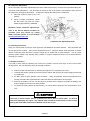
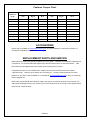
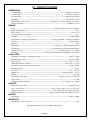
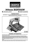
TABLE OF CONTENTS SUBJECT PAGE I - General Information and Safety Table of Contents--------------------------------------------------------------- 1 Warranty Information------------------------------------------------------------- 2 Emissions Control System Warranty ------------------------------------------------- 2 Vehicle Records ---------------------------------------------------------------- 3 Foreword --------------------------------------------------------------------- 4 4 – 11 Important Safety Information-------------------------------------------------Warnings and Cautions ------------------------------------------------------ 4–7 8 – 11 Some Words About Safety --------------------------------------------------Safety Labels ----------------------------------------------------------- 8–9 Qualifications for Users ------------------------------------------------- 10 – 11 Controls and Features ---------------------------------------------------- 12 – 17 II – Vehicle Controls and Operation Vehicle Features and Locations --------------------------------------------------- 18 Are You Ready To Drive? ------------------------------------------------- 19 – 20 Is Your Vehicle Ready to Drive? ------------------------------------------- 20 – 23 Starting Instructions ------------------------------------------------------- 23 – 24 Safe Driving Precautions -------------------------------------------------- 24 – 26 III - Unit Service Tire/Wheel Replacement ------------------------------------------------------ 26 Front End Alignment --------------------------------------------------------- 27 Front and Rear Shock Adjustment ------------------------------------------------- 27 Fuse Replacement ------------------------------------------------------------ 27 General Lubrication ----------------------------------------------------------- 28 Engine Lubrication ------------------------------------------------------------ 28 Air Filter ------------------------------------------------------------------ 29 Intake Cleaning - Engine Cooling Fan -------------------------------------------- 29 Spark Plug ---------------------------------------------------------------- 29 Chain Lubrication and Adjustment ----------------------------------------------- 30 Shifter Adjustment ---------------------------------------------------------- 30 Carburetor ---------------------------------------------------------------- 31 General Cleaning ------------------------------------------------------------ 31 Storage Instruction ----------------------------------------------------------- 31 Fastener Torque Chart -------------------------------------------------------- 32 Accessories ----------------------------------------------------------------- 32 Replacement Parts and Service -------------------------------------------------- 32 Dimensions ------------------------------------------------------------------ 33 Engine ---------------------------------------------------------------------- 33 Capacities ------------------------------------------------------------------ 33 Periodic Check and Service Table ---------------------------------------------- 34 Electrical Schematic --------------------------------------------------------- 35 IV - Specifications PAGE 1 OWNER’S/OPERATOR’S MANUAL – 200 SERIES PART NUMBER 14833R3 EMISSION CONTROL SYSTEM WARRANTY STATEMENT The Emission Control System Warranty on your American Sportworks vehicle is covered by Geason Enterprises, LLC dba Geason Powersports YOUR WARRANTY RIGHTS AND OBLIGATIONS The U.S. Environmental Protection Agency and Geason Enterprises, LLC dba Geason Powersports (hereinafter “Geason Powersports”) are pleased to explain the emission control system warranty on your 2012 and later Off-Road ATV. New off-road motor vehicles must be designed, built and equipped to meet U.S. EPA Federal anti-smog standards. Geason Powersports must warrant the emission control system on your vehicle for 5000km, or at least 30 months, whichever comes first, provided that there has been no abuse, neglect or improper maintenance of your vehicle. This ATV was designed to meet the emission standards for 10,000km, or 5 years, whichever comes first. Your emission control system may include parts such as the carburetor or fuel injection system, the ignition system, catalytic converter and engine computer, if it is equipped. Also included may be hoses, belts, connectors and other emission-related assemblies. Where a warrantable condition exists, Geason Powersports will repair your vehicle at no cost to you, including diagnosis, parts and labor. If an emission-related part on your vehicle is defective, the parts will be repaired or replaced by Geason Powersports. DEFECTS WARRANTY. This is your emission control system NOTICE! Use of any Geason Powersports vehicle in any type of competitive event completely and absolutely voids this and all other warranties offered by Geason Powersports. OWNER’S WARRANTY RESPONSIBILITIES As the vehicle owner, you are responsible for the performance of the required maintenance listed in your owner’s manual. Geason Powersports recommends that you maintain a record of all receipts covering maintenance on your vehicle, but Geason Powersports cannot deny a warranty claim solely for the lack of receipts or for your failure to ensure the performance of all scheduled maintenance. You are responsible for presenting your vehicle to the Geason Powersports dealer as soon as a problem exists. reasonable amount of time, not to exceed 30 days. The warranty repairs should be completed in a As the owner, you should be aware that Geason Powersports may deny your warranty coverage if your vehicle, or a part, has failed due to abuse, neglect, improper maintenance or unapproved modifications. If you use your vehicle in any type of competitive event, this warranty is immediately and completely void. If you have any questions regarding your warranty rights and responsibilities, you should contact Geason Enterprises, LLC dba Geason Powersports, 1200 Lakeside Parkway #325, Flower Mound, TX 75028, Phone 214-513-1700 or the U.S. Environmental Protection Agency, 2000 Traverwood Drive, Ann Arbor, MI 48105. WARRANTY COVERAGE Geason Enterprises, LLC dba Geason Powersports (hereinafter “Geason Powersports”) warrants that each new 2012 and later Geason Powersports off-road vehicle: A. is designed, built, and equipped so as to conform at the time of initial retail purchase with all applicable regulations of the United States Environmental Protection Agency, and; B. is free from defects in material and workmanship which cause such vehicle to fail to confirm with applicable regulations of the United States Environmental Protection Agency for the periods specified above. I. II. III. IV. V. VI. Coverage: Warranty defects shall be remedied during customary business hours at any authorized Geason Powersports dealer located within the United States of America in compliance with the Clean Air Act and applicable regulations of the United States Environmental Protection Agency. Any part of parts replaced under this warranty shall become the property of Geason Powersports. Limitations: This Emission Control System Warranty shall not cover any of the following: a. Repair or replacement as a result of i. accident ii. misuse iii. repairs improperly performed or replacements improperly installed, iv. use of replacement parts or accessories not conforming to specifications set forth by Geason Powersports, which adversely affect performance and/or v. use in competitive racing or related events b. Inspections, replacement of parts and other services and adjustments required for required maintenance c. Any vehicle equipped with an odometer or hour meter on which the odometer mileage or hour meter reading has been changed so that actual mileage cannot be readily determined. Limited Liability a. The liability of Geason Powersports under this Emission Control System Warranty is limited solely to the remedying of defects in material or workmanship by an authorized Geason Powersports dealer at its place of business during customary business hours. This warranty does not cover inconvenience or loss of use of the vehicle or transportation of the vehicle to or from the Geason Powersports dealer. Geason Powersports shall not be liable for any other expenses, loss or damage, whether direct, incidental, consequential, or exemplary arising in connection with the sale or use of or inability to use the Geason Powersports vehicle for any purpose. Some states do not allow the exclusion or limitation of any incidental or consequential damages, so the above limitations may not apply to you. b. No express emission control system warranty is given by Geason Powersports, except as specifically set forth herein. Any emission control system warranty implied by law, including any warranty of merchantability or fitness for a particular purpose, is limited to the express emission control system warranty terms stated in the warranty. The foregoing statements of warranty are exclusive and in lieu of all other remedies. Some states do not allow limitations on how long an implied warranty lasts, so the above limitations may not apply to you. c. No dealer is authorized to modify this Limited Emission Control System Warranty issues by Geason Powersports. Legal Rights: This warranty gives you specific legal rights, and you may also have other rights which vary from state to state. This warranty is in addition to the Geason Powersports limited vehicle warranty. Additional Information: Any replacement part that is equivalent in performance and durability may be used in the performance of any maintenance or repairs. However, Geason Powersports are not liable for these parts. The owner is responsible for the performance of all required maintenance. Such maintenance may be performed at a service establishment or by an individual. The warranty period begins on the date the ATV is delivered to an ultimate purchaser. PAGE 2 OWNER’S/OPERATOR’S MANUAL – 200 SERIES PART NUMBER 14833R3 MY VEHICLE IDENTIFICATION NUMBER Record the Vehicle Identification Number (VIN) and Model number of your American SportWorks vehicle below for service and insurance records. The VIN is hard tagged on the vehicle frame under the bed. VIN: L6KUA00__ __ __ __ __ __ __ __ __ __ Model: __ __200 AMERICAN SPORTWORKS LIMITED WARRANTY American SportWorks (hereinafter referred to as “ASW”), hereby warrants to the original purchaser, that the frame components of new ASW vehicles will be free from defects in material and workmanship. The period of warranty is (1) year from date of purchase for the component parts (except as noted below), and (1) year from the date of purchase for the frame and (1) year from the date of purchase for the engine. ASW, if notified of a defect in material or workmanship during the period of warranty, will repair or replace, at its option, defective parts at no charge, other than the reasonable cost for the transportation of the component(s). ASW will also agree to pay reasonable charges for labor, if necessary, to perform a warranty repair. Proof of Purchase must be provided to an approved ASW service center before any warranty work is performed. The original purchaser must operate the vehicle and maintain the vehicle in accordance with the instructions provided in the Operator’s Manual, the supplements hereto, and labels affixed to the vehicle. Additionally, within (10) days of the discovery of an alleged defect, the original purchaser must contact ASW’s Customer Service Department at 1-800-643-7332, 4404 Engle Ridge Drive, Fort Wayne, IN 46804 or via the internet at www.amsportworks.com. The repair or replacement of any part or parts under this Limited Warranty shall not extend the term of the warranty beyond the original term as set forth above. General Exclusions: This limited warranty does not cover component failure or damage caused by any of the following: abnormal strain or stress, neglect; abuse; improper assembly of components which were supplied in the factory sealed carton after the vehicle left ASW; improper maintenance, improper use of the vehicle, including, but not limited to racing, jumping, stunt driving, overloading, or any other uses prohibited by the Operator’s Manual. Additionally, this warranty does not cover component failure or damage to vehicles which are leased, rented, or used at a concession track. Specific Exclusions: This limited warranty does not apply to components, which are subject to normal wear and tear and natural discoloration of material due to ultraviolet light. These items include, but are not limited to, the tires, brakes, throttle, shift and brake cables, drive belt, the torque converter system, chain, seat, lights, fasteners, decals, or cosmetic body panels. Downtime, pick-up and delivery charges are not covered by this warranty. ASW MAKES NO OTHER WARRANTY OF ANY KIND, EXPRESSED OR IMPLIED. ALL WARRANTIES OF MERCHANTABILITY AND FITNESS FOR A PARTICULAR PURPOSE WHICH EXCEED THE OBLIGATIONS AND TIME LIMITATIONS SPECIFIED IN THE WARRANTY ABOVE ARE HEREBY DISCLAIMED BY ASW AND EXCLUDED FROM THIS WARRANTY. ADDITIONALLY, THIS WARRANTY EXCLUDES ANY INCIDENTAL OR CONSEQUENTIAL DAMAGES, INCLUDING BUT NOT LIMITED TO LOSS OF USE. SOME STATES DO NOT ALLOW A MANUFACTURER TO EXCLUDE OR LIMIT INCIDENTAL OR CONSEQUENTIAL DAMAGES AND, THEREFORE, THE ABOVE EXCLUSION MAY NOT APPLY TO YOU. SOME STATES DO NOT ALLOW LIMITATIONS ON HOW LONG AN IMPLIED WARRANTY WILL LAST; IT IS POSSIBLE THAT THE ABOVE LIMITATION MAY NOT APPLY TO YOU. THIS WARRANTY GIVES YOU SPECIFIC LEGAL RIGHTS, AND YOU MAY ALSO HAVE OTHER LEGAL RIGHTS, WHICH VARY, FROM STATE TO STATE. PAGE 3 OWNER’S/OPERATOR’S MANUAL – 200 SERIES PART NUMBER 14833R3 FOREWORD Congratulations on the purchase of your ASW Vehicle. Before operating this vehicle, the owner and each operator must understand that, unless specifically equipped and labeled as a street legal Low Speed Vehicle (LSV), this vehicle was not designed or manufactured to meet specifications for use on public roads, streets, highways and thoroughfares The owner, operator(s) and passenger(s) must read and understand all the instructions for proper assembly and safe operation, as well as the instructions concerning the engine and all other portions of the vehicle as described and illustrated in this manual and on the included safety video. This unit is not designed for children, and is not a toy. Be sure to follow the recommended maintenance schedule and service your vehicle accordingly. Preventative maintenance is extremely important to the longevity of your vehicle. NOTE: A new vehicle requires an engine break in period of 5 hours, whereby the engine oil MUST be changed (See SERVICE section) First time drivers are urged to seek instruction from a dealer or qualified instructor before and during the initial use of this unit. It is also recommended to practice in a large open area to become familiar with the operation of the vehicle. We hope you will have a fun, safe experience with our products and thank you again for choosing an American Sportworks Vehicle. * IMPORTANT SAFETY INFORMATION * WARNINGS AND CAUTIONS This is the safety alert symbol. When you see this symbol on your machine or in this manual, be alert to the potential for personal injury. Read and follow all instructions in this Owner’s/Operator’s manual and any accompanying supplements before attempting to operate this vehicle. Make sure to view the Operations and Safety video. WARNING Indicates a potential hazard that could result in severe personal injury or death. CAUTION Indicates a potential hazard which may result in personal injury or damage to the machine. NOTE: Use of the word “NOTE” will alert you to key information or instructions. PAGE 4 OWNER’S/OPERATOR’S MANUAL – 200 SERIES PART NUMBER 14833R3 WARNING 1. Exhaust fumes are toxic. a. California Proposition 65 WARNING: Gasoline engine exhaust from this machine contains chemicals known to the State of California to cause cancer, birth defects, or other reproductive harm. The engine exhaust contains carbon monoxide, which is a tasteless, odorless, poisonous gas. b. NEVER operate this vehicle indoors or in an enclosed area without adequate ventilation 2. NEVER adjust, repair, or clean the machine while it is in motion. 3. Check tire pressure before each use. a. Prior to operating the vehicle check and adjust tire pressure to the proper operating pressure as indicated on the sidewall of each tire or in the specification section of this manual. A tire pressure gauge is required to obtain accurate readings. 4. Safety decals must be replaced if they become unreadable or detached from the vehicle. a. If decals are unreadable or missing, warning of potential hazards or safety requirements may be lacking. 5. The safe operation of this vehicle is dependent upon the operator’s ability to exercise proper judgment. a. Operator and passenger must not be too small or too large for controlled operation. b. Operator and passenger must be of sufficient age, understanding, mental capacity, and physical capacity to safely operate the vehicle. c. Vehicle should only be operated after mature, supervised instruction and sufficient practice in an un-congested area. 6. This vehicle may have been supplied to you completely assembled. To prevent injury or death read and follow the assembly instructions to make sure the unit was assembled properly. 7. It is strongly recommended that Operator and any passengers wear a properly fitting motorcycle helmet approved by agencies such as the Department of Transportation (DOT), Safety Helmet Council of America (SHCA), or Snell Memorial Foundation (SNELL). a. Most accident fatalities are due to head injuries. b. Operator (and any passenger) should also wear face shields or goggles, boots, gloves and other appropriate protective clothing. (See MACHINE OPERATION) 8. Vehicle modification or removal of original equipment or safety decals can render the machine unsafe for operation. 9. Long hair, loose clothes, or jewelry can get caught in moving parts below and behind the seat or surrounding environment. a. Remove or tie back anything loose that can reach below and behind the seat before riding. 10. Keep guards in place at all times. a. Prevent accidental contact by the operator or service personnel while the vehicle is running. b. The guards over the brake, clutch or torque converter, axle and drive sprockets also help prevent mud and debris from coming in contact with those items. 11. Be sure the passenger restraint system (i.e. Seat Belt) is properly adjusted and fastened at all times during operation. a. If the passenger restraint system is not properly used by the operator and/or passengers, loss of control and possible personal injury and/or vehicle damage can occur. PAGE 5 OWNER’S/OPERATOR’S MANUAL – 200 SERIES PART NUMBER 14833R3 WARNING 12. When there is no passenger in the vehicle, the passenger seatbelt must be securely fastened within the vehicle. a. If the passenger restraint system is not properly used by the operator and/or passenger, loss of control and possible personal injury and/or vehicle damage can occur. 13. NEVER start the engine without checking to see that the throttle control is in idle position. 14. NEVER tamper with, alter, or change the vehicle engine governor settings. a. The governor, as set by the engine manufacturer, limits maximum engine speed and protects the engine from damage. b. Excessive engine speed is potentially dangerous to operator, passengers, bystanders, and engine. 15. All screws, nuts, and bolts must be properly tightened to make sure the vehicle is in safe operating condition. 16. NEVER place hands, feet, or any body parts or clothing near the engine, wheels, chain, and other rotating parts of the vehicle while riding or running the engine. a. Use caution in performing required maintenance on or near operating engine. b. Use caution after the engine has been running, since the engine and other drive components may be extremely hot. 17. Check fuel supply before each use. a. NEVER fill fuel tank while the engine is running or hot. b. DO NOT overfill tank. c. ALWAYS allow at least ½” of expansion space at the top of tank. d. There should not be any fuel in the filler neck. e. Replace cap tightly to prevent a fuel spillage fire hazard. NOTE: Always use an original gas cap or OEM replacement. - NEVER fill fuel tank while the vehicle is inside a building. - After filling the tank, move the vehicle at least ten feet before attempting to start the engine. 18. ALWAYS use extreme caution when starting the engine. a. Hot engine, muffler, or drive components can burn on contact. 19. ALWAYS SLOW DOWN when turning. a. High-speed turning can cause loss of control and/or possible operator injury. b. Turning on a slope increases the risk of rollover. c. Practice operation is required to coordinate turning skill. d. Failure to operate this vehicle at a safe speed while turning can result in a strong possibility of severe personal injury. 20. Washing or operating the vehicle in freezing temperatures can result in water freezing in the throttle cable conduit and/or on the throttle mechanism. a. This may result in the throttle sticking which can cause the engine to continue to run and result in loss of control. 21. When making repairs or adjustments to the vehicle, the spark plug wire MUST be disconnected and kept away from the spark plug to prevent accidental starting. a. When working on, around, or restarting engine, use extreme caution to avoid contact with the muffler, cylinder head or any potentially hot area on or around the engine. b. Ensure that all guards are in place prior to starting the engine. PAGE 6 OWNER’S/OPERATOR’S MANUAL – 200 SERIES PART NUMBER 14833R3 WARNING 22. Operating the vehicle in conditions where water, mud, snow, dirt, sand, or other debris can get into the throttle cable conduit and/or on the throttle mechanism can cause binding of the cable and/or the throttle mechanism. a. This may result in the throttle sticking which can cause the engine to continue to run and result in loss of control. 23. Assembly, maintenance, and/or repair of this vehicle should only be performed by designated dealers or authorized small engine centers (for engine repairs) so that no unsafe conditions or modifications are made. 24. Wet, slippery, rough, or sloped terrain is potentially dangerous and may result in injury if proper caution is not observed. a. ALWAYS SLOW DOWN b. Operator must use mature judgment, skill, and experience to choose a speed suitable for terrain and riding conditions in protecting operator and any bystanders. c. Operator must use mature judgment, skill and experience in choosing suitable terrain for individual operational capabilities. 25. Prevailing-torque type locknuts must be replaced with new after the old locknuts have been removed. a. Replace with the same type of locknut to make sure they function properly. Refer to the maintenance section for more information on locknuts. 26. NEVER operate the vehicle while under the influence of alcohol, drugs, or medication of any kind. a. Such operation is dangerous to yourself and/or others. 27. Read and keep all supplied printed material. a. Supplements to this Operator’s Manual contain updated information relative to your specific vehicle model. It is important to keep all of these documents for reference. CAUTION 1. During vehicle storage, keep it in a place where gasoline fumes will not reach an open flame, spark, or other source of ignition. For long term storage: a. Disconnect the battery b. Drain fuel tank and carburetor bowl in a well-ventilated, open, cool area. c. Engine must be allowed to cool before storage in any enclosure. d. NEVER store the vehicle in close proximity to appliances such as hot water heaters or furnaces. 2. Brush Bars assembled to this vehicle are for decorative purpose and limited brush protection. a. Brush Bars were not designed for roll over or to restrict all brush or tree branches from protruding into operator/passenger compartment. 3. If the vehicle should start making unusual noise or vibrating abnormally, the engine should be stopped and the spark plug wire disconnected. The vehicle should then be checked for damage. Excessive noise or vibration is generally a warning of loose or worn parts. PAGE 7 OWNER’S/OPERATOR’S MANUAL – 200 SERIES PART NUMBER 14833R3 SOME WORDS ABOUT SAFETY The following pages present important information and recommendations to help you drive your vehicle safely. Please read through these pages thoroughly and view the Safety DVD that was included with your unit. SAFETY LABELS The following labels have been applied to your unit and should be considered as permanent parts of the vehicle. If a label should come off, become hard to read, or become damaged, contact your dealer or American SportWorks Customer Service department for warning label replacements. PAGE 8 OWNER’S/OPERATOR’S MANUAL – 200 SERIES PART NUMBER 14833R3 PAGE 9 OWNER’S/OPERATOR’S MANUAL – 200 SERIES PART NUMBER 14833R3 QUALIFICATIONS FOR USERS This vehicle is recommended for use by operator and passenger with a minimum age of sixteen years. Vehicles are intended for use by operators who meet the physical and cognitive capabilities set out by the manufacturer in the material provided with the vehicle. Consumer Responsibility for Safe Use and Maintenance of a Vehicle 1. Vehicle shall not be modified from the manufacturer’s original design and configuration. 2. Vehicle shall not be used to perform racing, stunt riding, jumps, spinouts, donuts, or other maneuvers as they may cause loss of control. As such, these activities are likely to result in possible injury to the operator, bystanders, or both. 3. Prior to each use, the operator shall perform the preoperational checks specified by the manufacturer, and further verify: a. Smooth throttle operation and positive return of the throttle linkage to a closed throttle position when released; b. That the throttle cable and linkages operate properly and the throttle cable or other linkages be adjusted properly; c. That the steering linkage is adjusted and operates smoothly; d. That the engine stop switch is properly functioning; e. That all guards originally supplied by the manufacturer are in proper place in serviceable condition; f. That engine idle speed is below the point of clutch or torque converter engagement; g. That the gas tank is in good condition and the proper gas cap is fastened securely; h. That the braking system is functioning properly; i. That all safety labels are in place, legible and understood; j. That any and all axle guards, chain guards, torque converter covers, or other covers or guards supplied by the manufacturer are in place and in serviceable condition; k. That tires are in good condition, inflated properly, and have sufficient tread remaining; and l. That all fasteners are in place and tightened securely. 4. Vehicle engines shall not be started unless the operator is seated in proper position for vehicle operations and the brake fully engaged. 5. Long hair, loose clothes, or jewelry can get caught in moving parts below the seat or surrounding environment. Remove or tie back anything loose that can reach below or behind the seat before riding. 6. Vehicles shall only be fueled by an operator knowledgeable with regard to proper fueling techniques. 7. All operators or riders shall be knowledgeable, capable, and have the cognitive capacity to operate the vehicle safely, including those items specified in 1 through 6. 8. Vehicle operators and passengers shall adhere to all manufacturer’s recommendations and instructions, as well as comply with all laws and ordinances, as well as: a. Operators shall stay seated with both hands on the steering wheel and both feet in the vehicle at all times, whether moving or stationary, unless the vehicle is stopped completely and the engine has been shut off. b. Passengers shall remain seated with arms and legs inside the vehicle at all times during vehicle operation. PAGE 10 OWNER’S/OPERATOR’S MANUAL – 200 SERIES PART NUMBER 14833R3 c. Shall observe minimum age restrictions. d. Shall not ride the Vehicle if long hair, loose clothes, or jewelry reach below or behind the seat. WARNING Long hair, loose clothes, or jewelry can get caught in moving parts below and behind the seat or surrounding environment. Remove or tie back anything loose that can reach below or behind the seat before riding. e. Shall not allow smoking in vehicle. f. Persons under the influence of drugs, alcohol, or intoxicants shall not supervise, operate, or ride in a vehicle. Vehicles shall operate only on a surface or terrain recommended by the vehicle’s manufacturer. g. Vehicles shall not be operated on roads, streets, highways, or any other location where road vehicles are intended to travel unless specifically designed and designated for such use. h. Vehicles shall be operated only with adequate lighting and under conditions of suitable visibility. 9. Persons with the following conditions shall not ride in or operate a Vehicle: a. Those with heart conditions b. Pregnant women c. Persons with head, back, or neck ailments, or prior surgeries to those areas of the body. d. Persons with any mental or physical conditions, which may make them susceptible to injury or impair their physical dexterity or mental capabilities to recognize, understand, and perform all of the safety instructions, and be able to assume the hazards inherent in vehicle use. 10. Vehicle shall not be used to: a. Transport a passenger, or passengers, except in the seating area(s) provided. b. Transport materials or equipment in excess of the rated cargo capacity; 11. Vehicle operators always shall use appropriate protective clothing, including but not limited to a motorcycle type helmet and eye protection, with appropriate certification, and any other equipment recommended by the vehicle manufacturer including gloves, footwear, long sleeve shirts, and long pants. 12. No operator or other person shall contact any portion of the engine, wheels, or drive train for any purpose including maintenance until the engine has been turned off and allowed to cool, and the vehicle is in a stable and stationary position. 13. Passenger restraints must be used in accordance with, and limited to, the manufacturer’s guidelines. 14. Vehicle components shall be maintained and repaired in accordance with the manufacturer’s specifications and utilizing only the manufacturer’s authorized replacement parts with installation performed by designated dealers or other skilled persons. PAGE 11 OWNER’S/OPERATOR’S MANUAL – 200 SERIES PART NUMBER 14833R3 II - VEHICLE CONTROLS AND OPERATION Controls and Features WARNING Do not attempt to start or operate the engine until completely familiar with the location and use of each control necessary to operate this vehicle. The operator must know how to stop this machine before starting and driving it. SWITCH – CARGO LIGHT CUP HOLDER KEYED IGNITION STEERING WHEEL 12V POWER OUTLET SWITCH – HEAD LIGHT MANUAL CHOKE (IF SO EQUIPPED) PARK BRAKE LEVER BRAKE PEDAL THROTTLE PEDAL A. Throttle The foot pedal on the right is the throttle (See Figure), to control the speed of the vehicle. As the engine speed increases above idle, the clutch automatically engages and moves the vehicle forward. To disengage the clutch at any time, allow the throttle to return to the idle position. WARNING Every time, prior to starting the engine, check the throttle assembly to ensure that when the pedal is pushed all the way forward the assembly is working smoothly and returns to idle when released. idle position. Do not operate this unit if pedal or engine throttle linkage fail to return to the If unable to correct the problem through lubrication, adjustment or replacement of worn parts, contact your dealer for assistance. PAGE 12 OWNER’S/OPERATOR’S MANUAL – 200 SERIES PART NUMBER 14833R3 B. Brake The brake is controlled by the foot pedal on the left (See Figure). Applying pressure to the pedal draws the brake pads against the brake discs at the wheels and slows or stops the vehicle. C. Parking Brake This vehicle is equipped with a parking brake system. The parking brake lever can be found in front of the passenger seat just under the dash. To apply the brake, simply depress the brake pedal and pull back on the parking brake lever, locking it into position. To disengage, depress the pedal, push the thumb button located at the top of the lever and return to its original position towards the front of the vehicle. C. Lights This vehicle is equipped with front running lights, a rear running/brake lamp, and a rear facing cargo light. To turn the running lights on, flip the lower switch located next to the keyed ignition on the dashboard of the unit. The cargo light can be turned on by flipping the upper switch located next to the keyed ignition. (See Figure) The rear brake light will activate automatically when the brake pedal is depressed. D. Power Outlet This vehicle also is equipped with a 12V, 15amp power outlet for plugging in accessory items, and comes standard with a rubber cap. E. Do not exceed the maximum amperage rating of the plug. Keyed Ignition Switch For added security, this unit is equipped with a keyed ignition switch. will only start the engine when brake pedal is depressed. are turned off when the key switch is in the “OFF” position. The keyed ignition As an added feature, all lights Refer to page 25 for specific starting instructions. F. Manual Choke Some units come equipped with a manual choke in lieu of an automatic electric choke. The choke is used to assist in cold engine starting. The choke is “ON” when the knob is pulled out completely and “OFF” when the knob is pushed in completely. Refer to page 25 for specific starting instructions. G. Rear View Mirror The unit is equipped with a rear view mirror. Adjust the mirror such that objects can be easily seen while sitting in correct driving position. H. Seat Adjustment The unit is equipped with an adjustable seat. move the seat either forward or backward. To adjust, lift the levers just in front of the seat bottom and Release the levers at the desired seat location, ensuring that they both snap back into place to lock the seat. WARNING Never operate this vehicle when the seat is not securely locked into position. or death could occur due to loss of control. Serious injury Always make seat adjustments with the vehicle fully stopped and the engine shut off. PAGE 13 OWNER’S/OPERATOR’S MANUAL – 200 SERIES PART NUMBER 14833R3 I. Occupant Restraints This vehicle is equipped with automotive style 3 point retracting seat belts. tongue into the buckle until it is securely attached. Insert the metal Final adjustments should be made with the plastic tension stop such that the belt is against the shoulder and chest with no excess slack. This vehicle is also equipped with a passenger grab bar located on the dash directly in front of the passenger seat. J. Under-seat Storage This vehicle is equipped with a storage area under the seat. To access the storage area, seat belts must be unlatched and the seat must be cleared of riders or objects. Provision for a padlock or combination lock (not included) is available on the seat latch handle. To open the storage area, remove any lock and press the lever down. With the lever depressed, lift the rear of the seat and rotate forward to reveal the storage space. NOTE: The under-seat storage area is not watertight. Items that need to stay dry should be bagged or placed in a watertight container within the storage area. LATCH HANDLE UNDER-SEAT STORAGE SEAT ADJUSTMENT LATCH WARNING Failure to fully latch the seat in the closed position could result in seat movement while driving and cause serious injury or death. Always ensure that the seat is fully latched before driving. K. Gear Selection This vehicle is equipped with a Forward / Neutral / Reverse transmission. To shift gears, always bring the vehicle to a complete stop and let the engine RPM stabilize to the idle level. With the brake applied, move the shift lever to the desired gear and gently depress the throttle pedal. CAUTION Damage to the vehicle will occur if the unit is shifted into a different gear while the vehicle is still in motion. ALWAYS bring the vehicle to a complete stop before selecting a different gear. PAGE 14 OWNER’S/OPERATOR’S MANUAL – 200 SERIES PART NUMBER 14833R3 L. Tool Holders This vehicle is equipped with standard side mounted tool holders for safely carrying garden tools such as rakes, shovels, etc… The tool holders are rubber coated and spring loaded to keep the tool from bouncing or rattling while the unit is in motion. Shorter tools may be loaded into the tool holders provided the handle is long enough to protrude through the middle loop, and provided the head of the tool bottoms out against the rotating loop. designed to rotate in the COUNTERCLOCKWISE direction only. The holders are To insert tool: 1) Rotate the tool horizontally and slide the handle through the loop from the RIGHT side 2) Rotate the tool vertically in a COUNTERCLOCKWISE direction 3) Slide the tool downward through the second loop and onto lower tool rest Step 1 Step 2 Step 3 WARNING Ensure that all tools are correctly and securely loaded into the tool holders before driving. Failure to secure the tool could cause damage to the unit, and cause serious injury or death. CAUTION Long tools will extend past the overhead brush bars, increasing the overall height of the vehicle. Damage to the tool, unit or to surrounding structures will occur when driving into low overhead clearances. M. Cargo Dump Bed – 250lb MAX LOAD This vehicle is equipped with a manual rear dump cargo bed. Release levers are located on both the driver and passenger sides of the vehicle just forward and above the rear wheels. Loose cargo should be secured with a cargo net, or proper cargo straps to prevent shifting during transport. This bed is NOT designed to transport people or animals and should be used for hauling cargo only. Prior to dumping any loads, the parking brake should be applied and the keyed ignition turned to the “OFF” position. To dump the bed, unlatch and lower the tailgate. the side of the unit, pull the release lever upwards then manually tilt the bed to dump the load. Standing to After dumping, the bed and tailgate should be securely latched. PAGE 15 OWNER’S/OPERATOR’S MANUAL – 200 SERIES PART NUMBER 14833R3 WARNING Do not lean over the bed while releasing the bed latch. Loads shifted towards the tailgate may cause the front of the bed to suddenly raise when unlatched causing serious injury. CAUTION Ensure that the bed is securely latched before driving the unit. Failure to properly latch bed may result in damage to cargo, or to the unit. N. TAILGATE LATCH AND REMOVAL Latch Lock The tailgate on this unit has been fitted with cam over style latches. The latches are designed to secure the tailgate to the bed, while minimizing rattles. To unlatch the tailgate, depress the latch lock and pull the hasp away from the tailgate. Once unlatched, the tailgate will swing freely towards the rear bumper. To latch, simply close the gate securely against the bed tube and lock the wire hasp over the bed latch. Bed Latch Removal of the tailgate requires a 10 and 12mm wrench and removal of the hinge bolts. If the tailgate is removed, temporarily install the hinge bolts into the tailgate to prevent loss of the fasteners. O. DRAWBAR HITCH - 500lb MAX LOAD (Rolling) This vehicle may be equipped with a drawbar style hitch for towing light utility karts, non-ground engaging lawn equipment, and various attachments. Pull behind mower decks are not approved for use with this vehicle because the partial throttle / slow travel speed required causes continuous CVT clutch slippage and pre-mature drive train wear. This drawbar is NOT designed to accept equipment with hitch ball type tongues. Drawbar hitch is designed for 75lb maximum tongue weight. CAUTION Ensure that towed items fall within the listed load ratings AND are approved devices. Exceeding the rated load, or using unapproved devices, will cause damage to both the drawbar hitch and engine drive-train that is not covered by warranty. PAGE 16 OWNER’S/OPERATOR’S MANUAL – 200 SERIES PART NUMBER 14833R3 F. Manual Fuel Valve Some units come equipped with a manual fuel valve in lieu of an engine vacuum operated valve. The manual valve provides the added feature of a “reserve” position which provides access to a reserve fuel supply allowing additional driving range to get to a fuel filling station should the main fuel supply be used completely. OFF: With the fuel valve in the OFF position, fuel cannot flow from the tank to the carburetor. Turn the fuel valve OFF whenever the unit is not in use or during transport. Note: If the unit is being transported from one location to another, i.e. in the bed of a pick-up truck or on a trailer, turn the fuel valve OFF to prevent excess fuel flow into the carburetor. This can cause engine “flooding” and difficulty starting. ON: With the fuel valve in the ON position, fuel will flow from the main fuel supply to the carburetor. RESERVE: With the fuel valve in the RESERVE position, fuel will flow from the reserve fuel supply to the carburetor. fuel supply is gone. Use this only when the main Proceed directly to refill the tank with fuel once switching to the RESERVE position. Note: Return the fuel valve to the ON position after refueling. If the valve is left in the RESERVE position you may run out of fuel and have no reserve. PAGE 17 OWNER’S/OPERATOR’S MANUAL – 200 SERIES PART NUMBER 14833R3 VEHICLE FEATURES AND LOCATIONS OVERHEAD BRUSH BARS 3PT SAFETY BELTS REAR VIEW MIRROR PASSENGER GRAB BAR TOOL HOLDER STEERING WHEEL FUEL TANK MANUAL DUMP CARGO BED CUP HOLDER BED LATCH FUEL VALVE HIP GUARD ADJUSTABLE SEAT RUNNING LIGHTS BUMPER UNDER-SEAT STORAGE THROTTLE PEDAL PARKING BRAKE BRAKE PEDAL SHIFT LEVER PAGE 18 OWNER’S/OPERATOR’S MANUAL – 200 SERIES PART NUMBER 14833R3 ARE YOU READY TO DRIVE? Before each drive, you need to make sure that you and your vehicle are both ready to drive. To help get you prepared, this section discusses how to evaluate your driving readiness, what items you should check on your vehicle, and adjustments to make for your comfort, convenience, or safety. Before you drive your vehicle for the first time, we urge you to: - Read this owner’s manual and the labels on your vehicle carefully. - Make sure you understand all the safety messages. - Know how to operate all the controls. - View and understand the included safety DVD Protective Apparel Although complete protection is not possible, wearing proper gear can reduce the chance of injury should you have an accident. The following suggestions will help you choose the proper protective gear. Helmet and Eye Protection Your helmet is your most important piece of protective gear because it offers the best protection against head injuries. A helmet should fit your head comfortably and securely. Open-face helmets offer some protection, but a full-face helmet offers more. Regardless of the style, look for a D.O.T. (Department of Transportation) or Snell Memorial Foundation (SNELL) sticker on any helmet you buy. Always wear a face shield or goggles to protect your eyes and help your vision. WARNING Operating this vehicle without wearing an approved motorcycle helmet, eye protection, and protective clothing could increase your chances of head and/or eye injury, and the possibility of death in the event of a severe accident. Always wear an approved motorcycle helmet that fits properly and wear eye protection (goggles or face shield), gloves, boots, long-sleeved shirt or jacket and long pants. Additional Driving Gear In addition to a helmet and eye protection, we also recommend: - Sturdy boots to help protect feet, ankles, and lower legs. - Gloves to help protect your hands Driver Training Developing your driving skills is an ongoing process. Even if you are and experienced driver, take time PAGE 19 OWNER’S/OPERATOR’S MANUAL – 200 SERIES PART NUMBER 14833R3 to become familiar with the controls and how the vehicle handles. to develop your skills. Practice driving in a safe, open area Do not drive on rough terrain until you get accustomed to the vehicle controls and feel comfortable with its size and weight. WARNING Operating this vehicle without your seat belt could cause you to be thrown from the unit, causing serious injury or death. No Alcohol or Drugs Alcohol, drugs and vehicles don't mix. a vehicle safely. vehicle. Even a small amount of alcohol can impair your ability to operate Likewise, drugs, even if prescribed by a physician, can be dangerous while operating a Consult your doctor to be sure it is safe to operate a vehicle after taking medication. WARNING Operating this vehicle after consuming alcohol or drugs can seriously affect your judgment, cause you to react more slowly, affect your balance and perception, and could result in serious injury or death. Never consume alcohol or drugs before or while operating this vehicle. IS YOUR VEHICLE READY TO DRIVE? Before each drive, it is important to inspect your vehicle and make sure any problems you find are corrected. A pre-drive inspection is a must, not only for safety, but because having a breakdown, or even a flat tire, can be a major inconvenience. If your vehicle has overturned or has been involved in a collision, do not drive it until your vehicle has been inspected by your dealer. There may be damage or other problems that you cannot see. WARNING Improperly maintaining this vehicle or failing to correct a problem before driving can cause an accident resulting in serious injury or death. Always perform a pre-drive inspection before every drive and correct any problems. PAGE 20 OWNER’S/OPERATOR’S MANUAL – 200 SERIES PART NUMBER 14833R3 Fueling Your Vehicle The fuel tank is located directly behind the passenger seat on this vehicle and can be filled from either the front or back of the fuel tank. To aid in filling, it may be necessary to either unlatch and lift the dump bed, or unlatch and tilt the seat forward. With the vehicle in a well-ventilated area, and following the warnings listed below, unscrew the fuel cap and fill the tank with a mid-grade unleaded gasoline (89-93 Octane). Replace the cap securely and secure the seat and/or dump bed as needed. Note: If the manual fuel valve is being used in the “RESERVE” position, return the fuel valve to the “ON” position after refueling. If the valve is left in the “RESERVE” position you may run out of fuel and have no reserve. WARNING Check fuel supply before each use. - NEVER fill fuel tank while the engine is running or hot. - DO NOT overfill tank. - ALWAYS allow at least ½” of expansion space at the top of tank. - There should not be any fuel in the filler neck. - Replace cap tightly to prevent a fuel spillage fire hazard. NOTE: Always use an original gas cap or OEM replacement. - NEVER fill fuel tank while the vehicle is inside a building. - After filling the tank, move the vehicle at least ten feet before attempting to start the engine. CAUTION This engine is not designed for Flex Fuel operation. Attempting to use anything other than the mid-grade 89-93 octane automotive fuels will cause damage to the engine. Pre-Ride Inspection The following checklist should be utilized to inspect your vehicle before each use to ensure that it is in proper working order. ENGINE STOPPED CHECKLIST Yes Y No ITEM INSPECTION PROCEDURE ACTION Engine Oil Level Oil Level – Check dipstick Add - Ref page 26 N Leaks - Check for leaks Check drain and filler plug Y Tighten Filler Cap/Dipstick for tightness Level - Add fuel if necessary Ref page 19-20 N DO NOT overfill DO NOT refuel a hot engine Y DO NOT mix oil with gas Fuel Y Replace cap and tighten Warning Decals Y N are legible and securely Y attached Tires Y Ensure that all warning decals N Replace as necessary Tread – 1/8” min depth Replace as necessary Pressure – 15 PSI with gauge Inflate as necessary Y PAGE 21 OWNER’S/OPERATOR’S MANUAL – 200 SERIES PART NUMBER 14833R3 Chain Tension – ½”-3/8” slack Ref page 28 Chain Lubrication Ref page 28 Smooth Operation – Ensure Replace damaged cable N pedal ‘snaps’ back to idle or lubricate w/spray lube Y Cable – check for loose or Replace damaged cable Drivetrain Y N Y Y Throttle frayed cable Fasteners Y Mud / Debris / Ice – Ensure Clean out mud / debris that mechanism is free and Move unit to warm location clear to de-ice Wheel Fasteners – Ensure all Tighten – Ref page 30 N wheel nuts are tight Y Missing / Loose Fasteners – Replace missing fasteners ensure all fasteners are present Tighten – Ref page 30 and securely tightened Brush Bars Y N Y Y N In place and attached Replace as necessary Tighten – Ref page 29 Operation – Ensure steering Steering Lubricate – Ref page 25 turns freely Y Toe – Ensure toe is adjusted Adjust – Ref page 25 properly Frame/Chassis Y N Y Y N Bent / Damaged – Check for Replace as necessary damaged components Connections – Ensure both Battery Tighten as necessary terminals securely fastened Y Corrosion – Ensure that no Clean as necessary corrosion is present Guards Y battery is secure in holder necessary Location - In place Replace as necessary Condition – Ensure that Y Guards are not damaged Operation – Ensure that lights, N including the brake light, are Y properly functioning Replace bulbs as necessary Operation – Ensure that ball Replace / Lubricate as N joints, shocks and bushings necessary with grease Y are moving freely Suspension Y Replace / Secure as N Lights Y Cover / Strap – Ensure that Fasteners – Ensure that all Tighten – Ref page 28 fasteners are in place and securely tightened Operation – Ensure that belt Seat Belts Y Y N extend and retract, ensure Y that latches are operational N Bed and Seat Operation – Ensure that seat Latches and Bed latches are secured Replace as necessary Latch or Adjust as necessary Y PAGE 22 OWNER’S/OPERATOR’S MANUAL – 200 SERIES PART NUMBER 14833R3 Tool Holders Y N Y Y Operation – Ensure that tools Remove or secure tool are fully secured Operation – Engage brake and Park Brake N Attempt to roll the unit forward Y Cable – Check for loose or Adjust as necessary Replace as necessary frayed cable Cooling Fan Y N Operation – Ensure that fan Clean - Ref page 27 is free of debris Y Starting Instructions Starting Instructions with Auto-Choke The following instructions list the proper method for starting your auto choke equipped vehicle. (No choke cable located on dash next to ignition key.) All models are equipped with a brake interlock switch, which requires the operator to depress the brake pedal while starting the engine. Note: Refer to the Assembly Instructions provided with this vehicle for the initial start-up procedure if this is the first time starting this unit. 1. Apply the park brake by depressing the brake pedal and engaging the lever located under the dash, just in front of the passenger seat. 2. Fasten seatbelt. 3. Pump the throttle pedal several times to ensure that the pedal operates and returns smoothly. 4. Insert the key into the ignition and turn to the “START” position allowing the engine to turn over. Caution: Do not let the engine turn over for more than 5 seconds at a time, as this may cause starter damage. 5. Once the engine is started, let off the key switch and let the engine idle for several minutes until the auto-choke feature releases and allows the engine idle to stabilize. 6. The key switch should always be turned to the “OFF” position when the vehicle is not in use to ensure all lights are off and to prevent draining of the battery. Starting Instructions for a Cold Engine with Manual Choke The following instructions list the proper method for starting your manual choke equipped vehicle. (A choke cable is located on dash next to ignition key.) All models are equipped with a brake interlock switch, which requires the operator to depress the brake pedal while starting the engine. Note: Refer to the Assembly Instructions provided with this vehicle for the initial start-up procedure if this is the first time starting this unit. 1. Turn the manual fuel valve to the “ON” position. 2. Apply the park brake by depressing the brake pedal and engaging the lever located under the dash, just in front of the passenger seat. 3. Fasten seatbelt. 4. Pump the throttle pedal several times to ensure that the pedal operates and returns smoothly. 5. Pull the choke lever all the way out (fully “ON”) 6. Insert the key into the ignition and turn to the “START” position allowing the engine to turn over. Caution: Do not let the engine turn over for more than 5 seconds at a time, as this may cause starter damage. 7. Once the engine starts, let the key return to the “RUN” position. 8. Adjust the choke by pushing it in slowly. If the engine starts to run rough, pull the choke control out slightly and then continue to push the choke control in after the engine can accept small applications PAGE 23 OWNER’S/OPERATOR’S MANUAL – 200 SERIES PART NUMBER 14833R3 of the gas pedal. Continue this process until the choke control is pushed all the way in (fully “OFF”). This may require a period of several seconds to several minutes, depending on the air temperature. 9. The key switch should always be turned to the “OFF” position when the vehicle is not in use to ensure all lights are off and to prevent draining of the battery. 10. Turn the fuel valve to the “OFF” position when the vehicle is not in use. Starting Instructions for a Warm Engine with Manual Choke The following instructions list the proper method for starting your manual choke equipped vehicle. (A choke cable is located on dash next to ignition key.) All models are equipped with a brake interlock switch, which requires the operator to depress the brake pedal while starting the engine. Note: Refer to the Assembly Instructions provided with this vehicle for the initial start-up procedure if this is the first time starting this unit. 1) Turn the manual fuel valve to the “ON” position. 2) Apply the park brake by depressing the brake pedal and engaging the lever located under the dash, just in front of the passenger seat. 3) Fasten seatbelt. 4) Pump the throttle pedal several times to ensure that the pedal operates and returns smoothly. 5) Ensure that the choke lever is all the way “in” (fully “OFF”). Do not use the choke with a warm engine. 6) Depress the gas pedal slightly or not at all. 7) Insert the key into the ignition and turn to the “START” position allowing the engine to turn over. Caution: Do not let the engine turn over for more than 5 seconds at a time, as this may cause starter damage. 8) Once the engine starts, let the key return to the “RUN” position. 9) The key switch should always be turned to the “OFF” position when the vehicle is not in use to ensure all lights are off and to prevent draining of the battery. 10) Turn the fuel valve to the “OFF” position when the vehicle is not in use. ENGINE STARTED CHECKLIST Yes No ITEM INSPECTION PROCEDURE Y N shuts off when key is turned to Y the “OFF” position Ignition Switch Operation – Ensure that engine Repair/Replace as necessary Engine Idle Y Y Operation – Ensure that engine Ref page 26 N idle is set such that unit shifts Y smoothly without gear noise Brakes N ACTION Operation – Ensure brakes are Depress pedal functioning properly Y OPERATION - SAFE DRIVING PRECAUTIONS Off-Road Use: Unless specified as a street legal LSV, your vehicle and its tires are designed and manufactured for off-road use only, not for use on paved surfaces. Driving on paved surfaces can affect the vehicle handling, control, and cause excessive wear to your tires. PAGE 24 OWNER’S/OPERATOR’S MANUAL – 200 SERIES PART NUMBER 14833R3 WARNING Operating this vehicle on paved surfaces may seriously affect handling and control of the vehicle, and may cause the vehicle to go out of control. When driving off-road, remember to always obey local off-road driving laws and regulations. Obtain permission to drive on private property. Avoid posted areas and obey "NO TRESPASSING" signs. If your vehicle is equipped with the Low Speed Vehicle (LSV) package for street legal use it may be used on public roads (LSV requirements vary by state and may also be subject to local ordinances. local regulations before operating the vehicle on local public roads). Extreme care should be taken if you are driving on public streets, roads or highways, even if they are not paved. difficulty seeing and avoiding you, which could lead to a collision. crash protection to a car or truck. Follow all safety procedures. Avoid driving on public roads at night or in low visibility. Be aware of your Drivers of street vehicles may have This vehicle does NOT have comparable Avoid roads with considerable traffic. Never drink and drive. WARNING Operating this vehicle on public streets, roads or highways could result in a collision with another vehicle. This vehicle is not street legal, unless specifically designated as such, and should never be operated on any public streets, roads or highways, whether they are dirt, gravel or paved surfaces. Keep Hands and Feet on Controls When driving your vehicle, always keep both hands on the steering wheel and feet near the foot controls. is important to remain alert and remain focused when driving the vehicle. It Removing hands or feet away from the controls can reduce your ability to react and maintain control of the vehicle. WARNING Removing your hands from the steering wheel or feet from the foot controls during operation can reduce your ability to control the vehicle and could result in a collision. Always keep both hands on the steering wheel and feet near the foot controls of your vehicle during operation. Control Speed Driving at excessive speeds increases the likelihood of an accident. In choosing an appropriate speed, you must consider the capability of your vehicle, the terrain, visibility and other operating conditions, in addition to the skill and experience of the driver. WARNING Operating this vehicle at excessive speeds increases your chances of losing control of the vehicle, resulting in an accident. Always drive at a speed that is appropriate for your skill, your vehicle, the terrain, visibility and other operating conditions. PAGE 25 OWNER’S/OPERATOR’S MANUAL – 200 SERIES PART NUMBER 14833R3 Use of this Vehicle on Unfamiliar or Rough Terrain Before driving in an unfamiliar area, always check the terrain thoroughly. Don't drive fast on unfamiliar terrain or when visibility is limited (it is often difficult to react to hidden obstructions like rocks, bumps, or holes). WARNING Failure to use extra care when operating this vehicle on unfamiliar terrain could result in the vehicle overturning or going out of control. Go slowly and use extreme caution when operating on unfamiliar terrain. Always be alert to changing terrain conditions when operating the vehicle. Maintain a safe distance between your vehicle and other off-road vehicles. Always exercise caution and use extreme care on rough, slippery and loose terrain. WARNING Failure to use extra care when operating on excessively rough, slippery or loose terrain could cause loss of traction or vehicle control, resulting in an accident or overturn. Do not operate on excessively rough, slippery or loose terrain until you have learned and practiced the skills necessary to control the vehicle on such terrain. Always be especially cautious on these types of terrain. Do Not Perform Stunts You should always operate your vehicle in a safe and reasonable manner. When driving, always keep all four wheels on the ground. WARNING Attempting wheelies, jumps, and other stunts increase the chances of an accident, including an overturn. Never attempt stunt riding of any type and ride responsibly. Don't try to show off. III – UNIT SERVICE A. Front Wheel Replacement Do not disassemble the castle nuts when you replace the front wheels. It is only necessary to remove the 4 lug nuts to remove the wheel. (See Figure) Wheel nuts should be tightened and torqued to 36 lb-ft. B. Rear Wheel Replacement Do not disassemble the castle nuts when you replace the rear wheels. It is only necessary to remove the 4 lug nuts to remove the wheel. (See Figure) Wheel nuts should be tightened and torqued to 36 lb-ft. WHEEL ATTACHMENT PAGE 26 OWNER’S/OPERATOR’S MANUAL – 200 SERIES PART NUMBER 14833R3 C. Front Wheel Alignment (Ref Toe Adjustment Diagram) The front wheels should be set with a “toe-in” from 1/4” to 3/8”. the Distance A and the Distance B. At the centerline of the tires, measure For proper toe adjustment, Dimension A should be 1/4” – 3/8” GREATER than Dimension B. To make adjustments: a. Loosen the lock nuts on both sides of Front Tie Rods. b. Ensure the steering wheel is centered, and adjust Dimension B by equally rotating the tie rods in or out with a 12mm wrench. c. After adjusting to the desired length, tighten the lock nuts against the rod end. d. Recheck the dimensions for proper alignment. A Tie Rod Tie Rod Nut Front of Vehicle B Toe Adjustment Diagram D. Adjustment of Front and Rear Shock There are five adjustable positions on each shock. The center notch is the default position as set by the manufacturer (Ref Figure). Use a round nut spanner wrench to adjust the shock. To INCREASE the shock stiffness, rotate the ring to the highest (longest) setting. To DECREASE the shock stiffness, rotate the ring to the lowest (shortest) setting. Shock stiffness adjustments should be made based on the overall weight of the rider, occupant and cargo. Shock Adjustment E. Fuse Replacement Your unit is equipped with fuses to protect the electrical system from excessive load conditions. Units produced prior to 2011 have ONLY a single 15amp system fuse located inside the electrical box on the engine swing arm. 2011 and newer units have the following. a. Main Fuse – A 15amp inline fuse is located on the smaller of the two wires coming directly from the battery’s positive terminal. It will be found approximately 5 inches along the wire measuring from the battery terminal end. Replace main fuse by opening the fuse holder. replace with know “good” fuse. holder. Close the fuse holder. Remove fuse and A spare fuse is located inside the fuse Fuse replacement is PN14231, 15amp glass fuse b. A 15amp blade style fuse is found behind the dash. It protects the 12V power outlet. PAGE 27 OWNER’S/OPERATOR’S MANUAL – 200 SERIES PART NUMBER 14833R3 F. General Lubrication This unit has grease fittings located at several points on the suspension and should be routinely lubricated for maximum performance. and lower "A" arms. Front suspension grease fittings are located at the connection points of the upper Additional fittings are located on the rear suspension links just under the dump bed. G. Engine Lubrication You MUST change the oil in the crankcase after the first 5 hours of operating a new engine. should then be changed every 20 hours of use thereafter. The engine oil This will insure proper lubrication of the internal parts and prevent costly repairs due to excessive wear. CAUTION This unit has been shipped with special BREAK-IN oil pre-filled in the engine crankcase. oil MUST be changed after 5 hours of operation. This Replace with SAE 10W40 weight motor oil as described in the following section. WARNING Used oil MUST be disposed of at a proper collection center a. Remove the Screen Cap Drain Plug located just forward of the engine oil fill plug on the bottom right side of engine. of the plug, a filter screen will be visible. Upon removal Elevating the front of the vehicle slightly will help drain all of the oil. b. The oil should be emptied into suitable container for recycling. c. Remove and clean the oil screen. d. With the oil completely drained, replace the screen and drain plug, then tighten securely. e. Units are also equipped with a remote oil cooler (1) and filter (2) located just behind the driver’s seat under the battery tray. (Ref Oil Cooler Detail on next page) The screw on style oil filter (2) should be replaced when oil is changed. With the oil drained from the crankcase (Refer to step d), unscrew the oil filter and replace. Ensure that the oil filter gasket (3) is properly located, lubricated with oil, and in good condition. Do not over tighten the oil filter. f. Place the vehicle back onto a flat surface to level the engine, and re-fill the crankcase with 30oz of SAE 10W40 motor oil. g. Check the oil level using the dipstick attached to the oil plug cap. NOTE: Oil level should be checked by dipping the oil level stick into the crankcase WITHOUT screwing the cap in. h. Add oil when necessary to keep the oil level between the bottom of the dipstick and the “O” mark. NOTE: Be sure to check the oil level BEFORE EACH USE of the vehicle. PAGE 28 OWNER’S/OPERATOR’S MANUAL – 200 SERIES PART NUMBER 14833R3 H. Air Filter This unit is equipped with a paper style air filter element and should be replaced after every 20 hours of operation (Ref Figure). The air box assembly is part of the engine swing-arm and is located on the passenger side of the unit under the cargo bed NOTE: Operation in unusually dusty conditions may require more frequent replacement. 1) Removing the entire air box assembly from the vehicle is the most effective way to change the air filter element (3). This is done by using a flat head screwdriver to loosen the band clamp that secures the air duct (1) to the carburetor, using a 10mm wrench to remove one fastener that attaches the air filter base (2) to the swing arm tube and one fastener that attaches the air box cover (4) to an engine backing plate, and then maneuvering the entire assembly out of the swing arm. 2) Remove the air box cover (4) by using a Phillips head screwdriver to remove five screws. 3) Clean any excess dirt, oil, or dust from both the air filter base and air box cover with a mild detergent and water solution. 4) Thoroughly dry the air box assembly. 5) Replace the air filter element (3). 6) Re-assemble and re-install the air box assembly by reversing these directions being careful to properly align the air box halves during re-assembly, install the air duct over the carburetor air intake and secure it, and complete a final inspection of the air box assembly (especially the air duct since it is “downstream” of the air filter element) for any damage. Make corrections as necessary and replace any parts that are found to be damaged to prevent dust and dirt from contaminating the engine. I. Intake Cleaning – Engine Cooling Fan Frequent driving in loose leaves, or freshly cut grass will tend to attract debris to the engine cooling fan air intake located on the passenger side of the engine just in front of the right rear tire (Ref Figure). This screen should be checked and cleaned frequently to allow fresh air to enter the cooling duct work. A clogged air intake will overheat the engine causing damage to internal components and will void the warranty. Debris clogging cooling fan J. Spark Plug a. Remove the spark plug and inspect it each time you change the oil (Use a spark plug wrench). carbon. The electrodes should be kept clean and free of The presence of carbon or excess oil will greatly reduce engine performance. If possible, check the spark plug gap (area between the electrodes) using a wire feeler gauge or spark plug gap tool. b. Correct gap is 0.024-0.027in [0.6 - 0.7mm] c. Before installing the spark plug, coat the threads lightly with graphite lubricant to ensure easier removal of the plug in the future. d. Spark plug should be replaced once a year for optimum engine performance. PAGE 29 OWNER’S/OPERATOR’S MANUAL – 200 SERIES PART NUMBER 14833R3 K. Chain Lubrication and Adjustment For optimum chain life, regular lubrication with a spray on chain lubricant should be performed on a regular basis. (Ref Figure below) A new chain will have initial stretch and therefore will require adjustment. The first chain adjustment should be made after the first 2 hours of use. If the chain has more than ½” of slack or “flex” then it will require adjustment. To adjust: 1- Loosen top nut 5-6 turns…….this will allow the back of the engine to drop lower (loosening the chain further) 2- Using your fingers, turn the bottom nut (the one you can’t get a wrench on) further down towards the ground. Turn it approx. 3 turns to start with. 3- Re-tighten the top nut and check chain tension 4- Repeat this step if necessary to further tighten the chain L. Shifter Adjustment Your unit may require an occasional adjustment in the shift cables due to typical stretch found during normal operation of the vehicle. Control Cable #1 To make shift adjustments refer to the following procedure: Look for Slack Here a. Push the shift lever to the forward or “D” on both Cables Control Cable #2 position b. Check the shift control disc found just behind the oil level dipstick to ensure that it has rotated forward all the way (looking for any slack in Shift Control Disc control cable #1) c. Loosen adjustment nuts #1 and #2, pulling the housing to draw the cable tight. Re-tighten the nuts when the cable is properly tensioned. d. Shift the lever to the “R” position and check the control disc to ensure that it has rotated full towards the rear of the vehicle. e. Loosen adjustment nuts #3 and #4, pulling the cable housing to draw the #2 control cable tight. f. Re-tighten nuts #3 and #4 when the cable is properly tensioned. PAGE 30 OWNER’S/OPERATOR’S MANUAL – 200 SERIES PART NUMBER 14833R3 M. Carburetor Adjustment All the necessary carburetor adjustments have been made at the factory, and the recommended settings are correct for most applications. The carburetor is located on top of the engine, just behind the seat, and can be exposed by opening the dump bed. To adjust the engine idle setting on the carburetor: a. Allow the engine to warm up for 5-10 minutes b. Using a Phillips screwdriver, adjust the idle screw (B) until the engine settles at approximately 1500RPM. NOTE For further carburetor adjustments, refer to the Service Manual available for purchase from your Dealer, by calling ASW’s customer service, or on our website at www.amsportworks.com. Carburetor Idle Adjustment Detail N. Cleaning Instructions Keep your vehicle clean by using a clean rag and a mild detergent and water solution. Wipe off all dirt and oil from around the controls. Wipe off any spilled fuel and oil. Keep the engine clean and clear of foreign objects, especially those around the engine cooling fan air intake and air inlet ductwork. Use of a high pressure power washer may damage paint, plastics or engine components and is not recommended for cleaning your vehicle. O. Storage Instruction If you plan to store (and not operate) your vehicle for a period in excess of 30 days, or at the end of each driving season, the unit should be set up for storage as follows: b. Drain fuel tank and carburetor by allowing the engine to run completely out of fuel. c. Lubricate the engine cylinder by removing the air cleaner and spraying an engine fogging oil through the carburetor. d. Do NOT save or store gasoline over the winter. Using old gasoline, which will deteriorate from storage, will make the engine difficult to start and affect the performance of the engine. e. Remove the battery from the unit and apply a periodic trickle charge to maintain the battery at a proper voltage level for the next riding season. f. To protect the paint, plastics and upholstery, it is a good idea to keep the unit covered when not in use. CAUTION If this unit is stored outside, there is a potential for the air box to collect water. To prevent water from damaging the engine, any trapped water should be drained prior to each use by opening the drain tube located on the bottom side of the air box. PAGE 31 OWNER’S/OPERATOR’S MANUAL – 200 SERIES PART NUMBER 14833R3 Fastener Torque Chart Bolt Diameter (mm) N.m Kg.m lb-ft N.m Kg.m lb-ft 4 1 ~2 0.1 ~0.2 0.7 ~1.5 1.5 ~3 0.15 ~0.3 1.0 ~2.0 5 1 ~4 0.2 ~0.4 1.5 ~3.0 3 ~6 0.3 ~0.6 2.0 ~4.5 6 4 ~7 0.4 ~0.7 3.0 ~5.0 8 ~12 0.8~1.2 6.0 ~8.5 8 10 ~16 1.0 ~1.6 7.0 ~11.5 18 ~28 1.8 ~2.8 13.0 ~20.0 10 22 ~35 2.2 ~3.5 16.0~25.5 40 ~60 4.0 ~6.0 29.0 ~43.5 12 35 ~50 3.5 ~5.5 25.5 ~40 70 ~100 7.0 ~10.0 50.5 ~72.5 14 50 ~80 5.0 ~8.0 36.5 ~58 110 ~160 11.0 ~16.0 79.5 ~115.5 16 80 ~130 8.0 ~13.0 58 ~94 170 ~250 17.0 ~25. 123.0 ~181.0 18 130 ~190 13.0~19.0 94 ~137.5 200 ~280 20 ~28.0 144.5 ~202.5 Conventional marked bolt 8.8 marked bolt ACCESSORIES Please visit our website at www.amsportworks.com, or your local dealer, to see the full selection of accessories available for this vehicle. REPLACEMENT PARTS AND SERVICE Most replacement parts are typically available from your dealer. Because of immediate availability and convenience, it is recommended that replacement parts be ordered from an authorized dealer. Take this manual and all supplements to the dealer when ordering parts in person. If replacement parts are not available from a dealer, they may be ordered directly from ASW at 1-800-643-7332. Orders may be subject to a minimum fee. A listing of authorized service center locations in your area is also available on our website at www.amsportworks.com or from our Customer Service department. Record the Vehicle Identification Number (VIN) in the spaces provided at the front of this manual. The VIN is both hard tagged and in UPC symbol form on the vehicle and can be found on the vehicle frame, driver’s side, under the bed. PAGE 32 OWNER’S/OPERATOR’S MANUAL – 200 SERIES PART NUMBER 14833R3 IV - SPECIFICATIONS DIMENSIONS Overall length ------------------------------------------------------------------------------------ 2388mm (94.0 inch) Overall width-------------------------------------------------------------------------------------- 1245mm (49.0inch) Overall height ----------------------------------------------------------------------------------- 1784mm (70.25 inch) Wheelbase ---------------------------------------------------------------------------------------- 1588mm (62.5 inch) Track Width – Front / Rear ---------------------------------------- 1049mm (41.3 inch) / 1000mm (39.4 inch) Ground Clearance -----------------------------------------------------------------------------------170mm (6.7 inch) ENGINE Type ----------------------------------------------------------------------------Single cylinder oil & cooled 4 stroke Engine displacement----------------------------------------------------------------------------------------------- 150cc Bore x stroke ------------------------------------------------------------------------------------------------- 57.4 x 57.8 Corrected Compression Ratio ----------------------------------------------------------------------------------- 9.2: 1 Carburetor -------------------------------------------------------------------------------------------------- DENI,JB24J Output Power / Torque [N.m(r/min)-1] ---------------------------- 9.0 hp @7500rpm / 13ft-lbs @ 5500rpm Starting --------------------------------------------------------------------------------------------------- Keyed Electric Ignition ----------------------------------------------------------------------------------------------------------------- CDI Lubrication ------------------------------------------------------------------ Cooled Force & Splash SAE-10W/40 Transmission ---------------------------------------------------------- CVT Automatic with Neutral and Reverse Spark Plug / Gap -------------------------------------------------------------------- C7HSA (NGK) / 0.6 – 0.7mm Fuel Type --------------------------------------------------- ONLY USE Mid-Grade Unleaded (89 - 93 Octane) CAPACITIES Maximum Load (Driver, Passenger, & Gear) ---------------------------------------------------- 340Kg / 750lbs Maximum Bed Load------------------------------------------------------------------------------ 114 Kg / 250lbs Bed Capacity---------------------------------------------------------------------------------0.127 cu m / 4.5 cuft Under-Seat Storage Capacity---------------------------------------------------------------0.09 cu m / 3.25 cuft Maximum Towing Capacity (Rolling Load)---------------------------------------------------227 Kg / 500lbs Climbing Angle------------------------------------------------------------------------------------------------15-20 Fuel tank ------------------------------------------------------------------------------------------------- 10 L / 2.64 Gal Engine Oil --------------------------------------------------------------------------------- -(with oil cooler) – 36.7oz Battery ------------------------------------------------------------------------------------------------------------ 12V 9Ah Head Light / Tail Light--------------------------------------------------------- Twin 12V 25W / 12V 10W/5W Cargo Light------------------------------------------------------------------------------------------------ 12V 25W Top Speed (Speed Limited) ------------------------------------------------------------- 45 – 48 kph / 28 – 30mph CHASSIS Brakes (Front and Rear) ------------------------------------------------------------------------------- Hydraulic disc Tires – Front / Rear ---------------------------------------------------- 20 x 8.0-8 @ 15psi / 22 x 11-10 @ 15psi Suspension-Front -------------------------------------------------------- Dual A-arm with 1.8” (45mm) of travel Suspension-Rear------------------------------------------------- Spring over shock with 2.0”(60mm) of travel WEIGHT Dry Weight ---------------------------------------------------------------------------------------------- 314Kg / 690lbs WARRANTY Components / Frame / Engine -----------------------------------------------------------------------------------1 year * The specifications are subject to change without notice. PAGE 33 OWNER’S/OPERATOR’S MANUAL – 200 SERIES PART NUMBER 14833R3 Periodic Checks & Services The maintenance intervals in the following table are based upon average driving conditions. Driving in unusually dusty areas may require more frequent servicing. Initial service Interval (first week) IDLE SPEED ADJUSTMENT Monthly I TIRE PRESSURE/WEAR I I BRAKE FLUID AND PERFORMANCE I I I, R (20 hr) CHASSIS NUTS AND BOLTS I I FINAL GEAR OIL I R (5hr) I I, R (20 hr) R C, I, R R R (20 hr) CHASSIS C, I CARBURETOR C, A I FUEL SWITCH (PETCOCK)/FUEL FILTER ENGINE OIL Yearly I SPARK PLUG AIR CLEANER Quarterly I L A VALVE CLEARANCE C A SHIFTER ADJUSTMENT CHAIN TENSION I BATTERY I I C, A, L I A: adjust C: clean I: inspect, clean or replace if necessary. L: lubricate R: replace PAGE 34 OWNER’S/OPERATOR’S MANUAL – 200 SERIES PART NUMBER 14833R3 Revised May 2015 B/W B Black Black / White Stripe B/Y Black / Yellow Stripe Brown BR BR/W Brown / White Stripe Green G Green / Yellow Stripe G/Y L/W Blue / White Stripe Wire Color Chart Headlamp 12V / 25W 12V Power Outlet Light Switch Detail B BR / B/W Headlamp 12V / 25W Y/W Y/R Y R/W B/R R L/Y BR 3 2 G B G Fuse 10A B BR B G Brake Interlock Switch BR/W Cargo Light 12V / 25W Y/R R BR Blue / Yellow Stripe Red Black / Red Stripe Red / White Stripe Yellow Yellow / Red Stripe Yellow / White Stripe G R/W Ignition Switch 1 Light Switch Running Lights Light Switch Cargo 200 Series Light Utility Vehicle Wiring Diagram Y/R R Brake Light Switch B/Y Y/W R G Ignition Coil G/Y R B Fuse 10A G B/Y CDI L/W G Battery B Y Y Y/W G R G BR G/Y Voltage Regulator Y G Y/R R R R Starter Relay G Starter B/R Y L/W Generator Y Y Brake / Tail Lamp 12V 10W / 5W