1
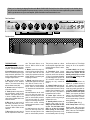
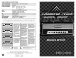
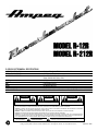
R-12R/R-212R TECHNICAL SPECIFICATIONS
OUTPUT POWER RATING
SIGNAL TO NOISE RATIO
POWER REQUIREMENTS
50 Watts RMS @ 10 % THD 8 ohm load 120 VAC
65dB Typical
Domestic: 100/120 VAC, 60 Hz, 115VA
Export: 220/240 VAC, 50 Hz, 115VA
60 dB Clean channel, 95 dB Overdrive channel
24 dB Range @ 5 kHz Clean channel, 24 dB Range @2kHz Overdrive Channel
8 dB Range @ 700 Hz
24 dB Range @ 40 Hz
12”, 50 w, 8 ohm, 1.5” voice coil diameter, 34 oz. magnet (R-12R = 1, R-212R = 2)
R-12R: 24” W x 19” H x 11” D, 45 lbs.
R-212R: 27.75”W x 19” H x 12”D, 55 lbs.
GAIN
TREBLE
MID
BASS
SPEAKER SPECS
SIZE AND WEIGHT
CAUTION
ATTENTION
VORSICHT
RISK OF ELECTRIC SHOCK
DO NOT OPEN
RISQUE D'ELECTROCUTION
NE PAS OUVRIR
ELEKTRISCHE SCHLAGGEFAHR
NICHT OFFENEN
CAUTION: TO REDUCE THE RISK OF ELECTRIC SHOCK,
DO NOT REMOVE COVER.
NO USER-SERVICEABLE PARTS INSIDE.
REFER SERVICING TO QUALIFIED SERVICE PERSONNEL.
ATTENTION: POUR REDUIRE D'ELECTROCUTION NE PAS
ENLEVER LE COUVERCLE. AUCUNE PIECE INTERNE N'EST REPRABLE
PAR L'UTILISATEUR. POUR TOUTE REPARATION, S'ADRESSER A UN
TECHNICIEN QUALIFIE.
VORSICHT: ZUR MINIMIERUNG ELEKTRISCHER SCHLAGGEFAHR NICHT
DEN DECKEL ABENHMEN. INTERNE TEILE KONNEN NICHT VOM
BENUTZER GEWARTET WERDEN. DIE WARTUNG IS QUALIFIZIERTEM
WARTUNGSPERSONAL ZU UBERLASSEN.
THIS EQUIPMENT HAS BEEN DESIGNED AND ENGINEERED TO PROVIDE SAFE AND RELIABLE OPERATION. IN ORDER TO PROLONG THE LIFE OF
THE UNIT AND PREVENT ACCIDENTAL DAMAGES OR INJURY, PLEASE FOLLOW THESE PRECAUTIONARY GUIDELINES:
CAUTION: TO REDUCE THE RISK OF ELECTRIC SHOCK, DO NOT OPEN CHASSIS; DO NOT DEFEAT OR REMOVE THE GROUND PIN OF THE POWER
CORD; CONNECT ONLY TO A PROPERLY GROUNDED AC POWER OUTLET.
WARNING: TO REDUCE THE RISK OF FIRE OR ELECTRIC SHOCK, DO NOT EXPOSE THIS EQUIPMENT TO RAIN OR MOISTURE.
CAUTION: NO USER-SERVICEABLE PARTS INSIDE. REFER SERVICING TO QUALIFIED SERVICE PERSONNEL.
CAUTION: IF YOU USE AUDIO AMPLIFIERS PROFESSIONALLY OR IN WORK RELATED SITUATIONS AS AN EMPLOYEE, THE OCCUPATIONAL SAFETY
AND HEALTH ADMINISTRATION (OSHA) HAS SPECIFIED REGULATIONS CONCERNING PROLONGED EXPOSURE TO HIGH SOUND PRESSURE LEVELS. PLEASE REFER TO THE CODE OF FEDERAL REGULATIONS DOCUMENT 29CFR1910 FOR ADDITIONAL INFORMATION.
EXPLANATION OF
GRAPHICAL SYMBOLS:
?O2@@@@@@@@@@@@@@@@6X?hf
W2@@@@@@@@@@@@@@@@@@@@@@)Xhf
?O&@@@@@@@@@@@@@@@@@@@@@@@@)X?he
@@@@@@@@@@@@@@@@@@@@@@@@@@@@)Xhe
?J@@@@@@@@@@@@@@@@@@@@@@@@@@@@@1he
W&@@@@@@@@@@@@@@@@@@@@@@@@@@@@@@e?O2@(?e
7@@@@@@@@@@@@@@@@?@@@@@@@@@@@@@@@@@@@(Y?e
?J@@@@@@@@@@@@@@@@5?3@@@@@@@@@@@@@@@@@@Hf
?7@@@@@@@@@@@@@@@@H?N@@@@@@@@@@@@@@@@@5?f
J@@@@@@@@@@@@@@@@5e?3@@@@@@@@@@@@@@@(Y?f
?W&@@@@@@@@@@@@@@@(Ye?N@@@@@@@@@@@@@@@Hg
?7@@@@@@@@@@@@@@@@H?f3@@@@@@@@@@@@@5?g
?3@@@@@@@@@@@@@@@5g?@@@@@@@@@@@@(Y?g
?V4@@@@@@@@@@@@@@Hf?O&@@@@@@@@@@@(Yh
?I4@@@@@@@@@@@5?e?O2@@@@@@@@@@@@@H?h
?I'@@@@@@@@(Y?e@@@@@@@@@@@@@@@5eO2@@f
'@@@@@@@6KfS@@@@@@@@Hf@@@@@@@@@@@@@@@UO2@@@@L?e
V'@@@@@@@@@@@@@UI4@@@@5?
V@@@@@@@1?e
?V'@@@@@@@@@@@@1eI'@@H?
O2@@@@@@@@@Le
V'@@@@@@@@@@@@L??V4@
W2@@@@@@@@@@@1e
?N@@@@@@@@@@@@)X
?O&@@@@@@@@@@@@@L?
?J@@@@@@@@@@@@@1
@@@@@@@@@@@@@@@@1?
?7@@@@@@@@@@@@@@L?
N@@@@@@@@@@@@@@@@?
J@@@@@@@@@@@@@@@1?
?3@@@@@@@@@@@@@@@@
7@@@@@@@@@@@@@@@@L
?N@@@@@@@@@@@@@@@@
@@@@@@@@@@@@@@@@@1
3@@@@@@@@@@@@@@@
@@@@@@@@@@@@@@@@@@L?
N@@@@@@@@@@@@@@@
@@@@@@@@@@@@@@@@@@1?
?3@@@@@@@@@@@@@@
@@@@@@@@@@@@(M?I4@@L
?N@@@@@@@@@@@@@@
3@@@@@@@@@@@H?e?I4@hfW&f3@@@@@@@@@@@@V
N@@@@@@@@@@5
7@fV'@@@@@@@@@@5?
?3@@@@@@@@(Y
?J@@f?N@@@@@@@@@@e
?V'@@@@@@@H?
W&@@g3@@@@@@@@@1?
N@@@@@@@=?
7@@@gN@@@@@@@@@5?
?3@@@@@V@@@@@@@@@@@@@@@@e?J@@@@g?3@@@?@@@(Y?
?N@@@@@@@@@@@@@@@@@@@@@@eW&@@@@@@6Ke?V@@@@@@@He
3@@@@@@@@@@@@@@@@@@@@@e7@@@@@@@@@@@@@@@@@@@5?e
N@@@?@@@@@@@@@@@@@@@@@?J@@@@@@@@@@@@@@@@@@@(Y?e
?3@@?@@@@@@@@@@@@@@@@@W&@@@@@@@@@@@@@@@@@@@Hf
?3@@?@@@@@@@@@@@@@@@@@W&@??@@@@@e@@@??@@@@Hf
?N@@?@@@@@@@@@@@@@@@@@@@@@@@@@@@@@@@@@@@@@@Lf
?N@@T@@@@@@@@@@@@@@@@@@@@??@@@@@e@@@??@@@@Lf
3@@@@@@@@@@@@@@@@@@@@@@@@@@@@@@@@@@@@@@@@)X?e
(R+Me?I@MfI@MI@M
?@M?@)X?e
N@@@@@@@@@@@@@@@@@@@@@@@@@@@@@@@@@@@@@@@@@1?e
?J@@1?e
?@@@@@@@@@@@@@@@@@@@@@@@@@@@@@@@@@@@@@@@@@@?e
?W-Xg@@@@g@@@?h@?fW&@@@?e
?@V'@@@@@@@@@@@@@@@@?@@@@@@@@@@@@@@@@@@@@@5?e
?7R/hf?@
@?e?W&@@@5?e
?@?V'@@@@@@@@@@@@@@@@@@@@@@@@@@@@@@@@@@@@(Y?e
?@f?W-XeW&e?@?O@K
?&@@@(Y?e
?@eV'@@@@@@@@@@@@@@@@@@@@@@@@@@@@@@(MI40Yf
?@fW&@)KO&5eJ@@@@@6KO@KO@Ke?O)XeI40Yf
?V4@@@@@@@@@@@@@?I'@@@@@@@@@@@@(Y?h
&@@@@@@??W&@@@?I'@@@@@@@@@@@@,he
?I4@@@@@@@@@@@eN@@@@@@@@@@@0Yhe
?I4@@@@@?&@@@@eN@@@@@@@@@@@0Yhe
?3@@@(M?
?N@@@H
3@@?
N@@?
?3@?
?V'?
"DANGEROUS VOLTAGE"
= "DANGER HAUTE TENSION"
"GEFAHLICHE SPANNUNG"
"IT IS NECESSARY FOR THE USER TO REFER TO THE INSTRUCTION MANUAL"
= "REFERREZ-VOUS AU MANUAL D'UTILISATION"
"UNBEDINGT IN DER BEDIENUNGSANLEITUNG NACHSCHLAGEN"
Specs and other information subject to change without notice.
Ampeg is proudly Made in America. ©1997 SLM Electronics, 1400 Ferguson Avenue, St. Louis, MO 63133 U.S.A.
47-278-01 • 10-97
Thank you for selecting the Ampeg Reverberocket Model R-12R/R-212R. Revived from the sixties and ready for the nineties, these
easy-to-use two-channel amplifiers represent Ampeg’s quest to provide you the finest instrument amplification systems available. In
order to get the most out of your new amplifier, please read these instructions before its use.
The Front Panel:
MODEL R-12R
Made in the U.S.A.
4
5
6
4
3
7
13
9
2
1
2
GUITAR ACCORDION
8
10
0
GAIN
5
6
4
3
7
14
9
2
8
0
10
6
4
3
7
15
9
2
8
0
VOLUME
5
10
5
4
3
7
16
9
2
8
10
0
TREBLE
6
MID
CLEAN CHANNEL
5
6
4
3
7
17
9
2
8
10
0
BASS
5
6
3
7
18
9
2
8
0
10
MASTER
BOTH CHANNELS
4
5
6
STANDBY
3
7
19
9
2
OFF
8
0
10
11
10
REVERB
LINE OUT
LINE IN
12
13
14
FOOTSWITCH CHANNEL
CH. / REV.
SELECT
15
ON
16
ON
BOTH CHANNELS
OVERDRIVE CHANNEL
yy
;;
;;;;;;;;;;;;;;;;;;;;;;;;;;;;;;;;;;yy
yyyyyyyyyyyyyyyyyyyyyyyyyyyyyyyyyy
;;
;;
yy
;;;;;;;;;;;;;;;;;;;;;;;;;;;;;;;;;;yy
yyyyyyyyyyyyyyyyyyyyyyyyyyyyyyyyyy
;;
;;
yy
;;;;;;;;;;;;;;;;;;;;;;;;;;;;;;;;;;yy
yyyyyyyyyyyyyyyyyyyyyyyyyyyyyyyyyy
;;
;;
yy
;;
yy
;;
yy
;;
yy
;;
yy
;;
yy
;;
yy
;;
yy
;;
yy
;;
yy
The Rear Panel:
17
THE FRONT PANEL:
1. Guitar Input accepts a standard
1/4” instrument plug from your electric guitar. This input is at 0dB level.
2. Accordion Input accepts a standard 1/4” instrument plug from high
output electronic instruments. This
input is padded 6dB to compensate
for higher output sources.
3. Gain sets the amount of overdrive distortion for the overdrive
channel. This control works along
with the Master control (#8).
4. Volume controls the output level
of the clean channel.
5. Treble adjusts the output level of
the high frequency range for both
channels. This control offers a cut
or boost of 24dB at 5kHz for the
clean channel, 24dB at 2kHz for the
overdrive channel.
6. Mid adjusts the output level of
the middle frequencies for both
channels. This control offers a cut
or boost of 8dB at 700Hz for both
channels.
7. Bass adjusts the output level of
the low frequencies for both chan-
18
nels. This control offers a cut or
boost of 24dB at 40Hz for both
channels.
8. Master controls the output volume level of the overdrive channel.
This control works with the Gain
control (#3) to produce sounds from
slightly distorted to screaming and
everything in between.
9. Reverb controls the amount of
reverberation applied to both channels. With the control at the “0”
position there is no reverb applied;
as the control is turned towards
“10” the amount of reverb increases
accordingly.
10. Line Out serves as the “send”
jack of an effect loop, when connected to the input jack of a floor
pedal or rack-mounted processor.
This jack can double as a signal
output for connecting directly to a
house sound console, recording
console, powered monitor or external amplifier.
11. Line In serves as the “return”
jack of an effect loop, when connected to the output jack of a floor
pedal or rack-mounted processor.
19
20
21
This jack can double as a directinto-the amplifier signal feed when
using the amp as a “slave” or extension amplifier.
12. Footswitch allows “remote
control” of the channel selection
and reverb on/off. Insert the stereo
1/4” plug of a two-button footswitch
(such as Ampeg’s AFP-2) here. The
“tip” connection controls channel
switching, the “ring” controls the
reverb.
13. Channel Select activates the
clean channel in the down position
and the overdrive channel in the up
position. When a footswitch is connected (see #12), this switch is
bypassed and has no affect.
14. Power light indicates the
amplifier is turned on by glowing an
iridescent blue color.
15. Standby switch activates the
amplifier when ready for play.
Always turn this switch off first,
on last. Turn the Power switch
(#16) on at least 30 seconds
before turning on the Standby
switch. During short breaks of use,
turn the Standby switch off, leaving
22
the Power switch on. This will help
prolong the life of the amplifier’s
tubes.
16. Power switch turns the main
power on and off. Always turn this
switch on first, off last. Turn the
Standby switch (#15) on at least
30 seconds after turning on the
Power switch.
THE REAR PANEL:
17. Power cord connects the
amplifier to a suitable source of
A.C. voltage. This is a grounded,
three-wire cord and must be connected to a properly grounded outlet. DO NOT attempt to defeat the
ground connection of the power
cord! If your amp was purchased
outside of the United States, see
the sticker next to the A.C. connector for its power ratings. Follow the
above guidelines.
18, 19. Power Tubes: 6L6 (2)
20-22. Preamp Tubes: 12AX7A (3)
Replace tubes ONLY with same
types! Refer to enclosed publication
about Tubes and Tube Amplifiers
for additional information.