1
AIR CONDITIONERS CITY MULTI Series Y, Super Y
Models
PUHY-400YMF-B, 500YMF-B
PUHY-P400YMF-B, P500YMF-B
PUHY-600YSMF-B, 650YSMF-B, 700YSMF-B, 750YSMF-B
PUHY-P600YSMF-B, P650YSMF-B, P700YSMF-B, P750YSMF-B
Service Handbook
Contents
1 PRECAUTIONS FOR DEVICES
THAT USE R407C REFRIGERANT ......................................... 1
[1] Storage of Piping Material ............................................. 2
[2] Piping Machining ........................................................... 3
[3] Necessary Apparatus and Materials and Notes on
Their Handling ............................................................... 4
[4] Brazing ........................................................................... 5
[5] Airtightness Test ............................................................. 6
[6] Vacuuming ..................................................................... 6
[7] Charging of Refrigerant ................................................. 7
[8] Dryer .............................................................................. 7
2 COMPONENT OF EQUIPMENT ............................................. 8
[1] Appearance of Components .......................................... 8
[2] Refrigerant Circuit Diagram and Thermal Sensor ........ 18
[3] Equipment Composition ............................................... 22
[4] Electrical Wiring Diagram ............................................. 24
[5] Standard Operation Data ............................................. 27
[6] Function of Dip SW and Rotary SW ............................ 39
3 TEST RUN ............................................................................. 45
[1] Before Test Run ........................................................... 45
[2] Test Run Method .......................................................... 52
4 GROUPING REGISTRATION OF INDOOR UNITS WITH
REMOTE CONTROLLER ...................................................... 53
5 CONTROL .............................................................................. 59
[1] Control of Outdoor Unit ................................................ 59
[2] Operation Flow Chart ................................................. 109
[3] List of Major Component Functions ........................... 114
[4] Resistance of Temperature Sensor ............................ 118
6 REFRIGERANT AMOUNT ADJUSTMENT ......................... 119
[1] Operating Characteristics and Refrigerant Amount ... 119
[2] Adjustment and Judgement of Refrigerant Amount ... 119
[3] Refrigerant Volume Adjustment Mode Operation ....... 122
7 TROUBLESHOOTING ......................................................... 129
[1] Principal Parts ............................................................ 129
[2] LED monitor display and Countermeasures
Depending on the Check Code Displayed ................. 158
[3] LED Monitor Display .................................................. 179
Safety precautions
Before installation and electric work
s Before installing the unit, make sure you read all
the “Safety precautions”.
s The “Safety precautions” provide very important
points regarding safety. Make sure you follow them.
s This equipment may not be applicable to EN610003-2: 1995 and EN61000-3-3: 1995.
s This equipment may have an adverse effect on
equipment on the same electrical supply system.
s Please report to or take consent by the supply authority before connection to the system.
•
•
•
•
•
•
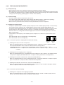
Symbols used in the text
Warning:
Describes precautions that should be observed to prevent danger of injury or death to the user.
Caution:
Describes precautions that should be observed to prevent damage to the unit.
•
•
Symbols used in the illustrations
: Indicates an action that must be avoided.
•
: Indicates that important instructions must be followed.
: Indicates a part which must be grounded.
: Indicates that caution should be taken with rotating parts. (This
symbol is displayed on the main unit label.) <Color: Yellow>
: Indicates that the main switch must be turned off before servicing. (This symbol is displayed on the main unit label.) <Color:
Blue>
•
: Beware of electric shock (This symbol is displayed on the main
unit label.) <Color: Yellow>
: Beware of hot surface (This symbol is displayed on the main
•
unit label.) <Color: Yellow>
ELV : Please pay attention to electric shock fully because
this is not Safety Extra Low-Voltage (SELV) circuit.
And at servicing, please shut down the power supply
for both of Indoor Unit and Outdoor Unit.
•
•
Warning:
Carefully read the labels affixed to the main unit.
•
•
•
Warning:
Ask the dealer or an authorized technician to install the air
conditioner.
- Improper installation by the user may result in water leakage,
electric shock, or fire.
Install the air unit at a place that can withstand its weight.
- Inadequate strength may cause the unit to fall down, resulting
in injuries.
Use the specified cables for wiring. Make the connections
securely so that the outside force of the cable is not applied
to the terminals.
- Inadequate connection and fastening may generate heat and
cause a fire.
Prepare for typhoons and other strong winds and earthquakes and install the unit at the specified place.
- Improper installation may cause the unit to topple and result in
injury.
Always use an air cleaner, humidifier, electric heater, and
other accessories specified by Mitsubishi Electric.
- Ask an authorized technician to install the accessories. Improper
installation by the user may result in water leakage, electric
shock, or fire.
Never repair the unit. If the air conditioner must be repaired,
consult the dealer.
- If the unit is repaired improperly, water leakage, electric shock,
or fire may result.
Do not touch the heat exchanger fins.
- Improper handling may result in injury.
If refrigerant gas leaks during installation work, ventilate the
room.
- If the refrigerant gas comes into contact with a flame, poisonous gases will be released.
Install the air conditioner according to this Installation
Manual.
- If the unit is installed improperly, water leakage, electric shock,
or fire may result.
Have all electric work done by a licensed electrician according to “Electric Facility Engineering Standard” and “Interior
Wire Regulations”and the instructions given in this manual
and always use a special circuit.
- If the power source capacity is inadequate or electric work is
performed improperly, electric shock and fire may result.
Securely install the cover of control box and the panel.
- If the cover and panel are not installed properly, dust or water
may enter the outdoor unit and fire or electric shock may result.
When installing and moving the air conditioner to another
site, do not charge the it with a refrigerant different from the
refrigerant (R22/R407C) specified on the unit.
- If a different refrigerant or air is mixed with the original refrigerant, the refrigerant cycle may malfunction and the unit may be
damaged.
If the air conditioner is installed in a small room, measures
must be taken to prevent the refrigerant concentration from
exceeding the safety limit even if the refrigerant should leak.
- Consult the dealer regarding the appropriate measures to prevent the safety limit from being exceeded. Should the refrigerant leak and cause the safety limit to be exceeded, hazards
due to lack of oxygen in the room could result.
When moving and reinstalling the air conditioner, consult
the dealer or an authorized technician.
- If the air conditioner is installed improperly, water leakage, electric shock, or fire may result.
After completing installation work, make sure that refrigerant gas is not leaking.
- If the refrigerant gas leaks and is exposed to a fan heater, stove,
oven, or other heat source, it may generate noxious gases.
Do not reconstruct or change the settings of the protection
devices.
- If the pressure switch, thermal switch, or other protection device is shorted and operated forcibly, or parts other than those
specified by Mitsubishi Electric are used, fire or explosion may
result.
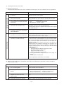
1 PRECAUTIONS FOR DEVICES THAT USE R407C REFRIGERANT
Caution
Do not use the existing refrigerant piping.
Use a vacuum pump with a reverse flow check valve.
•
•
The old refrigerant and refrigerator oil in the existing
piping contains a large amount of chlorine which may
cause the refrigerator oil of the new unit to deteriorate.
Do not use the following tools that have been used
with conventional refrigerants.
(Gauge manifold, charge hose, gas leak detector, reverse flow check valve, refrigerant charge base,
vacuum gauge, refrigerant recovery equipment)
Use refrigerant piping made of C1220 (CU-DHP) phosphorus deoxidized copper as specified in the *JIS
H3300 “Copper and copper alloy seamless pipes and
tubes”. In addition, be sure that the inner and outer
surfaces of the pipes are clean and free of hazardous
sulphur, oxides, dust/dirt, shaving particles, oils,
moisture, or any other contaminant.
•
•
If the conventional refrigerant and refrigerator oil are
mixed in the R407C, the refrigerant may deteriorated.
• If water is mixed in the R407C, the refrigerator oil
may deteriorate.
• Since R407C does not contain any chlorine, gas
leak detectors for conventional refrigerants will not
react to it.
Contaminants on the inside of the refrigerant piping
may cause the refrigerant residual oil to deteriorate.
*JIS: Japanese Industrial Standard
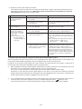
Store the piping to be used during installation indoors
and keep both ends of the piping sealed until just
before brazing. (Store elbows and other joints in a
plastic bag.)
•
Do not use a charging cylinder.
•
If dust, dirt, or water enters the refrigerant cycle,
deterioration of the oil and compressor trouble may
result.
Use ester oil, ether oil or alkylbenzene (small
amount) as the refrigerator oil to coat flares and
flange connections.
The refrigerator oil will degrade if it is mixed with a
large amount of mineral oil.
Use liquid refrigerant to seal the system.
If gas refrigerant is used to seal the system, the composition of the refrigerant in the cylinder will change
and performance may drop.
Do not use a refrigerant other than R407C.
•
If dust, dirt, or water gets in the refrigerant cycle, the
refrigerant may deteriorate.
If the refrigerant leaks, recover the refrigerant in the
refrigerant cycle, then recharge the cycle with the
specified amount of the liquid refrigerant indicated
on the air conditioner.
•
•
Using a charging cylinder may cause the refrigerant
to deteriorate.
Be especially careful when managing the tools.
•
•
The vacuum pump oil may flow back into the refrigerant cycle and cause the refrigerator oil to deteriorate.
If another refrigerant (R22, etc.) is used, the chlorine
in the refrigerant may cause the refrigerator oil to deteriorate.
–1–
Since R407C is a nonazeotropic refrigerant, if additionally charged when the refrigerant leaked, the composition of the refrigerant in the refrigerant cycle will
change and result in a drop in performance or abnormal stopping.
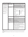
[1] Storage of Piping Material
(1) Storage location
Store the pipes to be used indoors. (Warehouse at site or owner’s warehouse)
Storing them outdoors may cause dirt, waste, or water to infiltrate.
(2) Pipe sealing before storage
Both ends of the pipes should be sealed until immediately before brazing.
Wrap elbows and T’s in plastic bags for storage.
* The new refrigerator oil is 10 times more hygroscopic than the conventional refrigerator oil (such as Suniso). Water
infiltration in the refrigerant circuit may deteriorate the oil or cause a compressor failure. Piping materials must be
stored with more care than with the conventional refrigerant pipes.
–2–
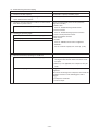
[2] Piping Machining
Use ester oil, ether oil or alkylbenzene (small amount) as the refrigerator oil to coat flares and flange connections.
Use only the necessary minimum quantity of oil !
Reason:
1. The refrigerator oil used for the equipment is highly hygroscopic and may introduce water inside.
Notes:
• Introducing a great quantity of mineral oil into the refrigerant circuit may also cause a compressor failure.
• Do not use oils other than ester oil, ether oil or alkylbenzene.
–3–
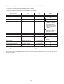
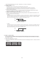
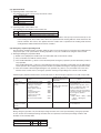
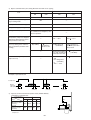
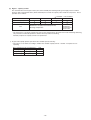
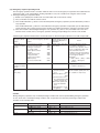
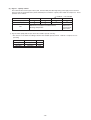
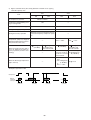
[3] Necessary Apparatus and Materials and Notes on Their Handling
The following tools should be marked as dedicated tools for R407C.
<<Comparison of apparatus and materials used for R407C and for R22>>
Apparatus Used
Use
R22
Gauge manifold
Charging hose
Charging cylinder
Gas leakage detector
Refrigerant collector
Refrigerant cylinder
Evacuating, refrigerant filling
Operation check
Refrigerant charging
Gas leakage check
Refrigerant collection
Refrigerant filling
Current product
Current product
Current product
Current product
R22
R22
Vacuum pump
Vacuum drying
Current product
Vacuum pump with a check valve
Flare tool
Bender
Application oil
Flaring of pipes
Bending of pipes
Applied to flared parts
Current product
Current product
Current product
Current product
Torque wrench
Pipe cutter
Welder and nitrogen cylinder
Refrigerant charging meter
Vacuum gauge
Tightening of flare nuts
Cutting of pipes
Welding of pipes
Refrigerant charging
Checking the vacuum degree
Current product
Current product
Current product
Current product
Current product
Symbols:
To be used for R407C only.
R407C
Do not use.
Shared with R134a
For R407C use only
Identification of dedicated use for R407C
: Record refrigerant
name and put brown
belt on upper part of
cylinder.
Can be used by
attaching an adapter
with a check valve.
Ester oil or Ether oil or
Alkybenzene (Small
amount)
Can also be used for conventional refrigerants.
Tools for R407C must be handled with more care than those for conventional refrigerants. They must not come into contact
with any water or dirt.
–4–
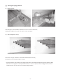
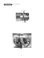
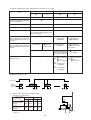
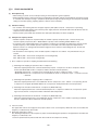
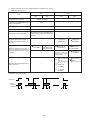
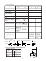
[4] Brazing
No changes from the conventional method, but special care is required so that foreign matter (ie. oxide scale, water, dirt,
etc.) does not enter the refrigerant circuit.
Example: Inner state of brazed section
When non-oxide brazing was not used
When non-oxide brazing was used
Items to be strictly observed:
1. Do not conduct refrigerant piping work outdoors on a rainy day.
2. Apply non-oxide brazing.
3. Use a brazing material (Bcup-3) which requires no flux when brazing between copper pipes or between a copper pipe
and copper coupling.
4. If installed refrigerant pipes are not immediately connected to the equipment, then braze and seal both ends of them.
Reasons:
1. The new refrigerant oil is 10 times more hygroscopic than the conventional oil. The probability of a machine failure if
water infiltrates is higher than with conventional refrigerant oil.
2. A flux generally contains chlorine. A residual flux in the refrigerant circuit may generate sludge.
Note:
• Commercially available antioxidants may have adverse effects on the equipment due to its residue, etc. When
applying non-oxide brazing, use nitrogen.
–5–
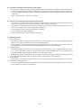
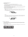
[5] Airtightness Test
No changes from the conventional method. Note that a refrigerant leakage detector for R22 cannot detect R407C
leakage.
Halide torch
R22 leakage detector
Items to be strictly observed:
1. Pressurize the equipment with nitrogen up to the design pressure and then judge the equipment’s airtightness, taking
temperature variations into account.
2. When investigating leakage locations using a refrigerant, be sure to use R407C.
3. Ensure that R407C is in a liquid state when charging.
Reasons:
1. Use of oxygen as the pressurized gas may cause an explosion.
2. Charging with R407C gas will lead the composition of the remaining refrigerant in the cylinder to change and this
refrigerant can then not be used.
Note:
• A leakage detector for R407C is sold commercially and it should be purchased.
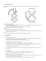
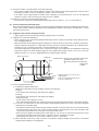
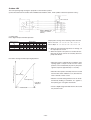
[6]
Vacuuming
1. Vacuum pump with check valve
A vacuum pump with a check valve is required to prevent the vacuum pump oil from flowing back into the refrigerant
circuit when the vacuum pump power is turned off (power failure).
It is also possible to attach a check valve to the actual vacuum pump afterwards.
2. Standard degree of vacuum for the vacuum pump
Use a pump which reaches 0.5 Torr (500 MICRON) or below after 5 minutes of operation.
In addition, be sure to use a vacuum pump that has been properly maintained and oiled using the specified oil. If the
vacuum pump is not properly maintained, the degree of vacuum may be too low.
3. Required accuracy of the vacuum gauge
Use a vacuum gauge that can measure up to 5 Torr. Do not use a general gauge manifold since it cannot measure a
vacuum of 5 Torr.
4. Evacuating time
• Evacuate the equipment for 1 hour after – 755 mmHg (5 Torr) has been reached.
• After envacuating, leave the equipment for 1 hour and make sure the that vacuum is not lost.
5. Operating procedure when the vacuum pump is stopped
In order to prevent a backflow of the vacuum pump oil, open the relief valve on the vacuum pump side or loosen the
charge hose to drawn in air before stopping operation.
The same operating procedure should be used when using a vacuum pump with a check valve.
–6–
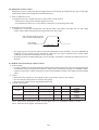
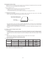
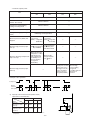
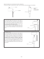
[7] Charging of Refrigerant
R407C must be in a liquid state when charging, because it is a non-azeotropic refrigerant.
For a cylinder with a syphon attached
For a cylinder without a syphon attached
Cylinder
Cylinder
Cylinder color identification
R407C-Gray
R410A-Pink
Charged with liquid refrigerant
Valve
Valve
Liquid
Liquid
Reasons:
1. R407C is a mixture of 3 refrigerants, each with a different evaporation temperature. Therefore, if the equipment is
charged with R407C gas, then the refrigerant whose evaporation temperature is closest to the outside temperature is
charged first while the rest of refrigerants remain in the cylinder.
Note:
• In the case of a cylinder with a syphon, liquid R407C is charged without turning the cylinder up side down. Check the
type of cylinder before charging.
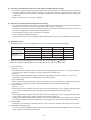
[8] Dryer
1. Replace the dryer when the refrigerant circuit is opened (Ex. Change the compressor, full gas leakage). Be sure to
replace the dryer with a CITY MULTI Series Y, Super Y (For use with R407C).
If any other product is used, the unit will be damaged.
2. Opening the refrigerant circuit after changing to a new dryer is less than 1 hour. The replacement of the dryer should
be the last operation performed.
–7–
2 COMPONENT OF EQUIPMENT
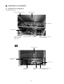
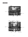
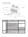
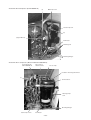
[1] Appearance of Components
1 Variable capacity unit
Ambient temperature Sensor
Heat Exchanger
Accumulator
Oil Separator
Variable Capacity
Compressor (No.1
Compressor)
Oil Equalization Pipe
Belt Heater
Constant Capacity Compressor
(No.2 Compressor)
Rear
Heat Exchanger
Four-way Valve
(21S4a)
Sub-cool Ciol
Four-way Valve
(21S4b)
Solenoid Valve Heat Exchanger of CS circuit
(SV5b)
(PUHY-P-YMF-B only)
–8–
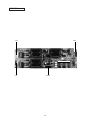
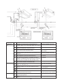
Controller Box
RELAY board
FANCON board
Choke coil (L2)
MAIN board
Magnetic contactor
(52C2)
INV board
Thyristor module
(SCRM)
Thermal overload
(51C2)
Transistor module
(TRM)
Diode stack (DS)
Magnetic contactor
(52F)
–9–
Magnetic contactor Capacitor (C2, C3)
(52C1)
(Smoothing capacitor)
Noise Filter Box
(Rear of the controller box)
DC reactor (DCL)
Noise filter box
Noise filter (NF)
–10–
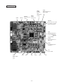
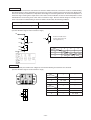
MAIN board
CNTR
CNFC1
CNS1
CNVCC4
M-NET
Power source for
transmission
control
CNS2
M-NET
transmission
(Centralized
control)
CN40
M-NET transmission
power supply
CNVCC3
Power source for control
1-2 30 V, 1-3 30 V
4-6 12 V, 5-6 5 V
CN51
Indication distance
3-4 Compressor
ON/OFF
3-5 Trouble
CNRS3
Serial transmission to
INV board
CN3D
Cooling/Heating auto
changeover
LD1
Service LED
CN20
Power supply
3 L1
1N
SW4
SW3
SW2
–11–
SWU2
SWU1
SW1
INV board
Output to transistor module
CN3
CN2-1 CN2-2
CN2-3
CNVCC2
Power supply (5 V)
CNVCC1
Power supply
1-2 30 V, 1-3 30 V,
4-6 12 V, 5-6 5 V
CNL2
CN30V
CNVDC
CNTH
CN52C
CNCT
CNFAN
CNAC2
Power source
1 L2
3N
CNR
CNRS2
SW1
–12–
FANCON board
CNV
CNU
CNW
CNFC2
–13–
RELAY board
CN51C2
CN52F
CNOUT2
CN52C2
CNRT2
CNCH
–14–
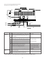
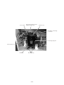
2 Constant capacity unit
Ambient temperature sensor
Solenoid valve (SV3, PUHN-P-YMF-B only)
Solenoid valve (SV2, PUHN-P-YMF-B only)
Heat exchanger
Accumlator
Controller box
Four- way valve
Service check-point
(right; high pressure,
left; low pressure)
Gas ball valve
Liquid ball valve
Constant capacity compressor
(No.3 compressor)
Belt heater
Rear
Heat exchanger
Accumulator
Sub-cool coil
–15–
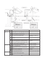
Oil balance pipe
Controller Box
CONT board
Terminal block TB1
powersource
Terminal block TB3
transmission
Transformer
FANCON board
Magnetic contactor
(52C)
Noise Filter (NF)
Thermal overload relay
(51C)
Thyristor module
(SCRM)
Fuses (F1,F2)
–16–
CONT board
SWU1
CNFC1
SW3
SWU2
CNTR
CN20
Power supply
1 N
3 L1
–17–
SW2
CNS1
M-NET
transmission
TH6
HEX1b
–18–
SV5b
HEX1a
TH10a
HEX2a
TH5
HEX2b
TH10b
21S4b
SCC
TH8
CS-circuit
Drier
63H1
CV1
O/S
ST6
TH2
CP4
TH9b CP2
TH10c
SV1
SV6
SV4
TH12
CP3a SV22
ST4
CJ3
TH7
TH4
63H2
CV2
ST7
SLEV
ST5
LEV1
TH9a
CP1
CJ1
63HS
Comp1
TH11
21S4a
Comp2
ST8
SV32
SA
TH3 ST3
ST9
CP3b
CV3
CP5
MA
63LS
CJ2
BV2
ST2
BV3
ST1
BV1
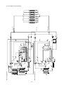
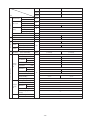
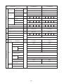
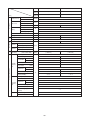
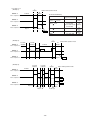
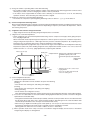
[2] Refrigerant Circuit Diagram and Thermal Sensor
1 PUHY-P400·500YMF-B
TH6
–19–
SV5b
HEX1a
HEX1b
TH10b
TH5
HEX2a
TH10a
HEX2b
21S4b
SCC
TH8
63H1
CV1
O/S
CP4
No.1
Comp.
LEV1
TH9
SV1
CP1
63HS
CJ1
ST6
TH11
21S4a
ST4
TH7
TH4
CJ3
ST8
No.2
Comp.
SV22 SV32
TH12
CP3a
SV6
63H2
CV2
ST7
SLEV
ST5
SV4
TH3
CP3b
ST3
ST9
SA
CV3
CP5
MA
CJ2
TH2
CP2
* There are SV22, SV32 only for PUHY-500YMF-B
ST2
ST1
BV3
BV2
BV1
2 PUHY-400·500YMF-B
SV5b
HEX1a
–20–
TH6
HEX1
TH5
HEX2
TH10a
CV1
SCC
TH8
TH11
21S4
SCC
TH8
O/S
ST6
SV3
SV1
LEV1
TH9
ST10
ST7
ST5
SV6
SV4
ST3
TH7
TH4
TH3
SV4
TH12
CP3a SV22
ST9
ST4
ST4
CJ3
TH7
TH4
63H2
CV2
ST7
SLEV
ST5
LEV1
TH9a
CP1
CP4
Comp1
SV2
ST6
O/S
CJ1
CV1
TH2
TH9b CP2
CP4
TH10c
SV1
CP1
CJ1
63HS
Comp1
TH11
21S4a
CS-circuit
Drier
63H1
63H
TH10a
21S4b
HEX2a
TH5
HEX2b
PUHN-P200,250YMF-B
TH6
HEX1b
TH10b
PUHY-P400,500YMF-B
ST8
ST8
Comp2
SV32
SA
SA
TH3 ST3
ST9
CP3b
CP3
MA
CV3
CP5
MA
LEV2
BV2
BV2
BV1
BV3
ST2
ST1
ST2
BV3
TH10b
SV5b CP5
CV2
63LS
CJ2
63LS
CJ2
ST1
BV1
Distributer(Liquid)
pipe
Oil balance
Indoor unit
Distributer(Gas)
3 PUHY-P600·650·700·750YSMF-B
SV5b
HEX1a
–21–
TH6
HEX1
PUHY-200,250YMF-B
TH6
HEX1b
PUHY-400,500YMF-B
TH5
TH10a
TH5
HEX2b
TH10b
HEX2
SCC
TH8
63H
21S4
SCC
TH8
HEX2a
TH9
ST9
ST4
TH7
ST3
TH3
SV4
TH7
ST4
SV32
ST8
SA
SA
ST3
ST9
CP3b
ST8
TH3
Comp2
SV22
CP3a
TH12
SV6
SV4
63H2
CJ3
CV2
TH4
ST5
ST7
LEV1 ST7
ST10
CP4
Comp1
TH11
CP1
SV1
ST6
O/S
CV1
CJ1
LEV1
ST10
TH4
SLEV
TH9
SV1
CP1
ST5
CJ1
63HS
CP4
Comp1
TH11
ST6
O/S
21S4a
63H1
CV1
TH10a
21S4b
CP3
MA
CP5
CV3
MA
CV2
LEV2
SV5b CP5
BV2
BV1
TH10b
ST2
BV3
BV2
BV3
ST2
ST1
CJ2
63LS
TH2
CP2
CJ2
ST1
BV1
Distributer (Liquid)
Oil balance pipe
Distributer (Gas)
Indoor unit
4 PUHY-600·650·700·750YSMF-B
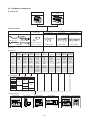
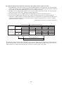
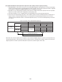
[3] Equipment Composition
A. Outdoor Unit
PUHY-(P)600·650·700·750
YSMF-B
PUHY-(P)400·500YMF-B
B. Branch Pipe Kit
▼
Branch joint
Oil balance pipe 1
Distributer (gas)
Oil balance pipe 2
Distributer (liquid)
CMY-Y102S-F CMY-Y102L-F
CMY-Y202-F CMY-Y302-F
CMC-30A*
4-connection
Branch header
7-connection
10-connection
CMY-Y104-E
CMY-Y107-E
CMY-Y1010-E
In the case of the PUHY-(P)YSMF-B, the CMC-30A is
necessary.
D. Indoor unit
Model
▼
Cassette ceiling
Ceiling mounted
Wall mounted
built-in
Floor standing
1-way flow
2-way flow
4-way flow
Ceiling
concealed
PMFY-P
PLFY-P
PLFY-P
PEFY-P
20
20VMB
20VLMD
-
20VML
PDFY-P
20VM
25
25VBM
25VLMD
-
25VML
25VM
25VAM
-
25VLEM
25VLRM
32
32VBM
32VLMD
32VKM
32VML
32VM
32VGM
-
32VLEM
32VLRM
40
40VBM
40VLMD
40VKM
40VMH
40VM
40VGM
40VGM
40VLEM
40VLRM
50
-
50VLMD
50VKM
50VMH
50VM
50VGM
-
50VLEM
50VLRM
63
-
63VLMD
63VKM
63VMH
63VM
-
63VGM
63VLEM
63VLRM
71
80
-
80VLMD
80VKM
71VMH
80VMH
71VM
80VM
-
-
-
-
100
-
100VLMD
100VKM
100VMH
100VM
-
-
-
125VLMD
125VKM
125VMH
125VM
-
100VGM
125VGM
-
125
-
-
140
200
-
-
-
140VMH
200VMH
-
-
-
-
-
250
-
-
-
250VMH
-
-
-
-
-
Capacity
Ceiling
suspended
Exposed
PKFY-P
PCFY-P
PFFY-P
PFFY-P
20VAM
-
20VLEM
20VLRM
Concealed
E. Option (panel)
Model
Decoration panel
Capacity
PMP-
CMP-
PLP-
20
25
40MB
32
40
-
32LW-F
40LW-F
50
63
-
80
100, 125
3GB
63LW-F
125LW-F
6GB
F. Remote controller
PAR-F25MA
PAC-FL31MA
CHECK
PAC-SC30GRA
MJ-103MTRA
PAC-SC32PTA
PAC-SE51CRA
TEST RUN
˚C
ON/OFF
AM
PM
ON/OFF –
CENTRALLY CONTROLLED
ON
CHECK
1Hr.
OFF
INDOOR UNIT
ADDRESS NO.
CHECK ADDRESS
NOT AVAILABLE
ON
˚C
OFF
˚C
FAN SPEED
GROUP
SELECT
3
AIR
DIRECTION
TEMP.
ON/OFF
CENTRAL CONTROLLER
MJ-103MTRA
REMOTE
PROHIBITION
0
6
5
7
FILTER
FAN
CLOCK/
PATTERN
VANE
STOP
START
HR.
MIN.
GROUP
REMOTE CONTROLLER
PAC-SC30GRA
GROUP
3
6
9
12
15
18
21
24
VENTILATION
9
8
TIMER
MODE
BACK
SCREEN
INS.
SET/MONITOR
RESET
DEL.
TODAY
WEEKLY
SETTING
SET BACK
ON
DAILY
SETTING
ENTER
CHECK
FILTER
CHECK
CENTRAL TEMP.CHECK
0
12
˚C
MODE
2
TEMP.
CLOCK ON OFF
TIMER SET
ON/OFF
1
4
CLOCK
BACK
S M T W T F S
TEST RUN
TEST RUN
MODE
TEMP.
SET
SET
ON/OFF
FILTER
CHECK MODE
TEST RUN
NOT AVAILABLE
ON/OFF
CHECK MODE
ERROR CODE
OA UNIT ADDRESS NO.
CENTRALLY CONTROLLED
COLLECTIVE
GROUP
FILTER
˚C
STAND BY
DEFROST
AM
PM
NOT AVAILABLE
˚C
CLOCK
CLOCK
PROGRAM TIMER
PAC-SC32PTA
OFF
ON/OFF
SET BACK
ON
TEST RUN
DAILY TIMER
OFF
TEMP.
TEST RUN
NETWORK
REMOTE CONTROLLER
PAR-F25MA
PAC-SE51CRA
–22–
–23–
52F
CH12
A2
CN51C2
(3P)
3
2
1
CNCH
(3P)
3
2
1
CN52F
(3P)
5
4
1
2
3
CN52C2
(5P)
3
2
1
M1
X03
X02
X01
CNOUT2
(4P)
CNRT2
(5P)
RELAY board
BOX BODY
S
M2
M1
TB7
M2
SV5b
21S4b
CH2
CH3
21S4a
SV1
Red
3
6
5
4
3
2
1
6
5
4
3
2
1
3
2
1
6
5
4
3
2
1
1
2
3
1
2
4
3
2
1
1
X10
X09
X08
X07
X06
4 3
1 2
SSR
X05
X04
X02
X01
N
L3
L2
CN05
(4P)
12
*2
2
3
CNTR
(3P)
OFF
ON
SW4-6
F3
250VAC
1A F
VK2
VG2
VK1
VG1
~-
~
~+
DS
F2
600VAC
12A F
White
L3 Black
L2
L1
Red
CN03
(3P)
TH6
123
CN02
(8P)
TH5 TH8 TH2
TH7
12345678
K G
UK1
SCRM
UG1
1
2
1
2
3
W
V
1
2
3
4
5
*2
63LS
63HS
LEV1
3 2 1
3 2 1
TH11
SLEV
CNLV2
(5P)
12345
CNLV1
(5P)
12345
CNL
(3P)
1 2 3
1 2 3
12
CN01 CNH
(2P) (3P)
4
5
6
1
CN3N 3
(3P) 21
CN3S 3
(3P) 21
1 2 3 4
3
2
1
1
2
3
4
5
6
6
1234
(3P)
5
2
CNU 3
(5P) 4
CNV
(5P)
5 4 3 2 1
CNW
(5P)
CNFC2
(6P)
5 4 3 2 1
1
2
3
4
5
6
C15
2 1
CN2-2
(2P)
CNR
(3P)
1 2 3
UK2
UG2
UK1
UG1
HEAT
COOL
2 1
R6
L2
BOX BODY
FG
CN3
(6P)
1 2 3 4 5 6
C25
Magnetic contactor
SSR
FB1
Earth terminal
Ferrite core
Choke coil(Transmission)
Power transistor module
TRM1~3
High pressure switch
L2
Electronic expansion valve
63HS,63LS
Solenoid valve
4-way valve
Solid state relay
LEV1,SLEV
SV1,22,32,4,5b,6
21S4a,b
Fan (Radiator panel)
52F
MF1
Magnetic contactor
Overload Relay
52C2
52C1
51C2
Varistor
Magnetic contactor (Inverter main circuit)
ZNR4
DC reactor (Power factor improvement)
Current Sensor
DCL
DCCT
High pressure switch
Cord heater
63H1,2
CH2,CH3
Thermistor
TH2~12, THHS
Crank case heater(Compressor)
NF
Name
CH11,12
Diode stack
Noise Filter
DS
TB1, 1A, 3,7
Terminal block
<SYMBOL EXPLANATION>
Symbol
<CAUTION>
·When checking for the inside control box,Be sure to turn the
power source off,And confirm that the voltage at the both
ends of main capacitor(C2,C3) is being sufficientry low by
opening MAIN board mounting plate after leaving 10minutes
or more.
·Please read the INSTALLATION MANUAL carefully.
12
CN30V
(2P)
12
CNL2
(2P)
C16
TRM3 C2E1
C1
Black
Motor (Compressor)
White
C24 C22
CN2-3
(2P)
Power circuit board
(INV board)
2 1
CN2-1
(2P)
CNVDC
(4P)
C1
Red
MC1
U V W
TRM2 C2E1
C23 C21
1 2 3 4
THHS R7
Mode
DEMAND
NIGHT
SNOW
Fan control board
(FANCON board) 1
1-2
1-2
1-3
C1
TRM1 C2E1
CN05
C20
CNTH
X02 (2P)
F01
250VAC
2A F
CN3D
Mode
1-2 1-3
ON ON Auto
changeover
OFF
ON OFF
Normal
OFF
CN3S
CN3N
Fan motor
CNMF3
C14
1 2 3 CNFAN 1 2
MF1
X01
CNVCC1
(6P)
A
2
4
MF3
U V W (Heat exchanger)
CNAC2 CNCT
(4P)
(3P)
3 2 1
CNRS2
(7P)
1 CNVCC2
2 (2P)
1
2
3
4
5
6
7
52F
R3 DCCT
R2
CN52C
(3P)
+
C3
+
C2
5
3
1
4:Compressor ON/OFF
5:Trouble
52C1
1 2
3 4
6
5
52C1
DCL
R5
Black
R1
CN51
(5P)
CN3D 3
(3P) 12
CN04
White
WK1
WG2
CNX10
(3P)
CNFC1 2
(6P) 3
12V
X10
5
6
1
2
CNVCC3 3
(6P)
4
CNVCC41
(2P)
2
6
7
CNRS3 3
(7P) 54
C1
K G
G K
K G
G K
ZNR4
WG1
WK2
L3
L2
UK2
UG2
F1
600VAC
12A F
Red
G K
U
L1
Refer to the Service handbook about the switch operation.
1234
12
1
as connection with
PUHN-(P)200/250YMF-B
12
12
CN20
(3P)
F1
250VAC
2A F
T01
CNTR1
Black
White
Red
Control circuit board
(MAIN board)
1 2 3
TH10a
TH9b TH10c TH12 TH9a TH4 TH3
TH10b
4
3 CN13
2 (4P)
1 1234
CNS1
(2P)
CN12 CN09 CN07 CN06
(2P) (2P) (2P) (2P)
detection
circuit
21
BOX BODY
Green/
Yellow
Blue
Black
White
TB1A
L1
Red
detection
circuit
CNRT1
(5P)
6 CNOUT1
5 (6P)
1
5
4
3
3
2
1
CN37
(6P)
CN36
(6P)
CN35
(3P)
CN34
(6P)
CN33
(3P)
CN32
(3P)
CNS2
(3P) 3 2 1
CN38
(3P)
Green/
Yellow
Blue
Black
White
2
63H2 63H1
SV6
SV4
N
L3
L2
L1
CH11
NF
2
5
4
3
*1
SV32 SV22
N
L3
L2
L1
(Refer to the <Unit Internal layout>.)
A
5
5 6
*3:NF is in the back of the Inverter Controller Box.
3
3 4
1
6
52C2
4
1 2
Black
51C2
: 17.5A
White
Model 400
2
FB1
51C2/Model P400,(P)500: 27A
Red
There are not “*1” on “PUHY-400YMF-B”.
There are not “*2” on “PUHY-400/500YMF-B”.
A1
13
52C2
14
A2
A1
52C2
96
95
51C2
Connect to
Indoor and
remote
controller
PE
TB3
Green/
Yellow
N
BOX BODY
Black
Blue
L3
N
PE
White
L2
TB1
L1
Red
Power source L2
3N~
380/400/415 V
50/60 Hz
L3
L1
Inverter Controller Box
Blue
CNMF2
White
MF2
Fan motor
(Heat exchanger) U V W
Black
White
Red
Red
Brown
Red
White
Black
WG2
WK2
Red
B1
E1
E2
E2
B2
Black
Motor (Compressor) UMC2
V W
Black
White
Red
Red
White
Black
WG1
WK1
VG2
VK2
–24–
VG1
VK1
Yellow
Orange
B1
E1
E2
E2
B2
Purple
Black
B1
E1
E2
E2
B2
Brown
Red
Orange
Yellow
Black
Purple
<WIRING DIAGRAM>
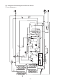
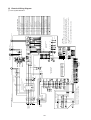
[4] Electrical Wiring Diagram
1 PUHY-(P)400·500YMF-B
–25–
TH7
TH5
21S4b
63LS
*2
LEV1
21S4a
*3
FLAG1
FLAG2
FLAG3
FLAG4
LED1
SV6
TH11
TH10c
63H1
SV1
FLAG8
FLAG7
FLAG6
FLAG5
63HS
SV4
*2
TH9b
Oil separator
TH9a
TH8
TH2
TH10b TH6
*2
MC1
TH12
63H2
MC2
63H2
MC2
TH12
PUHY-P400YMF-B
-(P)500YMF-B
SV32
SV22
❇3
PUHY-400YMF-B
SLEV
TH4
TH3
ACCUMULATOR
<Internal layout>
<LED display>
Inverter
Controller
Box
NF
TH10a
SV5b
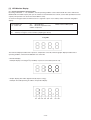
1 2 3 4 5 6 7 8 9 10
Relay output
display
(Lighting)
Display
1 2 3 4 5 6 7 8 9 10
52C1
52C2
FLAG3
21S4a
FLAG4
SV11
FLAG5
FLAG6
FLAG7 FLAG8
❇
Always
SV22/32 lighting
Display at LED lighting (blinking)
FLAG2
SV4
21S4b
SV5b
SV6
CH2,3
52F
Display the address and error code by turns.
51
1102
During
compressor run
FLAG1
Remarks
FLAG8 always
lights at
microcomputer
power ON
SV5B is closed
when FLAG3 is
turned ON.
❇Only for PUHY-P400,
(P)500YMF-B
❇ Please refer to the service handbook about other switch settings of LED display.
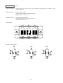
ON:1
OFF:0
( at factory shipment) Check display1
(Blinking)
ON:1
OFF:0
SW1 operation
<Operation of self-diagnosis switch (SW1)and LED display>
*1
A1
A2
SV4
SV2
14
52
C113 52C1
CH11
51C
63H
CH3
CH2
SV
5b
SV3
21
SV1 S4
Invreter
unit
PE
S
1
2 CN35
3 (3P)
6
5
4 CN34
3 (6P)
2
1
3
2 CN39
1 (3P)
6
5
4
3
2 CN33
1 (6P)
TH10b TH10a
CN12 CN09
(2P) (2P)
12 12
5
4 CN52C1
3 (5P)
2 X07
1
3
2 CNCH11
1 (3P)
CN46
(3P)
1
2
3
CN38
(3P)
1
2
3
M2
M1
Unit body
Green/
Yellow
N
TB3
Black
Blue
L3
N
PE
White
L2
Power source
L2
3N~
380/400/415V
50Hz
L3
Red
X01
SSR01
4 3
1 2
X05
X04
X03
X02
TH9
CN03
(3P)
123
1 2
CNS1
(2P)
TH4 TH3 TH6
CN06 CN05
(4P)
(2P)
12
1234
X06
Detection
circuit
Detection
circuit
A
2
ZNR01
F1
250VAC
6.3A F
1
2
CNTR
(2P)
TH5 TH8 TH7
CN02
(8P)
12345678
TH11
CN01
(2P)
12
63LS
3 2 1
LEV1
CNLV1
(5P)
12345
F3
250VAC
1A F
CNL
(3P)
1 2 3
SW3-10 are OFF for Model 200.
and ON for Model 250.
Control circuit board
(CONT board)
1
CN20
3 (3P)
T01
6
5
LEV2
CNLV2
(6P)
123456
1
CNFC1 2
(6P) 3
4
5
6
F2
600VAC
8A F
5
3
1
L3 L2 L1
L3 L2 L1
L3 L2 L1
52C1
Model 200: 24A
Model 250: 27A
6
2
4
1
3
51C1
4
2
Black
TB1
Red
VK2
VG2
VK1
VG1
WG1
WK2
L3
L2
L1
1
2 CNFC2
3 (6P)
4
5
CNW
6
(5P)
5 4 3 2 1
2
CNU 3
(5P) 4
5
CNV
(5P)
5 4 3 2 1
G K
K G
G K
K G
G K
K G
CN04
Black
Red
UK2
UG2
UK1
UG1
WK1
WG2
W
V
U
UK1
UG2
SCRM
UG1
UK2
A
NF
Noise
Filter
F1
600VAC
8A F
Black
White
Fan control board
(Fancon board) 1
White
WG2
WK2
L1
Black
White
Red
Red
WG1
WK1
L1
VG2
VK2
–26–
VG1
VK1
Controller Box
MF
U
V
W
Fan motor
CNMF
U
V MC1
W
FUSE(8A)
MAGNET CNTACTOR
TH7
63LS
LEV1
SV5b
TH9
TH8
TH5
MC1
SV4
TH6
TH11
TH4 TH10b
Inverter
contoroller
box
TH3
ACCUMULATOR
NAME
EARTH TERMINAL
POWER SOURCE TERMINAL BLOCK
SWITCH
SWITCH
RELAY
ELECTRONIC EXPANSION VALVE
ELECTRONIC EXPANSION VALVE
THERMISTER
THERMISTER
THERMISTER
THERMISTER
THERMISTER
THERMISTER
THERMISTER
THERMISTER
THERMISTER
There is not diagnostic switch in constant
capacity unit, but variable capacity unit can
diagnose it.
“*1” are not existed
Difference
TB1
SWU1,2
SW2,SW3
X01~X07
LEV2
LEV1
TH10b
TH10a
TH9
TH8
TH7
PUHN- 200·250YMF-B
63H
SV1
TH4
TH5
ALL exists
(FRONT)
LEV2
Oil
separater
TH6
21S4
TH10a
SYMBOL
TH3
PUHN-P200·250YMF-B
Appliance
<Difference of appliance>
THERMISTER
LOW SIDE PRESSURE SENSOR
HIGH PRESSURE CUT OUT SWITCH
*1 SORENOID VALVE
<Internal layout>
TH11
63LS
63H
SV2,SV3
SORENOID VALVE
SORENOID VALVE
SV1,SV4
4-WAY VALVE
21S4
SV5b
CRANK CASE HEATER(COMPRESSOR)
CORD HEATER
CH11
CH2,CH3
ELECTRIC MOTOR OF COMPRESSOR
FAN MOTOR(HEAT EXCHANGER)
MC1
OVER CURRENT RELAY
MF
51C1
52C1
FUSE(1A)
F1,F2
F3
FUSE(6.3A)
SOLID STATE RELAY
F1
SSR
NAME
VARISTOR
SYMBOL
ZNR01
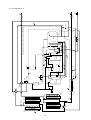
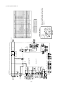
Motor (Compressor)
2 PUHN-(P)200·250YMF-B
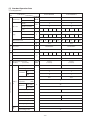
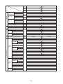
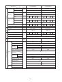
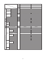
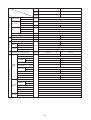
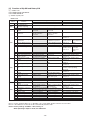
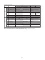
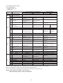
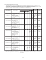
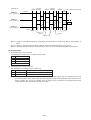
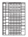
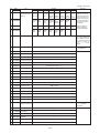
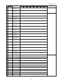
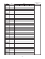
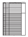
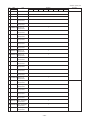
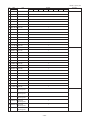
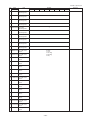
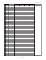
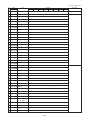
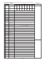
[5] Standard Operation Data
1 Cooling operation
Outdoor unit
Items
PUHY-P400YMF-B
PUHY-P500YMF-B
27.0/19.5
27.0/19.5
35.0/24.0
35.0/24.0
5
5
5
5
Indoor
DB/WB
Ambient temp.
Outdoor
Quantity
Set
Indoor unit
Condition
Quantity in operation
-
Model
125
125
Main pipe
Piping
Branch pipe
Pressure LEV opening Outdoor unit
63
32
125
125
5
m
10
10
10
10
10
10
55
-
Hi
Hi
125
32
10
10
10
Hi
Hi
55
Hi
Hi
Hi
Hi
Hi
Hi
Refrigerant volume
kg
22.4
28.9
Total current
A
28.2/26.8/25.8
35.1/33.4/32.2
Voltage
V
380 ~ 415
410
Indoor unit
410
Pulse
SC (LEV1)
kg/cm2G
(MPa)
360
340
410
410
410
179
200
344
21.5/4.4
(2.11/0.43)
21.5/4.3
(2.11/0.42)
92/102
97/102
Oil return (SLEV)
High pressure/Low pressure
(after O/S)
(before MA)
360
380 ~ 415
164
Discharge (TH11/TH12)
42
Heat exchanger outlet (TH5)
Inlet
4
5
Outlet
6
7
6/12
12/12
Accumulator
Suction (Comp) (No.1/No.2)
Sectional temperature
100
5
10
Total piping length
Indoor unit fan notch
100
Outdoor
unit
Low pressure saturation
temperature
(TH2)
Upper (TH4)
Liquid level
1
°C
30
1
Lower (TH3)
60/51
Shell bottom (Comp No.1/No.2)
SCC outlet (TH7)
27
Bypass outlet (TH8)
10
11
Bypass inlet (TH9a)
2
3
CS circuit (TH9b)
16
Circulating configuration (αOC)
Indoor
unit
65/50
0.23
LEV inlet
26
Heat exchanger outlet
12
–27–
360
280
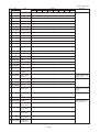
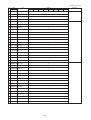
Outdoor unit
Items
Ambient temp.
Indoor
Condition
PUHY-P600YSMF-B
PUHY-P700YSMF-B
Variable
capacity unit
Constant
capacity unit
PUHY-P400YMF-B
PUHY-P500YMF-B
PUHN-P200YMF-B
PUHN-P200YMF-B
27/19.5
DB/WB
Outdoor
35/-
Quantity
Indoor unit
-
5
Set
Quantity in operation
5
-
Model
200/200/125/50/25
Main pipe
Piping
Branch pipe
5
m
5
Total piping length
Outdoor
unit
Indoor unit fan notch
30
-
Hi
Refrigerant volume
kg
28.9
35.9
Current
A
42.5/40.4/38.9
50.3/47.8/46.1
Voltage
V
380 ~ 415
LEV opening
Indoor unit
Pressure
250/200/125/100/25
Variable
capacity
SC (LEV1)
Constant
capacity
SC (LEV1)
Oil return (SLEV)
360/360/410/360/270
410/360/410/360/270
164
179
200
344
Pulse
116
Liquid pipe (LEV2)
High pressure/Low pressure
(after O/S)
(before Main ACC)
60
2
kg/cm G
(MPa)
21.5/4.6
(2.11/0.45)
Discharge (TH11/TH12)
92/102
Heat exchanger outlet (TH5)
Accumulator
Inlet
6
5
Outlet
8
7
7/13
13/13
2
1
Low pressure saturation
temperature
(TH2)
Liquid level
Upper (TH4)
30
Lower (TH3)
2
Sectional temperature
Shell bottom (Comp)
SCC outlet (TH7)
65/50
27
°C
Bypass outlet (TH8)
11
10
Bypass inlet (TH9a)
3
2
16
Circulating configuration (αOC)
0.23
Discharge temperature (TH11)
102
Liquid level
Indoor unit
1
60/51
CS circuit (TH9b)
Constant
capacity
unit
97/102
42
Suction (Comp)
Variable
capacity
unit
21.5/4.5
(2.11/0.44)
Upper (TH4)
30
4
Lower (TH3)
Shell bottom (Comp)
50
SCC outlet (TH7)
27
Bypass outlet (TH8)
13
Bypass inlet (TH9)
5
LEV inlet
26
Heat exchanger outlet
12
–28–
Outdoor unit
Items
Ambient temp.
Indoor
Condition
PUHY-P650YSMF-B
PUHY-P750YSMF-B
Variable
capacity unit
Constant
capacity unit
PUHY-P400YMF-B
PUHY-P500YMF-B
PUHN-P250YMF-B
PUHN-P250YMF-B
27/19.5
DB/WB
Outdoor
35/-
Quantity
Indoor unit
-
5
Set
Quantity in operation
5
-
Model
250/200/125/50/25
Main pipe
Piping
Branch pipe
5
m
5
Total piping length
Outdoor
unit
Indoor unit fan notch
30
-
Hi
Refrigerant volume
kg
31.9
37.9
Current
A
45.8/43.5/41.9
53.5/50.8/48.9
Voltage
V
380 ~ 415
LEV opening
Indoor unit
Pressure
250/250/125/100/25
Variable
capacity
SC (LEV1)
Constant
capacity
SC (LEV1)
Oil return (SLEV)
410/360/410/360/270
410/410/410/360/270
164
179
200
344
Pulse
116
Liquid pipe (LEV2)
High pressure/Low pressure
(after O/S)
(before Main ACC)
60
2
kg/cm G
(MPa)
21.5/4.6
(2.11/0.45)
Discharge (TH11/TH12)
92/102
Heat exchanger outlet (TH5)
Accumulator
Inlet
6
5
Outlet
8
7
7/13
13/13
2
1
Low pressure saturation
temperature (TH2)
Liquid level
Upper (TH4)
30
Lower (TH3)
2
Sectional temperature
Shell bottom (Comp)
SCC outlet (TH7)
Bypass outlet (TH8)
65/50
27
°C
CS circuit (TH9b)
11
10
3
2
16
Circulating configuration (αOC)
0.23
Discharge temperature (TH11)
102
Liquid level
Indoor unit
1
60/51
Bypass inlet (TH9a)
Constant
capacity
unit
97/102
42
Suction (Comp)
Variable
capacity
unit
21.5/4.5
(2.11/0.44)
Upper (TH4)
30
Lower (TH3)
3
Shell bottom (Comp)
50
SCC outlet (TH7)
27
Bypass outlet (TH8)
12
Bypass inlet (TH9)
4
LEV inlet
26
Heat exchanger outlet
12
–29–
Outdoor unit
Items
PUHY-400YMF-B
PUHY-500YMF-B
27.0/19.5
27.0/19.5
35.0/24.0
35.0/24.0
5
5
5
5
Indoor
DB/WB
Ambient temp.
Outdoor
Quantity
Set
Indoor unit
Condition
Quantity in operation
-
Model
125
125
Main pipe
Piping
Branch pipe
Outdoor unit
Pressure LEV opening
63
32
125
125
5
m
10
10
10
10
10
10
55
-
Hi
Hi
125
32
10
10
10
Hi
Hi
55
Hi
Hi
Hi
Hi
Hi
Hi
Refrigerant volume
kg
22.4
28.9
Total current
A
28.2/26.8/25.8
34.2/32.5/31.3
Voltage
V
380 ~ 415
430
Indoor unit
430
Pulse
SC (LEV1)
380
380 ~ 415
380
350
430
164
430
430
179
344
Oil return (SLEV)
High pressure/Low pressure
(after O/S)
(before MA)
kg/cm2G
(MPa)
20.0/4.4
(1.96/0.43)
20.0/4.3
(1.96/0.42)
90/95
95/100
Discharge (TH11/TH12)
42
Heat exchanger outlet (TH5)
Inlet
2
3
Outlet
4
5
4/10
10/10
Accumulator
Suction (Comp) (No.1/No.2)
Sectional temperature
100
5
10
Total piping length
Indoor unit fan notch
100
Outdoor
unit
Low pressure saturation
temperature
(TH2)
Upper (TH4)
3
°C
30
Liquid level
3
Lower (TH3)
Shell bottom (Comp No.1/No.2)
60/51
27
SCC outlet (TH7)
Indoor
unit
65/50
Bypass outlet (TH8)
8
9
Bypass inlet (TH9)
4
5
LEV inlet
26
Heat exchanger outlet
10
–30–
380
290
Outdoor unit
Items
Ambient temp.
Indoor
Condition
PUHY-600YSMF-B
PUHY-700YSMF-B
Variable
capacity unit
Constant
capacity unit
PUHY-400YMF-B
PUHY-500YMF-B
PUHN-200YMF-B
PUHN-200YMF-B
27/19.5
DB/WB
Outdoor
35/-
Quantity
Indoor unit
-
5
Set
Quantity in operation
5
-
Model
200/200/125/50/25
Main pipe
Piping
Branch pipe
5
m
5
Total piping length
Outdoor
unit
Indoor unit fan notch
30
-
Hi
Refrigerant volume
kg
28.9
35.9
Current
A
41.4/39.4/37.9
48.3/45.8/44.2
Voltage
V
380 ~ 415
LEV opening
Indoor unit
Pressure
250/200/125/100/25
380/380/430/380/280
Variable
capacity
SC (LEV1)
Constant
capacity
SC (LEV1)
164
Oil return (SLEV)
Pulse
116
High pressure/Low pressure
(after O/S)
(before Main ACC)
60
2
kg/cm G
(MPa)
20/4.6
(1.96/0.45)
Discharge (TH11/TH12)
Inlet
4
3
Outlet
6
5
5/11
11/11
4
3
Low pressure saturation
temperature
(TH2)
Upper (TH4)
30
Sectional temperature
Lower (TH3)
4
Shell bottom (Comp)
SCC outlet (TH7)
65/50
27
°C
Bypass outlet (TH8)
9
8
Bypass inlet (TH9)
5
4
Liquid level
Indoor unit
3
60/51
Discharge temperature (TH11)
Constant
capacity
unit
95/100
42
Suction (Comp)
Liquid level
20/4.5
(1.96/0.44)
90/95
Heat exchanger outlet (TH5)
Variable
capacity
unit
179
344
Liquid pipe (LEV2)
Accumulator
430/380/430/380/280
100
Upper (TH4)
30
Lower (TH3)
6
Shell bottom (Comp)
50
SCC outlet (TH7)
27
Bypass outlet (TH8)
11
Bypass inlet (TH9)
7
LEV inlet
26
Heat exchanger outlet
10
–31–
Outdoor unit
Items
Ambient temp.
Indoor
Condition
PUHY-650YSMF-B
PUHY-750YSMF-B
Variable
capacity unit
Constant
capacity unit
PUHY-400YMF-B
PUHY-500YMF-B
PUHN-250YMF-B
PUHN-250YMF-B
27/19.5
DB/WB
Outdoor
35/-
Quantity
Indoor unit
-
5
Set
Quantity in operation
5
-
Model
250/200/125/50/25
Main pipe
Piping
Branch pipe
5
m
5
Total piping length
Outdoor
unit
Indoor unit fan notch
30
-
Hi
Refrigerant volume
kg
31.9
37.9
Current
A
44.6/42.4/40.8
51.4/48.8/47.1
Voltage
V
380 ~ 415
LEV opening
Indoor unit
Pressure
250/250/125/100/25
430/380/430/380/280
Variable
capacity
SC (LEV1)
Constant
capacity
SC (LEV1)
164
Oil return (SLEV)
116
High pressure/Low pressure
(after O/S)
(before Main ACC)
60
2
kg/cm G
(MPa)
20/4.6
(1.96/0.45)
Discharge (TH11/TH12)
Inlet
4
3
Outlet
6
5
5/11
11/11
4
3
Low pressure saturation
temperature
(TH2)
Upper (TH4)
30
Sectional temperature
Lower (TH3)
4
Shell bottom (Comp)
SCC outlet (TH7)
65/50
27
°C
Bypass outlet (TH8)
9
8
Bypass inlet (TH9)
5
4
Liquid level
Indoor unit
3
60/51
Discharge temperature (TH11)
Constant
capacity
unit
95/100
42
Suction (Comp)
Liquid level
20/4.5
(1.96/0.44)
90/95
Heat exchanger outlet (TH5)
Variable
capacity
unit
179
344
Pulse
Liquid pipe (LEV2)
Accumulator
430/430/430/380/280
100
Upper (TH4)
30
Lower (TH3)
5
Shell bottom (Comp)
50
SCC outlet (TH7)
27
Bypass outlet (TH8)
10
Bypass inlet (TH9)
6
LEV inlet
26
Heat exchanger outlet
10
–32–
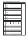
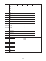
2 Heating operation
Outdoor unit
Items
PUHY-P400YMF-B
PUHY-P500YMF-B
21.0/-
21.0/-
7.0/6.0
7.0/6.0
5
5
5
5
Indoor
DB/WB
Ambient temp.
Outdoor
Quantity
Set
Indoor unit
Condition
Quantity in operation
-
Model
125
125
Main pipe
Piping
Branch pipe
Outdoor unit
Pressure LEV opening
63
32
125
125
5
m
10
10
10
10
10
10
Hi
Hi
32
10
10
Hi
Hi
55
Hi
Hi
Hi
Hi
Hi
Hi
Refrigerant volume
kg
22.4
28.7
Total current
A
26.5/25.2/24.3
32.8/31.1/30.0
Voltage
V
380 ~ 415
380 ~ 415
Indoor unit
420
SC (LEV1)
420
330
490
320
420
420
420
Oil return (SLEV)
122
High pressure/Low pressure
(after O/S)
(before MA)
kg/cm2G
(MPa)
21.5/3.6
(2.11/0.35)
21.5/3.2
(2.11/0.31)
88/93
88/93
–3
–1
Inlet
–6
–7
Outlet
–6
–7
– 5/2
– 5/0
Heat exchanger inlet (TH5)
Accumulator
Suction (Comp) (No.1/No.2)
Outdoor
unit
Low pressure saturation
temperature (TH2)
Upper (TH4)
Liquid level
– 10
°C
30
Lower (TH3)
–6
Shell bottom (Comp No.1/No.2)
43/45
CS circuit (TH9b)
40/33
5
Heat exchanger gas line
(TH10a/TH10b)
– 6/– 6
Circulating configuration (αOC)
Indoor
unit
330
0
Pulse
Discharge (TH11/TH12)
Sectional temperature
100
10
55
-
125
5
10
Total piping length
Indoor unit fan notch
100
– 7/– 7
0.28
Heat exchanger inlet
81
LEV inlet
34
–33–
320
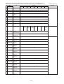
Outdoor unit
Items
Ambient temp.
Indoor
Condition
PUHY-P600YSMF-B
PUHY-P700YSMF-B
Variable
capacity unit
Constant
capacity unit
PUHY-P400YMF-B
PUHY-P500YMF-B
PUHN-P200YMF-B
PUHN-P200YMF-B
21/-
DB/WB
Outdoor
7/6
Quantity
Indoor unit
-
5
Set
Quantity in operation
5
-
Model
200/200/125/50/25
Main pipe
Piping
Branch pipe
5
m
5
Total piping length
Outdoor
unit
Indoor unit fan notch
30
-
LEV opening
Hi
Refrigerant volume
kg
28.9
35.9
Current
A
38.3/36.4/35.0
44.9/42.7/41.2
Voltage
V
Indoor unit
Pressure
250/200/125/100/25
380 ~ 415
330/330/420/430/270
Variable
capacity
SC (LEV1)
Constant
capacity
SC (LEV1)
0
Oil return (SLEV)
Pulse
122
High pressure/Low pressure
(after O/S)
(before Main ACC)
500
kg/cm2G
(MPa)
21.5/3.5
(2.11/0.34)
Discharge (TH11/TH12)
Sectional temperature
–3
–1
Inlet
–5
–6
Outlet
–5
–6
– 5/2
– 6/0
–9
– 10
Suction (Comp)
Low pressure saturation
temperature
(TH2)
Liquid level
Upper (TH4)
30
Lower (TH3)
–5
Shell bottom (Comp)
CS circuit (TH9b)
Indoor unit
–6
43/45
°C
40/33
5
Heat exchanger gas line
(TH10a/TH10b)
Constant
capacity
unit
21.5/3.5
(2.11/0.34)
88/93
Heat exchanger outlet (TH5)
Variable
capacity
unit
198
0
Liquid pipe (LEV2)
Accumulator
420/330/420/330/270
– 5/– 5
– 6/– 6
Circulating configuration (αOC)
0.28
Discharge temperature (TH11)
93
Suction (Comp)
1
Liquid level
Upper (TH4)
30
Lower (TH3)
–5
Shell bottom (Comp)
33
Heat exchanger gas line
(TH10a)
–1
Heat exchanger inlet
81
LEV inlet
34
–34–
Outdoor unit
Items
Ambient temp.
Indoor
Condition
PUHY-P650YSMF-B
PUHY-P750YSMF-B
Variable
capacity unit
Constant
capacity unit
PUHY-P400YMF-B
PUHY-P500YMF-B
PUHN-P250YMF-B
PUHN-P250YMF-B
21/-
DB/WB
Outdoor
7/6
Quantity
Indoor unit
-
5
Set
Quantity in operation
5
-
Model
250/200/125/50/25
Main pipe
Piping
Branch pipe
5
m
5
Total piping length
Outdoor
unit
Indoor unit fan notch
30
-
LEV opening
Hi
Refrigerant volume
kg
31.9
37.9
Current
A
42.0/39.9/38.5
48.3/45.9/44.2
Voltage
V
Indoor unit
Pressure
250/250/125/100/25
380 ~ 415
420/330/420/430/270
Variable
capacity
SC (LEV1)
Constant
capacity
SC (LEV1)
0
Oil return (SLEV)
Pulse
122
High pressure/Low pressure
(after O/S)
(before Main ACC)
800
kg/cm2G
(MPa)
21.5/3.5
(2.11/0.34)
Discharge (TH11/TH12)
Sectional temperature
–3
–1
Inlet
–5
–6
Outlet
–5
–6
– 5/2
– 6/0
–9
– 10
Suction (Comp)
Low pressure saturation
temperature
(TH2)
Liquid level
Upper (TH4)
30
Lower (TH3)
–5
Shell bottom (Comp)
CS circuit (TH9b)
Indoor unit
–6
43/45
°C
40/33
5
Heat exchanger gas line
(TH10a/TH10b)
Constant
capacity
unit
21.5/3.5
(2.11/0.34)
88/93
Heat exchanger outlet (TH5)
Variable
capacity
unit
198
0
Liquid pipe (LEV2)
Accumulator
420/420/420/330/270
– 5/– 5
– 6/– 6
Circulating configuration (αOC)
0.28
Discharge temperature (TH11)
93
Suction (Comp) (No.1/No.2)
0
Liquid level
Upper (TH4)
30
Lower (TH3)
–6
Shell bottom (Comp)
33
Heat exchanger gas line
(TH10a)
–2
Heat exchanger inlet
81
LEV inlet
34
–35–
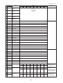
Outdoor unit
Items
PUHY-400YMF-B
PUHY-500YMF-B
21.0/-
21.0/-
7.0/6.0
7.0/6.0
5
5
5
5
Indoor
Ambient temp.
DB/WB
Outdoor
Quantity
Set
Quantity in operation
Condition
Indoor unit
-
Model
125
125
Main pipe
Piping
Branch pipe
Outdoor unit
Pressure LEV opening
63
32
125
125
5
m
10
10
-
Hi
Hi
125
10
10
32
10
10
10
10
10
Hi
Hi
10
55
Hi
Hi
Hi
Hi
Hi
Hi
Refrigerant volume
kg
22.4
28.7
Total current
A
26.0/24.7/23.8
32.2/30.6/29.5
V
380 ~ 415
380 ~ 415
Voltage
Indoor unit
420
SC (LEV1)
420
330
490
320
420
0
Pulse
Oil return (SLEV)
420
420
High pressure/Low pressure
(after O/S)
(before MA)
0
18.0/3.6
(1.77/0.35)
18.0/3.2
(1.77/0.31)
85/90
85/90
7
9
Inlet
–4
–5
Outlet
–4
–5
– 3/4
– 3/2
kg/cm2G
(MPa)
Heat exchanger inlet (TH5)
Accumulator
Suction (Comp) (No.1/No.2)
Outdoor
unit
Low pressure saturation
temperature (TH2)
–4
°C
Upper (TH4)
30
Lower (TH3)
–4
Liquid level
Indoor
unit
330
122
Discharge (TH11/TH12)
Sectional temperature
100
5
55
Total piping length
Indoor unit fan notch
100
Shell bottom (Comp No.1/No.2)
43/45
40/33
Heat exchanger gas line
(TH10a/TH10b)
– 4/– 4
– 5/– 5
Heat exchanger inlet
78
LEV inlet
37
–36–
320
Outdoor unit
Items
Ambient temp.
Indoor
Condition
PUHY-600YSMF-B
PUHY-700YSMF-B
Variable
capacity unit
Constant
capacity unit
PUHY-400YMF-B
PUHY-500YMF-B
PUHN-200YMF-B
PUHN-200YMF-B
21/-
DB/WB
Outdoor
7/6
Quantity
Indoor unit
-
5
Set
Quantity in operation
5
-
Model
200/200/125/50/25
Main pipe
Piping
Branch pipe
5
m
5
Total piping length
Outdoor
unit
Indoor unit fan notch
30
-
Hi
Refrigerant volume
kg
28.9
35.9
Current
A
37.9/36.0/34.7
44.4/42.1/40.6
Voltage
V
380 ~ 415
LEV opening
Indoor unit
Pressure
250/200/125/100/25
350/350/440/450/280
Variable
capacity
SC (LEV1)
Constant
capacity
SC (LEV1)
0
Oil return (SLEV)
Pulse
198
100
Liquid pipe (LEV2)
High pressure/Low pressure
(after O/S)
(before Main ACC)
500
2
kg/cm G
(MPa)
18/3.5
(1.76/0.34)
Discharge (TH11/TH12)
Variable
capacity
unit
Sectional temperature
7
9
Inlet
–3
–4
Outlet
–3
–4
– 3/4
– 4/2
–3
–4
Suction (Comp)
Low pressure saturation
temperature
(TH2)
Liquid level
Upper (TH4)
30
Lower (TH3)
Shell bottom (Comp)
Heat exchanger gas line
(TH10a/TH10b)
Constant
capacity
unit
Indoor unit
18/3.5
(1.76/0.34)
85/90
Heat exchanger outlet (TH5)
Accumulator
440/350/440/350/280
–3
–4
43/45
40/33
– 3/– 3
– 4/– 4
°C
Discharge temperature (TH11)
90
Suction (Comp)
3
Liquid level
Upper (TH4)
30
Lower (TH3)
–3
Shell bottom (Comp)
33
Bypass inlet (TH9)
–3
Heat exchanger gas line
(TH10a)
–3
Heat exchanger inlet
78
LEV inlet
37
–37–
Outdoor unit
Items
Ambient temp.
Indoor
Condition
PUHY-650YSMF-B
PUHY-750YSMF-B
Variable
capacity unit
Constant
capacity unit
PUHY-400YMF-B
PUHY-500YMF-B
PUHN-250YMF-B
PUHN-250YMF-B
21/-
DB/WB
Outdoor
7/6
Quantity
Indoor unit
-
5
Set
Quantity in operation
5
-
Model
250/200/125/50/25
Main pipe
Piping
Branch pipe
5
m
5
Total piping length
Outdoor
unit
Indoor unit fan notch
30
-
Hi
Refrigerant volume
kg
31.9
37.9
Current
A
41.2/39.1/37.7
47.7/45.3/43.7
Voltage
V
380 ~ 415
LEV opening
Indoor unit
Pressure
250/250/125/100/25
440/350/440/450/280
Variable
capacity
SC (LEV1)
Constant
capacity
SC (LEV1)
0
Oil return (SLEV)
Pulse
198
100
Liquid pipe (LEV2)
High pressure/Low pressure
(after O/S)
(before Main ACC)
800
2
kg/cm G
(MPa)
18/3.5
(1.76/0.34)
Discharge (TH11/TH12)
Variable
capacity
unit
Sectional temperature
7
9
Inlet
–3
–4
Outlet
–3
–4
– 3/4
– 4/2
–3
–4
Suction (Comp)
Low pressure saturation
temperature
(TH2)
Liquid level
Upper (TH4)
30
Lower (TH3)
Shell bottom (Comp)
Heat exchanger gas line
(TH10a/TH10b)
Constant
capacity
unit
Indoor unit
18/3.5
(1.76/0.34)
85/90
Heat exchanger outlet (TH5)
Accumulator
440/440/440/350/280
°C
–3
–4
43/45
40/33
– 3/– 3
– 4/– 4
Discharge temperature (TH11)
90
Suction (Comp) (No.1/No.2)
2
Liquid level
Upper (TH4)
30
Lower (TH3)
–4
Shell bottom (Comp)
33
Bypass inlet (TH9)
–4
Heat exchanger gas line
(TH10a)
–4
Heat exchanger inlet
78
LEV inlet
37
–38–
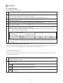
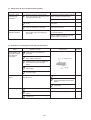
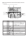
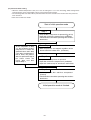
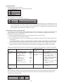
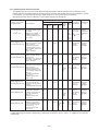
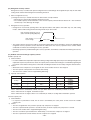
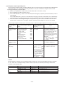
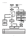
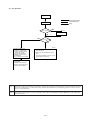
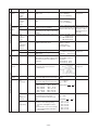
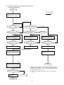
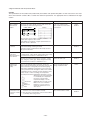
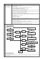
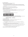
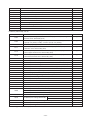
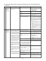
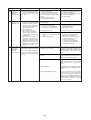
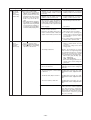
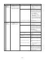
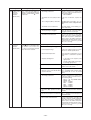
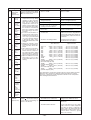
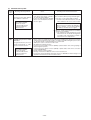
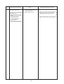
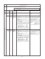
[6] Function of Dip SW and Rotary SW
(1) Outdoor unit
PUHY-P600·650·700·750YSMF-B.
PUHY-P400·500YMF-B.
1 Variable capacity unit
MAIN board
Switch
Function
SWU 1 ~ 2
1~8
SW1
9 ~ 10
1
2
3
4
SW2
5
6
7
8
9
10
1
2
3
4
SW3
5
6
7
8
9
10
1
2
3
SW4
4
5
6
7
8
9
10
Unit Address Setting
For self diagnosis/
operation monitoring
Centralized Control
Switch
Deletion of connection
information.
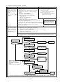
Function According to Switch Operation
When Off
When On
Set on 51 ~ 100 with the rotary switch.*2
Switch Set Timing
When Off
When On
Before power is turned on.
Refer to LED monitor display on the outdoor board.
Before power is turned on.
Centralized control
connected.
Before power is turned on.
Deletion of refrigeration
system connection
information.
Deletion of error history.
Erase IC•OC error history. During normal operation when
power is on.
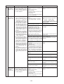
Invalid 2 hours
During normal
• Adjustment of Refriger- Ordinary control
• Refrigerant volume
operation when after compressor
ant Volume
adjustment operation.
starts.
• Ignore liquid level errors
• Ignore liquid level errors power is on.
10 minutes or
Forced defrosting
Ordinary control
Start forced defrosting.
During normal
operation when more after
compressor
power is on.
starts.
During normal operation when
Reset of the time the CS
When the CS circuit is
Timer Reset
power is on.
circuit is closed.
closed, that time is totaled.
During normal operation when
SW3-2 Function Valid/
SW3-2 Function Invalid
SW3-2 Function Valid
power is on.
Invalid
When SW3-1 is ON after power is
Indoor Unit Test Operation Stop all indoor units.
All indoor units test run
turned on.
ON.
During normal operation when
Defrosting start tempera– 8°C
– 10°C
power is on.
ture .
During normal operation when
Defrosting end tempera7°C
12°C
power is on. (Except during
ture.
defrosting)
Target low-pressure
Ordinary control
Evaporation temperature / During normal operation when
power is on.
change
2°C lower than normal
While the compressor is stopped.
Pump Down Function
Ordinary control
Pump Down Operation
Target high-pressure
Ordinary control
High pressure / 1.5 ~ 2.5 K During normal operation when
power is on.
change
higher than normal
When switching on the power.
Models
Model 400
Model 500
SW4-3 Function valid/
SW4-3 Function invalid
SW4-3 Function valid
When switching on the power.
Invalid
Change service LED
Display variable capacity
Display constant capacity During normal operation when
power is on.
unit operations.
unit operations.
When SW4-1 is ON
Configuration compensaChanges as shown below by on → off change
tion value
0 %→3 %→6 %→9 %→12 %→ – 6 %→ – 3 %→0 %
When switching on the power.
Inverter control
2-phase modulation
3-phase modulation
Switch Models
Before power is turned on.
Y Setting
Super Y Setting
Centralized control not
connected.
Storing of refrigeration
system connection
information.
Store IC•OC error history.
Note 1: Factory setting is SWU 1 to 2 = 00, SW3 - 10 = set by model. All other switches are set to OFF.
Note 2: If the address is set from 01 to 50, it automatically becomes 100.
Note 3: Factory settings are SW4-6 = OFF, setting = Y.
When operating in Super Y mode, turn SW4-6 ON.
–39–
2 Constant Capacity Unit
Switch
Function
SWU 1 ~ 2 Unit Address Setting
1
2
3
4 Ignore liquid level errors
SW2
5
6
7
Forced defrosting
8
9
10
1
2
3
6
7
8
9
Defrosting start temperature.
Defrosting end temperature.
Ignore oil-equalization
circuit irregularities
Models (Refrigerant)
10
Models (Capacity)
4
SW3
5
Function According to Switch Operation
When Off
When On
Set on 51 ~ 100 with the rotary switch.*2
Ordinary control
Ignore liquid level errors
Ordinary control
Start forced defrosting.
– 8°C
– 10°C
7°C
12°C
Ordinary control
Ignore oil-equalization
circuit irregularities
R407C Model
R22 Model
Model 200
Model 250
Switch Set Timing
When Off
When On
Before power is turned on.
During normal operation when
power is on.
During normal
Invalid 2 hours
operation when after compressor
power is on.
starts.
During normal operation when
power is on.
During normal operation when power
is on. (Except during defrosting)
During normal operation when
power is on.
Before power is turned on.
When switching on the power.
Note 1: Factory setting is SWU 1 to 2 = 00, SW3 - 10 = set by model. All other switches are set to OFF.
Note 2: If the address is set from 01 to 50, it automatically becomes 100.
–40–
PUHY-600·650·700·750 YSMF-B.
PUHY-400·500YMF-B.
1 Variable capacity unit
MAIN board
Switch
Function
SWU 1 ~ 2
1~8
SW1
9 ~ 10
1
2
SW2
3
Deletion of error history.
4
• Adjustment of Refrigerant Volume
• Ignore liquid level errors
Forced defrosting
5
6
7
8
9
10
1
2
3
4
SW3
Defrosting start temperature .
Defrosting end temperature.
8
9
10
1
2
3
4
5
6
7
8
9
10
Inverter control
Switch Models
-
6
7
Switch Set Timing
When Off
When On
Before power is turned on.
Refer to LED monitor display on the outdoor board.
Centralized control not
connected.
Storing of refrigeration
system connection
information.
Store IC•OC error history.
Ordinary control
Ordinary control
Preserve suction pressure Valid during normal
operation
SW3-2 Function Valid/
SW3-2 Function Invalid
Invalid
Indoor Unit Test Operation Stop all indoor units.
Target low-pressure
change
Target high-pressure
change
Models
Change service LED
5
SW4
Unit Address Setting
For self diagnosis/
operation monitoring
Centralized Control
Switch
Deletion of connection
information.
Function According to Switch Operation
When Off
When On
Set on 51 ~ 100 with the rotary switch.*2
0°C
7°C
Ordinary control
Ordinary control
Model 400
Display variable capacity
unit operations.
2-phase modulation
Y Setting
-
Before power is turned on.
Centralized control
connected.
Before power is turned on.
Deletion of refrigeration
system connection
information.
Erase IC•OC error history. During normal operation when
power is on.
Invalid 2 hours
During normal
• Refrigerant volume
operation when after compressor
adjustment operation.
starts.
• Ignore liquid level errors power is on.
10 minutes or
Start forced defrosting.
During normal
operation when more after
compressor
power is on.
starts.
During normal operation when
note: 3
power is on.
During normal operation when
SW3-2 Function Valid
power is on.
When SW3-1 is ON after power is
All indoor units test run
turned on.
ON.
During normal operation when
– 2°C
power is on.
During normal operation when
12°C
power is on. (Except during
defrosting)
Evaporation temperature / During normal operation when
power is on.
2°C lower than normal
High pressure / 1.5 ~ 2.5 K During normal operation when
power is on.
higher than normal
When switching on the power.
Model 500
Display constant capacity During normal operation when
power is on.
unit operations.
When SW4-1 is ON
When switching on the power.
3-phase modulation
Before power is turned on.
Super Y Setting
-
Note 1: Factory setting is SWU 1 to 2 = 00, SW3 - 10 = set by model. All other switches are set to OFF.
Note 2: If the address is set from 01 to 50, it automatically becomes 100.
Note 3: The operation cumulative time of compressor is effective to it only within 1 hour.
Note 4: Factory settings are SW4-6 = OFF, setting = Y.
When operating in Super Y mode, turn SW4-6 ON.
–41–
2 Constant Capacity Unit
Switch
Function
SWU 1 ~ 2 Unit Address Setting
1
2
3
4 Ignore liquid level errors
SW2
5
6
7
Forced defrosting
8
9
10
1
2
3
6
7
8
9
Defrosting start temperature.
Defrosting end temperature.
Ignore oil-equalization
circuit irregularities
Models (Refrigerant)
10
Models (Capacity)
4
SW3
5
Function According to Switch Operation
When Off
When On
Set on 51 ~ 100 with the rotary switch.*2
Ignore liquid level errors
Ordinary control
Ordinary control
Start forced defrosting.
0°C
– 2°C
7°C
12°C
Ordinary control
Ignore oil-equalization
circuit irregularities
R407C Model
R22 Model
Model 250
Model 200
Switch Set Timing
When Off
When On
Before power is turned on.
During normal operation when
power is on.
During normal
Invalid 2 hours
operation when after compressor
power is on.
starts.
During normal operation when
power is on.
During normal operation when power
is on. (Except during defrosting)
During normal operation when
power is on.
Before power is turned on.
When switching on the power.
Note 1: Factory setting is SWU 1 to 2 = 00, SW3 - 10 = set by model. All other switches are set to OFF.
Note 2: If the address is set from 01 to 50, it automatically becomes 100.
–42–
(2) Indoor unit
DIP SW1, 3
Switch
Switch set timing
OFF
ON
Operation by SW
OFF
ON
SW name
1
Room temp. sensor position
2
3
4
OA intake
5
Remote display select.
Fan output display Thermo. ON signal display
6
Humidifier control
At stationary heating
Always at heat.
7
Heating thermo. OFF airflow
Very low speed
Low speed
8
Heating thermo. OFF airflow
SW1-7 setting
Set airflow
9
Power failure automatic
return
Ineffective
Effective
10 Power source start/stop
Ineffective
Effective
Heat pump
Cool.only
None
Provided
SW1
1
SW3
Indoor unit inlet
Built in remote controller
Clogged filter detect.
None
Provided
Filter duration
100h
2500h
Ineffective
Effective
Model selection
Cooling capacity saving
for PKFY-P. VAM,
effective/ineffective
3
Vane
None
Provided
4
Vane swing function
None
Provided
5
Vane horizontal angle
1st setting
2nd setting
6
Vane angle set for cooling
Down blow B, C
Horizontal
–
–
Effective
Ineffective
–
Heating 4deg up
9
–
–
–
10
–
–
–
Note 1: The shaded part
table below.)
Model
Switch
SW3
At unit stopping
(at remote
controller OFF)
Louver
8
SW1
Always ineffective for PKFY-P.VAM
2
7
VBM
OFF
6
OFF
Not provided for PKFY-P.VAM
Provided for PLFY-P.VGM (ON) setting
Always down blow B,C for PKFY-P.VAM
Horizontal (ON) setting for PLFY-P.VLMD
Ineffective (ON) setting for floor
standing
indicates the setting at factory shipment. (For the SW not being shaded, refer to the
PLFY-P
3
Remarks
VLMD
PEFY-P
VKM
ON
VML
VMH
OFF
ON
PDFY-P
PFFY-P
PCFY-P
VM
VLRM, VLEM
VGM
ON
OFF
PKFY-P
VAM
ON
ON
7
OFF
3
ON
4
ON
OFF
6
OFF
ON
8
VGM
OFF
OFF
ON
OFF
OFF
ON
ON
OFF
ON
OFF
ON
OFF
OFF
ON
OFF
Note 2: The DipSW setting is only effective during unit stopping (remote controller OFF) for SW1, 2, 3 and 4 commonly
and the power source is not required to reset.)
3: When both SW1-7 and SW1-8 are being set to ON, the fan stops at the heating thermostat of OFF.
Setting of DIP SW2
Model
Capacity (model name) code
SW2 setting
P25
P32
P40
P50
P63
4
5
6
8
10
13
ON
OFF
ON
OFF
Model
Capacity (model name) code
SW2 setting
P20
ON
OFF
ON
OFF
ON
OFF
ON
OFF
ON
OFF
P71
P80
P100
P125
P140
P200
P250
14
16
20
25
28
40
50
ON
OFF
ON
OFF
–43–
ON
OFF
ON
OFF
ON
OFF
ON
OFF
Setting of DIP SW4
Setting of DIP SW5
Model
SW4
Circuit board used
1
2
3
4
PMFY-P-DBM
ON
OFF
ON
OFF
PLFY-P-VLMD
–
–
–
–
ON
OFF
ON
OFF
PDFY-P20 ~ 80VM
PLFY-P40 ~ 63VKM
OFF
OFF
OFF
ON
PLFY-P80 ~ 125VKM
ON
OFF
OFF
ON
PCFY-P-VGM
OFF
ON
OFF
ON
PKFY-P-VGM
OFF
OFF
ON
ON
Phase control
PKFY-P-VAM
PFFY-P-VLEM, P-VLRM
PEFY-P20 ~ 32VML
Relay selection
PEFY-P40 ~ 140VMH
–
–
–
–
OFF
OFF
OFF
–
ON
ON
ON
–
OFF
OFF
OFF
–
PEHY-P200·250VMH
ON
OFF
OFF
–
PDFY-P100·125VM
OFF
OFF
ON
–
Switch
Function
Operation by switch
(PLFY-P-VKM)
SWA
Ceiling height setting
220V
240V
(PCFY-P-VGM)
* The ceiling
height is
changed by
SWB setting.
3
2
1
3
2
1
3
2
1
Switch set timing
(PDFY-P-VM)
Ceiling height
3.5 m
2.8 m
2.3 m
3
2
Always after powering
1
(PLFY-P-VLMD)
SWA
For options
3
Always after powering
* As this switch is used by interlocking with SWC,
refer to the item of SWC for detail.
2
1
(PLFY-P-VKM)
SWB
1
SWA
2-way
3.5 m
3-way
3.0 m
4-way
2.7 m
2-way
SWB
Setting of air outlet opening
3-way
4-way
2
3
3.8 m
3.3 m
3.0 m
3.8 m
3.5 m
3.5 m
Always after powering
(PLFY-P-VKM, PCFY-P-VGM, PKFY-P-VGM)
* Set to the option to install the high efficiency
filter
Option
Standard
(PLFY-P-VLMD)
SWC
Airflow control
3
Always after powering
Option
2
Standard
1
SWA
SWC
(PDFY-P-VM)
3
Option
2
Standard
1
SWA
SWC
–44–
3 TEST RUN
[1] Before Test Run
(1) Check points before test run
1
Neither refrigerant leak nor loose power source/ transmission lines should be found.
2
Confirm that the resistance between the power source terminal block and the ground exceeds 2MΩ by measuring
it with a DC 500 V megger. Do not run if it is lower than 2MΩ.
Note) Never apply the megger to the MAIN board. If applied, the MAIN board will be broken.
Confirm that the Ball valve at gas and liquid, oil balance sides is being fully opened.
Note) Certainly close the cap.
Be sure that the crankcase heater has been powered by turning the main power source on at least 12 hours
before starting the test run. The shorter powering time causes compressor trouble.
If any of the power supply wires (L1, L2, L3, N, .) are mistakenly connected, it is possible to damage the unit.
Please exercise caution.
A transmission booster (RP) is required when the number of connected indoor unit models in a cooling system
exceeds the number of models specified in the chart below.
Note) The maximum number of units that can be controlled is determined by the indoor unit model, the type of
remote controller and their capabilities.
3
4
5
6
Remote controller type
(*1)
Capability of the
connected indoor units
Number of connected indoor units that
can be connected without a RP.
200 or lower
200 or higher
Remote controller PAR-F 25MA
Prior to Ver. E
After Ver. F
16 (32)
16 (32)
20 (40)
16 (32)
The number of indoor units and the total number of remote controllers is displayed within the parenthesis (
).
(*1) If even one unit that is higher than 200 exists in the cooling system, the maximum capacity will be “200 or
higher”.
* Please refer to the installation manual for more details.
* Before turning power on to the outdoor unit, first turn on the transmission booster. (If the outdoor unit are mistakenly
turned on first, turn on the transmission booster and then reset the outdoor unit power.)
(2) Caution at inverter check
Because the inverter power portion in outdoor unit electrical part box have a lot of high voltage portion, be sure to follow
the instructions shown below.
1
During energizing power source, never touch inverter power portion because high voltage (approx. 580 V) is
applied to inverter power portion.
2
When checking,
1
Shut off main power source, and check it with tester, etc.
2
Allow 10 minutes after shutting off main power source.
3
Open the MAIN board mounting panel, and check whether voltage of both ends of electrolytic capacitor is
20 V or less.
–45–
(3) Check points for test run when mounting options
Built-in optional parts
Mounting of drain
water lifting-up
mechanism
Content of test run
Check point
1
Release connector of pump circuit,
Local remote controller displays code No.
check error detection by pouring water “2503”, and the mechanism stops.
into drain pan water inlet.
No overflow from drain pan.
2
After that, connect connector of
circuit.
Drain water comes out by operations of
drain pump.
3
Check pump operations and drainage
status in cooling (test run) mode.
Sound of pump operations is heard, and
drain water comes out.
Check humidifier operations and
water supply status in heating (test
run) mode.
No water leak from connecting portions
of each water piping.
Mounting of permeable film humidifier
Result
Water is supplied to water supply tank,
and float switch is operating.
(4) Attention for mounting drain water lifting-up mechanism
Work
Disassembling and
assembling of drain
water lifting-up
mechanism
Mounting of float
switch
Electric wiring
Content of test run
Check point
1
Lead wire from control box not
damaged.
2
Rubber cap properly inserted to drain
water outlet of drain pan?
3
Insulation pipe of gas and liquid pipes
dealt with as shown in the right
figure?
4
Drain pan and piping cover mounted
without gap?
5
Drain pan hooked on cut projection of
the mechanism?
Float switch installed without contacting
with drain pan?
Insulation pipe
No gap
1
Float switch moves smoothly.
2
Float switch is mounted on mounting board straightly without deformation.
3
Float switch does not contact with
copper pipe.
1
No mistakes in wiring?
Wiring procedure is exactly followed.
2
Connectors connected surely and
tightly?
Connector portion is tightly hooked.
3
No tension on lead wire when sliding
control box?
–46–
Result
–47–
(5) Check points for system structure
In the case of the PUHY-(P) 400·500 YMF-B
Check points from installation work to test run.
Classification
Installation
and piping
Power source
wiring
Portion
Check item
Trouble
1
Instruction for selecting combination of outdoor unit, and Not operate.
indoor unit followed? (Maximum number of indoor units
which can be connected, connecting model name, and
total capacity.)
2
Follow limitation of refrigerant piping length? For example, 100 m or less (total length: 220 m) at the farthest. Not cool (at cooling).
3
Connecting piping size of branch piping correct?
4
Branch pipe properly selected?
5
Refrigerant piping diameter correct?
6
Refrigerant leak generated at connection?
Not cool, not heat, error stop.
7
Insulation work for piping properly done?
Condensation drip in piping.
8
Specified amount of refrigerant replenished?
Not cool, not heat, error stop.
9
Water leak, condensation drip in
Pitch and insulation work for drain piping properly done? drain piping.
1
Specified switch capacity and wiring diameter of main
power source used?
2
Proper grounding work done on outdoor unit?
–48–
Not heat (at heating).
Error stop, not operate.
Classification
Portion
Transmission
line
1
Limitation of transmission line length followed? For
Erroneous operation, error stop.
example, 200 m or less (total length: 500 m) at the farthest.
2
1.25 mm2 or more transmission line used?
(Remote controller 10 m or less 0.75 mm2)
Erroneous operation, error stop.
3
2-core cable used for transmission line?
Error stop in case multiple-core
cable is used.
4
Transmission line apart from power source line by 5 cm
or more?
Erroneous operation, error stop.
5
One refrigerant system per transmission line?
Not operate.
6
The short circuit connector is changed form CN41 to
Not operate.
CN40 on the MAIN board when the system is centralized
control? (Just one outdoor unit. Not all outdoor units.)
7
No connection trouble in transmission line?
Error stop or not operate.
1
Address setting properly done? (Remote controller,
indoor unit and outdoor unit.)
Error stop or not operate.
2
Setting of address No. done when shutting off power
source?
Can not be properly set with power
source turned on.
3
Address numbers not duplicated?
Not operate.
4
Turned on SW3-8 on indoor unit circuit board when
mounting room thermistor sensor?
Set temperature not obtained at heating
operations. (Thermostat stop is difficult.)
Refrigerant piping ball valve (Liquid pressure pipe, gas
pressure pipe) opened?
Turn on power source 12 hours before starting operations?
Error stop.
System set
Before starting
1
2
Check item
–49–
Trouble
Error stop, compressor trouble.
In the case of the PUHY-(P) 600·650·700·750 YSMF-B
Check points from installation work to test run.
Outdoor unit
1
6
MAIN board
1
1 68
Switch
Power
source
for
outdoor
unit
257
Switch
2
12
1 2 3 4 5
Classification
Installation
and piping
Power source
wiring
Portion
Check item
Trouble
1
Instruction for selecting combination of outdoor unit, and
indoor unit followed? (Maximum number of indoor units
which can be connected, connecting model name, and
total capacity.)
2
Follow limitation of refrigerant piping length? For example, 100 m or less (total length: 220 m) at the farthest.
3
Connecting piping size of branch piping correct?
4
Branch pipe properly selected?
5
Refrigerant piping diameter correct?
6
Refrigerant leak generated at connection?
Not cool, not heat, error stop.
7
Insulation work for piping properly done?
Condensation drip in piping.
8
Specified amount of refrigerant replenished?
Not cool, not heat, error stop.
9
Water leak, condensation drip in
Pitch and insulation work for drain piping properly done? drain piping.
1
Specified switch capacity and wiring diameter of main
power source used?
2
Proper grounding work done on outdoor unit?
Not operate.
Not cool (at cooling).
Not heat (at heating).
Error stop, not operate.
* Limitations apply when 17 or more indoor units are connected. Please refer to the installation manual.
–50–
Classification
Transmission
line
System set
Before starting
Portion
Check item
Trouble
1
Limitation of transmission line length followed? For
Erroneous operation, error stop.
example, 200 m or less (total length: 500 m) at the farthest.
2
1.25 mm2 or more transmission line used?
(Remote controller 10 m or less 0.75 mm2)
Erroneous operation, error stop.
3
2-core cable used for transmission line?
Error stop in case multiple-core
cable is used.
4
Transmission line apart from power source line by 5 cm
or more?
Erroneous operation, error stop.
5
One refrigerant system per transmission line?
Not operate.
6
The short circuit connector is changed form CN41 to
Not operate.
CN40 on the MAIN board when the system is centralized
control? (Just one outdoor unit. Not all outdoor units.)
7
No connection trouble in transmission line?
Error stop or not operate.
1
Address setting properly done? (Remote controller,
indoor unit and outdoor unit.)
Error stop or not operate.
2
Setting of address No. done when shutting off power
source?
Can not be properly set with power
source turned on.
3
Address numbers not duplicated?
Not operate.
4
Turned on SW3-8 on indoor unit circuit board when
mounting room thermistor sensor?
Set temperature not obtained at heating
operations. (Thermostat stop is difficult.)
Refrigerant piping ball valve (Liquid pressure pipe, gas
pressure pipe, oil balance pipe) opened?
Turn on power source 12 hours before starting operations?
Error stop.
1
2
–51–
Error stop, compressor trouble.
[2] Test Run Method
Operation procedure
1
Turn on universal power supply at least 12 hours before getting started → Displaying “HO” on display panel for
about two minutes
2
Press TEST RUN button twice → Displaying “TEST RUN’’ on display panel
3
Press
4
select button to change from cooling to heating operation, and vice versa → Make sure that
Press
warm or cold air is blowing out
5
Press
6
Press
7
Make sure that indoor unit fans operate normally
8
Make sure that interlocking devices such as ventilator operate normally if any
9
Press ON/OFF button to cancel test run → Stop operation
selection button → Make sure that air is blowing out
adjust button → Make sure that air blow is changed
or
button to change wind → Make sure that horizontal or downward blow is adjustable
Note) 1. If check code is displayed on remote controller or remote controller does not operate normally.
2. Test run automatically stops operating after two hours by activation of timer set to two hours.
3. During test run, test run remaining time is displayed on time display section.
4. During test run, temperature of liquid pipe in indoor unit is displayed on remote controller room temperature
display section.
5. When pressing
adjust button, depending on the model, “NOT AVAILABLE” may be displayed on remote
controller. However, it is not a malfunction.
6. When pressing
or
button, depending on the model, “NOT AVAILABLE” may be displayed on
remote controller. However, it is not a malfunction.
–52–
4 GROUPING REGISTRATION OF INDOOR UNITS WITH REMOTE CONTROLLER
(1) Switch function
•
The switch operation to register with the remote controller is shown below:
ON/OFF –
CENTRALLY CONTROLLED
1Hr.
ON
CHECK
OFF
˚C
CLOCK
FILTER
˚C
STAND BY
DEFROST
INDOOR UNIT
ADDRESS NO.
CHECK MODE
ERROR CODE
OA UNIT ADDRESS NO.
NOT AVAILABLE
TEST RUN
F Delete switch
CLOCK ON OFF
FILTER
G Registered mode
selector switch
A
CHECK
B
E Confirmation switch
TEMP.
TIMER SET
TEST RUN
NETWORK
REMOTE CONTROLLER
PAR-F25MA
D Registration switch
C Switch to assign
indoor unit address
Name
Symbol
of switch
Registration/ordinary
mode selection switch
A+B
Switch to assign indoor
unit address
C
Registration switch
D
Confirmation switch
E
Delete switch
F
Registered mode
selector switch
G
Switch to assign
interlocked unit address
H
Registration/
ordinary mode
selector switch
Name of actual switch
H Switch to assign interlocked unit address
Description
This switch selects the ordinary mode or registered mode (ordinary
mode represents that to operate indoor units).
* To select the registered mode, press the FILTER +
switch
continuously for over 2 seconds under stopping state.
Note) The registered mode can not be obtained for a while after
powering.
Pressing the FILTER +
switch displays “CENTRALLY
CONTROLLED”.
FILTER +
of TEMP
This switch assigns the unit address for “INDOOR UNIT ADDRESS
NO.”
This switch is used for group/interlocked registration.
TEST RUN
This switch is used to retrieve/identify the content of group and interlocked (connection information) registered.
CLOCK
ON
OFF
This switch is used to retrieve/identify the content of group and interlocked (connection information) registered.
This switch selects the case to register indoor units as group (group
setting mode) or that as interlocked (interlocked setting mode).
for the group setting mode
* The unit address is shown at one spot
while at two spots
for the interlocked setting mode.
of TIMER SET This switch assigns the unit address of “OA UNIT ADDRESS NO.”
–53–
(2) Attribute display of unit
• At the group registration and the confirmation/deletion of registration/connection information, the type (attribute) of the
unit is displayed with two English characters.
Display
Type (Attribute) of unit/controller
Indoor unit connectable to remote controller
Outdoor unit (PUHY-(P)400/500YMF-B)
Outdoor unit (PUHN-(P)200/250YMF-B)
Local remote controller
System controller (MJ)
[Description of registration/deletion/retrieval]
• The items of operation to be performed by the remote controller are given below. Please see the relating paragraph for
detail.
1 Group registration of indoor unit
• The group of the indoor units and operating remote controller is registered.
• It is usually used for the group operation of indoor units with different refrigerant system.
2 Retrieval/identification of group registration information of indoor units
• The address of the registered indoor units in group is retrieved (identified).
3 Retrieval/identification of registration information
• The connection information of any unit (indoor/outdoor units, remote controller or the like) is retrieved (identified).
4 Deletion of group registration information of indoor units
• The registration of the indoor units under group registration is released (deleted).
5 Deletion of the address not existing
• This operation is to be conducted when “6607” error (No ACK error) is displayed on the remote controller caused by
the miss setting at test run, or due to the old memory remained at the alteration/modification of the group composition.
Caution:
When MELANS (MJ-103MTRA for example) is being connected, do not conduct the group/pair registration using
the remote controller. The group/pair registration should be conducted by MELANS. (For detail, refer to the instruction exclusively prepared for MELANS.)
–54–
(3) Group registration of indoor unit
1) Registration method
• Group registration of indoor unit ................. 1
The indoor unit to be controlled by a remote controller is registered on the remote controller.
[Registration procedure]
1 With the remote controller under stopping or at the display of “HO”, continuously press the FILTER +
switch (A + B) at the same time for 2 seconds to change to the registration mode. (See the figure below.)
2 Assign the indoor unit address to “INDOOR UNIT ADDRESS NO.” by operating the
(Room temperature
adjustment) (C).
Then press the TEST RUN switch (D) to register. In the figure below, the “INDOOR UNIT ADDRESS NO.” is being
set to 001.
3 After completing the registration, press the FILTER +
switch (A + B) at the same time for 2 seconds to
change to the original ordinary mode (with the remote controller under stopping).
Ordinary mode
• Remote controller under stopping
• “HO” under displaying
˚C
INDOOR UNIT
ADDRESS NO
˚C
ERROR CODE
OA UNIT ADDRESS NO
INDOOR UNIT
ADDRESS NO
1
ERROR CODE
OA UNIT ADDRESS NO
1
Group setting mode
˚C
INDOOR UNIT
ADDRESS NO
ERROR CODE
OA UNIT ADDRESS NO
• Registration complete
▲
CENTRALLY CONTROLLED
ON
CHECK
˚C
FILTER
˚C
STAND BY
DEFROST
INDOOR UNIT
ADDRESS NO.
CHECK MODE
ERROR CODE
OA UNIT ADDRESS NO.
NOT AVAILABLE
ERROR CODE
OA UNIT ADDRESS NO
Indicates the type of unit
(Indoor unit in this case)
1Hr.
OFF
CLOCK
˚C
INDOOR UNIT
ADDRESS NO
ON/OFF –
2+3
TEST RUN
• Registration error
CLOCK ON OFF
▼
FILTER
CHECK
TEMP.
TIMER SET
ERROR CODE
OA UNIT ADDRESS NO
“88” flickers indicating registration error. (when the indoor unit
registered is not existing)
TEST RUN
NETWORK
REMOTE CONTROLLER
PAR-F25MA
2 Assign the
address (C)
˚C
INDOOR UNIT
ADDRESS NO
1 Change to the 3 Press the
registration
registration
mode (A + B)
switch (D)
System example
Indoor units
Group
Remote controller
–55–
• Confirm the indoor unit address No.
• Confirm the connection of the transmission line.
2)
Method of retrieval/confirmation
• Retrieval/confirmation of group registration information on indoor unit ............... 2
The address of the indoor unit being registered on the remote controller is displayed.
[Operation procedure]
1 With the remote controller under stopping or at the display of “HO”, continuously press the FILTER +
switch (A
+ B) at the same time for 2 seconds to change to the registration mode.
2 In order to confirm the indoor unit address already registered, press
switch (E). (See figure below.) When the group
of plural sets is registered, the addresses will be displayed in order at each pressing of
switch (E).
3 After completing the registration, continuously press the FILTER +
switch (A + B) at the same time for 2
seconds to change to the original ordinary mode (with the remote controller under stopping).
• Registered
▲
ON/OFF –
CENTRALLY CONTROLLED
ON
CHECK
OFF
˚C
CLOCK
INDOOR UNIT
ADDRESS NO.
1
FILTER
˚C
STAND BY
DEFROST
˚C
INDOOR UNIT
ADDRESS NO
ERROR CODE
OA UNIT ADDRESS NO
1Hr.
CHECK MODE
ERROR CODE
OA UNIT ADDRESS NO.
NOT AVAILABLE
Indicates the type of unit
(Indoor unit in this case)
TEST RUN
1
CLOCK ON OFF
FILTER
• No registration
CHECK
TIMER SET
TEST RUN
▼
TEMP.
NETWORK
REMOTE CONTROLLER
PAR-F25MA
˚C
INDOOR UNIT
ADDRESS NO
ERROR CODE
OA UNIT ADDRESS NO
Note: Only one address will be displayed
when the registration is one even the
switch is how often pressed
1 Press the switch for confirmation (E)
• Retrieval/confirmation of registration information ................. 3
The registered information on a certain unit (indoor unit, outdoor unit, remote controller or the like) is displayed.
[Operation procedure]
1 With the remote controller under stopping or at the display of “HO”, continuously press the FILTER +
switch (A
+ B) at the same time for 2 seconds to change to the registration mode.
2 Operate
switch (G) for the interlocked setting mode. (See figure below.)
3 Assign the unit address of which registration information is desired to confirm with the
(TIMER SET) switch
(H). Then press the
switch (E) to display it on the remote controller. (See figure below.)
Each pressing of
switch (E) changes the display of registered content. (See figure below.)
4 After completing the retrieval/confirmation, continuously press the FILTER +
switch (A + B) at the same time
for 2 seconds to change to the original ordinary mode (with the remote controller under stopping).
–56–
• Registered
˚C
INDOOR UNIT
ADDRESS NO
ON/OFF –
CENTRALLY CONTROLLED
ON
CHECK
˚C
CLOCK
FILTER
˚C
STAND BY
DEFROST
INDOOR UNIT
ADDRESS NO.
(Alternative
display)
1Hr.
OFF
ERROR CODE
OA UNIT ADDRESS NO
CHECK MODE
ERROR CODE
OA UNIT ADDRESS NO.
NOT AVAILABLE
TEST RUN
˚C
INDOOR UNIT
ADDRESS NO
ERROR CODE
OA UNIT ADDRESS NO
CLOCK ON OFF
FILTER
CHECK
TEMP.
TIMER SET
TEST RUN
▲
NETWORK
REMOTE CONTROLLER
PAR-F25MA
2
˚C
INDOOR UNIT
ADDRESS NO
1+2
ERROR CODE
OA UNIT ADDRESS NO
(Alternative
display)
1 Set the address
2 Press the switch for
confirmation (E)
˚C
INDOOR UNIT
ADDRESS NO
ERROR CODE
OA UNIT ADDRESS NO
˚C
INDOOR UNIT
ADDRESS NO
ERROR CODE
OA UNIT ADDRESS NO
*
• No registration
Same display will appear when
the unit of “007” is not existing.
▼
˚C
INDOOR UNIT
ADDRESS NO
3)
ERROR CODE
OA UNIT ADDRESS NO
Method of deletion
• Deletion of group registration information of indoor unit ................. 4
[Operation procedure]
1 With the remote controller under stopping or at the display of “HO”, continuously press the FILTER +
switch (A + B) at the same time for 2 seconds to change to the registration mode.
2 Press the
switch (E) to display the indoor unit address registered. (As same as 2)
3 In order to delete the registered indoor unit being displayed on the remote controller, press the
(F) switch two
times continuously. At completion of the deletion, the attribute display section will be shown as “ – – “.
(See figure below.)
Note: Completing the deletion of all indoor units registered on the remote controller returns to “HO” display.
4 After completing the registration, continuously press the FILTER +
switch (A + B) at the same time for 2
seconds to change to the original ordinary mode (with the remote controller under stopping).
CLOCK
ON
OFF
• Deletion completed
ON
CHECK
1Hr.
OFF
INDOOR UNIT
ADDRESS NO.
˚C
˚C
CLOCK
CHECK MODE
ERROR CODE
OA UNIT ADDRESS NO.
NOT AVAILABLE
INDOOR UNIT
ADDRESS NO
In case group registration with other
indoor unit is existing
FILTER
˚C
STAND BY
DEFROST
1
▲
ON/OFF –
CENTRALLY CONTROLLED
TEST RUN
ERROR CODE
OA UNIT ADDRESS NO
“– –” indicates the
deletion completed.
CLOCK ON OFF
FILTER
CHECK
1
• Deletion completed
TIMER SET
NETWORK
REMOTE CONTROLLER
PAR-F25MA
TEST RUN
In case no group
registration with other
indoor unit is existing
1 Press the switch for confirmation (F)
twice continuously
–57–
▼
ON/OFF –
TEMP.
˚C
INDOOR UNIT
ADDRESS NO
ERROR CODE
OA UNIT ADDRESS NO
4)
Deletion of information on address not existing
• Deletion of information on address not existing ................. 5
This operation is to be conducted when “6607” error (No ACK error) is displayed on the remote controller caused by
the miss setting at test run, or due to the old memory remained at the alteration/modification of group composition,
and the address not existing will be deleted.
Note : The connection information (connection between indoor unit and outdoor unit) on the refrigerant system can
not be deleted.
An example to delete the system controller of “250” from the indoor unit of “007” is shown below.
[Operation procedure]
1 With the remote controller under stopping or at the display of “HO”, continuously press the FILTER +
switch (A
+ B) at the same time for 2 seconds to change to the registration mode.
2 Operate
switch (G) for the interlocked setting mode ( ii ). (See the figure below.)
(Room temperature control) switch (C),
3 Assign the unit address existing to “OA UNIT ADDRESS No.” with the
and press
switch (E) to call the address to be deleted. (See the figure below.) As the error display on the remote
controller is usually transmitted from the indoor unit, “OA UNIT ADDRESS No.” is used as the address of the indoor unit.
4 Press the
switch (F) twice. (See the figure below.)
5 After completing the deletion, continuously press the FILTER +
switch (A + B) at the same time for 2 seconds
to return to the original ordinary mode (with the remote controller under stopping).
CLOCK
ON
OFF
• Deletion completed
When both indoor
unit and interlocked
unit addresses are
existing
˚C
INDOOR UNIT
ADDRESS NO
ERROR CODE
OA UNIT ADDRESS NO
3
˚C
INDOOR UNIT
ADDRESS NO
▲
(Alternative
display)
˚C
INDOOR UNIT
ADDRESS NO
(Alternative
display)
˚C
3
ERROR CODE
OA UNIT ADDRESS NO
ERROR CODE
OA UNIT ADDRESS NO
INDOOR UNIT
ADDRESS NO
▲
ERROR CODE
OA UNIT ADDRESS NO
1 +2
• Deletion completed
˚C
ON/OFF –
ON
CHECK
1Hr.
OFF
STAND BY
DEFROST
INDOOR UNIT
ADDRESS NO.
Deletion of
address not
existing
˚C
CLOCK
FILTER
˚C
CHECK MODE
ERROR CODE
OA UNIT ADDRESS NO.
NOT AVAILABLE
INDOOR UNIT
ADDRESS NO
TEST RUN
▼
CENTRALLY CONTROLLED
ERROR CODE
OA UNIT ADDRESS NO
(Alternative
display)
˚C
CLOCK ON OFF
INDOOR UNIT
ADDRESS NO
FILTER
CHECK
TEMP.
TIMER SET
TEST RUN
NETWORK
REMOTE CONTROLLER
PAR-F25MA
2 Press the switch for
confirmation (E)
3 Press the deletion switch (F) twice
1 Set the address (H)
–58–
ERROR CODE
OA UNIT ADDRESS NO
5 CONTROL
[1] Control of Outdoor Unit
[1]- 1 PUHY-P400·500 YMF-B
(1) Initial processing
• When turning on power source, initial processing of microcomputer is given top priority.
• During initial processing, control processing corresponding to operation signal is suspended. The control processing
is resumed after initial processing is completed. (Initial processing: Data processing in microcomputer and initial
setting of each LEV opening, requiring approx. 2 minutes at the maximum.)
(2) Control at staring
• For 3 minutes after starting, 60 Hz is the upper frequency limit. (When only No. 1 compressor is operating.)
• 75 Hz is the upper limit within 2 hours after the power supply has been turned ON and for the 30 minutes after the
compressor has started operation.
• Normal control is performed after the initial start mode (described later) has been completed.
(3)
Compressor capacity control
• Variable capacitor compressor is performed by the variable capacity compressor (No. 1: inverter motor) and
constant capacity compressor (No. 2: It has capacity control switching).
• In response to the required performance, the number of compressors operating, the switching of capacity control
and the frequency of the variable capacitor compressor is controlled so that the evaporation temperature is
between – 2 and – 6°C in cooling mode and that the condensation temperature is 49°C in heating mode.
• The fluctuation of the frequency of the variable capacitor compressor is as follows. It is performed at 2 Hz per
second.
20 to 100 Hz (TH6 > 20°C and in cooling mode, or in heating mode)
30 to 100 Hz (TH6 < 20°C and in cooling mode)
1) No. 2 compressor operation, stopping and full-load/un-load switching
1 Switching from stopping to operation of No. 2 compressor.
When the required performance cannot be obtained by only No. 1 compressor, the No. 2 compressor will be
started. (The No. 2 compressor will be started in un-load operation.)
• After the No. 1 compressor has reached 100 Hz, the No. 2 compressor stops → un-load or un-load → full-load.
2 Switching from operation to stopping of No. 2 compressor.
When the required performance is exceeded when the two compressors, No. 1 and No. 2, are operating, the No.
2 compressor is stopped or performed in un-load operation.
3 Switching from un-load to full-load of No. 2 compressor
When the required performance cannot be obtained by the No. 1 compressor and the No. 2 compressor operating in un-load, the No. 2 compressor will be switched to full-load operation.
4 Switching from full-load to un-load of No. 2 compressor
When the required performance is exceeded when the two compressors, No.1 and No. 2 operating in full-load,
the No 2 compressor will be switched to un-load operation.
2) Pressure control
The upper limit value for the high pressure (Pd) has been set for each frequency. When this value is exceeded, the
frequency is reduced every 30 seconds.
3) Discharge temperature control
The discharge temperature of the compressor (Td) is monitored during the operation. If the upper limit is exceeded, the
frequency is reduced by 5 Hz.
• Control is performed every 30 seconds after 30 seconds at the compressor starting.
–59–
• The operating temperature is 124°C (No. 1 compressor) or 115°C (No. 2 compressor).
4) Compressor frequency control
1 Ordinary control
The ordinary control is performed after the following times have passed.
• 30 seconds after the start of the compressor or 30 seconds after the completion of defrosting.
• 30 seconds after frequency control operation by the discharge temperature or the high pressure.
2 Amount of frequency fluctuation
The amount of frequency fluctuation is controlled in response to the evaporation temperature (Te) and the
condensation temperature (Tc) so that it will be approached the target values.
3 Frequency control back-up by the bypass valve
Frequency control is backed-up by the turning on (opening) the bypass valve (SV4) when only the No. 1 compressor is operated at its lowest frequency.
• Cooling
After the compressor has been operated for 15 minutes and only the No. 1 compressor is operated in un-load
(its lowest frequency), the bypass valve is turned ON when the low pressure (63 LS) is 1.0 kg/cm2 G (0.098
MPa) or less and turned OFF when it is 2.0 kg/cm2 G (0.196 MPa) or more.
ON
OFF
1.0 kg/cm2G
(0.098 MPa)
2.0 kg/cm2G
(0.196 MPa)
• Heating
After the compressor has been operated for 3 minutes and only the No. 1 compressor is operated in un-load
(its lowest frequency), the bypass valve is turned ON when the high pressure (Pd) exceeds 27 kg/cm2 (2.65
MPa) and turned OFF when it is 24 kg/cm2 (2.35 MPa) or less.
ON
OFF
24 kg/cm2G
(2.35 MPa)
27 kg/cm2G
(2.65 MPa)
(4) Bypass - capacity control
The solenoid valves have bypass valves (SV1, SV4 and SV6) that allow bypassing of the high pressure and low
pressure sides and solenoid valves (SV22 and SV32) that control the capacity control valve inside the compressor.
They operate as follows.
1) Bypass valve (SV6) [SV6 is on (open)]
• As shown in the table below, control is performed by the operation and stopping of the No. 1 compressor and No. 2
compressor.
No. 1 compressor No. 2 compressor
Stop
Stop
Operate
Stop
Operate
Operate
SV6
OFF
ON
OFF
–60–
2) Bypass solenoid valves (SV1, SV4) [Both SV1 and SV4 are on (open)]
SV4
SV1
Item
ON
OFF
ON
OFF
ON for 4 minutes
—
Compressor stopped during cooling or heating mode
ON
—
After operation has been stopped
ON for 3 minutes
—
During defrosting ((*1) in Fig below)
ON
Normally ON
ON during oil recovery operation after continuous low-frequency compressor operation.
—
At compressor is started
During oil recovery operation
When low pressure (Ps) has
dropped during lower limit frequency operation(15 minutes after start)
When the high pressure (Pd) is
risen up during lower limit frequency operation (3 minutes after
starting)
Ps < 1.0 kg/cm2G
(0.098 MPa)
—
27.5 kg/cm2G Pd 24 kg/cm2G
(2.35 MPa) and
(2.70 MPa)
after 30 seconds.
Pd
27 kg/cm2G
(2.65 MPa)
• Td >
—
130°C
(No. 1 compressor)
Td
115°C
(No. 2 compressor)
and
• Pd > 20 kg/cm2G
(1.96 MPa)
or
Ps < 3.5 kg/cm2G
(0.34 MPa)
* Example of operation of SV1
Compressor
Bypass
solenoid
valve (SV1)
Start
Thermo.
OFF
Defrost
Thermo.
ON
(4-minute)
(2-minute)
(4-minute)
Stop
(3-minute)
3) Capacity control solenoid valve (SV22, SV32).
• Operation of solenoid valve
Solenoid valve
Status
Full-load
(Operating at 100 %
capacity)
Un-load
(Capacity control
operation)
SV22
SV32
Coil
Valve
Coil
Valve
OFF
Open
OFF Closed
SV22
SV32
ON
Closed
ON
Open
COMP
• SV22 and SV32 stand for SV2 and SV3 of the No. 2
compressor.
–61–
2.0 kg/cm2G
(0.196 MPa)
Pd 24 kg/cm2G
(2.35 MPa) and after
30 seconds
ON when the high pres- Pd
sure (Pd) exceeds the
control pressure limit.
—
When the discharge temperature
(Td) is risen up
Pd
Ps
20 kg/cm2G
(1.96 MPa)
115°C
(No. 1 compressor)
100°C
(No. 2 compressor)
(5)
Oil return control (Electronic expansion valve (SLEV))
• The amount of opening of the oil-return LEV (SLEV) is determined as follows: in cooling, by the operating capacity
of the No. 1 compressor and the ambient temperature; in heating, by the operating capacity of the No. 1 compressor.
• It is opened (64) when both compressors are stopped and started for 10 minutes. (Upper limit of LEV opening is So
= 388 pulse.)
• SLEV = 0 when the No. 1 compressor is stopped.
(6) Sub-cool coil control (Electronic expansion valve (LEV1))
• The sub-cool coil control provides control every 30 seconds to keep the super heat volume from the temperature of
the inlet/outlet of the sub-cool coil (TH8, TH9) within a stable range (2 to 4 degrees).
• It controls by correcting the amount of opening according to the temperature of the inlet/outlet of the sub-cool coil
(TH5, TH7), the high pressure (Pd) and discharge temperature.
• It is closed (0) in heating or when the compressor is stopped.
• It has a fixed opening (480) in defrosting.
• During normal control, the operating range is 46 to 480.
(7) Defrosting control
1) Start of defrosting
• After there has been heating operation for 50 minutes or after 90 minutes has passed and a piping temperature
(TH5) of – 8°C or less is detected for a preset time, defrosting begins.
• When 10 minutes has passed since the compressor began operation or if 10 minutes has passed since recovery
from defrosting, setting the forced defrosting switch (Dip SW2-7) to starts forced defrosting.
2) End of defrosting
• Defrosting ends when 15 minutes have passed since the start of defrosting, or when a piping temperature (TH5) of
7°C or more is detected for 2 minutes or longer. (Note that if the defrost-prohibited time is set on 90 minutes, the
defrost-prohibit time will be 50 minutes following a 15-minute timed recovery.
• Ending the defrosting is prohibited for 2 minutes after the start of defrosting. (Note that the defrosting operation will
be ended if the piping temperature exceeds 20°C within 2 minutes of the start of defrosting.
3) Defrost-prohibit
• Defrosting is not performed for 10 minutes after the start of compressor operation and during oil recovery mode.
4) Abnormalities during defrosting
• If an error is detected during defrosting, the defrosting is stopped and the defrost-prohibit time is set to 20 minutes
by the compressor cumulative operating time.
–62–
5) Change in number of operating indoor units while defrosting
• If the number of indoor units changes while the outdoor unit is defrosting, the defrosting operation continues. Once
defrosting has ended, control for changing the number of units is performed.
• If the indoor unit is stopped while the outdoor unit is defrosting or if the thermostat is set to off, the defrosting
operation continues. Once defrosting has ended, the unit is stopped.
6) Number of compressors operating during defrosting
• The number of compressors operating during defrosting is always two.
(8) Control of liquid level detecting heater
Detect refrigerant liquid level in accumulator, and heat refrigerant with liquid level heater for judging refrigerant amount.
7 steps of duty control is applied to liquid level heater depending on frequency and outdoor air temperature, 1 minute
after starting compressor.
(9) Judgement and control of refrigerant amount
• Judge refrigerant amount by detecting refrigerant liquid surface accumulator.
1) Judgement of accumulator liquid level
• Return refrigerant from accumulator liquid level detecting circuit to compressor inlet pipe, detect piping temperature, and judge liquid level.
When heated with heater, liquid refrigerant temperature is almost equal to low pressure saturation temperature,
and gas refrigerant temperature is a little higher than low pressure saturation temperature. By comparing these
temperatures A in accumulator inlet portion, refrigerant liquid level can be judged.
Accumulator liquid level is judged in 3 steps as shown in the figure, from temperature A and liquid level detecting
temperatures (TH3, TH4). After deciding refrigerant status (Liquid: TH3 and TH4 are TH2 + 9°C or less, Gas: TH3
and TH4 are TH2 + 9°C or more), judge liquid level by comparing TH3 and TH4.
Balance pressure pipe
Dividing plate
AL=2
*Temperature A: low pressure saturation temperature
(TH2).
AL=1
AL=0
Inlet pipe
Outlet
pipe
TH2
TH4
• Judgement by the AL is at best only a
rough guideline.
Please do not add refrigerant based
on the AL reading alone.
TH3
2) Control of liquid level detection
1 Prohibition of liquid level detection
Liquid level is detected in normal conditions except for the following;
(Cooling)
• For 6 minutes after starting unit, and during unit stopping.
(Heating)
• For 6 minutes after starting unit, and during unit stopping.
• During defrosting.
• For 10 minutes after refrigerant recovery.
(Note that liquid level determination is being performed even when liquid level detection is being disregarded.)
2 In case AL = 2 is detected for 3 consecutive minutes during liquid level detection (control at excessive refrigerant
replenishment and trouble mode)
• Changed to intermittent fault check mode preceded by 3 minutes restart prevention. But it is not abnormal when
the discharge SH is high. Error stop is observed when trouble is detected again in the same intermittent fault
check mode (for 30 minutes after unit stops for intermittent fault check).
• When turning on liquid level trouble ignore switch (SW2-4), error stop is not observed, and 3 minutes restart
prevention by intermittent fault check mode is repeated. However, LED displays overflow.
(Turning SW2-4 on makes the error of TH6 < outdoor air sensor > ineffective.)
3 When operation mode shows “Stop,” excessive or insufficient refrigerant display and excessive or insufficient
refrigerant ignore display are extinguished.
–63–
(10) Refrigerant recovery control
Refrigerant recovery is conducted to prevent refrigerant from accumulating in the stopped unit (fan unit), the unit under
cooling mode and that with heating thermostat being turned off.
1) Start of refrigerant recovery
1 Refrigerant recovery is started when the two items below are fully satisfied.
• 30 minutes has passed after finishing refrigerant recovery.
• The level detector detects AL = 0 for 3 minutes continuously, or the discharge SH is high.
2) Refrigerant recovery operation
• Refrigerant is recovered by opening LEV of the objective indoor units (indoor units under stop. fan, and cooling
modes, and that with heating thermostat being turned off) for 30 seconds.
LEV opening at refrigerant recovery
(Indoor unit LEV opening 500 pulse)
LEV opening
before change
30 seconds
Starts
Finish
• The regular capacity control of the outdoor unit and the regular LEV control of the indoor unit are not applied during
refrigerant recovery operation, but are fixed with the value before the recovery operation. These controls will be
conducted one minute after finishing the recovery operation.
• Defrosting operation is prohibited during the recovery operation, and it will be conducted after finishing the recovery
operation
(11) Outdoor unit heat exchanger capacity control
1) Control method
• In order to stabilize the evaporation temperature during cooling and the high-pressure pressure during heating that
are required in response to performance needs, the capacity of the outdoor heat exchanger is controlled by regulating the fan volume of the outdoor unit by phase control and controlling the number of fans and by using the solenoid
valves.
2) Control
• When both of the compressors are stopped, the fans for the outdoor units are also stopped.
• The fans operate at full speed for 10 seconds after starting.
• The fans for the outdoor unit are stopped during defrosting.
3) Capacity control pattern
Operating mode Capacity control pattern Heat exchanger capacity No. of fans Phase control
1
50 %
1
10 to 100 %
2
100 %
2
10 to 100 %
Heating
1
100 %
2
10 to 100 %
Defrosting
1
100 %
0
0%
Cooling
Notes
21S4bON
SV5bON
21S4bOFF
SV5bOFF
21S4bON
SV5bOFF
21S4bOFF
SV5bOFF
Note 1: When there is conductivity at SV5b, it is open. When there is no conductivity at SV5b, it is closed.
Note 2: When the unit is stopped, and SV5b are open.
–64–
(12) Control at initial starting
• When the ambient temperature is low (5°C or less in cooling and – 5°C or less in heating), initial starting will be
performed if the unit is started within 4 hours of the power being turned on.
• The following initial start mode will be performed when the unit is started for the first time after the power has
been turned on.
<Flow chart of initial start mode>
Start of initial operation mode
Step 1
• Only the No.1 compressor is operated (f 75 Hz)
• Operation of the No.2 compressor is prohibited.
• Finished when cumulative operating time reaches
30 minutes.
At the completion of Step
2, if the frequency of No.1
compressor is below the
specified value and if Step
2 has been completed less
than 3 times, the process
does not proceed to Step 3
but rather enters the
Pause Step and then
repeats Step 2.
Pause Step
• Both compressors are stopped, regardless of the
demand from the indoor units. (3 minutes)
Step 2
• Only the No.1 compressor is operated.
• Operation of the No.2 compressor is prohibited.
• Operates continuously for 10 minutes and finishes.
Step 3
• Both compressors, No.1 and No.2, are operated
(Forced)
• Finished when cumulative operating time reaches
30 minutes.
Initial operation mode is finished.
–65–
<Initial start control timing chart>
3
End of initial operation mode
minutes
10 minutes 5 minutes
30 minutes
(Example 1)
ON/OFF of
No.1 compressor
Note 1
ON/OFF of
No.2 compressor
Step 1
(Example 2)
30 minutes
Step 2
Step 3
3
3
End of initial operation mode
minutes
minutes
10 minutes
10 minutes 5 minutes
Note 1
ON/OFF of
No.1 compressor
Note 2
ON/OFF of
No.2 compressor
Step 1
(Example 3)
30 minutes
Step 2
Step 2
Step 3
3
3
3
End of initial operation mode
minutes
minutes
minutes
10 minutes
10 minutes
10 minutes 5 minutes
Note 3
ON/OFF of
No.1 compressor
Note 2
ON/OFF of
No.2 compressor
Step 1
Step 2
Step 2
Step 2
Step 3
3 times
Note 1: If the frequency of No. 1 compressor is above the specified level at the end of Step 2, the mode proceeds to
Step 3.
Note 2: At the completion of Step 2, if the frequency of No. 1 compressor is below the specified value and if Step 2 has
been completed less than 3 times, the process does not proceed to Step 3 but rather enters the Pause Step
and then repeats Step 2.
Note 3: At the completion of Step 2, if it has been completed more than 3 times, the mode will proceed to Step 3 even
if the frequency of No. 1 compressor is below the specified value.
–66–
(13) Operation Mode
1) Operating modes of the indoor unit
The following five modes can be set by the remote control.
1
2
3
4
5
Cooling mode
Heating mode
Dry mode
Fan mode
Stop mode
2) Operating modes of the outdoor unit
The following are the 3 modes for the outdoor unit.
1
2
3
Cooling mode
Heating mode
Stop mode
All indoor units are operated in cooling mode
All indoor units are operated in heating mode
All indoor units are in fan or stop mode
Note : If the outdoor unit has been in the cooling mode and the other indoor units (in stop, fan, thermostat off) are set
to the heating mode, those indoor units will not be operated and the heating indicator will be flashed on the
remote controller. The reverse also applies when the outdoor unit is operated in the heating mode and the
cooling indicator will be flashed on the remote controller.
(14) Emergency response operating mode
The emergency operation mode is a mode in which the unit is run in an emergency to respond to the trouble when the
compressors (No. 1, No. 2) break down, making it possible to carry out a trouble reset using the remote control.
1) Starting the Emergency Operation Mode
1 Trouble occurs (Display the trouble code root and trouble code on the remote control).
2 Carry out trouble reset with the remote control.
3 If the trouble indicted in 1 above is of the kind that permits emergency operation (see the table below), initiate a
retry operation.
If the trouble indicated in 1 above is of the kind where emergency operation is impossible (see the table below),
restart operation after carrying out the previous trouble reset (without entering the emergency operation mode).
4 If the same trouble is detected again during the retry operation in 3 above, carry out trouble reset once more
with the remote control, then try emergency operation starting corresponding to the contents of the trouble.
Table Emergency Operation Mode Patterns and Trouble Codes for which Emergency Operation is Possible or Impossible
Emergency Mode
Pattern
Codes for which emergency operation is
possible.
When a No. 1
Serial transmission trouble
Compressor Failure VDC sensor/circuit trouble
Occurs
Breaking of overcurrent
Bus voltage trouble
Radiator panel overheat
protection
Overcurrent protection
Cooling fan trouble
Thermal sensor trouble
(Radiator panel)
IDC sensor/circuit trouble
0403
4200
4210
4220
4230
4240
4260
5110
5301
When No. 2
Overcurrent protection
Compressor Failure
Occurs
Trouble Codes for which
Emergency Operation is
Impossible
Trouble codes other than
those at left.
Action
Emergency Operation only with the
No. 2 Compressor
* After the retry operation, even if
there is a different trouble code
detected within <Inverter
Trouble> at left, press the button
and after resetting, start the unit
by emergency operation.
[Example]
4250 → Reset → Retry → 4240
→ Reset → Emergency
operation
Emergency Operation only with the
No. 1 Compressor
Caution
During emergency operation, only X marked percentage of indoor units can be operated during emergency operation.
In case, more than X marked percentage of indoor units are operated, over than the percentage of indoor units
would be on the stand-by mode.
No. 1 Compressor Failure
No. 2 Compressor Failure
×
×
400
48 %
65 %
×
×
500
65 %
65 %
–67–
[1]-2
PUHY-400·500 YMF-B
(1) Initial processing
• When turning on power source, initial processing of microcomputer is given top priority.
• During initial processing, control processing corresponding to operation signal is suspended. The control processing
is resumed after initial processing is completed. (Initial processing: Data processing in microcomputer and initial
setting of each LEV opening, requiring approx. 2 minutes at the maximum.)
(2) Control at staring
• For 3 minutes after starting, 60 Hz is the upper frequency limit. (When only No. 1 compressor is operating.)
• 75 Hz is the upper limit within 2 hours after the power supply has been turned ON and for the 30 minutes after the
compressor has started operation.
• Normal control is performed after the initial start mode (described later) has been completed.
(3)
Compressor capacity control
• Variable capacitor compressor is performed by the variable capacity compressor (No. 1: inverter motor) and
constant capacity compressor (No. 2: Model 500 has capacity control switching, Model 400 does not).
• In response to the required performance, the number of compressors operating, the switching of capacity control
and the frequency of the variable capacitor compressor is controlled so that the evaporation temperature is
between 0 and 5°C in cooling mode and that the high pressure is between 18 and 20 kg/cm2G (1.76 and 1.96
MPa) in heating mode.
• The fluctuation of the frequency of the variable capacitor compressor is as follows. It is performed at 2 Hz per
second.
20 to 100 Hz (TH6 > 20°C and in cooling mode, or in heating mode)
30 to 100 Hz (TH6 < 20°C and in cooling mode)
1) No. 2 compressor operation, stopping and full-load/un-load switching
1 Switching from stopping to operation of No. 2 compressor.
When the required performance cannot be obtained by only No. 1 compressor, the No. 2 compressor will be
started. (On Model 500, the No. 2 compressor will be started in un-load operation.)
• Model 400: After the No. 1 compressor has reached 98 Hz, the No. 2 compressor stops → starts.
• Model 500: After the No. 1 compressor has reached 100 Hz, the No. 2 compressor stops → un-load or un-load
→ full-load.
2 Switching from operation to stopping of No. 2 compressor.
When the required performance is exceeded when the two compressors, No. 1 and No. 2, are operating, the No.
2 compressor is stopped. (On Model 500, the No. 2 compressor will be performed in un-load operation.)
3 Switching from un-load to full-load of No. 2 compressor (Model 500 only)
When the required performance cannot be obtained by the No. 1 compressor and the No. 2 compressor operating in un-load, the No. 2 compressor will be switched to full-load operation.
4 Switching from full-load to un-load of No. 2 compressor (Model 500 only)
When the required performance is exceeded when the two compressors, No.1 and No. 2 operating in full-load,
the No 2 compressor will be switched to un-load operation.
2) Pressure control
The upper limit value for the high pressure (Pd) has been set for each frequency. When this value is exceeded, the
frequency is reduced every 30 seconds.
3) Discharge temperature control
The discharge temperature of the compressor (Td) is monitored during the operation. If the upper limit is exceeded, the
frequency is reduced by 5 Hz.
• Control is performed every 30 seconds after 30 seconds at the compressor starting.
–68–
• The operating temperature is 124°C.
4) Compressor frequency control
1 Ordinary control
The ordinary control is performed after the following times have passed.
• 30 seconds after the start of the compressor or 30 seconds after the completion of defrosting.
• 30 seconds after frequency control operation by the discharge temperature or the high pressure.
2 Amount of frequency fluctuation
The amount of frequency fluctuation is controlled in response to the evaporation temperature (TH2) and the high
pressure (Pd) so that it will be approached the target values.
3 Frequency control back-up by the bypass valve
Frequency control is backed-up by the turning on (opening) the bypass valve (SV4) when only the No. 1 compressor is operated at its lowest frequency.
• Cooling
After the compressor has been operated for 15 minutes and only the No. 1 compressor is operated in un-load
(its lowest frequency), the bypass valve is turned ON when the evaporation temperature (TH2) is – 30°C or
less and turned OFF when it is – 15°C or more.
ON
OFF
– 30°C
– 15°C
• Heating
After the compressor has been operated for 3 minutes and only the No. 1 compressor is operated in un-load
(its lowest frequency), the bypass valve is turned ON when the high pressure (Pd) exceeds 25 kg/cm2 (2.45
MPa) and turned OFF when it is 20 kg/cm2 (1.96 MPa) or less.
ON
OFF
20 kg/cm2G
(1.96 MPa)
25 kg/cm2G
(2.45 MPa)
(4) Bypass - capacity control
The solenoid valves have bypass valves (SV1, SV4 and SV6) that allow bypassing of the high pressure and low
pressure sides and solenoid valves (SV22 and SV32) that control the capacity control valve inside the compressor.
They operate as follows.
1) Bypass valve (SV6) [SV6 is on (open)]
• As shown in the table below, control is performed by the operation and stopping of the No. 1 compressor and No. 2
compressor.
No. 1 compressor No. 2 compressor
Stop
Stop
Operate
Stop
Operate
Operate
SV6
OFF
ON
OFF
–69–
2) Bypass solenoid valves (SV1, SV4) [Both SV1 and SV4 are on (open)]
SV4
SV1
Item
ON
OFF
ON
OFF
ON for 4 minutes
—
Compressor stopped during cooling or heating mode
ON
—
After operation has been stopped
ON for 3 minutes
—
During defrosting ((*1) in Fig below)
ON
Normally ON
ON during oil recovery operation after continuous low-frequency compressor operation.
—
At compressor is started
During oil recovery operation
When low pressure saturation
temperature (TH2) has dropped
during lower limit frequency operation(15 minutes after start)
When the high pressure (Pd) is
risen up during lower limit frequency operation (3 minutes after
starting)
—
Pd
TH2 < – 30°C
27.5 kg/cm2G Pd 24 kg/cm2G
(2.70 MPa)
(2.35 MPa) and
after 30 seconds.
—
When the discharge temperature
(Td) is risen up
—
Pd
TH2
23 kg/cm2G
(2.26 MPa)
Pd 23 kg/cm2G
(2.26 MPa) and after
30 seconds
ON when the high pres- Pd
sure (Pd) exceeds the
control pressure limit.
20 kg/cm2G
(1.96 MPa)
• Td > 130°C
and
• Pd > 20 kg/cm2G
(1.96 MPa)
or
TH2 < – 10°C
115°C
Td
* Example of operation of SV1
Compressor
Bypass
solenoid
valve (SV1)
Start
Thermo.
OFF
Defrost
Thermo.
ON
(4-minute)
(2-minute)
(4-minute)
Stop
(3-minute)
3) Capacity control solenoid valve (SV22, SV32) *Model 500 only.
• Operation of solenoid valve
Solenoid valve
Status
Full-load
(Operating at 100 %
capacity)
Un-load
(Capacity control
operation)
SV22
SV32
Coil
Valve
Coil
Valve
OFF
Open
OFF Closed
SV22
SV32
ON
Closed
ON
Open
COMP
• SV22 and SV32 stand for SV2 and SV3 of the No. 2
compressor.
–70–
– 15°C.
(5)
Oil return control (Electronic expansion valve (SLEV))
• The amount of opening of the oil-return LEV (SLEV) is determined as follows: in cooling, by the operating capacity
of the No. 1 compressor and the ambient temperature; in heating, by the operating capacity of the No. 1 compressor.
• It is opened (64) when both compressors are stopped and started for 10 minutes. (Upper limit of LEV opening is So
= 388 pulse.)
• SLEV = 0 when the No. 1 compressor is stopped.
(6) Sub-cool coil control (Electronic expansion valve (LEV1))
• The sub-cool coil control provides control every 30 seconds to keep the super heat volume from the temperature of
the inlet/outlet of the sub-cool coil (TH8, TH9) within a stable range (2 to 4 degrees).
• It controls by correcting the amount of opening according to the temperature of the inlet/outlet of the sub-cool coil
(TH5, TH7), the high pressure (Pd) and discharge temperature.
• It is closed (0) in heating or when the compressor is stopped.
• It has a fixed opening (480) in defrosting.
• During normal control, the operating range is 46 to 480.
(7) Defrosting control
1) Start of defrosting
• After there has been heating operation for 50 minutes or after 90 minutes has passed and a piping temperature
(TH5) of 0°C or less is detected for a preset time, defrosting begins.
• When 10 minutes has passed since the compressor began operation or if 10 minutes has passed since recovery
from defrosting, setting the forced defrosting switch (Dip SW2-7) to starts forced defrosting.
2) End of defrosting
• Defrosting ends when 15 minutes has passed since the start of defrosting or when the piping temperature (TH5)
becomes 7°C or more. (Note that if defrost-prohibited time has been set to 90 minutes, the defrost-prohibit time will
be 50 minutes following a 15 minute timed recovery.)
• Ending the defrosting is prohibited for 2 minutes after the start of defrosting. (Note that the defrosting operation will
be ended if the piping temperature exceeds 20°C within 2 minutes of the start of defrosting.
3) Defrost-prohibit
• Defrosting is not performed for 10 minutes after the start of compressor operation and during oil recovery mode.
4) Abnormalities during defrosting
• If an error is detected during defrosting, the defrosting is stopped and the defrost-prohibit time is set to 20 minutes
by the compressor cumulative operating time.
–71–
5) Change in number of operating indoor units while defrosting
• If the number of indoor units changes while the outdoor unit is defrosting, the defrosting operation continues. Once
defrosting has ended, control for changing the number of units is performed.
• If the indoor unit is stopped while the outdoor unit is defrosting or if the thermostat is set to off, the defrosting
operation continues. Once defrosting has ended, the unit is stopped.
6) Number of compressors operating during defrosting
• The number of compressors operating during defrosting is always two.
(8) Control of liquid level detecting heater
Detect refrigerant liquid level in accumulator, and heat refrigerant with liquid level heater for judging refrigerant amount.
7 steps of duty control is applied to liquid level heater depending on frequency and outdoor air temperature, 1 minute
after starting compressor.
(9) Judgement and control of refrigerant amount
• Judge refrigerant amount by detecting refrigerant liquid surface accumulator.
1) Judgement of accumulator liquid level
• Return refrigerant from accumulator liquid level detecting circuit to compressor inlet pipe, detect piping temperature, and judge liquid level.
When heated with heater, liquid refrigerant temperature is almost equal to low pressure saturation temperature,
and gas refrigerant temperature is a little higher than low pressure saturation temperature. By comparing these
temperature A in accumulator inlet portion, refrigerant liquid level can be judged.
Accumulator liquid level is judged in 3 steps as shown in the figure, from temperature A and liquid level detecting
temperatures (TH3, TH4). After deciding refrigerant status (Liquid: TH3 and TH4 are TH2 + 5°C or less, Gas: TH3
and TH4 are TH2 + 5°C or more), judge liquid level by comparing TH3 and TH4.
Balance pressure pipe
Dividing plate
AL=2
*Temperature A: low pressure saturation temperature
(TH2).
AL=1
AL=0
Inlet pipe
Outlet
pipe
TH2
TH4
• Judgement by the AL is at best only a
rough guideline.
Please do not add refrigerant based
on the AL reading alone.
TH3
2) Control of liquid level detection
1 Prohibition of liquid level detection
Liquid level is detected in normal conditions except for the following;
(Cooling)
• For 6 minutes after starting unit, and during unit stopping.
(Heating)
• For 6 minutes after starting unit, and during unit stopping.
• During defrosting.
• For 10 minutes after refrigerant recovery.
(Note that liquid level determination is being performed even when liquid level detection is being disregarded.)
2 In case AL = 2 is detected for 3 consecutive minutes during liquid level detection (control at excessive refrigerant
replenishment and trouble mode)
• Changed to intermittent fault check mode preceded by 3 minutes restart prevention. But it is not abnormal when
the discharge SH is high. Error stop is observed when trouble is detected again in the same intermittent fault
check mode (for 30 minutes after unit stops for intermittent fault check).
• When turning on liquid level trouble ignore switch (SW2-4), error stop is not observed, and 3 minutes restart
prevention by intermittent fault check mode is repeated. However, LED displays overflow.
(Turning SW2-4 on makes the error of TH6 < outdoor air sensor > ineffective.)
3 When operation mode shows “Stop,” excessive or insufficient refrigerant display and excessive or insufficient
refrigerant ignore display are extinguished.
–72–
(10) Refrigerant recovery control
Refrigerant recovery is conducted to prevent refrigerant from accumulating in the stopped unit (fan unit), the unit under
cooling mode and that with heating thermostat being turned off.
1) Start of refrigerant recovery
1 Refrigerant recovery is started when the two items below are fully satisfied.
• 30 minutes has passed after finishing refrigerant recovery.
• The level detector detects AL = 0 for 3 minutes continuously, or the discharge SH is high.
2) Refrigerant recovery operation
• Refrigerant is recovered by opening LEV of the objective indoor units (indoor units under stop. fan, and cooling
modes, and that with heating thermostat being turned off) for 30 seconds.
LEV opening at refrigerant recovery
(Indoor unit LEV opening 500 pulse)
LEV opening
before change
30 seconds
Starts
Finish
• The regular capacity control of the outdoor unit and the regular LEV control of the indoor unit are not applied during
refrigerant recovery operation, but are fixed with the value before the recovery operation. These controls will be
conducted one minute after finishing the recovery operation.
• Defrosting operation is prohibited during the recovery operation, and it will be conducted after finishing the recovery
operation
(11) Outdoor unit heat exchanger capacity control
1) Control method
• In order to stabilize the evaporation temperature during cooling and the high-pressure pressure during heating that
are required in response to performance needs, the capacity of the outdoor heat exchanger is controlled by regulating the fan volume of the outdoor unit by phase control and controlling the number of fans and by using the solenoid
valves.
2) Control
• When both of the compressors are stopped, the fans for the outdoor units are also stopped.
• The fans operate at full speed for 10 seconds after starting.
• The fans for the outdoor unit are stopped during defrosting.
3) Capacity control pattern
Operating mode Capacity control pattern Heat exchanger capacity No. of fans Phase control
1
50 %
1
10 to 100 %
2
100 %
2
10 to 100 %
Heating
1
100 %
2
10 to 100 %
Defrosting
1
100 %
0
0%
Cooling
Notes
21S4bON
SV5bON
21S4bOFF
SV5bOFF
21S4bON
SV5bOFF
21S4bOFF
SV5bOFF
Note 1: When there is conductivity at SV5b, it is open. When there is no conductivity at SV5b, it is closed.
Note 2: When the unit is stopped, and SV5b are open.
–73–
(12) Control at initial starting
• When the ambient temperature is low (5°C or less in cooling and – 5°C or less in heating), initial starting will be
performed if the unit is started within 4 hours of the power being turned on.
• The following initial start mode will be performed when the unit is started for the first time after the power has
been turned on.
<Flow chart of initial start mode>
Start of initial operation mode
Step 1
• Only the No.1 compressor is operated (f 75 Hz)
• Operation of the No.2 compressor is prohibited.
• Finished when cumulative operating time reaches
30 minutes.
At the completion of Step
2, if the frequency of No.1
compressor is below the
specified value and if Step
2 has been completed less
than 3 times, the process
does not proceed to Step 3
but rather enters the
Pause Step and then
repeats Step 2.
Pause Step
• Both compressors are stopped, regardless of the
demand from the indoor units. (3 minutes)
Step 2
• Only the No.1 compressor is operated.
• Operation of the No.2 compressor is prohibited.
• Operates continuously for 10 minutes and finishes.
Step 3
• Both compressors, No.1 and No.2, are operated
(Forced)
• Finished when cumulative operating time reaches
30 minutes.
Initial operation mode is finished.
–74–
<Initial start control timing chart>
3
End of initial operation mode
minutes
10 minutes 5 minutes
30 minutes
(Example 1)
ON/OFF of
No.1 compressor
Note 1
ON/OFF of
No.2 compressor
Step 1
(Example 2)
30 minutes
Step 2
Step 3
3
3
End of initial operation mode
minutes
minutes
10 minutes
10 minutes 5 minutes
Note 1
ON/OFF of
No.1 compressor
Note 2
ON/OFF of
No.2 compressor
Step 1
(Example 3)
30 minutes
Step 2
Step 2
Step 3
3
3
3
End of initial operation mode
minutes
minutes
minutes
10 minutes
10 minutes
10 minutes 5 minutes
Note 3
ON/OFF of
No.1 compressor
Note 2
ON/OFF of
No.2 compressor
Step 1
Step 2
Step 2
Step 2
Step 3
3 times
Note 1: If the frequency of No. 1 compressor is above the specified level at the end of Step 2, the mode proceeds to
Step 3.
Note 2: At the completion of Step 2, if the frequency of No. 1 compressor is below the specified value and if Step 2 has
been completed less than 3 times, the process does not proceed to Step 3 but rather enters the Pause Step
and then repeats Step 2.
Note 3: At the completion of Step 2, if it has been completed more than 3 times, the mode will proceed to Step 3 even
if the frequency of No. 1 compressor is below the specified value.
–75–
(13) Operation Mode
1) Operating modes of the indoor unit
The following five modes can be set by the remote control.
1
2
3
4
5
Cooling mode
Heating mode
Dry mode
Fan mode
Stop mode
2) Operating modes of the outdoor unit
The following are the 3 modes for the outdoor unit.
1
2
3
Cooling mode
Heating mode
Stop mode
All indoor units are operated in cooling mode
All indoor units are operated in heating mode
All indoor units are in fan or stop mode
Note: If the outdoor unit has been in the cooling mode and the other indoor units (in stop, fan, thermostat off) are set
to the heating mode, those indoor units will not be operated and the heating indicator will be flashed on the
remote controller. The reverse also applies when the outdoor unit is operated in the heating mode and the
cooling indicator will be flashed on the remote controller.
(14) Emergency response operating mode
The emergency operation mode is a mode in which the unit is run in an emergency to respond to the trouble when the
compressors (No. 1, No. 2) break down, making it possible to carry out a trouble reset using the remote control.
1) Starting the Emergency Operation Mode
1 Trouble occurs (Display the trouble code root and trouble code on the remote control).
2 Carry out trouble reset with the remote control.
3 If the trouble indicted in 1 above is of the kind that permits emergency operation (see the table below), initiate a
retry operation.
If the trouble indicated in 1 above is of the kind where emergency operation is impossible (see the table below),
restart operation after carrying out the previous trouble reset (without entering the emergency operation mode).
4 If the same trouble is detected again during the retry operation in 3 above, carry out trouble reset once more
with the remote control, then try emergency operation starting corresponding to the contents of the trouble.
Table Emergency Operation Mode Patterns and Trouble Codes for which Emergency Operation is Possible or Impossible
Emergency Mode
Pattern
Codes for which emergency operation is
possible.
When a No. 1
Serial transmission trouble
Compressor Failure VDC sensor/circuit trouble
Occurs
Breaking of overcurrent
Bus voltage trouble
Radiator panel overheat
protection
Overcurrent protection
Cooling fan trouble
Thermal sensor trouble
(Radiator panel)
IDC sensor/circuit trouble
0403
4200
4210
4220
4230
4240
4260
5110
5301
When No. 2
Overcurrent protection
Compressor Failure
Occurs
Trouble Codes for which
Emergency Operation is
Impossible
Trouble codes other than
those at left.
Action
Emergency Operation only with the
No. 2 Compressor
* After the retry operation, even if
there is a different trouble code
detected within <Inverter
Trouble> at left, press the button
and after resetting, start the unit
by emergency operation.
[Example]
4250 → Reset → Retry → 4240
→ Reset → Emergency
operation
Emergency Operation only with the
No. 1 Compressor
Caution
During emergency operation, only × marked percentage of indoor units can be operated during emergency operation.
In case, more than × marked percentage of indoor units are operated, over than the percentage of indoor units
would be on the stand-by mode.
No. 1 Compressor Failure
No. 2 Compressor Failure
×
×
400
48 %
65 %
×
×
500
65 %
65 %
–76–
[1]- 3 PUHY-P600·650·700·750 YSMF-B
(1) Initial processing
• When turning on power source, initial processing of microcomputer is given top priority.
• During initial processing, control processing corresponding to operation signal is suspended. The control processing
is resumed after initial processing is completed. (Initial processing: Data processing in microcomputer and initial
setting of each LEV opening, requiring approx. 2 minutes at the maximum.)
(2) Control at staring
• At startup, variable capacity unit operations will start first.
• For 3 minutes after starting, 60 Hz is the upper frequency limit. (When only No. 1 compressor is operating.)
• 75 Hz is the upper limit for the 30 minutes after the compressor has started operation.
• Normal control is performed after the initial start mode (described later) has been completed.
(3)
Compressor capacity control
• Compressor is performed by the variable capacity compressor on the variable capacity unit (No. 1: inverter motor)
and constant capacity compressor (No. 2: It has capacity control switching).
• In response to the required performance, the number of compressors operating, the switching of capacity control
and the frequency of the variable capacitor compressor is controlled so that the evaporation temperature is
between – 2 and – 6°C in cooling mode and that the condensation temperature is 49°C in heating mode.
• The fluctuation of the frequency of the variable capacitor compressor is as follows. It is performed at 3 Hz per
second.
20 to 100 Hz (TH6 > 20°C in cooling mode, or in heating mode)
No.3
No.1 No.2
30 to 100 Hz (TH6 < 20°C in cooling mode)
1) No. 2 compressor operation, stopping and full-load/un-load switching
Constant
capacity
unit
Variable
capacity
unit
1 Switching from stop to run of No. 2 compressor.
When the required performance cannot be obtained by only No. 1 compressor, the No. 2 compressor will be
started. (The No. 2 compressor will be started in un-load operation.)
• After the No. 1 compressor has reached 100 Hz, the No. 2 compressor stops → un-load or un-load → full-load.
2 Switching from run to stopping of No. 2 compressor.
When the required performance is exceeded when the two compressors, No. 1 and No. 2, are operating, the No.
2 compressor is stopped. (The No. 2 compressor will be performed in un-load operation.)
3 Switching from un-load to full-load of No. 2 compressor.
When the required performance cannot be obtained by the No. 1 compressor and the No. 2 compressor operating in un-load, the No. 2 compressor will be switched to full-load operation.
4 Switching from full-load to un-load of No. 2 compressor.
When the required performance is exceeded when the two compressors, No.1 and No. 2 operating in full-load,
the No 2 compressor will be switched to un-load operation.
2) No. 3 compressor operation/stopping.
1 Switching No. 3 compressor from stopping to operation
When the required performance cannot be obtained with only the No. 1 and No. 2 variable capacity unit compressors, the constant capacity unit No. 3 compressor will be started.
*The No. 3 compressor is equipped with a capacity control switching function. It starts with un-load operation
in the initial start mode and during defrosting, and starts in full-load operation at all other times.
–77–
2
Switching No. 3 compressor from operation to stopping
When the required performance is exceeded with the No. 1 and No. 2 variable capacity unit compressors and the
constant capacity unit No. 3 compressor in operation, the No. 3 compressor will be stopped.
3) Pressure control
• The upper limit value for the high pressure (Pd) has been set for each frequency. When this value is exceeded, the
frequency is reduced every 30 seconds.
• While the constant capacity unit is in operation, if the high pressure (63HS) value exceeds 26 kg/cm2G (2.55 MPa),
the constant capacity unit compressor will be stopped.
4) Discharge temperature control
1 The discharge temperature of the compressor (Variable capacity unit: TH11, TH12, Constant capacity unit:
TH11) is monitored during the operation. If the upper limit is exceeded, the frequency is reduced by 5 Hz.
• Control is performed every 30 seconds after 30 seconds at the compressor starting.
• The operating temperature is 124°C (No.1 compressor) or 115°C (No. 2, 3 compressor).
2 While the constant capacity unit is in operation, if the constant capacity unit discharge temperature (TH11)
exceeds 115°C, the constant capacity unit compressor will be stopped.
5) Compressor frequency control
1 Ordinary control
The ordinary control is performed after the following times have passed.
• 30 seconds after the start of the compressor or 30 seconds after the completion of defrosting.
• 30 seconds after frequency control operation by the discharge temperature or the high pressure.
2 Amount of frequency fluctuation
The amount of frequency fluctuation is controlled in response to the evaporation temperature (Te) and the
condensation temperature (Tc) so that it will be approached the target values.
3 Frequency control back-up by the bypass valve
Frequency control is backed-up by the turning on (opening) the bypass valve (SV4) when only the No. 1 compressor is operated at its lowest frequency.
• Cooling
After the compressor has been operated for 15 minutes and only the No. 1 compressor is operated in un-load
(its lowest frequency), the bypass valve is turned ON when the low pressure (63LS) is 1.0 kg/cm2G (0.098 MPa)
or less and turned OFF when it is 2.0 kg/cm2G (0.196 MPa) or more.
ON
OFF
1.0 kg/cm2G
(0.098 MPa)
2.0 kg/cm2G
(0.196 MPa)
• Heating
After the compressor has been operated for 3 minutes and only the No. 1 compressor is operated in un-load (its
lowest frequency), the bypass valve is turned ON when the high pressure (Pd) exceeds 27 kg/cm2 (2.65 MPa)
and turned OFF when it is 24 kg/cm2 (2.35 MPa) or less.
ON
OFF
24 kg/cm2G
27 kg/cm2G
(2.35 MPa)
(2.65 MPa)
–78–
(4) Bypass - capacity control
The solenoid valves have bypass valves (SV1, SV4 and SV6) that allow bypassing of the high pressure and low
pressure sides and solenoid valves (SV22 and SV32) that control the capacity valve inside the compressor. Those
operation are as follows.
SV1
SV4
: Installed × : Not Installed
SV6
SV22, SV32
Variable Capacity Unit
×
Constant Capacity Unit
Use
Maintenance of high-pressure/low-pressure,
discharge temperature
Controls the
compressors’
internal volume
control valve.
* The compressor of constant capacity unit starts in un-load operation in the initial start mode and during defrosting
only, and starts in full-load operation at all other times by SV22,23 switching.
Normally compressor capacity control is not performed.
1) Bypass Valve (SV6) (SV6 is open when ON, variable capacity unit only)
• The valve is set as follows according to whether the variable capacity unit No. 1 and No. 2 compressors are
operating.
No. 1 Compressor No. 2 Compressor
Stopped
Stopped
Operating
Stopped
Operating
Operating
SV6
OFF
ON
OFF
–79–
2) Bypass solenoid valves (SV1, SV4) [Both SV1 and SV4 are on (open)]
<Variable capacity unit>
SV1
SV4
Item
ON
At compressor is started
OFF
ON
OFF
ON for 4 minutes
—
Compressor stopped during cooling or heating mode
ON
—
After operation has been stopped
ON for 3 minutes
—
During defrosting ((*1) in Fig below)
ON
Normally ON
ON during oil recovery operation after
continuous low-frequency compressor
operation.
—
During oil recovery operation
When low pressure (Ps) has
dropped during lower limit frequency operation(15 minutes after start)
Ps < 1.0 kg/cm2G
(0.098 MPa)
—
27.5 kg/cm2G Pd 24 kg/cm2G
(2.35 MPa) and
(2.70 MPa)
after 30 seconds.
Pd
When the high pressure (Pd) is
risen up during lower limit frequency operation (3 minutes after
starting)
When the discharge temperature
(Td) is risen up
Pd
27 kg/cm2G
(2.65 MPa)
(4-minute)
Thermo.
OFF
Thermo.
ON
(2-minute)
Pd 24 kg/cm2G
(2.35 MPa) and
after 30 seconds
—
20 kg/cm2G
(1.96 MPa)
115°C
(No. 1 compressor)
100°C
(No. 2 compressor)
—
130°C
(No. 1 compressor)
• Td >
Td
115°C
(No. 2 compressor)
and
• Pd > 20 kg/cm2G
(1.96 MPa)
or
Ps < 3.5 kg/cm2G
(0.34 MPa)
Compressor
Start
2.0 kg/cm2G
(0.196 MPa)
ON when the high Pd
pressure (Pd) exceeds the control
pressure limit.
* Example of operation of SV1
Bypass
solenoid
valve (SV1)
Ps
Defrost
(4-minute)
–80–
Stop
(3-minute)
<Constant Capacity Unit>
SV1
SV4
Item
ON
OFF
ON
OFF
At compressor is started
ON for 4 minutes
—
After thermostat reset or 3
minutes after startup
ON for 4 minutes
—
Compressor stopped during
cooling or heating mode
ON for 3 minutes
—
After operation has been stopped
ON for 3 minutes
—
ON during normal operation
—
During defrosting ((*1) in Fig
below)
Low pressure
(63LS) < 1.0 kg/cm2G
(0.098 MPa)
When low pressure (63LS) has
dropped
Pd 24 kg/cm2G
27.5 kg/cm2G
(2.35 MPa) and
(2.70 MPa)
after 30 seconds
Pd
When the high pressure (Pd) is
risen up
When the discharge temperature
(Td) is risen up.
Low pressure
(63LS) 1.5 kg/cm2G
(0.147 MPa)
When the discharge
temperature > 110°C
and high pressure
(Pd) > 20 kg/cm2G
(1.96 MPa) or low
pressure (63LS) <
2.5 kg/cm2G
(0.245 MPa).
When the high pressure (Pd) is
fallen up.
When the discharge temperature 105°C
—
—
—
—
—
—
—
In heating mode, at starting
and low volume of indoor
unit, if high pressure (Pd) <
12 kg/cm2G (1.18 MPa)
and low pressure (Ps) <
1.0 kg/cm2G (0.098 MPa)
When the high
pressure (Pd)
13 kg/cm2G
(1.27 MPa) and after
30 minutes of
operation.
* Example of SV1 operation
Compressor
Bypass
solenoid
valve (SV1)
Start
Thermo.
OFF
(4-minute)
Defrost
(*1)
Thermo.
ON
(3-minute) (4-minute)
(4-minute)
Stop
(3-minute)
3) Capacity control solenoid valve (SV22, SV32)
• Operation of solenoid valve
Solenoid valve
Status
Full-load
(Operating at 100 %
capacity)
Un-load
(Capacity control
operation)
SV22
SV32
Coil
Valve
Coil
Valve
OFF
Open
OFF Closed
SV22
SV32
ON
Closed
ON
Open
COMP
• SV22 and SV32 stand for SV2 and SV3 of the No. 2, No. 3
compressor.
–81–
(5)
Oil return control (Electronic expansion valve (SLEV); Variable Capacity Unit only)
• The amount of opening of the oil-return LEV (SLEV) is determined as follows: in cooling, by the operating capacity
of the No. 1 compressor and the ambient temperature; in heating, by the operating capacity of the No. 1 compressor.
• It is opened (64) when both compressors are stopped and started for 10 minutes. (Upper limit of LEV opening is So
= 388 pulse.)
• SLEV = 0 when the No. 1 compressor is stopped.
(6) Sub-cool coil control (Electronic expansion valve (LEV1))
• The sub-cool coil control provides control every 30 seconds to keep the super heat volume from the temperature of
the inlet/outlet of the sub-cool coil (TH8, TH9) within a stable range (2 to 4 degrees).
• It controls by correcting the amount of opening according to the temperature of the inlet/outlet of the sub-cool coil
(TH5, TH7), the high pressure (Pd) and discharge temperature.
• It is closed (0) in heating or when the compressor is stopped.
• It has a fixed opening (480) in defrosting.
• During normal control, the operating range is 46 to 480 (Variable capacity unit), 46 to 300 (Constant capacity unit).
(7) Defrosting control
Defrosting operation controls vary depending on the state of operations before defrosting begins.
State of operations
before defrosting
Defrosting
operation control
Defrost 1 - 1
Defrost 1 - 2
Defrost 2
Variable capacity unit
Operating
Operating
Operating
Constant capacity unit
Operating
Stopped
Stopped
Variable capacity unit
Defrost
Defrost
Defrost
Constant capacity unit
Defrost
Defrost *1
Stopped *2
Indoor unit LEV
Full open
Full closed
*1 When the cumulative operating time of the constant capacity unit compressor 30 minutes.
*2 When the cumulative operating time of the constant capacity unit compressor < 30 minutes.
1) Start of defrosting
1 Defrost 1 - 1, 2
• After there has been heating operation for 50 minutes and a piping temperature (TH5) of – 8°C or less is detected
for a preset time in either the variable or constant capacity units, defrosting starts.
2 Defrost 2
• After there has been heating operation for 50 minutes, and a piping temperature of (TH5) of – 8°C or less is
detected for a preset time in the variable capacity unit, defrosting starts.
3 Forced Defrosting
• When 10 minutes has passed since the compressor began operation, or if 10 minutes has passed since recovery
from defrosting, setting the forced defrosting switch (DIPSW2-7) to ON starts forced defrosting.
2) End of Defrosting
1 Defrost 1 - 1, 2
• Defrosting ends when 15 minutes have passed since the start of defrosting, or when a piping temperature (TH5)
of 7°C or more is detected for 2 minutes or longer in both the variable and constant capacity units.
2 Defrost 2
• Defrosting ends when 15 minutes have passed since the start of defrosting, or when a piping temperature (TH5)
of 8°C or more is detected for 2 minutes or longer in the variable capacity unit.
* Ending the defrosting is prohibited for 2 minutes after the start of defrosting. (Note that the defrosting operation will
be stopped if the piping temperature exceeds 20°C or if the high pressure (Pd) exceeds 20 kg/cm2G (1.96 MPa).)
3) Defrost-prohibit
• Defrosting is not performed for 10 minutes after the start of compressor operation and during oil recovery mode.
4) Abnormalities during defrosting
• If an error is detected during defrosting, the defrosting is stopped and the defrost-prohibit time is set to 20 minutes
by the compressor cumulative operating time.
–82–
5) Change in number of operating indoor units while defrosting
• If the number of indoor units changes while the outdoor unit is defrosting, the defrosting operation continues. Once
defrosting has ended, control for changing the number of units is performed.
• If the indoor unit is stopped while the outdoor unit is defrosting or if the thermostat is set to off, the defrosting
operation continues. Once defrosting has ended, the unit is stopped.
6) Number of compressors operating during defrosting
• The number of compressors operating during defrosting is three in defrost 1 - 1 or 2, two in defrost 2.
(8) Control of liquid level detecting heater
Detect refrigerant liquid level in accumulator, and heat refrigerant with liquid level heater for judging refrigerant amount.
7 steps of duty control is applied to liquid level heater depending on frequency and outdoor air temperature, 1 minute
after starting compressor.
(9) Judgement and control of refrigerant amount
• Judge refrigerant amount by detecting refrigerant liquid surface accumulator.
1) Judgement of accumulator liquid level
• Return refrigerant from accumulator liquid level detecting circuit to compressor inlet pipe, detect piping temperature, and judge liquid level.
When heated with heater, liquid refrigerant temperature is almost equal to low pressure saturation temperature,
and gas refrigerant temperature is a little higher than low pressure saturation temperature. By comparing these
temperatures A in accumulator inlet portion, refrigerant liquid level can be judged.
Accumulator liquid level is judged in 3 steps as shown in the figure, from temperature A and liquid level detecting
temperatures (TH3, TH4). After deciding refrigerant status (Liquid: TH3 and TH4 are TH2 + 9°C or less, Gas: TH3
and TH4 are TH2 + 9°C or more), judge liquid level by comparing TH3 and TH4.
Balance pressure pipe
Dividing plate
AL=2
*Temperature A: low pressure saturation temperature.
Variable capacity unit; TH2
Constant capacity unit; Saturation
temperature
of 63LS
AL=1
AL=0
Inlet pipe
Outlet
pipe
TH2
TH4
• Judgement by the AL is at best only a
rough guideline.
Please do not add refrigerant based
on the AL reading alone.
TH3
2) Control of liquid level detection
1 Prohibition of liquid level detection
Liquid level is detected in normal conditions except for the following;
(Cooling)
• For 6 minutes after starting unit, and during unit stopping.
(Heating)
• For 6 minutes after starting unit, and during unit stopping.
• During defrosting.
• For 10 minutes after refrigerant recovery.
(Note that liquid level determination is being performed even when liquid level detection is being disregarded.)
2 In case AL = 2 is detected for 3 consecutive minutes during liquid level detection (control at excessive refrigerant
replenishment and trouble mode)
• Changed to intermittent fault check mode preceded by 3 minutes restart prevention. But it is not abnormal when
the discharge SH is high. Error stop is observed when trouble is detected again in the same intermittent fault
check mode (for 30 minutes after unit stops for intermittent fault check).
• When turning on liquid level trouble ignore switch (SW2-4), error stop is not observed, and 3 minutes restart
prevention by intermittent fault check mode is repeated. However, LED displays overflow.
(Turning SW2-4 on makes the error of TH6 < outdoor air sensor > ineffective.)
3 When operation mode shows “Stop,” excessive or insufficient refrigerant display and excessive or insufficient
refrigerant ignore display are extinguished.
–83–
(10) Liquid Distribution Control (electronic expansion valve (LEV2) constant capacity unit only)
• Liquid distribution control refers to the process by which liquid refrigerant returning from the constant and variable
capacity units during heating is equally distributed, and the opening of the constant capacity unit LEV2 is adjusted
so that there is no deficiency of liquid refrigerant in the accumulator of each unit.
1 Distribution occurs during heating operations when both the variable and constant capacity units are in operation.
When the constant capacity unit is stopped, the LEV2 opening = 60.
2 The LEV2 opening is set to a standard which varies depending on the current operation frequency.
3 The levels of the superheating level (SH1) of the variable capacity unit temperature A and TH10 (whichever
temperature is higher) and the accumulator liquid level (AL1) are compared to the superheating level (SH2) of the
constant capacity unit temperature A and TH10a and the accumulator liquid level (AL2) to correct the standard
opening of the LEV2 in 2 above.
* Temperature A: low pressure saturation temperature.
Chart: Corrections to the Standard LEV2 Opening
Constant Capacity Unit
Superheating Level
SH2 > 7
SH2
Variable
SH1 > 7
Capacity Unit
SH1
60
7
Accumulator Level
AL = 0 or 1
AL = 0 or 1
no change
AL = 2
AL = 2
opening up
AL = 2
7
AL = 2
opening down
no change
AL = 0 or 1
AL = 0 or 1
opening up
no change
opening down
no change
opening down
no change
opening up
no change
200
2000
Standard LEV2 Opening
Range of Corrections to LEV2 Opening
* Even when the constant capacity unit is stopped, the after-mentioned liquid refrigerant correction control operation may
control LEV2 operations. After the power source has been turned on, and before the variable capacity unit compressor
begins operation, the LEV2 is opened to 200. (After compressor operation begins, LEV2 = 60)
–84–
(11) Liquid Refrigerant Correction Control
The liquid refrigerant correction control adjusts the liquid refrigerant amounts between both accumulators in the
unlikely event that the liquid refrigerant amount in both the constant and variable capacity unit accumulators should
be insufficient, or if and excessive amount of liquid refrigerant is returned from either accumulator.
During this operation, Service LED No. 4 on the variable capacity unit will light up.
Direction of Accumulator Liquid Transfer
Variable Capacity Unit
Constant Capacity Unit
↓
Indoor Unit
Actuator Action
Constant Capacity Unit
Start Conditions
• In heating mode
• Run and stop indoor units
are mixed.
• Pd 13k (1.27 MPa), or
during an accumulator
overflow preliminary error.
• Td < 110°C
Compressor
LEV2
SV5b
–
–
–
Variable
Indoor
capacity
Unit
Other
unit
Stopping
Conditions
Operation:
normal
control
While all
indoor units
are operating
Td 115°C
• Verify
surplus
refrigerant
• LD1 lights
up
–
–
LED Monitor
No.4
Stop:
LEV = 60
Variable Capacity Unit
↓
Constant Capacity Unit
• In heating mode
• While the constant capacity
unit is stopped.
• During an accumulator
overflow preliminary error
in the variable capacity unit
(AL1 = 2)
• TdSH < 40 deg *1
OFF
2000
ON
(open)
–
–
–
• AL1 = 0 or 1
• Continuing
for 20
minutes
Liquid
refrigerant
control 2
LD3 lights
up
Variable Capacity Unit
↓
Constant Capacity Unit
• In heating mode
OFF
• During constant capacity
unit operation
• When AL1 = 2 is detected in
the variable capacity unit.
• TdSH < 40 deg *1
2000
ON
(open)
–
–
–
• AL1 = 0 or 1
• AL2 = 2
• Continuing
for 10
minutes
Liquid
refrigerant
control 4
LD5 lights
up
Variable Capacity Unit
↓
Constant Capacity Unit
• In cooling mode
• While the constant capacity
unit is stopped.
• During an accumulator
overflow preliminary error
in the variable capacity unit
(AL1 = 2)
• Constant capacity unit
AL2 = 0 or 1
• Variable capacity unit
TH6 < 25°C
OFF
2000
ON
(open)
Fan
ON
Operation
frequency
level
up
All
• AL1 = 0 or 1
indoor
• Continuing
unit
for 15
LEV = 60 minutes
Liquid
refrigerant
control 6
LD7 lights
up
Variable Capacity Unit
↓
Constant Capacity Unit
• In heating mode
• Constant capacity unit
switches from operation to
stopping.
• Constant capacity unit AL2 = 0
OFF
2000
ON
(open)
–
–
–
• AL1 = 0 or 1
• Continuing
for 3 ~ 6
minutes
Liquid
refrigerant
control 7
LD8 lights
up
Constant Capacity Unit
↓
Variable Capacity Unit
• In heating mode
• During an accumulator
overflow error delay in the
constant capacity unit
(AL2 = 2)
• Variable capacity unit
AL1 = 0 or 1
–
–
–
–
Operation
frequency
level
down
–
• AL2 = 0 or 1
• AL1 = 2
• Continuing
for 10
minutes
Liquid
refrigerant
control 3
LD4 lights
up
Constant Capacity Unit
↓
Variable Capacity Unit
• During cooling or heating
• During an accumulator
overflow preliminary error
in the constant capacity
unit (AL2 = 2)
• Variable capacity unit
AL1 = 0 or 1
OFF
2000
• AL1 = 2
ON LEV1 = 21S4a, All
b
indoor
• Continuing
(open) 480
SV4 ON ON
unit
for 4
21S4
LEV = 60 minutes
OFF
Liquid
refrigerant
control 5
LD6 lights
up
* 1 TdSH (Discharge temperature superheating) = Discharge temperature (TH11 or TH12) - Tc (High pressure saturation
temperature)
–85–
(12) Refrigerant recovery control
Refrigerant recovery is conducted to prevent refrigerant from accumulating in the stopped unit (fan unit), the unit under
cooling mode and that with heating thermostat being turned off.
1) Start of refrigerant recovery
1 Refrigerant recovery is started when the two items below are fully satisfied.
• 30 minutes has passed after finishing refrigerant recovery.
• The variable capacity unit level detector or the constant capacity unit level detector detects AL = 0 for 3 minutes
continuously, or the discharge SH is high.
2) Refrigerant recovery operation
• Refrigerant is recovered by opening LEV of the objective indoor units (indoor units under stop. fan, and cooling
modes, and that with heating thermostat being turned off) for 30 seconds.
LEV opening at refrigerant recovery
(Indoor unit LEV opening 500 pulse)
LEV opening
before change
30 seconds
Starts
Finish
• The regular capacity control of the outdoor unit and the regular LEV control of the indoor unit are not applied during
refrigerant recovery operation, but are fixed with the value before the recovery operation. These controls will be
conducted one minute after finishing the recovery operation.
• Defrosting operation is prohibited during the recovery operation, and it will be conducted after finishing the recovery
operation.
(13) Outdoor unit heat exchanger capacity control
Variable capacity unit
1) Control method
• In order to stabilize the evaporation temperature during cooling and the high-pressure pressure during heating that are
required in response to performance needs, the capacity of the outdoor heat exchanger is controlled by regulating the
fan volume of the outdoor unit by phase control and controlling the number of fans and by using the solenoid valves.
2) Control
• When both of the compressors are stopped, the fans for the outdoor units are also stopped.
• The fans operate at full speed for 10 seconds after starting.
• The fans for the outdoor unit are stopped during defrosting.
3) Capacity control pattern
Operating mode Capacity control pattern Heat exchanger capacity No. of fans Phase control
1
50 %
1
10 to 100 %
2
100 %
2
10 to 100 %
Heating
1
100 %
2
10 to 100 %
Defrosting
1
100 %
0
0%
Cooling
Notes
21S4bON
SV5bON
21S4bOFF
SV5bOFF
21S4bON
SV5bOFF
21S4bOFF
SV5bOFF
Note 1: When there is conductivity at SV5b, it is open. When there is no conductivity at SV5b, it is closed.
Note 2: When the unit is stopped, and SV5b are open.
Note 3: When the unit is stopped, there is no conductivity at 21S4b, in cooling mode and SV5b is opened.
Constant capacity unit
1) Control Method
• In response to performance needs, the fan level is controlled by the same phase control used in the variable
capacity unit.
2) Control
• The fan is stopped when the (constant capacity unit) compressor is stopped.
• The fan is operated at full speed for 5 seconds after the (constant capacity unit) compressor is started.
• The fan for the outdoor unit is stopped during defrosting.
• The fan is sometimes operated when the TH10a drops, even when the compressor is stopped.
• The fan is operated for several minutes after the compressor is stopped.
–86–
(14) Control at initial starting
• When the ambient temperature is low (5°C or less in cooling and – 5°C or less in heating), initial starting will not
be performed even if the unit is started within 4 hours of the power being turned on.
• The following initial start mode will be performed when the unit is started for the first time after the power has
been turned on.
• When operation volume is low in the indoor unit, the constant
Start of initial operation mode
capacity unit may not run for as long as 7 hours. In order to
finish initial operation mode quickly, increase the operation
volume of the indoor unit and run under high-external temperature conditions.
<Flow chart of initial start mode>
• No.1 compressor: variable capacity unit No.1 compressor
• No.2 compressor: variable capacity unit No.2 compressor
• No.3 compressor: constant capacity unit compressor
Step 1
•Only the No.1 compressor is operated (f 75 Hz)
•Operation of the No.2 and No.3 compressor is
prohibited to operate.
•Finished when cumulative operating time reaches
30 minutes.
Pause Step
At the completion of “Step 2”,
if the frequency of No.1
compressor is below the
specified value and if “Step 2”
has been completed less
than 3 times, the process
does not proceed to Step 3
but rather enters the “Pause
Step” and then repeats “Step 2”.
• Both compressors are stopped, regardless of the
demand from the indoor units. (3 minutes)
Step 2
• Only the No.1 compressor is operated.
• Operation of the No.2 and No.3 compressor are
prohibited to operate.
• Finished when the cumulative operating time
reaches 10 minutes.
Step 3
• Compressors No.1 and No.2 are both operated.
(forced)
• Operation of the No.3 compressor is prohibited to
operate.
• Finished when cumulative operating time reaches
5 minutes.
Step 4
• Compressor No.1 is operated alone, or No.1 and
No.2 compressors are both operated.
(equal to load)
• Operation of the No.3 compressor is prohibited to
operate.
• Finished when the length of continued operation
reaches a set amount of time.
Step 5
If 7 hours has passed since
the power was turned on,
step 4, 5, and 6 are skipped.
• Compressor No.1 and No.2 are both operated.
(forced)
• Operation of the No.3 compressor is prohibited to
operate.
• Finished when the length of continued operation
reaches 5 minutes of time.
Step 6
• Compressor No.1 and No.3 are both operated.
(forced)
• Operation of the No.2 compressor is prohibited to
operate.
• Finished when the length of continued operation
reaches 10 minutes of time.
End initial operation mode.
–87–
<Initial Start Control Timingchart>
For steps 1 - 3
3
End of initial operation mode
minutes
10 minutes 5 minutes
(Example 1)
30 minutes
ON/OFF of
No.1 compressor
Note 1
ON/OFF of
No.2 compressor
Step 1
(Example 2)
30 minutes
Step 2
Step 3
3
3
End of initial operation mode
minutes
minutes
10 minutes
10 minutes 5 minutes
Note 1
ON/OFF of
No.1 compressor
Note 2
ON/OFF of
No.2 compressor
Step 1
(Example 3)
30 minutes
Step 2
Step 2
Step 3
3
3
3
End of initial operation mode
minutes
minutes
minutes
10 minutes
10 minutes
10 minutes 5 minutes
Note 3
ON/OFF of
No.1 compressor
Note 2
ON/OFF of
No.2 compressor
Step 1
Step 2
Step 2
Step 2
Step 3
3 times
Note 1: If the frequency of No. 1 compressor is above the specified level at the end of Step 2, the mode proceeds to
Step 3.
Note 2: At the completion of Step 2, if the frequency of No. 1 compressor is below the specified value and if Step 2 has
been completed less than 3 times, the process does not proceed to Step 3 but rather enters the Pause Step
and then repeats Step 2.
Note 3: At the completion of Step 2, if it has been completed more than 3 times, the mode will proceed to Step 3 even
if the frequency of No. 1 compressor is below the specified value.
–88–
For steps 4 - 6
(Example 1)
ON/OFF of
No.1 compressor
5
minutes
End of initial operation mode
10
minutes
A-minute
(A-minute Definitions)
Conditions
Operation
Frequency Level (Hz)
A
–
0
minute
10
minutes
Constant capacity unit
power on 7 hours.
ON/OFF of
No.2 compressor
63LS
4.2 K
217 (For variable capacity
unit model 500)
183 (For variable capacity
unit model 400)
63LS
3.8 K
100
63LS
1.5 K
100
ON/OFF of
No.3 compressor
Step 4
Step 5 Step 6
Note 4
Other
(Example 2)
ON/OFF of
No.1 compressor
5
minutes
Less than
A-minute
Less than
A-minute
End of initial operation mode
10
minutes
A-minute
Note 1
ON/OFF of
No.2 compressor
ON/OFF of
No.3 compressor
Step 4
(Example 3)
ON/OFF of
No.1 compressor
Less than 100
Step 5
Less than
5 minutes
Less than
5 minutes
Step 6
5
minutes
Note 4
End of initial operation mode
10
minutes
A-minute
ON/OFF of
No.2 compressor
Note 2
ON/OFF of
No.3 compressor
Note 4
Step 4
Step 5
Step 6
Step 5
Step 4
Step 4
Step 5
–89–
25
minutes
50
minutes
7 hr
(Example 4)
ON/OFF of
No.1 compressor
5
Less than
minutes 10 minutes
5
Less than
minutes 10 minutes
5
minutes
A-minute
End of initial operation mode
10
minutes
ON/OFF of
No.2 compressor
Note 3
ON/OFF of
No.3 compressor
Step 4
Step 6 Note 4
Step 5
Step 6
Note 4
Step 5
Step 4
Step 5
Step 4
Step 6
Note 4
Note 1: If Step 4 is interrupted (compressor stopped by thermostat OFF or regular stop), Step 4 will be redone at
restart.
Note 2: If Step 5 is interrupted, Step 5 will be redone at restart after performing Step 4 several times.
Note 3: If Step 6 is interrupted, Step 5 and Step 6 will be redone at restart after performing Step 4 several times.
Note 4: During Step 6, the No. 3 compressor runs with Un-load operation.
(15) Operation Mode
1) Operating modes of the indoor unit
The following five modes can be set by the remote control.
1
2
3
4
5
Cooling mode
Heating mode
Dry mode
Fan mode
Stop mode
2) Operating modes of the outdoor unit
The following are the 3 modes for the outdoor unit.
1
2
3
Cooling mode
Heating mode
Stop mode
All indoor units are operated in cooling mode
All indoor units are operated in heating mode
All indoor units are in fan or stop mode
Note: If the outdoor unit has been in the cooling mode and the other indoor units (in stop, fan, thermostat off) are set
to the heating mode, those indoor units will not be operated and the heating indicator will be flashed on the
remote controller. The reverse also applies when the outdoor unit is operated in the heating mode and the
cooling indicator will be flashed on the remote controller.
–90–
(17) Emergency response operating mode
The emergency operation mode is a mode in which the unit is run in an emergency to respond to the trouble when the
compressors (No. 1, No. 2) break down, making it possible to carry out a trouble reset using the remote control.
1) Starting the Emergency Operation Mode
1 Trouble occurs (Display the trouble code root and trouble code on the remote control).
2 Carry out trouble reset with the remote control.
3 If the trouble indicted in 1 above is of the kind that permits emergency operation (see the table below), initiate a
retry operation.
If the trouble indicated in 1 above is of the kind where emergency operation is impossible (see the table below),
restart operation after carrying out the previous trouble reset (without entering the emergency operation mode).
4 If the same trouble is detected again during the retry operation in 3 above, carry out trouble reset once more
with the remote control, then try emergency operation starting corresponding to the contents of the trouble.
Table Emergency Operation Mode Patterns and Trouble Codes for which Emergency Operation is Possible or Impossible
Emergency Mode
Pattern
Codes for which emergency operation is
possible.
When a No. 1
Serial transmission trouble
Compressor Failure VDC sensor/circuit trouble
Occurs
Breaking of overcurrent
Bus voltage trouble
Radiator panel overheat
protection
Overcurrent protection
Cooling fan trouble
Thermal sensor trouble
(Radiator panel)
IDC sensor/circuit trouble
0403
4200
4210
4220
Trouble Codes for which
Emergency Operation is
Impossible
Trouble codes other than
those at left.
4230
4240
4260
5110
5301
When No. 2
Overcurrent protection
Compressor Failure
Occurs
Constant capacity
unit
Error (stop)
Action
Emergency Operation with the
No. 2 and No. 3 Compressor
* After the retry operation, even if
there is a different trouble code
detected within <Inverter
Trouble> at left, press the button
and after resetting, start the unit
by emergency operation.
[Example]
4250 → Reset → Retry → 4240
→ Reset → Emergency
operation
Emergency Operation with the
No. 1 and No. 3 Compressor
Emergency response operation
(a)High pressure/ lowwith the variable capacity unit only
pressure pressure
error
1302 (No. 1 and No. 2 compressor).
(b)Reverse phase error
4103
(c)Communication error
No communication with
variable capacity unit
(d)Constant capacity unit
power-off and LEV2
open
(e)Oil equalization circuit
irregularity
1559
Error codes other than those at right.
Caution
During emergency operation, only × marked percentage of indoor units can be operated during emergency operation.
In case, more than × marked percentage of indoor units are operated, over than the percentage of indoor units
would be on the stand-by mode.
Failed Compressor
No.1
No.2
No. 3
External temp. (TH6)
TH6 20°C (cooling) or heating
TH6 < 20°C (cooling)
TH6 20°C (cooling) or heating
TH6 < 20°C (cooling)
Don’t care
Model 600 ~ 750
× 60 ~ 70 %
× 45 ~ 55 %
× 65 ~ 75 %
× 45 ~ 55 %
× 80 ~ 90 %
–91–
Notes
No.2 + No.3 Compressors on
No.2 Compressor only
No.1 + No.3 Compressors on
No.1 Compressor only
No.1 + No.2 Compressors on
2) Terminating Emergency Response Operation Mode
(Termination Conditions)
When one of the following conditions is met, emergency operation mode is terminated.
1 Cumulative compressor operation time in the cooling mode exceeds 4 hours.
2 Cumulative compressor operation time in the heating mode exceeds 2 hours.
3 Emergency operation mode trouble detected.
(Control During and After Termination)
• During and after termination, the compressor will be stopped and a repeat error code will be flashed on the
remote controller.
• If there is a repeat trouble reset during termination, retry operations will start by repeating steps 1 to 4 in 1).
–92–
[1]-4
PUHY-600·650·700·750 YSMF-B
(1) Initial processing
• When turning on power source, initial processing of microcomputer is given top priority.
• During initial processing, control processing corresponding to operation signal is suspended. The control processing
is resumed after initial processing is completed. (Initial processing: Data processing in microcomputer and initial
setting of each LEV opening, requiring approx. 2 minutes at the maximum.)
(2) Control at staring
• At startup, variable capacity unit operations will start first.
• For 3 minutes after starting, 60 Hz is the upper frequency limit. (When only No. 1 compressor is operating.)
• 75 Hz is the upper limit for the 30 minutes after the compressor has started operation.
• Normal control is performed after the initial start mode (described later) has been completed.
(3)
Compressor capacity control
• Compressor is performed by the variable capacity compressor on the variable capacity unit (No. 1: inverter motor)
and constant capacity compressor (No. 2: Model 500 has capacity control switching, Model 400 does not).
• In response to the required performance, the number of compressors operating, the switching of capacity control
and the frequency of the variable capacitor compressor is controlled so that the evaporation temperature is
between 0 and 5°C in cooling mode and that the high pressure is between 18 and 20 kg/cm2G (1.76 and 1.96
MPa) in heating mode.
• The fluctuation of the frequency of the variable capacitor compressor is as follows. It is performed at 3 Hz per
second.
20 to 100 Hz (TH6 > 20°C in cooling mode, or in heating mode)
No.3
No.1 No.2
30 to 100 Hz (TH6 < 20°C in cooling mode)
1) No. 2 compressor operation, stopping and full-load/un-load switching
Constant
capacity
unit
Variable
capacity
unit
1 Switching from stop to run of No. 2 compressor.
When the required performance cannot be obtained by only No. 1 compressor, the No. 2 compressor will be
started. (On Model 500, the No. 2 compressor will be started in un-load operation.)
• Model 400: After the No. 1 compressor has reached 98 Hz, the No. 2 compressor stops → starts.
• Model 500: After the No. 1 compressor has reached 100 Hz, the No. 2 compressor stops → un-load or un-load
→ full-load.
2 Switching from run to stopping of No. 2 compressor.
When the required performance is exceeded when the two compressors, No. 1 and No. 2, are operating, the No.
2 compressor is stopped. (On Model 500, the No. 2 compressor will be performed in un-load operation.)
3 Switching from un-load to full-load of No. 2 compressor (Model 500 only)
When the required performance cannot be obtained by the No. 1 compressor and the No. 2 compressor operating in un-load, the No. 2 compressor will be switched to full-load operation.
4 Switching from full-load to un-load of No. 2 compressor (Model 500 only)
When the required performance is exceeded when the two compressors, No.1 and No. 2 operating in full-load,
the No 2 compressor will be switched to un-load operation.
2) No. 3 compressor operation/stopping.
1 Switching No. 3 compressor from stopping to operation
When the required performance cannot be obtained with only the No. 1 and No. 2 variable capacity unit compressors, the constant capacity unit No. 3 compressor will be started.
–93–
2 Switching No. 3 compressor from operation to stopping
When the required performance is exceeded with the No. 1 and No. 2 variable capacity unit compressors and the
constant capacity unit No. 3 compressor in operation, the No. 3 compressor will be stopped.
3) Pressure control
• The upper limit value for the high pressure (Pd) has been set for each frequency. When this value is exceeded, the
frequency is reduced every 30 seconds.
• While the constant capacity unit is in operation, if the high pressure (63HS) value exceeds 25 kg/cm2G (2.45 MPa),
the constant capacity unit compressor will be stopped.
4) Discharge temperature control
1 The discharge temperature of the compressor (Variable capacity unit: TH11, TH12, Constant capacity unit:
TH11) is monitored during the operation. If the upper limit is exceeded, the frequency is reduced by 5 Hz.
• Control is performed every 30 seconds after 30 seconds at the compressor starting.
• The operating temperature is 124°C.
2 While the constant capacity unit is in operation, if the constant capacity unit discharge temperature (TH11)
exceeds 130°C, the constant capacity unit compressor will be stopped.
5) Compressor frequency control
1 Ordinary control
The ordinary control is performed after the following times have passed.
• 30 seconds after the start of the compressor or 30 seconds after the completion of defrosting.
• 30 seconds after frequency control operation by the discharge temperature or the high pressure.
2 Amount of frequency fluctuation
The amount of frequency fluctuation is controlled in response to the evaporation temperature (TH2) and the high
pressure (Pd) so that it will be approached the target values.
3 Frequency control back-up by the bypass valve
Frequency control is backed-up by the turning on (opening) the bypass valve (SV4) when only the No. 1 compressor is operated at its lowest frequency.
• Cooling
After the compressor has been operated for 15 minutes and only the No. 1 compressor is operated in un-load
(its lowest frequency), the bypass valve is turned ON when the evaporation temperature (TH2) is – 30°C or
less and turned OFF when it is – 15°C or more.
ON
OFF
– 30°C
– 15°C
• Heating
After the compressor has been operated for 3 minutes and only the No. 1 compressor is operated in un-load
(its lowest frequency), the bypass valve is turned ON when the high pressure (Pd) exceeds 25 kg/cm2 (2.45
MPa) and turned OFF when it is 20 kg/cm2 (1.96 MPa) or less.
ON
OFF
20 kg/cm2G
(1.96 MPa)
25 kg/cm2G
(2.45 MPa)
–94–
(4) Bypass - capacity control
The solenoid valves have bypass valves (SV1, SV4 and SV6) that allow bypassing of the high pressure and low
pressure sides and solenoid valves (SV22 and SV32) that control the capacity valve inside the compressor. Those
operation are as follows.
SV1
SV4
: Installed × : Not Installed
SV6
SV22, SV32
Variable Capacity Unit
×
Constant Capacity Unit
Use
Maintenance of high-pressure/low-pressure,
discharge temperature
×
Controls the
compressors’
internal volume
control valve.
1) Bypass Valve (SV6) (SV6 is open when ON, variable capacity unit only)
• The valve is set as follows according to whether the variable capacity unit No. 1 and No. 2 compressors are
operating.
No. 1 Compressor No. 2 Compressor
Stopped
Stopped
Operating
Stopped
Operating
Operating
SV6
OFF
ON
OFF
–95–
2) Bypass solenoid valves (SV1, SV4) [Both SV1 and SV4 are on (open)]
<Variable capacity unit>
SV1
SV4
Item
ON
At compressor is started
OFF
ON
OFF
ON for 4 minutes
—
Compressor stopped during cooling or heating mode
ON
—
After operation has been stopped
ON for 3 minutes
—
During defrosting ((*1) in Fig below)
ON
Normally ON
ON during oil recovery operation after continuous low-frequency compressor operation.
—
During oil recovery operation
When low pressure saturation
temperature (TH2) has dropped
during lower limit frequency operation(15 minutes after start)
—
27.5 kg/cm2G
(2.70 MPa)
Pd
When the high pressure (Pd) is
risen up during lower limit frequency operation (3 minutes after
starting)
When the discharge temperature
(Td) is risen up
TH2 < – 30°C
Pd 24 kg/cm2G
(2.35 MPa) and
after 30 seconds.
Pd
23 kg/cm2G
(2.26 MPa)
(4-minute)
Thermo.
OFF
Thermo.
ON
(2-minute)
Pd 23 kg/cm2G
(2.26 MPa) and
after 30 seconds
ON when the high
pressure (Pd) ex- Pd
ceeds the control
pressure limit.
20 kg/cm2G
(1.96 MPa)
—
• Td > 130°C
and
• Pd > 20 kg/cm2G
(1.96 MPa)
or
TH2 < – 10°C
115°C
Compressor
Start
– 15°C
—
* Example of operation of SV1
Bypass
solenoid
valve (SV1)
TH2
Defrost
(4-minute)
–96–
Stop
(3-minute)
Td
<Constant Capacity Unit>
SV1
SV4
Item
ON
OFF
ON
OFF
At compressor is started
ON for 4 minutes
—
After thermostat reset or 3
minutes after startup
ON for 4 minutes
—
Compressor stopped during
cooling or heating mode
ON for 3 minutes
—
After operation has been stopped
ON for 3 minutes
—
ON during normal operation
—
During defrosting ((*1) in Fig
below)
Low pressure
Low pressure
(63LS) < 1.0 kg/cm2G (63LS) 1.5 kg/cm2G
(0.098 MPa)
(0.147 MPa)
When low pressure (63LS) has
dropped
Pd 23 kg/cm2G
26.5 kg/cm2G
(2.25 MPa) and
(2.55 MPa)
after 30 seconds
Pd
When the high pressure (Pd) is
risen up
When the discharge temperature
(Td) is risen up.
When the discharge
temperature > 130°C
and high pressure
(Pd) > 20 kg/cm2G
(1.96 MPa) or low
pressure (63LS) <
2.5 kg/cm2G
(0.245 MPa).
When the high pressure (Pd) is
fallen up.
When the discharge temperature 115°C
—
—
—
—
—
—
—
In heating mode, at starting
and low volume of indoor
unit, if high pressure (Pd) <
12 kg/cm2G (1.18 MPa) and
low pressure saturation
temperature (ET) < – 20°C
When the high
pressure (Pd)
13 kg/cm2G
(1.27 MPa) and
after 30 minutes of
operation.
* Example of SV1 operation
Compressor
Bypass
solenoid
valve (SV1)
Start
Thermo.
OFF
(4-minute)
Defrost
(*1)
Thermo.
ON
(3-minute) (4-minute)
(4-minute)
Stop
(3-minute)
3) Capacity control solenoid valve (SV22, SV32) *Model 500 only.
• Operation of solenoid valve
Solenoid valve
Status
Full-load
(Operating at 100 %
capacity)
Un-load
(Capacity control
operation)
SV22
SV32
Coil
Valve
Coil
Valve
OFF
Open
OFF Closed
SV22
SV32
ON
Closed
ON
Open
COMP
• SV22 and SV32 stand for SV2 and SV3 of the No. 2
compressor.
–97–
(5)
Oil return control (Electronic expansion valve (SLEV); Variable Capacity Unit only)
• The amount of opening of the oil-return LEV (SLEV) is determined as follows: in cooling, by the operating capacity
of the No. 1 compressor and the ambient temperature; in heating, by the operating capacity of the No. 1 compressor.
• It is opened (64) when both compressors are stopped and started for 10 minutes. (Upper limit of LEV opening is So
= 388 pulse.)
• SLEV = 0 when the No. 1 compressor is stopped.
(6) Sub-cool coil control (Electronic expansion valve (LEV1))
• The sub-cool coil control provides control every 30 seconds to keep the super heat volume from the temperature of
the inlet/outlet of the sub-cool coil (TH8, TH9) within a stable range (2 to 4 degrees).
• It controls by correcting the amount of opening according to the temperature of the inlet/outlet of the sub-cool coil
(TH5, TH7), the high pressure (Pd) and discharge temperature.
• It is closed (0) in heating or when the compressor is stopped.
• It has a fixed opening (480) in defrosting.
• During normal control, the operating range is 46 to 480 (Variable capacity unit), 46 to 300 (Constant capacity unit).
(7) Defrosting control
Defrosting operation controls vary depending on the state of operations before defrosting begins.
State of operations
before defrosting
Defrosting
operation control
Defrost 1 - 1
Defrost 1 - 2
Defrost 2
Variable capacity unit
Operating
Operating
Operating
Constant capacity unit
Operating
Stopped
Stopped
Variable capacity unit
Defrost
Defrost
Defrost
Constant capacity unit
Defrost
Defrost *1
Stopped *2
Indoor unit LEV
Full open
Full closed
*1 When the cumulative operating time of the constant capacity unit compressor 30 minutes.
*2 When the cumulative operating time of the constant capacity unit compressor < 30 minutes.
1) Start of defrosting
1 Defrost 1 - 1, 2
• After there has been heating operation for 50 minutes and a piping temperature (TH5) of 0°C or less is detected for
a preset time in either the variable or constant capacity units, defrosting starts.
2 Defrost 2
• After there has been heating operation for 50 minutes, and a piping temperature of (TH5) of 0°C or less is
detected for a preset time in the variable capacity unit, defrosting starts.
3 Forced Defrosting
• When 10 minutes has passed since the compressor began operation, or if 10 minutes has passed since recovery
from defrosting, setting the forced defrosting switch (DIPSW2-7) to ON starts forced defrosting.
2) End of Defrosting
1 Defrost 1 - 1, 2
• Defrosting ends when 15 minutes has passed since the start of defrosting or when the piping temperature (TH5)
of both the variable and constant capacity units becomes 7°C or more.
2 Defrost 2
• Defrosting ends when 15 minutes has passed since the start of defrosting or when the piping temperature (TH5)
of the variable capacity unit becomes 8°C or more.
* Ending the defrosting is prohibited for 2 minutes after the start of defrosting. (Note that the defrosting operation will
be stopped if the piping temperature exceeds 20°C or if the high pressure (Pd) exceeds 20 kg/cm2G (1.96 MPa).)
3) Defrost-prohibit
• Defrosting is not performed for 10 minutes after the start of compressor operation and during oil recovery mode.
4) Abnormalities during defrosting
• If an error is detected during defrosting, the defrosting is stopped and the defrost-prohibit time is set to 20 minutes
by the compressor cumulative operating time.
–98–
5) Change in number of operating indoor units while defrosting
• If the number of indoor units changes while the outdoor unit is defrosting, the defrosting operation continues. Once
defrosting has ended, control for changing the number of units is performed.
• If the indoor unit is stopped while the outdoor unit is defrosting or if the thermostat is set to off, the defrosting
operation continues. Once defrosting has ended, the unit is stopped.
6) Number of compressors operating during defrosting
• The number of compressors operating during defrosting is three in defrost 1 - 1 or 2, two in defrost 2.
(8) Control of liquid level detecting heater
Detect refrigerant liquid level in accumulator, and heat refrigerant with liquid level heater for judging refrigerant amount.
7 steps of duty control is applied to liquid level heater depending on frequency and outdoor air temperature, 1minute
after starting compressor.
(9) Judgement and control of refrigerant amount
• Judge refrigerant amount by detecting refrigerant liquid surface accumulator.
1) Judgement of accumulator liquid level
• Return refrigerant from accumulator liquid level detecting circuit to compressor inlet pipe, detect piping temperature, and judge liquid level.
When heated with heater, liquid refrigerant temperature is almost equal to low pressure saturation temperature,
and gas refrigerant temperature is a little higher than low pressure saturation temperature. By comparing these
temperature A in accumulator inlet portion, refrigerant liquid level can be judged.
Accumulator liquid level is judged in 3 steps as shown in the figure, from temperature A and liquid level detecting
temperatures (TH3, TH4). After deciding refrigerant status (Liquid: TH3 and TH4 are TH2 + 5°C or less, Gas: TH3
and TH4 are TH2 + 5°C or more), judge liquid level by comparing TH3 and TH4.
Balance pressure pipe
*Temperature A: low pressure saturation temperature.
Variable capacity unit; TH2
AL=2
Constant capacity unit; Saturation
temperature
of 63LS
Dividing plate
AL=1
AL=0
Inlet pipe
Outlet
pipe
TH2
TH4
• Judgement by the AL is at best only a
rough guideline.
Please do not add refrigerant based
on the AL reading alone.
TH3
2) Control of liquid level detection
1 Prohibition of liquid level detection
Liquid level is detected in normal conditions except for the following;
(Cooling)
• For 6 minutes after starting unit, and during unit stopping.
(Heating)
• For 6 minutes after starting unit, and during unit stopping.
• During defrosting.
• For 10 minutes after refrigerant recovery.
(Note that liquid level determination is being performed even when liquid level detection is being disregarded.)
2 In case AL = 2 is detected for 3 consecutive minutes during liquid level detection (control at excessive refrigerant
replenishment and trouble mode)
• Changed to intermittent fault check mode preceded by 3 minutes restart prevention. But it is not abnormal when
the discharge SH is high. Error stop is observed when trouble is detected again in the same intermittent fault
check mode (for 30 minutes after unit stops for intermittent fault check).
• When turning on liquid level trouble ignore switch (SW2-4), error stop is not observed, and 3 minutes restart
prevention by intermittent fault check mode is repeated. However, LED displays overflow.
(Turning SW2-4 on makes the error of TH6 < outdoor air sensor > ineffective.)
3 When operation mode shows “Stop,” excessive or insufficient refrigerant display and excessive or insufficient
refrigerant ignore display are extinguished.
–99–
(10) Liquid Distribution Control (electronic expansion valve (LEV2) constant capacity unit only)
• Liquid distribution control refers to the process by which liquid refrigerant returning from the constant and variable
capacity units during heating is equally distributed, and the opening of the constant capacity unit LEV2 is adjusted
so that there is no deficiency of liquid refrigerant in the accumulator of each unit.
1 Distribution occurs during heating operations when both the variable and constant capacity units are in operation.
When the constant capacity unit is stopped, the LEV2 opening = 60.
2 The LEV2 opening is set to a standard which varies depending on the current operation frequency.
3 The levels of the superheating level (SH1) of the variable capacity unit TH2 and TH10 (whichever temperature is
higher) and the accumulator liquid level (AL1) are compared to the superheating level (SH2) of the constant
capacity unit TH9 and TH10a and the accumulator liquid level (AL2) to correct the standard opening of the LEV2
in 2 above.
Chart: Corrections to the Standard LEV2 Opening
Constant Capacity Unit
Superheating Level
SH2 > 3
SH2
Variable
SH1 > 3
Capacity Unit
SH1
60
3
Accumulator Level
AL = 0 or 1
AL = 0 or 1
no change
AL = 2
AL = 0 or 1
opening up
AL = 2
AL = 2
AL = 0 or 1
3
AL = 2
opening down
no change
opening up
no change
opening down
no change
opening down
no change
opening up
no change
200
2000
Standard LEV2 Opening
Range of Corrections to LEV2 Opening
* Even when the constant capacity unit is stopped, the after-mentioned liquid refrigerant correction control operation may
control LEV2 operations. After the power source has been turned on, and before the variable capacity unit compressor
begins operation, the LEV2 is opened to 200. (After compressor operation begins, LEV2 = 60)
–100–
(11) Liquid Refrigerant Correction Control
The liquid refrigerant correction control adjusts the liquid refrigerant amounts between both accumulators in the
unlikely event that the liquid refrigerant amount in both the constant and variable capacity unit accumulators should
be insufficient, or if and excessive amount of liquid refrigerant is returned from either accumulator.
During this operation, Service LED No. 4 on the variable capacity unit will light up.
Direction of Accumulator Liquid Transfer
Variable Capacity Unit
Constant Capacity Unit
↓
Indoor Unit
Actuator Action
Constant Capacity Unit
Start Conditions
• In heating mode
• Run and stop indoor units
are mixed.
• Pd 13k (1.27 MPa), or
during an accumulator
overflow preliminary error.
• Td < 110°C
Compressor
LEV2
SV5b
–
–
–
Variable
Indoor
capacity
Unit
Other
unit
Stopping
Conditions
Operation:
normal
control
While all
indoor units
are operating
Td 115°C
• Verify
surplus
refrigerant
• LD1 lights
up
–
–
LED Monitor
No.4
Stop:
LEV = 60
Variable Capacity Unit
↓
Constant Capacity Unit
• In heating mode
• While the constant capacity
unit is stopped.
• During an accumulator
overflow preliminary error
in the variable capacity unit
(AL1 = 2)
• TdSH < 40 deg *1
OFF
2000
ON
(open)
–
–
–
• AL1 = 0 or 1
• Continuing
for 20
minutes
Liquid
refrigerant
control 2
LD3 lights
up
Variable Capacity Unit
↓
Constant Capacity Unit
• In heating mode
OFF
• During constant capacity
unit operation
• When AL1 = 2 is detected in
the variable capacity unit.
• TdSH < 40 deg *1
2000
ON
(open)
–
–
–
• AL1 = 0 or 1
• AL2 = 2
• Continuing
for 10
minutes
Liquid
refrigerant
control 4
LD5 lights
up
Variable Capacity Unit
↓
Constant Capacity Unit
• In cooling mode
• While the constant capacity
unit is stopped.
• During an accumulator
overflow preliminary error
in the variable capacity unit
(AL1 = 2)
• Constant capacity unit
AL2 = 0 or 1
• Variable capacity unit
TH6 < 25°C
OFF
2000
ON
(open)
Fan
ON
Operation
frequency
level
up
All
• AL1 = 0 or 1
indoor
• Continuing
unit
for 15
LEV = 60 minutes
Liquid
refrigerant
control 6
LD7 lights
up
Variable Capacity Unit
↓
Constant Capacity Unit
• In heating mode
• Constant capacity unit
switches from operation to
stopping.
• Constant capacity unit AL2 = 0
OFF
2000
ON
(open)
–
–
–
• AL1 = 0 or 1
• Continuing
for 3 ~ 6
minutes
Liquid
refrigerant
control 7
LD8 lights
up
Constant Capacity Unit
↓
Variable Capacity Unit
• In heating mode
• During an accumulator
overflow error delay in the
constant capacity unit
(AL2 = 2)
• Variable capacity unit
AL1 = 0 or 1
–
–
–
–
Operation
frequency
level
down
–
• AL2 = 0 or 1
• AL1 = 2
• Continuing
for 10
minutes
Liquid
refrigerant
control 3
LD4 lights
up
Constant Capacity Unit
↓
Variable Capacity Unit
• During cooling or heating
• During an accumulator
overflow preliminary error
in the constant capacity
unit (AL2 = 2)
• Variable capacity unit
AL1 = 0 or 1
OFF
2000
• AL1 = 2
ON LEV1 = 21S4a, All
b
indoor
• Continuing
(open) 480
SV4 ON ON
unit
for 4
21S4
LEV = 60 minutes
OFF
Liquid
refrigerant
control 5
LD6 lights
up
* 1 TdSH (Discharge temperature superheating) = Discharge temperature (TH11 or TH12) - Tc (High pressure saturation
temperature)
–101–
(12) Refrigerant recovery control
Refrigerant recovery is conducted to prevent refrigerant from accumulating in the stopped unit (fan unit), the unit under
cooling mode and that with heating thermostat being turned off.
1) Start of refrigerant recovery
1 Refrigerant recovery is started when the two items below are fully satisfied.
• 30 minutes has passed after finishing refrigerant recovery.
• The variable capacity unit level detector or the constant capacity unit level detector detects AL = 0 for 3 minutes
continuously, or the discharge SH is high.
2) Refrigerant recovery operation
• Refrigerant is recovered by opening LEV of the objective indoor units (indoor units under stop. fan, and cooling
modes, and that with heating thermostat being turned off) for 30 seconds.
LEV opening at refrigerant recovery
(Indoor unit LEV opening 500 pulse)
LEV opening
before change
30 seconds
Starts
Finish
• The regular capacity control of the outdoor unit and the regular LEV control of the indoor unit are not applied during
refrigerant recovery operation, but are fixed with the value before the recovery operation. These controls will be
conducted one minute after finishing the recovery operation.
• Defrosting operation is prohibited during the recovery operation, and it will be conducted after finishing the recovery
operation.
(13) Outdoor unit heat exchanger capacity control
Variable capacity unit
1) Control method
• In order to stabilize the evaporation temperature during cooling and the high-pressure pressure during heating that are
required in response to performance needs, the capacity of the outdoor heat exchanger is controlled by regulating the
fan volume of the outdoor unit by phase control and controlling the number of fans and by using the solenoid valves.
2) Control
• When both of the compressors are stopped, the fans for the outdoor units are also stopped.
• The fans operate at full speed for 10 seconds after starting.
• The fans for the outdoor unit are stopped during defrosting.
3) Capacity control pattern
Operating mode Capacity control pattern Heat exchanger capacity No. of fans Phase control
1
50 %
1
10 to 100 %
2
100 %
2
10 to 100 %
Heating
1
100 %
2
10 to 100 %
Defrosting
1
100 %
0
0%
Cooling
Notes
21S4bON
SV5bON
21S4bOFF
SV5bOFF
21S4bON
SV5bOFF
21S4bOFF
SV5bOFF
Note 1: When there is conductivity at SV5b, it is open. When there is no conductivity at SV5b, it is closed.
Note 2: When the unit is stopped, and SV5b are open.
Note 3: When the unit is stopped, there is no conductivity at 21S4b, in cooling mode and SV5b is opened.
Constant capacity unit
1) Control Method
• In response to performance needs, the fan level is controlled by the same phase control used in the variable
capacity unit.
2) Control
• The fan is stopped when the (constant capacity unit) compressor is stopped.
• The fan is operated at full speed for 5 seconds after the (constant capacity unit) compressor is started.
• The fan for the outdoor unit is stopped during defrosting.
• The fan is sometimes operated when the TH10a drops, even when the compressor is stopped.
• The fan is operated for several minutes after the compressor is stopped.
–102–
(14) Control at initial starting
• When the ambient temperature is low (5°C or less in cooling and – 5°C or less in heating), initial starting will not
be performed even if the unit is started within 4 hours of the power being turned on.
• The following initial start mode will be performed when the unit is started for the first time after the power has
been turned on.
• When operation volume is low in the indoor unit, the constant
Start of initial operation mode
capacity unit may not run for as long as 7 hours. In order to
finish initial operation mode quickly, increase the operation
volume of the indoor unit and run under high-external temperature conditions.
<Flow chart of initial start mode>
• No.1 compressor: variable capacity unit No.1 compressor
• No.2 compressor: variable capacity unit No.2 compressor
• No.3 compressor: constant capacity unit compressor
Step 1
•Only the No.1 compressor is operated (f 75 Hz)
•Operation of the No.2 and No.3 compressor is
prohibited to operate.
•Finished when cumulative operating time reaches
30 minutes.
Pause Step
At the completion of “Step 2”,
if the frequency of No.1
compressor is below the
specified value and if “Step 2”
has been completed less
than 3 times, the process
does not proceed to Step 3
but rather enters the “Pause
Step” and then repeats “Step 2”.
• Both compressors are stopped, regardless of the
demand from the indoor units. (3 minutes)
Step 2
• Only the No.1 compressor is operated.
• Operation of the No.2 and No.3 compressor are
prohibited to operate.
• Finished when the cumulative operating time
reaches 10 minutes.
Step 3
• Compressors No.1 and No.2 are both operated.
(forced)
• Operation of the No.3 compressor is prohibited to
operate.
• Finished when cumulative operating time reaches
5 minutes.
Step 4
• Compressor No.1 is operated alone, or No.1 and
No.2 compressors are both operated.
(equal to load)
• Operation of the No.3 compressor is prohibited to
operate.
• Finished when the length of continued operation
reaches a set amount of time.
Step 5
If 7 hours has passed since
the power was turned on,
step 4, 5, and 6 are skipped.
• Compressor No.1 and No.2 are both operated.
(forced)
• Operation of the No.3 compressor is prohibited to
operate.
• Finished when the length of continued operation
reaches 5 minutes of time.
Step 6
• Compressor No.1 and No.3 are both operated.
(forced)
• Operation of the No.2 compressor is prohibited to
operate.
• Finished when the length of continued operation
reaches 10 minutes of time.
End initial operation mode.
–103–
<Initial Start Control Timingchart>
For steps 1 - 3
(Example 1)
3
End of initial operation mode
minutes
10 minutes 5 minutes
30 minutes
ON/OFF of
No.1 compressor
Note 1
ON/OFF of
No.2 compressor
Step 1
(Example 2)
30 minutes
Step 2
Step 3
3
3
End of initial operation mode
minutes
minutes
10 minutes
10 minutes 5 minutes
Note 1
ON/OFF of
No.1 compressor
Note 2
ON/OFF of
No.2 compressor
Step 1
(Example 3)
30 minutes
Step 2
Step 2
Step 3
3
3
3
End of initial operation mode
minutes
minutes
minutes
10 minutes
10 minutes
10 minutes 5 minutes
Note 3
ON/OFF of
No.1 compressor
Note 2
ON/OFF of
No.2 compressor
Step 1
Step 2
Step 2
Step 2
Step 3
3 times
Note 1: If the frequency of No. 1 compressor is above the specified level at the end of Step 2, the mode proceeds to
Step 3.
Note 2: At the completion of Step 2, if the frequency of No. 1 compressor is below the specified value and if Step 2 has
been completed less than 3 times, the process does not proceed to Step 3 but rather enters the Pause Step
and then repeats Step 2.
Note 3: At the completion of Step 2, if it has been completed more than 3 times, the mode will proceed to Step 3 even
if the frequency of No. 1 compressor is below the specified value.
–104–
For steps 4 - 6
(Example 1)
ON/OFF of
No.1 compressor
5
minutes
End of initial operation mode
10
minutes
A-minute
(A-minute Definitions)
ON/OFF of
No.2 compressor
ON/OFF of
No.3 compressor
Step 4
Constant capacity unit
power on 7 hours.
–
0
minute
[ET or EPT-{(F-22)/22}]
1°C
217 (For variable capacity
unit model 500)
162 (For variable capacity
unit model 400)
10
minutes
5
minutes
Less than
A-minute
Less than
A-minute
100
Less than 100
End of initial operation mode
Note 1
ON/OFF of
No.3 compressor
Step 4
(Example 3)
Step 5
Less than
5 minutes
Less than
5 minutes
Step 6
5
minutes
End of initial operation mode
10
minutes
A-minute
ON/OFF of
No.2 compressor
Note 2
ON/OFF of
No.3 compressor
100
10
minutes
A-minute
ON/OFF of
No.2 compressor
ON/OFF of
No.1 compressor
A
[ET or EPT-{(F-22)/22}]
– 1.5°C
[ET or EPT-{(F-22)/22}]
– 20°C
Other
Step 5 Step 6
(Example 2)
ON/OFF of
No.1 compressor
Operation
Frequency Level (Hz)
Conditions
Step 4
Step 5
Step 6
Step 5
Step 4
Step 4
Step 5
–105–
25
minutes
50
minutes
7 hr
(Example 4)
ON/OFF of
No.1 compressor
5
Less than
minutes 10 minutes
5
Less than
minutes 10 minutes
5
minutes
A-minute
End of initial operation mode
10
minutes
ON/OFF of
No.2 compressor
Note 3
ON/OFF of
No.3 compressor
Step 4
Step 6
Step 5
Step 6
Step 5
Step 4
Step 5
Step 4
Step 6
Note 1: If Step 4 is interrupted (compressor stopped by thermostat OFF or regular stop), Step 4 will be redone at
restart.
Note 2: If Step 5 is interrupted, Step 5 will be redone at restart after performing Step 4 several times.
Note 3: If Step 6 is interrupted, Step 5 and Step 6 will be redone at restart after performing Step 4 several times.
(15) Operation Mode
1) Operating modes of the indoor unit
The following five modes can be set by the remote control.
1
2
3
4
5
Cooling mode
Heating mode
Dry mode
Fan mode
Stop mode
2) Operating modes of the outdoor unit
The following are the 3 modes for the outdoor unit.
1
2
3
Cooling mode
Heating mode
Stop mode
All indoor units are operated in cooling mode
All indoor units are operated in heating mode
All indoor units are in fan or stop mode
Note: If the outdoor unit has been in the cooling mode and the other indoor units (in stop, fan, thermostat off) are set
to the heating mode, those indoor units will not be operated and the heating indicator will be flashed on the
remote controller. The reverse also applies when the outdoor unit is operated in the heating mode and the
cooling indicator will be flashed on the remote controller.
–106–
(17) Emergency response operating mode
The emergency operation mode is a mode in which the unit is run in an emergency to respond to the trouble when the
compressors (No. 1, No. 2) break down, making it possible to carry out a trouble reset using the remote control.
1) Starting the Emergency Operation Mode
1 Trouble occurs (Display the trouble code root and trouble code on the remote control).
2 Carry out trouble reset with the remote control.
3 If the trouble indicted in 1 above is of the kind that permits emergency operation (see the table below), initiate a
retry operation.
If the trouble indicated in 1 above is of the kind where emergency operation is impossible (see the table below),
restart operation after carrying out the previous trouble reset (without entering the emergency operation mode).
4 If the same trouble is detected again during the retry operation in 3 above, carry out trouble reset once more
with the remote control, then try emergency operation starting corresponding to the contents of the trouble.
Table Emergency Operation Mode Patterns and Trouble Codes for which Emergency Operation is Possible or Impossible
Emergency Mode
Pattern
Codes for which emergency operation is
possible.
When a No. 1
Serial transmission trouble
Compressor Failure VDC sensor/circuit trouble
Occurs
Breaking of overcurrent
Bus voltage trouble
Radiator panel overheat
protection
Overcurrent protection
Cooling fan trouble
Thermal sensor trouble
(Radiator panel)
IDC sensor/circuit trouble
0403
4200
4210
4220
Trouble Codes for which
Emergency Operation is
Impossible
Trouble codes other than
those at left.
4230
4240
4260
5110
5301
When No. 2
Overcurrent protection
Compressor Failure
Occurs
Constant capacity
unit
Error (stop)
Action
Emergency Operation with the
No. 2 and No. 3 Compressor
* After the retry operation, even if
there is a different trouble code
detected within <Inverter
Trouble> at left, press the button
and after resetting, start the unit
by emergency operation.
[Example]
4250 → Reset → Retry → 4240
→ Reset → Emergency
operation
Emergency Operation with the
No. 1 and No. 3 Compressor
Error codes other than those at right.
Emergency response operation
(a)High pressure/ lowwith the variable capacity unit only
pressure pressure
error
1302 (No. 1 and No. 2 compressor).
(b)Reverse phase error
4103
(c)Communication error
No communication with
variable capacity unit
(d)Constant capacity unit
power-off and LEV2
open
(e)Oil equalization circuit
irregularity
1559
Caution
During emergency operation, only × marked percentage of indoor units can be operated during emergency operation.
In case, more than × marked percentage of indoor units are operated, over than the percentage of indoor units
would be on the stand-by mode.
Failed Compressor
No.1
No.2
No. 3
External temp. (TH6)
TH6 20°C (cooling) or heating
TH6 < 20°C (cooling)
TH6 20°C (cooling) or heating
TH6 < 20°C (cooling)
Don’t care
Model 600 - 750
× 60 ~ 70 %
× 45 ~ 55 %
× 65 ~ 75 %
× 45 ~ 55 %
× 80 ~ 90 %
–107–
Notes
No.2 + No.3 Compressors on
No.2 Compressor only
No.1 + No.3 Compressors on
No.1 Compressor only
No.1 + No.2 Compressors on
2) Terminating Emergency Response Operation Mode
(Termination Conditions)
When one of the following conditions is met, emergency operation mode is terminated.
1 Cumulative compressor operation time in the cooling mode exceeds 4 hours.
2 Cumulative compressor operation time in the heating mode exceeds 2 hours.
3 Emergency operation mode trouble detected.
(Control During and After Termination)
• During and after termination, the compressor will be stopped and a repeat error code will be flashed on the
remote controller.
• If there is a repeat trouble reset during termination, retry operations will start by repeating steps 1 to 4 in 1).
–108–
[2] Operation Flow Chart
(1) Outdoor unit (Cooling, heating modes)
Start
NO
Normal operations
Trouble observed
Stop
Breaker
turned on
YES
“HO” blinks on the remote controller
Note: 1
NO
Set indoor
address No. to
remote controller
YES
NO
Oil return LEV, SC coil LEV
fully closed
2
Operation
command
YES
Fan
Variable capacity unit
1. 52C1, 52C2 OFF
2. Inverter output 0 Hz
3. Outdoor fan Stop
4. All solenoid valve OFF
5. LEV1, SLEV full closed.
Operation
mode
Cooling, Heating
Note: 2
YES
Error mode
Error stop
NO
Constant capacity unit
1. 52C OFF
2. Outdoor fan Stop
3. All solenoid valve OFF
4. LEV1, LEV2 full closed.
52C ON
Error code blinks on the
outdoor controller board
Note: 3
Operation
mode
Error command to indoor
unit
Error code blinks on the
remote controller
Cooling operations
Heating operations
Operation mode command to indoor unit controller
Note: 1
For about 2 minutes after turning on power source, address and group information of outdoor unit, indoor unit, and remote
controller are retrieved by remote controller, during which “HO” blinks on and off on remote controller. In case indoor unit is
not grouped to remote controller, “HO” display on remote controller continues blinking even after 2 minutes after turning on
power source.
Note: 2
Two trouble modes included indoor unit side trouble, and outdoor unit side trouble. In the case of indoor unit side trouble,
error stop is observed in outdoor unit only when all the indoor units are in trouble. However, if one or more indoor units are
operating normally, outdoor unit shows only LED display without undergoing stop.
Note : 3
Operation mode conforms to mode command by indoor unit. However, when outdoor unit is being under cooling operation,
the operation of indoor unit will be prohibited even by setting a part of indoor units under operation, or indoor unit under
stopping or fan mode to heating mode. Reversely when outdoor unit is being heating operation, the same condition will be
commenced.
–109–
(2) Indoor unit (Cooling, heating, dry, and fan modes)
Start
Breaker
turned on
Normal operations
Trouble observed
Stop
NO
YES
Operation SW
turned on
YES
NO
Note: 1
1. Protection function
self-holding cancelled.
2. Indoor unit LEV full
closed.
Remove controller
display extinguished
Note: 2
Error mode
NO
YES
Operation mode
Error stop
Error code blinks on
the remote controller
Cooling mode
Error command
to outdoor unit
Cooling
display
Heating
mode
Dry mode
Fan mode
Dry display
Fan display
FAN stop
YES
Drain pump
ON
NO
Indoor unit LEV
full closed
Note: 1
3-minute drain
pupm ON
Prohibition
Heating
display
Note: 3
YES
Prohibition
NO
NO
Cooling
operations
Heating
operations
Error code
blinks on the
outdoor
controller board
YES
Note: 3
Prohibition
YES
NO
Dry
operation
Fan
operations
Prohibition “Remote
controller blinking”
Note: 1
At indoor unit LEV full closed, the opening angle indicates 60.
Note: 2
The error mode includes that of indoor unit and that of outdoor unit. In the former case, the indoor unit in question only
stops in error mood, while in the later case, all indoor units connected to the outdoor unit stop in error mode.
Note: 3
The operation mode follows the mode command from the indoor unit. However, when the outdoor unit is under cooling
operation, the operation of the indoor unit will be prohibited even a part of indoor units or indoor unit under stopping or fan
mode is put into heating mode. Contrarily, when the outdoor unit is under heating operation, the same condition will be
commenced.
–110–
(3) Cooling operation
Cooling operation
Normal operations
Test run
Stop
4-way valve OFF
Indoor unit fan
operations
Test run start
Note: 1
YES
NO
NO
Thermostat ON
YES
YES
3-minute
restart prevention
NO
Variable capacity unit
1. Inverter output 0 Hz
2. Indoor unit LEV, SLEV,
LEV1 full closed
3. Solenoid valve OFF
4. Outdoor unit fan stop
5. 52C2 OFF
6. F = 0 after 6 minutes 52C1 OFF
Variable capacity unit
1. Inverter frequency level control
2. Indoor LEV, SLEV, LEV1 control
3. Solenoid valve control
4. Outdoor unit fan control
5. 52C1, 52C2 control
Constant capacity unit
1. 52C OFF
2. Outdoor unit fan stop
3. LEV1, LEV2 full closed
4. All solenoid valves closed
Constant
capacity unit
operation
Note: 2
YES
Constant capacity unit
1. 52C OFF
2. Outdoor unit fan stop
3. All solenoid valves closed
4. LEV1, LEV2 full closed
Constant capacity unit
1. 52C ON
2. Outdoor unit fan control
3. Solenoid valve control
4. LEV1 control (LEV2 full closed)
Note: 1
During cooling, indoor unit fan will operate at the set notch value whether the thermostat is ON or OFF.
Note: 2
Even when the constant capacity unit is stopped, the outdoor unit fan and the solenoid valves LEV1, LEV2 are sometimes
operated.
–111–
(4) Heating operation
Normal operations
Defrosting operations
Stop
Test run
Heating operation
Note: 1
Defrosting
operation
During constant
capacity unit operation or
Operation over 30 minutes before
stopping the constant
capacity unit.
4-way valve ON
NO
YES
YES
Test run start
Variable capacity unit 4-way valve OFF
Constant capacity unit 4-way valve ON
Variable capacity unit 4-way valve OFF
Constant capacity unit 4-way valve ON
1. Indoor unit fan stop.
2. Indoor unit LEV full open.
1. Indoor unit fan stop.
2. Indoor unit LEV full closed.
Variable capacity unit
1. Inverter frequency at defrost control
2. LEV1, SLEV control
3. Solenoid valve control
4. Outdoor unit fan control
5. 52C1, 52C2 control
Variable capacity unit
1. Inverter frequency at defrost control
2. LEV1, SLEV control
3. Solenoid valve control
4. Outdoor unit fan control
5. 52C1, 52C2 control
Constant capacity unit
1. 52C ON
2. Outdoor unit fan control
3. Solenoid valve control
4. LEV1, LEV2 control
Constant capacity unit
1. 52C OFF
2. Outdoor unit fan control
3. All solenoid valves OFF
4. LEV1, LEV2 full closed
NO
NO
Thermostat ON
YES
YES
3-minute
restart prevention
NO
Variable capacity unit
1. Inverter output 0 Hz
2. Indoor unit LEV, SLEV,
LEV1 full closed
3. All solenoid valve OFF
4. Outdoor unit fan stop
5. 52C2 OFF
6. F = 0 after 6 minutes 52C1 OFF
Constant capacity unit
1. 52C OFF
2. Outdoor unit fan stop
3. LEV1, LEV2 full closed
4. All solenoid valves
closed
Variable capacity unit
1. Inverter frequency level control
2. Indoor LEV, SLEV, LEV1 control
3. Solenoid valve control
4. Outdoor unit fan control
5. 52C1, 52C2 control
Note: 2
Defrosting
operation
NO
Constant
capacity unit
operation
NO
YES
YES
Terminate
defrost
NO
Note: 3 Constant capacity unit
1. 52C OFF
2. Outdoor unit fan stop
3. All solenoid valves
closed
4. LEV1, LEV2 full closed
Constant capacity unit
1. 52C ON
2. Outdoor unit fan control
3. Solenoid valve control
4. LEV1, LEV2 control
Return to heating
operations
Note: 1
When the outdoor unit goes into defrost operations, a defrost operation command is sent to the indoor unit.
Once the signal is received by the indoor unit, it too begins defrost operations. Defrost operation termination works in the
same manner, with the indoor unit switching to heating operations after receiving the defrost operation termination command from the outdoor unit.
Note: 2
Conditions for defrost termination: After 15 minutes of defrost operations, or when the outdoor unit coil temperature is above
7°C.
Note: 3
Even when the constant capacity unit is stopped, the fan and the solenoid valves LEV1, LEV2 are sometimes operated.
–112–
(5) Dry operation
Dry operations
Normal operations
Thermostat ON
Stop
4-way valve OFF
Test run start
YES
Note: 2
Thermostat ON
NO
NO
Inlet temp.
18°C
YES
Note: 1
Variable capacity unit
1. Inverter output 0 Hz
2. Indoor unit LEV, SLEV,
LEV1 full closed
3. Solenoid valve OFF
4. Outdoor unit fan stop
5. 52C2 OFF
6. F = 0 after 6 minutes 52C1 OFF
1. Outdoor unit (Compressor) intermittent operations
2. Indoor unit fan intermittent operations
(Synchronized with compressor: low
speed / OFF operations)
Constant capacity unit
1. 52C OFF
2. Outdoor unit fan stop
3. LEV1, LEV2 full closed
4. Solenoid valve OFF
Note: 1
When indoor unit inlet temperature exceeds 18°C, outdoor unit (compressor) and indoor unit fan start intermittent operations
synchronously. Operations of outdoor unit, indoor unit LEV and solenoid valve accompanying compressor are the same as
those in cooling operations.
Note: 2
Thermostat is always kept on in test run, and indoor and outdoor unit intermittent operation (ON) time is a little longer than
normal operations.
–113–
[3] List of Major Component Functions
Code
(Function)
Electronic LEV
expansion
valve
Name
Product code
Application
1 Adjustment of super heat of heat exchanger outlet port of indoor unit
during cooling.
2 Adjustment of sub-cool of heat exchanger outlet port of indoor unit
during heating.
Specification
Inspection method
DC 12 V
Amount of opening of the
stepping motor drive valve
60 to 2000 pulse.
(Gear Type)
Perform a continuity
check using a tester.
Conductivity among
white, red and orange.
Conductivity among yellow, brown and blue.
White
Red
M
Orange
Indoor unit
Yellow Brown Blue
Thermistor TH21
(Inlet air
temperature)
TH22
(Piping
temperature)
1 Indoor unit control (Freeze prevention, hot adjust, etc.).
2 LEV control during heating (sub-cool
detection).
TH23
(Gas piping
temperature)
LEV control during cooling (superheat detection).
Compres- MC1
sor
High
pressure
sensor
Indoor unit control (Thermostat).
R0 = 15 kΩ
B0/80 = 3460
Rt =
15exp{3460(
1
273+t
0°C:
10°C:
20°C:
25°C:
30°C:
40°C:
15
9.7
6.4
5.3
4.3
3.1
1
-
273
)}
kΩ
kΩ
kΩ
kΩ
kΩ
kΩ
Uses the operating pressure to adjust Low-pressure shell scroll
the operating frequency and adjust the type. Winding resitance
0.481 (20°C).
amount of circulating refrigerant.
MC2
When there is a load that cannot be Low-pressure shell scroll type.
adjusted by MC1, this function ensures Winding resistance: each phase.
1.996 (20°C): 400 YMF-B
the stable flow of refrigerant.
1.197 (20°C): 500 YMF-B
1.197 (20°C): P400·500
YMF-B
63HS
1 Detects high-pressure pressure.
2 Performs frequency control and highpressure protection.
63HS
Connector
Outdoor unit (Variable capacity unit)
Resistance value
check
Low
pressure
sensor
63LS
(PUHYP400·500
YMF-B only)
1) Detects low-pressure.
2) Calculates the refrigerant circulation configuration.
3) Protects the low pressure
Pressure
switch
63H1
62H2
1 Detects high-pressure.
2 Performs high-pressure protection.
Thermistor TH11,12
(Outlet)
Connector
Pressure
0 to 10 kg/cm2G
(0 to 0.98 MPa)
Vout 0.5 to 3.5 V
(0.3 V/kg/cm2, V/MPa)
Gnd (black)
Vout (white)
Vc (DC 5 V) (Red)
Set to 30 kg/cm2G
(2.94 MPa) OFF.
Conductivity check
Resistance check
1 Detects high-pressure pressure.
2 Performs high-pressure protection.
0°C:
10°C:
20°C:
30°C:
40°C:
50°C:
TH2 (Low
pressure
saturation
temperature)
63LS
Pressure
0 to 30 kg/cm2G
(0 to 2.94 MPa)
Vout 0.5 to 3.5 V
Connector
GND (Black)
Vout (White)
Vc (DC 5 V) (Red)
698 kΩ
413 kΩ
250 kΩ
160 kΩ
104 kΩ
70 kΩ
60°C: 48 kΩ
70°C: 34 kΩ
80°C: 24 kΩ
90°C: 17.5 kΩ
100°C: 13.0 kΩ
110°C: 9.8 kΩ
1 Detects low pressure saturation temperature.
2 Performs frequency control and liquid level of accumulator.
R120 = 7.465 kΩ
B25/120 = 4057
Rt =
7.465exp{4057(
R0 = 33 kΩ
B0/100 = 3965
Rt =
33exp{3965(
– 20°C:
– 10°C:
0°C:
10°C:
20°C:
30°C:
–114–
1
273+t
92
55
33
55
13
8.2
1
-
393
)}
Resistance check
1
273+t
kΩ
kΩ
kΩ
kΩ
kΩ
kΩ
-
1
273
)}
Name
Code
(Function)
Outdoor unit (Variable capacity unit)
Thermistor TH3
TH4
(Liquid level
detection)
Product code
Application
Specification
Detects liquid level of refrigerant inside R0 = 15 kΩ
accumulator using the differences B1/80 = 3460
Rt =
among TH2, TH3, TH4.
15exp{3460(
TH5
(Liquid pipe
temperature)
1 Frequency control.
2 Controls defrosting during heating.
3 Detects sub-cool of heat exchanger
outlet using 63HS data and TH5 to
control LEV1.
TH6
(Outdoor
temperature)
1 Detects the outdoor air temperature.
2 Performs fan control, liquid level
heater control, opening settings of
LEV for oil return and other functions.
TH7
TH8
TH9a
(SC control)
Controls LEV using temperature differences among TH5, TH7, TH8 and TH9a.
TH9b
(PUHYP400·500
YMF-B only)
1) Detects the CS circuit fluid temperature.
2) Calculates the refrigerant circulation
configuration.
TH10a
TH10b
Heat
exchanger
Gas temperature
Performs constant capacity unit LEV2
control by comparing the temperature
difference with low pressure saturation
temperature.
TH10c
(PUHYP400·500
YMF-B only)
1) Detects the compressor shell
temperature.
2) Provides compressor shell overheating protection.
15
9.7
6.4
5.3
4.3
3.1
20°C:
30°C:
40°C:
50°C:
60°C:
250 kΩ
160 kΩ
104 kΩ
70 kΩ
48 kΩ
-
1
Resistance check
1
273+120
Resistance check
1
273+t
-
Switching of capacity control valve inside AC 220 to 240 V
No. 2 compressor (Switching between Close: conducting
full load operation and unload operation) Open : not conducting
(All but model PUHY-400 YMF-B).
AC 220 to 240 V
Open : conducting
Close: not conducting
–115–
1
323
)}
kΩ
kΩ
kΩ
kΩ
kΩ
kΩ
SV22
capacity
control (full
load)
Capacity control and controlling the rise
of high-pressure (Back-up of frequency
control).
)}
70°C: 34 kΩ
80°C: 24 kΩ
90°C: 17.5 kΩ
100°C: 13.0 kΩ
110°C: 9.8 kΩ
1 Capacity control of high/low
AC 220 to 240 V
pressure bypass when starting and Open : conducting
stopping.
Close: not conducting
2 Discharge pressure rise suppression.
SV4
dischargesuction
bypass
)}
273
SV1
dischargesuction
bypass
SV32
capacity
control
(unload)
)}
273
kΩ
kΩ
kΩ
kΩ
kΩ
kΩ
Inverter cooling fan control using THHS R50 = 17 kΩ
temperature.
B25/120 = 4170
Rt =
17exp {4170 (
0°C: 181
10°C: 105
20°C: 64
25°C: 50
30°C: 40
40°C: 26
Solenoid
valve
1
273+t
R120 = 7.465 kΩ
B25/120 = 4057
Rt =
7.465exp 1
1
{4057(
273+t
THHS inverter
heat sink temperature
Resistance check
0°C: 15 kΩ
10°C: 9.7 kΩ
20°C: 6.4 kΩ
25°C: 5.3 kΩ
30°C: 4.3 kΩ
40°C: 3.1 kΩ
R0 = 15 kΩ
B1/80 = 3460
Rt =
1
15exp{3460( 273+t 0°C:
10°C:
20°C:
25°C:
30°C:
40°C:
Inspection method
Conductivity test
using tester
Name
Outdoor unit (Variable capacity unit)
Solenoid
vallve
Code
(Function)
4-way
valve
Application
Specification
Controls heat exchanger capacity of AC 220 to 240 V
Close: conducting
outdoor unit.
Open : not conducting
SV6
dischargesuction
bypass
Evaporation of liquid refrigerant inside AC 220 to 240 V
MC2.
Open : conducting
Close: not conducting
CH11
CH12
crankcase
heater
CH2
CH3
Accumulator
liquid level
detection
Refrigerant heating of accumulator
liquid level detection circuit.
21S4a
Switching of cooling/heating cycle.
21S4b
Code heater 2880 Ω
(1440 Ω + 1440 Ω)
AC 220 to 240 V
20 W (10 W + 10 W)
Pressure
sensor
1 Detect low-pressure pressure.
2 Perform low-pressure pressure
maintenance.
Outdoor unit (Constant capacity unit)
Thermistor TH11
(Discharge)
Resistance check
Resistance check
Low-pressure shell scroll
type. Winding resistance:
each phase
1.215 Ω (20°C) 8 HP
1.197 Ω (20°C) 10 HP
63LS
Connector
63H
Same as indoor unit
LEV. However, the
resistance value is
different than the indoor unit.
Conductivity check
AC 220 to 240 V
Not conducting: cooling cycle using tester.
Controls heat exchanger capacity of
Conducting
: heating cycle
outdoor unit.
When there is a load that cannot be
adjusted by the variable capacity unit,
this function ensures the stable flow of
refrigerant.
63LS
Conductivity test
using tester.
Adjusts the rate of refrigerant (oil) re- DC 12 V stepping motor drive
valve opening amount 0 to
turning from the accumulator.
480 pulse (Direct drive type).
Adjusts the bypass flow rate from the
liquid piping of the outdoor unit during
cooling.
Refrigerant heating inside compressor. Belt heater AC 200 to 240 V
MC1
1280 Ω 45 W
MC2 400: 1280 Ω 45 W
500: 1029 Ω 56 W
Compres- MC
sor
Pressure
switch
Inspection method
SV5b heat
exchanger
capacity
control
Linear
SLEV (Oil reexpansion turn)
valve
LEV1
(SC
coil)
Heater
Product code
Pressure
0 to 10 kg/cm2G
(0 ~ 0.98 MPa)
Vout 0.5 to 3.5 V
(0.3 V/kg/cm2 V/MPa)
Connector
GND (Black)
Vout (White)
Vc (DC 5 V) (Red)
Conductivity check
using tester.
1 Detects high pressure.
2 Performs high pressure protection.
30 kg/cm2G (2.94 MPa) OFF Conductivity check
setting
1 Detects discharge temperature.
2 Performs high pressure protection.
R120 = 7.465 kΩ
B25/120 = 4057
Rt =
1
7.465exp{4057( 273+t -
0°C:
10°C:
20°C:
30°C:
40°C:
50°C:
698 kΩ
413 kΩ
250 kΩ
160 kΩ
104 kΩ
70 kΩ
60°C: 48
70°C: 34
80°C: 24
90°C: 17.5
100°C: 13.0
110°C: 9.8
kΩ
kΩ
kΩ
kΩ
kΩ
kΩ
TH3
TH4
(Liquid level
detection)
Detects accumulator refrigerant levels
by comparing the temperature
differences between TH9, TH3 and
TH4.
R0 = 15 kΩ
B1/80 = 3460
Rt =
15exp{3460(
273+t
TH5
(Pipe
temperature)
1 Frequency control.
2 Defrost control during heating
operations and liquid level detection.
3 Detects sub-cool of heat exchanger
outlet using HPS data and TH5 to
control LEV1.
0°C:
10°C:
20°C:
25°C:
30°C:
40°C:
kΩ
kΩ
kΩ
kΩ
kΩ
kΩ
–116–
15
9.7
6.4
5.3
4.3
3.1
Resistance check
1
393
)}
Resistance check
1
-
1
273
)}
Name
Themist
Outdoor unit (Constant capacity unit)
Solenoid
Valve
Code
(Function)
TH6
(Outdoor
temperature)
Product code
Application
1 Detects the outdoor air temperature.
2 Performs fan control, liquid level
control, and oil-return LEV opening
settings.
Resistance check
1
273+t
-
1
273
Controls LEV1 using temperature
differences among TH5, TH7, TH8,
and TH9.
TH10a
Heat exchanger
Gas temperature
Perform LEV2 control by comparing
the temperature difference with low
pressure saturation temperature.
TH10b
(Pipe
temperature)
Detect failure to open ball-valve by
checking oil balance pipe temperature.
SV1
Discharge –
Suction Bypass
1 Capacity control of high/low
AC 220 to 240 V
pressure bypass when starting and Open: conducting
stopping.
Close: not conducting
2 Discharge pressure rise suppression.
SV2
capacity
control (full
load)
Switching of capacity control valve inside AC 220 to 240 V
No. 2 compressor (Switching between Close: conducting
full load operation and unload operation) Open: not conducting
(PUHN-P200·250 YMF-B only).
Raise the internal pressure of the
constant capacity accumulator.
SV5b
Liquid pipes
Stop refrigerant inflow when the
constant capacity unit is stopped.
LEV2
CH11
Crankcase
heater
0°C:
10°C:
20°C:
25°C:
30°C:
40°C:
15
9.7
6.4
5.3
4.3
3.1
)}
kΩ
kΩ
kΩ
kΩ
kΩ
kΩ
Conductivity check
using tester.
AC 220 to 240 V
Open: conduction
Close: not conducting
SV4
Discharge –
Suction Bypass
Electronic LEV1
expansion (SC coil)
valve
4-way
valve
R0 = 15 kΩ
B0/80 = 3460
Rt =
15exp{3460(
Inspection method
TH7
TH8
TH9
(SC control)
SV3
capacity
control
(unload)
Heater
Specification
Adjusts the bypass flow rate from the
liquid piping of the outdoor unit during
cooling.
DC 12 V stepping motor
drive valve opening amount
0 to 480 pulse (Direct drive
type)
Same as outdoor
unit LEV. However
the resistance value
is different than the
indoor unit.
Same as indoor unit
LEV.
Adjusts refrigerant flow rate in the
constant capacity unit.
Refrigerant heating inside compressor. Belt heater AC 200 to 240 V Resistance check
MC ··· 200, 250: 1029 Ω 56 W
CH2
CH3
Accumulator
liquid level
detection
Refrigerant heating of accumulator
liquid level detection circuit.
Code heater 2880 Ω
(1440 Ω + 1440 Ω)
AC 220 to 240 V
20 W (10 W + 10 W)
21S4
Switching of cooling / heating cycle.
Conductivity check
AC 220 to 240 V
Not conducting: heating cycle using tester.
Conducting
: cooling cycle
–117–
[4] Resistance of Temperature Sensor
Thermistor for low temperature
Thermistor R0 = 15 kΩ ± 3 % (TH3 ~ 9a, 9b,10a,10b)
1
1
Rt = 15exp {3460 (
)}
273+t
273+0
273+t
25
50
20
Resistance (KΩ)
40
Resistance (KΩ)
Thermistor R120 = 7.465 kΩ ± 2 % (TH11, 12, 10c)
1
1
Rt = 7.465exp {4057 (
- 273+120 )}
30
20
15
10
5
10
0
0
–20 –10
0
10
20
30
40
90
50
Temperature (°C)
100
110
Temperature (°C)
Thermistor R0 = 33 kΩ ± 1 % (TH2)
1
1
Rt = 33exp {3965 (
- 273+0 )}
Thermistor R50 = 17 kΩ ± 2 % (THHS)
1
1
Rt = 17exp {4170 (
)}
273+t
273+t
273+50
Resistance (KΩ)
Resistance (KΩ)
120
Temperature (°C)
Temperature (°C)
–118–
6 REFRIGERANT AMOUNT ADJUSTMENT
By clarifying the relationship between the refrigerant amount and operating characteristics for Super Y Series, conduct
service activities such as decision on the amount and adjustment of refrigerant on the market.
[1] Operating Characteristics and Refrigerant Amount
The followings are operating characteristics and refrigerant amount which draw special attention.
1
During cooling operations, required refrigerant amount tends to increase (refrigerant in accumulator decreases)
in proportion to increase in the number of operating indoor units. However, the change of increase rate is small.
2
During heating operations, liquid level of accumulator is the highest when all the indoor units are operating.
3
Discharge temperature hardly changes when increasing or decreasing refrigerant amount with accumulator
filled with refrigerant.
During cooling operations, discharge temperature tends to rise at
overload than low temperature.
4
Tendency of
discharge
temperature
During heating operations, discharge temperature tends to rise at
low temperature than overload.
Comparison including
control system
The lower operating frequency is, the higher discharge temperature
tends to become because of deteriorated compressor efficiency.
5
Compressor shell temperature is 20 ~ 70 degrees higher than low pressure saturation temperature (TH2) when
refrigerant amount is appropriate.
→ Judged as over replenishment when temperature difference from low pressure saturation temperature (TH2)
is 10 degrees or less.
[2] Adjustment and Judgement of Refrigerant Amount
(1)
Symptom
The symptoms shown in the table below are the signs of excess or lack of refrigerant amount. Be sure to adjustment
amount in refrigerant amount adjustment mode, by checking operation status, judging refrigerant amount, and performing LED monitor display with LED, for overall judgement of excess or lack of refrigerant amount.
1
Error stop at 1500 remote controller display
(excessive refrigerant replenishment)
Excessive refrigerant replenishment
2
Operating frequency does not fully increase, thus resulting in
insufficient capacity
3
Error stop at 1102 remote controller display
(discharge temperature trouble)
4
Insufficient refrigerant replenishment
Error stop at 1501 remote controller display
(low refrigerant trouble)
–119–
(2) Refrigerant Volume
1) Checking the Operating Condition
Operate all the indoor units on cooling or on heating, checking the discharge temperature, sub-cooling, low pressure
saturation temperature, inlet temperature, shell bottom temperature, fluid level, fluid step, etc. and rendering an overall
judgment.
Note:
Depending on the operating state, AL = 0 has the meaning does not mean that there is insufficient refrigerant.
1
2
3
4
5
6
Condition
Discharge temperature is high. (125°C or higher)
Low pressure saturation temperature is extremely low.
Inlet superheating is high (if normal, SH = 20 deg. or lower).
Shell bottom temperature is high (the difference with the low pressure saturation
temperature is 70 deg. or greater)
Shell temperature is low (the difference with the low pressure saturation temperature is
10 deg. or lower).
Liquid level AL = 2
Judgment
Refrigerant volume tends toward
insufficient.
Refrigerant volume tends toward
overcharge.
2) Cautions When Judging the Liquid Level
If you are judging the liquid level, be sure to use it only after making sure the liquid level sensor function (sensor and
heater) is operating normally.
1
2
3
Check Items
Liquid Heater Disconnection Check
1 2 3 4 5 6 7 8 9 10
Liquid Heater Output Check
Turn 1 ON on the LED monitor display switch (SW1) ON
, and output
the signal for the heater relay to LED 5, then check the voltage of the heater terminal (AC
198 ~ 264 V) (leave the heater connections as they are).
Judgment
Normal if the resistance is 2.8 kΩ ± 7 %.
Normal if AC 198 ~ 264 V is output
together with the LED lighting.
Use the LED monitor display to check if there is misalignment between the actual
temperature and the detected temperature of TH2 ~ TH4.
3) Check the refrigerant volume by LED monitor display using the LED.
Set the LED monitor display switch (SW1) as shown below and check the past information (history) concerning the
refrigerant volume.
1 2 3 4 5 6 7 8 9 10
Set SW1 as shown in he figure at right.
ON
If LD3 lights up, it indicates the refrigerant charge abnormal delay state just before emergency stop due to refrigerant overcharge (1500).
–120–
(3) Additional Refrigerant Charge Volume
At the time of shipping from the factory, the outdoor unit is charged with the amount of refrigerant shown in the
following table, but since no extension piping is included, please carry out additional charging on-site.
Variable Capacity Unit
Constant Capacity Unit
Outdoor Unit Model
PUHY-(P)400YMF-B PUHY-(P)500YMF-B PUHN-(P)200YMF-B
Refrigerant Charge Volume
16 kg
22 kg
6.5 kg
PUHN-(P)250YMF-B
8.5 kg
Calculation Formula
Calculate the additional refrigerant volume by calculating the size of the extension liquid piping and its length (units: m).
(kg) = (0.29 × L1) + (0.25 × L2) + (0.12 × L3) + (0.06 × L4) + (0.024 × L5) + α
Additional Refrigerant Volume
In the calculation results, round up fractions smaller than 0.01 kg. (Example: 18.54 kg → 18.6 kg)
L1: Length of ø19.05 liquid pipe (m)
(α Calculation Table)
L2: Length of ø15.88 liquid pipe (m)
Total Capacity of Connected Indoor Units
α
161 ~ 330
2.0 kg
L3: Length of ø12.7 liquid pipe (m)
331 ~ 480
2.5 kg
L4: Length of ø9.52 liquid pipe (m)
481 ~ 630
3.0 kg
L5: Length of ø6.35 liquid pipe (m)
631 ~
4.0 kg
α: refer to the calculation table.
Example PUHY-P600YSMF-B
ø15.88
(10 m)
ø12.7 (10 m)
ø12.7 (20 m)
ø12.7
(3 m)
ø15.88
(1 m)
ø19.05
(30 m)
ø12.7
(10 m)
ø9.52
(10 m)
Model
80
ø9.52
(10 m)
Model
125
ø6.35
(10 m)
Model
32
Each distribution pipe carries liquid.
ø19.05: 30 m
ø15.88: 1 m + 10 m
ø12.7 : 3 m + 10 m + 20 m + 10 m
ø9.52 : 10 m + 10 m + 20 m + 10 m + 10 m + 10 m
ø6.35 : 10 m
ø9.52
(20 m)
Model
125
ø9.52
(10 m)
Model
80
ø9.52
(10 m)
Model
63
ø9.52
(10 m)
Model
71
= 30 m
= 11 m
= 43 m
= 70 m
= 10 m
From the formula above we find that:
Add. Refrigerant volume = (0.29 × 30) + (0.25 × 11) + (0.12 × 43) + (0.06 × 70) + (0.024 × 10) + 3 = 24.05 kg
The result of this calculation is 24.05 kg, however we will round to the nearest 0.1 kg:
Add. Refrigerant volume = 24.1 kg.
The total refrigerant level (including the outdoor unit refrigerant charge and the additional volume in the extension pipes)
is over 73 kg, please make the total refrigerant amount = 73 kg.
Original refrigerant amount in the outdoor unit + additional refrigerant amount
73 kg
Example for PUHY-P600YSMF-B
PUHY-P400YMF-B
PUHN-P200YMF-B Additional refrigerant volume
16 kg
+
6.5 kg
+
51 kg
= 73.5 kg
→ Fix to 73 kg
(Set the additional refrigerant volume to 50.5 kg.)
Caution: (R407C)
When charging with refrigerant, be sure to charge from the liquid side. If charging from the gas side, it will cause
the refrigerant composition to change inside the unit and the composition of the refrigerant remaining in the
canister will also change.
–121–
[3] Refrigerant Volume Adjustment Mode Operation
(1) Procedure
Depending on the operating conditions, it may be necessary either to charge with supplementary refrigerant, or to
drain out some, but if such a case arises, please follow the procedure given below.
1
Switching the function select switch (SW2-4), located on the outdoor unit’s control board, ON starts refrigerant
volume adjustment mode operation and the following operation occurs. (Refrigerant recovery mode and oil recovery
mode will be invalid.)
2
Additionally, if the LED monitor display switch (SW1) on the outdoor unit’s control board is set to
1 2 3 4 5 6 7 8 9 10
ON
,
the accumulator’s liquid level is indicated by the LED lighting position.
AL = 0 (No fluid in accumulator)
AL = 1 (Liquid in accumulator)
AL = 2 (Overcharge)
Note 1: Even if AL = 1 for a short time after operation in the refrigerant volume adjustment mode starts, as
time passes (as the refrigeration system stabilizes), it may change to AL = 0.
1 If it is really AL = 1
Cases where AL = 1, TH5 - TH7 in the outdoor unit is 5 deg. or greater and the SH of all indoor units is 6 ~ 13 deg.
2 Cases where AL = 1 now, but there is a possibility that it will change to AL = 0 as time passes.
TH5 - TH7 in the outdoor unit is not 5 deg., or the SH of at least one of the indoor units is not deg.
Note 2: A refrigerant volume adjustment performed in the cooling mode must be done with a gauge reading of
14 kg/cm2G (1.37 MPa) or higher.
If the pressure does not reach 14 kg/cm2G (1.37 MPa), adjust in the heating mode.
Note 3: In cooling mode, use TH11, TH12, TH5, TH7 and Tc (Saturation temperature of pressure sensor data of
63HS) to adjust the refrigerant volume. TH11, TH12, TH5 and TH7 can be displayed using the LED
monitor display switch (SW1) on the outdoor unit’s control board.
Note 4: Judgment by the AL is at best only a rough guideline. Please do not add refrigerant based on the AL
reading alone. (Be sure to obtain calculations of the correct amount before adding refrigerant.)
TH11 LED monitor display Switch
TH12 LED monitor display Switch
1 2 3 4 5 6 7 8 9 10
ON
ON
TH7 LED monitor display Switch
1 2 3 4 5 6 7 8 9 10
ON
63HS LED monitor display Switch
1 2 3 4 5 6 7 8 9 10
ON
TH5 LED monitor display Switch
1 2 3 4 5 6 7 8 9 10
Tc LED monitor display Switch
1 2 3 4 5 6 7 8 9 10
1 2 3 4 5 6 7 8 9 10
ON
ON
Using these, judge TH1, Tc - TH5 and Tc - TH7.
Treatment
In cases where cooling is being done in the refrigerant volume adjustment mode, if 2 above applies, please
A perform accumulator level AL judgment after waiting until TH5 - TH7 in the outdoor unit is at 5 deg. or higher
and the SH of all the indoor units reaches 2 ~ 5 deg.
C
For the SH of indoor units, turn the LED monitor display switch for the outdoor unit ON, then monitor by the
lighting position of the LED.
–122–
(2) Refrigerant adjustment in cooling season (Flow chart)
PUHY-(P) 400·500 YMF-B
Start adjustment
YES
NO
Set all indoor units to test run mode
and start cooling.
Is the liquid level
of the accumulator 0 or 16
minutes or more after
starting?
Use the low-pressure service
port to drain out refrigerant
a little at a time.
Is TH1 115°C ?
Use the low-pressure service
port to charge the refrigerant
a little at a time.
Has the frequency
stabilized two hours or more
after the power has been turned on
or after 30 minutes of continuous
compressor operation after
the power has been
turned on?
After adjusting the refrigerant,
operate for 5 minutes and determine.
Note: 1
Is 5
Tc – TH5
10°C ?
After adjusting refrigerant,
operate for 5 minutes and
determine Tc – TH5.
Use the low-pressure service
port to charge the refrigerant
a little at a time.
Tc – TH7
20°C ?
After adjusting the refrigerant,
operate for 5 minutes and determine.
Use the low-pressure service
port to drain out refrigerant
a little at a time.
Is TH1
110°C ?
Tc – TH5 < 5°C ?
Use the low-pressure
service port to charge
the refrigerant a little
at a time.
Use the low-pressure
service port to drain
out refrigerant a little
at a time.
Adjustment finished.
Caution:
Do not let the drained out refrigerant escape to the outside atmosphere.
• Always be sure to charge with refrigerant from the liquid phase side.(R407C)
–123–
PUHY-(P) 600·650·700·750 YSMF-B
YES
NO
Start adjustment
AL1: Variable capacity unit liquid level AL
AL2: Constant capacity unit liquid level AL
All indoor units begin cooling operations in Note: 3
test run mode. Both constant and variable
capacity units are operated.
Over 6 minutes have
passed since variable and
constant capacity unit startup.
AL1 and AL2 are
0 or 1.
Use the low-pressure service
port of AL ≠ 0 or 1 unit to
drain out refrigerant a little at
a time.
Is Td 115°C ?
Use the low-pressure service
port of Td > 115°C unit to
charge the refrigerant a little
at a time.
Note: 2
Has the frequency
stabilized two hours or more
after the power has been turned on
or after 30 minutes of continuous
compressor operation after
the power has been
turned on?
After adjusting the refrigerant,
operate for 5 minutes and determine.
Note: 1
Is 5 Tc – TH5 10°C ?
After adjusting refrigerant,
operate for 5 minutes and
determine Tc – TH5.
Use the low-pressure service
port to charge the refrigerant
a little at a time.
Tc – TH7 20°C ?
After adjusting the refrigerant,
operate for 5 minutes and determine.
Use the low-pressure service
port to drain out refrigerant
a little at a time.
Is Td 110°C ?
Tc – TH5 < 5°C ?
Use the low-pressure
service port to charge
the refrigerant a little
at a time.
Use the low-pressure
service port to drain
out refrigerant a little
at a time.
Note: 2
Adjustment finished.
Note: 1
Convert Tc to saturation temperature Tc using the variable capacity unit high-pressure saturation temperature conversion
chart. Determine Tc-TH5, Tc-TH7 on the variable capacity unit.
Note: 2
Please perform Td determination on both the variable and constant capacity units.
Td: Variable capacity unit ........ TH11, TH12 (Turn all SW4-2 OFF to display these temperature data)
Constant capacity unit. ..... TH11 (Turn SW4-2 ON to display these temperature data)
Note: 3
Perform this adjustment while both the variable and constant capacity units are in operation.
The constant capacity unit compressor will not operate before the initial start mode is finished.
Caution:
• Do not let the drained out refrigerant escape to the outside atmosphere.
• Always be sure to charge with refrigerant from the liquid phase side. (R407C)
–124–
(3) Refrigerant adjustment in heating season (Flow chart)
PUHY-(P) 400·500 YMF-B
Start
Adjustment
YES
1
NO
Run all the indoor units in the
heating condition in the test run
mode.
Note: 1
AL = 1 or 2
2
3
Note: 2
Has the operating
condition stabilized?
Note: 3
Is the
accumulator's liquid level
AL = 0?
4
Note: 3
Is the
accumulator's liquid level
AL = 1?
Note: 4
Is the accumulator's
liquid level AL=0 when just one indoor
unit is running.
5
AL = 2
Adjustment is
not necessary.
6
7
F
Charge with small amounts of
refrigerant at a time through the
low pressure service port.
Drain out small amounts of
refrigerant at a time from the low
pressure service port.
Drain out small amounts of
refrigerant at a time from the low
pressure service port.
After adjusting the refrigerant volume, run for 5
minutes and judge the AL.
8
After adjusting the refrigerant volume, run for 5
minutes and judge the AL.
9
Did the liquid level
change from AL = 0 to
AL = 1?
0
Did the liquid level
change from AL = 1 to
AL = 0?
Did the liquid level
change from AL = 2 to
AL = 1?
H
A
Finish charging with refrigerant.
G
Finish draining out refrigerant.
Finish draining out refrigerant.
B
I
Determine the difference between
the volume of refrigerant needed for
heating and the volume needed for
cooling and charge with that amount.
Draining out approximately 5 kg
of refrigerant.
Note: 5
C
Note: 6
Turn on switches No. 1, 2, 4, 5 and 6
of the self-diagnosis switch (SW1),
switching to the mode in which the
liquid level is displayed by the LED.
Adjustment
complated.
* If adjustment of the refrigerant volume was done by heating operation, it
is possible that accumulation of refrigerant due to the lengthened piping
could have a great influence, so it is recommended that operation be
checked during the cooling season.
After adjusting the refrigerant volume, run for 5
minutes and judge the AL.
D
Is the
accumulator's liquid level
AL = 1?
Note: 7
Note: Do not let the drained out refrigerant escape to the outside atmosphere.
E
Turn all of switches of
SW1 OFF.
Readjust.
Adjustment
complated.
–125–
–126–
Charge with small amounts
of refrigerant at a time
through the variable
capacity unit's low pressure
service port.
Did the liquid level
change from
AL = 0 to AL =1?
Note: 2
Note: 1
Note: 6
Note: 5
Adjustment completed
Turn all SW1 switches OFF
AL1 = 2
And
AL2 = 2?
Readjust
After adjusting the
refrigerant volume,
run for 5 minutes
and judge the AL.
Turn on self-diagnosis switches (SW1) No. 7 switching to the mode in
which the liquid level is displayed by the LED.
Determine the difference between the volume of
refrigerant needed for heating and the volume
needed for cooling and charge with that amount.
After adjusting the
refrigerant volume,
run for 5 minutes
and judge the AL.
Note: 3
Finish charging with refrigerant.
1
AL1 = 0
And
AL2 = 0?
Has the operating
condition stabilized?
Run all the indoor units in the
heating condition in the test
run mode.
Start Adjustment
After adjusting the
refrigerant volume,
run for 5 minutes
and judge the AL.
Drain out approximately 5kg
of refrigerant from the AL=2
unit's low-pressure service port.
Does AL1 =2 or
AL2 = 2?
Go to 1
AL1: Variable capacity unit liquid level AL
AL2: Constant capacity unit liquid level AL
YES
NO
Does AL1 =2 or
AL2 = 2?
AL1 = 0
And
AL2 = 0?
Has the operating
condition stabilized?
After adjusting the
refrigerant volume,
run for 5 minutes
and judge the AL.
Drain out approximately 5kg
of refrigerant from the AL=2
unit's low-pressure service port.
Note: 2
The indoor unit operation
capacity is set to middle
capacity.
Note: 7
Go to 1
AL1 = 1
AL1 = 0
Has the operating
condition stabilized?
After adjusting the
refrigerant volume,
run for 5 minutes
and judge the AL.
Drain out approximately 5kg
of refrigerant from the AL=2
unit's low-pressure service port.
Note: 2
The indoor unit operation
capacity is set to single-unit
operation.
Note: 4
Adjustment
unnecessary.
* Refrigerant pooling on account of extension-pipe length has a
considerable effect when refrigerant level adjustments are
performed during heating operations. Please recheck operations
during the cooling season.
PUHY-(P) 600·650·700·750 YSMF-B
Note: 1 If there are any units which are not operating, it will cause refrigerant to accumulate, so by all means operate all the
indoor units. Also, in order to prevent stable operation from being disrupted by the thermostat going OFF, set the trial
operation mode.
Note: 2 If the high pressure is stabilized, it is safe to judge that the operation condition is stable.
Judge that operation is stabilized or not stabilized by whether the compressor starts after 3 or more minutes have
passed.
1 2 3 4 5 6 7 8 9 10
Note: 3 When turning on SW1 to
ON
, the LED will display the liquid level.
SW4-2 OFF : Variable Capacity Unit AL Display
SW4-2 ON : Constant Capacity Unit AL Display
Note: 4 If AL = 1, it indicates basically that adjustment is not necessary, but when the liquid level is on the low side even if it
is in the AL = 1 region, if one unit only is run and refrigerant is accumulating in the units that are stopped, it may
result in there being insufficient refrigerant, so at such a time, adjustment is necessary.
Note: 5 Determine the difference in the volume of refrigerant necessary for cooling and for heating as follows, and carry out
supplementary charging in accordance with the table below.
* The piping length is the total pipe length calculated for a liquid pipe with a ø19.05 size.
Pipe Length
60 m or less
Additional Refrigerant
Volume
19 kg
If the liquid pipe size is ø 15.88, the actual length is 0.85
60 ~ 90 m 90 m or longer
24 kg
If the liquid pipe size is ø 12.7, the actual length is 0.4
29 kg
If the liquid pipe size is ø 9.52, the actual length is 0.2
If the liquid pipe size is ø 6.35, the actual length is 0.1
1 2 3 4 5 6 7 8 9 10
Note: 6 When turning on SW 1 to
ON
, the LED will display the liquid level (AL).
SW4-2 OFF : Variable Capacity Unit AL Display
SW4-2 ON : Constant Capacity Unit AL Display
Note: 7 Middle capacity operation refers to the smallest indoor unit operation capacity attainable with the constant
capacity Unit. Unlike the outdoor unit models, operate about 70 % of the indoor units when operating the
constant capacity unit.
Note: 8 With Super Y, liquid refrigerant correction control will begin after there has been an preliminary overcharged
refrigerant abnormality (Code 1600).
To determine whether there will be liquid refrigerant correction control, turn SW1-3 ON. (During control, one of
LD2 through LD8 will Blink.)
Note: 9 In the case of the PUHY-(P)400·500 YMF-B
If the adjustments in 6 ~ 0 are sure, even if the refrigerant is supplied in B until the maximum refrigerant level
is reached, it will not become AL = 2. Therefore, in the case of AL = 2, replenishment is cone at 6 and 8, or it
can be judged that there was a calculation mistake in B.
–127–
(4) R22 Gauge pressure - saturation temperature conversion chart
Pressure→
kg/cm2G — °C
↓
0
0.1
0.2
0.3
0.4
0.5
0.6
0.7
0.8
0.9
1
2
3
4
5
– 25.2
– 14.8
– 6.8
– 0.2
5.5
– 24.0
– 14.0
– 6.1
0.4
6.0
– 22.8
– 13.1
– 5.4
1.0
6.5
– 21.7
– 12.2
– 4.7
1.6
7.0
– 20.7
– 11.4
– 4.1
2.1
7.5
– 19.6
– 10.6
– 3.4
2.7
8.0
– 18.6
– 9.8
– 2.7
3.3
8.5
– 17.6
– 9.1
– 2.1
3.8
9.0
– 16.7
– 8.3
– 1.5
4.4
9.5
– 15.7
– 7.6
– 0.8
4.9
10.0
6
7
8
9
10
10.5
15.0
19.1
22.8
26.3
10.9
15.4
19.4
23.2
26.7
11.4
15.8
19.8
23.5
27.0
11.9
16.2
20.2
23.9
27.3
12.3
16.6
20.6
24.3
27.7
12.8
17.0
21.0
24.6
28.0
13.2
17.5
21.3
25.0
28.3
13.7
17.9
21.7
25.3
28.7
14.1
18.3
22.1
25.7
29.0
14.5
18.7
22.5
26.0
29.3
11
12
13
14
15
29.6
32.7
35.6
38.4
41.0
29.9
33.0
35.9
38.7
41.3
30.2
33.3
36.2
38.9
41.5
30.6
33.6
36.5
39.2
41.8
30.9
33.9
36.8
39.5
42.1
31.2
34.2
37.0
39.7
42.3
31.5
34.5
37.3
40.0
42.6
31.8
34.8
37.6
40.3
42.8
32.1
35.1
37.9
40.5
43.1
32.4
35.3
38.1
40.8
43.3
16
17
18
19
20
43.6
45.9
48.3
50.5
52.6
43.8
46.2
48.5
50.7
52.9
44.0
46.4
48.7
50.9
53.1
44.3
46.7
48.9
51.2
53.3
44.5
46.9
49.2
51.4
53.5
44.8
47.1
49.4
51.6
53.7
45.0
47.3
49.6
51.8
53.9
45.2
47.6
49.8
52.0
54.1
45.5
47.8
50.1
52.3
54.3
45.7
48.0
50.3
52.4
54.5
21
22
23
24
25
54.7
56.7
58.7
60.5
62.4
54.9
56.9
58.9
60.7
62.5
55.1
57.1
59.0
60.9
62.7
55.3
57.3
59.2
61.1
62.9
55.5
57.5
59.4
61.3
63.1
55.7
57.7
59.6
61.5
63.3
55.9
57.9
59.8
61.6
63.4
56.1
58.1
60.0
61.8
63.6
56.3
58.3
60.2
62.0
63.8
56.5
58.5
60.4
62.2
64.0
26
27
28
29
30
64.1
65.9
67.5
69.2
70.9
64.3
66.0
67.7
69.3
71.1
64.5
66.2
67.9
69.5
71.2
64.7
66.4
68.0
69.7
71.3
64.8
66.5
68.2
69.8
71.4
65.0
66.7
68.4
70.0
71.5
65.2
66.9
68.5
70.1
71.7
65.4
67.0
68.7
70.3
71.9
65.5
67.2
68.9
70.4
72.0
65.7
67.4
69.0
70.6
72.2
31
72.3
72.5
72.6
72.8
72.9
73.1
73.2
73.4
73.5
73.7
If the unit for the gauge pressure is MPa, multiply the gauge pressure by 10 when using the table.
In the case of R407C, the values in the table above cannot be used.
–128–
7 TROUBLESHOOTING
[1] Principal Parts
(1) Judging Failure
Pressure Sensor (Discharge/Suction Pressure Sensor)
1) Check for failure by comparing the sensing pressure according to the high pressure/low pressure sensor and the
pressure gauge pressure.
Turn on switches 2, 4, 5, 6 (High) and 1, 2, 4, 5, 6 of the digital display select switch (MAIN board SW1) as shown
below, and the pressure sensor is displayed digitally by the light emitting diode LD1.
High Pressure
1 2 3 4 5 6 7 8 9 10
ON
Low pressure
1 2 3 4 5 6 7 8 9 10
ON
1
In the stopped condition, compare the pressure readings from the gauge and from the LD1 display.
(a) If the gauge pressure is 0 ~ 1 kg/cm2G (0.098 MPa), the internal pressure is dropping due to gas leakage.
(b) If the pressure according to the LD1 display is 0 ~ 1 kg/cm2G (0.098 MPa), there is faulty contact at the connector,
or it is disconnected. Proceed to 4.
(c) If the pressure according to the LD1 display is 32 kg/cm2G (3.14 MPa) or higher, proceed to 3.
(d) If other than (a), (b) or (c), compare the pressure readings during operation. Proceed to 2.
2
Compare the pressure readings from the gauge and from the LD1 display while in the running condition.
(a) If the difference between the two pressures is within 1 kg/cm2G (0.098 MPa), both the affected pressure sensor
and the main MAIN board are normal.
(b) If the difference between the two pressures exceeds 1 kg/cm2G (0.098 MPa), the affected pressure sensor is faulty
(deteriorating performance).
(c) If the pressure reading in the LD1 display does not change, the affected pressure sensor is faulty.
3
Disconnect the pressure sensor from the MAIN board and check the pressure according to the LD1 display.
(a) If the pressure is 0 ~ 1 kg/cm2G (0.098 MPa) on the LD1 display, the affected pressure sensor is faulty.
(b) If the pressure is 32 kg/cm2G (3.14 MPa) or higher, the MAIN board is faulty.
4
Disconnect the pressure sensor from the MAIN board and short out the No. 2 and No. 3 pins of the connector (63HS),
then check the pressure by the LD1 display.
(a) If the pressure according to the LD1 display is 32 kg/cm2G (3.14 MPa) in the case of the low pressure sensor,
10 kg/cm2G (0.98 MPa) or higher, the affected pressure sensor is faulty.
(b) If other than (a), the MAIN board is faulty.
2) Pressure sensor configuration.
The pressure sensors are configured in the circuit shown in the figure at right. If DC 5 V is applied between the red and
black wires, a voltage corresponding to the voltage between the white and black wires is output and this voltage is
picked up by the microcomputer. Output voltages are as shown below.
High Pressure
0.1 V per 1 kg/cm2G
(0.098 MPa)
Low Pressure
0.3 V per 1 kg/cm2G
(0.098 MPa)
63HS/63LS
Connector
High pressure sensor;
Pressure 0 ~ 30 kg/cm2G
(0 ~ 2.9 MPa)
Vout 0.5 ~ 3.5 V
Low pressure sensor;
Pressure 0 ~ 10 kg/cm2G
(0 ~ 0.98 MPa)
Vout 0.5 ~ 3.5 V
GND (Black)
Vout (white)
Vcc (DC 5 V) (Red)
–129–
• Connector connection specifications on the pressure sensor body side.
The connector’s pin numbers on the pressure sensor body side differ from the pin numbers on the main circuit board side.
Sensor Body Side
Pin 1
Pin 2
Pin 3
Vcc
Vout
GND
MAIN Board Side
Pin 3
Pin 2
Pin 1
Solenoid Valve
● Variable Capacity Unit Valves (SV1, SV22, SV32, SV4, 21S4a, 21S4b, SV5b, SV6)
Check if the control board’s output signals and the operation of the solenoid valves match.
Setting the LED monitor display switch (SW1) as shown in the figure below causes the ON signal of each relay to be
output to the LED’s.
* When monitoring the variable capacity unit, set SW4-2 OFF.
Each LED shows whether the relays for the following parts are ON or OFF. When a LED lights up, it indicates that the
relay is ON.
SW1
1 2 3 4 5 6 7 8 9 10
ON
LED
1
2
3
4
5
Compressor
Operating
52C1
52C2
21S4a
SV1
SV4
21S4b
SV5b
SV6
CH2, 3
liquid heater
1 2 3 4 5 6 7 8 9 10
ON
6
7
8
SV22, 32
ON : un-load Lights up all
the time
OFF: full-load
52F
Use care as the solenoid valve and the front and rear piping can be hot.
1) SV1 (Bypass valve)
1 Since SV1 will be set to ON 4 minutes after the compressor has started operation, confirm operation by monitoring the
LED display and listening for the operation of the solenoid valve.
2 It is possible to confirm the switching being performed by the operation of the solenoid valve while the unit is operating
by monitoring the temperature of the bypass circuit or the sound of the refrigerant.
2) SV22, SV32 (Full load/unload switching valve) (All but model PUHY-400YMF-B)
1 The No. 1 compressor is started first and operates for approximately 10 minutes and then the No. 2 compressor starts
in the unload mode. Since it will then switch to full load within 5 minutes, the operation can be confirmed by the LED
display and the operating temperature of the solenoid valve. (If the indoor unit operating is small, the No. 2 compressor
will not start.)
2 It is possible to determine whether or not the compressors are switching from unload to full load by check the changes
in amperage of the compressor at the moment of switching. The amperage under full load will be approximately 30 to
40 % more than operation under unload.
Note: The solenoid valve for SV22 is closed when conducting electricity while the SV32 is open when conducting
electricity.
3) SV4 (Bypass valve)
1 During unload operation in the cooling mode and when there is a rise in temperature and during unload operation in the
heating mode, SV4 will be set to ON according to conditions, making is possible to check operation by the LED display
and the operating sound of the solenoid valve.
2 It is possible to confirm the switching for the operating status by the temperature of the bypass circuit or the sound of
the refrigerant during the operation of the solenoid valve.
4) SV5b
1 During cooling when operating at somewhat above the capacity of the indoor unit, SV5b will be set to OFF, making it is
possible to confirm operation by monitoring the LED display and listening to the operating sound.
2 During heating, the SV5b is a 2-way valve that is closed when conducting electricity and open when not conducting
electricity.
–130–
5) SV6
When No. 2 compressor is operating and No. 2 compressor is stopped, the main SV6 will be set to ON, making it
possible to confirm operation by monitoring the LED display and listening to the operating sound. Note that it may be
set to OFF if the outlet temperature (TH11) exceeds 120°C .
6) 21S4a
This 4-way switching valve operates as follows.
Not conducting : There is conductivity between the outlet port of the oil separator and the heat exchanger (HEX1a, 2a:
the heat exchanger to the right when facing the front of the unit) and between the gas ball valve (BV1)
and accumulator, forming the cooling cycle circuit.
Conducting
: There is conductivity between the oil separator and the gas ball valve and between the heat exchanger and accumulator, forming the heating cycle circuit.
It is possible to determine whether or not there is normal operation by monitoring the LED display and the temperature
of the inlet and outlet ports of the 4-way switching valve at that time. By monitoring these, it is possible to determine the
areas where there is conductivity. Do not confirm the temperature of the piping on the oil separator side by touching it.
It is extremely hot.
* Prevent the outside from receiving impact. If the outer ring becomes deformed, the inner valve will not operate
properly.
7) 21S4b
This 4-way switching valve operates as follows.
Not conducting : There is conductivity between the outlet port of the oil separator and the heat exchanger (HEX1b, 2b:
the heat exchanger to the left when facing the front of the unit).
Conducting
: There is conductivity between the heat exchanger and the accumulator.
The heat exchanger circuit opens and closes during cooling and heating.
While it is possible to determine whether or not there is normal operation by monitoring the LED display and the sound
of the switching, the switching of the 21S4a during heating is heavier, which could make confirmation by sound more
difficult. At this time, it is possible to determine the areas where there is conductivity by the temperature of the inlet and
outlet temperatures of the 4-way switching valve. Do not confirm the temperature of the piping on the oil separator side
by touching it. It is extremely hot.
* Prevent the outside from receiving impact. If the outer ring becomes deformed, the inner valve will not operate
properly.
● Constant Capacity Unit Valves (SV1, SV2, SV3, SV4, SV5b)
Check if the control board’s output signals and the operation of the solenoid valves match.
Setting the LED monitor display switch (SW1) as shown in the figure below cases the ON signal of each relay to be
outputted to the LEDs.
* When monitoring the constant capacity unit, set SW4-2 ON.
Each LED shows whether the relays for the following parts are ON or OFF. When a LED lights up, it indicates that the
relay is ON.
SW1
1234567890
SW4-2
0000000000
1000000000
LED
1
2
ON
Compressor
Operating
52C1
ON
SV4
3
4
5
21S4-1
SV1
SV5b
CH2, 3
6
7
8
SV2, 3
Lights up all
(PUHN-Pthe time
YMF-B only)
52F
1) SV1 (Bypass Solenoid Valve)
This solenoid valve opens when conductive (relay ON).
1 Since SV1 will be set to ON 3 minutes after the constant capacity unit compressor has started operation, confirm
operation by monitoring the LED display and listening for the operation sound of the solenoid valve.
2 By measuring the changes in temperature of the SV1 outflow pipe while it is conducting, it can be determined
whether the valve is open or closed. When the valve is open hot gas will flow down the pipe, so do not check it by
touch. (Since the parallel capillaries will still carry hot gas when the valve is shut, the outflow pipe will always be
hot).
–131–
2) SV2, 3 (Full-load / Un-load switching valve) PUHN-P-YMF-B only
1 It starts in un-load in the initial start mode and during defrosting, and starts in full-load at all other times.
2 It is possible to determine whether or not the compressors are switching from unload to full load by check the changes
in amperage of the compressor at the moment of switching. The amperage under full load will be approximately 30 to
40 % more than operation under unload.
Note: The solenoid valve for SV2 is closed when conducting electricity while the SV3 is open when conducting electricity.
3) SV4 (Bypass Solenoid Valve)
This solenoid valve opens when conductive (relay ON).
Operations can be confirmed by the LED display and the operating sound.
Solenoid valve switches in the operation mode can be confirmed by the temperature of the solenoid valve outflow
circuit, and the refrigerant sound.
When the valve is open, hot gas will flow through the pipe, so do not check it by touching.
4) SV5b (Liquid Distribution Pipe Solenoid Valve)
This solenoid valve opens when conductive (relay ON).
It is possible to confirm operation by monitoring the LED display and listening to the operating sound.
(operation conditions: when the constant capacity unit is heating or performing liquid refrigerant correction control
mode)
It is possible to confirm operation switches made by solenoid valve operation by the refrigerant sound or the temperature of the solenoid valve outflow circuit.
Outdoor Unit Fan
1) Variable Capacity Unit
• Since the fan for the outdoor unit is controlled by phase control, check the fan speed by monitoring the output status
of the phase control output on the LED display. At full speed, the fan revolves at approx. 600 r/min.
• The fan will take 5 seconds to reach full speed when starting from a stop.
• Because the variable capacity unit has two fans, it may take 10 seconds for them to reach full speed.
• On the variable capacity unit, the fan on the right is usually operated, with the left fan only being used in case of
demand. (When heating, both fans are used except for during defrosting operations).
• When the LED No. 70 FANCON output reads 100 %, the fan stops. At 0 % it will run at full speed.
• The fan speed may be modified by control.
• When a fan does not move, or produces irregular vibrations, this could be a triac problem, or the fan motor in open
phase or reverse phase operation. (Open phase or reverse phase irregularities in the main power source will be
detected by the MAIN board. However, these problems could result from the replacement of damaged fan-motor
leads during a service check.)
• When only one fan is operating, after checking the 52F output on the LED monitor, check for mis-aligned fan
connectors, mis-aligned 52F connectors, or a possible break in a lead line.
2) Constant Capacity Unit
• Fan operation is almost identical to that in the variable capacity unit, with the following differences:
• The fan will operate while the constant capacity unit No.3 compressor is operating.
• Even when the No.3 compressor is stopped, the fan will sometimes be operated to prevent refrigerant from
pooling in the heat exchanger.
• The fan will run for a maximum of 15 minutes after the No.3 compressor has stopped.
–132–
Outdoor LEV
The valve opening angle changes in proportion to the number of pulses.
(Connections between the outdoor unit’s MAIN board and SLEV, LEV1, LEV2 (outdoor electronic expansion valve).)
Driver Circuits
Outdoor MAIN Board
(Connectors CNLV1,
CNLV2)
1 SLEV, LEV1
Pulse Signal Output and Valve Operation
Output (Phase)
No.
1
2
ø1
ON OFF
ø2
ON ON
ø3
OFF OFF
ø4
OFF OFF
3
OFF
ON
ON
OFF
Output State
4
5
OFF OFF
OFF OFF
ON ON
OFF ON
6
OFF
OFF
OFF
ON
7
8
ON ON
OFF OFF
OFF OFF
ON OFF
Output pulses change in the following orders when the
Valve is Closed 1 → 2 → 3 → 4 → 5 → 6 → 7 → 8 → 1
Valve is Open 8 → 7 → 6 → 5 → 4 → 3 → 2 → 1 → 8
*1. When the LEV opening angle does not change, all
the output phases are off.
2. When the output is out of phase or remains ON continuously, the motor cannot run smoothly, but move
jerkily and vibrates.
Valve Opening Angle (Flow Rate)
LEV Valve Closing and Valve Opening Operations
* When the power is switched ON, a 520 pulse valve
opening signal is output to make sure the valve’s
position, so that it is definitely at point A. (The pulse
signal is output for approximately 17 seconds.)
* When the valve operates smoothly, there is no sound
from the LEV and no vibration occurs, but when the
valve is locked, it emits a noise.
Valve Closing
* Whether a sound is being emitted or not can be determined by holding a screwdriver, etc. against it,
then placing your ear against the handle.
Valve Opening
Fully Open
480 pulses
* If there is liquid refrigerant inside the LEV, the sound
may become lower.
Pulse Count
–133–
2 LEV2
Pulse Signal Output and Valve Operation
Output (Phase)
Output State
No.
1
2
3
4
ø1
ON OFF OFF ON
ø2
ON ON OFF OFF
ø3
OFF ON ON OFF
ø4
OFF OFF ON ON
Output pulses change in the following orders when the
Valve is Closed 1 → 2 → 3 → 4 → 1
Valve is Open
4→3→2→1→4
*1. When the LEV opening does not change, all output
phases are OFF.
2. When the output opens a phase and stays ON, the
motor will not run smoothly and will clack and
vibrate.
3. When the power source is turned on, a close valve
signal (2200 pulse) is sent to confirm the valve
position, ensuring a starting point of A.
4. When the valve is operating smoothly, there will be
no sound or vibrations from the LEV, when operation goes from point E to point A, the valve locks
and open phases create a considerable noise.
5. The noise emanates from the driver and can be
easily discerned by placing a screwdriver against it
and then placing your ear against the handle.
LEV Valve Closing and Valve Opening Operations
Valve Opening Angle (Flow Rate)
D
C
Valve Closing
Valve Opening
Full Open
2000 pulses
A
E
B
Pulse Count
Increased choke range
(80 ~ 100 pulses)
–134–
Judgment Methods and Likely Failure Mode
Caution
The specifications of the outdoor unit (outdoor LEV) and outdoor units (indoor LEV) differ. For this reason, there are cases
where the treatment contents differ, so follow the treatment specified for the appropriate LEV as indicated in the right
column.
Failure Mode
Microcomputer
Driver Circuit
Failure
Judgment Method
Treatment
Disconnect the control board connector and connect the
check LED as shown in the figure below.
<LEV2>
<LEV1, SLEV>
1kΩ
Affected LEV
In the case of driver circuit
failure, replace the indoor unit’s
control board.
Indoor
Outdoor
Replace the LEV.
Indoor
Outdoor
LED
When the base power supply is turned on, the indoor LEV
outputs pulse signals for 10 seconds.
If the LED does not light up, or lights up and remains on,
the driver circuit is abnormal.
LEV mechanism
is locked.
If the LEV is locked up, the drive motor turns with no load
and a small clicking sound is generated.
Generation of this sound when the LEV is fully closed or
fully open is abnormal.
Measure the resistance between the coils (red - white, red Replace the LEV coils.
The LEV motor
- orange, brown - yellow, brown - blue) using a tester. They
coils have a
disconnected wire are normal if the resistance is within 150 Ω ± 10 %.
or is shorted.
Replace the LEV coils.
Measure the resistance between the coils (gray - orange,
gray - red, gray - yellow, gray - black) using a tester. They
are normal if the resistance is within 46 Ω ± 3 %.
Fully Closed
Failure (valve
leaks)
If there is a large amount of
If you are checking the indoor unit’s LEV, operate the
indoor unit in fan mode and at the same time operate other leakage, replace the LEV.
indoor units in the cooling mode, then check the piping
temperatures (liquid pipe temperatures) of the indoor unit
by the operation monitor through the outdoor unit controller
board. When the fan is running, the linear expansion valve
is fully closed, so if there is leakage, the temperature
sensed by the thermistor (liquid pipe temperature sensor)
will become low. If the temperature
is considerably low compared to
the remote control’s intake
temperature display, it can be
judged that there is a fully closed
Thermistor
failure. In the case of minimal
Linear
leakage, it is not necessary to
Expansion
replace the LEV if there are no
Valve
other effects.
1 Check for pins not fully inserted on the connector and
Faulty wire
check the colors of the lead wires visually.
connections in the
connector or faulty 2 Disconnect the control board’s connector and conduct
a continuity check using a tester.
contact.
–135–
Check the continuity at the
places where trouble is found.
Indoor
Outdoor
Indoor
Indoor
Outdoor
Outdoor LEV (SLEV, LEV1) Coil Removal Procedure (configuration)
As shown in the figure, the outdoor LEV is made in such a way that the coils and the body can be separated.
Body
Coils
Stopper
Indentation for
Stopper
(12 places around
the circumference)
Lead Wires
<Removing the Coils>
Fasten the body tightly at the bottom (Part A in the figure) so
that the body will not move, then pull out the coils toward the
top. If they catch on the stopper and are difficult to take out,
turn the coils left and right until the stoppers are free from the
stopper indentations, then pull the coils out.
If you take out the coils only without gripping the body, undue
force will be applied to the piping and the pipe may be bent
over, so be sure to fasten the body in such a way that it will not
move.
Part A
<Installing the Coils>
Fasten the body tightly at the bottom (Part A in the figure) so
that the body will not move, then insert the coils from the top,
inserting the coils’ stopper securely in one of the indentations
on the body. (There are four indentations for the stopper on
the body around its circumference, and it doesn’t matter which
indentation is used. However, be careful not to apply undue
force to the lead wires or twist them around inside the body.) If
the coils are inserted without gripping the body, it may exert
undue force on the piping, causing it to become bent, so be
sure to hold the body firmly so that it won’t move when installing the coils.
Part A
–136–
Power transistor
Measure resistances between each terminal of transistor module with tester, and use the results for troubleshooting.
Specified resistance value is dependent on tester type to be used for resistance measurement, because diode transistor has non-linearity, thus difference of impedance and voltage in tester being influential. As the internal impedance of
resistance range of analog tester equals to the center value of meter indication, the affect of internal impedance can be
minimized if the tester having close center value of resistance range. Because internal voltage is normally 1.5 V, the
tester to be used for troubleshooting of transistor module should satisfy the following conditions.
Internal voltage
1.5 V (Power source: one dry cell battery)
Central value of resistance range
10 ~ 40 Ω
The measured values for troubleshooting are shown in the table below.
(Use the minimum range for tester resistance range.)
C
C1
Transistor module has 6
circuits shown in the left.
(See figure below.)
B
B1
E1
E
C2,E1
B2
Tester ,
Tester .
E2
E2
C
C
B
E
∞
∞
B
2 ~ 100 Ω
E
2 ~ 100 Ω 100 ~ 1500 Ω
100 ~ 1500 Ω
Diode stack
Perform continuity check with tester. Judged as normal if the following characteristics are observed.
(Use the minimum range for tester resistance range.)
1
2
Tester ,
Tester .
+
–
1
10 ~ 50 Ω
∞
2
10 ~ 50 Ω
∞
3
10 ~ 50 Ω
∞
+
–
1
∞
10 ~ 50 Ω
2
∞
10 ~ 50 Ω
3
∞
10 ~ 50 Ω
Tester .
3
Tester ,
+
1
2
3
–
–137–
Thyristor module
(SCRM)
<Judgment Method>
Measure the resistance between each of the SCRM pins and judge if there is a failure or not by
the resulting values.
<Judgment Values 1>
Check between G and K.
Use the smallest resistance range on the tester.
Judgment Value: 1.5 Ω ~ 80 Ω
<Judgment Values 2>
Check between AK1 and AK2.
Use the greatest resistance range on the tester.
Judgment Value: 60 kΩ ~ ∞ Ω
<External View>
AK1
AK1
AK1
K
G
K
G
K
G
G
K
G
K
G
K
AK2
AK2
AK2
<Internal Circuit Diagrams>
AK1
AK1
K
AK1
K
K
G
G
G
G
G
K
AK2
G
K
AK2
–138–
K
AK2
(2) Trouble and remedy of remote controller
Symptom
1
Despite pressing of remote controller switch,
operation does not start
with no electronic
sound.
(No powering signal
appears.)
2
At about 10 seconds
after turning remote
controller operation
switch ON, the display
distinguishes and the
operation stops.
Cause
Checking method & countermeasure
1) M-NET transmission power source is not supplied
a) Check transmission terminal block of refrom outdoor unit.
mote controller for voltage.
1 Main power source of outdoor unit is not connected.
i) In case of 17 ~ 30 V
2 Slipping off of connector on outdoor unit circuit
→ Faulty network remote controller
board.
ii) In case of less than 17 V
Main board : CNS1, CNVCC3
→ See “Transmission Power Circuit
INV board : CNAC2, CNVCC1, CNL2
(30 V) Check Procedure”.
3 Faulty power source circuit of outdoor unit.
• Faulty INV board,
• Blown fuse (F1 on INV board)
• Broken diode stack
• Broken resistor (R1) for rush current protection
2) Short circuit of transmission line.
The cause of 2) and 3) is
3) Erroneous wiring of M-NET transmission line at outdoor unit.
displayed with LED monitor
1 Transmission line disconnection or slipping off from terminal block.
display LED for 7102 error.
2 Erroneous connection of indoor/outdoor transmission line to TB7.
4) Slipping off of transmission wiring at remote controller.
5) Faulty remote controller.
1) Power source is not fed to indoor unit from transformer.
1 Main power source of indoor unit is not turned on.
2 Slipping off of connector (CND, CNT, CN3T) on indoor controller board.
3 Blown fuse on indoor controller board.
4 Faulty or disconnected transformer of indoor unit.
5 Faulty indoor controller board.
3) Faulty outdoor control circuit board or being out of control.
As normal transmission is failed between indoor and outdoor units, outdoor unit model can not be
recognized.
Checking method & countermeasure
Check indoor LED3
Check indoor unit power
source terminal block voltage
NO
Check main power source
of power source wiring.
YES
Check 220 V ~ 240 V
circuit for short circuit
and ground fault.
YES
Improper connector
connection
AC 220 ~ 240 V?
Lighting?
Lighting
YES
Extinguishing or
unable to confirm
Apply power
source again.
Check fuse on
circuit board
Blown?
NO
Check connector slipping
off (CND, CNT, CN3T)
Slipped off?
NO
Check transformer
resistance value
*1
NO
Within rated?
YES
Check for the change of LED
display by operating dip
switch SW1 for LED monitor
display.
Check cause of transformer disconnection.
• Ground fault on circuit
board
• Ground fault on sensor,
LEV
Check LED monitor display
function of outdoor unit
NO
Changed?
Check LED monitor display
function after powering outdoor
unit again.
Changed?
YES
Faulty indoor
controller board
*1
NO
YES Faulty outdoor unit
Casual
control circuit board
trouble
Repair faulty
point.
Check the transformer in accordance with the “TROUBLE SHOOTING” in the indoor unit’s service handbook.
–139–
Symptom
3
Cause
“HO” display on remote controller does
not disappear and
switch is ineffective.
(Without using MELANS)
1) Outdoor unit address is set to “000.”
2) Erroneous address.
1 Address setting miss of indoor unit to be coupled with remote controller.
(Indoor unit address = Remote controller address – 100.)
2 Address setting miss of remote controller.
(Remote controller address = Indoor unit address + 100.)
3) Faulty wiring of transmission terminal block TB5 of indoor unit in the same group with remote controller.
4) Centralized control SW2-1 of outdoor unit is turned ON.
5) Setting to interlocking system from indoor unit (Switch 3-1 = OFF), while Fresh Master is intended to
use by remote controller operation (indoor unit attribute).
6) Disconnection or faulty wiring of indoor unit transmission line.
7) Disconnection between indoor unit M-NET transmission line terminal block (TB5) and connector CN2M.
8) More than 2 sets of power supply connector (CN40) are inserted into centralized control transmission
line of outdoor unit.
9) Faulty outdoor unit control circuit board.
10) Faulty indoor controller board.
11) Faulty remote controller.
12) The transmission booster is defective or the power supply has been cut-off.
(Interlocking control with MELANS)
13) No grouping registration from MELANS (Neglecting to set the relation between indoor unit and
network remote controller).
14) Slipping off of centralized control transmission line (TB7) at outdoor unit.
15) At system connected with MELANS, power supply connector (CN40) is inserted to centralized control
transmission line of outdoor unit.
16) The transmission booster is defective or the power supply has been cut-off.
Checking method & countermeasure
In case no MELANS used
Same symptom for all
units in a single refrigerant system?
NO
Confirm address of remote
controller with “HO”
displayed
YES
Check outdoor unit
address
51 ~ 100?
NO
YES
Address setting
miss of remote
controller
Outdoor unit
address
setting miss
NO
YES
Check address of coupling
indoor unit
Check centralized control
switch SW2-1 at outdoor unit
YES
ON?
NO
Indoor unit + 100?
Indoor
address
setting miss
Switch setting
miss
Make it ON
→ OFF
NO
Remote controller
– 100?
YES
Check voltage of indoor unit
M-NET transmission terminal
block
Faulty outdoor unit
control circuit board
Transmission
line wiring miss
of indoor unit
M-NET
NO
17 ~ 30 V?
YES
Check connection between indoor unit M-NET transmission terminal block (TB5) and connector CN2M
Slipping off
of CN2M
connector
Setting miss of
Fresh Master
SW3-1
Repair spot
in trouble
YES
Slipping off?
NO
Check Fresh Master SW3-1
NO
ON?
YES
Faulty indoor controller
board or remote controller
--------------------------------------------------------------------------------------------------------------------In case with MELANS used
When MELANS is used, “HO” display on the remote controller will disappear at the group registration of the indoor unit and local
remote controller.
If “HO” does not disappear after the registration, check the items 12) ~ 14) in the Cause column.
–140–
4
Symptom
Cause
“88” appears on remote controller at the
registration and access
remote controller
[Generates at registration and confirmation]
1) Erroneous address of unit to be coupled.
2) Slipping off of transmission line of unit to be coupled (No connection).
3) Faulty circuit board of unit to be coupled.
4) Installation miss of transmission line.
Checking method & countermeasure
a) Confirm the address of unit to be coupled.
b) Check the connection of transmission line.
c) Check the transmission terminal block voltage
of unit to be coupled.
i) Normal if voltage is DC 17 ~ 30 V
ii) Check the item d) in case other than i).
[Confirmation of different refrigerant system controller]
5) Breaking of power source of outdoor unit to be confirmed.
6) Slipping off of centralized control transmission line
(TB7) of outdoor unit.
7) Power supply connector (CN40) is not inserted into
centralized control transmission line in grouping
with different refrigerant system without using
MELANS.
8) More than 2 sets of power supply connector are
inserted into the centralized control transmission
line of outdoor unit.
9) In the system connected with MELANS, power supply connector (CN40) is inserted into the centralized control transmission line of outdoor unit.
10) Short circuit of centralized control transmission
line.
d) Confirm the power source of outdoor unit to be
coupled with the unit to be confirmed.
e) Confirm that the centralized control transmission line (TB7) of outdoor unit is not slipped off.
f) Confirm the voltage of centralized control
transmission line.
i) Normal in case of 10 V ~ 30 V
ii) Check the items 7) ~ 10) left in case that
other than i).
–141–
Transmission Power Circuit (30 V) Check Procedure
If “
” is not displayed by the remote control, investigate the points of the trouble by the following procedure and correct it.
No.
1
2
3
4
5
6
7
8
9
Check Item
Judgment
Response
DC 24 ~ 30 V
Check the transmission line for the following, and
correct any defects.
Broken wire, short circuit, grounding, faulty
contact.
Except the above-mentioned
to No. 2
Check if the following connectors are
disconnected in the outdoor unit’s control
box.
MAIN Board: CNS1, CNVCC3
INV Board : CNVCC1, CNL2, CNR, CNAC2
Connector disconnected
Connect the connectors as shown on the electric
wiring diagram plate.
Except the above-mentioned
to No. 3
Disconnect the wires from CNVCC3 on the
Main board and check the voltage between
pins 1 and 3 on the wire side of the
CNVCC3.
Tester + ........ 1 pin
Tester - ........ 3 pin
DC 24 ~ 30 V
Check the wiring between CNS1 and TB3 for the
following, and correct any defects.
Broken wire, short circuit, grounding, faulty
contact.
If there is no trouble, replace the Main board.
Except the above-mentioned
to No. 4
DC 24 ~ 30 V
Check the wiring between CNVCC2 and
CNVCC3 for the following, and correct any
defects.
Broken wire, short circuit, grounding, faulty
contact.
Except the above-mentioned
to No. 5
Disconnect the wiring from CNL2 on the
INV board, and check the resistance at both
ends of choke coil L2.
0.5 ~ 2.5 Ω
to No. 6
Except the above-mentioned
Replace choke coil L2.
Disconnect the wiring from CNR on the INV
board, and check the resistance at both
ends of R7.
19 ~ 25 Ω
to No. 7
Except the above-mentioned
Replace R7.
Check the resistance at both ends of F01
on the INV board.
0Ω
to No. 8
Except the above-mentioned
Replace F01
AC 198 ~ 264 V
Replace the INV board.
Except the above-mentioned
to No. 9
AC 198 ~ 264 V
Check the wiring to CNAC2 for the following and
correct any defects.
Broken wire, faulty contact.
Except the above-mentioned
Check the power supply wiring and base power
supply, and correct any defects.
Disconnect the transmission line from TB3
and check the TB3 voltage.
Disconnect the wiring from CNVCC2 on the
INV board and check the voltage between
pins 1 and 3 of CNVCC2.
Tester + ........ 1 pin
Tester - ........ 3 pin
Check the voltage between pins 1 and 3 of
CNAC2 on the INV board.
Check the voltage between L2 and N on
power supply terminal block TB1.
–142–
(3) Investigation of transmission wave shape/noise
Control is performed by exchanging signals between outdoor unit, indoor unit and remote controller by M-NET transmission. If noise should enter into the transmission line, the normal transmission will be hindered causing erroneous
operation.
1) Symptom caused by the noise entered into transmission line
Cause
Noise entered into
transmission line
Erroneous operation
Error code
Signal changes and is misjudged as the signal of other
address.
6600
Transmission wave shape changes to other signal due
to noise.
6602
Transmission wave shape changes due to noise, and can
not be received normally thus providing no reply (ACK).
6607
Transmission can not be made continuously due to the
entry of fine noise.
6603
Transmission can be made normally, but reply (ACK) or
answer can not be issued normally due to noise.
6607
6608
2) Method to confirm wave shape
No fine noise allowed
*1
VHL
<with transmission>
VBN
52 µs 52 µs 52 µs 52 µs 52 µs
Logical value “0” Logical value “1”
No fine noise allowed *1
<without transmission>
Check the wave shape of transmission line with an oscilloscope to confirm that the following conditions are being
satisfied.
1 The figure should be 104 µs / bit ± 1 %.
2 No finer wave shape (noise) than the transmission signal (52 µs ± 1 %) should be allowed. *1
3 The sectional voltage level of transmission signal should be as follows.
Logical value
Transmission line voltage level
0
VHL = 2.0 V or more
1
VBN = 1.3 V or less
*1 However, minute noise from the DC-DC converter or inverter operation may be picked up.
–143–
3) Checking and measures to be taken
(a) Measures against noise
Check the items below when noise can be confirmed on wave shape or the error code in the item 1) is generated.
Measures to be taken
1 Wiring of transmission and power lines
in crossing.
Isolate transmission line from power line (5 cm or more).
Never put them in a same conduit.
2 Wiring of transmission line with that of
other system in bundle.
Wire transmission line isolating from other transmission line.
Wiring in bundle may cause erroneous operation like crosstalk.
3 Use of shield wire for transmission line
(for both indoor unit control and centralized control).
Use specified transmission wire.
Type
: Shield line CVVS/CPEVS
Wire diameter : 1.25 mm2 or more
4 Repeating of shield at the repeating of
transmission line with indoor unit.
The transmission line is wired with 2-jumper system. Wire the shield
with jumper system as same for transmission line.
When the jumper wiring is not applied to the shield, the effect against
noise will be reduced.
5 Are the unit and transmission lines
grounded as instructed in the INSTALLATION MANUAL?
Connect to ground as shown in the INSTALLATION MANUAL.
6 Earthing of the shield of transmission line
(for indoor unit control) to outdoor unit.
One point earthing should be made at outdoor unit.
Without earthing, transmission signal may be changed as the noise
on the transmission line has no way to escape.
7 Arrangement for the shield of transmission line (for centralized control).
For the shield earth of the transmission line for centralized control,
the effect of noise can be minimized if it is from one of the outdoor
units in case of the group operation with different refrigerant systems, and from the upper rank controller in case the upper rank
controller is used.
However, the environment against noise such as the distance of
transmission line, the number of connecting sets, the type of connecting controller, and the place of installation, is different for the
wiring for centralized control. Therefore, the state of the work should
be checked as follows.
a) No earthing
• Group operation with different refrigerant systems
One point earthing at outdoor unit
• Upper rank controller is used
Earthing at the upper rank controller
b) Error is generated even though one point earth is being connected.
Earth shield at all outdoor units.
Check for earthing
Checking for wiring method
Items to be checked
Connect to ground as shown in the user’s manual.
(b) When the wave height value of transmission wave shape is low, 6607 error is generated, or remote controller is
under the state of “HO”.
Items to be checked
Measures to be taken
8 The farthest distance of transmission
line is exceeding 200m.
Confirm that the farthest distance from outdoor unit to indoor unit/
remote controller is less than 200 m.
9 The types of transmission lines are
different.
Use the transmission wire specified.
Type of transmission line
: Shield wire CVVS/CPEVS
Wire dia.of transmission line: 1.25 mm2 or more
0 No transmission power (30 V) is being
supplied to the indoor unit or the
remote control.
Refer to “Transmission Power Supply (30 V) Circuit Check Procedure.”
A Faulty indoor unit/remote controller.
Replace outdoor unit circuit board or remote controller.
–144–
4) Treatment of Inverter and Compressor Troubles
If the compressor does not work when error codes 4210, 4240, 4310 or 4340 are detected, determine the point of
malfunction by following the steps in the LED monitor display and countermeasures depending on the check
code displayed, then perform the procedures below.
No.
1
Check Item
How many hours was the
power kept on before
operation?
Symptoms
Treatment
1 If it was kept on for 12 hours or longer
as specified.
Go to [2].
2 It was kept on for less than the
specified period.
Go to [2] after keeping the power on for the
specified time.
2
When it is restarted, does the
trouble reappear?
1 The compressor stops and the same
error code is displayed.
Perform the check of wiring shown in the
explanation of each error code.
3
Run the outdoor unit with the
wiring to the compressor
disconnected. At this time,
change SW1-1 on the INV
board to ON.
Note) The terminals of the 3
disconnected wires
should be isolated from
each other.
1 The compressor stops and the same
error code is displayed.
Check the transistor module is faulty. (Go to
“Individual Parts Failure Judgment Methods.”)
2 If the inverter’s output voltage is
output with good balance, *1.
Check the coil resistance and insulation resistance of the compressor, and if it is normal, run it
again, and if the trouble occurs again, replace the
compressor.
[Go to “8) Compressor Replacement Procedure”]
* Insulation resistance : 2 MΩ or more
Coil resistance
: 0.359 ~ 0.716 Ω
3 If the balance in the inverter’s output
voltage is not good or if the inverter’s
output voltages are all 0 V (a digital
tester cannot be used) *1.
Check the transistor module.
Judge that the transistor module is faulty. (Go to
“Individual Parts Failure Judgment Methods.”)
If the transistor module is normal, replace the INV
board, then perform this item again with SW1-1
ON. If the problem is solved and you connect the
compressor again, turn SW1-1 OFF again. Check
the compressor’s coil resistance and insulation
resistance.
*1 [Cautions when measuring the voltage and current of the inverter’s power circuit.]
Since the voltage and current on the inverter’s power supply side and its output side do not have a sine waveform, the
measurement values will differ depending on the measuring instrument and the circuit measured.
In particular, as the inverter’s output voltage has a pulse waveform, the output frequency also changes, so differences in
measurement values will be great depending on the measuring instrument.
1 When checking if the inverter’s output voltage is unbalanced or not (relative comparison of the voltages between each
of the lines), if you are testing with a portable tester, be sure to use an analog tester.
Use a tester of a type which can be used to judge if the transistor module or diode module is faulty.
In particular, in cases where the inverter’s output frequency is low, there are cases where the variations in measured
voltage values between the different wires will be great when a portable digital tester is used, when in actuality they are
virtually equal, and there is danger of judging that the inverter is faulty.
2
It is recommended when checking the inverter’s output voltage values (when measuring absolute values), that, if a
measuring device for business frequencies is used, a rectified voltage meter (with a
symbol) be used.
Correct measurement values cannot be obtained with an ordinary portable tester. (either analog or digital)
–145–
5) Treatment of Fan Motor Related Troubles
Condition
1 It won’t run for 20
minutes or longer when
the AK value is 10 %.
(When the MAIN
board’s SW1 is set as
shown below, the AK
value is displayed by
the service LED.
• For Variable capacity
unit
SW1 = 0101001000
• For Constant capacity
unit
SW4-2 = ON
SW1 = 0101001000
Possible Cause
Check Method and Treatment
1) The power supply
voltage is abnormal.
If there is an open phase condition before the breaker,
after the breaker or at the power supply terminal blocks
TB1 or TB1A, correct the connections.
If the power supply voltage deviates from the specified
range, connect the specified power supply.
2) Wiring is faulty.
For the following wiring, 1 check the connections, 2 check
the contact at the connectors, 3 check the tightening
torque at parts where screws are tightened, 4 check the
wiring polarity, 5 check for a broken wire and 6 check for
grounding.
Variable capacity unit
TB1 ~ NF ~ TB1A ~ CNTR1 ~ T01 ~ CNTR
2 The fan motor’s vibration is great.
Constant capacity unit
TB1 ~ F3 ~ T01 ~ CNTR
TB1A ~ [F1, F2] ~ SCRM ~ CN04 ~ CNMF
TB1 ~ F1, F2 ~ SCRM ~ CN04 ~ CNMF ~ MF
CNFC1 ~ CNFC2
CNFC1 ~ CNFC2
CNU ~ SCRM
CNU ~ SCRM
CNV ~ SCRM
CNV ~ SCRM
CNW ~ SCRM
CNW ~ SCRM
SCRM ~ 52F ~ CNO5 ~ CNMF3 ~ MF3
SCRM ~ CNO4 ~ CNMF2 ~ MF2
* Check if the wiring polarity is as shown on the wiring
diagram plate.
3) The motor is faulty.
Measure the resistance of the motor’s coils: 20 ~ 60 Ω
Measure the motor’s insulation resistance with a megger:
10 MΩ (DC 500 V) or more
4) A fuse (F1, F2, F3) is
defective.
If a fuse is defective, replace it.
5) The transformer (T01)
is defective.
Judge that T01 is faulty. Go to “Individual Parts Failure
Judgment Methods.”
6) The SCRM is defective.
Judge that the SCRM is faulty. Go to “Individual Parts
Failure Judgment Methods.”
7) The circuit board is
faulty.
If none of the items in 1) to 6) is applicable, and the
trouble reappears even after the power is switched on
again, replace the circuit board using the following
procedure. (When replacing the circuit board, be sure to
connect the connectors and ground wire, etc. securely.)
1 Replace the FANCON board only. If it recovers, the
FANCON board is defective.
2 Replace the FANCON board and replace the MAIN
board. If it recovers, the MAIN board is defective.
3 If the trouble continues even after 1 and 2 above, then
both boards are defective.
(On the constant capacity unit, treat the MAIN board
as the CONT board.)
Caution
In the PUHY-400/500YMF-B, there are 2 fan motors, but as necessary, the fan motor on the left side when viewed from
the front stops.
When there is a short intermediate period or the indoor unit has a low running capacity, the fan’s rotational speed may
fluctuate.
–146–
6) Troubleshooting at breaker tripping
Check items
Measures to be taken
1 Check the breaker capacity.
The breaker’s capacity should be proper.
2 Check the a short circuit or grounding in the electrical
system other than the inverter.
Correct any defects.
3 Check the resistance between terminals on the terminal
block TB1 for power source.
Check each part inside power circuit (resistance,
megohm or the like).
a) Diode stack
Refer to “Troubleshooting of diode stack.”
b) Power transistor
Refer to “Troubleshooting of power transistor.”
c) Rush current protection resistor
d) Electromagnetic contactor
e) DC reactor
f ) SCRM
* Refer to “Individual Parts Failure Judgement
Methods.”
* For the constant capacity unit, check d) , f) only.
1 0 ~ several ohms or improper megohm value
4 Checking by powering again.
1 Main power source circuit breaker tripping
2 No display of remote controller
5 Operational check by operating air conditioner
1 Normal operation without breaker tripping.
a) As there is a possibility of instantaneous short
circuit generated, find the mark of the short circuit
for repair.
b) When a) is not applicable, the compressor may be
faulty.
2 Breaker tripping
The ground fault of inverter output/compressor can be
supposed.
Disconnect the wiring to the compressor and check the
insulation resistance of the following parts with a
megger.
a) Compressor terminals.
b) Inverter output.
–147–
7) Individual Parts Failure Judgment Methods.
Part Name
Judgment Method
Diode Stack (DS)
Refer to “Judging Diode Stack Failure.”
Transistor Module (TRM)
Refer to “Judging Transistor Module Failure.”
Thyristor Module (SCRM)
Refer to “Judging Thyristor Module Failure.”
Electromagnetic Contactor
(52C1, 52C2, 52F)
Measure the resistance value at each terminal.
A2
A1
1/L1 3/L2 5/L3
2/T1 4/T2 6/T3
Check Location
Judgment Value
A1-A2
0.1 k ~ 1.3 kΩ
1/L1-2/T1
3/L2-4/T2
5/L3-6/T3
∞
Rush Current Protection Resistor (R1, 5)
Measure the resistance between terminals: 4.5 k ~ 5.5 kΩ
DC Reactor (DCL)
Measure the resistance between terminals: 1 Ω or lower
Measure the resistance between the terminals and the chassis: ∞
Cooling Fan (MF1)
Transformer (T01)
Measure the resistance between terminals: 0.1 k ~ 1.5 kΩ
PUHY400/500
YMF-B
Measure the resistance between terminals on the primary side (CNTR1):
1.0 k ~ 2.5 kΩ
Measure the resistance between terminals on the secondary side (CNTR):
20 ~ 60 Ω
PUHN200/250
YMF-B
Measure the resistance between terminals on the primary side (F3):
5 ~ 60 Ω
Measure the resistance between terminals on the secondary side (CNTR):
0 ~ 10 Ω
[Caution at replacement of inverter parts]
1 The transistor module and INV board should be replaced together at the same time.
When the transistor module is damaged, the INV board may possibly be broken, and the use of the broken INV board
damages the normal transistor module. Therefore, replace the transistor module and INV board together at the same
time. However, if the INV board is damaged, judge that the transistor module is faulty, then judge whether replacement
is necessary or not.
2
Fully check wiring for incorrect and loose connection.
The incorrect or loose connection of the power circuit part wiring like transistor module and diode module causes to
damage the transistor module. Therefore, check the wiring fully. As the insufficient tightening of screws is difficult to
find, tighten them together additionally after finishing other works. For the wiring of the base for transistor module,
observe the wiring diagram below carefully as it has many terminals.
3
Coat the grease for radiation provided uniformly onto the radiation surface of transistor/diode modules.
Coat the grease for radiation on the full surface in a thin layer, and fix the module securely with the screw for fastening.
As the radiation grease attached on the wiring terminal causes poor contact, wipe it off if attached.
–148–
Model PUHY-400YMF-B, 500YMF-B
–149–
8) Compressor Replacement Procedure
When replacing a compressor, please proceed by the following procedure.
•
When replacing the No. 1 compressor (variable capacity compressor), begin the replacement work after judging
whether the trouble is a compressor breakdown or an inverter breakdown. If only one of the compressors is defective, run the unit for about 1 hour in the emergency operation mode, checking the following items and judging if the
oil return circuit is defective or not before replacing the compressor.
(See 5-[1] concerning the Emergency Operation Mode.)
•
See the diagram at right concerning the temperature of each part.
<When Operating Normally>
1 Part A Temperature = Part C temperature; furthermore, Compressor
Part A temperature > ambient temperature + 20 deg.
Oil
2 Part B Temperature = Part C temperature; furthermore,
SepaPart B temperature > ambient temperature + 20 deg.
rator
Four-way Valve
SV1 A C
B
Accumulator
Capillary
<When Operating Abnormally>
If 1 is abnormal (outside the range),
Faulty oil return due to a faulty SV1 circuit (Replace the SV1 circuit).
If 2 is abnormal (outside the range),
Faulty oil return due to capillary being clogged (Replace the capillary).
No. 1 Compressor
No. 2 Compressor
(1) Make sure the main power supply is turned off.
If the reason why the compressor is being replaced is faulty insulation resistance, if the insulation resistance is 1 MΩ
or greater, it is possible that it has dropped due to the dormancy of the refrigerant to the compressor, so after turning
on the power and heating for 12 hours or longer with a belt heater, turn off the power and check the insulation
resistance again.
(2) Remove the fin guard, front panel and front panel of the divider panel on the right side facing the front.
(3) Drain out the refrigerant from the high pressure and low pressure check joints.
(4) Oil will be spilt from the oil exhaust pipe when it is removed. Be careful please not to spill a large amount of oil.
Since oil absorbs moisture easily, do not leave the refrigerant circuit in the open state for long periods of time. Oil
which has been drained out cannot be reused.
(5) When the oil has stopped draining from the refrigerant and exhaust oil outlets, remove fastening fitting 1 loosen the
flare nuts on both ends of the oil equalization pipe and remove the oil equalization pipe.
(6) Close off the connection fittings for the oil equalization pipe of the compressors with simple caps, etc. to prevent oil
from leaking out.
(7) Remove the compressor terminal cover, then disconnect the power cable.
Caution: When replacing both compressors, please take measures to prevent faulty wire connections when the
compressors are reinstalled.
(8) Remove the discharge temperature thermistor and pipe fastening materials (a) ~ (e)*.
(9) Remove the belt heater.
(10) Heat up the soldered portions of the discharge piping, suction piping, volume control valve piping (All but model
PUHY-400YMF-B) and process piping (All but model PUHY-400YMF-B) and disconnecting the piping.
(11) Remove the compressor mounting nuts and mounting fitting 2 (4 places on the No. 2 compressor only), then
remove the compressor.
Caution: When removing the compressor, be careful not to let oil from inside the compressor overflow from the
suction piping and process piping.
(12) Replace the compressor with a service unit.
No. 1
400·500
400
500
PUHY-400·500YMF-B
HHV92FAA-YJ
HH101YAA-J
ZHC165YDA-J
PUHY-P400·500YMF-B
HEV92FA1-YJ
ZEC165YAA-J
ZEC165YAA-J
No. 2
Caution: Do not mistake the replacement compressor.
–150–
(13) Solder the discharge piping, suction piping, volume control valve piping (All but model PUHY-400YMF-B) and
process piping (All but model PUHY-400YMF-B).
(14) Attach the oil equalization pipe to both compressors. In the case of the PUHY-P-YMF-B, replace the dryer with a
new one. After replacing the dryer, do not leave the refrigerant circuit in the open state for a long period of time.
(15) Shut the ball valves (both the fluid side and gas side) on the outdoor unit and apply nitrogen from the high and low
pressure service check joint up to a pressure of A, checking to make sure there is no leakage.
30 kg/cm2G (2.94 MPa) ------- PUHY-400·500 YMF-B
*A =
30.4 kg/cm2G (2.98 MPa) ----- PUHY-P400·500 YMF-B
(16) Discharge the nitrogen gas.
(17) Open the ball valves (both the liquid side and gas side) on the outdoor unit and apply a vacuum.
(18) Install the belt heater.
Caution: Do not mistake the belt heaters for the 2 compressors (particularly the PUHY-400 YMF-B).
(19) Install the pipe fasteners (a) ~ (d) in their original places.
Caution: If these fasteners are not mounted as they were originally, it could cause the pipe to crack during operation, so install them securely.
(20) Mount the discharge temperature thermistor and attach the insulating cover.
(21) Connect the power cable to the compressor’s terminals.
Caution: Be careful not to mistake the three phases. If the wires are connected wrong, it could damage the
compressor.
(22) When applying the vacuum is completed, charge the unit with the amount of refrigerant it is charged with at the
factory, and with the supplementary amount it is charged with when it is installed.
(23) After reconfirming the phase of the power cable wires at the compressors terminals, carry out an insulation
resistance check, then install the terminal cover and turn on the main power supply, checking if current is flowing to
the belt heater.
Caution: When the ambient temperature is 5°C or lower, if you do not spend 4 hours with the power on to the
heater, the unit will not function even when the remote control is operated.
(24) Make sure the liquid side and gas side ball values are opened.
(25) Run all the indoor units and make sure they are operating normally.
–151–
Parts around the oil equalization pipe.
Flare Nut
Dryer (PUHYP-YMF-B only)
No2. Compressor
No.1 Compressor
Belt Heater
Flare Nut
Belt Heater
Compressor shell temperature sensor
(TH10c, PUHY-P-YMF-B only)
Insulation + Discharge
Temperature Sensor
Fastening
Fitting 1
Oil Equalization
Pipe
Oil Drain
Outlet
Discharge Pipe
Connection
Suction Pipe
Connection
Terminal Cover
No2. Compressor
No.1 Compressor
Compressor shell temperature sensor
(TH10c, PUHY-P-YMF-B only)
–152–
Oil Drain Outlet
Around the No.2 Compressor (PUHY-400YMF-B)
(a)
Outlet Pipe Joint
Suction Pipe Joint
(b)
(c) Type 400 only
Belt Heater
Mounting nuts
Mounting fittings 2
Around the No. 2 Compressor (All but model PUHY-400 YMF-B)
(d) All but model
PUHY-400 YMF-B
Pipe joints for
Volume Control
Process Pipe
Insulation + Discharge Thermistor
(e)
Terminal Cover
Discharge Pipe
Joint
Mounting fittings 2
Suction Pipe Joints
Belt Heater
–153–
(4) Constant Capacity Unit
Observe the following notes when changing the compressor
(1) Make sure the main power supply is turned off.
If the reason for the compressor replacement is faulty insulation resistance, if the insulation resistance (Megacheck) is 1 MΩ or greater, it is possible that it has dropped due to the dormancy of the refrigerant to the compressor, so after turning on the power for 12 hours with a belt heater heating, turn off the power and check the insulation
resistance again.
(2) Remove the fin guard, front panel, and front panel of the divider panel.
(3) Drain out the refrigerant from the high pressure and low pressure check joints.
(4) Remove the compressor terminal cover, then disconnect the power cable.
(5) Disconnect the discharge temperature sensor.
(6) Disconnect the crankcase heater.
(7) Heat up the soldered portions of the discharge piping, suction piping, and process piping and disconnect the piping.
(8) Remove the compressor mounting nuts, then remove the compressor.
Caution: When removing the compressor, be careful not to let oil from inside the compressor overflow from the
suction piping and process piping.
(9) Replace the compressor (service parts).
Caution: Do not use a compressor for another model.
The refrigerator oil is different for each model, so be sure to check!
PUHN-YMF-B
PUHN-PYMF-B
Type 200
ZH133YDA
ZEC133YAA
Type250
ZH165YDA
ZEC165YAA
(10) Braze the discharge piping, suction piping, volume control valve piping and process piping.
(11) Shut the ball valves (liquid, gas, and oil balance pipe) on the outdoor unit and apply nitrogen from the high and low
pressure service check joint, up to a pressure of A, checking to make sure there is no leakage.
30 kg/cm2G (2.94 MPa) ------- PUHN-YMF-B
*A =
30.4 kg/cm2G (2.98 MPa) ----- PUHN-P-YMF-B
(12)
(13)
(14)
(15)
(16)
Discharge the nitrogen gas.
Open the ball valves (liquid, gas, and oil balance pipe) on the outdoor unit and apply a vacuum.
Install the crankcase heater
Mount the discharge temperature sensor and attach the insulating cover.
Connect the power cable to the compressor’s terminals.
Caution: Be careful not to misalign the three phases. If the wires are connected wrong, it could damage the
compressor.
(17) When applying the vacuum is completed, charge the unit with the amount of refrigerant it is charged with at the
factory, and with the supplementary amount it is charged with upon installation.
(18) After reconfirming the phase of the power cable wires at the compressors’ terminals, carry out an insulation
resistance check, then install the terminal cover and turn on the main power supply, checking if current is flowing to
the crankcase heater.
Caution: When the ambient temperature is 5°C or lower, if you do not spend 4 hours with the power on to the
heater, the unit will not function even when the remote controller is operated.
(19) Make sure the ball valves of liquid, gas, and oil balance pipe are opened.
(20) Run all the indoor units and make sure they are operating normally.
–154–
Process pipe
Pipe joints for Volume Control
(PUHN-P-YMF-B only)
Terminal cover
Insulation + Discharge
thermistor
Discharge pipe joint
Suction pipe joint
Belt heater
Mounting fitting
–155–
Check Code List
Check Code
Check Content
Inverter error detail *1
0403
Serial transmission abnoramlity
–
0900
Trial operation
–
1102
Discharge temperature abnormality
–
1111
Low pressure saturation temperature sensor abnormality (TH2)
–
1112
Low pressure saturation
Liquid level sensing temperature sensor abnormality (TH4)
–
1113
temperature abnormality
Liquid level sensing temperature sensor abnormality (TH3)
–
1301
Low pressure abnormality
–
1302
High pressure abnormality
–
1500
Overcharged refrigerant abnormality
–
1501
Low refrigerant abnormality
–
1505
Suction pressure abnormality
–
1559
Oil balance circuit abnormality
–
2500
Leakage (water) abnormality
–
2502
Drain pump abnormality
–
2503
Drain sensor abnormality
–
4103
Reverse phase abnormality
–
4106
Constant capacity unit power off abnormality
–
4108
Overcurrent protection (51C2)
–
4115
Power supply sync signal abnormality
–
4116
Fan speed abnormality (motor abnormality)
–
4200
VDC sensor/circuit abnormality
–
4210
Breaking of overcurrent
–
4220
Bus voltage abnormality
4230
Radiator panel overheat protection
–
4240
Overcurrent protection
–
4260
Cooling fan abnormality
–
5101
5102
5103
5104
S/W
detect
No.5
H/W
detect
No.10
Air inlet (TH21: IC)
–
Discharge (TH1: OC)
–
Liquid pipe (TH22: IC)
–
Low pressure saturation (TH2: OC)
–
Gas pipe (TH23: IC)
–
Accumulater liquid level (TH3)
–
Accumulater liquid level (TH4)
–
5105
Thermal sensor
Liquid pipe (TH5)
–
5106
abnormality
Ambient temperature (TH6)
–
5107
SC coil outlet (TH7)
–
5108
SC coil bypass outlet (TH8)
–
5109
SC coil bypass inlet (TH9a), CS circuit (TH9b)
–
5110
Radiator panel
–
5112
5113
5114
Heat exchanger (a) Gas pipe temperature (TH10a) abnormality
–
Heat exchanger (b) Gas pipe temperature (TH10b) abnormality
–
Distribution pipe temperature (TH10b) (Constant capacity unit) abnormality
–
Compressor shell temperature (TH10c)
–
5201
Pressure sensor abnormality
–
5301
IDC sensor/circuit abnormality
–
6600
Multiple address abnormality
–
6602
Transmission processor hardware abnormality
–
6603
Transmission circuit bus-busy abnormality
–
*1: Refer to [3] LED Monitor Display
–156–
Check Code
Check Content
Inverter error detail *1
6607
No ACK abnormality
–
6606
Communications with transmission processor abnormality
–
6608
No response abnormality
–
7100
Total capacity abnormality
–
7101
Capacity code abnormality
–
7102
Connected unit count over
–
7105
Address setting abnormality
–
7106
Characteristics setting abnormality
–
7111
Remote control sensor abnormality
–
7130
Different indoor model connect abnormality
–
Preliminary Abnormality code list
Preliminary Abnormality code
1202
1204
1205
1211
1212
1213
Preliminary Abnormality Content
Preliminary discharge temperature abnormality or preliminary discharge
thermal sensor abnormality (TH1)
Preliminary heat exchanger gas temperature sensor abnormality (variable
capacity unit (TH10a, TH10b), constant capacity unit (TH10a))
Preliminary liquid pipe temperature sensor abnormality (TH5)
Preliminary low pressure saturation abnormality or preliminary low pressure
saturation sensor abnormality (TH2)
Preliminary low pressure saturation abnormality or preliminary liquid level
sensor upper thermal sensor abnormality (TH4)
Preliminary low pressure saturation abnormality or preliminary liquid level
sensor lower thermal sensor abnormality (TH3)
Inverter error detail *1
–
–
–
–
–
–
1214
Preliminary THHS sensor/circuit abnormality
–
1216
Preliminary sub-cool coil outlet thermal sensor abnormality (TH7)
–
1217
Preliminary sub-cool coil bypass outlet thermal sensor abnormality (TH8)
–
1218
Preliminary sub-cool coil bypass inlet thermal sensor abnormality (TH9a)
–
1219
Preliminaly CS circuit inlet thermal sensor abnormality (TH9b)
–
1221
Preliminary ambient temperature thermal sensor abnormality (TH6)
–
1259
Preliminary distribution pipe temperature sensor abnormality
–
1402
Preliminary high pressure abnormality or preliminary pressure sensor abnormality
–
1600
Preliminary overcharged refrigerant abnormality
–
1601
Preliminary lacked refrigerant abnormality
–
1605
Preliminary suction pressure abnormality
–
1607
CS circuit block abnormality
–
1608
Control valve abnormality
–
1659
Oil balance circuit abnormality
–
4158
Preliminary overcurrent protection (51C2)
–
Preliminary IDC sensor/circuit abnormality
No.6
Preliminary VDC sensor/circuit abnormality
No.7
Preliminary serial transmission abnormality
No.9
4300
4310
Preliminary overcurrent breaking abnormality
4320
Preliminary bus voltage abnormality
–
S/W
detect
No.5
H/W
detect
No.10
4330
Preliminary heat sink overheating abnormality
–
4340
Preliminary overload protection
–
4360
Preliminary cooling fan abnormality
–
*1: Refer to [3] LED Monitor Display
–157–
[2] LED monitor display and Countermeasures Depending on the Check Code Displayed
(1) Mechanical
Checking code
0403 Serial
transmission
abnormality
(Variable
capacity unit)
Meaning, detecting method
Cause
Checking method & Countermeasure
If serial transmission cannot be 1) Wiring is defective.
established between the MAIN
and INV boards.
Check 1, the connections, 2, contact
at the connectors and 3, for broken
wires in the following wiring.
CNRS2 - CNRS3
CNAC2 - TB1A
2) Switches are set wrong on the INV SW1-4 on the INV board should be
board.
OFF.
3) A fuse (F01) on the INV board is de- If the fuse is melted, (if the resistance
fective.
between the both ends of fuse is ∞),
replace the fuse.
4) The circuit board is defective.
1102 Discharge
temperature
abnormality
(Outdoor unit)
1 When an operating outlet tem- 1) Gas leakage, insufficient gas.
perature of 140°C or more is
detected (first detection), the 2) Overload operation.
outdoor unit will pause and the
restart prevention mode will be
activated for 3 minutes after 3) Improper operation of indoor unit
which the unit will be restarted.
LEV.
4) Improper operation of outdoor
2 If the outdoor unit is restarted
LEV1.
within 30 minutes of stopping
temperature of 140°C or more
is detected again (second detection), the outdoor unit will
pause again and the restart
prevention mode will be activated for 3 minutes after which
the unit will be restarted.
5) Defective ball valve operation.
If none of the items in 1) to 3) is applicable, and if the trouble reappears
even after the power is switched on
again, replace the circuit board by the
following procedure (when replacing
the circuit board, be sure to connect
all the connectors, ground wires, etc.
securely).
1 If serial transmission is restored
after the INV board only is replaced, then the INV board is defective.
2 If serial transmission is not restored, reinstall the INV board and
replace the MAIN board. If serial
transmission is restored, the MAIN
board is defective.
3 If serial transmission is not restored
by 1 and 2 above, replace both
boards.
Refer to Refrigerant amount check.
Check the operating condition of the
indoor unit and operating status.
Perform actual cooling or heating and
check operating condition (Check operation of LEV).
Cooling: Indoor LEV LEV1
Heating: Indoor LEV
See Trouble cehck of LEV and solenoid valve.
Check if ball valve is completely open.
* Inspect outdoor unit fan.
* Refer to Trouble check of outdoor
3 If 140°C or more is detected 6) Locking of outdoor unit fan, defective fan.
again within 30 minutes of the
motor, all heating due to improper
outdoor unit being stopped
operation of fan micro-computer.
(third detection), an error stop
3) to 6) Rise in outlet temperature
is performed and “1102” is disdue to drawing in of low pressure.)
played.
7) Gas leakage between high and low Confirm operating statue by perform4 If 140°C or more is detected
pressure. (4-way valve defective, ing both heating and cooling operaafter 30 minutes has passed
compressor defective, solenoid tions.
since the outdoor unit was
valves 1, 4 defective.)
stopped, it is treated as the first
detection and 1 above is re- 8) Defective operation of solenoid valve Refer to Trouble check of colenoid
peated.
SV4.
valve.
The SV4 bypass valve cannot con5 The unit is in an error stop detrol rise in temperature of outlet
lay period for 30 minutes after
temperature.
the outdoor unit has been
stopped, during which the er- 9) Defective thermistor. (TH11, 12)
Check resistance of thermistor.
ror stop delay LED is displayed.
10)Defective thermistor input circuit on Use LED monitor to check the temmain circuit board.
perature taken by the sensor and
whether or not there are any problems
with connector connections.
–158–
Checking code
1111
1113
Low pressure saturation temperature fault
1112
Meaning, detecting method
Low
1 If saturation temperature senpressure
sor TH2 or liquid level sensors
saturation
TH3, TH4 detect a temperatemperature of – 40°C or less (1st deture
tection), the outdoor unit is
sensor
temporarily stopped and it enabnorters the re-start prohibit mode
mality
for 3 minutes after which it is
(TH2)
started.
(Variable
capacity
2 If – 40°C or more is detected
unit)
again within 30 minutes of the
stopping of the outdoor unit,
(2nd detection), the outdoor
unit is temporarily stopped
Liquid
again and it enters the re-start
level
prohibit mode for 3 minutes
sensing
after which it is started.
temperature
3 If – 40°C or more is detected
sensor
again within 30 minutes of the
abnoroutdoor unit being stopped
mality
(3rd detection), an error stop
(TH4)
is performed and either “1111”,
(Outdoor
“1112” or “1113” is displayed.
unit)
4 If – 40°C or more is detected
after 30 minutes has passed
since the outdoor unit was
stopped, it is treated as the first
detection and 1 above is repeated.
Liquid
level
detection
temperature
sensor
abnormality
(TH3)
(Outdoor
unit)
5 The unit is in an error stop delay period for 30 minutes after
the outdoor unit has been
stopped, during which time the
error stop delay LED is displayed.
Cause
Checking method & Countermeasure
1) Gas leak, insufficient gas.
Refer to Refrigerant amount check.
2) Light load operation.
Check operating conditions and status of indoor unit and outdoor unit.
3) Defective operation of indoor operation LEV.
4) Defective operation of outdoor operation LEV1 → Cooling
5) Defective operation of solenoid valve
SV5b → Heating.
Defective operation of 4-way switching valve 21S4b → Heating.
Perform actual operation of cooling
and heating and check operating status. (Check operation of LEV)
Cooling - indoor unit LEV, LEV1
Heating - indoor unit LEV
SV5b (whether or not it is closed)
21S4b (whether or not it is closed)
Refer to Trouble check of LEV and
solenoid valve.
6) Defective operation of ball valve.
Check if ball valve is fully open.
7) Short cycle of indoor unit.
Inspect indoor unit and repair neces8) Plugged filter of indoor unit.
sary areas.
9) Reduced fan flow due to dirty fan.
10)Dirty indoor heat exchanger.
11)Defective indoor fan block, motor,
Note: For 7) to 11) there is a drop in
low pressure due to a drop in evaporation performance during cooling.
Inspect indoor unit and repair neces12)Short cycle of outdoor unit.
13)Dirty heat exchanger of outdoor unit. sary areas.
14)Defective indoor fan block, motor, Inspect outdoor unit fan.
defective fan microcomputer opera- Refer to Trouble check of outdoor
tion, defective operation of solenoid unit fan.
contactor 52F.
Note: For12) to 14) there is a drop in
low pressure due to a drop in evaporation performance during heating.
15)Defective operation of solenoid
Note)
valve SV22/32.
1: Low Pressure Saturation
(Full load operation during unload.)
Temperature error is not deAll but model PUHY-400YMF-B.
tected for 3 minutes after the 16)Defective operation of solenoid
start of compressor operavalve contactor52C2.
tion, during defrosting and
No. 2 compressor operating when
for 3 minutes after recoverit should be stopped
ing from defrosting.
17)Defective operation of solenoid
2: “1111”, “1112”, or “1113” are
valve SV4.
also displayed if TH2 ~ TH4
Cannot control low pressure drop
sensors are shorted or open
with bypass valve (SV4)
within 10 minutes before or
after the compressor starts 18)Defective thermistor. (TH2 ~ TH6)
operating.
19)Defective pressure sensor.
Refer to Trouble check of solenoid
valve.
Check resistance of thermistor.
Refer to Toruble check of pressure
sensor.
20)Defective input circuit for thermistor Check whether or not sensor pick-up
and pressure sensor on main circuit heat and pressue using the LED moniboard.
tor. Also check if the connector connections are good.
21)Defective mounting of thermistor
(TH2 ~ TH6).
–159–
Checking code
Meaning, detecting method
Cause
1301 Low pressure
abnormality
(Outdoor unit)
When press. sensor detects
1 kg/cm2G (0.098 MPa) or less
just before starting of operation,
error stop is observed with code
No. “1301” displayed.
1) Fall in internal press. caused by gas Refer to Trouble check of pressure
leak.
sensor.
2) Press. sensor trouble.
3) Film breakage.
4) Coming off of pin in connector portion, poor contact.
5) Broken wire.
6) Press. sensor input circuit trouble on
control circuit board.
1302 High pressure
abnormality 1
(Outdoor unit)
1 If pressure sensor detects an
error of 28 kg/cm 2 G (2.74
MPa) (1st detection), the outdoor unit is temporarily
stopped and it enters the restart prohibit mode for 3 minutes after which it is started.
2 If 28 kg/cm2G (2.74 MPa) is
detected again within 30 minutes of the stopping of the outdoor unit, (2nd detection), the
outdoor unit is temporarily
stopped again and it enters the
re-start prohibit mode for 3
minutes after which it is
started.
3 If 30 kg/cm2G (2.94 MPa)or
more is detected again within
30 minutes of the outdoor unit
being stopped (3rd detection),
an error stop is performed and
“ 1302 “ is displayed.
4 If 28 kg/cm2G (2.74 MPa) or
more is detected after 30 minutes has passed since the outdoor unit was stopped, it is
treated as the first detection
and 1 above is repeated.
5 The unit is in an error stop
delay period for 30 minutes
after the outdoor unit has been
stopped, during which time the
error stop delay LED is displayed.
6 The rapid error stop is activated if the pressure make-or2
break switch (30 +0
-1.5 kg/cm G)
(2.94+0
-1.5 MPa) operates separately from the pressure sensor.
1) Defective operation of indoor unit
LEV.
2) Defective operation of solenoid
valve 21S4b, SV5B → Cooliing.
Perform actual operation of cooling
and heating and check operating status.
Cooling - SV5B, 21S4b
Heating - indoor unit LEV
Refer to Trouble check of LEV and
Solenoid valve.
3) Defective ball joint operation.
Check if ball joint is fully open.
4)
5)
6)
7)
8)
Checking method & Countermeasure
Short cycle of indoor unit.
Check indoor unit and take measures
Plugged filter of indoor unit.
to trouble.
Reduced fan flow due to dirty fan.
Dirty indoor heat exchanger.
Defective indoor fan block, motor,
Note: For 4) to 8) there is a drop in
condensor performance due to a rise
in high pressure during heating.
9) Short cycle of outdoor unit.
10)Dirty outdoor unit heat exchanger.
Inspect outdoor unit and repair necessary areas.
11)Defective outdoor fan block, motor, Inspect outdoor fan.
defective fan microcomputer opera- Refer to Trouble check of outdoor
tion, defective Note: 9) to 11) is drop unit fan.
in condensor performance during
cooling due to rise in high pressure.
12)Defective operation of solenoid valve Refer to Trouble check of Solenoid
SV22/32.
valve.
(Full load operation during unload.
500 YBM only.)
13)Defective operation of solenoid valve
contactor52C2 (No. 2 compressor operating when it should be stopped).
14)Defective operation of solenoid valve
SV1, 4. (Cannot control high pressure rise with bypass valve (SV1,4).)
15)Defective thermistor. (TH2, TH5, Check resistance of thermistor.
TH6)
16)Defective pressure sensor.
Refer to section on determining if pressure sensor has failed.
17)Defective input circuit for thermistor Check whether or not sensor pick-up
and pressure sensor on main circuit heat and pressure using the LED
board.
monitor.
18)Defective mounting of thermistor. Check whether or not sensor pick-up
(TH2, TH5, TH6)
heat and pressure using the LED
monitor.
19)Missing or disconnected pressure Check whether or not sensor pick-up
switch connector (63H).
heat and pressure using the LED
monitor.
High pressure
abnormality 2
(Variable
capacity unit)
When press. sensor detects
1 kg/cm2G (0.098 MPa) or less
just before starting of operation,
error stop is observed with code
No. “1302” displayed.
1) Fall in internal press. caused by gas Refer to Trouble check of pressure
leak.
sensor.
2) Press. sensor trouble.
3) Film breakage.
4) Coming off of pin in connector portion, poor contact.
5) Broken wire.
6) Press. sensor input circuit trouble on
control circuit board.
–160–
Checking code
Meaning, detecting method
1500 Overcharged
refrigerant
abnomality
(Outdoor unit)
A error is detected in the outlet
temperature super heat (TH11,
12-Tc) and in the liquid level in the
accumulator as indicated below.
1 If the liquid level in the accumulator AL = 2 (over level) develops during operation, (1st detection), the outdoor unit is temporarily stopped and it enters
the re-start prohibit mode for 3
minutes after which it is started.
2 If liquid level in the accumulator
AL = 2 (over level) is detected
again within 30 minutes of the
stopping of the outdoor unit,
(2nd detection), the outdoor unit
is an error stop is performed and
“ 1500 “ is displayed.
3 If liquid level in the accumulator AL = 2 (over level) more is
detected after 30 minutes has
passed since the outdoor unit
was stopped, it is treated as
the first detection and 1 above
is repeated.
Insufficient refrigerant abnormality
1501
Lacked
1. When the unit condition is as
refrigerant
follows, the compressor is
abnorstopped (1st detection) and
mality
after 3 minutes, the compres(Variable
sor is restarted automatically.
capacity
• R22 refrigerant models:
unit)
1) Cooling mode
1 F < 60 Hz, TH1 > 120°C,
TH1-Tc > 60deg
2) Heating mode
1 F < 60 Hz, TH1 > 100°C,
TH1-Tc > 55deg. TH5 > 15°C
2 F < 60 Hz, TH1 > 120°C,
TH1-Tc > 70deg.
TH5 15°C.
• R407C refrigerant models:
F1 < 60 Hz, TH10c > 85°C
F1 60 Hz, TH10c > 100°C
2. If the temperature rises again
as above within 2 hours after
the outdoor unit is stopped
(2nd detection), an error stop
is performed, and the check
code 1501 is displayed.
3. If the temperature rises again
as above within 2 hours after
the outdoor unit is stopped, it
becomes the first detection
again, and operation is the
same as in 1 above.
4. The 2 hour period after the
outdoor unit stops is the abnormal delay period, and LED
display is carried out during
the abnormal stop delay.
Cause
Checking method & Countermeasure
1) Excessive refrigerant charge.
Refer to Refrigerant amount check.
2) Broken wire of liquid level heater.
3) Poor heater output caused by control circuit board trouble.
4) Thermistor trouble (TH2, TH3, TH4). Check resistance of thermistor.
5) Thermistor input circuit trouble on Check temperature and pressure of
control circuit board.
sensor with LED monitor.
6) Poor mounting of thermistor.
Check thermistor mounting
(TH11, TH12, TH2, TH3, TH4,
TH10a, TH10b)
7) Constant capacity unit SV5b error
Refer to solenoid valve troubleshooting
8) Constant capacity unit LEV2 error
Refer to LEV troubleshooting
4 The unit is in an error stop delay
period for 30 minutes after the
outdoor unit has been stopped,
during which time the error stop
delay LED is displayed.
5 If the error pick-up prohibit switch
(SW2-4) is set to ON, all
detection after the 2nd detection
is treated as the first detection
and 1 above is repeated.
1) Gas leakage, insufficient gas.
Refer to the item on judging the refrigerant volume.
2) Overload operation.
Check the indoor and outdoor unit
operating conditions.
3) Indoor unit LEV operation is faulty. Actually run the equipment in cooling
4) Outdoor unit LEV operation is faulty. or heating mode and check the oper5) Outdoor unit SLEV operation is faulty. ating condition.
Cooling: Indoor LEV
LEV1
SLEV
Cooling: Indoor LEV
SLEV
Refer to the item concerning judging
LEV failure.
6) Ball valve operation is faulty.
Check with the ball valve fully open.
7) The thermistor is faulty.
Check the thermistor’s resistance.
8) The control board’s thermistor input Check the sensor’s temperature readcircuit is faulty.
ing by the LED monitor.
–161–
Checking code
1505 Suction
pressure
abnormality
(Variable
capacity unit)
1559 Oil balance
Circuit
abnormality
(Constant
capacity unit)
Meaning, detecting method
• R22 refrigerant models:
1 If it has been determined by
the high pressure pressure,
outlet temperature and low
pressure saturation temperature that the suction pressure
has approached 0 kg/cm2 G
(0 MPa) during compressor
operation, back-up control is
performed by the gas bypass.
2 If the condition as in 1 continues for 3 minutes, the outdoor
unit is stopped and it enters the
re-start prohibit mode for 3 minutes after which it is started.
3 If the same condition as in 1 continues within 30 minutes after restarting from the stopped performed in 2, and error stop is performed and “ 1505 “ is displayed.
4 This error is reset when the power
supply is set to off. (The error reset cannot be performed by setting the remote controller to off for
errors such as abnormal outlet
temperature (error code 1102).
5 The vacuum operation protection
is disabled and no error detection
is made after 60 minutes (cumulative) have passed since the
compressor began operating after the power was turned on.
6 If any one of the following occurs, there will be an error delay and the unit will enter the
3-minute restart mode.
Cooling
If TH2 – 25°C when the indoor
unit is operating at 50 % or more
of capacity and the ambient temperature is 15 to 25°C or if the
ambient temperature is 25°C of
more and TH 3 – 15°C.
Heating
If TH3 < – 25°C when the ambient temperature is 0°C or more.
Except during defrosting, within
1 hour after recovery from defrosting or within 30 minutes of
compressor operation.
• R407 refrigerant models:
LPS 0 kg/cm2G (0 MPa)
Cause
•
•
•
•
•
1 There will be an error stop •
during operation when there is
an inadequacy in the oil balance circuit connecting the two •
units due to the constant capacity unit TH10b.
Checking method & Countermeasure
Operation due to accidental failure to
open the ball valve, especially the ball
valve for the low pressure side.
Cooling: Gas side ball valve
Heating: Liquid side ball valve
Temporary vacuum condition due to
the uneven distribution of refrigerant
(insufficient refrigerant in low pressure line) immediately after charging.
Miss matching of refrigerant piping,
transmission line.
Plugging of ET capillary (CP2) (Cooling) --- R22 only
Defective mounting of TH2 thermistor. ---- R22 only
If there has been suction pressure error, do not restart operation by resetting the power supply before the following steps have been taken. (Failure to
do follow these steps may cause damage to the compressor.)
<Inspection Procedure>
• Check if there has been a failure to
open the ball valve.
• If the ball valve is open, check if the
extension piping has become plugged.
• Check if there is miss matching of
refrigerant piping, transmission line.
• Check whether or not ET(TH2) approaches the ambient temperature
after the start of cooling operation.
(Normally there is several degrees
difference between TH2 and TH9.)
----- R22 only
<Steps>
• If the ball valve is open, check if the
extension piping has become plugged.
Also check if there is miss matching of
piping or wiring. After these have been
checked, reset the power supply to reset the error error.
Next, operate the unit in the opposite
mode it was in when the error occurred
for 10 to 15 minutes (i.e. operate in cooling mode if the error occurred in heating mode and vice versa) (This also
applies if there were none of the other
problems such as plugged extension
piping or failure to open the ball valve.)
• If there has been no error after reoperating after checking the above,
set DIPSW2-10 on the main circuit
board for the outdoor unit to ON.
When these dip switches are set to
ON, the vacuum operation protection
is disabled after 1 hour of operating
time of the compressor has passed
after the power has been turned on.
----- R22 only
• If the temperature of TH2 continues
to approach that of the ambient temperature and if it becomes 15 degrees or more higher than TH9 and
the mounting condition thermistor
TH2 is normal, replace the ET capillary. (When cooling only.) --- R 2 2
only
The ball valve on the oil balance pipe
between the constant and variable
capacity units has been left shut.
There is a problem with the constant
capacity unit TH10b mounting.
When a oil balance circuit error has
been detected once, before taking
the following steps, do not restart
using the error reset. (This could
damage the compressor)
<Inspection Procedure>
• Confirm that the ball valve on the
oil balance pipe between the constant and variable capacity units has
not been left shut.
• Check the mounting of the TH10b
thermistor on the constant capacity
unit. (check that it has not been
switched with another thermistor or
removed)
<Steps>
• Open the oil balance pipe ball
valves on both units. After checking the mounting of the TH10b thermistor, use the remote controller
reset to make an error reset. Before restarting the unit, set the constant capacity unit control board
SW3-5 to ON, then restart. (When
these SW are ON, oil balance circuit abnormality is made invalid.)
–162–
Checking code
Meaning, detecting method
Cause
Checking method & Countermeasure
2500 Leakage (water) When drain sensor detects flood- 1) Water leak due to humidifier or the Check water leaking of humidifier and
abnormality
ing during drain pump OFF.
like in trouble.
clogging of drain pan.
(Indoor unit)
2502 Drain pump
abnormality
(Indoor unit)
When indirect heater of drain sen- 1) Drain sensor sinks in water because Check operations of drain pump.
sor is turned on, rise in temperadrain water level rises due to drain
ture is 20 deg. or less (in water)
water lifting-up mechanism trouble.
for 40 seconds, compared with the
temperature detected before turn- 2) Broken wire of indirect heater of drain Measure resistance of indirect heater
ing on the indirect heater.
sensor.
of drain sensor.
(Normal: Approx. 82Ω between 1-3 of
CN50)
3) Detecting circuit (circuit board) Indoor board trouble if no other probtrouble.
lems is detected.
2503 Drain sensor
abnormality
(Indoor unit)
Operation of
float switch
(Indoor unit)
Short/open is detected during 1) Thermistor trouble.
Check resistance of thermistor.
drain pump operations. (Not de- 2) Poor contact of connector.
0°C: 15 kΩ
10°C: 9.7 kΩ
tected when drain pump is not
(insufficient insertion)
20°C: 6.4 kΩ
30°C: 4.3 kΩ
operating.)
3) Full-broken of half-broken thermistor
Short: 90°C or more detected
wire.
Open: – 40°C or less detected
4) Indoor unit circuit board (detecting Check contact of connector.
circuit) trouble.
Indoor port trouble if no other problem
is detected.
When float switch operates (point 1) Drain up input trouble.
of contact: OFF), error stop is observed with code No. “2503” dis- 2) Poor contact of float switch circuit.
played.
3) Float switch trouble.
4103 Reverse phase Reverse phase (or open phase) 1) The phases of the power supply (L1,
abnormality
in the power system is being deL2, L3) have been reversed.
(Outdoor unit)
tected, so operation cannot be
started.
Check drain pump operations.
Check connect contact.
Check float switch operations.
If there is reverse phase before the
breaker, after the breaker or at the
power supply terminal blocks TB1 or
TB1A, reconnect the wiring.
2) Open phase has occurred in the Check before the breaker, after the
power supply (L1, L2, L3, N).
breaker or at the power supply terminal blocks TB1 or TB1A, and if there is
an open phase, correct the connections.
a) Check if a wire is disconnected.
b) Check the voltage between each
of the wires.
3) The wiring is faulty.
Check 1 the connections, 2, the contact at the connector, 3, the tightening
torque at screw tightening locations
and 4 for wiring disconnections.
TB1 ~ NF ~ TB1A ~ CNTR1 ~ F3 ~
T01 ~ CNTR
Refer to the circuit number and the
wiring diagram plate.
4) The fuse is faulty.
If F3 or F1 on the MAIN board is
melted, (Resistance between both
ends of the fuse is ∞), replace the
fuses.
5) T01 is faulty.
To judge failure of the T01, go to “Individual Parts Failure Judgment Methods.”
6) The circuit board is faulty.
If none of the items in 1) to 5) is applicable, and if the trouble reappears
even after the power is switched on
again, replace the MAIN board (when
replacing the circuit board, be sure to
connect all the connectors, etc. securely).
–163–
Checking code
Meaning, detecting method
Cause
Checking method & Countermeasure
4106 Power off
abnormality
(Variable
capacity unit)
1 Cannot operate because the 1) Power cord problem
Measure the voltage in each part of
constant capacity unit is dis(constant capacity unit is disconthe constant capacity unit
connected from the power
nected from the power source)
1 Power source terminal block (TB1)
source.
2) Power board fuse (F01, F02) is 2 Power board (CN20)
blown.
3 Control board
3) Power board is defective
4) Control board is defective
4108 Over-current
Protection
(Outdoor unit)
1 First detection
If the 51C2 is operated during
operation of the No. 2 or No. 3
compressor the outdoor unit
will temporarily stop. After 3
minutes, it will restart.
2 Second detection
After 1 minute since the
above restart, if the 51C2
operates again there will be
an error stop, and “4108” will
be displayed.
3 After the outdoor unit stops
and the No. 2 compressor restarts there will be 1 minute
during which the unit is in preliminary error stop mode. The
preliminary error stop display
will blink on the LED.
4115 Power supply
sync signal
abnormality
(Variable
capacity unit)
1) Heavy-load operations exceeding the •
unit’s capacity.
Confirm unit operation conditions
2) Power source abnormality
a. Power source voltage drop
b. Power source voltage defect
•
•
Voltage check on power source
terminal block TB1
Open phase check
3) Defective power cord
•
52C2 connector, power cord check
4) Defective compressor
a. Compressor open phase, earth
fault
b. Compressor lock-up
•
Power cord check, compressor resistance check. (Mega-check)
Operate in no-load status.
Remove the compressor power
cord, check the power cord
insulation and operate.
→ If there is no abnormality
when 52C2 is turned ON, the
compressor is defective.
The frequency cannot be deter- 1) There is an open phase in the power
mined when the power is switched
supply (L1, L2, L3, N).
on.
(The power supply’s frequency
cannot be detected. The outdoor
fan cannot be controlled by phase
control.)
2) The power supply voltage is distorted.
•
•
Check before the breaker, after the
breaker or at the power supply terminal blocks TB1 or TB1A, and if there is
an open phase, correct the connections.
If the power supply voltage waveform
is distorted from a sine wave, improve
the power supply environment.
3) A fuse is defective.
If F1 on the MAIN board, or F3 is
melted, (Resistance between both
ends of the fuse is ∞), replace the
fuses.
4) T01 is defective.
To judge failure of the T01, go to “Individual Parts Failure Judgment Methods.”
5) The circuit board is defective.
If none of the items in 1) to 4) is applicable, and if the trouble reappears
even after the power is switched on
again, replace the MAIN board (when
replacing the circuit board, be sure to
connect all the connectors, ground
wires, etc. securely).
–164–
Checking code
4116 Fan speed
abnormality
(motor
abnormality)
(Indoor unit)
Meaning, detecting method
Detects only for PKFY-VAM)
1. Detecting fan speed below
180rpm or over 2000rpm during fan operation at indoor unit
(first detection) enters into the
3-minute restart prevention
mode to stop fan for 30 seconds.
2. When detecting fan speed below 180rpm or over 2000rpm
again at fan returning after 30
seconds from fan stopping, error stop (fan also stops) will be
commenced displaying 4116.
Cause
Checking method & Countermeasure
1) Slipping off of fan speed detecting •
connector (CN33) of indoor controller board.
Confirm slipping off of connector
(CN33) on indoor controller board.
2) Slipping off of fan output connector •
(FAN1) of indoor power board.
Confirm slipping off of connector
(FAN1) on indoor power board.
3) Disconnection of fan speed detect- •
ing connector (CN33) of indoor controller board, or that of fan output connector (FAN1) of indoor power board.
Check wiring for disconnection.
4) Filter clogging.
•
Check filter.
5) Trouble of indoor fan motor.
•
Check indoor fan motor.
6) Faulty fan speed detecting circuit of • When aboves have no trouble.
indoor controller board, or faulty fan 1) For trouble after operating fan.
output circuit of indoor power board.
Replace indoor controller board. If
not remedied, replace indoor
power board.
2) For trouble without operating fan.
Replace indoor power board.
4200 VDC sensor/
circuit
abnormality
(Variable
capacity unit)
1 If VDC 304 V is detected just 1) Power supply voltage is abnormal.
before the inverter starts.
2 If VDC 750 V is detected just
before starting of and during
operation of the inverter.
2) The wiring is defective.
•
•
Check if an instantaneous power
failure or power failure, etc. has
occurred.
Check if the voltage is the rated
voltage value.
Check 1, the connections, 2, contact
at the connectors, 3 tightening torque
at screw tightened portions, 4, wiring
polarities, 5, for broken wires, and 6,
for grounding in the following wiring.
TB1A ~ DS ~ [52C, R1, R5] ~ [C2,
C3] ~ TRM Wiring
TRM ~ CNVDC Wiring
* Check if the wiring polarities are as
shown on the electric wiring diagram plate.
3) The rush current prevention resistors To judge failure of R1 and R5, go to
(R1, 5) are defective.
“Individual Parts Failure Judgment
Methods.”
4) The electromagnetic contactor (52C) To judge failure of the 52C, go to “Indiis defective.
vidual Parts Failure Judgment Methods.”
5) The diode stack (DS) is defective.
To judge failure of the DS, go to “Individual Parts Failure Judgment Methods.”
6) The reactor (DCL) is defective.
To judge failure of the DCL, go to “Individual Parts Failure Judgment Methods.”
7) The INV board is defective.
If none of the items in 1) to 6) is applicable, and if the trouble reappears
even after the power is switched on
again, replace the INV board (when
replacing the circuit board, be sure to
connect all the connectors, ground
wires, etc. securely).
–165–
Checking code
4210 Breaking of
overcurrent
(Variable
capacity unit)
Meaning, detecting method
Cause
Checking method & Countermeasure
1 If IDC
103 A peak is de- 1) The power supply voltage is abnor- • Check if an instantaneous power
tected during inverter operamal.
failure or power failure, etc. has
tion.
occurred.
2 If the voltage of the INV
• Check if the voltage is the rated
board’s sensor circuit input is
voltage value.
what it should not normally be.
2) The wiring is defective.
Check 1, the connections, 2, contact
at the connectors, 3 tightening torque
at screw tightened portions, 4, wiring
polarities, 5, for broken wires, and 6,
for grounding in the following wiring.
TB1A ~ DS ~ [52C, R1, R5] ~ [C2,
C3] ~ TRM Wiring
TRM ~ CNVDC Wiring
TRM ~ Compressor Wiring
[CN2-1, CN2-2, CN2-3, CN3]
~ TRM Wiring
* Check if the wiring polarities are as
shown on the wiring diagram plate.
* Check the coil resistances and insulation resistance of the compressor.
3) The inverter/compressor is defective. Go to “Treatment of Inverter/Compressor Related Trouble.”
4220 Bus voltage
abnormality
(Variable
capacity unit)
1 If VDC
400 V is detected 1) The power supply voltage is abnor- •
during inverter operation.
mal.
•
2 If VDC
800 V is detected
during inverter operation.
2) The wiring is defective.
Check if an instantaneous stop or
power failure, etc. has occurred.
Check if the voltage is the rated
voltage value.
Check 1, the connections, 2, contact
at the connectors, 3 tightening torque
at screw tightened portions, 4, wiring
polarities, 5, for broken wires, and 6,
for grounding in the following wiring.
TB1A ~ DS ~ [52C, R1, R5] ~ [C2, C3]
~ TRM Wiring
TRM ~ CNVDC Wiring
* Check if the wiring polarities are as
shown on the wiring diagram plate.
3) The rush current prevention resistors To judge failure of R1 and R5, go to
“Individual Parts Failure Judgment
(R1, 5) are defective.
Methods.”
4) The electromagnetic contactor (52C) To judge failure of the 52C, go to “Individual Parts Failure Judgment Methis defective.
ods.”
5) The diode stack (DS) is defective.
To judge failure of the DS, go to “Individual Parts Failure Judgment Methods.”
6) The reactor (DCL) is defective.
To judge failure of the DCL, go to “Individual Parts Failure Judgment Methods.”
7) The inverter output is grounded.
•
•
8) The circuit board is defective.
–166–
Check the wiring between the TRM
and the compressor.
Check the compressor’s insulation
resistance.
If none of the items in 1) to 7) is applicable, and if the trouble reappears
even after the power is switched on
again, replace the INV board (when
replacing the circuit board, be sure to
connect all the connectors, ground
wires, etc. securely).
Checking code
4230 Radiator panel
overheat
protection
(Variable
capacity unit)
Meaning, detecting method
Cause
If the cooling fan stays ON for 5 1) The wiring is defective.
minutes or longer during inverter
operation, and if THHS
100°C
is detected.
Checking method & Countermeasure
Check 1 connections, 2 contact at the
connectors and 3 for broken wires in
the following wiring.
MF1~CNFAN
2) The INV boar’s fuse (F01) is defec- If the fuse is defective, replace the
tive.
fuse.
4240 Overcurrent
protection
(Variable
capacity unit)
3) The cooling fan (MF1) is defective.
To judge failure of the MF1, go to “Individual Parts Failure Judgment Methods.”
4) The THHS sensor is defective.
To judge failure of the THHS, go to
error code “5110”.
5) The air passage is clogged.
If the air passage of the heat sink is
clogged, clear the air passage.
6) The INV board is defective.
If none of the items in 1) to 5) is applicable, and if the trouble reappears
even after the power is switched on
again, replace the INV board (when
replacing the circuit board, be sure to
connect all the connectors, ground
wires, etc. securely).
If IDC 66.5 A peak is detected 1) Air passage Short Cycle.
continuously for 10 minutes during operation of the inverter after 2) The heat exchanger is clogged.
5 or more seconds have passed
since the inverter started.
3) Power Supply Voltage.
Is the unit’s exhaust short cycling?
Clean the heat exchanger.
If the power supply voltage is less than
342 V, it is outside specifications.
4) External Air Temperature.
If the external air temperature is over
than 43°C it is outside the specifications.
5) Capacity Setting Error.
•
•
6) The THHS sensor is defective.
Is the indoor unit capacity total
appropriate?
Are the outdoor/indoor unit capacity settings appropriate?
To judge failure of the THHS, go to the
item for error code “5110.”
7) The solenoid valves (SV1, 2) are To judge failure of the solenoid valve,
defective, or the solenoid valve drive go to “Individual Parts Failure Judgcircuit is defective.
ment Methods” for the “Solenoid
Valve.”
8) The wiring is defective.
Check 1 connections, 2 contact at the
connectors and 3 for broken wires in
the following wiring.
TB1A ~ [F1, F2]~SCRM~CN04~
CNMF ~ MF
TB1A ~ CNTR1
CNU ~ SCRM
CNV ~ SCRM
CNW ~ SCRM
CNFC1~ CNFC2
9) Fan motor (MF) operation is defec- Go to “Treating Fan Motor Related
tive.
Trouble.”
10)The inverter/compressor is defective. Go to “Treating Inverter/Compressor
Related Trouble.”
11)The circuit board is defective.
–167–
If none of the items in 1) to 10) is applicable, and if the trouble reappears
even after the power is switched on
again, replace the INV board (when
replacing the circuit board, be sure to
connect all the connectors, ground
wires, etc. securely).
Checking code
4260 Cooling fan
abnormality
(Variable
capacity unit)
5101
5102
5103
5104
5105
5107
5108
5109
5112
5113
Temperature sensor abnormality (Outdoor unit)
5106
Meaning, detecting method
If the heat sink temperature (THHS) 1) Same as “4230.”
60°C for 18 minutes or longer just
before the inverter starts.
Discharge 1 Detects thermistor short (high
(TH11)
temperature pick up) during
(TH12)
operation or open circuit (low
temperature pick up). The outLow
door unit is temporarily
Pressure
stopped and it enters the 3Saturaminute restart prohibit mode.
tion (TH2)
If the temperature detected by
the thermistor immediately
Liquid
before the restarting is within
Level
the normal range, the unit is
Detection
restarted.
(TH3)
2 If a short in the thermistor or
Liquid
an open circuit is detected imLevel
mediately before restarting, an
Detection
error stop is performed and
(TH4)
one of the following numbers
is displayed: 5101, 5102,
Liquid pipe
5103, 5104, 5106, 5107, 5108
(TH5)
or 5109.
3 During the 3-minute restart
Ambient
prohibit mode, the LED for the
Temperaerror stop delay will be disture
(TH6)
played.
4 Short and open circuit detecLiquid
tion is not performed for 10
Temperaminutes after the compressor
ture
has started operation, during
(TH7)
defrosting and for 3 minutes
after recovery from defrosting.
Outlet SC
5 Open circuit detection for therCoil
mistor TH11, 12 is not per(TH8)
formed immediately before
starting.
Inlet SC
Coil
(TH9a)
CS circuit
(TH9b)
Heat
Exchanger
Gas
(TH10a)
Heat
Exchanger
Gas
(TH10b:
Variable
capacity unit)
Cause
Checking method & Countermeasure
Same as “4230.”
1) Defective thermistor.
Check thermistor resistance.
2) Tangled lead wires.
Check for tangled lead wires.
3) Broken covering.
Checking for broken covering.
4) Pin has come out of connector
creating connection deerror.
Check the connector for missing pins.
5) Broken wire.
Check for broken wires.
6) Defective thermistor input on main
circuit board.
Check pick up temperature using the
LED monitor. If there is a big difference
between that temperature and the actual temperature, replace the main circuit board.
7) Thermistor mounting problem.
Confirm that the thermistor is
mounted in the correct place.
Short Detection
Open Detection
TH11, 12
240°C or more ( 0.57 kΩ)
TH2
70°C or more ( 1.14 kΩ)
TH3
70°C or more ( 1.14 kΩ)
TH4
70°C or more ( 1.14 kΩ)
TH5
110°C or more ( 0.4 kΩ)
TH6
110°C or more ( 0.4 kΩ)
TH7
110°C or more ( 1.14 kΩ)
TH8
110°C or more ( 0.4 kΩ)
TH9a, b
70°C or more ( 1.14 kΩ)
THHS
—
TH10a
140°C or more ( 0.19 kΩ)
(Variable Capacity Unit)
(Constant Capacity Unit)
TH10b
140°C or more ( 0.19 kΩ)
(Variable Capacity Unit)
TH10b
110°C or more ( 0.4 kΩ)
(Constant Capacity Unit)
TH10c
240°C or more ( 0.57 kΩ)
(Variable Capacity Unit)
15°C
– 40°C
– 40°C
– 40°C
– 40°C
– 40°C
– 40°C
– 40°C
– 40°C
– 40°C
– 40°C
or less ( 321 kΩ)
or less ( 130 kΩ)
or less ( 130 kΩ)
or less ( 130 kΩ)
or less ( 130 kΩ)
or less ( 130 kΩ)
or less ( 130 kΩ)
or less ( 130 kΩ)
or less ( 130 kΩ)
or less ( 2.5 MΩ)
or less ( 130 kΩ)
– 40°C or less ( 130 kΩ)
– 40°C or less ( 130 kΩ)
– 15°C or less ( 1.6 MΩ)
* The temperatures shown above and the detection ranges during operation.
When the unit is stopped, the ambient temperature will have an affect.
Therefore, compare the actual temperature and the monitor temperature
while making the determination.
Distribution pipe
temperature
(TH10b:
Constant
capacity unit)
5114
Compressur
shell
temperature
(TH10c)
5110 Radiator panel If a heat sink temperature of 1) The THHS sensor is defective.
(THHS) – 40°C is detected just
(Variable
before starting of and during op- 2) Contact is faulty.
capacity unit)
eration of the inverter.
3) The INV board si defective.
–168–
Judge that the THHS has failed.
Check the contacts of CNTH on the
INV board.
If none of the items in 1) to 2) is applicable, and if the trouble reappears
even after the power is switched on
again, replace the INV board (when
replacing the circuit board, be sure to
connect all the connectors, ground
wires, etc. securely).
Checking code
Meaning, detecting method
5201 Pressure
sensor
abnormality
(Variable
capacity unit)
1 When pressure sensor detects
1 kg/cm2G (0.098 MPa) or less
during operation, outdoor unit
once stops with 3 minutes restarting mode, and restarts if
the detected pressure of pressure sensor exceeds 1 kg/cm2G
(0.098 MPa) immediately before restarting.
2 If the detected pressure of
sensor is less than 1 kg/cm2G
(0.098 MPa) immediately before restarting, error stop is
commenced displaying 5201.
3 Under 3 minutes restarting
mode, LED displays intermittent fault check.
4 During 3 minutes after compressor start, defrosting and 3
minutes after defrosting operations, trouble detection is ignored.
5301 IDC sensor/
circuit
abnormality
(Variable
capacity unit)
•
•
Cause
1) Pressure sensor trouble.
Checking method & Countermeasure
Refer to Troubleshooting of pressure sensor.
2) Inner pressure drop due to a leakage.
3) Broken cover.
4) Coming off of pin at connector portion, poor contact.
5) Broken wire.
6) Faulty thermistor input circuit of MAIN
board.
If IDC 20 A peak is detected 1) Contact is faulty.
just before the inverter starts,
or
If IDC 10 A peak is detected 2) The current sensor (DCCT) is conduring inverter operation after
nected with reverse polarity.
5 seconds has passed since
the inverter started when the 3) An error was made in the SW1-1
INV board’s SW1-1 is OFF.
setting.
Check the contacts of CNCT on the
INV board.
Check the DCCT polarity.
•
•
With SW1-1 OFF, is the inverter’s
output wiring open?
With SW1-1 OFF, is a compressor
which is not specified for this model
connected to the inverter’s output?
4) The INV board is defective. The cur- If none of the items in 1) to 3) is applicable, and if the trouble reappears
rent sensor (DCCT) is defective.
even after the power is switched on
again, replace the INV board and the
DCCT (when replacing the circuit
board, be sure to connect all the connectors, ground wires, etc. securely)
by the following procedure.
1 Replace the INV board only. If it
recovers, the INV board is defective.
2 If it does not recover, reinstall the
INV board and replace the DCCT.
If it recovers, the DCCT is defective.
If it does not recover after 1 and 2
above, both the INV board and the
DCCT are defective.
–169–
(2) Communication/system
Checking
code
6600
Meaning, detecting method
Cause
Checking method & Countermeasure
Multiple address error
1) Two or more controllers of outdoor At the genration of 6600 error, release the error by
unit, indoor unit, remote controller, remote controller (with stop key) and start again.
Transmission from units with the
etc. have the same address.
same address is detected.
2) In the case that signal has changed a) If the error occures again within 5 minutes
due to noise entered into the trans→ Search for the unit which has the same adNote)
mission signal.
dress with that of the source of the trouble.
The address/attribute
shown on remote
When the same address is found, turn off
controller indicates the
the power source of outdoor unit, and indoor
controller which has
unit for 5 minutes or more after modifying
detected error.
the address, and then turn on it again.
b) When no trouble is generated even continuing
operation over 5 minutes.
→ The transmission wave shape/noise on the
transmission line should be investigated in
accordance with <Investigation method of
transmission wave shape/noise>.
6602
Transmission processor hard- 1) At the collision of mutual transmission data generated during the wiring work or polarity
ware error
change of the transmission line of indoor or outdoor unit while turning the power source
on, the wave shape is changed and the error is detected.
Though transmission processor 2) 100 V power source connection to indoor unit.
intends to transmit “0”, “1” is dis- 3) Ground fault of transmission line.
played on transmission line.
4) Insertion of power supply connector (CN40) of plural outdoor units at the grouping of
plural refrigerant systems.
Note)
5) Insertion of power supply connector (CN40) of plural outdoor units in the connection
The address/attribute
system with MELANS.
shown on remote
6) Faulty controller of unit in trouble.
controller indicates the
7) Change of transmission data due to the noise in transmission.
controller which has
8) Connection system with plural refrigerant systems or MELANS for which voltage is not
detected error.
applied on the transmission line for central control.
–170–
Checking
code
6602
Meaning, detecting method
Cause
Checking method & Countermeasure
Transmission processor hard- Checking method and processing
ware error
Transmission line
installed while turning
power source on?
YES
Shut off the power source of outdoor/
indoor units and make it again.
NO
Check power source of indoor
unit
NO
Erroneous power
source work
220 V ~ 240 V?
YES
Check transmission line
work and shield finish
Ground fault or shield
contacted with transmission
line?
YES
Erroneous transmission work
NO
System composition?
Single refrigerant
system
MELANS connected
system
Plural refrigerant
system
Confirm supply power
connector CN40 of outdoor unit
YES
Only 1 set with
CN40 inserted?
Modification of CN40
insertion method
Investigation of transmission line noise
NO
CN40 inserted?
Replace insertion
of CN40 to CN41
* For the investigation method, follow
<Investigation method of transmission wave
shape/noise>.
YES
Noise exist?
Confirm supply power
connector CN40 of outdoor unit
Investigation of the
cause of noise
NO
Faulty controller of
generating unit
Modification of faulty
point
6603
Transmission circuit bus-busy 1) As the voltage of short frequency like a) Check transmission wave shape/noise on transerror
noise is mixed in transmission line
mission line by following <Investigation method
1 Collision of data transmission:
continuously, transmission processor
of transmission wave shape/noise>.
Transmission can not be percan not transmit.
→ No noise indicates faulty controller of generatformed for 4 ~ 10 consecutive 2) Faulty controller of generating unit.
ing unit.
minutes due to collision of data
→ Noise if existed, check the noise.
transmission.
2 Data can not be transmitted on
transmission line due to noise
for 4 ~ 10 consecutive minutes.
Note)
The address/attribute
shown on remote
controller indicates the
controller which has
detected error.
–171–
Checking
code
6606
Meaning, detecting method
Cause
Checking method & Countermeasure
Communications with trans- 1) Data is not properly transmitted due Turn off power sources of indoor unit and outdoor
mission processor error
to casual errouneous operation of unit.
the generating controller.
Communication trouble between 2) Faulty generating controller.
When power sources are turned off sepaapparatus processor and transrately, microcomputer is not reset and normission processor.
mal operations can not be restored.
Note)
The address/attribute
shown on remote
controller indicates the
controller which has
detected error.
→ Controller trouble is the source of the trouble
when the same trouble is observed again.
–172–
Meaning, detecting method
6607
No ACK error
When no ACK signal is detected in 6 continuous times with 30 second interval by transmission side
controller, the transmission side detects error.
Note) The address/attribute shown on remote controller indicates the controller not providing
the answer (ACK).
System
compo- Generating Display of
sition unit address trouble
1 Outdoor
unit
(OC)
Detecting
method
Cause
Remote No reply
1) Poor contact of transmission line of OC or IC.
controller (ACK) at IC 2) Damping of transmission line voltage/signal by
(RC)
transmission
acceptable range of transmission wiring exto OC
ceeded.
Farthest
: Less than 200 m
Remote controller wiring: Less than 10 m
Checking method & countermeasure
Shut down OC unit power source, and
make it again.
It will return to normal state at an accidental case.
When normal state can not be re-covered, check for the 1) ~ 4) of the cause.
(1) Single refrigerant system
3) Erroneous sizing of transmission line (Not
within the range below).
Wire diameter: 1.25 mm2 or more
4) Faulty control circuit board of OC
2 Indoor
unit (IC)
Remote No reply
1) When IC unit address is changed or modified
controller (ACK) at RC
during operation.
(RC)
transmission 2) Faulty or slipping off of transmission wiring of
to IC
IC.
3) Slipping off of IC unit connector (CN2M).
4) Faulty IC unit controller.
5) Faulty remote controller.
6) The transmission booster is defective, has disconnected wires, or the power has been cutoff.
Shut down both OC and IC power sources simultaneously for 5 minutes or
more, and make them again.
It will return to normal state at an accidental case.
When normal state can not be re-covered, check for the 1) ~ 6) of the cause.
3 Remote
controller (RC)
Remote No reply
1) Faulty transmission wiring at IC unit side.
controller (ACK) at IC 2) Faulty transmission wiring of RC.
(RC)
transmission 3) When remote controller address is changed
to RC
or modified during operation.
4) Faulty remote controller.
5) The transmission booster is defective, has disconnected wires, or the power has been cutoff.
Shut down OC power sources for 5 minutes or more, and make it again.
It will return to normal state at an accidental case.
When normal state can not be re-covered, check for the 1) ~ 5) of the cause.
–173–
Checking
code
Meaning, detecting method
6607 No ACK error
(continued)
When no ACK signal is detected in 6 continuous times with 30 second interval by transmission side
controller, the transmission side detects error.
Note) The address/attribute shown on remote controller indicates the controller not providing
the answer (ACK).
(2) Group operation system using plural refrigerants
System
Generating Display of
compounit address trouble
sition
Detecting
method
Cause
Checking method & countermeasure
1 Outdoor
unit
(OC)
As same that for single refrigerant system.
Remote No reply
controller (ACK) at IC
transmission
(RC)
to OC
2 Indoor
unit (IC)
1) Cause of 1) ~ 5) of “Cause for single refriger- a) Shut down the power source of both
Remote No reply
ant system”.
IC and OC for over 5 minutes simulcontroller (ACK) at RC
transmission 2) Slipping off or short circuit of transmission line
taneously, and make them again.
(RC)
to IC
of OC terminal block for centralized control
Normal state will be returned in(TB7).
case of accidental trouble.
3) Shut down of OC unit power source of one re- b) Check for 1) ~ 6) of causes. If cause
frigerant system.
is found, remedy it.
4) Neglecting insertion of OC unit power supply c) Check other remote controller or OC
connector (CN40).
unit LED for troubleshooting for
5) Inserting more than 2 sets of power supply
trouble.
connector (CN40) for centralized control use.
Trouble
→ Modify the trouble acFor generation after normal operation conductcording to the content
ed once, the following causes can be considerof check code.
ed.
No trouble → Faulty indoor control• Total capacity error
(7100)
ler
• Capacity code setting error
(7101)
• Connecting set number error (7102)
• Address setting error
(7105)
6) The transmission booster is defective, has disconnected wires, or the power has been cutoff.
3 Remote
controller (RC)
1) Cause of 1) ~ 3) of “Cause for single refri- a) Shut down the power source of OC
Remote No reply
gerant system”.
for over 5 minute, and make it again.
controller (ACK) at IC
transmission 2) Slipping off or short circuit of transmission line
Normal state will be returned in case
(RC)
to RC
of OC terminal block for centralized con-trol
of accidental trouble.
(TB7).
b) Check for 1) ~ 6) of causes. If cause
3) Shut down of OC unit power source of one
is found, remedy it.
refrigerant system.
When normal state can not be ob4) Neglecting insertion of OC unit power supply
tained, check 1) ~ 6) of causes.
connector (CN40).
5) Inserting more than 2 sets of power supply
connector(CN40) for centralized control use.
At generation after normal operation conducted
once, the following causes can be considered.
• Total capacity error
(7100)
• Capacity code setting error
(7101)
• Connecting set number error (7102)
• Address setting error
(7105)
6) The transmission booster is defective, has disconnected wires, or the power has been cutoff.
–174–
Same as measure for single refrigerant
system.
Checking
code
Meaning, detecting method
6607 No ACK error
(continued)
When no ACK signal is detected in 6 continuous times with 30 second interval by transmission side
controller, the transmission side detects error.
Note) The address/attribute shown on remote controller indicates the controller not providing
the answer (ACK).
System
compo- Generating Display of
sition unit address trouble
Detecting
method
Cause
Checking method & countermeasure
1 Outdoor
unit
(OC)
Remote No reply
As same that for single refrigerant system.
controller (ACK) at IC
transmission
(RC)
to OC
2 Indoor
unit
(IC)
Remote No reply
Trouble of partial IC units:
→ Same countermeasure as that for
controller (ACK) at
1) Same cause as that for single refrigerant
single refrigerant system.
transmission
(RC)
system.
of SC to IC
Same countermeasure as that for single
refrigerant system.
(3) Connecting system with system controller (MELANS)
Trouble of all IC in one refrigerant system:
Confirm OC trouble diagnosis LED
1) Cause of total capacity error
(7100)
→ At trouble generation, check for the
2) Cause of capacity code setting error (7101)
content according to check code.
3) Cause of connecting number error (7102) Check the content of 5) ~ 8) shown left.
4) Cause of address setting error
(7105)
5) Slipping off or short circuit of transmission
line of OC unit terminal block for central control (TB7).
6) Power source shut down of OC unit.
7) Trouble of OC unit electrical system.
8) The transmission booster is defective, has
disconnected wires, or the power has been
cut-off.
Trouble of all IC:
1) As same that for single refrigerant system.
2) Insertion of power supply connector (CN40)
into OC unit transmission line for centralized
control.
3) The transmission booster is defective, has
disconnected wires, or the power has been
cut-off.
4) Faulty system controller (MELANS).
3 Remote
controller (RC)
Confirm voltage of transmission line for
centralized control
• More than 20 V→ Confirm 1) 2) left.
• Less than 20 V → Confirm 3) left.
Remote No reply
Same cause as that for plural refrigerant system. Same countermeasure as that for plurcontroller (ACK) at
al refrigerant system.
(RC)
transmission
of IC to RC
No reply
Trouble of partial IC units:
(ACK) at
1) Same cause of that for single refrigerant → Same countermeasure as that for
transmission
system.
single refrigerant system.
of MELANS
to RC
Trouble of all IC in one refrigerant system:
Confirm OC trouble diagnosis LED
1) Error detected by OC unit
→ At trouble generation, check for the
Total capacity error
(7100)
content according to check code.
Capacity code setting error
(7101)
Connecting number error
(7102)
Address setting error
(7105) Check the content of 2) ~ 5) shown left.
2) Slipping off or short circuit of transmission
line of OC unit terminal block for central control (TB7).
3) Power source shut down of OC unit.
4) Trouble of OC unit electrical system.
5) The transmission booster is defective, has
disconnected wires, or the power has been
cut-off.
Trouble of all IC:
Check the causes of 1) ~ 4) left.
1) As same that for single refrigerant system.
2) Insertion of power supply connector (CN40)
into OC unit transmission line for central-ized
control.
3) The transmission booster is defective, has
disconnected wires, or the power has been
cut-off.
4) Faulty MELANS.
–175–
Checking
code
Meaning, detecting method
6607 No ACK error
(continued)
When no ACK signal is detected in 6 continuous times with 30 second interval by transmission side
controller, the transmission side detects error.
Note) The address/attribute shown on remote controller indicates the controller not providing
the answer (ACK).
System
Generating Display of
compounit address trouble
sition
(3) Connecting system with system controller (MELANS)
4 System
controller (SC)
Detecting
method
Cause
Checking method & countermeasure
Remote No reply
Check 1) ~ 4) left.
Trouble of partial remote controller:
controller (ACK) at
1) Faulty wiring of RC transmission line.
(RC)
transmission
2) Slipping off or poor contact of RC transmisof IC to SC
sion connector.
3) Faulty RC.
4) The transmission booster is defective, has
disconnected wires, or the power has been
cut-off.
Confirm OC trouble diagnosis LED
Trouble of all IC in one refrigerant system.
→ At trouble generation, check for the
1) Error detected by OC unit
content according to check code.
Total capacity error
(7100)
Capacity code setting error
(7101)
Connecting number error
(7102) Check the content of 2) ~ 5) shown left.
Address setting error
(7105)
2) Slipping off or short circuit of transmission
line of OC unit terminal block for central control (TB7).
3) Power source shut down of OC unit.
4) Trouble of OC unit electrical system.
5) The transmission booster is defective, has
disconnected wires, or the power has been
cut-off.
Check the causes 1) ~ 4) left.
Trouble of all RC:
1) As same that for single refrigerant system.
2) Inserting supply power connector (CN40) to
OC transmission line for centralized control.
3) The transmission booster is defective, has
disconnected wires, or the power has been
cut-off.
4) Faulty MELANS.
–
–
1) IC unit is keeping the memory of the original
group setting with RC although the RC address was changed later.
The same symptom will appear for the registration with SC.
2) IC unit is keeping the memory of the original
interlocking registration with Fresh Master with
RC although the Fresh Master address was
changed later.
As some IC units are keeping the memory of the address not existing, delete the information.
Employ one of the deleting method
among two below.
1) Deletion by remote controller.
Delete unnecessary information by
the manual setting function of remote controller.
2) Deletion by connecting information
deleting switch of OC unit.
Be careful that the use of this
method will delete all the group
information set with RC and all
the interlocking information of
Fresh Master and IC unit.
No relation with system
Address
which
should not
be existed
1 Shut down OC unit power
source, and wait for 5 minutes.
2 Turn on the dip switch SW2-2
provided on OC unit control circuit board.
3 Make OC unit power source, and
wait for 5 minutes.
4 Shut down OC unit power
source, and wait for 5 minutes.
5 Turn off the dip switch SW2-2
provided on OC unit control circuit board.
6 Make OC unit power source.
–176–
Checking
code
6608
Meaning, detecting method
No response error
Though acknowledgement of receipt (ACK) is received after transmission, no response command
is returned.
Detected as error by transmission
side when the same symptom is
re-peated 10 times with an interval of 3 seconds.
Note)
The address/attribute shown
on remote controller indicates the controller which
has detected error.
Cause
Checking method & Countermeasure
1) At the collision of mutual transmis- a) Generation at test run
sion data when transmission wiring
Turn off the power sources of OC unit, IC unit
is modified or the polarity is changed
and Fresh Master for more than 5 minutes siwhile turning the power source on,
multaneously, and make them again.
the wave shape changes detecting
→ Returning to normal state means the trouble
error.
detection due to transmission line work while
2) Repeating of transmission error due
powering.
to noise.
3) Damping of transmission line volt- b) Check 3) and 4) of the causes left.
age/signal due to exceeding of the
acceptable range for transmission c) Investigate the transmission wave shape/noise
wiring.
on transmission line according to <Investigation
• Farthest Less than 200 m
method of transmission wave shape/noise>.
• RC wiring Less than 12 m
4) Damping of transmission voltage/sigMuch possibility if 6602 is generated.
nal due to improper type of transmission line.
• Wire size: More than 1.25 mm2
(3) System error
Checking
code
7100
Meaning, detecting method
Cause
Checking method & Countermeasure
Total capacity error
1) Total capacity of indoor units in the a) Check for the model total (capacity cord total)
of indoor units connected.
same refrigerant system exceeds the
Total capacity of indoor units in the
b) Check whether indoor unit capacity code (SW2)
following:
same refrigerant system exceeds
is wrongly set.
limitations.
Model
Total capacity
For erroneous switch setting, modify it, turn off
PUHY-400
520
Error source:
power source of outdoor unit, and indoor unit
PUHY-500
650
Outdoor unit
simultaneously for 5 minutes or more to modify
PUHY-600
780
the switch for setting the model name (capacity
PUHY-650
845
coad).
PUHY-700
910
PUHY-750
975
2) Erroneous setting of OC model se- Check for the model selector switch (Dip switches
SW3-10 on outdoor unit control circuit) of OC.
lector switch (SW3-10).
1 2 3 4 5 6 7 8 9 10
ON .... 500, 250
OFF ... 400, 200
SW3
7101
Capacity code error
1) The Indoor unit model name (model a) Check for the model name of the Indoor unit
connected.
code) connected is not connectable.
Error display at erroneous conConnectable range ···· 20 ~ 250
nection of Indoor unit of which
b) Check for the switch (SW2 if indoor controller
model name can not be con- 2) Erroneous setting of the switch
for setting of Indoor unit model name of genernected.
ating address. When it is not agreed to the model
(SW2) for setting of model name of
name, modify the capacity code while shutting
Indoor unit connected.
Error source:
off the power source of Indoor unit.
Outdoor unit
* The capacity of Indoor unit can be confirmed
Indoor unit
by the self-diagnosios function (SW1 operation)
of Indoor unit.
7102
Connected unit count over
1) Number of unit connected to termi- a) Check whether the connection of units to the
terminal block for indoor/outdoor transmission
nal block (TB3) for outdoor/indoor
Number of units connected in the
wiring (TB3) of outdoor unit is not exceeding
transmission line exceeds limitations
same refrigerant system exceeds
the limitation.
given be-lows:
limitations.
(See 1 ~ 2 left.)
Model
Total Indoor Units b) Check for 2) ~ 5).
Error source:
c) Check for the connection of transmission wiring
1 PU(H)Y-(P) ··· YMF-B
1 ~ 20
Outdoor unit
to the terminal block for centralized control is
2 PU(H)Y-(P) ··· YSMF-B
1 ~ 32
erroneously connected to the indoor/outdoor
transmission wiring terminal block (TB3).
2) Slipping off of transmission wiring at
Outdoor unit.
3) Short circuit of transmission line in
case of 2) and 3), remote controller
displays “HO”.
4) When PUHN is connected with SW46 = OFF.
5) When PUHN is not connected with
SW4-6 = ON.
–177–
Checking
code
Meaning, detecting method
Cause
Checking method & Countermeasure
7105
Address setting error
1) Setting error of Outdoor unit address Check that the address of Outdoor unit is being set
• Erroneous setting of Outdoor
The address of Outdoor unit is not to 51 ~ 100.
unit address
being set to 51~100.
Reset the address if it stays out of the range, while
shutting the power source off.
Error source: Outdoor unit
7110
The indoor unit will not operate 1) The transmission booster is defec- a) Check that the power has not been cut-off due
because it is not correctly contive, has disconnected wires, or the
to the power supply of transmission booster
nected to the outdoor unit of the
power has been cut-off.
being connected to the indoor unit switch.
same refrigerant system.
2) The transmission booster and out(The air conditioner will not operate correctly if
door unit power supplies have been
the power supply of transmission booster is
cut-off.
not turned on.)
→ Reset the outdoor unit power supply.
7111
Remote control sensor error
1) In case when the old type remote a) Replace the old remote controller by the new
Error not providing the temperacontroller for M-NET is used and the
remote controller.
ture designed to remote controlremote controller sensor is designed
ler sensor.
on indoor unit. (SW1-1 turned ON)
Error source: Indoor unit
7130
Different Refrigerant unit
connected error
(See Table 1)
Use the same type of refrigerant in all units
included in the system.
If different units within one system are using different types of refrigerant as shown in table 1 below, the system will not
operate correctly.
Table1
Refrigerant type
Example 1
Example 2
Variable capacity unit
R407C
R407C
R22
Constant capacity unit
R407C
R22
R407C
R22 only
–
–
Indoor units
Example 3
–178–
[3] LED Monitor Display
(1) How to read LED for service monitor
By setting of DIP SW1-1 ~ 1-8 and SW4-2, the unit operating condition can be observed with the service LED on the
MAIN board on Variable capacity unit. (For the relation of each DIP SW to the content, see the table provided. Constant
capacity unit operation can also be checked if SW4-2 = ON.)
As shown in the figure below, the LED consist of 7 segments is put in 4 sets side by side for numerical and graphic
display.
OC: Outdoor unit
IC : Indoor unit
SV
: Solenoid valve
LEV : Electronic expansion valve
COMP : Compressor
THHS : Inverter radiator panel
SW1: Variable capacity unit Main board
E
: Memory storage for service activities (sampling per minute)
7 seg LED
The numerical display includes that of pressure, temperature or the like, while the graphic display includes that of
operating condition, solenoid valve ON/OFF state or the like.
• Numerical display
Example: Display at 18.8 kg/cm2G (1.84 MPa) of pressure sensor data (Item No. 56)
• Graphic display (Two LEDs aligned vertically express a flag.)
Example: At forcible powering in outdoor unit operation display
–179–
1 Variable capacity unit (SW4-2 OFF)
No
SW1
12345678910
Item
LD1
LD2
LD3
0 0000000000 Relay Output
COMP
COMP1 52C2
Display 1 (Light up Operating Operating
to display)
Check Display 1
OC Error
1 1000000000 Relay Output
Display 2
Display
LD4
LD5
21S4a
Remarks
LD6
SV1
LD7
SV 22/
32
0000 ~ 9999
(Address and error code reversed)
SV4
21S4b
2 0100000000 Check Display 2
(Also includes IC)
SV5b
SV6
CH2, 3
52F
LD8
Lights for LD8 is a relay output
Normal
indicator which lights
Operation up at all times when
the microcomputer’s
power is ON. LD8 is
determined as the reverse of CH11.
Retry
Emergency
Operation Operation
0000 ~ 9999
(Address and error code reversed)
If there is no error,
“- - - -” is displayed.
3 1100000000
4 0010000000 Special Control
Confirmed Liquid
refrigerant correcovercharge tion 1
Liquid
correction 2
5 1010000000 Communication
Demand Volume
6 0110000000 External Signal
Liquid
correction 3
Liquid
correction 4
Liquid
correction 5
Liquid
correction 6
Liquid
correction 7
0000 ~ 9999
ON/OFF Night
Demand Mode
Auto
Snow
Sensor change
over
mode
(Cooling)
“- - - -” if there is no
demand control.
Auto
change
over
mode
(Heating)
7 1110000000 Outdoor Unit
Operation Display
Warmup
Mode
3minute,
restart
Compres- Prelimi- Error
sor
nary
Operating Error
Packet
Being
Sent
8 0001000000 Indoor Unit Check Unit
No. 1
Unit
No. 2
Unit
No. 3
Unit
No. 4
Unit
No. 5
Unit
No. 6
Unit
No. 7
Unit
No. 8
9 1001000000
Unit
No. 9
Unit
No. 10
Unit
No. 11
Unit
No. 12
Unit
No. 13
Unit
No.14
Unit
No. 15
Unit
No. 16
10 0101000000 Indoor Unit
Operation Mode
Unit
No. 1
Unit
No. 2
Unit
No. 3
Unit
No. 4
Unit
No. 5
Unit
No. 6
Unit
No. 7
Unit
No. 8
11 1101000000
Unit
No. 9
Unit
No. 10
Unit
No. 11
Unit
No. 12
Unit
No. 13
Unit
No.14
Unit
No. 15
Unit
No. 16
12 0011000000 Indoor Unit
Thermostat
Unit
No. 1
Unit
No. 2
Unit
No. 3
Unit
No. 4
Unit
No. 5
Unit
No. 6
Unit
No. 7
Unit
No. 8
13 1011000000
Unit
No. 9
Unit
No. 10
Unit
No. 11
Unit
No. 12
Unit
No. 13
Unit
No.14
Unit
No. 15
Unit
No. 16
Lights up if an abnormal stop
has occurred in the IC. The indicator for Unit No. 1 goes off
when error reset is carried out
from the smallest address. After No.17 unit, No.264 and 265.
Lights up during
cooling.
Blinks during heating.
Goes off during stop
and blower operation.
After No. 17 unit, No.
266 and 267.
Lights up when
thermostat is ON.
Goes off when
thermostat is OFF.
After No. 17 unit, No.
268 and 269.
14 0111000000
15 1111000000 Outdoor Unit
Operation Mode
Permis- Standby
sion
16 0000100000 Outdoor Unit
Control Mode
Initial
Cooling Heating Defrost Balance Cooling
Operation Refrigerant Refrigerant
Low Oil
Oil
Recovery Recovery
Recovery
17 1000100000 Error Delay in
Outdoor Unit
High
Pressure
Error 1, 2
18 0100100000
Overcurrent INV
Break
Error
19 1100100000
TH11
Error
TH12
Error
TH2
Error
TH3
Error
TH4
Error
20 0010100000
TH8
Error
TH9a
Error
TH9b
Error
TH10c
Error
Pressure THHS
Sensor Error
Error
—
Cooling
Low
No. 1
Pressure Discharge
Error
Temperature Error
Heating
No. 2
Discharge
Temperature Error
No. 1
Overcurrent
Protection
Refrigerant Configration Oil
TH10a
OverDetection Tempera- Error
charge
Error
ture Error
–180–
TH5
Error
Demand
No. 2
Overcurrent
Protection
Heat Sink
Thermostat
Operating
TH10b
Error
TH6
Error
The flag corresponding to the item where
there is an error delay
lights up.
Only the [Super Y]
setting is valid for
TH10a and TH10b.
TH7
Error
Variable capacity unit
No
SW1
12345678910
Item
Remarks
LD2
21 1010100000 Outdoor Unit
Preliminary Error
History
High
Pressure
Error 1, 2
—
22 0110100000
Overcurrent INV
Break
Error
Refrigerant Configration Oil
TH10a
OverDetection Tempera- Error
charge
Error
ture Error
TH10b
Error
23 1110100000
TH11
Error
TH12
Error
TH2
Error
TH3
Error
TH4
Error
TH6
Error
24 0001100000
TH8
Error
TH9a
Error
TH9b
Error
TH10c
Error
Pressure THHS
Sensor Error
Error
25 1001100000 Error History 1
26 0101100000 Inverter Error Detail
27 1101100000 Error History 2
28 0011100000 Inverter Error Detail
29 1011100000 Error History 3
30 0111100000 Inverter Error Detail
31 1111100000 Error History 4
32 0000010000 Inverter Error Detail
33 1000010000 Error History 5
34 0100010000 Inverter Error Detail
35 1100010000 Error History 6
36 0010010000 Inverter Error Detail
37 1010010000 Error History 7
38 0110010000 Inverter Error Detail
39 1110010000 Error History 8
40 0001010000 Inverter Error Detail
41 1001010000 Error History 9
42 0101010000 Inverter Error Detail
43 1101010000 Error History 10
LD3
Display
LD4
LD5
LD1
Low
No. 1.
Pressure Discharge
Error
Temperature Error
No. 2
Discharge
Temperature Error
LD6
LD7
LD8
No. 1
Overcurrent
Protection
No. 2
Overcurrent
Protection
Heat Sink
Thermostat
Operation
Lights up if an error
delay has occurred
between the time the
power was turned on
and the present time.
To turn the indicators
off, switch the power
OFF briefly.
TH7
Error
Only the [Super Y]
setting is valid for
TH10a and TH10b.
TH5
Error
0000 ~ 9999
The error and error delay code are displayed.
If the address and error code are shown in
reverse, or there is no
error, “- - - -” is displayed.
Inverter Error Detail (1 ~ 9)
If there is no error, “- - -” is displayed.
0000 ~ 9999
Inverter Error Detail (1 ~ 9)
0000 ~ 9999
Inverter Error Detail (1 ~ 9)
0000 ~ 9999
Inverter Error Detail (1 ~ 9)
0000 ~ 9999
Inverter Error Detail (1 ~ 9)
0000 ~ 9999
Inverter Error Detail (1 ~ 9)
0000 ~ 9999
Inverter Error Detail (1 ~ 9)
0000 ~ 9999
Inverter Error Detail (1 ~ 9)
0000 ~ 9999
Inverter Error Detail (1 ~ 9)
0000 ~ 9999
44 0011010000 Inverter Error Detail
Inverter Error Detail (1 ~ 9)
45 1011010000 Type of Preliminary Inverter Error
1~9
46 0111010000 TH11 Data
– 99.9 ~ 999.9
47 1111010000 TH12 Data
↑
48 0000110000 TH2 Data
↑
49 1000110000 TH3 Data
↑
50 0100110000 TH4 Data
↑
51 1100110000 TH5 Data
↑
–181–
If there is no error,
“- - - - “ is always
overwritten.
Variable capacity unit
No
SW1
12345678910
Item
LD1
LD2
LD3
Display
LD4
LD5
52 0010110000 TH6 Data
– 99.9 ~ 999.9
53 1010110000 TH7 Data
↑
54 0110110000 TH8 Data
↑
55 1110110000 TH9a Data
↑
56 0001110000 TH9b Data
↑
57 1001110000 TH10c Data
↑
58 0101110000 High Pressure Sensor Data
↑
59 1101110000 Low Pressure Sensor Data
↑
60 0011110000 THHS Data
↑
Remarks
LD6
LD7
LD8
61 1011110000
62 0111110000 αOC
0 ~ 9.999
63 1111110000 αOC*
↑
64 0000001000 Accumulator
Level
0 ~ 9 (“AL =” is also displayed)
65 1000001000 TH10a
– 99.9 ~ 999.9
66 0100001000 TH10b
↑
67 1100001000 ∑Qj
0000 ~ 9999
68 0010001000 Target Tc
– 99.9 ~ 999.9
69 1010001000 Target ET
↑
70 0110001000 Tc
↑
71 1110001000 Te
↑
72 0001001000 Temporary
Frequency
0000 ~ 9999
73 1001001000 COMP1 Output
Frequency
↑
74 0101001000 AK
↑
75 1101001000 SLEV
↑
76 0011001000 LEV1
↑
77 1011001000 FANCON Output
Value (Toff%)
↑
78 0111001000 COMP1 Operating
Current
↑
79 1111001000 Fan used
↑
80 0000101000 OC Address
↑
81 1000101000 IC1 Address/
Capacity Code
0000 ~ 9999
82 0100101000 IC2 Address/
Capacity Code
↑
83 1100101000 IC3 Address/
Capacity Code
↑
84 0010101000 IC4 Address/
Capacity Code
↑
85 1010101000 IC5 Address/
Capacity Code
↑
–182–
Frequency actually output
from the inverter.
Displays the FANCON
output value used for
control.
Displayed alternately
every 5 seconds.
When there is an error stop with No101-125, the data on error stops or the data immediately
before the error postponement stop, which is stored in service memory, are displayed.
No
SW1
12345678910
Item
LD1
LD2
LD3
86 0110101000 IC6 Address/
Capacity Code
Display
LD4
LD5
Variable capacity unit
Remarks
LD6
LD7
LD8
0000 ~ 9999
87 1110101000 IC7 Address/
Capacity Code
↑
88 0001101000 IC8 Address/
Capacity Code
↑
89 1001101000 IC9 Address/
Capacity Code
↑
90 0101101000 IC10 Address/
Capacity Code
↑
91 1101101000 IC11 Address/
Capacity Code
↑
92 0011101000 IC12 Address/
Capacity Code
↑
93 1011101000 IC13 Address/
Capacity Code
↑
94 0111101000 IC14 Address/
Capacity Code
↑
95 1111101000 IC15 Address/
Capacity Code
↑
96 0000011000 IC16 Address/
Capacity Code
↑
97 1000011000 COMP1 Operation
Time, Higher
order 4 digits
↑
98 0100011000 Lower order 4 digits
↑
99 1100011000 COMP2 Operation
Time, Higher
order 4 digits
↑
100 0010011000 Lower order 4 digits
↑
101 1010011000 Relay Output
Display 1
Lighting Display
COMP
52C1
Operating
52C2
21S4a
SV1
102 0110011000 Relay Output
Display 2
SV4
SV5b
SV6
CH2, 3
21S4b
103 1110011000 TH11 Data
– 99.9 ~ 999.9
104 0001011000 TH12 Data
↑
105 1001011000 TH2 Data
↑
106 0101011000 TH3 Data
↑
107 1101011000 TH5 Data
↑
108 0011011000 TH9a Data
↑
109 1011011000 TH9b Data
↑
110 0111011000 TH10c Data
↑
111 1111011000 High Pressure
Sensor Data
↑
112 0000111000 Low Pressure
Sensor Data
↑
113 1000111000 THHS Data
↑
Displayed alternately
every 5 seconds.
SV
22/32
52F
114 0100111000 Accumulator Level
0 ~ 9 (“AL =” is also displayed)
115 1100111000 Temporary Frequency
0000 ~ 9999
–183–
Lights for
Normal
Operation
Retry
Emergency
Operation Operation
When there is an error stop with No101-125, the data on error stops or the data immediately
before the error postponement stop, which is stored in service memory, are displayed.
No
SW1
12345678910
Item
LD1
LD2
LD3
Display
LD4
LD5
116 0010111000 αOC
0 ~ 9.999
117 1010111000 αOC*
↑
118 0110111000 ∑Qj
Remarks
LD6
LD7
LD8
0000 ~ 9999
119 1110111000 COMP1 Output
Frequency
↑
120 0001111000 AK
↑
121 1001111000 SLEV
↑
122 0101111000 LEV1
↑
123 1101111000 TH6
– 99.9 ~ 999.9
124 0011111000 COMP1 Operating
Current
125 1011111000 Outdoor Unit
Operation Mode
Variable capacity unit
0000 ~ 9999
Packet
Being
Sent
3Compres- Error
minute sor
Delay
Restart Operating
126 0111111000 Configration
connection value
0000 ~ 9999
127 1111111000 CS circuit Closed
Detection Time
↑
128 0000000100 IC1 Room
Temperature
– 99.9 ~ 999.9
129 1000000100 IC2 Room
Temperature
↑
130 0100000100 IC3 Room
Temperature
↑
131 1100000100 IC4 Room
Temperature
↑
132 0010000100 IC5 Room
Temperature
↑
133 1010000100 IC6 Room
Temperature
↑
134 0110000100 IC7 Room
Temperature
↑
135 1110000100 IC8 Room
Temperature
↑
136 0001000100 IC9 Room
Temperature
↑
137 1001000100 IC10 Room
Temperature
↑
138 0101000100 IC11 Room
Temperature
↑
139 1101000100 IC12 Room
Temperature
↑
140 0011000100 IC13 Room
Temperature
↑
141 1011000100 IC14 Room
Temperature
↑
–184–
Error
Vacuum
Operation
maintenance
delay
Variable capacity unit
No
SW1
12345678910
Item
LD1
LD2
LD3
Display
LD4
LD5
142 0111000100 IC15 Room
Temperature
– 99.9 ~ 999.9
143 1111000100 IC16 Room
Temperature
↑
144 0000100100 IC1 Liquid Pipe
Temperature
↑
145 1000100100 IC2 Liquid Pipe
Temperature
↑
146 0100100100 IC3 Liquid Pipe
Temperature
↑
147 1100100100 IC4 Liquid Pipe
Temperature
↑
148 0010100100 IC5 Liquid Pipe
Temperature
↑
149 1010100100 IC6 Liquid Pipe
Temperature
↑
150 0110100100 IC7 Liquid Pipe
Temperature
↑
151 1110100100 IC8 Liquid Pipe
Temperature
↑
152 0001100100 IC9 Liquid Pipe
Temperature
↑
153 1001100100 IC10 Liquid Pipe
Temperature
↑
154 0101100100 IC11 Liquid Pipe
Temperature
↑
155 1101100100 IC12 Liquid Pipe
Temperature
↑
156 0011100100 IC13 Liquid Pipe
Temperature
↑
157 1011100100 IC14 Liquid Pipe
Temperature
↑
158 0111100100 IC15 Liquid Pipe
Temperature
↑
159 1111100100 IC16 Liquid Pipe
Temperature
↑
160 0000010100 IC1 Gas Pipe Temperature
↑
161 1000010100 IC2 Gas Pipe Temperature
↑
162 0100010100 IC3 Gas Pipe Temperature
↑
163 1100010100 IC4 Gas Pipe Temperature
↑
164 0010010100 IC5 Gas Pipe Temperature
↑
165 1010010100 IC6 Gas Pipe Temperature
↑
166 0110010100 IC7 Gas Pipe Temperature
↑
167 1110010100 IC8 Gas Pipe Temperature
↑
168 0001010100 IC9 Gas Pipe Temperature
↑
169 1001010100 IC10 Gas Pipe Temperature
↑
170 0101010100 IC11 Gas Pipe Temperature
↑
171 1101010100 IC12 Gas Pipe Temperature
↑
–185–
Remarks
LD6
LD7
LD8
Variable capacity unit
No
SW1
12345678910
Item
LD1
LD2
LD3
Display
LD4
LD5
172 0011010100 IC13 Gas Pipe Temperature
– 99.9 ~ 999.9
173 1011010100 IC14 Gas Pipe Temperature
↑
174 0111010100 IC15 Gas Pipe Temperature
↑
175 1111010100 IC16 Gas Pipe Temperature
↑
176 0000110100 IC1 SH
↑
177 1000110100 IC2 SH
↑
178 0100110100 IC3 SH
↑
179 1100110100 IC4 SH
↑
180 0010110100 IC5 SH
↑
181 1010110100 IC6 SH
↑
182 0110110100 IC7 SH
↑
183 1110110100 IC8 SH
↑
184 0001110100 IC9 SH
↑
185 1001110100 IC10 SH
↑
186 0101110100 IC11 SH
↑
187 1101110100 IC12 SH
↑
188 0011110100 IC13 SH
↑
189 1011110100 IC14 SH
↑
190 0111110100 IC15 SH
↑
191 1111110100 IC16 SH
↑
192 0000001100 IC1 SC
↑
193 1000001100 IC2 SC
↑
194 0100001100 IC3 SC
↑
195 1100001100 IC4 SC
↑
196 0010001100 IC5 SC
↑
197 1010001100 IC6 SC
↑
198 0110001100 IC7 SC
↑
199 1110001100 IC8 SC
↑
200 0001001100 IC9 SC
↑
201 1001001100 IC10 SC
↑
202 0101001100 IC11 SC
↑
203 1101001100 IC12 SC
↑
204 0011001100 IC13 SC
↑
205 1011001100 IC14 SC
↑
206 0111001100 IC15 SC
↑
207 1111001100 IC16 SC
↑
–186–
Remarks
LD6
LD7
LD8
Variable capacity unit
No
SW1
12345678910
Item
LD1
LD2
LD3
Display
LD4
LD5
208 0000101100 IC1 LEV Opening
Pulse
0000 ~ 9999
209 1000101100 IC2 LEV Opening
Pulse
↑
210 0100101100 IC3 LEV Opening
Pulse
↑
211 1100101100 IC4 LEV Opening
Pulse
↑
212 0010101100 IC5 LEV Opening
Pulse
↑
213 10101011000 IC6 LEV Opening
Pulse
↑
214 0110101100 IC7 LEV Opening
Pulse
↑
215 11101011000 IC8 LEV Opening
Pulse
↑
216 0001101100 IC9 LEV Opening
Pulse
↑
217 1001101100 IC10 LEV
Opening Pulse
↑
218 0101101100 IC11 LEV
Opening Pulse
↑
219 1101101100 IC12 LEV
Opening Pulse
↑
220 0011101100 IC13 LEV
Opening Pulse
↑
221 1011101100 IC14 LEV
Opening Pulse
↑
222 0111101100 IC15 LEV
Opening Pulse
↑
223 1111101100 IC16 LEV
Opening Pulse
↑
224 0000011100 IC1 Operation Mode
225 1000011100 IC2 Operation Mode
226 0100011100 IC3 Operation Mode
0: Stop
1: Fan
2: Cooling
3: Heating
4: Dry
227 1100011100 IC4 Operation Mode
228 0010011100 IC5 Operation Mode
229 1010011100 IC6 Operation Mode
230 0110011100 IC7 Operation Mode
231 1110011100 IC8 Operation Mode
232 0001011100 IC9 Operation Mode
233 1001011100 IC10 Operation
Mode
234 0101011100 IC11 Operation
Mode
–187–
Remarks
LD6
LD7
LD8
Variable capacity unit
No
SW1
12345678910
Item
235 1101011100 IC12 Operation
Mode
236 0011011100 IC13 Operation
Mode
LD1
LD2
LD3
Display
LD4
LD5
Remarks
LD6
LD7
LD8
0: Stop
1: Fan
2: Cooling
3: Heating
4: Dry
237 1011011100 IC14 Operation
Mode
238 0111011100 IC15 Operation
Mode
239 1111011100 IC16 Operation
Mode
240 0000111100 IC1 Filter
0000 ~ 9999
241 1000111100 IC2 Filter
↑
242 0100111100 IC3 Filter
↑
243 1100111100 IC4 Filter
↑
244 0010111100 IC5 Filter
↑
245 1010111100 IC6 Filter
↑
246 0110111100 IC7 Filter
↑
247 1110111100 IC8 Filter
↑
248 0001111100 IC9 Filter
↑
249 1001111100 IC10 Filter
↑
250 0101111100 IC11 Filter
↑
251 1101111100 IC12 Filter
↑
252 0011111100 IC13 Filter
↑
253 1011111100 IC14 Filter
↑
254 0111111100 IC15 Filter
↑
255 1111111100 IC16 Filter
↑
256 0000000010
257 1000000010
258 0100000010
259 1100000010
260 0010000010
261 1010000010
262 0110000010
263 1110000010
264 0001000010 Indoor Unit Check Unit No. 17 Unit No. 18 Unit No. 19 Unit No. 20 Unit No. 21 Unit No. 22 Unit No. 23 Unit No. 24 Lights up if an
abnormal stop has
265 1001000010
Unit No. 25 Unit No. 26 Unit No. 27 Unit No. 28 Unit No. 29 Unit No. 30 Unit No. 31 Unit No. 32 occurred in the IC.
266 0101000010 Indoor Unit
Operation Mode
267 1101000010
Unit No. 17 Unit No. 18 Unit No. 19 Unit No. 20 Unit No. 21 Unit No. 22 Unit No. 23 Unit No. 24 Lights up during
cooling.
Unit No. 25 Unit No. 26 Unit No. 27 Unit No. 28 Unit No. 29 Unit No. 30 Unit No. 31 Unit No. 32 Blinks during heating.
Goes off during stop
and blower operation.
268 0011000010 Indoor Unit
Thermostat
269 1011000010
Unit No. 17 Unit No. 18 Unit No. 19 Unit No. 20 Unit No. 21 Unit No. 22 Unit No. 23 Unit No. 24 Lights up when
thermostat is ON.
Unit No. 25 Unit No. 26 Unit No. 27 Unit No. 28 Unit No. 29 Unit No. 30 Unit No. 31 Unit No. 32 Goes off when
thermostat is OFF.
–188–
Variable capacity unit
No
SW1
12345678910
Item
LD1
LD2
LD3
Display
LD4
LD5
270 0111000010
271 1111000010
272 0000100010
273 1000100010
274 0100100010
275 1100100010
276 0010100010
277 1010100010
278 0110100010
279 1110100010
280 0001100010
281 1001100010
282 0101100010
283 1101100010
284 0011100010
285 1011100010
286 0111100010
287 1111100010
288 0000010010
289 1000010010
290 0100010010
291 1100010010
292 0010010010
293 1010010010
294 0110010010
295 1110010010
296 0001010010
297 1001010010
298 0101010010
299 1101010010
300 0011010010
301 1011010010
302 0111010010
303 1111010010
304 0000110010
305 1000110010
306 0100110010
307 1100110010
308 0010110010
–189–
Remarks
LD6
LD7
LD8
Variable capacity unit
No
SW1
12345678910
Item
LD1
LD2
LD3
Display
LD4
LD5
Remarks
LD6
LD7
LD8
309 1010110010
310 0110110010
311 1110110010
312 0001110010
313 1001110010
314 0101110010
315 1101110010
316 0011110010
317 1011110010
318 0111110010
319 1111110010
320 0000001010
321 1000001010
322 0100001010
323 1100001010
324 0010001010
325 1010001010
326 0110001010
327 1110001010
328 0001001010
329 1001001010
330 0101001010
331 1101001010
332 0011001010
333 1011001010
334 0111001010
335 1111001010
336 0000101010
337 1000101010 IC17 Address/
Capacity Code
0000 ~ 9999
338 0100101010 IC18 Address/
Capacity Code
↑
339 1100101010 IC19 Address/
Capacity Code
↑
340 0010101010 IC20 Address/
Capacity Code
↑
341 1010101010 IC21 Address/
Capacity Code
↑
342 0110101010 IC22 Address/
Capacity Code
↑
343 1110101010 IC23 Address/
Capacity Code
↑
344 0001101010 IC24 Address/
Capacity Code
↑
–190–
Displayed alternately
every 5 seconds.
Variable capacity unit
No
SW1
12345678910
Item
LD1
LD2
LD3
Display
LD4
LD5
345 1001101010 IC25 Address/
Capacity Code
0000 ~ 9999
346 0101101010 IC26 Address/
Capacity Code
↑
347 1101101010 IC27 Address/
Capacity Code
↑
348 0011101010 IC28 Address/
Capacity Code
↑
349 1011101010 IC29 Address/
Capacity Code
↑
350 0111101010 IC30 Address/
Capacity Code
↑
351 1111101010 IC31 Address/
Capacity Code
↑
352 0000011010 IC32 Address/
Capacity Code
↑
353 1000011010
354 0100011010
355 1100011010
356 0010011010
357 1010011010
358 0110011010
359 1110011010
360 0001011010
361 1001011010
362 0101011010
363 1101011010
364 0011011010
365 1011011010
366 0111011010
367 1111011010
368 0000111010
369 1000111010
370 0100111010
371 1100111010
372 0010111010
373 1010111010
374 0110111010
375 1110111010
376 0001111010
377 101111010
378 0101111010
379 1101111010
380 0011111010
–191–
Remarks
LD6
LD7
LD8
Variable capacity unit
No
SW1
12345678910
Item
LD1
LD2
LD3
Display
LD4
LD5
381 1011111010
382 0111111010
383 1111111010
384 0000000110 IC17 Room
Temperature
– 99.9 ~ 999.9
385 1000000110 IC18 Room
Temperature
↑
386 0100000110 IC19 Room
Temperature
↑
387 1100000110 IC20 Room
Temperature
↑
388 0010000110 IC21 Room
Temperature
↑
389 1010000110 IC22 Room
Temperature
↑
390 0110000110 IC23 Room
Temperature
↑
391 1110000110 IC24 Room
Temperature
↑
392 0001000110 IC25 Room
Temperature
↑
393 1001000110 IC26 Room
Temperature
↑
394 0101000110 IC27 Room
Temperature
↑
395 1101000110 IC28 Room
Temperature
↑
396 0011000110 IC29 Room
Temperature
↑
397 1011000110 IC30 Room
Temperature
↑
398 0111000110 IC31 Room
Temperature
↑
399 1111000110 IC32 Room
Temperature
↑
400 0000100110 IC17 Liquid Pipe
Temperature
– 99.9 ~ 999.9
401 1000100110 IC18 Liquid Pipe
Temperature
↑
402 0100100110 IC19 Liquid Pipe
Temperature
↑
403 1100100110 IC20 Liquid Pipe
Temperature
↑
404 0010100110 IC21 Liquid Pipe
Temperature
↑
405 1010100110 IC22 Liquid Pipe
Temperature
↑
406 0110100110 IC23 Liquid Pipe
Temperature
↑
407 1110100110 IC24 Liquid Pipe
Temperature
↑
–192–
Remarks
LD6
LD7
LD8
Variable capacity unit
No
SW1
12345678910
Item
LD1
LD2
LD3
Display
LD4
LD5
408 0001100110 IC25 Liquid Pipe
Temperature
↑
409 1001100110 IC26 Liquid Pipe
Temperature
↑
410 0101100110 IC27 Liquid Pipe
Temperature
↑
411 1101100110 IC28 Liquid Pipe
Temperature
↑
412 0011100110 IC29 Liquid Pipe
Temperature
↑
413 1011100110 IC30 Liquid Pipe
Temperature
↑
414 0111100110 IC31 Liquid Pipe
Temperature
↑
415 1111100110 IC32 Liquid Pipe
Temperature
↑
416 0000010110 IC17 Gas Pipe
Temperature
– 99.9 ~ 999.9
417 1000010110 IC18 Gas Pipe
Temperature
↑
418 0100010110 IC19 Gas Pipe
Temperature
↑
419 1100010110 IC20 Gas Pipe
Temperature
↑
420 0010010110 IC21 Gas Pipe
Temperature
↑
421 1010010110 IC22 Gas Pipe
Temperature
↑
422 0110010110 IC23 Gas Pipe
Temperature
↑
423 1110010110 IC24 Gas Pipe
Temperature
↑
424 0001010110 IC25 Gas Pipe
Temperature
↑
425 1001010110 IC26 Gas Pipe
Temperature
↑
426 0101010110 IC27 Gas Pipe
Temperature
↑
427 1101010110 IC28 Gas Pipe
Temperature
↑
428 0011010110 IC29 Gas Pipe
Temperature
↑
429 1011010110 IC30 Gas Pipe
Temperature
↑
430 0111010110 IC31 Gas Pipe
Temperature
↑
431 1111010110 IC32 Gas Pipe
Temperature
↑
432 0000110110 IC17 SH
– 99.9 ~ 999.9
433 1000110110 IC18 SH
↑
–193–
Remarks
LD6
LD7
LD8
Variable capacity unit
No
SW1
12345678910
Item
LD1
LD2
LD3
Display
LD4
LD5
434 0100110110 IC19 SH
↑
435 1100110110 IC20 SH
↑
436 0010110110 IC21 SH
↑
437 1010110110 IC22 SH
↑
438 0110110110 IC23 SH
↑
439 1110110110 IC24 SH
↑
440 0001110110 IC25 SH
↑
441 1001110110 IC26 SH
↑
442 0101110110 IC27 SH
↑
443 1101110110 IC28 SH
↑
444 0011110110 IC29 SH
↑
445 1011110110 IC30 SH
↑
446 0111110110 IC31 SH
↑
447 1111110110 IC32 SH
↑
448 000001110 IC17 SC
– 99.9 ~ 999.9
449 1000001110 IC18 SC
↑
450 0100001110 IC19 SC
↑
451 1100001110 IC20 SC
↑
452 0010001110 IC21 SC
↑
453 1010001110 IC22 SC
↑
454 0110001110 IC23 SC
↑
455 1110001110 IC24 SC
↑
456 0001001110 IC25 SC
↑
457 1001001110 IC26 SC
↑
458 0101001110 IC27 SC
↑
459 1101001110 IC28 SC
↑
460 0011001110 IC29 SC
↑
461 1011001110 IC30 SC
↑
462 0111001110 IC31 SC
↑
463 1111001110 IC32 SC
↑
464 0000101110 IC17 LEV
Opening Pulse
0000 ~ 9999
465 1000101110 IC18 LEV
Opening Pulse
↑
466 0100101110 IC19 LEV
Opening Pulse
↑
467 1100101110 IC20 LEV
Opening Pulse
↑
468 0010101110 IC21 LEV
Opening Pulse
↑
469 1010101110 IC22 LEV
Opening Pulse
↑
–194–
Remarks
LD6
LD7
LD8
Variable capacity unit
No
SW1
12345678910
Item
LD1
LD2
LD3
Display
LD4
LD5
470 0110101110 IC23 LEV
Opening Pulse
↑
471 1110101110 IC24 LEV
Opening Pulse
↑
472 0001101110 IC25 LEV
Opening Pulse
↑
473 1001101110 IC26 LEV
Opening Pulse
↑
474 0101101110 IC27 LEV
Opening Pulse
↑
475 1101101110 IC28 LEV
Opening Pulse
↑
476 0011101110 IC29 LEV
Opening Pulse
↑
477 1011101110 IC30 LEV
Opening Pulse
↑
478 0111101110 IC31 LEV
Opening Pulse
↑
479 1111101110 IC32 LEV
Opening Pulse
↑
480 0000011110 IC17 Operation
Mode
0: Stop
1: Fan
2: Cooling
3: Heating
4: Dry
481 1000011110 IC18 Operation
Mode
482 0100011110 IC19 Operation
Mode
483 1100011110 IC20 Operation
Mode
484 0010011110 IC21 Operation
Mode
485 1010011110 IC22 Operation
Mode
486 0110011110 IC23 Operation
Mode
487 1110011110 IC24 Operation
Mode
488 0001011110 IC25 Operation
Mode
489 1001011110 IC26 Operation
Mode
490 0101011110 IC27 Operation
Mode
491 1101011110 IC28 Operation
Mode
492 0011011110 IC29 Operation
Mode
493 1011011110 IC30 Operation
Mode
494 0111011110 IC31 Operation
Mode
495 1111011110 IC32 Operation
Mode
–195–
Remarks
LD6
LD7
LD8
Variable capacity unit
No
SW1
12345678910
Item
LD1
LD2
LD3
Display
LD4
LD5
496 0000111110 IC17 Filter
0000 ~ 9999
497 1000111110 IC18 Filter
↑
498 0100111110 IC19 Filter
↑
499 1100111110 IC20 Filter
↑
500 0010111110 IC21 Filter
↑
501 1010111110 IC22 Filter
↑
502 0110111110 IC23 Filter
↑
503 1110111110 IC24 Filter
↑
504 0001111110 IC25 Filter
↑
505 1001111110 IC26 Filter
↑
506 0101111110 IC27 Filter
↑
507 1101111110 IC28 Filter
↑
508 0011111110 IC29 Filter
↑
509 1011111110 IC30 Filter
↑
510 0111111110 IC31 Filter
↑
511 1111111110 IC32 Filter
↑
–196–
Remarks
LD6
LD7
LD8
2 Constant capacity unit (SW4-2 ON)
No
SW1
12345678910
Item
LD1
0 0000000000 Relay Output
COMP
Display 1 (blinking Operadisplay)
tion
LD2
COMP 1
Operating
Check Display 1
OC Error
1 1000000000 Relay Output
Display 2
LD3
Display
LD4
LD5
21S4a
Remarks
LD6
SV1
LD7
LD8
SV2, 3
Lights for
Only for
Normal
the
Operation
PUHNP-YMF-B
0000 ~ 9999
(Address and error code reversed)
SV4
LD8 is a relay output
indicator which lights
up at all times when
the microcomputer’s
power is ON. LD8 is
determined as the reverse of CH11.
CH2, 3
SV5b
2 0100000000
3 1100000000
4 0010000000 Special Control
Backup
No. 9
5 1010000000
6 0110000000
7 1110000000 Outdoor Unit (subunit) Operation
Display
3minute
restart
ComPrelimi- Error
pressor nary
operating Error
Low
pressure
error
No. 1
discharge
temperature error
Power off Power off
LEV
LEV
open
closed
8 0001000000
9 1001000000
10 0101000000
11 1101000000
12 0011000000
13 1011000000
14 0111000000
15 1111000000
16 0000100000
17 1000100000 Outdoor Unit Error High
Delay
pressure
error 1,
2
—
18 0100100000
No. 1
Overcurrent
protection
Overcurrent
break
19 1100100000
TH11
Error
20 0010100000
TH8
Error
21 1010100000 Outdoor Unit
Preliminary Error
History
High
pressure
error 1,
2
TH3
Error
22 0110100000
Low
pressure
error
No. 1
discharge
temperature error
TH11
Error
24 0001100000
TH8
Error
TH10b
Error
TH5
Error
TH6
Error
TH7
Error
No. 1
Overcurrent
protection
Overcurrent
break
23 1110100000
TH10a
Error
The flag corresponding to the item where
there is an error delay
lights up.
High
pressure
sensor
error
TH9a
Error
—
TH4
Error
Heat sink
thermostat
operating
TH3
Error
TH9a
Error
–197–
TH4
Error
TH10a
Error
TH10b
Error
TH5
Error
TH6
Error
Lights up if an error
delay has occurred
between the time the
power was turned on
and the present time.
To turn the indicators
off, switch the power
OFF briefly.
TH7
Error
Constant capacity unit
No
SW1
12345678910
Item
LD1
LD2
LD3
Display
LD4
LD5
25 1001100000
26 0101100000
27 1101100000
28 0011100000
29 1011100000
30 0111100000
31 1111100000
32 0000010000
33 1000010000
34 0100010000
35 1100010000
36 0010010000
37 1010010000
38 0110010000
39 1110010000
40 0001010000
41 1001010000
42 0101010000
43 1101010000
44 0011010000
45 1011010000
46 0111010000 TH11 Data
– 99.9 ~ 999.9
47 1111010000
48 0000110000
49 1000110000 TH3 Data
– 99.9 ~ 999.9
50 0100110000 TH4 Data
↑
51 1100110000 TH5 Data
↑
52 0010110000 TH6 Data
↑
53 1010110000 TH7 Data
↑
54 0110110000 TH8 Data
↑
55 1110110000 TH9 Data
↑
56 0001110000
57 1001110000
58 0101110000
59 1101110000 Low Pressure
Sensor Data
– 99.9 ~ 999.9
60 0011110000
61 1011110000
62 0111110000
63 1111110000
–198–
Remarks
LD6
LD7
LD8
Constant capacity unit
No
SW1
12345678190
Item
64 0000001000 Accumulator level
LD1
LD2
LD3
Display
LD4
LD5
Remarks
LD6
LD7
LD8
0 ~ 9 (“AL =” is also displayed)
65 1000001000 TH10a
– 99.9 ~ 999.9
66 0100001000 TH10b
↑
67 1100001000
68 0010001000
69 1010001000
70 0110001000
71 1110001000
72 0001001000
73 1001001000
74 0101001000 AK2
0000 ~ 9999
75 1101001000 LEV2
↑
76 0011001000 LEV1
↑
77 1011001000 FANCON Output
Value
↑
78 0111001000
79 1111001000
80 0000101000 OS Address
0000 ~ 9999
81 1000101000
82 0100101000
83 1100101000
84 0010101000
85 1010101000
86 0110101000
87 1110101000
88 0001101000
89 1001101000
90 0101101000
91 1101101000
92 0011101000
93 1011101000
94 0111101000
95 1111101000
96 0000011000
97 1000011000 COMP 1 Operating Time
First 4 Digits
0000 ~ 9999
98 0100011000 Last 4 Digits
0000 ~ 9999
99 1100011000
100 0010011000
–199–
Displays the
FANCON output
value used for
control.
When there is an error stop with No101-125, the data saved in the service memory immediately
before the error is displayed.
No
SW1
12345678910
Item
LD1
101 1010011000 Relay Output
COMP
Display 1 (blinking Operadisplay)
tion
102 0110011000 Relay Output
Display 2
103 1110011000 TH11 Data
SV4
LD2
LD3
52C1
Display
LD4
LD5
21S4
SB5b
Remarks
LD6
SV1
CH2, 3
– 99.9 ~ 999.9
104 0001011000
105 1001011000
106 0101011000 TH3 Data
– 99.9 ~ 999.9
107 1101011000 TH5 Data
↑
108 0011011000
109 1011011000
110 0111011000
111 1111011000
112 0000111000 Low Pressure
Sensor Data
– 99.9 ~ 999.9
113 1000111000
114 0100111000 Accumulator Level
0 ~ 9 (“AL =” is also displayed)
115 1100111000
116 0010111000
117 1010111000
118 0110111000 TH10a
– 99.9 ~ 999.9
119 1110111000 TH10b
↑
120 0001111000 AK2
0000 ~ 9999
121 1001111000 LEV2
↑
122 0101111000 LEV1
↑
123 1101111000 TH6
– 99.9 ~ 999.9
124 0011111000
125 1011111000
126 0111111000
127 1111111000
–200–
Constant capacity unit
LD7
LD8
Service Handbook PUHY-400YMF-B, 500YMF-B
PUHY-P400YMF-B, P500YMF-B
PUHY-600YSMF-B, 650YSMF-B, 700YSMF-B, 750YSMF-B
PUHY-P600YSMF-B, P650YSMF-B, P700YSMF-B, P750YSMF-B
HEAD OFFICE MITSUBISHI DENKI BLDG. MARUNOUCHI TOKYO 100-8310 TELEX J24532 CABLE MELCO TOKYO
Issued in Jan. 2000 MEE99K045
Printed in Japan
New publication effective Jan. 2000.
Specifications subject to change without notice.