1
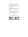
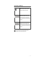
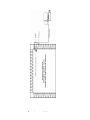
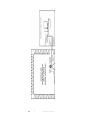
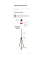
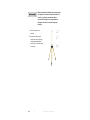
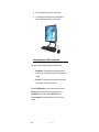
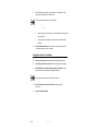
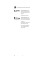
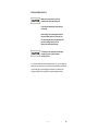
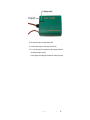
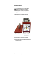
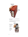
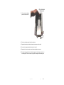
Model 4340 Digital Camera System (CCTV) User Manual ETS-Lindgren Inc. reserves the right to make changes to any product described herein in order to improve function, design, or for any other reason. Nothing contained herein shall constitute ETS-Lindgren Inc. any product or circuit described herein. ETS-Lindgren Inc. does not convey any license under its patent rights or the rights of others. © Copyright 2013 by ETS-Lindgren Inc. All Rights Reserved. No part of this document may be copied by any means without written permission from ETS-Lindgren Inc. Trademarks used in this document: The ETS-Lindgren logo is a trademark of ETS-Lindgren Inc.; Microsoft, Windows, and Internet Explorer are registered trademarks of Microsoft Corporation in the United States and/or other countries; Intel and Pentium are registered trademarks of Intel Corporation. Revision Record MANUAL,4340,PAN CAMERA | Part #399371, Rev. A ii Revision Description Date A Initial Release May, 2013 | Table of Contents Notes, Cautions, and Warnings ................................................ v 1.0 Introduction .......................................................................... 7 Standard Configuration and Components ................................................... 7 Optional Configurations and Additional Components ................................ 10 If You Have a Chamber With A Shielded Control Room .................... 10 If You Have a Tripod Mount .............................................................. 10 If You Have a Multi-Camera System ................................................. 11 Power Supply Options .............................................................................. 12 10/100 Ethernet Filter ....................................................................... 12 Battery Pack and Charger ................................................................. 12 H-491009 Tripod ....................................................................................... 13 About Installation and Setup ..................................................................... 13 Installation and Setup Checklist ........................................................ 14 ETS-Lindgren Product Information Bulletin ............................................... 14 2.0 Maintenance ....................................................................... 15 Replacement and Optional Parts .............................................................. 16 Service Procedures .................................................................................. 17 3.0 Specifications ..................................................................... 19 Camera Enclosure, Converter Enclosure, Dome ....................................... 19 Battery Pack and Charger ......................................................................... 20 Panasonic Network Camera WV-SC385 ................................................... 21 4.0 Pre-Installation Tasks ........................................................ 23 Demonstrate Good Shielding Practices ..................................................... 23 Choose the Camera Location ................................................................... 24 5.0 Install the 10/100 Ethernet Filter ....................................... 25 Overview of 10/100 Ethernet Filter Connections ....................................... 26 Overview of 10/100 Ethernet Filter Operation ........................................... 26 Installing a Schuko Plug ............................................................................ 27 6.0 Wall or Ceiling Mount the Camera ................................... 29 7.0 Install Optional Components ............................................ 33 If You Have a Chamber with a Shielded Control Room ............................. 33 | iii Chamber With Shielded Control Room—Additional Pre-installation Tasks ................................................................................................ 35 Chamber With Shielded Control Room—Installation Tasks ............... 35 If You Have a Tripod Mount (For Use with or without Shielded Control Room)....................................................................................................... 37 Tripod Mount—Additional Pre-Installation Tasks ............................... 39 Tripod Mount—Installation Tasks ...................................................... 39 If You Have a Multi-Camera System (For Use with or without Shielded Control Room) .......................................................................................... 42 Multi-Camera System—Additional Pre-installation Tasks .................. 45 Multi-Camera System—Installation Tasks ......................................... 45 8.0 Computer Setup ................................................................. 47 Minimum Computer Requirements ............................................................ 47 Setup the Computer .................................................................................. 47 Viewing Images from a Multi-Camera System ........................................... 48 9.0 Operation ............................................................................ 49 Operating Notices ..................................................................................... 49 Viewing Images from the Camera ............................................................. 50 If the Camera Stops Working ............................................................ 50 Using Multiple Cameras ............................................................................ 50 Arranging Multi-Camera Images ....................................................... 51 Setting Up a Multi-Screen Configuration ........................................... 51 Setting Resolution & Frame Rate .............................................................. 52 Operating the Battery Pack ....................................................................... 53 Using the Battery Pack...................................................................... 53 Storing the Battery Pack ................................................................... 55 Charging the Battery Pack ................................................................ 56 Replacing the Battery Pack ............................................................... 58 Appendix A: Warranty ............................................................. 63 Appendix B: EC Declaration of Conformity .......................... 65 iv | Notes, Cautions, and Warnings Note: Denotes helpful information intended to provide tips for better use of the product. Caution: Denotes a hazard. Failure to follow instructions could result in minor personal injury and/or property damage. Included text gives proper procedures. Warning: Denotes a hazard. Failure to follow instructions could result in SEVERE personal injury and/or property damage. Included text gives proper procedures. See the ETS-Lindgren Product Information Bulletin for safety, regulatory, and other product marking information. | v This page intentionally left blank. vi | 1.0 Introduction The ETS-Lindgren Model 4340 Digital Camera System (CCTV) is designed to monitor tests conducted in anechoic or reverb chambers and large test cells where moderate EMI field strengths are present. Depending on the configuration, the camera is connected to a personal computer outside the chamber by either Ethernet or fiber optic cables. When the camera and computer are on, the camera image displays in a browser window at the computer. From the browser window you can control these camera features: Pan and tilt—Move the camera lens up and down, and from side to side to create a wide area of vision. Zoom—18x optical zoom with 12x digital/electronic zoom enabling 216x zoom; 36x extra optical zoom under VGA resolution with 12x digital/electronic zoom enabling 432x zoom. Standard Configuration and Components The standard configuration for the Model 4340 CCTV is installed into a chamber without a shielded control room. See the diagram on the following page. Introduction | 7 8 | Introduction The standard configuration for the Model 4340 CCTV includes these components: Panasonic Network Camera WV-SC385—Includes Ethernet cable and power cable connected to camera. Shielded camera enclosure with dome—Includes camera penetration connected to enclosure, and absorber wrap for the enclosure. Mounting hardware—The hardware allows you to mount the camera enclosure from the wall or ceiling, and includes two 12-inch pipe lengths, one 6-inch pipe length, one elbow joint (for wall mount only), four pipe-to-pipe couplers, and absorber wrap for the assembled pipe. 10/100 Ethernet Filter—Provides one Ethernet connector, two fiber optic connectors, an Ethernet-to-fiber optic converter, and a fiber optic to Ethernet converter. Depending on your configuration, the fiber optic to Ethernet converter may be provided as an internal or external converter. Following are the two types of 10/100 Ethernet filters: – LMF-4095 10/100 Ethernet filter—Includes internal fiber optic-to-Ethernet converter. – LMF-4106 10/100 Ethernet filter—Includes external fiber optic-to-Ethernet converter. Personal Computer—Includes monitor, mouse, and keyboard. 10/100 Network Switch—If you ordered a multi-camera configuration, you will install the 10/100 network switch. If you ordered a single-camera configuration, you will not install the switch. In that case, store the 10/100 network switch in a safe location for future expansion of your Model 4340 CCTV. A 30-meter Ethernet cable is included with some configurations. Introduction | 9 Optional Configurations and Additional Components Following are the optional configurations for the Model 4340 CCTV, including a list of additional components required to install the configuration. For diagrams and more information on installing an optional configuration, see Install Optional Components on page 33. IF YOU HAVE A CHAMBER WITH A SHIELDED CONTROL ROOM You need these additional components: Fiber optic-to-Ethernet converter Ethernet cable to connect computer to converter (not included with all configurations) Fiber optic feedthrough connectors 30-meter fiber optic cable 3-meter fiber optic cable IF YOU HAVE A TRIPOD MOUNT For use with or without a shielded control room. You need these additional components: 10 ETS-Lindgren H-491009 tripod Battery pack and charger Fiber optic-to-Ethernet converter Ethernet cable to connect computer to converter (not included with all configurations) Fiber optic feedthrough connectors 30-meter fiber optic cable 3-meter fiber optic cable (only for installations with a shielded control room) | Introduction IF YOU HAVE A MULTI-CAMERA SYSTEM For use with or without a shielded control room. You need these additional components: The number of cameras in a multi-camera configuration may require additional components other than those in the following list. Please contact ETS-Lindgren to configure a multi-camera system. For Use with Shielded Control Room For Use without Shielded Control Room 10/100 Network switch 10/100 Network switch Fiber optic-to-Ethernet converter per camera Ethernet cables—to connect computer to network switch Ethernet cable per converter— to connect computer to network switch, and network switch to each fiber optic-to-Ethernet converter 30-meter Ethernet cable per camera Fiber optic feedthrough connectors per camera 30-meter fiber optic cable per camera 1-meter fiber optic cable per converter Introduction | 11 Power Supply Options The 10/100 Ethernet filter provides the power for all configurations except the tripod mount, which is powered by a battery pack. 10/100 ETHERNET FILTER See the 10/100 Ethernet Filter Installation Manual for all filter information and installation instructions. They are not included in this document. BATTERY PACK AND CHARGER The tripod mount configuration is powered by a battery pack. The battery pack contains a 12V 13Ah Nickel-Metal Hydride (NiMH) battery housed in a shielded case. The battery normally provides up to 12 hours of operation, but operating time may be reduced with extensive use of the pan and tilt and functions. A battery charger and charger cable are included with the battery pack. See Operating the Battery Pack on page 53 for more information. 12 | Introduction H-491009 Tripod The H-491009 tripod includes a 1/4–20 thread center pole and a 3/8-inch thread center pole. Use the 3/8-inch thread center pole to mount the camera onto the tripod. This dielectric tripod is the preferred method for mounting field probes for making unperturbed field measurements. It includes a 1/4–20 UNC threaded stud for mounting any ETS-Lindgren probe with a tripod mount. It is designed with an adjustable center post and a rotating mount. About Installation and Setup This manual provides instructions to install the Model 4340 CCTV into a chamber without a shielded control room, including how to mount the camera on the wall, from the ceiling, or on a tripod. Steps to install the optional components are also included. For a list of optional configurations and components, see Optional Configurations and Additional Components on page 10. To install a configuration of the Model 4340 CCTV other than those described in this manual, please contact ETS-Lindgren for more information. Introduction | 13 INSTALLATION AND SETUP CHECKLIST Complete pre-installation tasks—See page 23. Install the 10/100 Ethernet filter—See page 25. Mount the camera—For wall or ceiling mount, see page 29. For tripod mount, see page 37. Install optional items—See page 33. Set up the computer—See page 47. Operate the camera—See page 49. ETS-Lindgren Product Information Bulletin See the ETS-Lindgren Product Information Bulletin included with your shipment for the following: 14 Warranty information Safety, regulatory, and other product marking information Steps to receive your shipment Steps to return a component for service ETS-Lindgren calibration service ETS-Lindgren contact information | Introduction 2.0 Maintenance Before performing any maintenance, follow the safety information in the ETS-Lindgren Product Information Bulletin included with your shipment. Maintenance of the Model 4340 CCTV is limited to external components such as cables or connectors. WARRANTY Servicing or modifying the camera without ETS-Lindgren authorization may void your warranty. There are no internal user serviceable items. Only qualified personnel should service this equipment. Contact ETS-Lindgren for service. Do not remove the camera from the camera enclosure. Do not attempt to disassemble the camera. See the manual provided with the computer for maintenance recommendations. If you have any questions concerning maintenance, contact ETS-Lindgren Customer Service. Maintenance | 15 Replacement and Optional Parts ETS-Lindgren may substitute a similar part or new part number with the same functionality for another part/part number. Contact ETS-Lindgren for questions about part numbers and ordering parts. Following are the part numbers for ordering replacement or optional parts for the Model 4340 CCTV. 16 Part Description Part Number DCCTV System, for use without shielded control room—Includes computer, includes computer monitor 4340-01 DCCTV System, for use without shielded control room—Includes computer, does not include computer monitor 4340-01XMON DCCTV System, for use without shielded control room—Does not include computer, does not include computer monitor 4340-01XPC DCCTV System for use with shielded control room—Includes computer, includes computer monitor 4340-02 DCCTV System for use with shielded control room—Includes computer, does not include computer monitor 4340-02XMON DCCTV System for use with shielded control room—Does not include computer, does not include computer monitor 4340-02XPC DCCTV System, Tripod Configuration, for use with or without shielded control room—Includes computer, includes computer monitor 4340-03 DCCTV System, Tripod Configuration, for use with or without shielded control room—Includes computer, does not include computer monitor 4340-03XMON | Maintenance Part Description Part Number DCCTV System, Tripod Configuration, for use with or without shielded control room—Does not include computer, does not include computer monitor 4340-03XPC DCCTV Camera, Pan and Tilt 111095 LMF-4095 10/100 Ethernet Filter, for use without shielded control room, includes internal fiber optic-to-Ethernet converter E-LMF-4095 LMF-4106 10/100 Ethernet Filter, for use with shielded control room, includes external fiber optic-to-Ethernet converter E-LMF-4106 Computer, DCCTV Monitor and Controller 707033 Tripod H-491009 Battery Pack, Enclosure, and Battery Charger 111589 Battery Pack only 400041 Battery Charger only H-491198-120 10/100 Network Switch 707037 Fiber Optic-to-Ethernet Converter 708043 30-meter Ethernet Cable 675298 30-meter Fiber Optic Cable 705344-30 3-meter Fiber Optic Cable 705344-3 Fiber Optic Feedthrough Connector 708027 PSE Power Cord (Japan only) 670040 Service Procedures For the steps to return a system or system component to ETS-Lindgren for service, see the Product Information Bulletin included with your shipment. Maintenance | 17 This page intentionally left blank. 18 | Maintenance 3.0 Specifications Camera Enclosure, Converter Enclosure, Dome The converter enclosure is included only with a tripod configuration. Enclosure/Dome Shielding: Up to 200 Volts per meter (V/m) 14°F to 104°F Operating Temperature: (–10°C to 40°C) Height: 7.82 cm (3.08 in) Dome Dimensions Radius: 7.82 cm (3.08 in) Diameter: 16.57 cm (6.525 in) Camera Enclosure Dimensions Height: 9.685 cm (3.813 in) Microphone Camera Enclosure Connectors: Line-out Diameter: 21.9 cm (8.625 in) Converter Enclosure Dimensions Height: 6.35 cm (2.5 in) Specifications | 19 Battery Pack and Charger The battery pack and charger are included only with a tripod configuration. Width: 12.7 cm (5.0 in) Length: 25.4 cm (10.0 in) Battery Pack Dimensions: Height (with handle): 17.18 cm (6.765 in) Height (without handle): 12.28 cm (4.835 in) 12V 13Ah Nickel-Metal Hydride (NiMH), rechargeable Battery Type: 20 F battery pack, 13000 mAH (rapid charge cells, 1.2 volts/cell) Battery Life: Up to 12 hours, depending on use of pan and tilt functions Battery Charger: For 12V Nickel-Metal Hydride (NiMH) batteries | Specifications Panasonic Network Camera WV-SC385 For a complete list of camera specifications, see the separate Panasonic camera manual. SXVGA: 1280 x 960 Image Size: Maximum Frames Per Second (FPS): VGA: 640 x 480 (default) Up to 30 FPS Range: 0º to 350º Pan: Speed (manual): 0.5º to 100º per second (approximate) Range: -30º to 90º (upward-level-downward) Tilt: Speed (manual): 0.5º to 100º per second (approximate) 18x optical zoom with 12x digital/electronic zoom enabling 216x zoom Zoom Ratio: 36x extra optical zoom under VGA resolution with 12x digital/electronic zoom enabling 432x zoom 10/100 Ethernet (RJ45) Audio output Connectors: Monitor out Microphone/line input Specifications | 21 14°F to 122°F Operating Temperature: (–10°C to 50°C) Height: 155 mm (6.09 in) Physical Dimensions: Diameter: 115 mm (4.53 in) Weight: 900 grams (1.99 lb) 22 | Specifications 4.0 Pre-Installation Tasks Before installing any components, follow the safety information in the ETS-Lindgren Product Information Bulletin included with your shipment. Prior to installing the Model 4340 Digital Camera System (CCTV), complete these pre-installation tasks. If you are installing one of the optional configurations listed under Optional Configurations and Additional Components on page 10, additional pre-installation tasks may be required. For a description of pre-installation tasks for optional configurations, see Install Optional Components on page 33. Demonstrate Good Shielding Practices Certain guidelines must be followed to retain the RF shielding integrity of the chamber. These good shielding practices consist of the following: Doors must be periodically cleaned and lubricated. Screw-retaining items mounted within the enclosure must not penetrate through both shields of a modular panel system. Screws must not penetrate the screen system of a Series 60 at all. Framing screws must never be used to fasten items within the enclosure. When a hole is bored for a new penetration, all burrs must be removed and both the perimeter of the hole and the penetration must be cleaned with a cleaning agent before installing the new penetration. Nothing must penetrate the enclosure wall, floor, or ceiling without use of a proper electromagnetic-designated penetration. Pre-Installation Tasks | 23 Choose the Camera Location You will install the 10/100 Ethernet filter on the outside of the chamber at the source of power, and the camera will mount to the filter penetration inside the chamber. Verify that the view from the selected location is obstruction-free, especially if absorber cones are in the vicinity. A tripod-mounted camera receives power from the battery pack, so a 10/100 Ethernet filter is not provided. The standard mounting hardware for the Model 4340 CCTV includes two 12-inch pipe lengths, one 6-inch pipe length, one elbow joint (for wall mount only), and four pipe-to-pipe couplers. When installing the camera in a chamber with absorber cones, the camera enclosure should extend just past the tips of the cones. These pipe lengths can be assembled in a variety of lengths to accommodate most configuration requirements. 24 | Pre-Installation Tasks 5.0 Install the 10/100 Ethernet Filter Before installing any components, follow the safety information in the ETS-Lindgren Product Information Bulletin included with your shipment. See the 10/100 Ethernet Filter Installation Manual for the pre-installation requirements and installation instructions for the filter. They are not included in this document. If you do not install an on/off power switch, the camera is powered on at all times. This does not apply to battery-operated cameras in a multi-camera configuration. Install the 10/100 Ethernet Filter | 25 Overview of 10/100 Ethernet Filter Connections Overview of 10/100 Ethernet Filter Operation Following is an overview of the functions of the 10/100 Ethernet filter. To see the locations of the referenced connections and components, refer to the diagram on page 26. 1. 26 AC power enters the 10/100 Ethernet filter, and then enters the power supply module, where the AC power is converted to 12V DC power. One line of the converted DC power enters the filter module, and a second line powers the fiber optic-to-Ethernet converter (not present in all configurations). | Install the 10/100 Ethernet Filter 2. 3. Clean DC power emerges from the filter module to the clean side of the 10/100 Ethernet filter as two connectors: Power connector for camera—The power cable from the camera plugs into this power connector. Power connector for Ethernet-to-fiber optic converter—This power connector plugs into the converter. The Ethernet cable from the camera also plugs into the converter. Internal fiber optic cables extend from the external fiber optic connectors on the dirty side of the 10/100 Ethernet filter to the clean side. On the clean side, internal fiber optic cables plug into the Ethernet-to-fiber optic converter. Depending on your configuration, external fiber optic cables may plug into the external fiber optic connectors. Installing a Schuko Plug If required by your country location, install a Schuko plug with the installation of the 10/100 Ethernet filter. 1. Remove the access cover. Install the 10/100 Ethernet Filter | 27 2. Turn the top of the strain relief until the strain relief is loosened from the power cord. 3. Remove the terminal ring and spade lugs from filter. 4. Remove the cord from the filter. 5. Replace with a Schuko plug and cord. 6. Using the provided spare terminal ring and spade lugs, wire the ground wire and power wires, as required. 7. Tighten the strain relief around the power cord, and replace the access cover. 28 | Install the 10/100 Ethernet Filter 6.0 Wall or Ceiling Mount the Camera Before installing any components, follow the safety information in the ETS-Lindgren Product Information Bulletin included with your shipment. Before you mount the camera, complete the installation of the 10/100 Ethernet filter. See the 10/100 Ethernet Filter Installation Manual for the pre-installation requirements and installation instructions for the filter. They are not included in this document. Follow these instructions to mount the camera from the wall or ceiling. To mount the camera on a tripod, see If You Have a Tripod Mount on page 37. 1. Assemble the two 12-inch and one 6-inch pipe lengths as required by your installation, and connect them with the pipe-to-pipe couplers. Manually tighten the couplers. Do not use the elbow joint if mounting the camera from the ceiling. 2. Run the power cable and the Ethernet cable from the camera through the pipe. Wall or Ceiling Mount the Camera | 29 3. Connect the assembled pipe to the filter penetration with a pipe-to-pipe coupler, running the cables through the penetration to the 10/100 Ethernet filter outside the chamber. Manually tighten the coupler to secure the pipe. 4. Connect the camera enclosure to the assembled pipe. If wall-mounting the camera, screw the camera penetration onto the elbow joint at the end of the pipe. Tighten the locking nut with a wrench. 30 | Wall or Ceiling Mount the Camera If mounting the camera from the ceiling, connect the camera penetration to the pipe with a pipe-to-pipe coupler. Manually tighten the coupler, and then tighten the locking nut with a wrench. Point ETS-Lindgren label to center of desired field of vision When the camera enclosure is completely connected to the pipe, the ETS-Lindgren label on the enclosure should point to the center of the desired field of vision. 5. If the ETS-Lindgren label does not point to the center of the desired field of vision, slightly loosen the camera penetration nut and locking nut to rotate the camera enclosure so the label is in the correct location, and then securely retighten both nuts. Wall or Ceiling Mount the Camera | 31 6. Plug the Ethernet cable from the camera into the connector on the Ethernet-to-fiber optic converter in the 10/100 Ethernet filter, and then plug the power cable from the camera into the keyed power connector cable from the converter. For a diagram of filter connections, see page 26. 7. Provide additional shielding by encircling the enclosure and assembled pipe with the provided absorber wrap. To install optional components, see page 33. To set up the computer, see page 47. 32 | Wall or Ceiling Mount the Camera 7.0 Install Optional Components Before installing any components, follow the safety information in the ETS-Lindgren Product Information Bulletin included with your shipment. To install the following configurations and components: If you have a chamber with a shielded control room—See the next section. If you have a tripod mount (for use with or without a shielded control room)—See page 37. If you have a multi-camera system (for use with or without a shielded control room)—See page 42. A 10/100 network switch is included with your order. If you are installing a multi-camera configuration, you will install the 10/100 network switch. If you are installing a single-camera configuration, you will not install the switch. In that case, store the 10/100 network switch in a safe location for future expansion of your Model 4340 Digital Camera System (CCTV). If You Have a Chamber with a Shielded Control Room In addition to mounting the camera from the wall or ceiling, a shielded control room requires you to install a fiber optic-to-Ethernet converter, an Ethernet cable, fiber optic cables, and fiber optic feedthrough connectors. See the diagram on the following page. To set up the computer, see page 47. Install Optional Components | 33 34 | Install Optional Components CHAMBER WITH SHIELDED CONTROL ROOM—ADDITIONAL PRE-INSTALLATION TASKS Install the fiber optic feedthrough connectors in the wall of the shielded control room. CHAMBER WITH SHIELDED CONTROL ROOM—INSTALLATION TASKS 1. Remove the access cover. Install Optional Components | 35 Your 10/100 Ethernet filter may have shipped with an external fiber optic-to-Ethernet converter, and the fiber optic cables connected internally. If so, skip step 2 and step 3 in the following instructions. 2. Disconnect the fiber optic cables from the fiber optic-to-Ethernet converter. Plug the cables into the internal fiber optic connectors. 3. Remove the fiber optic-to-Ethernet converter from the 10/100 Ethernet filter. 4. Place the fiber optic-to-Ethernet converter in the same location as the personal computer. 5. Connect an Ethernet cable from the computer to the converter. 6. Connect two fiber optic cables to the converter and run the cables through the feedthrough connectors. 7. Plug the fiber optic cables into the external fiber optic connectors on the 10/100 Ethernet filter. 36 | Install Optional Components If You Have a Tripod Mount (For Use with or without Shielded Control Room) A tripod mount configuration requires you install a tripod, battery pack, fiber optic-to-Ethernet converter, an Ethernet cable, fiber optic cables, and fiber optic feedthrough connectors. The fiber optic-to-Ethernet converter is housed in the shielded enclosure attached to the camera enclosure, requiring no additional assembly. See the diagram on the following page. To set up the computer, see page 47. Install Optional Components | 37 38 | Install Optional Components TRIPOD MOUNT—ADDITIONAL PRE-INSTALLATION TASKS Install the fiber optic feedthrough connectors in the wall of the chamber. If you have a shielded control room, also install fiber optic feedthrough connectors in the wall of the control room. TRIPOD MOUNT—INSTALLATION TASKS The H-491009 tripod includes a 1/4–20 thread center pole and a 3/8-inch thread center pole. Use the 3/8-inch thread center pole to mount the camera onto the tripod. Install Optional Components | 39 While performing the following steps, always protect and support the camera and camera enclosure. Do not roll, jar, or drop the camera and camera enclosure. ETS-Lindgren is not responsible for damage to the camera as a result of improper handling. 1. Set up the tripod in the chamber. 2. Remove the 3/8-in thread center pole from the tripod by rotating the height adjuster knob to loosen, and then lifting the pole up. 40 | Install Optional Components 3. Place the camera and camera enclosure in a stable location to prevent it from rolling or falling. Securely support the camera and enclosure, and rotate the 3/8-in thread center pole into the threaded connector on the bottom of the enclosure. 4. Supporting the camera and enclosure, carefully re-insert the 3/8-in thread center pole into the tripod. When the center pole is at the desired height, rotate the height adjuster knob to tighten. 5. Place the fiber optic-to-Ethernet converter in the same location as the personal computer. 6. Connect an Ethernet cable from the computer to the converter. 7. Connect two fiber optic cables to the converter and run the cables through the feedthrough connectors to the location of the camera and tripod in the chamber. If you have a shielded control room, you will run the cable through two sets of feedthrough connectors to the camera and tripod. 8. Plug the fiber optic cables into the fiber optic connectors on the bottom of the converter enclosure. 9. Place the battery pack on the chamber floor next to the tripod. Plug one end of the power cable into the battery pack, and the other end into the power connector on the bottom of the converter enclosure. You must charge the battery pack before using it for the first time. See Charging the Battery Pack on page 56 for complete charging information. Install Optional Components | 41 If You Have a Multi-Camera System (For Use with or without Shielded Control Room) In addition to mounting the cameras from the wall or ceiling, a multi-camera configuration without a shielded control room requires you to install a 10/100 network switch and Ethernet cables. See the diagrams on the following pages. To set up the computer for a multi-camera system, see Computer Setup on page 47 and Viewing Images from a Multi-Camera System on page 48. 42 | Install Optional Components Install Optional Components | 43 If you have a shielded control room, also install a 10/100 network switch, one fiber optic-to-Ethernet converter per camera, Ethernet cables, fiber optic cables, and fiber optic feedthrough connectors. 44 | Install Optional Components MULTI-CAMERA SYSTEM—ADDITIONAL PRE-INSTALLATION TASKS For a multi-camera configuration, you will need to install one 10/100 Ethernet filter per camera, in addition to mounting the cameras. Install filters— Follow the 10/100 Ethernet filter installation instructions in the separate document, 10/100 Ethernet Filter Installation Manual. They are not included in this document. Mount cameras—Follow the instructions to wall-mount or ceiling-mount a camera on page 29. If you have a shielded control room, also install fiber optic feedthrough connectors in the wall of the control room. MULTI-CAMERA SYSTEM—INSTALLATION TASKS 1. Place the 10/100 network switch in the same location as the personal computer. 2. Plug the Ethernet cable from the computer into any of the numbered connectors on the network switch. Install Optional Components | 45 3. If you do not have a shielded control room— Plug one Ethernet cable for each camera into any of the numbered connectors on the network switch. Run each cable to a 10/100 Ethernet filter. Plug the cable into the external Ethernet connector on the 10/100 Ethernet filter. For a diagram of filter connections, see page 26. If you have a shielded control room—Follow the steps listed in Chamber With Shielded Control Room—Installation Tasks on page 35 to install the fiber optic-to-Ethernet converter. 46 | Install Optional Components 8.0 Computer Setup Before connecting any components, follow the safety information in the ETS-Lindgren Product Information Bulletin included with your shipment. Minimum Computer Requirements If you purchased a Model 4340 Digital Camera System (CCTV) configuration from ETS-Lindgren that includes a personal computer, the following requirements are met. If you plan to install a computer other than one provided by ETS-Lindgren, verify that it meets these minimum requirements: Microsoft® Windows® Operating System Internet Explorer® Browser 7 Professional (64 bit/32 bit) 8.0 Vista Business SP1 (32 bit) 7.0 XP Professional SP3 6.0 SP3 Setup the Computer If you install a computer other than one provided by ETS-Lindgren, see the separate Panasonic camera manual for complete information on setting up the computer and IP address, and installing additional software. If you purchased a Model 4340 CCTV configuration from ETS-Lindgren that includes a personal computer, follow these steps: 1. Follow the instructions included with the computer to set it up in the desired location, and to connect the monitor, keyboard, and mouse. 2. Follow the computer instructions to connect the Ethernet cable and power cables, and to connect the computer and monitor to power. Computer Setup | 47 3. Follow the computer instructions to turn on the computer. 4. Internet Explorer automatically loads, links to the IP address of camera, and displays the current view from the camera. Viewing Images from a Multi-Camera System There are two options for viewing the images from multiple cameras: Multi Windows—This setting opens a separate Internet Explorer window for each camera. Each window can be individually resized as required. Multi View—This setting opens one Internet Explorer window that is split into sections, one section for each camera. Because the Multi Windows view provides a faster response time than the Multi View, typically the default view for a multi-camera system is the Multi Windows view. If you want to change to Multi View, click the Screen changeover button located in the upper right corner of any of the windows. 48 | Computer Setup 9.0 Operation Before connecting any components, follow the safety information in the ETS-Lindgren Product Information Bulletin included with your shipment. Operating Notices Before placing the Model 4340 Digital Camera System (CCTV) into service, follow these precautions: Never face the camera towards any bright or reflective light. This may cause a smear on the picture and possible damage to the charge-coupled device (CCD). Do not expose the camera to moisture, or place the camera in an area where condensation may form. Moisture will cause damage to the internal components of the camera and create an electrical shock hazard. Do not manually move the pan and tilt head. This may cause irreparable damage to the internal mechanism. For complete information on using the camera, including viewing, recording, and playback, see the separate Panasonic camera manual. Operation | 49 Viewing Images from the Camera When the camera is powered on, it will take up to one minute to start up. To view an image from the camera, simply turn on your computer. With the current view from the camera displayed in Internet Explorer®: 1. Click on the area of the screen that you want to view, and the camera pans and tilts to the specified area. 2. Zoom in and out on the current view by rotating the roller wheel on the mouse. IF THE CAMERA STOPS WORKING If the camera suddenly shuts off during operation, turn off the battery pack and charge it. See Charging the Battery Pack on page 56 for complete charging information. If the battery pack is fully charged and the camera still will not turn on, contact ETS-Lindgren for assistance. Using Multiple Cameras To set up a multi-camera configuration using one Internet Explorer browser window per camera, see Arranging Multi-Camera Images on page 51. To set up a multi-camera configuration using one Internet Explorer browser window for all cameras, see Setting Up a Multi-Screen Configuration on page 51. 50 | Operation ARRANGING MULTI-CAMERA IMAGES 1. Power up all cameras. Allow cameras to complete self-test routine. 2. Open Internet Explorer and type IP address of one camera. Type the IP address for one camera in the address bar in the browser window. 3. Open a second Internet Explorer browser window and type the next IP address. Repeat this step until you open a browser window for each camera on the network. 4. Arrange browser windows. Drag windows to desired location on monitors. Re-size windows as required. SETTING UP A MULTI-SCREEN CONFIGURATION You can configure up to four cameras as a group and up to four groups, for a maximum of 16 cameras. 1. Power up all cameras. Allow cameras to complete self-test routine. 2. Select desired configuration. On the camera home screen, click the button under Multi-screen that corresponds to the desired image configuration. 3. Enter the IP address or the host name. Click Setup and enter the information for the first camera, using a maximum of 128 characters. For example: For an IPv4 address: http://192.168.0.10:8080 For an IPv6 address: http://[2001:db8:0:0:0:0:0:1]:8080 When using the host name, it is necessary to configure the DNS settings of the computer that will be used for the multi-screen display (IPv4 network). If you purchased the computer from ETS-Lindgren, it was shipped to you pre-configured. Operation | 51 4. Enter the title of the camera, using a maximum of 20 characters. The camera title will display on the multi-screen. Do not use these characters in the camera title: 5. " & When selecting a 16-split screen, some characters of the camera title may not display. The multi-screen will display in 4:3 aspect ratio even when 16:9 is selected. Complete Setup information. Enter the rest of the setup information on the camera home screen, as desired. Setting Resolution & Frame Rate 1. Power up all cameras. Allow cameras to complete self-test routine. 2. Click Setup and then click General. The settings window will display. 3. Set Resolution to the desired setting and then click Save. Set and save the resolution setting before setting the frame rate. Optical zoom increases when using a lower resolution. 52 4. Set Frame Rate to 30 and then click Save. Set and save the frame rate. 5. Close the settings window. | Operation Operating the Battery Pack You must charge the battery pack before using it for the first time. See Charging the Battery Pack on page 56 for complete charging information. USING THE BATTERY PACK The power button located on the battery pack functions as an on/off switch for the battery pack and the camera. When you are using the camera, the button should be in the on position. When the camera is off or the battery pack is in storage, the button should be in the off position. See Storing the Battery Pack on page 55 for the charging requirements for battery pack storage. Operation | 53 Turn off the battery pack before connecting or disconnecting cables. To turn the battery pack on—Push the power button in to depress the button. In this position, the battery pack will continuously supply power. (For operation) Select this setting to use the camera. (For charging and storage) To turn the battery pack off—Push the power button in and then release it to the off position. In this position, the battery pack will not supply power. Select this setting to turn off the camera or to place the battery pack into storage. See the next section, Storing the Battery Pack, for the charging requirements for battery pack storage. 54 | Operation STORING THE BATTERY PACK Make sure the power button is in the off position before storing the battery pack. Fully charge the battery pack before placing it into storage. When storing it for an extended period of time, charge the battery pack once per month. Over time the battery pack will slowly discharge, and permanent damage could occur if the battery pack completely discharges. ETS-Lindgren is not responsible for damage to the battery pack as a result of improper handling and care. If you store the battery pack for an extended period of time, you must charge the battery pack once per month. If stored without periodically charging, the batteries could lose the ability to hold a charge and would need to be replaced. See Charging the Battery Pack on page 56 for complete charging information. Operation | 55 CHARGING THE BATTERY PACK You must charge the battery pack before using it for the first time. You may charge the battery pack inside or outside the chamber. If charging the battery pack inside the chamber, do not perform any testing while charging is in progress. The battery pack normally provides up to 12 hours of operation, but operating time may be reduced with extensive use of the pan and tilt and functions. It can take up to 24 hours to fully charge the battery pack. Following are the steps: 1. Make sure the power button on the battery pack is in the off position. 2. Disconnect the camera power cable from the battery pack. 3. Plug the charging cable from the battery charger into the battery pack. 56 | Operation 4. Slide the selector switch on the battery charger to 1.8A. 5. Connect the battery charger to a mains supply (100 or 240 VAC). 6. Turn on the mains supply. The charge light on the battery charger will illuminate red, indicating a charge is in progress. Continue charging until the charge light illuminates green, indicating a full charge. Operation | 57 REPLACING THE BATTERY PACK At end of useful life, please recycle the used batteries, or dispose of them safely and properly. Many cities collect used batteries for recycling or disposal. You may contact your local waste disposal agency for information on battery recycling and disposal. 1. Make sure the power button on the battery pack is in the off position. 2. Disconnect the cable from the power connector on the battery pack. 3. Remove the screws from the lid of the battery pack enclosure, and then lift the lid to remove it from the enclosure. 58 | Operation 4. Inside the enclosure, disconnect the two charging cables by separating each cable at the middle connector. Operation | 59 5. Place the enclosure on one side, and remove the two bracket screws from the bottom of the enclosure. To prevent the battery pack from shifting inside the enclosure while removing the bracket screws, support the pack with your hand. 6. Place the enclosure on the bottom, and carefully move the bracket towards the front of the enclosure. Avoid placing stress on the charging cables as you move the bracket. 60 | Operation 7. Lift to remove the battery pack from the enclosure. 8. Place the new battery pack inside the enclosure. 9. Replace the bracket, and then the bracket screws removed in step 5. 10. Connect the charging cables disconnected in step 0. 11. Replace the lid on the enclosure, and insert and tighten the screws. 12. Plug the charging cable from the battery charger into the charger connector on the battery pack. Follow the steps on page 56 to charge the new battery pack. Operation | 61 This page intentionally left blank. 62 | Operation Appendix A: Warranty See the Product Information Bulletin included with your shipment for the complete ETS-Lindgren warranty for your Model 4340 Digital Camera System (CCTV). DURATION OF WARRANTIES FOR MODEL 4340 CCTV All product warranties, except the warranty of title, and all remedies for warranty failures are limited to two years. Product Warranted Duration of Warranty Period Model 4340 Digital Camera System (CCTV) 2 Years Warranty | 63 This page intentionally left blank. 64 | Warranty Appendix B: EC Declaration of Conformity The EC Declaration of Conformity is the method by which ETS-Lindgren Inc. declares that the equipment listed on this document complies with the EMC Directive and Low Voltage Directive. Factory Issued by ETS-Lindgren Inc. 1301 Arrow Point Drive Cedar Park, TX, USA 78613 ETS-Lindgren Inc. 1301 Arrow Point Drive Cedar Park, TX, USA 78613 The products listed below are eligible to bear the CE mark: – Model 4340 Digital Camera System (CCTV) APPLICABLE REQUIREMENTS AUTHORIZED SIGNATORIES The authorizing signatures on the EC Declaration of Conformity document authorize ETS-Lindgren Inc. to affix the CE mark to the indicated product. CE marks placed on these products will be distinct and visible. Other marks or inscriptions liable to be confused with the CE mark will not be affixed to these products. ETS-Lindgren Inc. has ensured that appropriate documentation shall remain available on premises for inspection and validation purposes for a period of no less than 10 years. EC Declaration of Conformity | 65