1
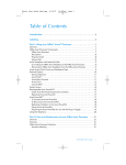
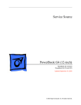
Service Source Power Mac G4 Cube Updated June 2, 2003 © 2002 Apple Computer, Inc. All rights reserved. Service Source Take Apart Power Mac G4 Cube © 2002 Apple Computer, Inc. All rights reserved. General Instructions Tools The following tools are recommended for the Take Apart procedures: • ESD wriststrap and mat • Flat -blade screwdriver • Magnetized Phillips screwdriver • Torx T8 screwdriver • Torx T10 screwdriver • Pliers • Jeweler’s Phillips screwdriver • Black stick (or other nonconductive plastic or nylon tool) Note: To organize the screws you remove from the assembly, use a tray with divided compartments (such as a plastic ice cube tray). Serial Number Location In this computer, the product serial number is located on the base near the computer latch. General Instructions Power Mac G4 Cube Take Apart - 1 Computer Enclosure Tools No tools are required for this procedure. Preliminary Steps Before you begin, turn off the computer. Procedure Warning: Always turn off the computer before opening it to avoid damaging its internal components. 1. Place the computer on a clean, flat surface. 2. Shut down the computer, and wait five minutes for the computer’s internal components to cool down. 3. Unplug all cables from the computer except the power cord. Note: If you have never plugged in the computer, connect the computer’s power cord and plug it in. 4. Turn the computer on its side on a soft, clean cloth, and ground yourself by touching the bare metal between the video ports. Touch Bare Metal 2 - Power Mac G4 Cube Take Apart Computer Enclosure Important: To avoid electrostatic discharge, always ground yourself by touching the bare metal before you touch any parts or install any components inside the computer. To avoid static electricity building back up in your body, do not walk around the room until you have completed the installation and closed the computer. 5. Unplug the power cord. 6. Turn the computer upside down, and push down on the latch to release it. Allow the latch to extend completely. Extended Latch Latch 7. Gently pull the core from the computer enclosure and place the core on a soft cloth. Core Enclosure Computer Enclosure Power Mac G4 Cube Take Apart - 3 8. Holding the core by the latch, insert the core into the replacement enclosure. Note: The core fits into the enclosure only one way. Position the core so the ports are toward the back of the enclosure. Core Enclosure 9. With a flat hand, press down on the latch until it locks into place. Firmly press the core to ensure it is fully secured within the enclosure. Important: Do not lift or carry your computer by the core latch. The enclosure could fall off the core and be damaged. Latch 10. Turn the computer upright and reconnect all cables. Warning: Never turn on the computer unless all of its internal and external parts are in place and it is closed. Operating the computer when it is open or missing parts can damage the computer or cause injury. 4 - Power Mac G4 Cube Take Apart Computer Enclosure Battery Tools No tools are required for this procedure. Preliminary Steps Before you begin, remove the computer core from the enclosure. Procedure 1. Note the orientation of the installed battery’s positive (+) end. (Positive and negative signs are also marked on the battery holder.) 2. Use your finger to gently pry the battery out of the holder and out of the computer. Warning: Batteries contain chemicals, some of which may be harmful to the environment. Please dispose of used batteries according to your local environmental laws and guidelines. Do not return used batteries to Apple. Positive End Battery 3. Insert the replacement battery into the holder, making sure the battery’s positive and negative signs align with those on the holder. Warning: Installing the battery incorrectly may cause an explosion. Be sure the battery’s positive and negative poles are correctly oriented in the holder. Use Battery Power Mac G4 Cube Take Apart - 5 only the battery supplied. 4. Reassemble and test the computer. Warning: Never turn on the computer unless all of its internal and external parts are in place and it is closed. Operating the computer when it is open or missing parts can damage the computer or cause injury. 6 - Power Mac G4 Cube Take Apart Battery Power Button Gasket Tools No tools are required for this procedure. Preliminary Steps Before you begin, remove the computer core from the enclosure. Power Button Gasket Power Mac G4 Cube Take Apart - 7 Procedure 1. Place your hand in the computer enclosure and lift out the installed gasket. Gasket Enclosure 2. Insert the replacement power button gasket into the recessed area that encircles the power button. 3. Press the gasket into place to ensure that it is secure. 4. Reassemble and test the computer. Warning: Never turn on the computer unless all of its internal and external parts are in place and it is closed. Operating the computer when it is open or missing parts can damage the computer or cause injury. 8 - Power Mac G4 Cube Take Apart Power Button Gasket AirPort Card Tools No tools are required for this procedure. Preliminary Steps Before you begin, remove the computer core from the enclosure. Procedure 1. Disconnect the coaxial antenna cable from the port on the end of the AirPort Card. 2. Pull the plastic tab on the end of the AirPort Card to release the AirPort Card from the PCI card connector. AirPort Card AirPort Card Connector ort AirP Pull Tab Antenna Port on AirPort Card Antenna Cable 3. Insert the replacement AirPort Card through the opening in the PCI card guide and into the connector on the logic board. 4 AirPort Card Carefully attach the coaxial antenna cable to the port on the end of the AirPort Card. Power Mac G4 Cube Take Apart - 9 Note: The antenna cable might be stowed on the side of the PCI card guide. Do not bend or crimp the cable tightly. 5. Reassemble and test the computer. Warning: Never turn on the computer unless all of its internal and external parts are in place and it is closed. Operating the computer when it is open or missing parts can damage the computer or cause injury. 10 - Power Mac G4 Cube Take Apart AirPort Card Memory (DRAM DIMM) Tools No tools are required for this procedure. Preliminary Steps Before you begin, remove the computer core from the enclosure. Procedure 1. If provided, attach the grounding wrist strap included with the replacement memory. 2. Push down the ejectors on the slot of the DIMM you want to replace. Note: The slot might have one or two ejectors. 3. Lift the DIMM out of the computer. Warning: When removing or installing the DIMM, do not touch its connectors. Handle the DIMM only by the edges. DRAM DIMM Connectors Ejector DRAM Slot Memory (DRAM DIMM) Power Mac G4 Cube Take Apart - 11 4. Remove the replacement DIMM from its static-proof bag, taking care not to touch the connectors or chips. 5. Align the replacement DIMM in the DIMM slot. Press the DIMM down firmly until you feel it securely attach to the slot, and the ejectors lock it into place. 6. Reassemble and test the computer. Warning: Never turn on the computer unless all of its internal and external parts are in place and it is closed. Operating the computer when it is open or missing parts can damage the computer or cause injury. 12 - Power Mac G4 Cube Take Apart Memory (DRAM DIMM) ATA Hard Drive Tools This procedure requires the following tools: • Flat-blade screwdriver • Torx T8 screwdriver • Phillips screwdriver Preliminary Steps Before you begin, remove the following: • Computer core from enclosure • AirPort Card, if installed Procedure 1. Press and hold the door latch, and then open the AirPort shield door. . Door Latch ATA Hard Drive Power Mac G4 Cube Take Apart - 13 2. With the AirPort shield door open, pull the tab to disconnect the ATA ribbon cable connector from the hard drive. 3. Disconnect the power cable connector from the hard drive. (You might need to use a flat-blade screwdriver to pry up and loosen the connector.) Pull Tab Connector Connector Door 14 - Power Mac G4 Cube Take Apart ATA Hard Drive 4. Push in the core latch, and reposition the computer chassis so you can access the heatsink and hard drive. 5. Loosen, but do not remove, the three captive screws at the heatsink. 6. Lift up the loosened heatsink, and slide the hard drive out of the carrier. Screws Heatsink Hard Drive 7. Position the replacement drive on the drive carrier so that the ribbon cable and power cable connectors align with the slots at the end of the carrier. 8. Lift up the heatsink, and slide in the drive. 9. Align the heatsink fins to the opposite heatsink fins. Tighten the three captive screws. ATA Hard Drive Power Mac G4 Cube Take Apart - 15 10. Reconnect the power cable connector and the ATA ribbon cable connector to the drive. Pull Tab Connector Connector Door 11. Close the AirPort shield door, and press it down so the door latch engages. Door Latch 12. Reinstall the AirPort Card, if applicable. 13. Reassemble and test the computer. Warning: Never turn on the computer unless all of its internal and external parts are in place and it is closed. Operating the computer when it is open or missing parts can damage the computer or cause injury. 16 - Power Mac G4 Cube Take Apart ATA Hard Drive Plastic Shell from Enclosure Tools This procedure requires the following tools: • Phillips screwdriver • Torx T8 screwdriver Preliminary Steps Before you begin, remove the computer core from the enclosure. Procedure 1. Looking into the computer enclosure, remove the two Phillips screws near the sides of the enclosure. Plastic Shell from Enclosure Power Mac G4 Cube Take Apart - 17 2. Loosen—but do not remove—the four Torx screws at the grill. 3. Notice that each screw has a grommet, and the round base of the grommet has one flat edge. To unlock the enclosure liner, turn the grommet so the flat edge is flush with the side of the grill. Repeat for all grommets. 4. To protect the outside surface of the metal liner, place your hands inside the liner to lift it straight up and out of the shell. 18 - Power Mac G4 Cube Take Apart Plastic Shell from Enclosure 5. Lift the plastic shell off of the grill. 6. Position the replacement plastic shell over the grill. 7. Before installing the liner in the shell, check that the power button is in place. If the power button gasket assembly has slipped out of the socket, install it under the gray cover sheet. Hold it in place as you slide the liner in the replacement shell. 8. Turn the grommets so that a corner of their flat edge locks the grill into place. Hold each grommet in that position as you tighten the Torx screws. 9. Install the two Phillips screws. Plastic Shell from Enclosure Power Mac G4 Cube Take Apart - 19 10. Caution: If the power button gasket assembly is not centered correctly in the shell, the computer might not power up. Make sure the power button gasket assembly is level and centered in place. 11. Reassemble and test the computer. Warning: Never turn on the computer unless all of its internal and external parts are in place and it is closed. Operating the computer when it is open or missing parts can damage the computer or cause injury. 20 - Power Mac G4 Cube Take Apart Plastic Shell from Enclosure Top Plate Assembly with Power Button Gasket Tools The only tool required for this procedure is a Torx T10 screwdriver. Preliminary Steps Before you begin, remove the computer core from the enclosure. Procedure 1. Press the latch in, and turn over the core so the power button faces up. 2. Remove the four corner screws that secure the top plate to the four vertical posts. 3. Remove the four screws on the two sides. (The two screws that align with the vertical plates are much longer than the other screws.) Top Plate Assembly with Power Button Gasket Power Mac G4 Cube Take Apart - 21 4. Lift out the LED cover that is fitted over the power button LED. Set the LED cover aside for installation on the new top plate assembly. 5. Carefully lift up the top plate and disconnect the keyed connector (J1 on the logic board). 22 - Power Mac G4 Cube Take Apart Top Plate Assembly with Power Button Gasket 6. With the replacement top plate assembly in hand, connect the cable from the top plate to the J1 connector on the logic board. Warning: To prevent damage to the power board, ensure the keyed connector fits into the J1 connector as shown. Top Plate Assembly with Power Button Gasket Power Mac G4 Cube Take Apart - 23 7. Install the LED cover over the power button LED on the replacement top plate assembly. 8. Position the top plate assembly over the core. Ensure that the four metal tabs align with the four slots in the top plate, and the DVD-ROM panel tucks in under the lip of the top plate. 9. Starting with the four corner screws, secure the top plate to the core with all eight screws. 24 - Power Mac G4 Cube Take Apart Top Plate Assembly with Power Button Gasket 10. Locate the power button gasket that came with the new top plate assembly. Install the gasket inside the enclosure as follows: • Place your hand in the enclosure and lift out the installed gasket. • Insert the new power button gasket into the recessed area that encircles the power button. • Press the gasket into place to make sure that it is secure. 11. Reassemble and test the computer. Warning: Never turn on the computer unless all of its internal and external parts are in place and it is closed. Operating the computer when it is open or missing parts can damage the computer or cause injury. Top Plate Assembly with Power Button Gasket Power Mac G4 Cube Take Apart - 25 Top Plate Cable Tools The only tool required for this procedure is a Torx T10 screwdriver. Preliminary Steps Before you begin, remove the following: • Computer core from enclosure • Top plate assembly Procedure 1. Lift up the top plate and disconnect the keyed connector (J1 on the logic board). 26 - Power Mac G4 Cube Take Apart Top Plate Cable 2. Disconnect the cable from the power board. 3. Connect the replacement cable to the power board on the top plate. 4. Connect the other end of the replacement cable to the J1 connector on the logic board. Warning: To prevent damage to the power board, ensure the keyed connector fits into the J1 connector as shown. 5. Reassemble and test the computer. Warning: Never turn on the computer unless all of its internal and external parts are in place and it is closed. Operating the computer when it is open or missing parts can damage the computer or cause injury. Top Plate Cable Power Mac G4 Cube Take Apart - 27 Power Button Board Tools The only tool required for this procedure is a Torx T10 screwdriver. Preliminary Steps Before you begin, remove the following: • Computer core from enclosure • Top plate assembly Procedure 1. Disconnect the top plate cable from the power button board. 2. Remove the two screws from the board. 3. Lift the board off of the top plate. 28 - Power Mac G4 Cube Take Apart Power Button Board 4. Make sure you place the proximity switch plate over the replacement power button board before installing the board on the top plate. 5. Reassemble and test the computer. Warning: Never turn on the computer unless all of its internal and external parts are in place and it is closed. Operating the computer when it is open or missing parts can damage the computer or cause injury. Power Button Board Power Mac G4 Cube Take Apart - 29 Support Bars Tools No tools are required for this procedure. Preliminary Steps Before you begin, remove the following: • Computer core from enclosure • Top plate assembly Procedure 1. Place the computer core on its base so the heatsink faces up. 2. Grasp the first support bar, and pull it up to release it from the chassis. Repeat for the other three support bars. 30 - Power Mac G4 Cube Take Apart Support Bars 3. Install the replacement support bars and press down until they click into place. 4. Reassemble and test the computer. Warning: Never turn on the computer unless all of its internal and external parts are in place and it is closed. Operating the computer when it is open or missing parts can damage the computer or cause injury. Support Bars Power Mac G4 Cube Take Apart - 31 AirPort Antenna Tools The only tool required for this procedure is a black stick (or other nonconductive nylon or plastic tool). Preliminary Steps Before you begin, remove the following: • Computer core from enclosure • Top plate assembly Procedure 1. Place the computer core on its base so the CD-ROM panel faces you. Remove the panel. 2. Remove the AirPort antenna cable from the AirPort door (or from the AirPort Card, if installed). 32 - Power Mac G4 Cube Take Apart AirPort Antenna 3. Pull up and remove the two support bars that are closest to the CD-ROM drive. 4. Pull up on the antenna box to disconnect it from the chassis. AirPort Antenna Power Mac G4 Cube Take Apart - 33 5. Route the antenna cable out of the chassis channel. 34 - Power Mac G4 Cube Take Apart AirPort Antenna 6. Gently guide the antenna box and cable out of the chassis. Note: When replacing the antenna cable, use a black stick to tuck the cable under the drive and connectors. 7. Remove the antenna box from the other side of the CD-ROM drive. AirPort Antenna Power Mac G4 Cube Take Apart - 35 8. Install the replacement AirPort antenna cable, and reassemble and test the computer. Warning: Never turn on the computer unless all of its internal and external parts are in place and it is closed. Operating the computer when it is open or missing parts can damage the computer or cause injury. 9. When installing the panel, make sure that all four tabs engage and no cables get caught. 10. Important: Ensure the panel tucks into the computer chassis. 36 - Power Mac G4 Cube Take Apart AirPort Antenna Power Cable Tools No tools are required for this procedure. Preliminary Steps Before you begin, remove the following: • Computer core from enclosure • Top plate assembly • AirPort door Procedure 1. Place the computer core on its side so the DC-to-DC board is in front of you. 2. Disconnect the power cable from the J2 connector on the DC-to-DC board. J2 Connector Power Cable Power Mac G4 Cube Take Apart - 37 3. Disconnect the power cable connector from the hard drive. 4. Reposition the computer so the heatsink faces up. Remove the panel from the computer chassis. 38 - Power Mac G4 Cube Take Apart Power Cable 5. Using a magnetized screwdriver, remove the two screws from the side of the optical drive. Repeat on the other side. 6. Warning: If the optical drive case is squeezed too tightly, the laser lens could be damaged. When handling the drive case, touch only the outer edges of the case. Holding the drive case by the corner, pull the drive up about half way and disconnect the power cable from the drive. Power Cable Power Mac G4 Cube Take Apart - 39 7. Replacement Note: When installing the replacement power cable, connect the cable to the optical drive first. 8. Slide the drive all the way down and ensure the screw holes align on both sides of the drive. If they do not align, reseat the power cable connector. 9. Install the screws, but do not tighten until all four are in the screw holes. Do not overtighten. 40 - Power Mac G4 Cube Take Apart Power Cable 10. Install the replacement power cable, and reassemble and test the computer. Warning: Never turn on the computer unless all of its internal and external parts are in place and it is closed. Operating the computer when it is open or missing parts can damage the computer or cause injury. Important: When installing the panel, make sure that all four tabs engage and no cables get caught. Important: Ensure the panel tucks into the computer chassis. Power Cable Power Mac G4 Cube Take Apart - 41 Video Riser Card Tools The only tool required for this procedure is a Torx T10 screwdriver. Preliminary Steps Before you begin, remove the computer core from the enclosure. Procedure 1. Place the core on its side so the core latch is in front of you. 2. Remove the two screws that secure the video card bracket to the chassis. 3. Remove the single screw located on the left corner of the video card. 42 - Power Mac G4 Cube Take Apart Video Riser Card 4. Note: If there is a metal clip on the corner of the video card, remove the screw from the clip, then lift off the clip. The metal clip is not present nor required on all production models. 5. Warning: When removing or installing a card, do not touch its gold connectors. Handle cards only by the edges. Holding the video riser card by the top corners, gently rock and pull the card until it is released from its connector. Video Riser Card Power Mac G4 Cube Take Apart - 43 6. Holding the video riser card by the edges, tilt up the end of the video card (opposite the video ports), and slide the cards out of the chassis. 7. Turn over the video card. Holding the edge of the video card, disconnect it from the video riser card connector. 44 - Power Mac G4 Cube Take Apart Video Riser Card Note: On some production models, there is a green video-card connector clip on the video riser card. To disconnect the video card from the video-card connector clip, press the green tab to release the clip from the slot in the video card. Then disconnect the video card from the video riser card.The video-card connector clip is not present nor required on all production models. - Video Riser Card Power Mac G4 Cube Take Apart - 45 8. Disconnect the three video riser card connectors: • J3 (2-pin connector, marked 28.5 V) • J4 (3-pin connector) • J6 (5-pin connector; fits tightly; rock back and forth to remove) 9. Holding the replacement video riser card by the edges, reconnect connectors J3, J4, and J6. Important: Ensure all cables are securely connected and tucked out of the way so they do not catch on the enclosure when replacing the computer core. 10. Connect the video card to the replacement video riser card. Firmly press the card into the connector until it snaps into place. 11. Tilt the video card into the chassis so the video ports align with the oval opening in the chassis. 12. Position the gold connectors on the video riser card over the card connector, and press the video riser card into place. 13. Install the three screws. 14. Reassemble and test the computer. Warning: Never turn on the computer unless all of its internal and external parts are in place and it is closed. Operating the computer when it is open or missing parts can damage the computer or cause injury. 46 - Power Mac G4 Cube Take Apart Video Riser Card Video Card Tools This procedure requires the following tools: • Torx T10 screwdriver • Phillips screwdriver • Pliers Preliminary Steps Before you begin, remove the computer core from the enclosure. Procedure 1. Place the core on its side so the core latch is in front of you. 2. Remove the two screws that secure the video card bracket to the chassis. 3. Remove the single screw located on the left corner of the video card. Video Card Power Mac G4 Cube Take Apart - 47 Note: If there is a metal clip on the corner of the video card, remove the screw from the clip, then lift off the clip. The metal clip is not present nor required on all production models. 4. Warning: When removing or installing a card, do not touch its gold connectors. Handle cards only by the edges. Holding the video riser card by the top corners, gently rock and pull the card until it is released from its connector. 48 - Power Mac G4 Cube Take Apart Video Card 5. Holding the video riser card by the edges, tilt up the end of the video card (opposite the video ports), and slide the cards out of the chassis. 6. Turn over the video card. Holding the edge of the video card, disconnect it from the video riser card connector. 7. Remove the replacement video card from its static-proof bag and hold it by its corners, taking care not to touch the gold connector or any of the components on the card. Video Card Power Mac G4 Cube Take Apart - 49 8. If the replacement card does not have a fence already installed, install the fence that came in the box with the card. Using a Phillips screwdriver, install the two Phillips screws on either side of the ADC connector and the two Torx screws on the fence side tabs. Using pliers, install the two jack-nut screws on either side of the VGA connector. 9. Connect the replacement video card to the video riser card. Firmly press the card into the connector until it snaps into place. 10. Tilt the video card into the chassis so the video ports align with the oval openings in the chassis. 11. Position the gold connectors on the video riser card over the card connector, and press the video riser card into place. 12. Install the three screws. 13. Reassemble and test the computer. Warning: Never turn on the computer unless all of its internal and external parts are in place and it is closed. Operating the computer when it is open or missing parts can damage the computer or cause injury. 50 - Power Mac G4 Cube Take Apart Video Card 28.5-Volt Power Cable Tools This procedure requires the following tools: • Torx T10 screwdriver • Needlenose pliers Preliminary Steps Before you begin, remove the core from the computer enclosure. Procedure 1. Place the core on its side so the core latch is in front of you. 2. Remove the two screws that secure the video card bracket to the chassis. 3. Remove the single screw located on the left corner of the video card. 28.5-Volt Power Cable Power Mac G4 Cube Take Apart - 51 Note: If there is a metal clip on the corner of the card, remove the screw from the clip, then lift off the clip. The metal clip is not present nor required on all production models. . 4. Holding the video riser card by the top corners, gently rock and pull the card until it is released from its connector Warning: When removing or installing a card, do not touch its gold connectors. Handle cards only by the edges. 52 - Power Mac G4 Cube Take Apart 28.5-Volt Power Cable 5. Holding the video riser card by the edges, tilt up the end of the video card (opposite the video ports), and slide the cards out of the chassis. 6. Turn over the video card. Holding the edge of the video card, disconnect the 28.5-volt power cable connector from the video riser card at J3. . 28.5-Volt Power Cable Power Mac G4 Cube Take Apart - 53 7. Disconnect the 28.5-volt power cable from the logic board. To install the replacement power cable, use a needlenose pliers to align the cable with the connector. 8. Install the replacement 28.5-volt power cable, and reassemble and test the computer. Warning: Never turn on the computer unless all of its internal and external parts are in place and it is closed. Operating the computer when it is open or missing parts can damage the computer or cause injury. 54 - Power Mac G4 Cube Take Apart 28.5-Volt Power Cable NMI Board Tools This procedure requires the following tools: • Torx T10 screwdriver • Black stick (or other nonconductive nylon or plastic tool) Preliminary Steps Before you begin, remove the following: • Computer core from enclosure • Top plate assembly • Video card and video riser card • Memory card Procedure 1. Place the computer core on its base so the heatsink faces up. Remove the screw that attaches the NMI switch board to the chassis. 2. Push in on the plastic hooks one at a time, and lift the board off of the button panel. NMI Board Power Mac G4 Cube Take Apart - 55 3. Use a black stick to pry up the button panel from the chassis. 4. When installing the replacement NMI switch board, ensure the circular buttons align with the round openings in the chassis. 5. Install the replacement NMI switch board, and reassemble and test the computer. Warning: Never turn on the computer unless all of its internal and external parts are in place and it is closed. Operating the computer when it is open or missing parts can damage the computer or cause injury. 56 - Power Mac G4 Cube Take Apart NMI Board Modem Board Tools The only tool required for this procedure is a Torx T10 screwdriver. Preliminary Steps Before you begin, remove • Computer core from enclosure • Video card and video riser card Procedure 1. Place the core on its side so the core latch is in front of you. 2. Remove the two screws at the modem board. (The modem screws are shorter than the video card screws.) Modem Board Power Mac G4 Cube Take Apart - 57 3. Holding the modem board by the edges, rock and tilt it up to release it from its connector. Then move it away from the chassis panel to release the modem port. 4. Holding the replacement modem board by the edges, tilt the board so the modem port fits into the opening in the chassis. 5. With the modem board aligned over the connector, press the edges of the board so the modem board snaps into place. 6. Install the two screws. 7. Reassemble and test the computer. Warning: Never turn on the computer unless all of its internal and external parts are in place and it is closed. Operating the computer when it is open or missing parts can damage the computer or cause injury. Note: After you have replaced a modem in Europe or Asia, open the software utility Modem Country Selector and verify that the modem is set to the correct country. Modem Country Selector is located in the Apple Extras folder on your hard drive or can be downloaded as part of the Apple Modem Updater software bundle at http:// www.apple.com/software. 58 - Power Mac G4 Cube Take Apart Modem Board DC-to-DC Board Tools The only tool required for this procedure is a Torx T10 screwdriver. Preliminary Steps Before you begin, remove the computer core from the enclosure. Procedure 1. Turn the core on its side so the DC-to-DC board is directly in front of you. DC-to-DC Board Power Mac G4 Cube Take Apart - 59 2. Check the upper left corner of the DC-to-DC board. If there is a metal clip on the corner of the board, remove the screw from the clip, then lift off the clip. Note: The metal clip is not present nor required on all production models. 3. Disconnect the power cable connector (J2) on the lower left corner of the board and gently move the cable out of the way. 4. Locate the white, ridged ejector on the right end of the board. 60 - Power Mac G4 Cube Take Apart DC-to-DC Board 5. Looking down at the top edge of the board, use a screwdriver to press the ridged ejector away from the locking slot in the board. 6. With one hand, grasp the left corner of the board, and with the other hand insert your index finger underneath the board to tilt the board up. DC-to-DC Board Power Mac G4 Cube Take Apart - 61 7. Gently rock and lift the board out of the chassis, being careful not to touch or scrape any components. 8. Check that the ejector on the connector is tipped back (not blocking the connector slot). 62 - Power Mac G4 Cube Take Apart DC-to-DC Board 9. Holding the replacement DC-to-DC board by the top edge, position the right end of the board over the board connector. Tilt the left end of the board down first, and then insert the right end of the board into the connector. 10. Press the board into the connector so the board is fully seated and the ejector engages in the board slot. 11. Connect the power cable (J2). 12. Tuck in the power cable so it cannot be caught when replacing the core in the enclosure. DC-to-DC Board Power Mac G4 Cube Take Apart - 63 13. Reassemble and test the computer. Warning: Never turn on the computer unless all of its internal and external parts are in place and it is closed. Operating the computer when it is open or missing parts can damage the computer or cause injury. 64 - Power Mac G4 Cube Take Apart DC-to-DC Board Logic Board Tools This procedure requires the following tools: • Torx T10 screwdriver • Jeweler’s flat-blade screwdriver Preliminary Steps Before you begin, remove the following: • Computer core from enclosure • Video card and video riser card • Modem board • Memory card • Top plate assembly • DC-to-DC board Procedure 1. Place the computer core on its side so the logic board is on top and the memory card slots are on your left. Using a Torx T10 screwdriver, remove the two screws at the end of the board. Logic Board Power Mac G4 Cube Take Apart - 65 2. Locate the two screws in the uppermost left corner of the board. Remove the screw farthest from the corner. 3. At the uppermost right corner of the board, remove the Torx T10 dome-headed screw near the Ethernet port connector. 66 - Power Mac G4 Cube Take Apart Logic Board 4. Remove the three Torx T10 spring standoff screws near the center of the board. Replacement Note: Reinstall the gold-colored standoff screw in the screw hole closest to the middle large chip. 5. Insert a jeweler’s flat-blade screwdriver between the heat spreader and heatsink and gently pry up the heat spreader. Logic Board Power Mac G4 Cube Take Apart - 67 6. Holding the inner mesh shield in place, gently slide out the logic board until the ports clear the I/O panel. Replacement Note: Make sure the notches on the end of the logic board engage with the two corner standoffs before inserting the ports into the I/O panel. 68 - Power Mac G4 Cube Take Apart Logic Board 7. Tilt up the board slightly and disconnect the two ribbon cable connectors from the underside of the logic board. Logic Board Power Mac G4 Cube Take Apart - 69 8. Remove the logic board from the computer. 9. To remove the Ethernet card from the logic board, remove the Ethernet card Torx T10 screw. 10. Turn over the logic board and disconnect the Ethernet card from the logic board. 70 - Power Mac G4 Cube Take Apart Logic Board 11. Holding the processor card and heat spreader by the edges, remove the card and its three short standoffs from the logic board. Replacement Note: Use the processor standoffs from the original logic board when installing the processor card on the replacement logic board. Replacement Note: Check that the three tall logic board standoffs are on the replacement logic board. If they are missing, transfer them from the original board. Standoffs Logic Board Power Mac G4 Cube Take Apart - 71 12. Install the replacement logic board, and reassemble and test the computer. Warning: Never turn on the computer unless all of its internal and external parts are in place and it is closed. Operating the computer when it is open or missing parts can damage the computer or cause injury. 72 - Power Mac G4 Cube Take Apart Logic Board Processor Card Tools The only tool required for this procedure is a jeweler’s flat-blade screwdriver. Preliminary Steps Before you begin, remove the following: • Computer core from enclosure • Video card and video riser card • Modem board • Memory card • Top plate assembly • DC-to-DC board • Logic board Procedure 1. Holding the processor card and heat spreader by the edges, disconnect the card from the logic board. Processor Card Power Mac G4 Cube Take Apart - 73 Replacement Note: Make sure the three processor standoffs are in place on the logic board before installing the new processor card. 2. Using a jeweler’s flat-blade screwdriver, release the two heat spreader metal clips from the processor card and remove the heat spreader from the card. 3. Install the heat spreader on the replacement processor card, and reconnect the card to the logic board. Ensure that all three processor standoffs are in place and the processor is fully connected. 4. Reassemble and test the computer. Warning: Never turn on the computer unless all of its internal and external parts are in place and it is closed. Operating the computer when it is open or missing parts can damage the computer or cause injury. 74 - Power Mac G4 Cube Take Apart Processor Card Ethernet Card Tools The only tool required for this procedure is a Torx T10 screwdriver. Preliminary Steps Before you begin, remove the following: • Computer core from enclosure • Video card and video riser card • Modem board • Memory card • Top plate assembly • DC-to-DC board • Logic board Procedure 1. With the logic board removed from the computer core, remove the Ethernet card screw. Ethernet Card Power Mac G4 Cube Take Apart - 75 2. Turn over the logic board and disconnect the Ethernet card from its connector. 3. Install the replacement Ethernet card, and reassemble and test the computer. Warning: Never turn on the computer unless all of its internal and external parts are in place and it is closed. Operating the computer when it is open or missing parts can damage the computer or cause injury. 76 - Power Mac G4 Cube Take Apart Ethernet Card AirPort Door Tools This procedure requires the following tools: • Torx T10 screwdriver • Jeweler’s flat-blade screwdriver Preliminary Steps Before you begin, remove the following: • Computer core from enclosure • Video card and video riser card • Modem board • Memory card • Top plate assembly • DC-to-DC board AirPort Door Power Mac G4 Cube Take Apart - 77 Procedure 1. Place the computer core on its side so the logic board is on top and the memory card slots are on your left. Using a Torx T10 screwdriver, remove the two screws at the end of the board. 2. Locate the two screws in the uppermost left corner of the board. Remove the screw farthest from the corner. 78 - Power Mac G4 Cube Take Apart AirPort Door 3. At the uppermost right corner of the board, remove the Torx T10 dome-headed screw near the Ethernet port connector. 4. Remove the three Torx T10 spring standoff screws near the center of the board. Replacement Note: Reinstall the gold-colored standoff screw in the screw hole closest to the middle large chip. AirPort Door Power Mac G4 Cube Take Apart - 79 5. Insert a jeweler’s flat-blade screwdriver between the heat spreader and heatsink and gently pry up the heat spreader. 6. Holding the inner mesh shield in place, gently slide out the logic board until the ports clear the I/O panel. 80 - Power Mac G4 Cube Take Apart AirPort Door Replacement Note: Make sure the notches on the end of the logic board engage with the two corner standoffs before inserting the ports into the I/O panel. 7. Tilt up the board slightly and disconnect the flex cable connector from the underside of the logic board. AirPort Door Power Mac G4 Cube Take Apart - 81 8. Place the computer core on its base so the AirPort door faces you. 9. Unlatch the AirPort door and remove the two screws. 10. Remove the hinged door from the computer. 82 - Power Mac G4 Cube Take Apart AirPort Door 11. Install the replacement AirPort door, and reassemble and test the computer. Warning: Never turn on the computer unless all of its internal and external parts are in place and it is closed. Operating the computer when it is open or missing parts can damage the computer or cause injury. AirPort Door Power Mac G4 Cube Take Apart - 83 ATA Ribbon Cable Tools This procedure requires the following tools: • Torx T10 screwdriver • Jeweler’s flat-blade screwdriver Preliminary Steps Before you begin, remove the following: • Computer core from enclosure • Top plate assembly • DC-to-DC board • Video card and video riser • AirPort door 84 - Power Mac G4 Cube Take Apart ATA Ribbon Cable Procedure 1. Place the computer core on its side so the logic board is on top and the memory card slots are on your left. Using a Torx T10 screwdriver, remove the two screws at the end of the board. 2. Locate the two screws in the uppermost left corner of the board. Remove the screw farthest from the corner. ATA Ribbon Cable Power Mac G4 Cube Take Apart - 85 3. At the uppermost right corner of the board, remove the Torx T10 dome-headed screw near the Ethernet port connector. 4. Remove the three Torx T10 spring standoff screws near the center of the board. Replacement Note: Reinstall the gold-colored standoff screw in the screw hole closest to the middle large chip. 86 - Power Mac G4 Cube Take Apart ATA Ribbon Cable 5. Insert a jeweler’s flat-blade screwdriver between the heat spreader and heatsink and gently pry up the heat spreader. 6. Holding the inner mesh shield in place, gently slide out the logic board until the ports clear the I/O panel. ATA Ribbon Cable Power Mac G4 Cube Take Apart - 87 Replacement Note: Make sure the notches on the end of the logic board engage with the two corner standoffs before inserting the ports into the I/O panel. 7. Tilt up the board slightly and disconnect the ATA ribbon cable connector from the underside of the logic board. 88 - Power Mac G4 Cube Take Apart ATA Ribbon Cable 8. Reposition the computer so the heatsink faces up. Remove the panel from the computer chassis. 9. Pull the tab to disconnect the ATA ribbon cable from the hard drive. ATA Ribbon Cable Power Mac G4 Cube Take Apart - 89 10. Using a magnetized screwdriver, remove the two screws from the side of the optical drive. Repeat on the other side. 11. Warning: If the optical drive case is squeezed too tightly, the laser lens could be damaged. When handling the drive case, touch only the outer edges of the case. Holding the drive case by the corner, pull the drive up about half way and disconnect the ATA ribbon cable from the drive. 90 - Power Mac G4 Cube Take Apart ATA Ribbon Cable 12. When installing the replacement ATA ribbon cable, connect the cable to the optical drive first. 13. Slide the drive all the way down and ensure the screw holes align on both sides of the drive. If they do not align, reseat the ATA ribbon cable connector. 14. Install the screws, but do not tighten until all four are in the screw holes. Do not overtighten. 15. Make sure the replacement cable is routed as shown. ATA Ribbon Cable Power Mac G4 Cube Take Apart - 91 16. Install the replacement ATA ribbon cable, and reassemble and test the computer. Warning: Never turn on the computer unless all of its internal and external parts are in place and it is closed. Operating the computer when it is open or missing parts can damage the computer or cause injury. Important: When installing the panel, make sure that all four tabs engage and no cables get caught. Important: Ensure the panel tucks into the computer chassis. 92 - Power Mac G4 Cube Take Apart ATA Ribbon Cable Optical Drive Tools This procedure requires the following tools: • Torx T10 screwdriver • Magnetized Phillips screwdriver • Pliers • Jeweler’s Phillips screwdriver Preliminary Steps Before you begin, remove the following: • Computer core from enclosure • Top plate assembly Procedure Note: The procedure is the same whether the optical drive is a CD-RW or a DVD-ROM drive. 1. Grasp the top of the side panel, and slide it up and away to clear the four tabs on the inner side of the panel. Optical Drive Power Mac G4 Cube Take Apart - 93 2. Move the AirPort Card antenna cable out from under the tape. If an AirPort Card is installed, disconnect the antenna cable from the AirPort Card. Press in on the latch to open the door 94 - Power Mac G4 Cube Take Apart Optical Drive 3. Using a magnetized screwdriver, remove the two screws from the side of the drive. Repeat on the other side. Optical Drive Power Mac G4 Cube Take Apart - 95 4. Warning: If the optical drive case is squeezed too tightly, the laser lens could be damaged. When handling the drive case, touch only the outer edges of the case. Holding the drive case by the corner, pull the drive up about half way and disconnect the ATA ribbon cable. Then, using pliers, grasp the power cable connector and pull it toward you to disconnect it. 5. Slide the optical drive up and out of the chassis. 96 - Power Mac G4 Cube Take Apart Optical Drive 6. Disconnect the board from the drive by removing the two screws. Then pull the board off of the drive. Warning: If the optical drive case is squeezed too tightly, the laser lens could be damaged. When handling the drive case, touch only the outer edges of the case. 7. Ensure the replacement optical drive switch is set to "Slave." Optical Drive Power Mac G4 Cube Take Apart - 97 8. Install the connector board on the replacement optical drive, and secure it to the drive with the two screws. 9. Holding the optical drive case by one corner, position the drive over the chassis so the labeled panel faces out and the connector board is at the bottom of the drive case. Slide in the drive half way and connect the power cable and the ATA ribbon cable. 10. Slide the drive all the way down and ensure the screw holes align on both sides of the drive. If they do not align, reseat the connectors. 98 - Power Mac G4 Cube Take Apart Optical Drive 11. Install the screws, but do not tighten until all four are in place. Do not overtighten. 12. Close the AirPort Card door and secure the antenna cable (and AirPort Card). 13. Starting with the two bottom tabs, attach the side panel as shown. Ensure all four tabs engage and no cables get caught. 14. Important: Ensure the side panel tucks into the chassis. 15. Reassemble and test the computer. Warning: Never turn on the computer unless all of its internal and external parts are in place and it is closed. Operating the computer when it is open or missing parts can damage the computer or cause injury. Optical Drive Power Mac G4 Cube Take Apart - 99 Service Source Troubleshooting Power Mac G4 Cube © 2002 Apple Computer, Inc. All rights reserved. General Information Overview This chapter includes symptom charts and other troubleshooting information for this computer. Troubleshooting information can also be found online in the Knowledge Base link at the Service Source site. Resetting the PMU on the Logic Board The PMU (Power Management Unit) is a microcontroller chip that controls all power functions for this computer. The PMU is a computer within a computer. Its function is to: • tell the computer to turn on, turn off, sleep, wake, idle, etc. • manage system resets from various commands. • maintain parameter RAM (PRAM). • manage the real-time clock. Important: Be very careful when handling the logic board. The PMU is very sensitive and touching the circuitry on the logic board can cause the PMU to crash. If the PMU crashes and is not reset, the battery life goes from about five years to about two days. Many system problems can be resolved by resetting the PMU chip. When you have a computer that fails to power up, follow this procedure before replacing any modules: 1. Disconnect the power adapter from the computer and check the battery in the battery holder. The battery should read 3.3 to 3.7 volts. If the battery does not have the minimum voltage, replace it, wait ten seconds, and then reset the PMU (refer to the next step). If the battery is good, go to the next step. General Information Power Mac G4 Cube Troubleshooting - 1 2. Press the PMU reset switch (S1) once on the logic board. Make sure the connector J4 on the video riser card and the video riser card is installed in its connector, then proceed to step 3. Warning: Do not press the PMU reset switch a second time because it could affect the PMU chip. S1 is located on the logic board, under the video card, near the edge of the logic board at the end opposite the video ports. 3. Wait ten seconds before connecting the power (adapter) and turning on the computer. If the computer turns on, go to the next step. If the computer does not turn on, there is something else wrong with the computer. 4. Use Apple Hardware Test to check the computer. Important: This procedure resets the computer’s PRAM. After resetting the PMU, be sure to reset the time, date, and other system parameter settings. 2 - Power Mac G4 Cube Troubleshooting General Information Power Adapter Verification To power on, the computer’s logic board requires a "trickle" power of 28 V. If the system fails to power on, first reset the PMU. Then follow the procedure below to determine if the symptom is related to the external power adapter. Note: To verify the power adapter, you need a volt meter. When connecting the volt meter leads to specific pins, make sure the power adapter cable remains securely plugged into its connector on the logic board. 1. Ensure all cards and cables in the computer are securely seated. 2. Ensure a known-good power source and power cord are connected to the power adapter. 3. Plug the power adapter into the computer. 4. Verify the green LED on the DC-to-DC board is lit as shown below. The LED on the DC-to-DC board is a good indication the power adapter is functioning; however, you can further verify the power adapter by checking the voltage at connector J3 on the video riser card. General Information Power Mac G4 Cube Troubleshooting - 3 5. Locate J3 on the video riser card, and check the voltages from the back of the card as shown below. 6. The voltage should read 28 V (+0.5 V -1 V). Make sure the cable is securely seated in connector J3 on the video riser card and at J11 on the logic board. The testing is complete. You have just verified that the power adapter is not the cause of the "No apparent power" symptom. 4 - Power Mac G4 Cube Troubleshooting General Information ROM and Processor Verification: Power-On Self Test The ROM of the Power Mac G4 Cube computer contains a self test that runs whenever the computer is turned on after having been shut down. It does not run if the computer is only restarted. If a potential issue is detected during the test, you will not hear a startup sound; instead, you will see the power-on light flash two, three, or four times. Note: In this case, a flash is considered to be 1/4 second or 250 ms or greater in length. If you do not hear a startup sound, the power-on light will flash as explained below: Two Flashes: No memory is installed or detected If memory is installed, ensure it is seated properly, as follows: 1. Shut down the computer by holding down the power button (about 5 sec.) until it shuts off. Then disconnect the power cord from the computer. 2. Remove the computer core. 3. Rotate the core so you can see the memory. 4. Eject and reinsert the memory to ensure the memory is seated properly. 5. After reseating the memory, replace the core in the enclosure. 6. Plug in all the cables, and turn on the computer. 7. If the light still flashes, contact Apple Support for assistance. If no memory is installed, install compatible memory, as follows: 8. Shut down the computer by holding down the power button (about 5 sec.) until it shuts off. Then remove the power cord from the computer. 9. Remove the computer core. 10. Rotate the core so you can see the memory slots. 11. Install compatible memory. Refer to the Power Mac G4 Cube owner's manual, which discusses the type of memory that is compatible with the computer. You can also refer to http://www.apple.com/guide/, and Knowledge Base article 58776: "Power Mac G4 Cube: Memory Specifications". 12. After installing memory, reassemble the computer and test for the symptom. General Information Power Mac G4 Cube Troubleshooting - 5 Three Flashes: Incompatible memory types are installed (for example both SDRAM and EDO installed) Install compatible memory, as follows: 1. Shut down the computer by holding down the power button (about 5 sec.) until it shuts off. Then remove the power cord from the computer. 2. Remove the computer core. 3. Rotate the core so you can see the memory slots. 4. Install compatible memory. Refer to the Power Mac G4 Cube owner's manual which discusses the type of memory that is compatible with the computer. You can also refer to http://www.apple.com/guide/, and Knowledge Base article 58776: "Power Mac G4 Cube: Memory Specifications". 5. After installing memory, reassemble the computer and test for the symptom. Four Flashes: No memory banks passed memory testing Either the memory or the memory slots need replacement, as follows: 1. Shut down the computer by holding down the power button (about 5 sec.) until it shuts off. Then remove the power cord from the computer. 2. Remove the computer core. 3. Rotate the core so you can see the memory. 4. Remove all the memory. 5. Check to make sure there are no bent pins in the memory slots. 6 - Power Mac G4 Cube Troubleshooting General Information 6. If there are no bent pins, reset the logic board as follows: • Remove the video card and video riser card from the logic board. • Replace the video riser card back in its slot. • Locate the reset button (S1) on the logic board. • Wait 10 seconds, then press S1 once. Do NOT press the reset button a second time. 7. Reinstall memory, and reassemble the computer and test for the symptom. 8. If the light still flashes, replace the memory modules. General Information Power Mac G4 Cube Troubleshooting - 7 Symptom Charts How to Use the Symptom Charts The Symptom Charts included in this chapter will help you diagnose specific symptoms related to the product. Because cures are listed on the charts in the order of most likely solution, try the cures in the order presented. Verify whether or not the product continues to exhibit the symptom. If the symptom persists, try the next cure. Note: If a cure instructs you to replace a module, reinstall the original module before you proceed to the next cure. Important: The only way to shut off power completely to the computer and display is to disconnect their power plugs from the power source. Make sure the power cords to the computer and display are within easy reach. Startup No apparent power (no sound and power LED is not lit) 1. Verify the power outlet is good. 2. Replace the power cord. 3. Reset the logic board. Refer to "Resetting the PMU on the Logic Board" in this chapter. 4. Check for trickle voltage on the power adapter connector. Refer to "Power Adapter Verification" in this chapter. If verification fails, replace the power adapter. 5. Disconnect external devices, including the monitor, and start up the computer. 6. Remove internal cards and start up the computer. 7. Disconnect internal hard drives from the logic board and start up the computer. 8. Reseat the DC-to-DC board in its connector. 9. Check the modem connector. If the connector has any bent pins, replace the logic board. 10. Replace the logic board. 8 - Power Mac G4 Cube Troubleshooting Symptom Charts Flashing question mark appears on the desktop 1. Start up the computer from the Software Restore disc to verify that the hard disk icon can be seen on the desktop. 2. If the disk icon is visible on the desktop, follow these steps: • Update the driver with Drive Setup. • Check the disk with Disk First Aid. • Check for Mac OS software on the startup disk. Remove extra System Folders. • Perform a clean installation of the Mac OS using the Software Restore disc. • Back up all the data, and reinitialize the disk. 3. If the drive icon is not visible on the desktop, follow these steps: • Reset Parameter RAM by holding down Command-Option-P-R when you turn on the computer. • Ensure all cable connections to the hard drive and the logic board are secure. • Contact Apple to schedule a service repair. • If the drive is not spinning, check to make sure the proper voltages are getting to the drive power cable. 4. Remove the enclosure, and locate connector J2 on the DC-to-DC board. 5. Plug only the power adapter into the computer and turn it on. 6. Measure the voltages as shown in Figure 1. Pin 1 should measure approximately 5 V; pin 4 should measure approximately 12 V. (Pins 2 and 3 are ground.) • If the voltmeter doesn't show the proper voltages, replace the DC-to-DC board. • If the voltmeter shows the proper voltages, go to the next step. Symptom Charts Power Mac G4 Cube Troubleshooting - 9 7. Replace the hard drive. If symptom is resolved, update the ATA device driver and install the Mac OS on the replacement drive. 8. If the symptom is not resolved, test the hard drive in a known-good computer. If the hard drive works in a known-good computer, contact Apple to schedule a service repair. Power Power button lights up when touched, but goes out as soon as you remove your finger, and the computer does not turn on During shipping the DC-to-DC board in the computer may move slightly out of its connector. Reseat the DC-to-DC board in its connector. Power button light flashes in sequence Refer to the section earlier in this chapter "ROM and Processor Verification: Power-On Self Test." Computer is on, but randomly turns off or goes to sleep; computer is off, but randomly turns on or wakes up 1. Make sure the computer is on a sturdy, flat surface. 2. Make sure there is nothing on top of the computer. 3. Check the settings in the Energy Saver control panel. The computer may be in sleep mode according to these settings. 4. Verify the power adapter is plugged securely into the computer. 5. Verify the power cord is plugged securely into the wall socket and the power adapter. 6. Remove and reinstall the DC-to-DC board. 7. Check the year and work week code in the serial number on the bottom of the computer. The serial number follows this format: PPYWWxxxxxx PP Plant or vendor designator Y WW Year code (0 = year 2000) Work week of manufacture xxxxxx Unique base number and configuration • If the serial number shows a year and work week code of 035or earlier (for example SG035MW6JDZ), go to the next step. • If the serial number shows a year and work week code between 036 and 039 (for example SG036MW6JDZ—SG039MW6JDZ), replace the power button gasket that 10 - Power Mac G4 Cube Troubleshooting Symptom Charts is a customer-installable part in the CIP program. • If the serial number shows a year and work week code of 040 or later (for example SG040MW6JDZ), go to the next step. 8. Remove the top plate assembly and check the proximity switch plate that is secured to the power button board on the underside of the top plate. If the plate on the board has a notch or if tape is secured under the proximity switch plate, go to the last step. Otherwise, go to the next step. 9. Remove the two Torx screws that secure the proximity switch plate to the board and top plate assembly. Run a strip of Kapton tape (32 mm by 3 mm) near the rounded edge of the power button board. Install the proximity switch plate and press it against the flat edge of the board. Install the two screws half way in. Then maintain light pressure on the plate so it stays level end-to-end as you tighten the screws. 10. Check the underside of the top plate assembly for the EMI gasket. If the top plate assembly is marked with part number 805-2807, either replace the top plate or replace the EMI gasket. Symptom Charts Power Mac G4 Cube Troubleshooting - 11 Sound No sound from speakers and unresponsive USB peripherals The speakers that come with the Power Mac G4 Cube computer may suddenly go silent if an Apple Studio Display LCD (ADC) or an Apple Cinema Display (ADC) is connected and music is playing with the volume set to maximum. Additionally, USB devices (such as the keyboard and mouse) stop responding if they are attached to the monitor's USB connector. 1. Connect the speakers directly to the computer instead of the monitor. 2. Restart the computer and lower the volume. If the mouse is responsive, you can choose Restart from the Special menu. If the mouse is unresponsive, you can force a restart by pressing the reset button on the bottom of the Power Mac G4 Cube computer. Video A monitor with an Apple Display Connector displays no video when connected to a Power Mac G4 Cube computer; however, if you connect a monitor with a VGA-style connector video appears on the display 1. Connect a known-good monitor with an Apple Display Connector (ADC). 2. Verify the monitor with an ADC has a known-good power source. 3. Make sure the display cable from the monitor is securely connected to the video card. 4. Make sure the video riser card and the video card are properly seated in their connectors. 5. Verify the cable connector at J3 on the video riser card is pushed in all the way. This connector provides the voltage for the ADC. 12 - Power Mac G4 Cube Troubleshooting Symptom Charts Memory Error message about memory appears on the screen 1. Reseat SDRAM DIMMs. 2. Verify that only compatible PC-100 SDRAM DIMMs are installed. 3. Run Apple Hardware Test to locate the bad SDRAM DIMM. 4. If a bad DIMM is detected, replace it with one that is known-good. Related articles: • 42671 "Power Mac G4 Cube: Must Use 35 mm RAM DIMMs" • 58684 "Power Mac G4 Cube: Installing or Replacing Memory" Modem Dialup software does not initiate a connection 1. The dialup software might be installed incorrectly. Make sure software is fully installed and all required extensions are enabled. 2. If necessary, reinstall the dialup software and provide the necessary information for setup. 3. Open the Modem Country Selector utility and make sure modem is set to the correct country. Modem drops its connection 1. If the disconnect always happens after a specific interval of time or after a period of network inactivity, it could be caused by timed disconnects. Check the "disconnect if idle" setting in the Remote Access control panel and check idle timeout policy of the Internet service provider (ISP). Contact ISP or network administrator for more information. 2. Check both ends of phone cable for damage. Secure phone cable at both ends. 3. Try another cable and phone jack. Use direct modem-to-outlet connection. 4. Configure the Modem control panel to use the appropriate modem script. 5. Avoid phone line splitters, cable extenders, faulty or overly long phone cables. 6. The phone line may be too noisy to handle the higher modem speeds. Try connecting at a slower speed or use a generic CCL file. (If you are familiar with the CCL script language, you can edit the modem script to force a connection at a lower speed.) If the symptom continues, contact the phone company to report the bad phone line. 7. Verify if the user has Call Waiting on that phone line. With Call Waiting active, an incoming call can interrupt the connection. Disable Call Waiting using AT commands placed in the init string of the dialup application. (Usually the string is *70.) Symptom Charts Power Mac G4 Cube Troubleshooting - 13 8. There may be an issue with the server to which you are connecting. Servers sometimes develop conditions that disconnect users without explanation. Try calling back later or use an alternate number if one is available. 9. Check with the ISP. 10. Reseat the modem board. If the problem persists, replace the modem board. 11. Open the Modem Country Selector utility and make sure modem is set to the correct country. An alert appears as the modem dials out 1. Make sure the correct CCL and the correct driver are installed. If necessary, reinstall the driver and CCL. 2. Try known-good phone cable and phone outlet. Avoid overly long phone cables. 3. Try connecting to a direct phone line. Avoid switchboards. 4. Connect directly to phone socket. Disconnect extension cables and telephone line splitters. 5. Test phone socket with normal phone or external modem. If alert appears, contact the phone company to report the issue. 6. If symptom persists, reinstall Mac OS and modem software. 7. Replace the modem board. 8. Open the Modem Country Selector utility and make sure modem is set to the correct country. Modem not connecting to online site 1. The phone line may have too much noise. If the user has a second line, try that one. The user should contact their local phone company and request their line be checked. 2. Check to make sure the TCP/IP control panel is correctly configured for the user's internet service provider. If the TCP/IP control panel is not configured correctly, it may connect but won't be able to access any sites. 3. Sometimes online services use different servers for dial-up/authentication and for services. If one server is down, users may be able to log on but not access any services. Contact the online service for help. 4. Open the Modem Country Selector utility and make sure modem is set to the correct country. 14 - Power Mac G4 Cube Troubleshooting Symptom Charts Modem is slow responding 1. Too many people are using the Internet service provider's (ISP) Internet services. When using an ISP, users need to remember that the ISP only has a limited amount of access to the Internet. If a large number of people are dialing in, individual's speeds will be affected. 2. Check with the ISP, they might have a reduced capacity due to repair, for example. 3. Check the phone line. The quality of the phone line can limit modem performance. Computer does not respond when modem dials 1. Extensions can be in conflict or the Mac OS can be damaged. Restart with only Mac OS All and any modem drivers needed. If the issue is solved, troubleshoot extensions. 2. If the problem persists, perform a clean installation of Mac OS 9. 3. Check phone cable and reseat modem board. 4. Replace the modem board. 5. Open the Modem Country Selector utility and make sure modem is set to the correct country. Modem is not recognized or does not respond 1. Make sure the correct CCL and extension files are installed and the correct CCL is selected. Delete the modem preference and reinstall the CCL and modem extension. 2. Check the modem with Apple Hardware Test. 3. Reseat the modem board and modem cable. 4. Reset parameter RAM by holding down Command-Option-P-R when the computer is turned on. 5. Disconnect all third-party equipment and use the Extensions Manager control panel to start up the computer with the Mac OS All 9.x extensions set. If OK, troubleshoot extensions and check for hardware compatibility. 6. If the symptom persists, perform a clean installation of the Mac OS and try again. 7. Test the modem board in a known-good computer. 8. Replace the modem board. Symptom Charts Power Mac G4 Cube Troubleshooting - 15 DVD Player When Apple DVD Player is opened, an alert box appears with this message: "Apple DVD Player can not open because the required hardware was not found" 1. Quit all open applications and reopen Apple DVD Player. 2. Restart the computer and reopen Apple DVD Player. 3. Using Extensions Manager, select Mac OS 9.x All and restart. 4. If the symptom persists, perform a clean installation of the Mac OS and try again. 5. Ensure all the connections to the DVD-ROM drive are secure. (Apple DVD Player cannot open if a DVD-ROM drive is not present.) 6. If all software troubleshooting has not resolved the issue, try replacing the DVD-ROM drive. Related articles: • 58383: "Apple DVD Player: Troubleshooting Video Issues" • 25000: "Apple DVD Player: "Disc May Be Dirty or Scratched" Error Message" USB Devices No response when keys are pressed on the keyboard 1. Make sure the keyboard is connected to a USB port. 2. Remove all USB devices, except the keyboard and mouse. 3. Start up the computer with extensions off. If the issue is resolved, troubleshoot extensions. 4. Start up the computer from the Software Restore disc that came with the computer and test. Reinstall system software. 5. Replace the keyboard. At system startup time, the pointer does not move with the Apple Pro Mouse 1. Disconnect and reconnect the mouse securely to the keyboard. 2. If the mouse is connected to keyboard, connect the mouse to one of the USB ports on the computer instead. If the mouse works, replace the keyboard. 3. Start up from the Software Restore disc or use the Extensions Manager control panel to start up the computer with the Mac OS All 9.x extensions set. If OK, troubleshoot extensions. If the pointer doesn't move, replace the mouse. 16 - Power Mac G4 Cube Troubleshooting Symptom Charts 4. Disconnect all third-party USB devices. If the symptom is resolved, the mouse is OK and the issue is with one of the third-party USB devices. Reconnect each USB device until the issue reappears. Refer to the third-party USB company for compatibility information. The pointer moves, but clicking the mouse has no effect 1. Start up from the Software Restore disc that came with the computer. If OK, troubleshoot extensions or reinstall system software. 2. Reset Parameter RAM by holding down Command-Option-P-R at when you turn on the computer. 3. If the mouse is connected to the keyboard, connect the mouse to one of the USB ports on the computer instead. If the mouse works, replace the keyboard. 4. Disconnect all third-party USB devices. If the symptom is resolved, the mouse is OK and the issue is with one of the third-party USB devices. Reconnect each USB device until the symptom reappears. Refer to the third-party USB company for compatibility information. 5. If the mouse is connected to one of the USB ports on the computer, try the other USB port. 6. Replace the mouse. Symptom Charts Power Mac G4 Cube Troubleshooting - 17 Service Source Views Power Mac G4 Cube © 2002 Apple Computer, Inc. All rights reserved. General Information The screw locator in this chapter shows an exploded view and screws for the following replaceable parts: • Video card • Modem board • Top plate assembly • Optical drive General Information Power Mac G4 Cube Views - 1 4 Video Card 2 2 Power Mac G4 Cube Screw Locator Video Card Fence 1 3 for Screw Kit 076-0874 3 Modem Board 1 410-1104 (2) (2) 2 452-0092 (2) (4) Video Card Fence, Small Phillips Connector Board, to CD/DVD-ROM Drive 4 Video Card Fence, each end CD/DVD-ROM Drive, each side 3 452-0133 (2) Modem Board 4 452-0073 (6) (3) Top Plate Assembly Video Card 452-0132 (2) Top Plate Assembly, two sides 5 4 4 4 4 4 Top Plate Assembly 4 CD/DVD-ROM Drive 2 Connector Board 073-0603 Rev. B 1 1 2 5