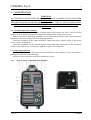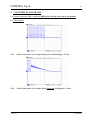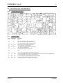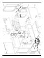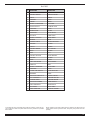
1
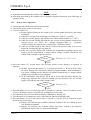
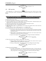
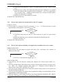
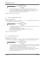
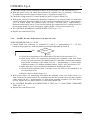
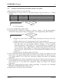
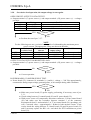
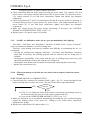
CEBORA S.p.A. 1 TRI STAR MIG 1635/M POWER SOURCE art. 283 SERVICE MANUAL 3.302.233 22/09/2008 CEBORA S.p.A. 2 CONTENTS 1 - GENERAL INFORMATIONS ....................................................................................................................... 3 - Introduction. ................................................................................................................................................. 3 - General service policy. ................................................................................................................................. 3 - Safety informations....................................................................................................................................... 3 - Electromagnetic compatibility...................................................................................................................... 3 2 - SYSTEM DESCRIPTION .............................................................................................................................. 4 2.1 - Introduction. ................................................................................................................................................. 4 2.2 - Technical specifications................................................................................................................................ 4 2.3 - Description of power source art. 283............................................................................................................ 4 3 - MAINTENANCE............................................................................................................................................ 6 3.1 - Periodic inspection, cleaning. ....................................................................................................................... 6 3.2 - Operating sequence....................................................................................................................................... 6 3.2.1 - Power source commands and signaling. .................................................................................................... 6 3.2.2 - Power source operation.............................................................................................................................. 7 3.2.3 - MIG operation. .......................................................................................................................................... 8 3.3 - Troubleshooting............................................................................................................................................ 9 3.3.1 - The power source does not start, control panel off. ................................................................................... 9 3.3.2 - Power source powered, control panel on, fans (27) stopped.................................................................... 10 3.3.3 - Power source powered, display and signals does not indicate the correct values. ................................... 10 3.3.4 - The start button produces no effect.......................................................................................................... 11 3.3.5 - No gas flows from the torch..................................................................................................................... 11 3.3.6 - In MIG, the wire feeder motor (31) does not work.................................................................................. 12 3.3.7 - In open circuit operation, the output voltage is not regular. .................................................................... 13 3.3.8 - In resistive load operation, the output voltage is not regular. .................................................................. 14 3.3.9 - In MIG, arc difficult to strike, the arc goes out immediately after lighting. ............................................ 15 3.3.10 - When start button is released, the wire sticks to the workpiece (ineffective motor braking)................... 15 3.4 - Error codes and alarm signals..................................................................................................................... 16 3.4.1 - 02 - EEPROM error. ................................................................................................................................ 16 3.4.2 - 10 - Malfunction in the circuit to detect short-circuits at the output........................................................ 16 3.4.3 - 42 - Wire feeder motor (31) fault............................................................................................................. 16 3.4.4 - 52 - “trG” on display (M). Start button pressed during start-up............................................................... 16 3.4.5 - 53 - “trG” on display (M). Start button pressed while resetting from stop due to temperature beyond allowable limits. ......................................................................................................................................... 16 3.4.6 - 54 - Short-circuit between torch and workpiece upon start-up. ............................................................... 17 3.4.7 - 56 - Short-circuit at the output lasts too long (max. allowable time = 1 sec.).......................................... 17 3.4.8 - 57 - Wire feeder motor (31) current too high........................................................................................... 17 3.4.9 - 61 - Mains voltage lower than minimum limit......................................................................................... 18 3.4.10 - 62 - Mains voltage higher than maximum limit....................................................................................... 18 3.4.11 - 73 - “tH” on display (M), “0” on display (N) = output diode temperature excessive. ............................. 18 3.4.12 - 99 - “OFF” on display (M). Incorrect mains voltage (machine shut off)................................................. 18 4 - COMPONENTS LIST................................................................................................................................... 19 4.1 - Power source art. 283 : see file ESP283.pdf enclosed at the end of the manual......................................... 19 4.2 - Components table: see file ESP283.pdf enclosed at the end of the manual................................................ 19 4.3 - Spare parts list. ........................................................................................................................................... 19 5 - ELECTRICAL DIAGRAMS ........................................................................................................................ 20 5.1 - Power source art. 283 : see file SCHE283.pdf enclosed at the end of the manual...................................... 20 5.2 - Waveforms. ................................................................................................................................................ 20 5.2.1 - Wire feeder motor (31) voltage during correct braking (par. 3.3.10)....................................................... 20 5.2.2 - Wire feeder motor (31) voltage during incorrect braking (par. 3.3.10). .................................................. 20 5.3 - Power board (32), code 5.602.280/B. ......................................................................................................... 21 5.4 - Control board (29), code 5.602.269/A. ....................................................................................................... 22 1.1 1.2 1.3 1.4 3.302.233 22/09/2008 CEBORA S.p.A. 3 1 - GENERAL INFORMATIONS 1.1 - Introduction. The purpose of this manual is to train personnel assigned to carry out maintenance on the power source art. 283 for MIG/MAG, TIG-DC and MMA welding systems. 1.2 - General service policy. It is the responsibility of the customer and/or operator to use the equipment appropriately, in accordance with the instructions in the Instruction Manual, as well as to maintain the equipment and related accessories in good working condition, in compliance with the instructions provided in the Service Manual. Any internal inspection or repairs must be carried out by qualified personnel who are responsible for any intervention on the equipment. It is forbidden to attempt to repair damaged electronic boards or modules; replace them with original Cebora spare parts. 1.3 - Safety informations. The safety notes provided in this manual are an integral part of those given in the Instruction Manual. Therefore, before working on the machine, please read the paragraph on safety instructions in the aforementioned manual. Always disconnect the power cord from the mains, and wait for the internal capacitors to discharge (2 minutes), before accessing the interior of the equipment. Some internal parts, such as terminals and dissipaters, may be connected to mains or otherwise hazardous potentials. It is therefore forbidden to work with the safety guards removed from the machine unless strictly necessary. In this case, take special precautions such as wearing insulating gloves and footwear, and working in a perfectly dry environment with dry clothing. 1.4 - Electromagnetic compatibility. Please read and observe the instructions provided in the paragraph “Electromagnetic compatibility” of the Instruction Manual. 3.302.233 22/09/2008 CEBORA S.p.A. 4 2 - SYSTEM DESCRIPTION 2.1 - Introduction. The TRI STAR MIG 1635/M is a multiprocess system for MIG/MAG, TIG-DC and MMA welding. It is made up of an electronic power source (art. 283) and a set of accessories to adapt to various types of applications (see list in the Sales Catalogue). The power source is controlled by microprocessor circuits, which manage the operative functions of the welding system and operator interface. 2.2 - Technical specifications. To verify the technical specifications, see the machine plate, Instruction Manual, and Sales Catalogue. 2.3 - Description of power source art. 283. Art. 283 is a direct current power source with controlled current, consisting of a single-phase bridge rectifier and a DC/DC converter. Referring to the electrical diagram in par. 5.1, drawing 4.1 and table 4.2, we can identify the main blocks that make up the power source. The main switch (9) powers the power board (32), that is the actual welding current power source, and converts the alternating mains voltage into direct voltage adjusted according to welding needs. It contains all power circuit components: − the power bridge rectifier, equipped with a DC-capacitors pre-charge circuit, which generates the 320 Vdc voltage to power the igbt inverter section; − the DC-capacitors to level this dc voltage; − the igbt inverter, which generates the square-wave alternating voltage for power transformer; − the power transformer, and the TA to detect the current at the primary circuit of the power transformer; − the diode group, made up of two diodes connected to a shared cathode, that rectifies the alternating voltage, generated by the power transformer secondary winding, to make it available at the power source output terminals; − the service transformer for control circuits power supply. The power transformer, powered by the igbt inverter, provides the secondary circuit with voltage and current values suitable for welding. A different winding gives the voltage supply for the wire feeder motor (31) control circuit on control board (29). The TA mounted on the power board (32) provides the control board (29) with the signal of the transformer primary current, for the welding current regulation. The control board (29) contains the main power source microprocessor, and supervises management of the complete power source. In the control board (29) is generated the PWM signal to send to the inverter igbt, and the wire feeder motor voltage supply, with regulation based on the selected welding program requirements. The control board (29), also acts as power source control panel, and contains the following commands and indicators to perform the supervision and management of the complete power source (see Instruction Manual for more informations): − two potentiometers to adjust the output voltage, welding current, and the values assignable to the parameters indicated by displays; − a set of leds to indicate the parameters shown on displays; 3.302.233 22/09/2008 CEBORA S.p.A. 5 − two 3-digit displays to show output voltage, welding current, wire speed, values assignable to the selected parameters, material type, services functions and error codes. The welding current regulation is performed by the microprocessor on the control board (29), based on signals received from the power board (32), and parameters set via control panel. The microprocessor also controls the supply voltage conditions, to activate any safety devices necessary to protect the power source (see Error codes par. 3.4). On the front panel are gathered the terminals for the welding torch, which must be connected according the modalities imposed by the selected welding process (sees Instructions Manual). In particular, are present two GIFAS (G) and (H) terminals for the welding current, a centralized socket (E) with pneumatic socket for the gas, and a two poles connector (F) for the start command from the torch push-button. The choke (28) and the power board (32) diode group outputs, are connected to the power source output terminals, from which is picked up the power source output voltage signal. This signal is used by the control board (29) to detect short-circuits of the wire on the workpiece during welding, and consequently to adjust the welding current, as well as stop the power source if the short-circuit lasts too long. Fans (27), for the power source power elements cooling, are connected to the power board (32) and powered from the same source (+24 Vdc) that feeds the control board (29). The signals processed by the electronic boards and present at their connectors are listed in the table in chapter five of this manual. 3.302.233 22/09/2008 CEBORA S.p.A. 6 3 - MAINTENANCE WARNINGS ANY INTERNAL INSPECTIONS OR REPAIRS MUST BE CARRIED OUT BY QUALIFIED PERSONNEL. BEFORE BEGINNING MAINTENANCE OPERATIONS, UNPLUG THE MACHINE FROM THE MAINS AND WAIT FOR THE INTERNAL CAPACITORS TO DISCHARGE (2 MINUTES). 3.1 - Periodic inspection, cleaning. Periodically open the power source aeration tunnel and remove any dirt or dust to ensure smooth air flow, and thus adequate cooling of the internal parts of the power source. Remove any dirt or metal dust from the wire feed liner and gearmotor unit, also making sure that they are not worn to the point of needing replacement. Check the condition of the output terminals, output and power supply cables of the power source; replace if damaged. Check the condition of the internal power connections and connectors on the electronic boards; if you find “loose” connections, tighten or replace the connectors. 3.2 - Operating sequence. The following sequence represents correct functioning of the machine. It may be used as a guiding procedure for troubleshooting. It must be carried out after each repair without any errors. 3.2.1 - Power source commands and signaling. 3.302.233 22/09/2008 CEBORA S.p.A. 7 NOTE Operations preceded by this symbol refer to operator actions. ♦ Operations preceded by this symbol refer to machine responses that must occur following an operator action. 3.2.2 - Power source operation. System shut off and disconnected from the mains. Connect the power source to the mains. Close the switch (U). ♦ System supplied, lamp on the switch (9) lit, on front panel the display (M) central led flashes. ♦ After three seconds, leds and displays lit (lamp test). Fans (27) working. ♦ After one second, display (M) indicates the Cebora article number (i.e.: “283”). ♦ After one second, display (M) indicates the version of the programs related to the synergic curves (i.e.: “H01”, H = synergic programs table, 01 = programs version); display (N) indicates the version of the “firmware Cebora”. ♦ After one second, displays (M) and (N) indicate the process setup as it was set before the last time the unit was shut off. ♦ After two seconds, display (M) indicates the programmed welding current and display (N) the programmed or actual output voltage (in MIG, indications are related to the synergic program selected). Correct? YES Press the button (V) several times; the selection shown on the displays is repeated in sequence. ♦ In MIG, each time the button (V) is pressed, the leds D, C, B and A lit one after the other; display (M) respectively indicates program number, material thickness, wire speed, welding current; display (N) indicates material type, or output voltage related to the selected synergic program. ♦ In TIG and MMA, only the two led D and A lit one after the other; display (M) temporarily indicates the selected welding process and then the set current; display (N) indicates the output voltage value. Correct? NO (see 3.3.1, 3.3.2, 3.3.3). NO (see 3.3.3). YES Press the button (V) for a time longer than 3 seconds, to enter the “Service Function” menu (“Service Function” menu is related to the welding process selected). Turn the knob (I) to select the desired function, indicated on display (M). Turn the knob (L) to change the value of the function indicated on display (M). Press the button (V) for a time shorter than 3 seconds, to exit the “Service Function” menu and store the current setup. ♦ Display (M) indicates the available functions related to the set welding process (see Instruction Manual). ♦ Display (N) indicates the available choice and values related to the function indicated on display (M) (see Instruction Manual). 3.302.233 22/09/2008 CEBORA S.p.A. 8 Correct? NO (see 3.3.3). YES 3.2.3 - MIG operation. NOTE On continuation it is illustrated the sequence of MIG process only, which involves all the circuits of the power source, and therefore is considerate sufficient for the purpose of this manual. WARNING DURING THE FOLLOWING TESTS DO NOT AIM THE TORCH AT PEOPLE OR PARTS OF THE BODY, BUT ONLY TOWARDS AN OPEN SPACE OR THE WORKPIECE. Switch-off the power source. Connect the gas intake to the fitting (T) on the rear panel. Connect the MIG torch to the central adapter (E), to the (H) positive terminal and the torch signals cable to the connector (F) of the power source. Connect the ground cable to the (G) negative terminal of the power source. Switch-on the power source, closing the switch (U). After the start-up phase, use the button (V) to select the program choice mode (led (D) “PROG” lit). Use the knob (I) to select a MIG program (i.e.: 1 on display (M)). Press and hold down the torch start button for 5 seconds approximately. ♦ Gas begins to flow from the torch, for as long as the button is held down and the pre-gas time selected (the post-gas time is activated only if the power source has delivered current). ♦ Wire begins to feed from the torch, or at least the wire feeder motors starts running, for as long as the button is held down. ♦ Open-circuit output voltage is generated for as long as the button is held down. Correct? YES Move the torch near the workpiece and press the torch button. ♦ Begin welding. Turn the knobs (I) or (L) to attain the current and wire speed conditions suited to the welding to be carried out. ♦ During welding display (M) and (N) indicate the welding current and voltage. Correct? NO (see 3.3.4, 3.3.5) 3.3.6, 3.3.7). NO (see 3.3.8, 3.3.9). YES Release the torch start button. ♦ Arc shuts off immediately, wire stops feeding from the torch, (if a long ramp time and burn-back time are not set), while the gas flow ends after the post-gas period (the post-gas time is activated only if the power source has delivered current). Correct? NO (see 3.3.6, 3.3.10). YES REGULAR OPERATION. 3.302.233 22/09/2008 CEBORA S.p.A. 9 3.3 - Troubleshooting. WARNINGS ANY INTERNAL INSPECTIONS OR REPAIRS MUST BE CARRIED OUT BY QUALIFIED PERSONNEL. BEFORE REMOVING THE PROTECTIVE GUARDS AND ACCESSING INTERNAL PARTS, DISCONNECT THE POWER SOURCE FROM THE MAINS AND WAIT FOR THE INTERNAL CAPACITORS TO DISCHARGE (2 MINUTES). NOTE Items in boldface describe problems that may occur on the machine (symptoms). Operations preceded by this symbol refer to situations the operator must determine (causes). ♦ Operations preceded by this symbol refer to actions the operator must perform in order to solve the problems (solutions). 3.3.1 - The power source does not start, control panel off. MAINS SUITABILITY TEST. No voltage for mains protection. NO Correct? YES ♦ Eliminate any short-circuits on the connections between power cable, switch (9) and power board (32). ♦ Make sure that terminals TP2 and TP3 on power board (32) are not shortcircuited. ♦ Mains not suitable to power the power source (ex.: insufficient installed power). MAINS CONNECTION TEST. Terminals TP2 and TP3 on power board (32) = 230 Vac, with switch (9) closed. YES Correct? NO ♦ Check power cable and plug and replace if necessary. ♦ Check switch (9) and replace if defective. ♦ Check the mains voltage conditions. CONTROL BOARD (29) POWER SUPPLY TEST. Control board (29), connector J7, terminals 3(+) - 4(-) = +13 Vdc for the first 5 seconds approximately (start-up phase); successively +25 Vdc. YES Correct? NO 3.302.233 22/09/2008 CEBORA S.p.A. 10 ♦ Check the wiring between J3 and J7 on control board (29) and J4 power board (32). ♦ With the power source off, temporarily disconnect the connector J7 on control board (29) and check the resistance between terminals 3 - 4 of J7 on control board (29). Corrected value = >Mohm in both measure sense. If short-circuited, replace control (29) and power (32) boards. ♦ Replace power (32) and control (29) boards. ♦ Replace the control board (29). 3.3.2 - Power source powered, control panel on, fans (27) stopped. FANS (27) TEST. Power board (32), connectors J2 and J3, terminals 1(+) - 2(-) = +13 Vdc for the first 5 seconds approximately (start-up phase); successively +25 Vdc. NO Correct? YES ♦ Check the wiring between fans (27) and connectors J2 and J3 on power board (32). ♦ Make sure that there are no mechanical impediments blocking the fans. ♦ Replace the fans (27). ♦ Replace the control board (29). 3.3.3 - Power source powered, display and signals does not indicate the correct values. ERROR CODE TEST. Upon start-up, after the lamp-test, display (M) shows “Err” and display (N) a number, to indicate an error code. NO Correct? YES ♦ See Error codes and alarm signals, par. 3.4. INDICATORS TEST. Upon start-up, after the lamp-test, display (M) indicates the Cebora article number (i.e.: “283”). After one second, display (M) indicates the version of the programs related to synergic curves (i.e.: “H01”, H = synergic programs table (short), 01 = programs version); display (N) indicates the version of the “firmware 283 Cebora”. After one second, displays (M and (N) indicate the process setup as they were set before the last time the unit was shut off. After two seconds, display (M) indicates the programmed welding current and display (N) the programmed or actual output voltage. With the button (V) and knobs (I) and (L) the set-up functions parameters and “Service Functions” adjustments are possible (see Instructions Manual). 3.302.233 22/09/2008 CEBORA S.p.A. 11 YES Correct? NO ♦ Check the wiring between J1 control board (29) and J1 power board (32). ♦ Check the wiring between J3 and J7 control board (29) and J4 power board (32). ♦ Carry out the CONTROL BOARD (29) POWER SUPPLY TEST, par. 3.3.1. ♦ Replace the control (29) and/or power board (32). ♦ Regular operation of the control panel. 3.3.4 - The start button produces no effect. START COMMAND TEST. Control board (29), connector J6, terminals 2(+) – 1(-) = 0 Vdc with torch button pressed (+8 Vdc approximately with button released). YES Correct? NO ♦ Check the wiring between connector J6 control board (29), connector (F) on front panel and the torch button. ♦ Check torch button. If defective, replace. ♦ See CONTROL BOARD (29) POWER SUPPLY TEST, par. 3.3.1. ♦ Replace the control board (29). ♦ Replace the control board (29). 3.3.5 - No gas flows from the torch. SOLENOID VALVE (7) TEST. Solenoid valve (7) terminals = 230 Vac, in MIG or TIG, with torch button pressed (the solenoid valve opening duration also depends on the pre-gas and post-gas parameters set). NO ♦ ♦ ♦ ♦ 3.302.233 Correct? YES Check for gas presence at the power supply fitting (T) on the rear panel, and make sure that the pressure and flow in the intake line comply with the specified values (see specifications in the Instruction Manual). Make sure there are no occlusions in the gas hoses of the power source. With the power source off, check the resistance on solenoid valve (7) terminals = 2500 ohm. If >Mohm (winding broken), replace the solenoid valve (7). Replace the solenoid valve (7). 22/09/2008 CEBORA S.p.A. 12 ♦ Check the wiring between terminals J8 and J9 of power board (32) and solenoid valve (7). ♦ With the power source off, check the resistance on solenoid valve (7) terminals = 2500 ohm. If 0 ohm (short-circuit), replace solenoid valve (7) and power board (32). ♦ Check the wiring between J1 control board (29) and J1 of power board (32). ♦ With power source off, temporarily disconnect connector J1 on control board (29), and make sure the resistance between terminal 5 of the connector disconnected from J1 and terminal 3 of J7 on control board (29) (solenoid valve rele coil). Corrected value = approximately 1 Kohm in both measure senses. If not corrected check the wiring between J7 control board (29) and J4 power board (32) and, if necessary, replace the RL3 rele on power board (32). ♦ See CONTROL BOARD (29) POWER SUPPLY TEST, par. 3.3.1. ♦ Replace the control board (29). 3.3.6 - In MIG, the wire feeder motor (31) does not work. WIRE FEEDER MOTOR (31) TEST. Control board (29), connector J8, terminals 2(+) and 1(-) = approximately +2 / +18 Vdc, based on the program set, with start button pressed and adjustable by knob (I). NO Correct? YES ♦ Check the wiring between J8 control board (29) and wire feeder motor (31). ♦ With power source off, temporarily disconnect the terminals of the wire feeder motor (31) from connector J8 control board (29), and make sure that the resistance between the terminals of the motor left free = approximately 3,5 ohm (motor winding resistance). If >Mohm (winding broken), replace wire feeder motor (31). ♦ Make sure there are no mechanical impediments blocking the motor. ♦ Check the motor rotation sense; if wrong, reverse the wires on the terminals of J8 on control board (29). ♦ Replace the wire feeder motor (31). ♦ With power source off, temporarily disconnect the terminals of the wire feeder motor (31) from connector J8 control board (29), and make sure that the resistance between the terminals of the motor left free = approximately 3,5 ohm (motor winding resistance). If 0 ohm (shortcircuit), replace the wire feeder motor (31) and control board (29). ♦ See CONTROL BOARD (29) POWER SUPPLY TEST, par. 3.3.1 and START COMMAND TEST, par. 3.3.4. ♦ Replace the control board (29). 3.302.233 22/09/2008 CEBORA S.p.A. 3.3.7 13 - In open circuit operation, the output voltage is not regular. OPEN-CIRCUIT OUTPUT VOLTAGE TEST. Output terminal –(G) power source (-) and output terminal +(H) power source (+) = voltages per table: Process Voltage Condition MIG +109 Vdc Start button pressed TIG +95 Vdc Power source powered or start button pressed MMA +109 Vdc Power source powered NO Correct? YES ♦ Correct operation. DC-CAPACITORS PRECHARGE TEST. Power board (32), connector J6, terminals 1(+) and 4(-), voltage = +320 Vdc approximately, constant also during output voltage generation time, as an example during table conditions. YES ♦ ♦ ♦ ♦ Correct? NO ♦ Make sure power board (32) power supply, performing, if necessary, tests of par. 3.3.1. ♦ Check wiring between J1 control board (29) and J1 power board (32). ♦ With power source off, temporarily disconnect connector J1 from control board (29) and make sure the resistance between terminal 3 of the connector disconnected from J1 and terminals 3 of J7 on control board (29) (precharge rele coil). Corrected value = approximately 1 Kohm in both measure senses. If not correct check the wiring between J7 control board (29) and J4 power board (32) and, if necessary, replace the RL1 rele and check the PTC1conditions on power board (32). ♦ Replace power (32) and/or control (29) boards. Check connection between diode group heat sink on power board (32), inductor (28) and power source +(H) output terminal, and between TP9 on power board (32) and power source –(G) output terminal. If you find loose connections, tighten and replace any damaged components. Check wiring between J7 and J3 of control board (29) and J4 of power board (32), between J1 of control board (29) and J1 power board (32), power source +(H) output terminal and J7 of power board (32). If you find loose connections, tighten and replace any damaged components. Make sure control board (29) power supply performing, if necessary, the CONTROL BOARD (29) POWER SUPPLY TEST, par. 3.3.1. Replace power (32) and/or control (29) boards. 3.302.233 22/09/2008 CEBORA S.p.A. 3.3.8 14 - In resistive load operation, the output voltage is not regular. OPEN-CIRCUIT OUTPUT VOLTAGE TEST. Output terminal –(G) power source (-) and output terminal +(H) power source (+) = voltages per table: Process Voltage Condition MIG +109 Vdc Start button pressed TIG +95 Vdc Power source powered or start button pressed MMA +109 Vdc Power source powered YES Correct? NO ♦ Perform the test of par. 3.3.7. NOTE For the following tests use a resistive load capable of withstanding the maximum power source current. The appropriate values are shown in the table. Process Resistor Maximum output Power source Condition resistive load current output voltage MIG 0,14 ohm 160 Adc + 22 Vdc Start button pressed TIG 0,10 ohm 160 Adc + 16,4 Vdc Start button pressed MMA 0,19 ohm 130 Adc + 25,2 Vdc Power source powered OUTPUT VOLTAGE TEST ON RESISTIVE LOAD. Output terminal –(G) power source (-) and output terminal +(H) power source (+) = voltages per table: NO Correct? YES ♦ Correct operation. POWER BOARD (32) POWER SUPPLY TEST. Power board (32), connector J6, terminals 1(+) and 4(-), voltage = +300 Vdc approximately, constant also during output voltage generation time, as an example during table conditions. YES Correct? NO ♦ Make sure power board (32) power supply, performing, if necessary, tests of par. 3.3.1. ♦ Check wiring between J1 control board (29) and J1 power board (32), ♦ With power source off, temporarily disconnect connector J1 from control board (29) and make sure the resistance between terminal 3 of the connector disconnected from J1 and terminals 3 of J7 on control board (29) (precharge rele coil). Corrected value = approximately 1 Kohm in both measure senses. If not correct check the wiring between J7 control board (29) and J4 power board (32) and if necessary replace the RL1 rele and check the PTC1conditions on power board (32). 3.302.233 22/09/2008 CEBORA S.p.A. ♦ ♦ ♦ ♦ 15 ♦ Replace power (32) and/or control (29) boards. Check connection between diode group heat sink on power board (32), inductor (28) and power source +(H) output terminal, and between TP9 on power board (32) and power source –(G) output terminal. If you find loose connections, tighten and replace any damaged components. Check wiring between J7 and J3 of control board (29) and J4 of power board (32), between J1 of control board (29) and J1 power board (32), power source +(H) output terminal and J7 of power board (32). If you find loose connections, tighten and replace any damaged components. Make sure control board (29) power supply performing, if necessary, the CONTROL BOARD (29) POWER SUPPLY TEST, of par. 3.3.1. Replace power (32) and/or control (29) boards. 3.3.9 - In MIG, arc difficult to strike, the arc goes out immediately after lighting. “Hot-Start”, “Soft Start” and “Impedance” functions, available in the “Service Functions” menu (see Instruction Manual), can assist welding start. Therefore, when dealing with start-up problems and difficulty in maintaining the arc, we recommend: − Carrying out welding tests, changing “Hot-Start”, “Soft Start” and “Impedance” functions values and, if necessary, the working program with one similar to the one being used, if available. − Checking the compatibility of the torch with the type of welding being carried out, and especially matching the torch nozzle with the wire being used. − Checking the wear status of the torch and its components, replacing them if necessary. − Replace the control board (29). 3.3.10 - When start button is released, the wire sticks to the workpiece (ineffective motor braking). WIRE FEEDER MOTOR (31) BRAKING TEST. Control board (29), connector J8, terminals 2 and 1 (gnd) = fig. 5.2.1, upon releasing the start button and with open-circuit power source. The wire feeder motor stops immediately. YES Correct? NO ♦ If fig. 5.2.2 is found (the motor slows from its own inertia), the braking circuit on the control board (29) does not work, replace control board (29). ♦ Carry out the WIRE FEEDER MOTOR (31) TEST, par. 3.3.6. ♦ Make sure that there are no mechanical impediments preventing the wire coil from stopping despite the braking action of the motor (ex.: sliding by wire feeder rollers, improperly adjusted roller spring). ♦ Replace the control board (29) and/or motor (31). 3.302.233 22/09/2008 CEBORA S.p.A. 16 3.4 - Error codes and alarm signals. 3.4.1 - 02 - EEPROM error. Block due to software error. Replace the control board (29). 3.4.2 - 10 - Malfunction in the circuit to detect short-circuits at the output. Upon power source start-up this test checks the operating conditions by performing a brief test to generate the open-circuit output voltage. While this is taking place it is important that the torch not touch the workpiece or welding bench. The following conditions may be detected during this test: − Output voltage present and output current present = error 54; − Output voltage present and output current absent = correct operation; − Output voltage absent and output current present = error 54; − Output voltage absent and output current absent = error 10. Error 10 indicates that a low output voltage (<45 Vdc) has been detected, with no output current from the power source. This test is carried out only during the power source start-up. This may be caused by an interruption in the inverter command circuits, or in the power circuits, or in the output voltage detection line. Check the wiring between power source +(H) output terminal and terminal J7 of power board (32) and wiring between terminals 9(+) and 10(-) of J1 control board (29) and terminals 9(+) and 10(-) of J1 power board (32). In case of “Error 10” carry out the open circuit operation test in par. 3.3.7. If results are positive, replace control board (29). 3.4.3 - 42 - Wire feeder motor (31) fault. This signal indicates a failure in the wire feeder motor (31) supply circuit. In particular, motor supply voltage is generated but no motor current absorption is detected (open circuit). See WIRE FEEDER MOTOR (31) TEST, par. 3.3.6. 3.4.4 - 52 - “trG” on display (M). Start button pressed during start-up. See START COMMAND TEST, par. 3.3.4. 3.4.5 - 53 - “trG” on display (M). Start button pressed while resetting from stop due to temperature beyond allowable limits. The high temperature alarm stops the power source with indication “tH0” on display (M), but it doesn’t remain in memory. It is automatically reset when the temperature falls within the allowed limits. It may occur that the unit resets when the start command is present; therefore, to prevent the power source from starting suddenly, due to a random reset, this situation is detected and causes a stored block in the power source, with “trG” indication on display (M). To restore proper functioning, remove the start command, and if necessary carry out the START COMMAND TEST, par. 3.3.4. 3.302.233 22/09/2008 CEBORA S.p.A. 17 3.4.6 - 54 - Short-circuit between torch and workpiece upon start-up. Upon power source start-up this test checks the operating conditions by performing a brief test to generate the open-circuit output voltage. While this is taking place it is important that the torch not touch the workpiece or welding bench. The following conditions may be detected during this test: − Output voltage present and output current present = error 54; − Output voltage present and output current absent = correct operation; − Output voltage absent and output current present = error 54; − Output voltage absent and output current absent = error 10. Error 54 indicates a possible short-circuit or isolation leak in the power circuit downstream of the diode group or at power board (32) output. Check the wiring between power source +(H) output terminal and terminal J7 of power board (32) and wiring between terminals 9(+) and 10(-) of J1 control board (29) and terminals 9(+) and 10(-) of J1 power board (32). Check inductor (28) integrity and correct connection. If you find defective connections, fix and replace any damaged components. Replace the control (29) and/or power (32) boards. 3.4.7 - 56 - Short-circuit at the output lasts too long (max. allowable time = 1 sec.). It is normal to detect short-circuits at the output during welding, as long as they do not last beyond a given interval. “Error 56” indicates that the short-circuit has exceeded this limit. This situation can be determined also from the short circuit created between wire nozzle and gas nozzle on the MIG torch, because of the warehouse of dirt or metallic powder. In MMA it can derive also from the output voltage detection line interruption. In any case, beyond to the torch cleaning, to check: − connection between power source + output terminal and terminal J7 of power board (32); − wiring between terminals 9(+) and 10(-) of J1 control board (29) and terminals 9(+) and 10(-) of J1 power board (32); − integrity and corrected connection of inductor (28). If you find defective connections, fix and replace any damaged components. Replace the control (29) and/or power (32) boards. 3.4.8 - 57 - Wire feeder motor (31) current too high. The control board (29) is equipped with a motor (31) feeding current limitation circuit, to protect it against eventual overloads, and with a circuit that reveals when the participation of the limiter is uninterrupted, in order to evidence an extended overload. Such overload is determined mostly from mechanical causes, which dirt in the gears of the gearbox, hardness’s from lubrication lack, wire coil dragging difficulty, throttling in the wire sheath long the cable torch, etc. Therefore carry out the motor gear box group cleaning, and check if in the no wire operation the problem is still present. In this case the deterioration of the motor winding or the mechanically connected gear box can be assumed, for which replacing motor (31) or mechanical gear box. If necessary, carry out the WIRE FEEDER MOTOR (31) TEST, par. 3.3.6. 3.302.233 22/09/2008 CEBORA S.p.A. 18 3.4.9 - 61 - Mains voltage lower than minimum limit. 3.4.10 - 62 - Mains voltage higher than maximum limit. The control board (29) verifies the mains voltage by means the +24 Vdc supply voltage check. If the mains voltage results suitable, the power source gets ready for the operation; if instead it is judged too low, the control commands the block for error 61, if too high commands the block for error 62. Check the wiring between J4 of power board (32) and J7 of control board (29) and, if necessary, carry out the tests of par. 3.3.1, or replace power (32) and/or control (29) boards. 3.4.11 - 73 - “tH” on display (M), “0” on display (N) = output diode temperature excessive. With this alarm we recommend do not shut off the power source, to keep the fans running and thus allow rapid cooling. Normal operation is restored automatically as soon as the temperature returns within the allowed limits. If the alarm occurs repeatedly, we recommend that you: − Make sure that air flows smoothly, and there is no dust or other impediments to cooling in the aeration tunnels. − Check the fans (27) supply voltage, on J2 and J3 of power board (32), terminals 1(+) and 2(-) = +25 Vdc. If not correct, replace power board (32). If correct, verify fans (27) correct operation and if defective replace them. − Make sure that the working conditions comply with the specified values, especially observing the “duty cycle”. − Make sure the diode holding screws on the dissipater on the power board (32), are firmly tightened. − Make sure correct assembly and operation of the temperature sensor, mounted on the output diode dissipater on power board (32); with ambient temperature, on the inductors L3(+) and L2(-), on control board (29), must be measured a voltage of approximately +3 Vdc. If correct, replace control board (29). If not correct, check the wiring between terminals 6 and 7 of J1 power board (32) and terminals 6 and 7 of J1 control board (29) (temperature control line) and, if necessary, replace the temperature sensor on power board (32) or the power board (32) complete. − Replace the control (29) and/or power (32) boards. 3.4.12 - 99 - “OFF” on display (M). Incorrect mains voltage (machine shut off). This signal normally appears whenever the power source is shut off. When mains voltage is missing, for example after opening the switch (9), the control circuit remains powered for a few seconds due to the effects of the DC-capacitor discharge on the supply circuits and finding a supply voltage fast lowering, it commands the power source stop, with “OFF” signaling. This alarm is similar to error 61, which, being filtered, results more efficient on supply voltage slow lowering. If this signal is present with switch (9) closed and mains voltage present, carry out the MAINS CONNECTION TEST and CONTROL BOARD (29) POWER SUPPLY TEST of par. 3.3.1. 3.302.233 22/09/2008 CEBORA S.p.A. 4 19 - COMPONENTS LIST 4.1 - Power source art. 283 : see file ESP283.pdf enclosed at the end of the manual. 4.2 - Components table: see file ESP283.pdf enclosed at the end of the manual. 4.3 - Spare parts list. Essential spare parts. Ref. Code 29 32 5602282 5602280 Description control board power board Qty. 1 1 Recommended spare parts. Ref. Code 7 9 27 31 35 3160179 3190014 5710532 5710358 1275.00 3.302.233 Description solenoid valve switch fan motor reducer torch complete Qty. 1 1 1 1 1 22/09/2008 CEBORA S.p.A. 20 5 - ELECTRICAL DIAGRAMS 5.1 - Power source art. 283 : see file SCHE283.pdf enclosed at the end of the manual. 5.2 - Waveforms. 5.2.1 - Wire feeder motor (31) voltage during correct braking (par. 3.3.10). 5.2.2 - Wire feeder motor (31) voltage during incorrect braking (par. 3.3.10). 3.302.233 22/09/2008 CEBORA S.p.A. 21 5.3 - Power board (32), code 5.602.280/B. 5.3.1 - Topographical drawing. 5.3.2 Conn. J1 J1 J1 J1 J1 J1 J1 J2 J3 J4 - Connector table. Terminals Function 1-2 NU. 3 RL1 rele command input (precharge 1). 4 RL2 rele command input (precharge 2). 5 RL3 rele command input (solenoid valve). 6(+) - 7(-) temperature sensor analog signal output. 8 +14 Vdc supply voltage input. 9(+) - 10(-) “power source output voltage” signal output. 1(+) - 2(-) +24 Vdc fan (27) command output. 1(+) - 2(-) +24 Vdc fan (27) command output. 1(+) - 2(-) +35 Vdc approximately output, for wire feeder motor (31) control circuit voltage supply (only present with power source output voltage). J4 3(+) - 4(-) PWM signal input, for igbt driver. J4 5(+) - 10(-) primary current feedback signal output, from TA. J4 6(+) - 7(-) +35 Vdc approximately output, for wire feeder motor (31) control circuit voltage supply (only present with power source output voltage). J4 9(+) - 8(-) +24 Vdc control board (29) supply voltage output. J5 2(+) - 1(-) NU. (+35 Vdc approximately output, for wire feeder motor (31) control circuit voltage supply (only present with power source output voltage). J6 1(+) - 4(-) NU. (+320 Vdc approximately, inverter power supply voltage). J7 power source output voltage input (positive potential). J8-J9 solenoid valve (7) command output. TP2 - TP3 230 Vac power board (32) voltage supply input. TP1 GND. TP9 power board (32) output voltage output (negative potential). 3.302.233 22/09/2008 CEBORA S.p.A. 22 5.4 - Control board (29), code 5.602.269/A. 5.4.1 - Topographical drawing. 5.4.2 - Connector table. Conn. J1 J1 J1 J1 J1 J1 J1 J2 J3 J4 J5 J6 J7 Terminals 1-2 3 4 5 6(+) - 7(-) 8 9(+) - 10(-) 1(+) - 2(-) 1-2 1(+) - 2(-) J7 J7 J8 3(+) - 4(-) 5(+) - 6(-) 2(+) - 1(-) 3.302.233 Function NU. RL1 rele command output (precharge 1). RL2 rele command output (precharge 2). RL3 rele command output (solenoid valve). temperature sensor analog signal input. +14 Vdc supply voltage output. “power source output voltage” signal input. NU. (board programming). PWM signal output, for igbt driver. NU. NU. power source start signal input, from torch button. +35 Vdc approximately input, for wire feeder motor (31) control circuit voltage supply (only present with power source output voltage). +24 Vdc input, for control board (29) supply voltage. primary current feedback signal input, from TA. wire feeder motor (31) voltage supply output. 22/09/2008 Art. 283 14 Art. 283 pos DESCRIZIONE DESCRIPTION 01 LATERALE FISSO FIXED SIDE PANEL 02 SUPPORTO MANICO HANDLE SUPPORT 03 MANICO HANDLE 04 COPERCHIO COVER 05 CORNICE FRAME 06 PANNELLO POSTERIORE BACK PANEL 07 ELETTROVALVOLA SOLENOID VALVE 08 COPERTURA COVER 09 INTERRUTTORE SWITCH 10 PRESSACAVO STRAIN RELIEF 11 CAVO RETE POWER CORD 12 PANNELLO ALETTATO FINNED PANEL 13 CERNIERA HINGE 14 LATERALE MOBILE HINGED SIDE PANEL 15 CHIUSURA CLOSING 16 ROSETTA WASHER 17 SUPPORTO BOBINA COIL SUPPORT 18 FONDO BOTTOM 19 PIEDE FOOT 20 SUPPORTO MOTORE MOTOR BRACKET 21 CHIUSURA CLOSING 22 PRESA SOCKET 23 CORPO ADATTATORE ADAPTOR BODY 24 MANOPOLA KNOB 25 PANNELLO ANTERIORE FRONT PANEL 26 COPERTURA COVER 27 MOTORE CON VENTOLA MOTOR WITH FAN 28 IMPEDENZA CHOKE 29 CIRCUITO DI CONTROLLO CONTROL CIRCUIT 30 RULLO TRAINAFILO WIRE FEED ROLLER 31 MOTORIDUTTORE WIRE FEED MOTOR 32 CIRCUITO DI POTENZA POWER CIRCUIT 33 PIANO INTERMEDIO INSIDE BAFFLE 34 CAVO MASSA EARTH CABLE 35 TORCIA COMPLETA COMPLETE TORCHE La richiesta di pezzi di ricambio deve indicare sempre: numero di articolo, matricola e data di acquisto della macchina, posizione e quantità del ricambio. When ordering spare parts please always state the machine item and serial number and its purchase data, the spare part position and the quantity. 15