1
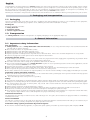
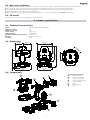
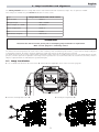
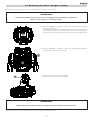
instructions manual
manuale di istruzioni
Version 1.0
DIS91/1
∞ Infinity Wash XL
numero di serie/serial number
data di acquisto/date of purchase
fornitore/retailer
indirizzo/address
cap/città/suburb
provincia/capital city
stato/state
tel./fax/
Prendete nota, nello spazio apposito, dei dati relativi al modello e al rivenditore del vostro Infinity Wash XL: ci
permetteranno di assistervi con la massima rapidità e precisione.
Please note in the space provided above the relative service information of the model and the retailer from
whom you purchased your Infinity Wash XL: This information will assist us in answering any technical
enquiries with the utmost speed and accuracy.
ATTENZIONE: la sicurezza dell’apparecchio è garantita solo con l’uso appropriato delle presenti istruzioni, pertanto è necessario conservarle.
WARNING: the security of the fixture is granted only if these instructions are strictly followed; therefore it is
absolutely necessary to keep this manual.
Users Manual Version 1.0
edition December 2007
English
Index
1. Packaging and transportation
Pag. 6
1.1. Packaging
1.2. Transportation
“
“
2. General information
6
6
Pag. 6
2.1. Important safety information
2.2. Warranty conditions
2.3. CE norms
“
“
“
3. Product specifications
6
7
7
Pag. 7
3.1. Technical characteristics
3.2. Dimensions
3.3. Projector components
“
“
“
4. Installation
7
7
7
Pag. 8
4.1. Mechanical installation
4.2. Safety connections
“
“
5. Powering up
8
8
Pag. 9
5.1. Operating voltage and frequency
5.2. Altering the operating voltage and frequency
5.3. Mains connection
“
“
“
9
9
10
6. DMX signal connection
Pag. 11
7. Turning on the projector
Pag. 12
7.1. DMX addressing
7.2. DMX functions
“
“
8. Display panel functions
8.1.
8.2.
8.3.
8.4.
8.5.
8.6.
8.7.
12
13
Pag. 15
Quick guide to menu navigation
Rapid scrolling
Main functions
Measures
Display setup
Demo mode
Special mode and motors electronic alignment
9. Lamp installation and alignment
“
“
“
“
“
“
“
15
15
16
18
19
19
20
Pag. 21
9.1. Lamp installation
9.2. Aligning the lamp in the optical path
“
“
21
22
10. Removing the colour changer assembly
Pag. 21
11. Maintenance
Pag. 23
11.1.
11.2.
11.3.
11.4.
Periodic cleaning
Periodic maintenance
Fuse replacement
Electronic motor alignment
“
“
“
“
24
24
24
24
12. Spare parts
Pag. 24
13. Error messages
Pag. 25
14. Frequently asked questions
Pag. 26
5
English
Congratulations on having purchased a Coemar product. You have assured yourself of a fixture of the highest quality, both in componentry and in the technology used. We renew our invitation to you to complete the service information on the previous page, to expedite any request for service information or spares (in case of problems encountered either during, or subsequent to, installation). This
information will assist in providing prompt and accurate advice from your Coemar service centre.
Following the instructions and procedures outlined in this manual will ensure the maximum efficiency of this product for years to come.
1. Packaging and transportation
1.1. Packaging
Open the packaging and ensure that no part of the equipment has suffered damage in transit. In case of damage to the equipment,
contact your carrier immediately by telephone or fax, following this with formal notification in writing.
Packing list
Ensure the packaging contains:
1 Infinity Wash XL
1 instruction manual
2 cam-lock support brackets
1.2. Transportation
The Infinity Wash XL should be transported in its original packaging or in an appropriate flight case.
2. General information
2.1. Important safety information
Fire prevention:
1. Infinity Wash XL utilises a Philips MSR GOLD 1200 SA/SE FastFit; the use of any alternative lamp is not recommended and will
null and void the fixture’s warranty.
2. Never locate the fixture on any flammable surface.
3. Minimum distance from flammable materials: 0,5 m.
4. Minimum distance from the closest illuminable surface: 2 m.
5. Replace any blown or damaged fuses only with those of identical values. Refer to the schematic diagram if there is any doubt.
6. Connect the projector to mains power via a thermal magnetic circuit breaker.
Preventing electric shock:
1. High voltage is present in the internals of the unit. Isolate the projector from mains supply prior to performing any function which
involves touching the internals of the unit, including lamp replacement.
2. For mains connection, adhere strictly to the guidelines outlined in this manual.
3. The level of technology inherent in the Infinity Wash XL requires the use of specialised personnel for all service applications; refer all
work to your authorised Coemar service centre.
4. A good earth connection is essential for proper functioning of the projector.
5. Mains cables should not come into contact with other cables. Never operate the unit without proper earth connection.
6. Do not operate the projector with wet hands or in an area where water present.
7. The fixture should never be located in an exposed position, or in areas of extreme humidity. A steady supply of circulating air is essential.
Protection against ultraviolet radiation:
1. Never turn on the lamp if any of the lenses, filters, or the carbon fibre housing is damaged; their respective functions will only operate
efficiently if they are in perfect working order.
2. Never look directly into the lamp when it is operating.
Safety:
1. The projector should always be installed with bolts, clamps, and other fixings which are suitably rated to support the weight of the unit.
2. Always use a secondary safety chain of a suitable rating to sustain the weight of the unit in case of the failure of the primary fixing point.
3. The external surface of the unit, at various points, may exceed 150°C. Never handle the unit until at least 10 minutes have elapsed
since the lamp was turned off.
4. Always replace the lamp if any physical damage is evident.
5. Never install the fixture in an enclosed area lacking sufficient air flow; the ambient temperature should not exceed 35°C.
6. Wait at least 10 minutes after the unit has been turned off prior to attempting to replace the lamp.
7. The proejctor contains electronic and electrical components which should under no circumstances be exposed to contact with water,
oil or any other liquid. Failure to do so will compromise the proper functioning of the projector.
Articulated movement
The projector has a pan range of 540° in its base and a tilt range 262° in its yoke; do not obstruct the projector whilst it is undertaking
articulated movement.
Forced ventilation
You will note several air vents on the body of the projector. To avoid any problems associated with overheating, never obstruct any of
these vents as this may seriously compromise the proper operation of the unit.
Protection rating against penetration by external agents:
1. The fixture is classified ordinary apparatus ; its protection grade against penetration by external agents,solid or liquid, is IP 20.
6
English
2.2. Warranty conditions
1. The fixture is guaranteed for a period of 12 months from the date of purchase against manufacturing or materials defects.
2. The warranty does not extend to damage caused by inappropriate usage or use by inexperienced operators.
3. The warranty is immediately void if the projector has been operated or dismantled by unauthorised personnel.
4. The warranty does not extend to fixture replacement.
5. The serial number of the projector is required for any advice or service fro your authorised Coemar service centre.
2.3. CE norms
The projector meets or exceeds all applicable CE requirements.
3. Product specifications
3.1. Technical characteristics
Power:
Nominal current:
Maximum current:
Power factor:
Lamp wattage:
Maximum ambient temperature:
Weight:
IP rating:
200/208/230/240 Vac 50/60Hz
8A
10A
cos ϕ = 0,9
1200W MH
35°C / 95° F
45.5 Kg / 100.1 Lbs
IP20
3.2. Dimensions
269.6mm
10.61”
292mm
11.50”
535.4mm
21.08”
304.8mm
12”
801.5mm
31.55”
163.4mm
6.43”
492.6mm
19.39”
591.6mm
22.11”
m
8m
4. 2”
30 1
30mm
1.18”
304.8mm
12”
509.7mm
20.07”
580.7mm
22.86”
3.3. Components
A
Component description
A.
Body housing
B.
Zoom effect group
C.
Color wheel group
D.
Colors changer group
E.
Reflector group
F.
Yoke
G.
Base housing
H.
Base
E
D
C
B
F
G
H
7
English
4. Installation
4.1. Mechanical installation
Infinity Wash XL may be either floor or ceiling mounted. For floor mounting, the unit is provided with four rubber mounting feet.
For ceiling mounted installations, Coemar includes two cam-lock (A) support brackets.
The two cam-lock brackets may be mounted in 3 different positions (B, C and D) on the base of the Infinity Wash XL. The cam-lock
brackets are affixed via a 1/4 nut. Please ensure that they are correctly seated and firmly tightened into position.
B
C
D
m
8m
4. 2”
30 1
304.8mm
12”
A
304.8mm
12”
For ceiling mounted installations we suggest the use of appropriate clamps or fixings to attach the fixture to the mounting surface. Clamps
may be attached to the central hole provided in the cam-lock brackets, as shown in the following diagram.
ATTENTION!!
Ensure that the structure from which the unit is hung is of sufficient rating to hold the weight of the unit,
as are any clamps, nuts and bolts used to hang the unit.
The structure from which the unit is hung should be of sufficient rating to hold the weight of the unit, as should any clamps used to hang
the unit. The structure should also be sufficiently rigid so as not to move or shake whilst the projector moves during its operation.
Do not install the projector in locations where it is readily accessible by aunthorised or untrained personnel.
4.2. Safety connections
If the Infinity Wash XL is affixed to a structure the use of a safety chain designed to meet relevant safety standards is recommended. You
may attach the safety chain to the holes “E” located on the base of the fixture and to the structure itself.
If using an after-market safety chain not manufactured by Coemar, ensure that it is of sufficient rating to hold the weight of the unit.
E
8
English
5. Powering up
5.1. Operating voltage and frequency
The projector may operate at voltages of 200, 208, 230 or 240VAC at a frequency of 50 or 60Hz. Coemar presets (barring specific
requests) a voltage of 230v at a frequency of 50Hz.. The preset voltage is indicated on the base of the projector.
Infinity Wash XL will automatically adjust its operation to suit a frequency of 50Hz or 60Hz.
5.2. Altering the operating voltage (Reserved for technical personnel only)
If the factory preset operating voltage do not correspond to those in use in your country of operation, you may alter the settings as described in the following paragraphs.
ATTENTION!!
Incorrect selection of operating voltage will seriously compromise the
functioning of the projector and will immediately void the warranty.
1. Loosen the screws “A” on the cover of the base of the unit, as shown in
the diagram below, using an appropriate screwdriver, thereby removing
the cover completely and allowing access to the internal components of
the base of the Infinity Wash XL.
2. Locate the main selector in the base of the unit.
3. Select a voltage from amongst 200, 208, 230 or 240V by moving the
selector to the correct voltage.
4. When you have made changes, note these on the outside of the
Infinity Wash XL.
5. Replace and fasten all the housings as per their original positions.
9
English
5.3. Mains connection
Mains cable characteristics
The mains cable provided is thermally resistant, complying to the most recent international standards. It meets or exceeds VDE and IEC norms, IEC
331,IEC 332 3C,CEI 20 35.
NB: In case of cable replacement, similar cable with comparable thermal resistant qualities must be used exclusively (cable 3x1.5 ø external
10 mm, rated 300/500V, tested to 2KV, operating temperature -40° +180°, Coemar cod. CV5309).
Connecting to mains power
For connection purposes, ensure your plug is of a suitable rating to sustain the maximum current:
•200/208/230/240Vac
4.5 amps constant current in normal operation
Locate the mains cable which exits the base of the unit and connect as shown below:
brown
live
blue
neutral
yellow/green
ground
main
ATTENTION!!
• The use of a thermal magnetic circuit breaker is recommended for each projector. Strict adherance to all regulatory
norms is higly recommended.
• Infinity Wash XL should never be supplied mains power via a Dimmer; this is potentially dangerous.
• Prior to powering up the projector, ensure that the model in your possession correctly mathces the mains supply available to you.
• A good earth connection is essential for the correct operation of the Infinity Wash XL. Never connect the projector to
main power if the green/yellow earth cable is not correctly connected
• All cable and plug connections should be carried out by fully qualified and licenced personnel only.
10
English
6. DMX signal connection
Control signal is digital and is transmitted via two pair screened ø0.5mm cable as per international standards for the transmission of
DMX512 data. Connection is serial, utilising XLR3 and XLR5, male and female sockets located on the base of the Infinity Wash XL, labeled DMX 512 IN and OUT (see diagram).
Plug/socket connections for XLR3 and XLR5 connectors:
Pin connections conform to the international standard as per the following table:
pin 1 = GND
pin 2 = data pin 3 = data +
If using a controller which output signal via an XLR 5 (5 pin) socket, do not use pins 4 and 5, leave them unconnected.
in
out
in
out
Controller
Standard
DMX 512
OUT
3
2
1
Ad altri Infinty Wash XL
Connect to other Infinty Wash XL
ATTENTION!!
Ensure that all data conductors are isolated from one another and the metal housing of the connector.
Pin number 1 should never be connected to the device’s power supply.
11
English
7. Turning on the projector
After having followed the preceding steps, turn on the projector via the main Power switch.
The display will show in sequence the software version installed on the onboard microprocessors .
For example, upon turning on power, the Infinity Wash XL may show:
Software version currently installed on
the electronic boards of the fixture
The projector will perform a reset function on all the internal and external motors. This will last only few seconds, after which it will be
subject to the external signal from the controller. The display will remain fixed indicating the correct DMX 512 signal reception.
If the display is flashing, there is no DMX signal being received. Check your cabling and your controller.
During the reset the display will blink
for few seconds...
...then the DMX address of the fixture
will appear.
7.1. DMX addressing
Each projector utilises 22 channels of DMX 512 for complete control (for further information, see section 7.2. DMX functions).
DMX addresses
To ensure that each projector accesses the correct signal, it is necessary to correctly address each fixture. This procedure must be carried
out on every projector being used. When powered up initially, each projector will show A001 which indicates DMX address 001; a
projector thus addressed will respond to commands on channel 1 to 22 from your DMX controller. A second unit should be addressed
as A023, a third as A045 and so on until the final projector has been addressed.
Altering DMX addresses
1. Press the + or - buttons until the display shows the required DMX address. The characters in the display will flash to indicate that the
selection is not yet stored in memory.
2. Press the enter button to confirm your selection. The display panel will cease to flash and the projector will now respond to the new
DMX 512 address.
DMX ADDRESS
A001
e n ter
+
en
t er
enu
+
m
m
enu
Important Note: holding down the + or - buttons will cause the display to alter at an increased speed, allowing a faster selection to be made.
ATTENTION!!
If you alter the DMX with no DMX controller connected, the characters in the display panel will continue to flash
even after you have pressed the ENTER button.
12
English
7.2. DMX functions
dmx
channel
function
type of control
1
X axis, base movement
(pan) coarse
proportional
2
X axis, base movement
(pan) fine
3
4
5
decimal
percentage
proportional coarse control of the base motor movement
0
- 255
0% - 100%
proportional
proportional fine control of the base motor movement
0
- 255
0% - 100%
Y axis, yoke movement
(tilt) coarse
proportional
proportional coarse control of the yoke motor movement
0
- 255
0% - 100%
Y axis, yoke movement
(tilt) fine
proportional
proportional fine control of the yoke motor movement
0
- 255
0% - 100%
-
0% -
movement speed
step
standard (fast)
0
step
ultra fast movement (best for programming positions)
10 - 25
dimmer
26 - 127
10% - 50%
proportional
tracking mode (from fast to slow)
128 - 247
50% - 97%
tracking mode (slow)
248 - 255
97% - 100%
proportional
step
step
proportional
shutter, strobe
and zap effect
4%
4% - 10%
vector mode (from fast to slow)
proportional
7
9
proportional
step
6
effect
step
proportional
step
proportional
step
gradual adjustment of luminous intensity from 0 to 100%
0
- 255
shutter closed (zap off)
0
-
strobe effect with variable speed from slow to fast
10 - 66
9
0% - 100%
0% -
4%
4% - 26%
shutter open (zap off)
67 - 68
26% - 27%
sequenced pulse effect, slow closing, fast opening (with variable speed from slow to fast)
69 - 125
27% - 49%
shutter open (zap off)
126 - 127
49% - 50%
sequenced pulse effect, fast closing, slow opening (with variable speed from fast to slow)
128 - 184
50% - 72%
shutter open (zap off)
185 - 187
73% - 73%
random strobe effect, non-synchronised, variable speed from slow to fast
188 - 244
74% - 96%
shutter open (zap off)
245 - 255
96% - 100%
8
zoom effect
proportional
proportional control of zoom effect wheel from narrow to wide beam (from 6° to 13°)
0
- 255
0% - 100%
9
zoom
proportional
proportional control of zoom from narrow to wide beam (from 6° to 80°)
0
- 255
0% - 100%
-
step
10
zoom shake
no effect
0
proportional
zoom shake effect with variable speed from slow to fast
10 - 71
4% - 28%
proportional
zoom shake sequenced pulse effect, slow closing, fast opening
(with variable speed from slow to fast)
72 - 133
28% - 52%
proportional
zoom shake sequenced pulse effect, fast closing, slow opening
(with variable speed from fast to slow)
134 - 195
53% - 76%
proportional
zoom shake random strobe effect, non-synchronised, variable speed from slow to fast
196 - 255
77% - 100%
step
11
selecting effects wheel
+
shake movement
-
9
9
0% -
0% -
4%
no effect
0
effect 1
10 - 39
4% - 15%
4%
effect 2
40 - 69
16% - 27%
effect 3
70 - 99
27% - 39%
effect 4
100 - 128
39% - 50%
shake effect 4 (variable adjustment of oscillation angle from minimum to maximum)
129 - 160
51% - 63%
shake effect 3 (variable adjustment of oscillation angle from minimum to maximum)
161 - 192
63% - 75%
shake effect 2 (variable adjustment of oscillation angle from minimum to maximum)
193 - 224
76% - 88%
shake effect 1 (variable adjustment of oscillation angle from minimum to maximum)
225 - 255
88% - 100%
proportional
step
12
indexing effect rotation
through 360°
no effect
0
proportional
proportional indexing of the effect through 360°
10 - 128
4% - 50%
proportional
continuous rotation of the effect in a counter-clockwise direction with
proportional control over decreasing speed
129 - 188
51% - 74%
stop effect rotation
189 - 193
74% - 76%
continuous rotation of the effect in a clockwise direction with
proportional control over increasing speed
194 - 255
76% - 100%
step
proportional
13
-
9
0% -
4%
English
dmx
channel
function
type of control
effect
decimal
percentage
no colour, white beam
0
-
5
0% -
color 1
6
- 14
2% -
5%
color 2
15 - 22
6% -
9%
color 3
23 - 30
9% - 12%
color 4
31 - 38
12% - 15%
color 5
39 - 45
15% - 18%
from color 5 to colour 1, proportional positioning
46 - 127
18% - 50%
rainbow effect from fast to slow in an anticlockwise direction
128 - 190
50% - 75%
rainbow effect from slow to fast in a clockwise direction
191 - 255
75% - 100%
2%
step
13
selecting colors from the color
wheel
proportional
14
cyan
proportional
proportional control of the percentage of cyan color in the light beam from 0 to 100%
0
- 255
0% - 100%
15
cyan color saturation
proportional
saturation adjustment of cyan color tonality; from bright to dark
0
- 255
0% - 100%
16
magenta
proportional
proportional control of the percentage of magenta color in the light beam from 0 to 100%
0
- 255
0% - 100%
17
magenta color saturation
proportional
saturation adjustment of magenta color tonality; from bright to dark
0
- 255
0% - 100%
18
yellow
proportional
proportional control of the percentage of yellow color in the light beam from 0 to 100%
0
- 255
0% - 100%
19
CTO
proportional
proportional control of the percentage of CTO in the light beam from 6300°K to 3200°K
0
- 255
0% - 100%
no effect
0
- 10
0% -
20
zap effect
(effect varies depending upon
channel 7 strobe)
zap effect synchronised with the strobe effect, speed and mode selected by strobe channel 7
11 - 30
21
22
lamp power control in
conjunction with channel 22
lamp on/off and
motors reset
step
proportional
4%
4% - 12%
zap effect, flicker and speed adjustable, speed and mode selected by strobe channel 7
31 - 249
12% - 98%
black-out of the light beam during PAN/TILT movement, colors wheel and effects wheel
250 - 255
98% - 100%
lamp power adjustment from minimum to maximum (800W - 1400W)
when channel 22 is between 171 - 195 dmx
0
- 255
park, no function
0
-
lamp off
10 - 29
9
0% - 100%
0% -
4%
4% - 11%
pan and tilt reset (once only)
30 - 65
12% - 25%
all motor reset exept dimmer, pan and tilt (once only)
66 - 100
26% - 39%
step
all motor reset exept dimmer (once only)
101 - 135
40% - 53%
reset of all the motors (once only)
136 - 170
53% - 67%
lamp on, enabled power adjustment from 800W to 1400W
171 - 195
67% - 76%
lamp on, maximum power
171 - 255
67% - 100%
Note 1: the display panel may be used to disable the switching off of the lamp via DMX
Note 2: turning off the lamp and all reset functions are delayed by 6 seconds to prevent accidental activation
Note 3: the lamp on/off function can only be effected if an opposite level is set
14
English
8. Display panel functions
The display panel of the Infinity Wash XL shows all the functions available; it is possible to change some of those parameters and to
add some functions.
Changing the preset settings made by Coemar can vary the functions of the device so that it may not respond to a DMX 512 controller
being used to control it. Carefully follow the instructions before applying any variations or selections.
8.1. Quick guide to menu navigation
In order to access to the functions, just push the menu button: a screen divided into four sections will appear; the sections will highlight
cyclically one by one every time a + or - button is pushed. To select the desired function, push enter. The following diagram fastly shows
the content of every section..
DISPLAY SETUP-allows the management of the
display:
-brightness
-positive or negative graphic appearance.
-retroillumination shutdown timer.
-buttons shutdown timer.
-180° display rotation
More detalis at page 19
MAIN FUNCTIONS- groups the main setup functions of the fixture: pan/tilt management, lamp
management, fans management, reset, test
motors, ID code, back to default settings and
access to “SPECIAL MODE”.
More details at page 16
MEASURES- allows the reading of all functional
settings of the fixture: fans power, DMX channels
setting, diagnostics, lamp’s odometer, and checks
the installed software version.
More details at page 18
DEMO- allows the performing of demontration
program. 4 different demo programs are available.
More details at page 19
8.2. Rapid scrolling
Via the Infinity Wash XL display it is possible to rapidly scroll through the various numbers displayed in the menu in the following manner:
1. Pressing the + or - buttons will cause the number to scroll more quickly.
2. Pressing and holding the + button and then the - button will cause the numbers to jump to the highest value.
3. Pressing and holding the - button and then the + button will cause the numbers to jump to the lowest value.
15
English
8.3. Main functions
This section gives the opportunity to change and customize some functional settings of the fixture.
16
English
8.3. Main functions
The following diagram explains the sub menu for the management of pan and tilt, regarding the pan/tilt menu item described in the
diagram at previous page.
17
English
8.4. Measures
The internal microprocessor of the Infinity Wash XL allows for several diagnostic and output parameters to be displayed.
18
English
8.5. Display setup
The Display setup allows to tune the Infinity Wash XL’s functions according to your needs. The following diagram shows the section’s features.
8.6. Demo mode
Demo mode allows the fixture to perform up to 4 different demonstration programs Infinity Wash XL.
19
English
8.7. Special mode and electronic motors adjustment
ATTENTION!!
This procedure should only be undertaken by qualified and experienced technical personnel.
“SPECIAL MODE” menu allows the access to the motor adjustment section and to special functions like lamp odometer reset, software
upload and download. To enter “SPECIAL MODE” reach the reset page in the “MAIN FUNCTIONS” menu, start reset choosing “ALL” and
push simultaneously enter and menu button for 10 second nearly while the reset is being terminated.
WARNING!!
The electronic tuning procedure is only possible with DMX 512 signal present.
The display panel of the Infinity Wash XL allows for the electronic alignment of the projector’s motors in the optical system. This procedure is performed by Coemar at the factory. It may be useful to perform this procedure in the case of internal components being replaced.
Altering the factory settings may radically alter the functioning of the projector. Carefully read all of the following prior to attempting any
changes.
20
English
9. Lamp installation and alignment
The Infinity WashXL utilises the Philips MSR GOLD 1200 SA/SE FastFit with PGJ50 base lamps. The use power is 1400W.
These lamps are available via your Coemar distributor or service centre.
Lamp
Philips MSR GOLD 1200 SA/SE FastFit
Coemar code
105817
Wattage Range
800 - 1400W
Lumen output at 1200W
95.000 lm
Colour temperature
6300° K
Base
PGJ50
Approximate lamp life
750 hours
ATTENTION!!
Disconnet the unit from mains power prior to attempting lamp installation or replacement
Make sure the projector is sufficiently cooled.
The fixture’s internal temperature can reach 250° C after 5 minutes, with a maximum peak of 450° C; ensure that the lamp is cold prior
to attempting removal. The fixture should be allowed to stand and cool for 10 minutes prior to its removal.
The lamps are part of the mercury vapour family of discharge lamps and must be handled with great care. The lamp operates at high
pressure, and the slight risk of explosion of the lamp exists if operated over its recommended life. We recommend, therefore, that the
lamp be replaced within the manufacturer’s specified lamp life.
9.1. Lamp installation
1. Use a suitable tool to loosen the four screws “A“ which affix the lampholder cover at the rear of the projector.
2. Remove the lampholder cover “B”.
3. Identify the lampholder “C“.
21
English
4. Insert the lamp and rotate clockwise.
The lamp used is manufactured from quartz glass and should be handled with care; always adhere to the instructions supplied in the
lamp’s packaging. Never touch the glass directly, use the tissue provided in the lamp’s packaging. DO NOT USE UNDUE FORCE.
5. Replace the lampholder cover in its original position and refasten the two screws “A” which were previously removed.
ATTENTION!!
Each time you change the lamp, we recommend the following be carried out:
• realign the lamp in the optical path to avoid overheating dichroics and/or effects.
• reset the lamp life counter (as described in section 8.7. Resetting the counter).
9.2. Aligning the lamp in the optical path
Aligning the lamp in the optical system is achieved via the 3 adjusters at the rear of the projector. This procedure should be undertaken
to maximise output, properly align the lamp in the optical system and to avoid the possible overheating of the internal components due
to the incorrect focusing of the beam onto components not intended to be exposed to this.
Alignment procedure
Alignment is effected by the 3 adjusters A, B and C located on the lampholder assembly. The lamp should be on, black-out and dimmer
fully open, and no colours selected. If the lamp is not correctly aligned, a hot-spot will be readily noticeable. Using the 3 adjusters in unison, you will need to bring the hot-spot to the centre of the beam and then flatten the beam to maximum uniformity.
22
English
10. Removing the colour changer assembly
By removing the casing, complete access is available to the internals of the projector.
ATTENTION!!
Disconnet the unit from mains power prior to attempting lamp installation or replacement
Make sure the projector is sufficiently cooled.
1. Using an appropriate screwdriver, remove the screws “A” which affix the
housings and remove it.
To identify which part of the projector must be removed please position
the unit so that the labels of the lampholder group are in the upright position. Now lock the unit by the locking device and remove the upper cover.
2. Using an appropriate screwdriver, remove the screws “B” which affix the
colors changer and the connector “C”.
C
B
D
3. Remove the color changer assembly “D”.
Now the assembly can be easy inspected.
ATTENTION!!
Handle with care the colour changer assembly to avoid damages on the dichroics filter.
5. Replace and fasten the assembly and the housings as per their original positions.
23
English
11. Maintenance
Whilst every possible precaution has been taken to ensure the trouble-free operation of your Infinity Wash XL, the following periodic
maintenance is highly recommended.
ATTENTION!!
Always remove mains power and ensure the unit is sufficiently cooled prior to opening up the housing.
To gain access to the internals of the unit refer to chapter 10. Opening up the projector of this manual.
11.1. Periodic cleaning
Lenses and reflectors
Even a fine layer of dust can reduce the luminous output substantially. Regularly clean all lenses and the reflector using a soft cotton
cloth, dampened with a specialist lens cleaning solution.
Fans and air passages
The fans and air passages must be cleaned approximately every 6 weeks; the period for this periodic cleaning will depend, of course,
upon the conditions in which the projector is operating. Suitable instruments for performing this type of maintenance are a brush and
a common vacuum cleaner or an air compressor.
11.2. Periodic maintenance
Lamp
Check the lamp and replacing it if there is any observable damage or deformation due to heat.
Mechanicals
Periodically check all mechanical devices for wear and tear; gears, guides, belts, etc., replacing them if necessary. Periodically check the
lubrication of all components, particularly the parts subject to high temperatures. If necessary, lubricate with suitable lubricant, available
from your Coemar distributor.
Electrical components
Check all electrical components for correct earthing and proper attachment of all connectors, refastening if necessary.
11.3. Fuse replacement
Locate the fuse, which protects the lamp and electronics, in the base of the Infinity Wash XL.
Using a multimeter, test the condition of the fuse, replacing it with one of equivalent type if necessary.
12. Spare parts
All the components of the Infinity Wash XL are available as replacement spares from your authorisded Coemar service centre.
Accurate description of the fixture, model number, and type will assist us in providing for your requirements in an efficient and effective
manner.
24
English
13. Error messages
Error message
MEMORY FAILURE
CFG data FAILURE
No Slave LINK
DMX address
DMX frame
Description and solution
EEPROM Error:
The EEPROM is either absent or defective; refer to your Coemar service center for a replacement component
DATA Error:
The initial parameter settings are incorrect or corrupted; the fixture has reloaded its factory default setting. Turn the fixture
off and on again. Should the error reoccur, refer the unit to your authorised Coemar service center to have the EEPROM
cheked and possibly replaced.
COMMUNICATION Error:
This message indicates that the motherboard within the unit is not communicating properly with the control source. Check
the connectors located on both boards.
DMX ADDRESSING Error:
The fixture is not receiving all DMX channels needed to operate correctly. Check the DMX address indicated on the display
and the channel numbers being outputted from the controller. Note that not all controllers will output all 512 channels.
DMX FRAME Error:
DMX signal present but frame too short; the controller has not sufficient channels to drive Infinity Wash XL
Encoder PAN
PAN ENCODER Error:
This messages indicates that there is a problem with the PAN encoders. Check the sensors on the encoder wheel located
near the pan movement motor, as well as the relevant cabling.
Encoder TILT
TILT ENCODER Error:
This message indicates that there is a problem with the TILT encoder located on the fixture’s yoke. Check the sensors on the
encoder wheel located near the tilt movement motor, as well as the relevant cabling..
Sensors line #5
Control circuit error relating to position sensors for 4 motors located upper in the yoke.(EFFECT).
Check for the presence of power in the pcb and the condition of the connectors and cabling between the pcb and the
sensors. Additionally, check motors and/or cogs for any impediments as well as the proper position of the cabling connectors.
Sensors line #1
Control circuit error relating to position sensors for 5 motors (ZOOM):
Check for the presence of power to the pcb and the condition of the connectors and cabling between the pcb and the
sensors.Additionally, check the motors and/or cogs for any impediments as well as the proper position of the cabling connector.
Sensors line #3
control circuit error relating to position sensors for 4 motors located lower in the yoke (COLOR WHEEL).
Check for the presence of power to the pcb and the condition of the connectors and cabling between the pcb and the
sensors. Additionally, check motors and/or cogs for any impediments as well as the proper position of the cabling connectors.
EFFECT wheel
Position error in EFFECT WHEEL sensor does not recognize magnet.
Check the functioning and the correct positioning of the magnetic sensor of the effect wheel.
EFFECT index
Position error in EFFECT INDEXING: sensor does not recognize magnet
Check the functioning and the correct positioning of the magnetic sensor of the effect indexing.
COLOR wheel
Position error in COLOR WHEEL: sensor does not recognize magnet
Check the functioning and the correct positioning of the magnetic sensor of the colour wheel.
ZOOM effect
Position error in ZOOM EFFECT carriage: sensor does not recognize magnet
Check the functioning and the correct positioning of the magnetic sensor of the zoom effect carriage.
ZOOM
Position error in ZOOM LENS: sensor does not recognize magnet
Check the functioning and the correct positioning of the magnetic sensor of the zoom lens.
ZOOM shake
Position error in ZOOM LENS carriage: sensor does not recognize magnet
Check the functioning and the correct positioning of the magnetic sensor of the zoom lens carriage.
LINE sync.
Network sync Error:
Contact Coemar service center.
Slave Mem. FAIL.
Memory write Error motors pcb :
Contact Coemar service center.
25
English
14. Frequently asked questions
Question
Possible cause
Possible solution
The projector is completely
immobile.
Projector not powered up.
Check that the mains power cable is connected
to power.
The circuit breaker is switched off
Set the circuit breaker to ON.
The protection fuse is blown
Disconnect the projector and replace the fuse.
The projector resets correctly, but Incorrect signal connection
either does not respond, or
responds incorrectly, to DMX
signal.
Incorrect DMX address
Inspect the signal cable, rectify any incorrect
wiring, repair or replace any damaged cables or
connectors.
The lamp turns off intermittently The projector is too hot.
Let the fixture cool down.
Check that the air vents above the cooling fans
are not obstructed and that the fans are working
correctly.
Check the DMX address.
Ensure that the ambient temperature is below
35 °C.
One of the fans does not work correctly and causes the overheating of the projector.
26
Coemar s.p.a.
via Inghilterra 2/A - 46042 Castel Goffredo (Mantova) Italy
ph. +39 0376/77521 - fax +39 0376/780657
[email protected]
Coemar si riserva il diritto di apportare modifiche senza preavviso.
Coemar reserves the right to effect modifications without notification