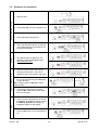
1
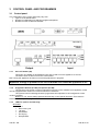
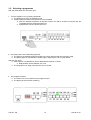
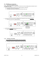
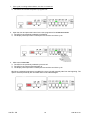
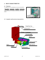
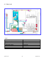
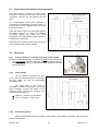
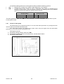
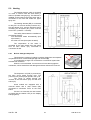
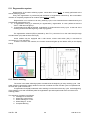
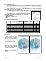
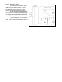
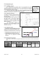
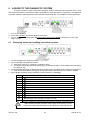
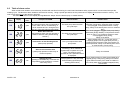
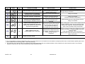
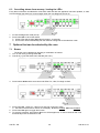
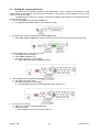
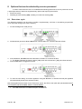
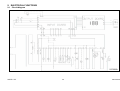
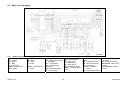
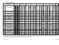
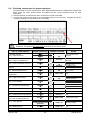
SERVICE MANUAL DISHWASHERS DIVA EDW 2003 ELECTROLUX HOME PRODUCTS ITALY S.p.A. Spares Operations Italy Corso Lino Zanussi, 30 I - 33080 PORCIA /PN (ITALY) Fax +39 0434 394096 Publication no. (Functionality) 599 36 25-10 “fully integrated” 911 987 … EN Produced by: ZM - Solaro (IT) Edition: 2004-01 SOI/TD - PR 60 cm BIG Dishwasher with electronic control 1 599 36 25-10 TABLE OF CONTENTS 1 2 3 Purpose of this manual ........................................................................................................................... 4 GENERAL CHARACTERISTICS............................................................................................................ 4 CONTROL PANEL AND PROGRAMMES ............................................................................................. 5 3.1 Control panel....................................................................................................................................... 5 3.1.1 3.1.2 3.1.3 3.1.4 3.2 3.3 ON / OFF button (S0)..................................................................................................................................5 Programme buttons (S1÷S6) and options (S7÷S8).....................................................................................5 LEDs for options and warnings ...................................................................................................................5 Display ........................................................................................................................................................6 Wash programmes ............................................................................................................................. 7 Options................................................................................................................................................ 7 3.3.1 3.3.2 3.3.3 3.3.4 3.3.5 3.3.6 3.4 3.5 3.6 3.7 “3 in 1”.........................................................................................................................................................7 Extra rinse...................................................................................................................................................7 “1/2 load”.....................................................................................................................................................7 Sanitising ....................................................................................................................................................8 Eco-drying...................................................................................................................................................8 Delayed start...............................................................................................................................................8 Buzzer (installed on certain models, only)........................................................................................ 11 “Beam on floor” function ................................................................................................................... 11 Selecting a programme..................................................................................................................... 12 Programme execution....................................................................................................................... 13 3.7.1 3.7.2 3.7.3 3.8 Cycle start .................................................................................................................................................13 Cycle execution.........................................................................................................................................13 End of cycle ..............................................................................................................................................13 Modifying a programme .................................................................................................................... 14 3.8.1 3.8.2 3.8.3 3.9 4 4.1 4.2 4.3 5 5.1 Cancelling a programme (reset)................................................................................................................14 Changing a programme ............................................................................................................................14 Interrupting a programme .........................................................................................................................17 Sequence of operations.................................................................................................................... 18 BUILD CHARACTERISTICS ................................................................................................................ 19 Structure ........................................................................................................................................... 19 Hydraulic and functional characteristics ........................................................................................... 19 Water circuit ...................................................................................................................................... 20 ELECTRICAL COMPONENTS AND FUNCTIONS .............................................................................. 21 EDW2003 electronic control system................................................................................................. 21 5.1.1 5.1.2 5.2 Functions provided by the mother board...................................................................................................21 Memories contained in the electronic control system................................................................................21 Specifications of actuators and sensors ........................................................................................... 22 5.2.1 5.2.2 5.3 5.4 Components..............................................................................................................................................22 Sensors.....................................................................................................................................................22 Power feed and selection of programmes ........................................................................................ 23 Fill circuit ........................................................................................................................................... 23 5.4.1 5.4.2 5.4.3 5.4.4 5.5 Pressure switches on fill level and anti-overflow system...........................................................................23 Filling system ............................................................................................................................................23 Anti-flooding device...................................................................................................................................23 Operation of the anti-overflow device........................................................................................................24 Control of water filling ....................................................................................................................... 24 5.5.1 5.5.2 5.5.3 5.6 Static filling................................................................................................................................................24 Dynamic filling...........................................................................................................................................24 Level control..............................................................................................................................................24 Water filling time ............................................................................................................................... 25 5.6.1 5.6.2 5.6.3 5.7 5.8 Static filling time ........................................................................................................................................25 Dynamic filling time ...................................................................................................................................25 Interruptions in water filling .......................................................................................................................25 Level control during washing ............................................................................................................ 25 Washing system ............................................................................................................................... 25 5.8.1 5.9 Control of wash pump ...............................................................................................................................26 Heating.............................................................................................................................................. 27 5.9.1 5.10 Built-in detergent dispenser ......................................................................................................................27 Draining ......................................................................................................................................... 28 5.10.1 5.11 5.12 “Siphon” effect...........................................................................................................................................28 Regeneration system .................................................................................................................... 29 Resin washing ............................................................................................................................... 29 5.12.1 5.12.2 5.13 “Blending” function ....................................................................................................................................30 Table of regeneration values.....................................................................................................................30 Drying ............................................................................................................................................ 30 SOI/TD - PR 2 599 36 25-10 5.13.1 5.14 5.15 ”Turbo-dry” drying .....................................................................................................................................31 Automatic cycle ............................................................................................................................. 32 Turbidity sensor........................................................................................................................... 32 5.15.1 5.15.2 Detection of dirtiness ................................................................................................................................32 Detection of load .......................................................................................................................................32 5.16 Automatic Programme .................................................................................................................. 32 A GUIDE TO THE DIAGNOSTIC SYSTEM.......................................................................................... 33 6.1 Displaying alarms and enabling mechanical systems ...................................................................... 33 6.2 Table of alarm codes ........................................................................................................................ 34 6.3 Cancelling alarms from memory / testing the LEDs ......................................................................... 36 7 Options that can be selected by the user ............................................................................................. 36 7.1 Buzzer............................................................................................................................................... 36 7.2 Setting the regeneration level ........................................................................................................... 37 7.3 Rinse-aid dispensing ........................................................................................................................ 38 8 Options that can be selected by service personnel .............................................................................. 39 8.1 Extra rinse cycle................................................................................................................................ 39 8.2 Functional test cycle ......................................................................................................................... 40 6 8.2.1 8.2.2 Executing the test cycle ............................................................................................................................40 Phases in the test cycle ............................................................................................................................40 8.3 8.4 Pulse washing................................................................................................................................... 41 Exiting the diagnostic mode.............................................................................................................. 41 9 ELECTRICAL FUNCTIONS.................................................................................................................. 42 9.1 Circuit diagram.................................................................................................................................. 42 9.2 Basic circuit diagram......................................................................................................................... 43 9.2.1 Button to electrical diagrams.....................................................................................................................43 9.3 Table of programmes........................................................................................................................ 44 9.4 Checking components for proper operation ..................................................................................... 45 10 A QUICK GUIDE TO SPECIAL FUNCTIONS ...................................................................................... 47 SOI/TD - PR 3 599 36 25-10 1 Purpose of this manual The purpose of this manual is to provide service personnel (who already have the basic knowledge necessary for repairing dishwashers) with information on dishwashers equipped with the EDW2003 electronic control system, which are produced in the Solaro (MI - Italy) factory. The EDW2003 control system is composed of a main (input) board, a display (output/interface) board housed in the control panel, and a mother board housed in the lower part of the appliance. The subjects covered in this manual are: • General characteristics • Control panel and programming • Build features • Electrical components and their operation • Guide to the diagnostic system • Operation of electrical systems For detailed information on the water circuits and build characteristics of the appliance, refer to the Service Manual for the “DIVA 60cm” (publication no. 599 35 55-25). Work on electrical equipment must be performed by qualified personnel, only. Pull out the power plug before working on internal components. 2 GENERAL CHARACTERISTICS Important When the appliance is plugged in, mains voltage is present on all circuit boards even if the ON/OFF button is OFF. Power supply ⇒ Total power drawn ⇒ Water supply ⇒ Load capacity ⇒ Dimensions: - width ⇒ - height ⇒ - depth ⇒ Controls - Power up / Power down ⇒ - Selection of programmes/options⇒ - Display ⇒ Washing systems ⇒ Water fill level control ⇒ Water heating ⇒ Temperature control ⇒ Drying systems ⇒ Safety systems / Alarms ⇒ SOI/TD - PR 230 - 240 V / 50 Hz (limits 187-254 V) 2300 W Min. / Max. Pressure: 5 - 80 N/cm2 12 Place settings 59.6 cm 81.8 -87.8 cm (DIVA 60 cm BIG 86.8 – 92.8 cm) 55.5 cm ON/OFF button By button (min. 3, max. 9) 2.5 digit display, backlit characters and/or LEDs Combined / Pulse Pressure switch + Software Heating element enclosed in tube (2100 W) NTC temp. sensor Activ / Turbo Full protection of water/electrical systems and Software 4 599 36 25-10 3 CONTROL PANEL AND PROGRAMMES 3.1 Control panel The configuration of the control panel may vary with: Type of circuit boards used Number of pushbuttons for selecting programmes/options Number of LEDs or backlit characters Output Input 3.1.1 ON / OFF button (S0) This button is installed on all EDW2003 units and is used to turn the appliance on and off. The button does not lean out from the control panel. NB: Turning the appliance off does not cancel the programme in progress. IMportant: Voltage is present on the circuit boards even when the appliance is off! 3.1.2 Programme buttons (S1÷S6) and options (S7÷S8) The functions and number of buttons depends exclusively on the software in the appliance, which can be equipped with a minimum of 3 and a maximum of 9 buttons. The system used for selecting the wash programmes also depends on the configuration of the model in question. Buttons S1, S2, S3 are always present because they control special functions. Each button is associated with a specific programme. 3.1.3 LEDs for options and warnings OPTIONS: • 3 in 1 • Extra rinse cycle • 1/2 load • Sterilisation • Eco-drying • Delayed start SOI/TD - PR 5 599 36 25-10 INDICATORS & ALARMS: • Time to end of cycle: lights up when display shows the time remaining until the end of the cycle. • No salt: lights up when regeneration salt requires replenishment. If the “regeneration level” is set to 1 (no regeneration) this LED does not light up. • No rinse aid: lights up when rinse aid must be added. • Water off: lights up when the water feed to the appliance is shut off. • Filter: lights up regularly. Reminds user to clean the filters. • Door: lights up when door is open. • End of cycle: lights up when the cycle has ended. NB: The operation and presence of the LEDs depends on the software in the appliance. All the LEDs are located near a “programme” or “option” button and indicate that it has been selected. The LEDs stay lit during the entire cycle. 3.1.4 Display The display, which is composed of 2.5 digits, may indicate: The time in minutes remaining until the end of the programme: The value is counted down from minute to minute and is updated at the end of every phase in the programme (when this occurs, the countdown may decrease by more than one minute at a time or stop for a longer time than previously). The end of the cycle[0] The delayed start time in hours, if set (from 1 hr to 19 hrs) The time decreases one hour at a time; during the final hour, it decreases one minute at a time The regeneration level selected The alarm code, if a malfunction has occurred The status of special functions (disabling of rinse-aid and buzzer) The status of functions that can be selected by the service technician. SOI/TD - PR 6 599 36 25-10 3.2 Wash programmes The number and types of wash programmes and options vary with the configuration of the model. I3 Short intensive 68 2 ☺ ☺ ☺ ☺ ☺ N2 Normal (maximum speed) 50 -- 68 1 ☺ ☺ ☺ ☺ N3 Delicate -- 55 1 ☺ ☺ ☺ ☺ ☺ Delicate without prewash -- 55 1 ☺ ☺ ☺ ☺ ☺ Normal 3 rinses Normal 3 rinses without prewash Axx Energy label Fast Energy label Auto performance Energy label Auto 50-65°C -- 68 2 ☺ ☺ ☺ ☺ ☺ 68 2 ☺ ☺ ☺ ☺ ☺ 60 max 55 max Q1 Q4 Q5 Q6 N4 120’ 88‘ 100‘ ☺ 98‘ ☺ 89‘ ☺ 102‘ ☺ 93‘ 1 1 ☺ ☺ ☺ ☺ ☺ ☺ ☺ ☺ ☺ ☺ ☺ ☺ ♦ ☺ 162‘ 65 max 1 ☺ ☺ ☺ ☺ ☺ ☺ ☺ 141‘ -- 50-68 1 ☺ ☺ ☺ ☺ Short -- 50 1 ☺ ☺ ☺ ☺ ☺ Soak Short 30 min Dish heating -- -65 max -- ---- ♦ ♦ 12‘ --- ☺ ☺ ☺ ☺ ☺ 31‘ Crystal ware and glasses -- 45 1 N6 E1 E4 E5 Auto 3.3 ☺ Min. ~ ☺ N5 Q7 ♦ ♦ ♦ ♦ ♦ ♦ ♦ Eco drying ☺ ☺ ☺ ☺ “Tablet” 2 Bio detergent 68 Extra rinse Half load 55 3 in 1 No. of rinses Intensive (maximum speed) Programme Sterilisation Wash (ºC) I2 Type Prewash (ºC) Possible options ----- ♦ ♦ ☺ ☺ ♦ ♦ ♦ ☺ ♦ ☺ 134‘ 92‘-115’ 52‘ 30‘ ☺ 71‘ Options 3.3.1 “3 in 1” This option is selected by pressing the relative button and remains selected until the button is pushed again.. The option modifies the phases in the programme to optimise operation when “3 in 1” detergent tablets are used and is not available in the “Soak” and “Dish heating” cycles: The length of the programmes and the temperatures are varied to dissolve the detergent tablets Water exchange (dilution drainage) is diminished Rinse-aid is not dispensed Regeneration (washing of resins) is disabled 3.3.2 Extra rinse This option can be temporarily selected by pressing the relative button, if present, or by using the “Service” mode (see 10.5.1). It is not available in the “Soak” and “Dish heating” cycles: A rinse with pulse washing is added that lasts around 9 minutes. 3.3.3 “1/2 load” • using the 1/2 load button When this button on the control panel is pressed, certain parameters in the selected wash cycle are modified with respect to the standard cycle. The wash cycle is optimised to handle the reduced amount of dishes loaded into the machine. This option is not available in the “Automatic”, “Short”, “Short 30 min”, “Soak”, “Crystal ware” and “Dish heating” cycles: Prewash is skipped (if included in cycle) Wash temperature is lowered Programme is shortened (down to a minimum of 36 minutes) • using automatic 1/2 load detection When the 1/2 load button is not installed, certain programmes can be set to automatically detect a 1/2 load by measuring variations in temperature during the first heating phase The temperature and length of washing are reduced SOI/TD - PR 7 599 36 25-10 This option is not available in the “Short Intensive”, “Intensive Maximum Speed”, “Short”, “Short 30 min.”, “Soak”, “Dish Heating” and “Crystal Ware” cycles. 3.3.4 Sanitising This special option sanitises the dishes and is not compatible with the “Crystal Ware” cycle. During the final hot rinse, a temperature of 68ºC is maintained for 10 minutes. 3.3.5 Eco-drying This option is temporarily selected by pressing the relative button. It is available in all programmes with at least 15 minutes of drying time (excluding “Short Intensive”, “Short”, “Short 30 min”, “Soak” and “Dish Heating”): Drying time is reduced to only 15 minutes “Energy Label” programmes are shorted by 39 minutes; all other programmes are shortened by 9 minutes 3.3.6 Delayed start This option enables the user to delay the start of the washing cycle for a minimum time of 1 hour to a maximum time of 19 hours from the moment the option is set. The appliance must not be turned off during the countdown. Selecting delayed start after the programme has been selected: 1. With door open, turn the appliance on by pressing button S0 The appliance is set to the selection mode. All the programme buttons and options are now available. After the desired programme is selected, options can still be chosen as long as they are compatible with the selected programme. 2. Press the button for the desired programme: The LED for the selected programme lights up to show that the selection has been made. The display lights up and the time remaining (from beginning to end of cycle) flashes. SOI/TD - PR 8 599 36 25-10 3. Press delayed start button S7: The LED for the selected programme is lit. LED LD7 indicating delayed start is lit. The display flashes the delayed start time. Every time button S7 is pressed, the delayed start time increases by 1 hour up to a maximum of 19 hours: When the selection exceeds 19, the system begins the count again starting from 0. 4. The time set on the display is stored and the countdown to start begins: The LED for the selected programme is lit. LED LD7 indicating delayed start is lit. The display shows the delayed start time. SOI/TD - PR 9 599 36 25-10 Selecting delayed start before the programme is selected: 1. With door open, turn the appliance on by pressing button S0 The appliance starts up in the selection mode. All the programme buttons and options are now available. After the desired programme is selected, options can still be chosen as long as they are compatible with the selected programme. 2. Press delayed start button S7: LED LD7 is lit. The display flashes the delayed start time. NB: Every time button S7 is pressed, the delayed start time increases by 1 hour up to a maximum of 19 hours: When the selection exceeds 19, the system begins the count again starting from 0. SOI/TD - PR 10 599 36 25-10 3. Press the button for the desired programme: The LED for the selected programme lights up to show that the selection has been made. The display lights up and the time remaining (from beginning to end of cycle) flashes. LED LD7 is lit. 4. Close the door, the time set on the display is stored and the countdown to start begins The LED for the selected programme is lit LED LD7 indicating delayed start is lit The display shows the delayed start time 3.4 Buzzer (installed on certain models, only) This series of dishwashers is not normally equipped with a buzzer, but some models may have one. The buzzer is a device that signals the End of cycle and an Alarm should one occur. The buzzer goes off three times at the end of the cycle and is immediately silenced when the door is opened. 3.5 “Beam on floor” function In “fully integrated” dishwasher models a device projects a beam of coloured light onto the floor to indicate the performing of the cycle or alarm conditions. The “beamer” is installed between the door and the inner door as described in the Service Manual “Accessibility” code 599 35 87-82. When the end of cycle has been reached the signal of the beamer stops. SOI/TD - PR 11 599 36 25-10 3.6 Selecting a programme With the dishwasher OFF and door open: 1. Turn the appliance on by pressing button S0 The appliance is set to the selection mode All the programme buttons and options are now available After the desired programme is selected, options can still be chosen as long as they are compatible with the selected programme Delayed start can be selected; see 3.3.6 2. Press the button for the desired programme: The LED for the selected programme lights up to show that the selection has been made The display lights up and the time remaining (from beginning to end of cycle) flashes With the door open: Other options or modifications can be added before the door is closed Delayed start can be selected; see 3.3.6 The programme can begin only when the door is closed 3. The programme starts The LED for the current phase in the programme is lit The display shows the time remaining SOI/TD - PR 12 599 36 25-10 3.7 Programme execution 3.7.1 Cycle start With door closet and after the countdown has elapsed the selected programme automatically starts. At this point, the delayed start time cannot be changed and no other options can be selected The programme in progress can be cancelled, see 3.8.1 The programme can be modified, see 3.8.2 3.7.2 Cycle execution The LED for the selected programme is lit. The display shows the minutes of wash time remaining. The time until the end of the cycle is updated at every new phase in the programme. When the system moves from one phase to another, the time remaining until the end of the cycle may be lowered more than the actual time elapsed. When the system moves from one phase to another, the time remaining until the end of the cycle may stop until the system synchronises. The beamer projects a beam of light. 3.7.3 End of cycle The LED for the selected programme is lit. The display shows “0”. The LED showing the end of the cycle is lit. The beamer switches off. If it is installed and enabled, the buzzer will emit a sequence of sounds at the following intervals: 15 seconds on - 3 minutes off - 15 seconds on – 3 minutes off - 15 seconds on – buzzer remains off. The buzzer is disabled as soon as the door is opened. At the end of the cycle, the “0” on the display can be eliminated by opening and closing the door. After the door has been closed, the appliance will automatically be set to the selection mode. Press the S0 button to turn the appliance off completely. SOI/TD - PR 13 599 36 25-10 3.8 Modifying a programme 3.8.1 Cancelling a programme (reset) A cycle that is in progress or is programmed to start at the end of the delayed start countdown can be cancelled at any time: 1. The cycle is proceeding normally with no alarms, the door is closet but: The LED for the cycle in progress is lit. The display shows the time remaining until the end of the cycle. 2. Open the door and press the S1 and S2 buttons at the same time for around 2 seconds. the LED for the cycle in progress flashes. 3. After around 2 seconds all the indicators will turn off. the cycle has been cancelled. 3.8.2 Changing a programme 1. If the programme has been selected but has not yet started: The LED for the cycle in progress is lit. The display shows time remaining until the end of the cycle. SOI/TD - PR 14 599 36 25-10 2. Press the button for the new programme. The LED for the cycle in progress is lit. The display shows time remaining until the end of the cycle. NB: all the options selected previously are cancelled and must be selected again. 3. Before closing the door it is still possible to change the programme choice. If no button is pressed, once the door has been closed the cycle will start. NB: The cycle will begin only if the door is closed. If a delayed start has also been selected: The programme has been selected but has not yet started. The LED for the selected cycle is lit. LED LD7 for delayed start time is lit. The display flashes the time set for delayed start. Open the door carefully and press the button for the new programme. The delayed start time that was previously programmed remains in memory. The options selected previously are cancelled and must be selected again. The LED for the new cycle is lit. LED LD7 for delayed start time is lit. The display flashes the time until the end of the cycle for around 2 seconds. The display then flashes the time set for delayed start. SOI/TD - PR 15 599 36 25-10 1. If the cycle is running without alarms, the door is closed but: The LED for the selected cycle is lit. The LED that indicates the phase in progress is lit. 2. Open the door and press the button for the new programme for at least 6 seconds. The LED for the previously selected cycle flashes. The display shows (but does not flash) the time until the end of the cycle. 3. After around 6 seconds: The LED for the previously selected cycle turns off. The LED for the new programme lights up. The display shows (but does not flash) the time until the end of the cycle. NB: When a selected programme is modified, the new cycle will generally start from the beginning. The options selected previously are cancelled and must be selected again. SOI/TD - PR 16 599 36 25-10 3.8.3 Interrupting a programme Opening the door If the appliance is in the selection mode: All the indicators on the control panel stay lit when the door is opened. Power is supplied to the circuit boards for the entire time the appliance is on. If the appliance is in the washing cycle: When the door is opened (carefully), all the indicators on the control panel stay lit for the entire time that the washer is on. When the door is closed, the machine automatically resumes the washing cycle. Shutting off the appliance 1. Shut off the machine by pressing the S0 button (there are no limits on time) No previously selected option is cancelled All indicators on the control panel turn off. 2. To restart the cycle, press button S0 once again The cycle resumes from the point at which it was interrupted, but with a slight delay No other button needs to be pressed All the indicators on the control panel appear exactly the way they were before the interruption Important: If the appliance is turned off or the door is opened for more than 30 seconds during the drying cycle, the cycle will end after the regeneration phase and the appliance will be set to the selection mode when it is turned back on. Power failure 1. If a drop in mains voltage occurs, the appliance behaves as it had been shut off by pressing button S0. When the mains voltage is restored, the appliance behaves as it were turned on by pressing button S0. When the power is restored after a power failure, the cycle automatically resumes from the point where it was interrupted and no button needs to be pressed. SOI/TD - PR 17 599 36 25-10 3.9 Sequence of operations SELECTING THE CYCLE 1. Open the door. 2. Press button S0 to turn the appliance on. 3. Select the desired programme. END EXECUTION OF CYCLE START 4. Select the delayed start time (if desired) or the desired option (if permitted in the programme selected) 5. The delayed start countdown or the selected cycle will automatically start after closing the door 6. The time until the end of the cycle (in minutes) will decrease. The time is updated at each new phase in the cycle 7. To interrupt a programme in progress, turn off the machine using the S0 button or open the door NB: to restart, press the S0 again and/or close the door 8. To cancel a programme in progress, press the S2 – S3 buttons at the same time for 2 seconds At the end of the programme, the buzzer (if installed) will sound a number of times, the END OF CYCLE LED will light up, and [0] will appear on the display 9. Press the S0 button to turn the appliance off SOI/TD - PR 18 599 36 25-10 4 BUILD CHARACTERISTICS 4.1 Structure The appliance can be subdivided into four main assemblies: - BASE AREA – DOOR AREA – TUB AREA – WATER UNIT The machine is housed in an assembly of individual removable parts composed of a front panel at the bottom and two side panels. 4.2 Hydraulic and functional characteristics Turbo Dry Fan Drying duct Fill tank + Condenser Counterweight Base Heating element Water softener Sump SOI/TD - PR Wash pump Drain pump 19 599 36 25-10 4.3 Water circuit LEGEND 1 - Fill hose 2 - Fill hose with "Acquacontrol" device 3 - Fill solenoid 4 - Regeneration solenoid 5 - Air-Break 6 - Steam condenser 7 - Regeneration chamber 8 - Salt tank 9 - Resin tank 10 - Level pressure switch SOI/TD - PR 11 - Anti-overflow pressure switch 12 - Sump assembly 13 - Wash pump 14 - Heating element (enclosed in tube) 15 - Drain pump 16 - One-way valve 17 - Drain hose 18 - Drying duct/Fan 19 - Anti-flooding device 20 599 36 25-10 5 ELECTRICAL COMPONENTS AND FUNCTIONS 5.1 EDW2003 electronic control system The EDW2003 electronic control system is composed of a main board (“input board”) and a display board (“output”) that are housed in the control panel, and a “mother board” (fig. 1), which is located at the bottom of the appliance (toward the front). The board is anchored to the base by a plastic support. fig. 1 5.1.1 Functions provided by the mother board INPUT AND OUTPUT BOARDS LEDs Display Buttons µP SENSORS (Buzzer) MAIN BOARD ELECTRIC LOADS Acquires cycle programming through the input and output boards. Powers all the electrical components (solenoids, wash pump, detergent/rinse aid dispenser, drain pump, heating element, fan motor) Controls the temperature of the wash water using a signal from an NTC sensor, and controls the speed of the wash pump using a signal from a tachometric generator. Monitors the pressure switches and the rinse aid / salt sensors. 5.1.2 Memories contained in the electronic control system µP External serial port Asynchronous ROM Power failure and machine status RAM Internal serial port Synchronous EEPROM Configuration of appliance Description of cycle The main board is equipped with an EEPROM that is external to the microprocessor and which is used to store data on machine configuration, description of the cycle, and status of the cycle in case of a power failure or alarm. The configuration data is programmed at the factory by a computer with a DAAS interface. This data determines the operation of the appliance (number and types of programmes, options, LEDs, etc.). SOI/TD - PR 21 599 36 25-10 5.2 5.2.1 Specifications of actuators and sensors Components TYPE OF COMPONENT POWER RATING TYPE OF CONTROL Wash pump Max 250W Triac Drain pump Max 100W Triac Heating element Max 2100W Relay Water fill solenoid Max 10W Triac Regeneration solenoid Max 10W Triac Detergent and rinse-aid solenoid Max 10W Triac Fan motor Max 10W Triac 5.2.2 Sensors TYPE OF SIGNAL TYPE OF COMPONENT Salt sensor Digital 5 Volt Reed Rinse-aid sensor Digital 5 Volt Reed Analogue 5 Volt * NTC Analogue 5 Volt Opto-electronic Frequency Tachometric generator Level sensor Digital High voltage Pressure switch Door closure sensor Digital High voltage Switch Anti-flooding sensor Digital High voltage Switch SENSOR Temperature sensor Turbidity sensor (on certain models, only) Tachometric sensor * NTC temperature sensor COMPARATIVE TABLE OF * NTC VALUES Temperature 10°C 25°C 60°C 90°C SOI/TD - PR Nominal value Ω 9655 4850 1205 445 22 599 36 25-10 5.3 Power feed and selection of programmes The main board is powered up when power button (PU) contacts 1-5 and 2-4 are closed. The connectors involved are A2 (neutral) and B1 (line). The control/display board (user interface) is powered by 5V supplied by the main board, so programmes can be selected when the main board is turned on. When the door is closed, the main board detects the closed contacts on switch (IP) between connectors B2-D1 and starts the wash programme. The same switch supplies power to the electrical components. When the door is opened, power is shut off to the various loads and the cycle is paused. 5.4 Fill circuit 5.4.1 Pressure switches on fill level and anti-overflow system The level of water during filling is controlled by level pressure switch (A) • The anti-overflow pressure switch (B) makes sure that the level of water during filling does not exceed the safety threshold (overflow through the door). 5.4.2 B A Filling system The fill solenoid is powered by triac TY2 on the circuit board (connector C7) through the door switch (IP) and the anti-flooding microswitch (DA). The water level in the sump is controlled by pressure switch (RL). The circuit board constantly monitors the status of the pressure switch through the “sensing” line connected to connector C5: “EMPTY” if contacts 1-2 are closed “FULL” if contacts 1-3 are closed 5.4.3 Anti-flooding device When the anti-flooding device is tripped, contacts (DA) on the relative microswitch open and cut off power to the solenoid. SOI/TD - PR 23 599 36 25-10 5.4.4 Operation of the anti-overflow device If the pressure switch (PA) on the antioverflow system is activated, the closed “FULL” contact (1-3) starts the drain pump (PS), which operates until the contact switches to “EMPTY” (1-2). If the door is opened or the machine is shut off, the drain pump shuts off. 5.5 Control of water filling The quantity of water required to perform the washing cycle is exclusively determined by the closure of the electrical contacts in the pressure switch when it switches from EMPTY to FULL. In order to keep a constant amount of water in the machine, if the pressure switch should re-open to EMPTY, fresh water is introduced until the switch returns to FULL. The fill cycle is subdivided into the following sub-cycles: 5.5.1 Static filling With the motor switched off, the fill solenoid is activated and water is introduced into the appliance until the pressure switch switches to FULL. 5.5.2 Dynamic filling Dynamic filling occurs by starting the wash pump, which causes the pressure switch to switch to the EMPTY position. At this point, the fill solenoid is actuated and water enters until the pressure switch moves to the FULL position. The speed of the motor determines the quantity of water loaded into the machine: the electronic control system actuates the wash pump at a speed that depends on the washing system that will be executed after the machine fills: If washing is «ctrl» (constant speed): the motor is gradually accelerated to 2800 RPM. If washing is «PW» (pulse): the motor is gradually accelerated to 1900 RPM. N.B.- For more information on these washing systems, see the table of washing programmes. 5.5.3 Level control The water circuit operates with greatest efficiency when the pressure switch remains constantly on FULL, since the water contained in the sump enables the pump motor to operate constantly and without the fluctuations in speed that are caused when the pump cavitates. The fill solenoid is disabled when the pressure switch is set to FULL. SOI/TD - PR 24 599 36 25-10 5.6 Water filling time The maximum time that the fill solenoid stays open is subdivided over various sub-phases in the fill cycle. 5.6.1 Static filling time S.T. = max 90 seconds: this is the maximum time allowed for the pressure switch to switch to FULL. If the switch does not move to FULL within the established time, the electronic control system signals an alarm [1 0] and interrupts the washing cycle. 5.6.2 Dynamic filling time D.T. = S.T. x 3: this is the maximum time allowed for the pressure switch to switch to FULL during the entire fill phase. • If the pressure switch does not switch to FULL within the time allowed (S.T. x 3) the electronic control system shuts off the fill solenoid and the heating element (if it is on), and then completes the washing cycle. When this occurs, alarm [F0] is stored internally but is not shown to the user. The alarm can only be displayed to the service technician through a specific procedure. • During dynamic filling for washing at 2800 RPM, if the pressure switch fails to switch to the FULL during the first 60 seconds, the electronic control system signals an alarm [1 0] and interrupts the washing cycle. 5.6.3 Interruptions in water filling If the fill cycle is interrupted by opening the door or a power failure, the elapsed time up to that point is stored. When the door is closed or power is restored, water filling will resume from the point of interruption and the operating time from that point will be added to the previous time. 5.7 Level control during washing When the fill phase is complete, the appliance shifts to the washing phase. During this phase, which is executed with cold or heated water, the status of the pressure switch is monitored constantly to ensure that the water system is operating efficiently, and the water level is topped up if necessary. If the pressure switch returns to EMPTY during washing, the fill solenoid is activated for a maximum time of S.T. x 3 (maximum total fill time). If this time is exceeded, the washing cycle is completed but no more water is introduced. When this occurs, an alarm [F0] is stored internally but not shown to the user. The alarm can only be displayed to the service technician through a specific procedure. 5.8 Washing system This appliance features the conventional washing system in which mechanical washing action is obtained from the wash pump, which circulates water through the water circuit, thus rotating the two spray arms simultaneously. The wash pump, which is equipped with a tachometric generator, is powered by an asynchronous motor equipped with a starting capacitor (3µF – 450V). The motor rotates anti-clockwise (as seen from the side of the impeller). SOI/TD - PR 25 599 36 25-10 To optimise washing performance, this appliance offers two different washing systems: «ctrl» «PW» Washing at a constant motor speed of 2800 RPM.(max. motor speed). Variable-speed (pulse) washing at 1600 > 2800 RPM. This system is controlled by the electronic control system, which sequentially activates the washing motor at two different speeds (a minimum and maximum speed) for brief intervals. MOTOR SPEED PERIOD OF TIME Normal 1600 RPM 4 sec Pulsation PW1 2800 RPM 0.8 sec The motor speeds for «ctrl» and «PW» can be programmed; for further information, see the table of cycles for the specific model. 5.8.1 Control of wash pump The wash pump (PL) is powered by triac TY4 on the main board (connector C3), through the door interlock switch (IP) and the start button (PU). The main board controls the speed of the pump motor using the signal from the tachometric generator (T), connected across connectors E1-E2. This signal is used for: Controlling washing systems «ctrl» and «PW» Controlling the safety systems on the pump motor, and the relative alarms Controlling dynamic filling SOI/TD - PR 26 599 36 25-10 5.9 Heating The heating element, which is enclosed in a tube, is used to heat the wash water (it does not operate during drying). The element is installed on the intake to the wash pump and is connected to the tube that feeds the upper spray arm. The heating element (RR) is connected to relay RL1 on the main board (connector A1), the start button (PU), and the pressure switch controlling the fill system (RL), which must be set to FULL (contacts 1-3 closed). Two safety thermostats are installed on the heating element: - one thermostat resets automatically (and trips at 98ºC) - the other is a fuse (that opens at 206ºC) The temperature of the water is controlled by the main board using the signal from an NTC sensor (ST) connected to connectors G5-G6. 5.9.1 Built-in detergent dispenser This dispenser consists of a plastic container divided into two separate compartments which contain detergent (A) and rinse-aid (B). It is engaged by a single coil connected to a mechanical system that actuates both functions. When the coil is activated, it moves a set of levers that engage the mechanism, which first delivers the detergent and then delivers the rinse-aid. B A The dispenser coil (DD) is powered by the main circuit board through triac TY5 (connector D7) at the proper points in the cycle. The circuit is closed through the contacts in the start button (PU) and the door switch (IP). Some models are equipped with a rinse-aid sensor with a reed contact (SB) connected to connectors F3-F4 on the main board. If there is no rinse-aid, the reed contact is closed and the relative LED (on the display board) lights up. SOI/TD - PR 27 599 36 25-10 5.10 Draining The drain pump (PS) is powered by triac TY3 (connector C1) through the contacts on the start button (PU) and the door switch (IP). At the end of the drain phase, a check is made to verify whether the contact on the pressure switch is open (in the EMPTY position). If it is open, the cycle is allowed to move on to the next phase. If malfunctions in the drain system keep the pressure switch stuck on FULL (presence of water in the water circuit), the drain phase is repeated. After the drain phase is repeated, the electronic control system again checks the status of the pressure switch. If it is still on FULL, a drain failure alarm [i20] is signalled. The timeout for each of the two drain phases is 120 seconds. Note: Washing programmes always begin with a drain phase. 5.10.1 “Siphon” effect If the drain tube is incorrectly positioned, the so-called “siphon effect” may occur, in which case an alarm is displayed iF0 (see 9.1). The problem is particularly likely to occur during execution of the “declaration cycle”: although the drain pump shuts down at the end of the (partial) drain phase, water continues to be expelled from the machine because the drain tube is incorrectly positioned. When this occurs, water loaded by the fill solenoid during the next phase is directly expelled, so the “full contact” on the pressure switch does not close before its “time out”. Thus, if alarm iF0 occurs, it is a good idea to make sure the drain tube is correctly positioned as shown in the instruction manual. SOI/TD - PR 28 599 36 25-10 5.11 Regeneration system Regeneration of the water softening system, which takes around 4 min, is usually performed at the start of the drying phase. Every time regeneration is performed (with activation of regeneration solenoid 4), the accumulation chamber is completely emptied of its contents (about 230 cc of water). Regeneration is not carried out at every washing cycle, but at intervals that are determined by the programmed regeneration level: If regeneration level [1] is selected (no regeneration), regeneration is never performed and the "SALT" LED does not light up If regeneration level [10] is selected, regeneration is performed twice every cycle: at the end of the washing phase and at the beginning of the drying phase. The regeneration solenoid (ER) is powered by triac TY1 (connector C9 on the main board) through the start button (PU) and the door switch (IP). Some models may be equipped with a salt sensor, whose reed switch (SS) is connected to connectors F1-F2 on the board. If there is no salt in the machine, the contact closes and lights up the relative LED (on the display board). 5.12 Resin washing The resins in the water softening system are washed at the beginning of every washing cycle. Salt water solution (regeneration water) remains in the resin container from the time the cycle is completed until the time next cycle is carried out. If regeneration level [10] is selected, resin washing is carried out twice every cycle: at the beginning of the washing cycle and immediately after the regeneration procedure performed at the end of the final washing phase. The sequence of phases is as follows: a. Drainage for 30 seconds b. Water fill to normal level c. Water draining for 10 sec. d. Water filling for 15 sec. e. Complete draining SOI/TD - PR 29 599 36 25-10 5.12.1 “Blending” function This function is performed inside the fill tank during the water fill phase. Depending on the position of the selector, softened water is automatically blended with the unsoftened water present in the appliance. The softened water is introduced from the softening system into the sump, while the unsoftened water flows through an open by-pass valve directly through the steam venting ring. When the regeneration system is set to levels [1-4], it is advisable to activate the BLENDING function to mix softened water with unsoftened water. This function optimises the consumption of salt, thus preventing corrosion of glassware when the water is very soft. When the BLENDING function is activated, the percentage of unsoftened water introduced into the dishwasher is 15%. The BLENDING function is activated using the selector knob located inside the tub, on the left side, in the vicinity of the steam venting grille: Position of selector position 1 = blending enabled. position 2 = blending disabled. 5.12.2 Table of regeneration values Level 1 2 3 4 *5 6 7 8 9 10 Water fill between Time Position of regeneration regeneration tank Display procedures solenoid opens selector litres sec no. 1L --0 1 2L 130 240 1 3L 94 240 1 4L 70 240 1 5L 53 240 2 6L 37 240 2 7L 20 240 2 8L 15 240 2 9L 10 240 2 10 L 3 2x240 2 * “5” = Level set at factory Position of tank selector: “2” Hardness of water treated º F (TH) 0>8 9 > 14 15 > 20 21 > 30 31 > 40 41 > 50 51 > 60 61 > 70 71 > 80 81 > 90 º D (dH) 0> 4 5>8 9 > 11 12 > 17 18 > 22 23 > 28 29 > 33 34 > 39 40 > 45 46 > 50 5.13 Drying ACTIV-DRY TURBO-DRY In these dishwashers, the dishes are dried by a steam condensation process. This drying system is based on the natural circulation of the hot air produced during the hot rinse, when steam circulates inside the condenser on the fill tank. The condenser is a (cold wall) condensation chamber filled with water, against which the hot air is ducted. This contact between the hot air and the cold wall generates a process of condensation. The type of drying system can be either “activ-dry” or “turbo-dry”, depending on the model of machine. SOI/TD - PR 30 599 36 25-10 5.13.1 ”Turbo-dry” drying On some models, a forced-air drying system is used. Steam is drawn in by a fan inside the upper duct and then ducted towards the condenser in the fill tank, from where it returns to the tub via the steam venting ring. The fan motor (MV) is powered by triac TY6 (connector D3 on the main board) through the start switch (PU) and the door switch (IP). The drying time is variable and pre-defined for each washing cycle. In some programmes, the fan operates for around 20 minutes even after the end of the cycle. It shuts off (and will not restart) when the door is opened. SOI/TD - PR 31 599 36 25-10 5.14 Automatic cycle 5.15 Turbidity sensor Some models fitted with a turbidity sensor can be equipped with a special “Automatic” programme that optimises the cycle to compensate for the quantity of dishes loaded and the amount of dirt on them. The sensor is located on the outside of the sump and directly contacts the water. The NTC sensor that controls wash water temperature and the infrared turbidity sensor that checks the turbidity of the water (and thus the amount of dirt deposited on the dishes) are contained in a single component.. 5.15.1 Detection of dirtiness The degree of turbidity is measured during the cold prewash. A LED powered by the main board (connector G7) projects a beam of light at a photo receiver. In the photo receiver circuit (connector G8 on the main board - G6 is the common connection), a current circulates that is proportional to the amount of light received (and is thus inversely proportional to the degree of turbidity). The microprocessor measures the signal in the circuit and determined the most appropriate cycle for the amount of dirt dissolved in the water. 5.15.2 Detection of load The quantity of dishes loaded (full or 1/2 load) is detected during the first heating phase in the washing cycle by measuring the speed of water temperature increase (NTC sensor, connector G5). temperature 1/2 load threshold Full load: when the slope of the curve is less than the programmed standard threshold Half load when the slope of the curve is greater than the programmed standard threshold full load time 5.16 Automatic Programme Shown below are the variations in programme phases which are made as a function of dirt level and load. Type Load Full Full Half full Half full SOI/TD - PR Phases in the programme Very dirty? Yes No Yes No Prewash Wash cold 68º C 55º C 55º C 50º C First rinse Second rinse Hot rinse Drying 68º C 24 min. cold cold 32 no 599 36 25-10 6 A GUIDE TO THE DIAGNOSTIC SYSTEM A single procedure is used to access the diagnostic system, also known as the Service mode. Once this mode is accessed, it is possible to read / cancel alarms, check the various components in the appliance for proper operation, start a diagnostic cycle and select options that are only available to service personnel. 1. Turn off the appliance. 2. Press and hold down buttons S1-S3 at the same time. 3. Turn on the appliance using button S0 while holding down buttons S1-S3 until LEDs LD1, LD2, LD3 begin to flash. 6.1 Displaying alarms and enabling mechanical systems 1. Access the diagnostic mode (see 10.1) 2. Press button S1 to activate this function LEDs LD2, LD3 turn on, while LD1 continues to flash The display shows the first alarm stored [ ix0 ] (to decode the alarm, see the table listing the alarms on pages 27, 28). 3. Press button S1 repeatedly to display the other two alarms and to enable various electrical components. After the first three alarms, the display shows the number corresponding to the function enabled 4. All the display positions can be repeated by pressing button S1 repeatedly. Display 0 0 i 0 4 5 6 7 8 9 10 11 12 i i SOI/TD - PR Function activated Display of last alarm that has occurred Display of the next to last alarm that has occurred Display of the third to the last alarm that has occurred Activation of regeneration solenoid Activation of drain pump Enable water fill solenoid until level reached Heating (only with water at operating level!) Wash pump at 2800 RPM Detergent/rinse-aid dispenser Drying fan (if turbo-dry) Activation of auto-dosing (currently not used) Activation of water hardness sensor (currently not used) Power is supplied to components when the door is closed: open the door to select another activation and then close it again. If the button S1 is not pushed, the system automatically exits the diagnostic mode after 60 sec. 33 599 36 25-10 6.2 Table of alarm codes When an abnormal situation occurs that may interfere with machine functioning, the main board activates a safety system which in most cases interrupts the washing cycle. The last three alarm situations are stored in memory. Using a special procedure, service personnel can display all the alarms stored in memory. The user is only shown four of the alarms in progress. The alarms are shown on the display and signalled with “beeps” from the buzzer (only on certain alarms). Type of alarm Shown to user? Description of ALARM yes Water fill time-out (the pressure switch has not switched to FULL within 90 sec. of static filling, or never switches to FULL during the first 60 sec. of dynamic filling at 2800 RPM) The drain pump starts and then the cycle stops i20 yes Water drain time-out (the pressure switch has not returned to EMPTY after two drain phases lasting 120 sec.) The drain pump starts and then the cycle stops i30 yes Intervention of anti-flooding device (drain pump operates) The cycle stops and the drain pump starts. yes Short circuit on motor triac (wash pump operates continuously at maximum speed) Water fills to operating level (if necessary), other mechanical systems fail to operate and cycle stops. The washing motor operates at max. speed and alarm is displayed. Faulty circuit board no Heating time-out (heating is checked every 3 minutes: the temperature must increase by a certain value every time) The programme is fully executed without heating (and with poor washing performance) Faulty heating element; Safety thermostats have tripped (open); Faulty wiring; Faulty NTC sensor (poor thermal contact); Poor water circulation in tub; Faulty wash pump (impeller stripped) Faulty circuit board i10 i50 i60 SOI/TD - PR Display 34 Status of machine 599 36 25-10 Possible causes Tap closed; Water mains pressure too low; Drain solenoid / wiring faulty; Pressure switch on water circuit plugged; Level pressure switch / wiring faulty; Faulty circuit board (short circuit on solenoid triac) Drain circuit plugged / clogged; Drain pump faulty / obstructed (foreign bodies); Level pressure switch stuck on FULL (1-3); Pressure switch on water circuit plugged; Faulty wiring; Faulty circuit board. Water leakage from tub – sump and various couplings (pumps, line to upper spray arm,etc.); Floating sensor jammed; Faulty microswitch; Fill solenoid jammed; Faulty circuit board (short circuit on solenoid triac). Faulty wiring. Type of alarm Shown to user? Description of ALARM Status of machine i70 no Short circuited or open NTC sensor The programme is fully executed without heating (and with poor washing performance) i80 no Communication error between microprocessor and EEPROM Machine controls inoperative. (*) Faulty circuit board i90 no Improper software configuration Faulty circuit board (Improper software configuration). ib0 no Problem with turbidity detection (if so equipped: calibration timeout) no Problem with washing motor: no signal from tachometric generator (wash pump operates, but there is no signal from the generator) Machine controls inoperative when unit is turned on. (*) The programme runs as though a “very dirty” situation were detected Disconnect the heating element; if the problem persists after timeout, the wash pump will operate at max. speed and an alarm is recorded (the cycle continues) id0 Display iF0 no i0 no Water additions time-out (3 times length of S.T. time-out) The cycle continues until the next phase with no added water and no heating . The fault is corrected after a drainage phase is completed. Possible causes Faulty NTC sensor; Short circuit / open circuit in wiring; Faulty circuit board Faulty turbidity sensor; Faulty wiring to sensor; Faulty circuit board Motor winding open / short-circuited; Motor jammed (foreign bodies); Faulty wiring to washing motor; Faulty motor capacitor; Tachometric generator open / short-circuited; Faulty circuit board Dishes overturned; Main filter clogged; Excessive foam; Poor seal on coupling between sump and pressure switch; Faulty pressure switch / poor connections; Domestic drain outlet improperly positioned (siphon effect, see 5.10.1) No alarm has been stored. (*) If it is impossible to access the diagnostic mode, turn off and then turn on the machine to see whether a temporary block has occurred. Before replacing the circuit board, make sure it is receiving power. Check the following: The continuity of the power cable, the operation of the radio interference filter, the (closed) condition of the contacts on the door interlock switch, the continuity between connectors A2 / B1 on the board and the radio interference filter. SOI/TD - PR 35 599 36 25-10 6.3 Cancelling alarms from memory / testing the LEDs Every alarm should be cancelled after it has been read and after the appliance has been repaired, in order to know whether the alarm has occurred again when the next diagnostic test is run. 1. Access the diagnostic mode (see 6). 2. Press button S2 to cancel the alarms: All the LEDs and the digit [188 ] flash for approx. 30 seconds. This function ends automatically with the machine setting itself to the selection mode. 7 Options that can be selected by the user 7.1 Buzzer The buzzer can be disabled by pressing a combination of buttons: 1. Turn on the unit by pressing button S0. 2. Cancel any cycles that have been selected (see 3.8.1). 3. Press buttons S1-S2 at the same time until LEDs LD1, LD2, LD3 begin to flash. 4. Press button S3. LEDs LD1, LD2 turn off and LD3 continues to flash. the status of the buzzer is shown on the display: 1b buzzer enabled, 0b buzzer disabled 5. Press button S3 again to toggle the function. 6. To store the operation: press button S0 to turn off the appliance; or wait 60 seconds and it will automatically enter the selection mode. SOI/TD - PR 36 599 36 25-10 7.2 Setting the regeneration level The count for “as needed” execution of the regeneration cycle is made by the electronic control system based on the duration of the fill phases and thus on the quantity of water loaded (and not on the number of cycles executed). The adjustment is made over 10 levels. If level [1] is selected, regeneration is not performed and the salt LED does not light. 1. Turn on the appliance by pressing the S0 button. The appliance is automatically set to the selection mode. 2. Simultaneously press and hold down the S1 and S2 buttons: LEDs LD1, LD2 and LD3 begin to flash, which shows the machine will accept new programming. 3. Press the S1 button to call up this function: LED LD1 continues to flash. LEDs LD2 and LD3 turn off. the display shows the current setting. see the table listing the regeneration values. 4. When the S1 button is pressed repeatedly: LED LD1 continues to flash. the display shows the current setting. the regeneration level is increased stepwise until it reaches 10L. 5. To store the new setting: Shut off the appliance using the S0 button. Wait 60 seconds. All the indicators on the control panel shut off. SOI/TD - PR 37 599 36 25-10 7.3 Rinse-aid dispensing Rinse-aid dispensing can be disabled by the user by pressing a combination of buttons. The rinse-aid LED (if present) also shuts off: 1. Turn on the appliance by pressing the S0 button The appliance is automatically set to the selection mode 2. Simultaneously press and hold down the S1 and S2 buttons: LEDs LD1, LD2 and LD3 begin to flash, which shows the machine will accept new programming 3. Press the S2 button to call up this function: LED LD2 continues to flash LEDs LD1 and LD3 turn off the display shows the current setting 0d, function enabled 1d, function disabled 4. Press the S2 button to toggle the function: LED LD2 continues to flash the display shows the current setting 0d, function enabled 1d, function disabled 5. To store the new setting: Shut off the appliance using the S0 button Wait 60 seconds All the indicators on the control panel shut off SOI/TD - PR 38 599 36 25-10 8 Options that can be selected by service personnel In certain cases when the user is not satisfied with washing performance, service personnel can use a special procedure to select two supplementary options that improve performance: • Extra rinse (cold) • Disabling of pulse washing (PW), enabling of continuous washing (Ctrl) 8.1 Extra rinse cycle The following procedure can be used to include a supplementary cold rinse in all washing programmes, which improves rinsing action when necessary. 1. Access the diagnostic mode (see 6). 2. Simultaneously press the S1 and S2 buttons until the LEDs LD1, LD2 and LD3 start to flash. 3. Press S1 button, the LEDs LD2 and LD3 switch off while LD1 continues to flash. The display indicates the function status: [ 0A ] extra rinse not selected, [ 1A ] extra rinse selected. 4. Press the S1 button to toggle the function. 5. To store the new setting: shut off the appliance using the S0 button, or wait 60 seconds (the appliance will automatically be set to the selection mode). NB: If the appliance has a button for an “Extra rinse” option, the LED for the option will operate backwards IF THE OPERATION DESCRIBED ABOVE IS PERFORMED: • The LED will be ON to indicate the option is DISABLED. • The LED will be OFF to indicate the option is ENABLED. SOI/TD - PR 39 599 36 25-10 8.2 Functional test cycle The functional test cycle is a washing programme for use by service personnel only. It can be used to test all the functions in a traditional washing cycle. In effect, a normal cycle is simulated. 8.2.1 Executing the test cycle 1. Access the diagnostic mode (see 6) 2. Close the door 3. Press the S3 button to set the cycle LEDs LD1 and LD2 turn off; LD3 continues to flash; the LED for the phase in progress is lit The display flashes the time to the end of the cycle The programme is executed like a normal cycle. All pause and cancellation functions are available. 8.2.2 Phases in the test cycle Phase Duration Water fill, Turbo enabled 30’’ Water fill 25’’ Pulse washing, dispenser 45’’ opens Drain dilution Water fill --Pulse washing 60’’ Drain dilution Water fill --Controlled washing at 2800 RPM, heating to 60°C Controlled washing at 2800 1200’’ RPM, temp. maintained at 60°C temperature time Notes: • The total duration of the cycle is about 50 minutes. • The resins are washed at the beginning of the first programme executed after the test cycle. SOI/TD - PR 40 599 36 25-10 8.3 Pulse washing Some programmes use a pulse washing (PW) system. The following procedure can be used to modify this system by programming continuous washing «Ctrl» in all cycles where «PW» pulse washing is the default. This modification also enhances washing action in delicate programmes. 1. Access the diagnostic mode (see 6). 2. Simultaneously press the S2 and S3 buttons until the LEDs LD1, LD2 and LD3 start to flash. 3. Press S2 button, the LEDs LD1 and LD3 switch off while LD2 continues to flash The display indicates the function status: [ 0P ] continuous washing enabled, [ 1P ] pulse washing enabled 4. Press the S2 button to toggle the function: [ 0P ] continuous washing enabled “Ctrl”; [ 1P ] pulse washing enabled “PW”. 5. To store the new setting: Press the S0 button and shut off the appliance, or wait 60 seconds (the appliance will automatically be set to the selection mode) 8.4 Exiting the diagnostic mode 1. To exit the diagnostic mode, press the S0 button to shut off the appliance or: 2. wait 60 seconds: the appliance will automatically be set to the selection mode. SOI/TD - PR 41 599 36 25-10 9 ELECTRICAL FUNCTIONS 9.1 Circuit diagram SOI/TD - PR 42 599 35 94-03 9.2 9.2.1 Basic circuit diagram Button to electrical diagrams AR = Orange BI = White BL = Blue CE = Light blue GI-VE = Yellow-green MA = Brown SOI/TD - PR NE = Black RO = Pink VI = Violet AA/DA = Anti-flooding device CO = Capacitor DD = Detergent/rinse-aid dispenser EC = Fill solenoid ER = Regeneration solenoid GA = Interference filter IP = Door switch 43 MR = Terminal block MV = Fan motor PL = Wash pump PS = Drain pump PU = Pushbutton array PR/RL = Level pressure switch PA = Anti-overflow level switch RR = Heating element SB = Rinse-aid sensor SS = Salt sensor Turbidity = Turbidity sensor ST = Temperature sensor TAC/T = Tachometric generator TS = Safety thermostat Main Board = Main circuit board User Interface = Display board 599 35 94-03 Table of programmes (∆T) 50°C ∆T +2,5' ctrl (∆T) 50°C ∆T +10' (∆T) 68°C --- ctrl 2x5’ (<68°C) Y --- ∆T +6' ctrl Y Y Y Y Y Y --- ∆T +6' PW1 Delicate without prewash Y Y Y Y Y Y --- --- --- (∆T) 50°C N5 Normal 3 rinses Y Y Y Y Y Y --- ∆T +6' ctrl N6 Normal 3 rinses without prewash Y Y Y Y Y Y --- --- --- E1 Energy label Axx Y Y Y Y Y Y Y --- Y Y Y Y Y N2 Normal (max speed) Y Y Y Y Y N3 Delicate N4 Extra rinse Bio detergent “Tablet” Eco drying Intensive short Half load Sanitize 3 in 1 I3 E5 Energy label Auto Performance Aut o Auto 50-65°C Q1 Short Y Y Y Y Y --- Q4 Soak Y --- Q5 Short 30 min. Y Y Y Y Y --- Q6 Dish heating Q7 Crystal ware / glasses Y Y Y Y Y Y Y Y Y Y Y Y Y Y Y Y Y ----- (∆T) 50°C (∆T) 50°C (∆T) 68°C (∆T) 55°C ∆T ctrl +8' ∆T PW1 +12' ∆T +2' (∆T) 55°C ∆T PW1 +12' (∆T) 50°C ∆T +4' (∆T) 68°C ∆T +8' ctrl 2x3’ (<65°C) (∆T) 50°C ∆T +4' (∆T) 68°C ∆T +8' ctrl 2x3’ (<65°C) ∆T +47' --- --- ∆T +10' PW4 11’(<62°) ∆T +8' ∆T +8' ∆T +2' ------- PW4 5’(<60°C) ∆T +4’ 2x ∆T +3’ 2x ∆T +3’ --- --- --- --- --- --- --- --- ctrl --- --- --- PW1 5’(<60°C) 85‘ --- PW1 (∆T) 69°C --- ctrl 24‘ 96‘ --- PW1 (∆T) 69°C ∆T +1’ PW 1 24‘ 95‘ 5’ (<60°C) 5’ PW1 (<60°C) ctrl PW1 5’ (<60°C) --- PW1 (∆T) 69°C ∆T +1’ PW 1 24‘ 86‘ ctrl 5’ (<60°C) --- PW1 (∆T) 69°C --- ctrl 24‘ 99‘ ctrl 5’ (<60°C) --- PW1 (∆T) 69°C --- ctrl 24‘ 90‘ PW1 --- ∆T +4’ PW4 10’ (<69°C) --- PW 4 76‘ 171‘ 10’-11,5’ (<69°C) ∆T +2’ PW 1 64‘ 150‘ PW 1 24‘ 85‘110’ ‘ 48‘ ‘ 12‘ ‘ 31‘ ‘ 29‘ 24‘ 69‘ PW1 --- ∆T +4’ --- --- 6‘ --- --- ∆T +9' ctrl --- PW1 (∆T) 45°C --- --- --- --- (∆T) 69°C (∆T) 69°C ∆T +2’ --- --- PW1 PW1 --- --- --- --- --- --- 5’ (<60°C) (∆T) 69°C ∆T +1’ ctrl --- ctrl PW1 ∆T +8' --- 116’ --- (∆T)68° C --- 24’ 5’ (<60°C) ∆T +4' --- ctrl PW1 (∆T) 50°C --- --- ∆T +4’ ctrl --- (∆T) 69°C ∆T +2’ --- --- PW1 --- --- --- --- PW1 ∆T +41' --- 5’ (<60°C) --- 11’-12,5’ (<65°C) PW1 5’(<60°C) ctrl 3x5s Con 2800 PW1 (∆T) 50°C ∆T +8' PW1 --14’(<65° ----C) --- ∆T +4' 2x ∆T +3’ 2x ∆T +5’ ∆T +4’ ∆T +4’ Cycle time (min.) 2x3’ (<65°C) Drying (min.) Wash time (min.) ctrl Type of washing Type of washing ∆T +14' Wash time after heating (min.) Wash time after heating (min.) (∆T) 68°C Y Heating (ºC) Heating (ºC) ∆T +5' Y Y Y Y Y Type of washing Wash time after heating (min.) (∆T) 55°C Intensive (max speed) Dry. Wash time after heating (min.).) Heating (ºC) ctrl I2 Hot rinse Wash time (min.) Type of washing ∆T +10' Abbreviation (∆T) 55°C Programme name Extra rinse Rinse Wash time after heating (min.) Wash Heating (ºC) Prewash Type of washing Options Programmes Wash time (min.) 9.3 PW1 ----- 5’ (<60°C) --5’ (<60°C) --- --- --- --- --- --- PW1 3’ (<55°C) ∆T +3’ PW1 --9’ (<69°C) --- PW 1 --- --- ctrl PW (∆T) 69°C ∆T +2’ 1 PW (∆T) 55°C --1 Notes: The total times for the programmes are approximate, only, and do not include extra rinses, which are optional. The regeneration/resin washing cycles are not included in the various phases since these cycles are handled on an “as needed” basis and not necessarily performed in every programme (see 6.12 / 6.13) ctrl Washing at continuous speed of 2800 RPM. PW Pulse washing 1600 > 2800 RPM. SOI/TD - PR 44 599 35 94-03 9.4 Checking components for proper operation To make it easier to check components, a TEST PROCEDURE has been created which indicates the points where the tester probes should be applied and the correct theoretical value for each component. Remove the door and disconnect all the connectors from the main board. Connect the probes of the tester to the appropriate points on the connector. Compare the electric resistance reading with the value shown on the table Care should be taken with the position of connector "A1" - "A2": if this connector is connected backwards, the appliance will not function because it will not receive power. Measurement points on circuit board wiring connectors: LIST OF COMPONENTS PROBE CONTACTS CORRECT VALUES L B1 0Ω N A2 0Ω (RR) - HEATING ELEMENT + (TS) - SAFETY THERMOSTAT A1 C5 (PR) - LEVEL PRESSURE SWITCH B1 C5 (PA) - ANTI-FLOODING PRESSURE SWITCH C1 A2 (IP) - DOOR MICROSWITCH B2 D1 0Ω (DD/DB) - INTEGRATED DISPENSER D5 D7 1500 Ω ± 8% (SB) - RINSE-AID SENSOR F3 F4 * POWER CABLE & (PU) - ON/OFF SWITCH (SS) - SALT SENSOR F1 with ON/OFF button pressed 25 Ω ± 8% connected in series (2100W) INFINITE 0Ω INFINITE 0Ω on EMPTY (1-2) on FULL (1-3) on EMPTY (1-2) on FULL (1-3) INFINITE 0Ω INFINITE F2 NOTES 0Ω Door closed OK with Rinse-aid without Rinse-aid with salt without salt 4850 Ω ± 5% (at 25ºC) 1205 Ω ± 5% (at 65ºC) (ST) - TEMPERATURE SENSOR G5 G6 (GT) - TACHOMETRIC SENSOR E1 E2 210 Ω ± 8% OK (MV) - FAN MOTOR C11 D3 7750 Ω ± 8% OK (ER) - REGENERATION SOLENOID C11 C9 6K Ω ± 8% OK (EC) - FILL SOLENOID + (AA) - ANTI-FLOODING DEVICE C11 C7 3800 Ω ± 8% (PL) - WASH MOTOR (PS) - DRAIN MOTOR C11 C3 To the 2 motor wires (blue/red) C11 C1 connected in series 50 Ω ± 8% start winding 180 Ω ± 8% auxiliary winding 180 Ω ± 8% OK Note: - * = Measurement points L and N refer to the pins on the plug fitted to the power cable. SOI/TD - PR 45 599 36 25-10 10 A QUICK GUIDE TO SPECIAL FUNCTIONS The table below contains a brief description of the functions available to the user and to service personnel. Function USER (*) Regeneration level Rinse-aid dispensing on/off Method of selection Buttons LED(s) S0 (On/Off) [S2 + S3] S0 (On/Off) [S2 + S3] S0 (On/Off) Buzzer on/off [S2 + S3] Display of alarms [S1 + S3] and components diagnostic SERVICE Cancellation of alarms in memory S0 (On/Off) [S1 + S3] S0 (On/Off) [S1 + S3] Test cycle S0 (On/Off) [S1 + S3] Extra rinse S0 (On/Off) Disabling of pulse washing [S1 + S3] S0 (On/Off) Method of activation Buttons Display LD1 + LD2+ LD3 S1 flashing LD1 flashes LD1 + LD2+ LD3 S2 flashing LD2 flashes 1L ..... 10L 0d / 1d Short description / Comments (description on page 37 / section 7.2). When button S1 is pressed repeatedly: Liv….[1L]……[2L]….[3L]…...[ 4L]……[ 5L]…. [ 6L ]…...[ 7L] .…[ 8L]……[ 9L]….…[10L] °F… >8 ….. >14 ..…>20 ….. >30 ….. >40 ….. >50 ….. >60 ….. >70 ….. >80 ….... >90 °D… >4 …... >8 ..…. >11 ..... >17 ….. >22 ….. >28 ….. >33 ….. >39 ….. >45 ……. >50 (description on page 38/ section 7.3) Pressing button S2 toggles function : 1d = rinse-aid enabled, 0d = disabled (description on page 36 / section 7.1) LD1 + LD2+ LD3 S3 flashing LD3 flashes LD1 + LD2 + LD3 S1 i.0 / 4......10 flashing LD1 flashes flashing [i.0] AL 1 S2 [ 188 ] (description on page 36 / section 6.3) All LEDs and digits flash for 30 sec. LD1 + LD2 + LD3 S3 flashing LD3 flashes [ 50 ] Time to end of cycle (description on page 40 / section 8.2) The cycle starts automatically 0A / 1 A (description on page 39 / section 8.1) LD1 + LD2 + LD3 flashing 0b / 1b [S1 + S2] LD1 + LD2 + LD3 flashing flashing S1 Pressing button S3 toggles function: 1b = buzzer enabled, 0b = disabled (description on page 33/ section 6). When button S1 is pressed repeatedly: [i.0] AL2 [i.0] AL 3 [4 ] ER [ 5] PS [ 6] EV [7] RR [ 8] PL [9] DD [10] MV Pressing button S1 toggles function: 1A = extra rinse enabled 0A = disabled LD1 flashes [S2 + S3] LD1 + LD2 + LD3 flashing 0P / 1P S2 flashing LD2 flashes (description on page 41 / section 8.3) Pressing button S2 toggles function: 1P = Pulse washing PW enabled; 0P = Continuous washing Exit / storage in To store programmed functions or exit from the diagnostic mode, turn off the unit using the S0 (On/Off) button. In most cases, the programming is stored or the memory diagnostic mode is exited automatically after 60 seconds (in this case, the machine sets itself to the pre-selection mode). (*) No “user” functions are available if a cycle has been selected (the appliance must be in the pre-selection mode). SOI/TD - PR 46 599 36 25-10