1
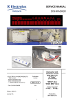
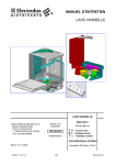
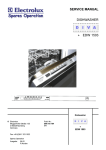
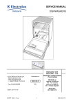
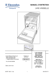
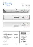
SERVICE MANUAL DISHWASHERS DISHWASHER ELECTROLUX ZANUSSI S.p.A. Spares Operations Italy Corso Lino Zanussi,30 I - 33080 PORCIA /PN (ITALY) Fax +39 0434 394096 Publication number 599 38 72-30 DIVA F. S. - Free-standing B. I. - Partially integrated F. I. - Fully integrated EN Basic characteristics Edition: 2007.03 Production: ZM Solaro_ITALY SOI/TD - PR 1/32 599 38 72-30 SOI/TD - PR 2/32 599 38 72-30 TABLE OF CONTENTS 1 2 3 4 5 6 7 INTRODUCTION ........................................................................................................................................................4 1.1 PURPOSE OF THIS SERVICE MANUAL ............................................................................................................4 1.2 PRESENTATION..................................................................................................................................................5 1.3 GENERAL CHARACTERISTICS..........................................................................................................................6 1.4 FIELD OF APPLICATION .....................................................................................................................................6 1.5 ELECTRONIC MODULE ......................................................................................................................................6 1.6 DEFINITION OF STYLINGS AND FUNCTIONS ..................................................................................................7 1.7 STRUCTURAL CHARACTERISTICS.................................................................................................................11 STRUCTURAL CHARACTERISTICS .......................................................................................................................12 2.1 BASE ..................................................................................................................................................................12 2.2 DOOR .................................................................................................................................................................12 2.3 TUB ....................................................................................................................................................................14 2.4 HYDRAULIC SYSTEM .......................................................................................................................................15 HYDRAULIC AND FUNCTIONAL CHARACTERISTICS ..........................................................................................16 3.1 WATER FILL TANK ............................................................................................................................................17 3.2 WATER SOFTENING SYSTEM .........................................................................................................................17 3.3 SUMP ASSEMBLY .............................................................................................................................................18 3.4 DRYING DUCT...................................................................................................................................................18 ELECTRICAL COMPONENTS .................................................................................................................................19 4.1 TERMINAL BLOCK ............................................................................................................................................19 4.2 PUSHBUTTON ...................................................................................................................................................19 4.3 TIMER ................................................................................................................................................................19 4.4 LATCH ASSEMBLY............................................................................................................................................19 4.5 WASHING PUMP ...............................................................................................................................................20 4.6 CAPACITOR.......................................................................................................................................................20 4.7 DRAIN PUMP .....................................................................................................................................................20 4.8 FILL SOLENOID VALVE ....................................................................................................................................20 4.9 TUBE-ENCASED HEATING ELEMENT.............................................................................................................21 4.10 TEMPERATURE THERMOSTAT ......................................................................................................................21 4.11 TEMPERATURE SENSOR.................................................................................................................................21 4.12 TEMPERATURE SENSOR + TURBIDITY SENSOR..........................................................................................21 4.13 INTEGRATED DISPENSER ...............................................................................................................................22 4.14 LEVEL & ANTI-OVERFLOW PRESSURE SWITCH...........................................................................................22 4.15 ANTI-FLOODING DEVICE .................................................................................................................................22 WASHING SYSTEM .................................................................................................................................................23 5.1 DEFINITION OF THE WASHING CYCLE ..........................................................................................................23 HYDRAULIC CIRCUIT..............................................................................................................................................24 6.1 PATH OF WATER INTAKE - "SHORT TANK"....................................................................................................24 6.2 PATH OF WATER INTAKE - "LONG TANK" ......................................................................................................25 6.3 WATER FILL SYSTEM - FUNCTIONAL DESCRIPTION ...................................................................................26 6.4 ANTI-OVERFLOW SAFETY LEVEL...................................................................................................................26 6.5 WATER SOFTENING SYSTEM .........................................................................................................................27 6.6 DEFINITION OF THE REGENERATION SYSTEM ............................................................................................29 DEFINITION OF THE DRYING CIRCUIT .................................................................................................................30 7.1 "NORMAL - DRY" DRYING ................................................................................................................................30 7.2 "ACTIVE - DRY" DRYING...................................................................................................................................31 7.3 "TURBO - DRY" DRYING SYSTEM ...................................................................................................................32 SOI/TD - PR 3/32 599 38 72-30 1 1.1 INTRODUCTION PURPOSE OF THIS SERVICE MANUAL The purpose of this Service Manual is to provide Service Engineers, who already have the basic knowledge necessary to repair household dishwashers, with information of a general nature regarding the new "DIVA" range of dishwashers. The aspects described in this document relative to the structural and hydraulic characteristics and the basic circuits are common to all the appliances in the range, both with electromechanical and electronic control systems. More detailed information regarding individual models may be found in the specific information documents for each specific functionality. This information covers: Technical characteristics Circuit diagrams Exploded diagrams and Lists of spare parts may be found in the Service Notes and Service Manuals issued separately for each specific model SOI/TD - PR 4/32 599 38 72-30 1.2 PRESENTATION NEW TECHNOLOGY: DISHWASHERS CREATED WITH COMPUTER-AIDED DESIGN SYSTEMS AND BUILT USING MODERN INDUSTRIAL TECHNOLOGY. RESULT: Drawing on our vast experience and resources, combined with the latest technical and structural techniques, we have produced this range of innovative appliances to meet the demands of a market that is constantly evolving. 1.2.1 MAIN CHARACTERISTICS 1.2.1.1 1.2.1.2 - 1.2.1.3 STRUCTURAL CHARACTERISTICS: Modular and convertible, in three versions: Free-standing, Partially built-in, Fully built-in Monobloc load-bearing base in sound-absorbing plastic material. Two removable side panels. Styling variable to meet the various configurations requested. Simplification of free-standing and built-in installation. On built-in models, the rear foot can be adjusted from the front of the appliance. HYDRAULIC CHARACTERISTICS: Newly-designed integrated hydraulic circuit. New integrated sump. New water softening system (if featured). Softening of regeneration water up to 90°F - 50°D (if featured). Optimization of the regeneration system with 5 to 10 levels of regeneration (if featured). Manual regulation of the regeneration level, if featured, on electromechanical models, software regulation for electronic models. ELECTRICAL CHARACTERISTICS: - New washing pump motor. New drain pump motor. New types of timer. New types of electronic boards (PCB). 1.2.1.4 CONTROL AND SAFETY SYSTEMS: 1.2.1.5 1.2.1.6 Measurement of water temperature by means of thermostats or temperature sensors for electronic models. Measurement of water fill level by means of a pressure switch. Anti-overflow safety system using a pressure switch. Anti-leakage safety system using an anti-flooding device. Protection against overheating using a safety thermostat (software for electronic models). Electrical door aperture safety system. Functional protection with constant monitoring (with software control for electronic models). SOUND-PROOFING: Improved silence thanks to the use of new materials and new construction technologies. SERVICE: - Easier access to components thanks to careful positioning, from the two removable side panels and from the frontal plinth. Electronic models: - Facilitation of repairs using diagnostics tests and trouble-shooting procedures. - The washing parameters can be modified to improve washing performance. SOI/TD - PR 5/32 599 38 72-30 1.3 GENERAL CHARACTERISTICS Power supply ⇒ 230 V / 50 Hz (limits 187−254 V) Total power absorption ⇒ 2300 W (with 2100 W heating element) Water supply ⇒ Min. / Max. Pressures: 5 − 80 N/cm Load capacity ⇒ 9 place settings for 45cm and 12 place settings for 60cm Noise level ⇒ ⇒ db 50 / 56 (A) sound pressure (electromechanical) db 46 / 50 (A) sound pressure (electronic) Class ⇒ [AAA] - [AAB] (electronic models) 2 * Declared consumption [BIO AAB programmes] - Water - Energy - Duration of cycle ⇒ 14Lt. - 1,10 KWh - 150 Min * Example of programme declared to the various consumer institutes (electronic models). 1.4 FIELD OF APPLICATION Washing system ⇒ ⇒ CONTINUOUS (electromechanical) CONTINUOUS /IMPULSE OPERATION (electronic) Control system ⇒ ⇒ TIMER (electromechanical) CONTROL BOARD (electronic) Water fill level ⇒ ⇒ PRESSURE SWITCH CONTROL (electromechanical) PRESSURE SWITCH+SOFTWARE CONTROL (electronic) Water heating ⇒ HEATING ELEMENT IN PROTECTIVE TUBE Temperature control ⇒ ⇒ THERMOSTATS (electromechanical) NTC TEMPERATURE SENSOR (electronic) Drying system ⇒ ⇒ ⇒ NORMAL DRY (electromechanical) ACTIVE DRY (electronic) TURBO DRY (electronic) Safety systems ⇒ ⇒ HYDRAULIC/ELECTRICAL SYSTEMS (electromechanical) TOTAL PROTECTION: HYDRAULIC/ELECTRICAL + SOFTWARE (electronic) Alarms ⇒ SOFTWARE SYSTEM WITH VISUAL DISPLAY (electronic) 1.5 ELECTRONIC MODULE Power board ⇒ MAIN OPERATIONAL CONTROL (built-in microprocessor) Comandi / Visualizzazione ⇒ USER-MACHINE INTERFACE SOI/TD - PR 6/32 599 38 72-30 1.6 DEFINITION OF STYLINGS AND FUNCTIONS 1.6.1 Control panel: - DIVA_ ELM [electromechanical] Option key On/Off key • Structure Function Type of control Programmes FreeStanding / Built- in Electromechanical On/Off key 1 > 3_keys + knob 3 > 6_progr. Control panel: - DIVA_ EDW500 EDW500 DEFINITION OF FUNCTIONS 1.6.3 • Programme selector knob DEFINITION OF FUNCTIONS 1.6.2 • Salt level indicator Structure Function Type of control Programmes Free- Standing / Built- in EDW_500 1 > 2_keys + knob also as ON/OFF 3 > 5_progr. Control panel: - DIVA_ EDW503 EDW503 DEFINITION OF FUNCTIONS SOI/TD - PR Structure Function Type of control Programmes Free- Standing / Built- in EDW_503 On/Off key 1 > 2_keys 3 > 5_progr. 7/32 599 38 72-30 1.6.4 Control panel: - DIVA_ EDW1001EDW1001-EDW1100EDW1100-EDW1110 Control panel versions • DEFINITION OF FUNCTIONS 1.6.5 • HORIZONTAL VERTICAL Structure Function Type of control Programmes Free- Standing / Built- in EDW_1001 EDW_1100 EDW_1110 On/Off key 3 > 6_keys / leds 3 > 6_ progr. Control panel: - DIVA_ EDW1003 DEFINITION OF FUNCTIONS Structure Fully integrated 1.6.6 Type of control Programmes EDW_1003 On/Off key 3 > 6_keys / leds 3 > 6_ progr. Control panel: - DIVA_ EDW1500EDW1500-EDW1510 Control panel versions • Function HORIZONTAL VERTICAL DEFINITION OF FUNCTIONS SOI/TD - PR Structure Function Type of control Free- Standing / Built- in EDW_1500 EDW_1510 3 > 6_ keys / leds Programmes On/Off key 3 > 6_ progr. + display 8/32 599 38 72-30 1.6.7 • Control panel: - DIVA_ EDW1503 DEFINITION OF FUNCTIONS Structure Function Type of control EDW_1503 3 > 6_ keys / leds Programmes On/Off key Fully integrated 3 > 6_ progr. + display 1.6.8 • DEFINITION OF FUNCTIONS 1.6.9 • Control panel: - DIVA_ EDW2000 Structure Function Type of control Programmes Free- Standing / Built- in EDW_2000 On/Off key 9_ keys / leds + display 6_ progr. Control panel: - DIVA_ EDW2003 EDW2003 DEFINITION OF FUNCTIONS Structure Free- Standing / Built- in SOI/TD - PR Function Type of control Programmes EDW_2003 On/Off key 7_ keys / leds + display 6_ progr. 9/32 599 38 72-30 1.6.10 Control panel: - DIVA_ EDW25 EDW2500 • DEFINITION OF FUNCTIONS Structure Function Type of control Programmes Free- Standing / Built- in EDW_2500 On/Off key 11_ keys / leds + LCD 6_ progr. 1.6.11 Control panel: - DIVA_ EDW25 EDW2503 • DEFINITION OF FUNCTIONS Structure Function Type of control Programmes Free- Standing / Built- in EDW_2503 On/Off key 4_ keys / leds + LCD 6_ progr. 1.6.12 Control panel: - DIVA_ EDW2000 VISI • DEFINITION OF FUNCTIONS SOI/TD - PR Structure Function Type of control Programmes Free- Standing / Built- in EDW_2000 VISI On/Off key 3_ keys / leds 4_ progr. 10/32 599 38 72-30 1.7 STRUCTURAL CHARACTERISTICS This convertible modular dishwasher is designed for maximum flexibility, and can be installed in the FREE-STANDING or BUILT-IN versions. Structure Version Version MODULAR FREE-STANDING BUILT-IN By removing the work top, the dishwasher can be inserted beneath a sink or a preexisting work-top in marble or wood, on condition that the dimensions of the compartment are as shown in the figure. This type of dishwasher is designed for installation beneath a sink or a pre-existing work-top in marble or wood, on condition that the dimensions of the compartment are as shown in the figure. The feet can be adjusted to a maximum of 80 mm. The rear foot is adjusted from the front of the appliance. 1.7.1 INTERNAL CHARACTERISTICS 1. 2. 3. 4. 5. 6. 7. 8. 9. 10. 11. 12. Upper basket guide Water softening level selector (if featured) Salt container cap (if featured) Detergent/rinse-aid dispenser Control panel Serial number plate Central filter (drain) Main filter (washing) Lower spray arm Upper spray arm Upper basket Work-top (free-standing versions only) SOI/TD - PR 11/32 599 38 72-30 2 STRUCTURAL CHARACTERISTICS The appliance consists of four main assemblies: - BASE - DOOR - TUB - HYDRAULIC SYSTEM These four assemblies are enclosed in a cabinet designed with the following removable parts: - Front panel (secured by two screws) - Two side panels (secured by six screws) - A work-top (free-standing versions only) secured to the structure by two screws at the rear. 2.1 BASE The specially-shaped base is moulded in sound-absorbing plastic material. - The base, which supports the body of the appliance, is fixed structurally to the tub. The following components are located in the base - The fill valve - The integrated terminal block, power cable and anti-interference capacitor - The washing pump capacitor - The anti-flooding device, if featured - The support system (rubber support blocks) for the washing pump - The counterweight (free-standing versions only, if featured) 2.2 DOOR The door consists of the following sub-assemblies: 2.2.1 CONTROL PANEL The control panel is in moulded plastic, and is secured to the inner door by six self-tapping screws. The control panel may be customized for the various stylings, with different colours and silk-screened markings, or by the application of a transparent or stainless steel panel mask. The following components are screwed or pressure-fitted to the inside of the control panel: - The timer or electronic board - The door aperture handle - The pushbutton array - The pilot lamp diffusers. 2.2.2 INNER DOOR The inner door is in and is secured by two lateral hinges (using four screws), which are secured to the two front uprights of the tub. The following components are fitted to the interior of the inner door: - The door latch with a built-in door aperture microswitch - The integrated dispenser (detergent and rinse-aid) - In the lower section, a seal with the bottom of the tub. 2.2.3 DOOR The door is in enamelled sheet steel, and is secured to the inner door by six screws around the perimeter and two lateral screws. - On certain stylings (free-standing) a perimetral surround is fitted for application of a front décor panel. - The doors of built-in appliances have holes, slots and shaped sections for application of an outer door in wood. SOI/TD - PR 12/32 599 38 72-30 2.2.4 DOOR HINGE In galvanized pressed steel, with a series of mechanisms (springs, levers, spindles) which form the system of movement for aperture/closure of the door. - Secured externally to the two lateral uprights (D) by pressure-fitted couplings and screws with metric thread. - Hinges with different functional characteristics and settings are used, depending on the styling of the appliance. 2.2.4.1 CHARACTERISTICS & FUNCTIONS Aperture and closure of the door is by means of a pair of self-adjusting hinges (A) and a tensioning spring (B). The movement is self-balancing and features an automatic "braking" system. The self-balancing system consists of a helical spring which is calibrated to a fixed setting. - The calibration depends on the overall weight of the door fitted to the appliance. - The helical spring is secured to the upper extremity of the upright and to the hinge mechanism. The automatic "braking" system consists of a mechanical clutch. - The clutch consists of a sliding element (C) fitted to the hinge mechanism which, during aperture and closure of the door, slides vertically along the surface of the hinge. - Some hinges are fitted with a double clutch system (two sliding elements) in order to provide a greater "braking" effect, so that doors of greater weight are balanced in the same way. SOI/TD - PR 13/32 B C D A 599 38 72-30 2.3 TUB The tub assembly consists essentially of a stainless steel tub and a series of sub-assemblies which form the load-bearing structure of the dishwasher. Two basic tubs have been designed, to suit the type of drying to be performed by the dishwasher. - The difference between the two lies in the presence or absence of a hole (*) in the rear section of the tub ceiling, to which the drying duct can be fitted. - Other differences concern the type of soundproofing, which depends on the number and thickness of the tar-coated panels. 2.3.1 STRUCTURAL CHARACTERISTICS The tub is produced by press-forming using steel. - Side and rear panels produced in a single production cycle (pressing, drilling, forming) Tub ceiling (pressing, drilling). Tub bottom (pressing, drilling). The side and rear panels are then crimped to the ceiling and the bottom of the tub. A silicone-based adhesive is inserted between the parts to provide a seal. Two ducts in stainless steel (in the shape of an inverted "L"), welded around the internal perimeter of the front section of the tub to the ceiling and the two sides, are used as a seat for the perimetral door seal. The tub is soundproofed by applying tar-coated panels, which are hot-glued on the external sides (all or some of the sides). These panels are of different thicknesses, according to the level of noise generated by the appliance. 2.3.2 STRUCTURAL SUB-ASSEMBLIES The structure of the tub is completed by the installation of a number of additional components C B * Lateral uprights (A), which support the tub on all four sides. Three of these (the two rear uprights and the RH lateral upright) are inserted into the base. - Two rear uprights, produced automatically using the "clinching" system (cold deformation welding). - Two front uprights, secured manually using three screws. Rear cross-member (B), in plastic, secured to the lateral uprights by two screws. - The rear cross-member is a structural support for the side panels and work-top, and also supports the various hoses. Front cross-member (C) in enamelled sheet metal, pressurefitted to the two lateral uprights and secured using two screws. - The front cross-member is a structural support for the side panels and work-top, and also for the door closure mechanism. 2.3.2.1 A COMPONENTS BUILT INTO THE TUB The tub is then fitted with a number of functional components. Externally: - On either side, the four supports for the upper basket guides. - On the RH side, the vertical manifold which ducts water to the upper spray arm. - On the LH side, the water fill tank. - On the upper side, the drying duct and (if featured) the fan. - On the bottom, the sump assembly and the water softening system, if featured. Internally: - On either side, the two guides in which the upper basket slides. - At the rear, the horizontal manifold which ducts water to the upper spray arm. SOI/TD - PR 14/32 599 38 72-30 2.4 HYDRAULIC SYSTEM The hydraulic system is common to all versions of the dishwasher, since its specific water softening function consists of a number of specific components. The only difference is the featuring or not of the water softening system. 2.4.1 HYDRAULIC PATH WATER INTAKE HOSE - Water intake from the mains supply circuit. FILL TANK - Passage of water into and out of the appliance. - Water deposit for regeneration, if featured. SOFTENING SYSTEM (if featured) - Passage of water for softening process. - Passage of water for regeneration process. SUMP - Collects water for the washing process and deposits for drainage. FILTER GROUP - Filters the washing water in circulation and retains any dirt. LOWER SPRAY ARM DUCT - Ducts water to the lower basket. UPPER SPRAY ARM - Ducts water to the upper basket. 2.4.2 DIFFERENCES IN THE HYDRAULIC CIRCUIT ACCORDING TO THE TYPE OF DRYING SYSTEM Although the functional principle of the hydraulic system is identical for all versions, the single exception is the fill tank, which differs according to the type of drying system. ACTIVE & ACTIVE TURBO TRADITIONAL Drying duct Short tank SOI/TD - PR Long tank 15/32 599 38 72-30 3 HYDRAULIC AND FUNCTIONAL CHARACTERISTICS SHORT TANK Fill tank LONG TANK Turbo fan Drying duct Fill tank + Condenser Counter-weight (if featured) Base Heating element Washing pump Softener (if featured) SOI/TD - PR Sump Drain pump 16/32 599 38 72-30 3.1 WATER FILL TANK The water fill tank is a container in transparent moulded plastic consisting of two sections that are welded together. - Inside the tank, special chambers and ducts define the path taken by the water during the fill phase. - The fill tank is positioned in the left-hand section of the appliance, and is screwed into position from inside the tub using a fixing ring. - The softener regulation system, if featured, is built into the fixing ring, and is actioned by a knob. The water fill tank is one of the main functional parts of the hydraulic circuit. D E LONG A TYPES OF TANK SHORT KEY A B C D E Water fill chamber and regeneration volume Regulation system for softening circuit Steam venting chamber Steam circulation chamber Steam condensation chamber B C A B The following functions are involved: SYSTEM OF FILL WATER INTAKE TREATMENT SYSTEM FOR REGENERATION WATER CONDENSATION OF STEAM 3.2 WATER SOFTENING SYSTEM (if featured) If featured, the water softening system consists of a monobloc container in transparent plastic. The container is subdivided into two sections, which communicate through internal ducts and contain the salt and the resin. The container is positioned in the base of the appliance and screwed to the tub from the inside by a fixing ring. - The container is connected to the water fill tank by two O-ring connectors. - It is also connected to the sump by an outlet duct. B A The following components are fitted externally to the container: - The salt sensor (A) - The regeneration solenoid valve (B) A normally-closed separation valve (*) is installed inside the container, and serves to separate the two sections: - The valve opens as a result of the pressure exerted by the water during the regeneration process, when the regeneration solenoid valve (4) opens. * SALT reservoir The salt reservoir contains the salt used for regeneration, and is accessible for filling. The salt sensor (A) indicates to the user that the salt reservoir requires topping up. The sensor consists of a reed sensor positioned externally to the reservoir, and a magnetic float inside the reservoir. The sensor is connected electrically to the SALT LED on the control panel in versions with electromechanical control; in electronic versions, it is connected directly to the PCB. RESIN reservoir This sealed reservoir contains the resins (organic substances used to purify the water). The regeneration solenoid valve (B), when actioned, performs the regeneration process (cleaning of the resins) SOI/TD - PR 17/32 599 38 72-30 3.3 SUMP ASSEMBLY The sump is a monobloc container in plastic material, and consists of three thermowelded sections: PRESSURE, WASHING and DRAIN. The sump is located on the bottom of the tub, with a perimetral sealing ring, and is secured from the inside by four screws. PRESSURE section (A) An integral part of the WASHING section, in which a double pressure chamber controls the level of the water. WASHING section (B) Located beneath the main stainless steel filter, this section collects the filtered water, which is then re-introduced (clean) into the circuit and ducted to the spray arms. - Direct hydraulic connection to the lower spray arm. A B C DRAIN section (C) Located beneath the circular filter in the bottom of the sump, where the dirt is deposited before being drained. - Housing for the drain filter. Four ball valves built into the sump perform a number of specific functions. Pressure switch pressure valves (2): - Positioned inside the respective pressure chambers. - In case of tilting of the appliance, the valves prevent the residual water in the sump from entering the connections of the two pressure switch tubes. Drain pump breather valve: - This valve is located internally, near the drain pump breather. - During the water fill phase, the valve opens and maintains the drain circuit open so that the air is expelled. This enables the pump to fill with water and prevents cavitation. Sump bottom valve: - Located internally, near the sump bottom. - During the water fill phase, the valve closes to separate the drain section from the washing section. - During the drain phase, the valve opens, thus connecting the drain and washing sections. The following connections are located externally: - Hydraulic connection to the softener via a rubber hose - Hydraulic connection to the drain pump, via a rubber coupling - Hydraulic connection to the washing pump, via a rubber coupling - Housing for the thermostat or temperature/turbidity sensor - To the level and safety pressure switches, via two small tubes of different colours. 3.4 DRYING DUCT The drying duct is a moulded plastic container consisting of two sections which are pressure-fitted together. The drying duct is used in Active and Turbo drying. During the drying phase, the function of the duct is to transfer the steam from inside the tub into the fill tank condenser, where it is condensed. The drying duct is positioned externally above the tub and fixed from the inside by a snap ring. 3.4.1 DRYING DUCT + FAN Turbo drying is obtained by means of a fan located inside the drying duct. The fan consists of a small synchronous electric motor and an elastic drive belt which actions the suction fan blade. When the fan is in operation, it creates a forced air movement. SOI/TD - PR 18/32 599 38 72-30 4 ELECTRICAL COMPONENTS 4.1 TERMINAL BLOCK The terminal block consists of a junction box to which the power cable is connected; the wiring is then routed to the appliance's ON/OFF switch. The terminal block is pressure-fitted into a housing inside the base. A suppressor is built into the terminal block. The suppressor is an electrical device designed to filter out radio interference. Correct operation of the suppressor requires that the appliance be connected to an efficient ground connection. 4.2 PUSHBUTTON The pushbutton array consists of one or more modular buttons (maximum 4) in a single block (the individual buttons are pressurefitted into a metal support). The pushbutton array is located inside the control panel and secured by two screws. The pushbuttons are of two types, with different functions: - Switch (two-pole) for the ON/OFF key - Deviator (single-pole/two-pole) for the Option keys. 4.3 TIMER The timer is a timer-controlled electrical device which controls the duration and the execution of the operations that comprise the washing cycle. All the "user" components (solenoid valve, pump, heating element etc.) are connected electrically to the timer by means of a specific wiring harness. The signals to the user components are transmitted via the contacts (switching) fitted to a lateral support and actioned by a series of cammes. The movement of the cammes is transmitted by a synchronous motor via a series of levers and gears which, in turn, advance the timer from one step to the next. One complete rotation of the timer is subdivided into 58 steps, each with a specific duration (step time variable between 5 sec and 24 sec). 4.4 LATCH ASSEMBLY Closure of the door is performed by a mechanical locking/release system which also connects and disconnects the electrical components in the appliance. The latch is positioned inside the inner door in the upper section, and is secured from the exterior by two screws. The assembly consists of the latch, which also features a built-in microswitch. Latch: The latch is in plastic material in which a system of levers provides the mechanical action. Microswitch: The microswitch is connected electrically (in series) to the ON/OFF switch, and opens or closes the contacts in order to connect or disconnect the machine from the power supply. The microswitch is pressure-fitted into a housing in the latch. SOI/TD - PR 19/32 599 38 72-30 4.5 WASHING PUMP Single-phase asynchronous two-pole motor with a single direction of rotation. - Counter-clockwise rotation (seen from impeller side). - The hydraulic group (pump scroll casing, sealing rings and impeller) is clamped to the motor shield, with an internal sealing ring. - Secured to the base of the appliance by two supports in vibration-damping rubber. - Connected to the sump by rubber couplings. 4.5.1 WASHING PUMP (versions with Electronic control) Same functional characteristics, but with one exception: The pump is fitted with a tachymetric sensor (G) housed externally to the motor. The sensor is connected to the electronic control system in order to provide variable speeds of rotation. 4.6 117 Ω 48 Ω 213 Ω CAPACITOR Capacitance 3µF - operating voltage 450 V. The capacitor is permanently connected to the windings of the washing pump, and is used to start up and maintain rotation in all operating conditions. 4.7 DRAIN PUMP Single-phase two-pole synchronous centrifugal motor. - Rotation in both directions. - Integrated hydraulic group (pump body and impeller). - Secured to the sump by snap-on connectors and connected hydraulically via a rubber coupling. - A diaphragm-type non-return valve (A) positioned on the outlet coupling reduces the quantity of water remaining in the sump at the end of the drain cycle and prevents water from entering the appliance from the drain system (in the sink). 4.8 A FILL SOLENOID VALVE Traditional single-coil solenoid valve with one inlet and one outlet. - Positioned in the lower rear section of the base. - The outlet is connected via a tube to the water fill tank. - Rated delivery 4 litres/min. approx. 4.8.1 "AQUACONTROL" FILL SOLENOID VALVE Integrated single-coil solenoid valve fitted upstream of the fill hose. - The fill hose is coupled from the outlet in the lower rear section of the base to the water fill tank. - Rated delivery 4 litres/min. approx. SOI/TD - PR 20/32 599 38 72-30 4.9 TUBE-ENCASED HEATING ELEMENT The heating element, which is encased inside a tube, is used to heat the washing water. The heating element is not activated during the drying phase. - Inserted into the delivery side of the washing pump and coupled with the duct which directs water to the upper spray arm. - Standard version for all the appliances in the range. - Heating power: 2,100 Watts. Built-in safety devices: - 1 auto-reset bi-metal thermostat calibrated to 98°C and connected in series to one branch of the heating element. - 1 manual-reset fuse calibrated to 206°C and connected in series to the second branch of the heating element. If this fuse intervenes, the heating element is disconnected definitively. 4.10 TEMPERATURE THERMOSTAT Used in versions with electromechanical control systems (timers) to control the temperature of the washing water. - Positioned externally on the sump, in direct contact with the water. Available in two versions: with one temperature or two temperatures. - 1_Tº for appliances with fixed-temperature washing (65°C). - 2_Tº for appliances with variable-temperature washing (50 ÷ 65°C). 4.11 TEMPERATURE SENSOR Used in versions with electronic control systems to control the temperatures of the washing water. - Positioned externally on the sump, in direct contact with the water. - Constantly transmits the temperature of the water to the electronic control system. - Consists of an NTC sensor whose resistive value decreases as the temperature of the water increases. 4.12 TEMPERATURE SENSOR + TURBIDITY SENSOR If featured, it’s used in versions with electronic control (high-end appliances) to control both the temperature and the turbidity of the washing water. - Positioned externally on the sump in direct contact with the water. - Fitted with an NTC sensor for control of the temperature. - Fitted with an infra-red system for control of the turbidity of the water (i.e. the quantity of dirt in the water). - Constantly transmits the two signals to the electronic control system for processing. - By correctly combining the signals received from the two sensors (NTC and turbidity), enables the appliance to perform "automatic" washing cycles which automatically optimize the washing cycle according to the type of load, the quantity of the load and the degree of soiling. 4.12.1.1 TURBIDITY DETECTION SYSTEM This consists of a reading process which takes place during the cycle according to the signals received from the turbidity sensor by the electronic control system. The signal is transmitted by the sensor and enables the control system to identify the status of the cycle. 1st reading during Pre-wash phase:- Determines whether the pre-wash drain cycle is performed. If the drain cycle is performed, the wash phase is performed at the normal temperature (65ºC). If the drain cycle is not performed, the wash phase is performed at 50ºC. 2nd reading during the 1st rinse:- Determines whether the 2nd rinse is performed.. SOI/TD - PR 21/32 599 38 72-30 4.13 INTEGRATED DISPENSER The integrated dispenser consists of a plastic container comprising B two separate sections which contain Detergent (A) and Rinse-aid (B). A - Fitted to the interior of the inner door and secured by two screws. - The dispenser uses a single electrical coil connected to a mechanical system and which performs both functions. - When the coil is energized, it actions the mechanism via a series of levers, thus introducing the contents in sequence (first detergent, then rinse-aid). - The dispenser is controlled by the timer (or PCB) at predetermined steps during the cycle to ensure correct dosing. - A window to the side of the rinse-aid sector indicates the level of detergent (when the window is clear, the detergent requires topping up). 4.14 LEVEL & ANTI-OVERFLOW PRESSURE SWITCH These are two traditional pressure switches (pneumatic diaphragm type) connected to a special support which is in turn secured to the right-hand upright by two screws. 4.14.1 LEVEL PRESSURE SWITCH Determines the level of water introduced into the appliance. Operating range: Intervention/Reset = 65/ 45mm Operating characteristics: Empty/Full = Contacts 1-2 / 1-3 4.14.2 ANTI-OVERFLOW PRESSURE SWITCH Ensures that the level of water in the appliance does not exceed the safety threshold (overflow from the door). Operating range: Intervention/Reset 129/ 105mm Operating contacts: Empty/Full = Contacts = 1−2 / 1−3 - Connected electrically in series via contacts 1-3 to the drain pump. - If the switch intervenes on Full (1-3), the drain pump switches on until the switch returns to Empty (1-2) 4.15 ANTI-FLOODING DEVICE This mechanical/electrical safety device is activated if water is detected in the bottom of the appliance, if featured. The device consists of a plastic container which contains a sensor (floating type) and a microswitch. It is fitted into a special housing inside the base of the appliance. Sensor (A): - Extra-light polystyrene sensor whose position (at rest or raised) determines the mechanical action of the microswitch. B A Microswitch (B): - This switch is connected in series to the fill solenoid, and opens or closes the contacts in order to connect or disconnect the solenoid valve electrically. - When at rest (solenoid valve energized), the electrical contacts are closed. - Fitted into a housing in the container. SOI/TD - PR 22/32 599 38 72-30 5 WASHING SYSTEM The washing system is of the traditional type in which the mechanical washing action is provided by the rotation of the washing pump. The pump ducts the water into the hydraulic circuit, thus actioning both spray arms simultaneously. In order to obtain the washing result, the system also requires features such as heating of the water, change of the water, introduction of detergent and rinse-aid etc.. All these functions are included in the washing cycle. 5.1 DEFINITION OF THE WASHING CYCLE The various washing cycles are known by commercial descriptions such as:- Vigorous, Normal, Short, etc. At design level, the cycles are based on a series of "washing phases" comprising Pre-wash, Wash, Rinses and Drying. Each of these phases includes a number of "phase cycles" which determine the execution of the washing cycle in a logical sequence. Each phase in the operation of the appliance has a pre-determined duration and temperature, though these can be modified using the supplementary keys to create different cycles. In other words, the functions performed during the washing cycle are variable according to the cycles defined. For further details regarding the definition of the washing cycles, refer to the specific Service Notes for each model. Basic progressive composition of the phases of the washing cycle WASHING PHASES PRE-WASH WASH 1st RINSE 2nd RINSE 3rd RINSE DRYING Phase cycles Fill/Drain Fill Washing Heating Drain Fill Washing Heating Drain Fill Washing Drain Fill Wash Drain Fill Wash Heating Drain Pause Fan Phase functions Complementary functions (*) Variable functions Resin washing Wait for pressure switch (0º > 50ºC) Wait for temperature Wait for pressure switch Detergent (50º > 65ºC) Wait for temperature Wait for pressure switch (skip phase) Wait for pressure switch Wait for pressure switch Wait for temperature Rinse-aid Regeneration (50º > 65ºC) (if featured) STOP (*) The variable functions are optional, and are controlled by supplementary keys or by direct wiring connections according to the requirements of the specific market. SOI/TD - PR 23/32 599 38 72-30 6 HYDRAULIC CIRCUIT 6.1 PATH OF WATER INTAKE - "SHORT TANK" From the solenoid valve (2/3), the water is ducted into the fill tank and across the air break (5) into the regeneration chamber (7) until the chamber is full. Once the chamber is full to overflowing, and the softener system is featured, the water is divided into two parts through two separate channels. - One channel ducts the water directly into the softening system (9) (resin container), from where the softened water continues towards the sump. - A smaller quantity of water is collected in one of the channels for use in the "Blending" function (refer to section 6.6 - "Definition of the Regeneration System"), where it is ducted directly into the tub through the steam venting ring. With Softener Without Softener KEY 1 - Fill hose 2 - Fill hose with "Aquacontrol" device 3 - Fill solenoid 4 - Regeneration solenoid 5 - Air-Break 6 - Steam condenser 7 - Regeneration chamber 8 - Salt reservoir 9 - Resin reservoir SOI/TD - PR 10 - Level pressure switch 11 - Anti-overflow pressure switch 12 - Sump assembly 13 - Washing pump 14 - Tube-enclosed heating element 15 - Drain pump 16 - Non-return valve 17 - Drain hose 18 - Anti-flooding device 24/32 599 38 72-30 6.2 PATH OF WATER INTAKE - "LONG TANK" From the solenoid valve (2/3), the water is ducted into the fill tank and across the air break (5) into the steam condenser (6) until the condenser is full. - When the condenser is full to overflowing, and the softener system is featured, the water is ducted through a channel into the regeneration chamber (7). In this case, too, once the overflow level is reached, the water is divided into two parts ducted through two separate channels. - Part of the water passes through one channel directly to the softener (9) (resin container), from which the softened water continues towards the sump. - A smaller quantity of water is collected in one of the channels for use in the "Blending" function (refer to section 6,6 - "Definition of the Regeneration System"), where it is ducted directly into the tub through the steam venting ring. N.B. - The steam condenser (6), once full of water, remains filled. With each subsequent fill, the incoming water replaces the water previously present in the condenser. The steam condenser (6) is drained through the fill hose (1/2) by a vacuum effect, after disconnecting it from the intake tap and laying it on the floor. With Softener Without Softener KEY 1 - Fill hose 2 - Fill hose with "Aquacontrol" device 3 - Fill solenoid 4 - Regeneration solenoid 5 - Air-Break 6 - Steam condenser 7 - Regeneration chamber 8 - Salt reservoir 9 - Resin reservoir 10 - Level pressure switch SOI/TD - PR 11 - Anti-overflow pressure switch 12 - Sump assembly 13 - Washing pump 14 - Tube-enclosed heating element 15 - Drain pump 16 - Non-return valve 17 - Drain hose 18 - Drying duct/Fan 19 - Anti-flooding device 25/32 599 38 72-30 6.3 WATER FILL SYSTEM - FUNCTIONAL DESCRIPTION In all versions of the dishwasher (electromechanical and electronic), the water fill system is constantly controlled by the level pressure switch, which acts as a pressure sensor. 6.3.1 DEFINITION OF WATER LEVEL The pressure switch is connected hydraulically to the sump, inside which an air trap (pressure chamber) is connected via a small tube in order to determine the level of water in the appliance. In the water level circuit, the air pressure is proportional to the quantity of water present in the sump. When this pressure exceeds the pre-determined threshold, the pressure switch (which acts as a pressure sensor) switches the electrical contact to "full". In order to maintain this condition, the stability of the water level is ensured during operation (washing), which maintains the pressure switch closed on "full". It is therefore possible to ascertain with certainty that the status of the pressure switch - i.e. its position of "empty" or "full" - ensures that the cycle is performed correctly. 6.4 ANTI-OVERFLOW SAFETY LEVEL In all dishwashers (electromechanical and electronic), the anti-overflow safety system is constantly monitored by the safety pressure switch (which acts as a pressure sensor) in order to prevent water from overflowing due to an excessively high level. - The safety pressure switch is connected pneumatically via a small tube to the sump, which contains a second pressure chamber (air trap), located adjacent to that of the level pressure switch. In the safety circuit, too, the air pressure is proportional to the quantity of water present in the sump. - Therefore, in case of a malfunction in the hydraulic circuit, and if the water level exceeds the predetermined safety threshold, the pressure switch intervenes by switching the electrical contact to "full". 6.4.1 INTERVENTION OF THE ANTI-OVERFLOW DEVICE The safety pressure switch commutates to "full", which immediately activates the drain pump, which is connected electrically downstream of the circuit; the pump remains in operation until the safety thermostat returns to "empty". Versions with electromechanical control The washing cycle continues in any case. - If the malfunction is caused by a temporary fault (leakage from the solenoid valve, excessive foam etc.) which ceases to exist during the cycle, the user is unlikely to be aware that the fault has occurred. - If the fault persists, water will remain in the tub at the end of the cycle, and the drain pump will switch on and off alternately, since it is controlled by the pressure switch (which cycles between "full" and "empty"). The connections for the anti-overflow system are shown in the diagram opposite. N.B. - If the appliance is switched off using the ON/OFF switch at the end of the cycle, the drain pump switches off. - In order to ensure that the anti-overflow safety device remains in operation even when the dishwasher is not in use, (1) the machine must remain connected to the power supply and (2) the ON/OFF switch must be set to ON. Versions with electronic control Important: - If at the end of the cycle the door is opened or the appliance is switched off, the drain pump will be disactivated. - To ensure that the anti-overflow device remains in operation, the appliance must remain connected to the power supply with the ON/OFF switch in the ON position and the door closed. N.B.:- For further details, refer to the Service Notes describing the functions of each specific model. SOI/TD - PR 26/32 599 38 72-30 6.5 WATER SOFTENING SYSTEM 6.5.1 SOFTENING PROCESS If featured, this softening system is based on the use of resins (organic synthesis substances) and a chemical process of ion exchange. This exchange takes place rapidly, i.e. as soon as the water comes into contact with the resins. The calcium and magnesium salts contained in the water are removed, while their sodium base is created. The exchange process takes place during every fill phase, each time water is introduced into the circuit by energizing the solenoid valve. 6.5.1.1 SOFTENING CIRCUIT The fill water from the solenoid valve (2/3), after filling the regeneration chamber (7), continues its path until it reaches the resin reservoir (9). The water then slowly passes upwards through the resin bed, where it is softened; from here, the water continues its route towards the sump. Obviously, after a certain period, the resins lose their softening power (i.e. are no longer able to perform the sodium exchange) because they are saturated with calcium and magnesium. In this case, it is necessary to regenerate the resins by introducing sodium chloride (salt). 6.5.2 REGENERATION PROCESS In order to regenerate the resins and restore their efficacy, it is necessary to use a salt (sodium chloride) solution, which should be allowed to pass slowly through the resins or, preferably, left to soak the resins for a period. In this case, too, the ion exchange takes place. The sodium contained in the salt solution eliminates the calcium and magnesium salts that have been deposited on the resins, which thus regain their softening power. The regeneration phase is performed at a pre-determined point in the washing cycle by energizing the regeneration solenoid valve for a given time. The quantities of water and salt used are optimized according to the level of regeneration selected by the user, which in turn depends on the hardness of the water coming from the mains. 6.5.2.1 REGENERATION CIRCUIT The volume of water utilized for the regeneration process depends on the degree of inclination of the separation baffle (A). The water is ducted through the separation baffle via an internal channel which is open at one extremity. The inclination of the separation baffle determines the quantity of water used: as the baffle moves towards the horizontal position, more water is used, since only the water above the overflow level is introduced. When the regeneration solenoid (4) is energized, the volume of water contained in the regeneration chamber (7) (280 cc max.) descends by gravity into the salt reservoir; at this point, the internal valve (*) opens, allowing the corresponding quantity of salty water to pass into the resin reservoir (9). After draining, the internal valve (*), which is no longer pressurized, closes the circuit. When the solenoid is de-energized, the salt solution remains in the resin reservoir until the subsequent resin washing procedure is performed. SOI/TD - PR 27/32 A * 599 38 72-30 6.5.3 WASHING THE RESINS On completion of the regeneration process, it is necessary to clean the softening circuit by washing the resins in order to remove any residual impurities. The water in the resin reservoir (9), which contains alkaline salts (calcium and magnesium) and sodium chloride, must be cleaned before the subsequent fill phase in order to ensure that it does not come into contact with the dishes or the internal parts of the appliance, since it is corrosive. In this case, too, the fill solenoid and the drain pump switch on simultaneously at a certain point in the cycle and for a pre-determined period, to circulate a quantity of water (about 2 litres) which flushes the softening circuit. 6.5.3.1 RESIN WASHING CIRCUIT During this phase, the two functions (fill and drain) are performed simultaneously. Fill solenoid [2/3] When the solenoid is energized, water is circulated through the resin reservoir (9) and from there to the sump (the circuit described in sections 4.1/4.2 "Path of the fill water" is repeated). Drain pump [15] When the drain pump is switched on, the water ducted to the bottom of the sump (12) is immediately drained as it arrives, without coming into contact with the dishes. 6.5.3.2 RESIN WASHING PROCEDURE In all versions of the dishwasher (electromechanical and electronic), the resin washing procedure (duration 30 seconds approx.) is performed at the beginning of each washing cycle. - In effect, the salty water solution (regeneration water) remains deposited in the resin reservoir from the end of the last cycle until the beginning of the subsequent cycle. SOI/TD - PR 28/32 599 38 72-30 6.6 DEFINITION OF THE REGENERATION SYSTEM In all versions of the dishwasher (electromechanical and electronic), regeneration of the softener (duration 3 minutes approx.) is performed towards the end of the cycle, during the drying phase. 6.6.1 “BLENDING” FUNCTION This function is performed inside the fill tank during the water fill phase which, depending on the position of the selector, automatically blends the softened water with the unsoftened water present in the appliance. - In practice, the softened water is introduced into the appliance through the softening system, while the unsoftened water flows via an open by-pass duct directly through the steam venting ring. - If the mains water supply is very soft, this function optimizes the hardness of the washing water in order to prevent the possibility of corrosion of glass recipients. - The quantity of unsoftened water that is introduced into the appliance is expressed as a percentage of the total quantity of water utilized. SELECTOR ON TANK “BLENDING” FUNCTION Position of selector 1 2 3÷5 Water blending 20 % 10 % -- 6.6.2 SELECTING THE LEVEL OF REGENERATION Electromechanical versions On electromechanical dishwashers, regeneration is performed during every washing cycle. The level of regeneration is selected using the selector located inside the tub (on the left-hand side, near the steam venting ring). - The quantity of water utilized depends on the position of the selector. - The knob can be set to one of ten different settings as shown in the table below. - If the selector is set to (L1) or (L2), the "Blending" function is performed automatically, thus blending softened water with unsoftened water. To select a different level of regeneration (according to the hardness of the mains water supply), open the door and adjust the position of the selector from inside the appliance as follows: - Turn the selector until the correct level (1 - 10) is aligned with the marker. - If the water is hard, turn the selector clockwise; if it is soft, turn the selector counter-clockwise. Selection of the appropriate level of regeneration will ensure efficient washing. TABLE OF REGENERATION LEVELS Set up of Softener Level 1 2 3 4 *5 6 7 8 9 10 Manual 1 1 1 1 2 2 2 2 2 2 Eletronichal 1 2 3 4 *5 6 7 8 9 10 Number of acoustics signal (if featured) 1 2 3 4 5 6 7 8 9 10 Water filled in between two regenerations litres --130 94 70 53 37 20 15 10 3 Opening of Regeneration solenoid sec 0 240 240 240 240 240 240 240 240 2x240 HARDNESS OF TREATED WATER º F (TH) 0>7 8 > 18 19 > 25 26 > 32 33 > 39 40 > 50 51 > 64 65 > 75 76 > 90 91 > 125 º D (dH) 0> 4 4 > 10 11 > 14 15 > 18 19 > 22 23 > 28 29 > 36 37 > 42 43 > 50 51 > 70 6.6.3 SELECTING THE LEVEL OF REGENERATION Electronic versions In electronic dishwashers, regeneration is performed as and when necessary. For further details regarding this process, refer to the "function" Service Manuals for these versions of the dishwasher. SOI/TD - PR 29/32 599 38 72-30 7 DEFINITION OF THE DRYING CIRCUIT In these dishwashers, the dishes are dried by means of a steam condensation process. Depending on the type of appliance, one of three drying systems is used: - "NORMAL - DRY" drying - "ACTIVE - DRY" drying - "TURBO - DRY" drying 7.1 "NORMAL - DRY" DRYING DEFINITION OF THE SYSTEM The "Normal Dry" system is characterized by an integrated circuit which draws in and expels air to the exterior of the appliance. - This is the classic, traditional drying system, based in the natural circulation of hot air. - The steam (hot, humid air) produced during the hot rinse enters from the lower section through the steam venting ring, and circulates slowly inside the chamber of the fill tank. Here, it is condensed and expelled from the upper section towards the exterior. SOI/TD - PR 30/32 599 38 72-30 7.2 "ACTIVE - DRY" DRYING DEFINITION OF THE SYSTEM The "Active Dry" system is characterized by an integrated closed circuit in which the hot air is circulated in a bi-directional convection movement onto a cold wall; no air is drawn in from the exterior. - This drying system is based on the natural circulation of the hot air produced during the hot rinse, where the steam (hot, humid air) circulates inside the condenser of the fill tank through two connector ducts, thus generating the process of condensation. - Part of the steam enters from the lower section through the steam venting ring and circulates slowly inside the chamber of the condenser. - The remaining part of the steam circulates in the same way, entering from the upper section of the tub through the external upper duct, which communicates with the chamber of the condenser. - The condenser is a condensation chamber filled with water (cold wall) against which the hot air is ducted. This contact between the hot air and the cold wall generates the process of condensation. This forms a closed condensation circuit which does not expel steam to the exterior, from which the circuit is isolated. The drying time is variable and pre-defined for each washing cycle. SOI/TD - PR 31/32 599 38 72-30 7.3 "TURBO - DRY" DRYING SYSTEM The "Turbo Dry" system is characterized by an integrated closed circuit in which the hot air is circulated in a mono-directional convection movement onto a cold wall; no air is drawn in from the exterior. - This drying system is based on the forced circulation of the hot air produced during the hot rinse, where the steam (hot, humid air) is drawn in by the fan located inside the upper duct and then ducted towards the condenser in the fill tank, from where it returns to the tub via the steam venting ring. - The condenser is a condensation chamber filled with water (cold wall) against which the hot air is ducted. This contact between the hot air and the cold wall generates the process of condensation. - This forms a closed condensation circuit which does not expel steam to the exterior, from which the circuit is isolated. The fan is not switched on continuously, but pauses at intervals. The drying time is variable and pre-defined for each washing cycle. SOI/TD - PR 32/32 599 38 72-30