1
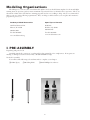
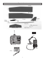
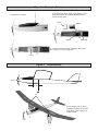
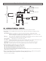
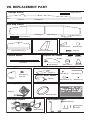
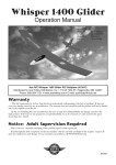
Whisper 1400 EP
Operation Manual
Specifications:
Wingspan:
55”(1400mm)
Length:
32.5”(825mm)
Wing area:
323 sq. in.
Weight:
1.3 lb.(600g)
Motor:
Speed 400
Power:
6V @ 600mAh
Ace R/C Whisper 1400 Electric Powered R/C Sailplane (4303-F)
Distributed by Ace Hobby Distributors, Inc. • 116 W 19th ST, Higginsville, MO 64037
Phone: 660-584-7121 • www.acehobby.com • E-mail: [email protected]
Warranty
This kit is guaranteed to be free from defects in material and workmanship at the date of purchase. It does not
cover any damage caused by use or modification. The warranty does not extend beyond the product itself and is limited
only to the original cost of the kit.
By the act of building this user-assembled kit, the user accepts all resulting lliability for damage caused by the
final product. If the buyer is not prepared to accept this liability, it can be returned new and unused to the place
of purchase for a refund.
Notice: Adult Supervision Required
This is not a toy. Assembly and flying of this product requires adult supervision.
Read through this book completely and become familiar with the assembly and flight of this airplane. Inspect all
parts for completeness and damage. If you encounter any problems, call 660-584-6724 for help.
JE6083
Modeling Organizations
The Whisper is a serious radio-controlled model aiplane and you should obtain airplane check-out and flight
training from an experience pilot to insure maximum enjoyment and success from the R/C experience. There are
thousands of clubs in the U.S. that have training programs and are very willing to help. Also, it is recommended
that you join one of the following organizations. They can help you find a club in your area plus offer insurance
programs to protect you.
Academy of Model Aeronautics
Sport Flyers of America
5151 East Memorial Dr.
POB 7993
Haledon, NJ 07508
Muncie, IN 47302
800-745-3597
800-435-9262
Fax 973-305-6686
Fax 765-741-0057
www.modelaircraft.org
www.modelaviation.com
I. PRE-ASSEMBLY
Unpacking and parts check:
Carefully unpack the contents of your kit and check it against Fig. 1 for completeness. If any parts are
missing or damaged, customers in USA may call 660-584-6724 for help.
Needed for assembly
You will need the following tools and materials to complete your whisper:
p 5-Min. Epoxy
p Modeling Knife
p Small Phillips Screwdriver
2
Figure 1.
Contents
Left Wing
Right Wing
Canopy
Fin/Rudder
Fuselage
Folding
Propeller
Wing Joiner
Rubber Band
Stabilizer/Elevator
Wing Protector
Velcro
Transmitter
Charger
Battery
3
II. Assembly
Follow the assembly steps. We have illustrated each
step and provided text to explain the process.
Main Wing Assembly
3. After the epoxy has
the wing joiner.
cured, draw a center line on
4.
Before gluing the two wing halves, dry-fit the wing
joiner into the slots in both the right and the left inner
wing halves. Sand if needed for good fit. (Note: the wing
is supposed to be joined at an angle; this angle is called
dihedral.) When satisfied, apply a thin coat of epoxy on
all sides of only one half of the wing joiner (see drawing).
Insert the glued
half of the wing
joiner into the slot
in the left wing
panel, stopping at
the center line.
Make sure you
wipe off any excess epoxy with a paper towel. Let cure.
1. Note that each wing panel is actually two pieces with
an inner section and a tip section. These two sections
for each wing panel are joined as follows. On the top of
the wing, carefully cut the covering away from between
the ribs where the inner and the outer panel join. Also
remove the small balsa wedge in-between the ribs. Put
a light coat of 5 min. epoxy in the resulting slot. Bend
the outer panel upward so the two ribs meet, forming
an angle that is called “dihedral”. Wipe off any excess
epoxy and hold in place while the glue sets.
5. Lightly coat epoxy on all sides of the other half of
the wing joiner (exposed part) and the exposed balsa
inner edges of both wing panels (called the wing root).
Slide the wing halves together, ensuring that they are
accurately aligned. Firmly press the halves together and
wipe off any excess epoxy. Let the epoxy cure while
holding the wing together in proper alignment.
2. Locate two dihedral plywood wing joiners. Glue two
wing joiners together with 5-minute Epoxy.
4
2.
6.
Remove the tail and VERY carefully use a sharp
hobby knife to cut the covering on the bottom of the
stabilizer about 1/16” on the INSIDE of the lines you just
traced onto the tail. Just score the covering film. DO
NOT cut into the wood or you will weaken the structure.
Carefully peel away the covering material in this area.
Attach the plastic wing protector onto the center of
the top of the wing, flush with the rear edge (trailing
edge). Use either epoxy or thin double sided tape to hold
it in place.
Rear
Elevator Servo
Front
7. Find the decal sheet and cut off a strip of material
where indicated. Dress up the three wing joints by
covering them with this material.
3.
TAIL ASSEMBLY
Second Hole
1.
Trial fit the stabilizer in place on the fuselage.
Center it on the fuselage; the elevator control horn
should be aligned with the centerline of the fuselage.
Use a felt-tip pen to trace where the fuselage sides meet
the bottom of the stabilizer.
Inside the fuselage’s wing
compartment, loosen the hex
screw that secures the elevator
pushrod on the elevator servo
horn. Pull this pushrod completely out of the fuselage.
Insert the “Z” bent end of the
pushrod into the second hole of the elevator control horn.
Then replace the pushrod in the rear of the fuselage,
sliding the assembly forward until the stabilizer is properly positioned. MAKE SURE you insert the pushrod
into its connector on the elevator servo horn as you move
5
the tail into position. Use 5 min. epoxy to glue the stabilizer
in place. It is important to keep the stabilizer level in
regards to the fuselage and the fin perpendicular to the
stabilizer while the glue cures. Also, make sure the elevator pushrod had stayed inserted into its connector on the
elevator servo horn.
4.
IMPORTANT: Before flying, you must turn the
radio on (with receiver battery charged and transmitter
batteries installed) and check that the elevator and rudder are in the neutral position with the transmitter
stick and trims in neutral. Securely tighten the hex
screw on the elevator pushrod connector on the elevator servo horn. Also, adjust the rudder pushrod if
needed.
Level with fuselage
Figure 2.
Charge the Batteries
MAINTAIN
POLARITY!
Red
Positive
Black
Negative
Knob
LED
12 Volt Battery
CAUTION:
• Maintain Polarity;
Red to + (positive)
Black to – (negative)
• Do not leave the battery
unattended while charging
• If battery pack gets hot,
disconnect and use
1. Hookup as shown
2. Turn charger knob
to 30
3. Make sure LED lights
4. Wait until charger clicks off (30 min.)
6
Figure
Figure2.3. Charge
Batterythe
Installation
Batteries
2. Remove the Foam, Plug in the Battery, then
place the Battery through the Bulkhead and
secure it with velcro.
1. Remove the canopy
Foam
Velcro
Velcro
Bulkhead
3. Place the Foam in front of Battery. Re-install
the canopy. You are ready to fly.
Foam
Figure 4.
Check Balance
Level
2 in.
(5 cm)
C.G.
If nose drops, tape a penny
to bottom fuselage at tail end.
If tail drops, tape a penny to
inside of cowl.
Level
7
Figure 5.
Airborne Radio Components
RECEIVER
ELEVATOR SERVO
RUDDER SERVO
AUTO CUTOFF SYSTEM
10A FUSE
MOTOR
NICD BATTERY
SWITCH
START BUTTON
III. OPERATIONAL CHECK
1. Install eight AA batteries in the transmitter, referring to the radio system’s instruction manual.
2. Review Fig. 5 to become familiar with your airborne radio components. Following are descriptions of these
components.
Auto Cut-off: This device cuts-off power to the motor unit when the battery’s voltage starts to drop.
This allows the battery to continue to power the radio for several minutes after the motor quits.
There is a 10 amp fuse which protects the system from overload.
Receiver:
Receives the radio commands from the transmitter and sends them to the Servos which converts the
command to motion which, in turn, moves the rudder or elevator.
Power Switch:
Turns the power on to the whole system.
Start Button: When pushed, this button starts the motor unit running. The motor will run until either the Power
Switch is turned off or the Auto Cut-off device cuts off power to the motor.
NiCd Battery:Rechargeable battery pack that provides power to the motor unit and the radio system.
Motor Unit:
Contains a DC electric motor and a propeller that provides the thrust for the airplane.
3. Turn the transmitter on and then the receiver. Refer to Fig. 6.
Move the stick right and make sure rudder moves to the right.
Move the stick left and make sure the rudder moves left.
Move the stick upward and make sure the elevator moves down.
Move the stick downward and make sure the elevator moves up.
Also check for the proper amount of throw and make sure the rudder and elevator are in neutral when the stick
and the trim levers are in the center.
4. Hang on to the airplane and press the Start Button. The motor unit should come on. Make sure the propeller is
trying to pull the airplane forward. Stop the motor by turning off the power swich.
You are now ready to go flying!
8
Figure 6.
Check the Radio
THE DIRECTION OF MOVEMENT (RUDDER AND ELEVATOR)
NEUTRAL
RIGHT TURN
LEFT TURN
Check the position of rudder and
elevator (if these are in neutral).
Set the trim in neutral position.
Set the sticks in neutral position
Move the stick to the right.
DOWN
UP
Move the stick up.
Move the stick down.
Move the stick to the left.
RIGHT AND UP
Move the stick down and right.
app. 1/2" (13mm)
Neutral
app. 1/2" (13mm)
Rudder
app. 1/4" (6.5mm)
Neutral
app. 1/4" (6.5mm)
Elevator
IV. FLYING
You should have a flight instructor teach you how to fly the Whisper. Like a real airplane, you must have an
understanding of how to fly the model before launch, or you will probably not be successful. Check at your hobby shop
or call the AMA (in the front of this book) for flying clubs in your area.
1. Pre-Flight Checklist
Choose a calm day for your first flights. Never fly in winds over 10 mph. Also, choose an open field with
no obstacles or people.
9
Charge the receiver battery.
Make sure there are no other pilots operating on on the same channel (frequency) as you are. If you turn your
radio on while he is flying, you will cause him to crash.
Check you radio for good range (50 ft. with the antenna collapsed) and proper operation.
2. Take-off
A proper hand-launch of the airplane is necessary for flight. It must be launched into the wind with a firm
toss. The airplane must be tossed level or even pointed a little down. It should never be thrown upward, or it
will stall and crash.
3. Flight
Steer very gently right and left to keep the wings level. Let the airplane climb out gradually and gently until it
reaches a comfortable cruise altitude at full flight speed. Always keep the aiplane upwind of yourself and within
a reasonable distance so you can see what it is doing. Remember, when the plane is coming toward you, when
you move the stick to the right, the aiplane will go to the left from your point of view. This is the hardest thing
to learn. Initially, you can keep your body pointed in the same direction as the airplane and look over your
shoulder. That helps.
Usually, only small stick movements are required. Try to keep your flying smooth. You can turn the plane by
bumping small amounts of rudder and then return to neutral. Use the elevator to keep the airplane at the desired
altitude. After awhile, coordinate your turns with the elevator; i.e., bank the plane with a little bit of rudder, then
feed in some up elevator to maintain the turn at the same altitude.
If the plane tends to turn one way or the other use the trim lever on the control stick to neutralize the flight. Same
thing applies if the place wants to climb or dive.
You can expect 3-4 minutes of “power-on” flight. You should always maintain enough altitude so you can set up a
landing approach when the auto-cut off device turns the motor off and you begin the glide.
4. Landing
When the motor cuts-off, set up your landing approach. Always try to land INTO THE WIND. Keep your turns
gradual and only use elevator to maintain a gradual glide. Since the motor is off, you can no longer climb and the
plane slows down. If you feed in too much up elevator, the plane will stall and may crash.
Just before touchdown, “flare” the plane by adding up elevator. The plane should slow down even more and come
in for a gentle landing. Don’t add too much elevator, too soon!
Walk over to the plane and turn off the switch on the plane, then the transmitter switch.
Remove the batteries and let thme cool off before charging up again.
Check over the plane to make sure nothing loosened up or broken.
V. IN CASE OF TROUBLE
If your motor does not run when the start button is pushed, make sure the 10 Amp fuse on the Auto-Cutoff device
is OK and that the batteries are properly charged.
If the radio is erratic (glitches), check that the transmitter and receiver antennas are extended to their full length.
Make sure the transmitter batteries are fresh. Make sure no one else is operating on your channel (frequency) in
the immediate vicinity.
If the plane does not fly properly, make sure you are being gentle with the control inputs. Make sure the plane is
balanced properly (Fig. 4). Make sure all the wing and tail surfaces are flat, true, and properly attached and aligned.
If your trouble persists, call 660-584-6724 for technical help.
VI. CONCLUSION
To defeat the laws of gravity and take to the wing is both challenging and thrilling. We hope you enjoy your entry
into the fascinating world of R/C flight and make it your hobby for a lifetime. Please let ACE R/C be your chosen
brand, no matter what direction you progress.
10
Figure 7.
Flying
Launch firmly into wind straight and level.
Do not throw upwards!
Incorrect
Wind Direction
Correct
Example of a turn using
only rudder
Straight
and level with ground
Example of a turn using
rudder then elevator
Launch
Wind
Landing
Wind Direction
3 ft.
11
VII. REPLACEMENT PART
Fuselage AS6018
Wing Dowel (2)
Fuselage (1)
Main Wing AS6019
Wing Protector (1)
Horizontal Tail AS6020
Left Wing (1)
Right Wing (1)
Vertical Tail AS6021
Wing Joiner(2)
Control Horn AS6023
Back Plate(2)
Control Horn(2)
Stabilizer/Elevator (1)
Screw(4)
Vertical Fin/Rudder (1)
Propeller Set AS6026
Pushrod AS6022
Pin(2)
Screw(1)
Blade(2)
Pushrod (2)
Set Screw(2)
Cowl AS6024
Canopy AS6025
Cowl(1)
6V Battery 2621
Spinner(1)
Hardware AS6027
Canopy (1)
Self-Tapping
Screw(4)
Back Plate (1)
Plastic Nut (2)
Hex Wrench (1)
Motor AS6028
Motor(1)
Rubber Band 3169/2
Rod Connector (2)
Set Screw (2)
Decal AS6016
Decal(1)
Battery(1)
Rubber Band(4)
Motor Mount AS6017
Auto Cutoff AQ0615
Motor Mount(2)
Screw(2)
Auto Cutoff(1)
12
Self-Tapping
Screw(2)