1
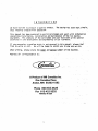
Service Manual
SERIES
1400
(R-22)
MODULAR
CUBED
ICE MAKER
12/91
161951806
1NTRQDUCTI
ON
We have s t r i v e d t o produce II q u a l i t y product.
thus i n s u r i n g t r o u b l e - f r e e opera t i o n .
The design has been k e p t simple,
This manual has been prepared t o a s s i s t servicemen and users w i t h l n f o n n a t i o n
concerning i n s t a l l a t i o n , c o n s t r u c t i o n and maintenance o f t h e i c e making
equipment. The problems o f the serviceman and user have been g i v e n special,
a t t e n t i o n i n the development and engineering o f our fceniakers.
1 ;
I f you encounter a problem which i s not covered i n t h i s manual; please fee1
f r e e t o w r i t e o r c a l l . We w i l l be happy t o a s s i s t you 40 <any way we c v ,
-
When w r i t i n g , please s t a t e t h e model and
strial number o f the machine.
Address a1 1 correspondence t o :
I
>
A Product of lMl Cornelius tnc.
One Cornelius Place
Anoka, MN 55303-1592
!
$
*
Phone 800-554-3526
Fax 6 1 2-422-3232
2
71
I
PRINTED IN USA
I
)
T A B L E
INTRODUCTION
O F
C O N T ' E N T S
............................
1
.........................
2
TABLEOFCONTENTS
...
.
SPECIFrCATfONS
.
b
b
q
3
t
.....................
4-10
REFRIGERANT CTRCUIT REMOTE CONDENSER UNITS . . . . . . . . . . . . . . . 11
INSTALLATION AND START-UP
d
...............
FOR I C E BRIDGE THICKNESS . . . . . . . . . . . . . . . . .
ELECTRICAL CIRCUIT SEQUENCE OF OPERATION
12
ADJUSTMENT
12
.....
WIRING AND SCHEMATIC DIAGRAMS . . . . . . . . . . . . . . . . . . .
S A N I T I Z I N G AND CLEANING PROCEDURE . . . . . . . . . . . : . . . . .
WATERTREATMENT . . . . . . . . . . . . . . . . . . . . . . . . . .
WINTER STORAGE . . . . . . . . . . . . . . . . . . . . . . . . . . .
CLEANING THE CONDENSER . . .
. . . ... . . . . . . . . . . . . .
SERVICE ANALYSIS . . . . . . . . . . . . . . . . . . . . . . . . . .
ADJUSTMENT AND CHECK-OUT FOR OPTICAL HARVEST
.B I N
SENSOR
6
i
13
14-17
18
19
20
20
21-23
INSTRUCTIONS FOR REMOVAL AND RE-INSTALLATION
. . . . .. . .. . . . . . . . . . . . . . .
6
OF SOLID STATE CONTROL
................... .........
ILLUSTRATED PARTS BREAKDOWN . . . . . . . . . . . . . . . . . . . .
REMOTE CONDENSER ILLUSTRATED PARTS BREAKDOWN . . . . . . . . . . . .
PARTS L I S T
2
24
25
26
27
Specifications
SERIES
8011OY
Model Number
(Corrdcnser)
1400
VIEW
Incoming Water Temp '
F
50.
70'
80'
Ambient
Temp 'F
10'
1400
1240
1180
80'
1j20
1175
1110
90'
1210
1081
1025
70'
1420
1210
1120
(Air *led)
[Water Cooled)
[Remote-Air)
.....
. .
...............
COMPRESSOR E L E C T R I C A L R A T I N G
COMPRESSOR MODEL . . . . . . . . .
CONDENSER.
REFRIGERANT CHARGE
( a i r copled).
3.25 H.P.
CRK3-0325-PFV
A i r , water o r r e m o t e
. .
64
.
...
. . .
...
. . .
(water cooled).
(remote).
.
.....
. . . . . .
OZ.
270 O Z .
R-22
k-22
R-22
TXV
REFRIGERANT CONTROL
T X V SUPERHEAT S E T T I N G
I N L E T WATER SUPPLY . . . . . . .
VOLTAGE . . . . . . . . . . . . . . .
TOTAL AMP DRAW . . . . .
. . .
CRANKCASE PRESSURE REGULA7 OR ; E i T I IiG .
,
02.
42
6O
3/8" SAE ma e f l a r e
208-230/60/
1 4 . 8 amps
45 PSI Max.
3
I N S T A L L A I I O N
A.
8.
I N S T R U C T I O N S
UNPACKING
1.
Uncrate machine and/or b i n by removing the staples from around the bottom
of cardboard c r a t e and l i f t off.
2.
Remove b o l t s fastening the c r a t e s k i d t o t h e bottom of t h e u n i t . If
a u x i l i a r y . l e g s have been purchased f o r the b i n , they should be i n s t a l l e d
a t t h i s time.
LEVELING
If legs a r e used, a d j u s t t h e l e v e l i n g legs of t h e storage b i n u n t i l the
u n i t i s l e v e l and a l l four ( 4 ) legs a r e i n s o l i d Gontact w i t h t h e f l o o r .
Leveling i s very important t o o b t a i n proper d r a l n i n g and t o m a i n t a i n the
proper l e v e l i n the w a t e r pan o f t h e i c e tuber*.
NOTE: I f the b i n i s t o be i n s t a l l e d f l u s h t o t h e f l o o r , the machine must
be sealed t o the f l o o r w i t h an approved mastic such *as .Sears #3803-0 Caulk,
Dow R.T.V.
101, 102 o r G. E. 731, 732. T h i s . 1 ~ an N.S.F. requirement and
i s the r e s p o n s i b i l i t y o f the i n s t a l l e r .
C.
D.
U N I T LOCATION
1.
Allow a t l e a s t a minimum o f s i x ( 6 ) inches a t the r e a r and side o f the
i c e machine f o r proper a i r c i r c u l a t i o n .
2.
This u n i t has been designed t o b e i n s t a l l e d i n an indoor l o c a t i o n which
i s c l e a n and which can be adequately v e n t i l a t e d ; t h e a i r and water
temperatures should never exceed 100 degrees nor f a l l below 50 degrees.
(Temperatures above 100 degrees w i l l c u t t h e i c e making c a p a c i t y below
an economical l e v e l ; temperatures below 50 degrees w i l l cause a
m a l f u n c t i o n o f t h e n o s t a t i c sensors.
3.
Tne u n i t should be located where a i r c i r c u l a t i o n i s n o t r e s t r i c t e d .
The u n i t should n o t be located near a k i t c h e n g r i l l . A i r which contains
grease vapors w i l l d e p o s i t grease on the condenser. The condenser
should always be kept clean.
U N I T SET-UP
1.
Take o f f f r o n t panel o f machine and remove hardware bag o r service
manual envelope w i t h the water s t r a i n e r enclosed.
2.
Mount the i c e maker t o the top of the i c e storage b i n or adapter i n
the proper p o s i t i o n over the i c e drop opening. The i c e maker must
then be sealed both on the o u t s i d e and the i n s i d e bottom edges w i t h
an approved N.S.F. mastic such as Dow S i l a s t i c #732, 734 o r General
E l e c t r i c RTV # l o r , 102. This i s an N.S.F. requirement and the
r e s p o n s i b i 1 it y o f the i n s t a l l e r .
3.
Remove shipping tape from evaporator c u r t a i n s .
4
I N S T A L L A T I O N
E. REMOTE CONDEWSERS
I N S T R U C T I O N S
CONT'D.
Remote condensers should be installed above the ice machine in a
leva1 configuration. They are connected to the ice making unit
by copper tubing and line valves. The male half of the line valve
is mounted qn,tbe ice making unit and the remote condenser. The
female half is soldered on the tube ends when tubing kits are
provided with the machine. If tubing kits are not provided, the
female half of the line valves will be provided in a valve kit
and the installer will mount them on the tubing he provides.
PLEASE NOTE THE FOLLOWING IN REGARD TO REMOTE CONDENSER INSTALLATION:
1. WHEN MAKING LINE VALVE CONNECTIONS, LUBRICATE RUBBER SEAL IN
MALE HALF WITH REFRIGERATION OIL. THREAD COUPLING HALVES
TOGETHER BY HAND TO INSURE PROPER MATING OF THREADS. USE
PROPER SIZE WRENCHES (ON COUPLING BODY HEX AND ON UNION NUT)
AND TIGHTEN UNTIL COUPLING BODIES "BOTTOM" OR A DEFINXTE
RESISTANCE IS FELT. USING A MARKER OR INK PEN, biARK A LINE
LENGTHWISE FROM THE COUPLING HEXT TO THE BULKHEAD. THEN
TIGHTEN AN ADDITIONAL 1/6 TO 1 / 4 TURN. THE MXSALICNMENT OF
THE LINE WILL SHOW THE DEGREE OF TIGHTENING. THIS FINAL
TURN IS NECESSARY TO INSURE THAT THE KNIFE EDGE METAL SEAL
BITES I N T O THE BRASS SEAT OF THE COWLING HALVES FORMING THE
LEAKPROOF JOINT. IF TORQUE WRENCH IS USED, TORQUE TO 35
FOOT POUNDS.
I
2.
A LOW VOLTAGE ELECTRICAL CONTROL CIRCUIT MUST BE FIELD WIRES
BETWEEN THE ICE MACHINE AND THE REMOTE CONDENSER RELAY. THOSE
WIRES SHOULD BE RUN WITH THE TUBING DURING INSTALLATION. REFER
TO APPLICABLE WIRING DIAGRAMS.
b
3.
THE REMOTE ,CONDENSER REQUIRES A SEPARATE POWER SUPPLY FROM
THE ICE MAKING UNIT. REFER TO THE REMOTE CONDENSER ON
WIRING DIAGRAM.
4.
WHEN VERTICAL LINES ARE INVOLVED IN THE INSTALLATION, FOLLOW
STANDARD REFRIGERATION PRACTICES FOR VERTICAL LINES TO &XJJRE
POSITIVE OIL RETURN TO THE COMPRESSOR. VERTICAL LIFT TO BE
NO MORE THAN 15 FEET.
5.
WE DO NOT RECOMMEND TUBING RUNS OF MORE THAN 40 FEET.
6.
A THREE WAY HEAD PRESSURE CONTROL VALVE IS USED TO MAINTAIN
A RELATIVELY CONSISTENT HEAD PRESSURE BETWEEN 180 AND 200 PSI
FOR R-22 IN THE RECEIVER IN COLD AMBIENT CONDITIONS TO INSURE
A GOOD HARVESTING OR DEFROSTING OF THE ICE SLABS ON THE
EVAPORATOR. BECAUSE OF THIS VALVE SOME LIQUID REFRIGERANT WILL
BE HELD IN THE CONDENSER.
TZIE HEAD PRESSURE CONTROL VALVE WILL,NOT OPERATE CORRECTLY
WHEN A TOTAL PRESSURE DROP OF 14 P O U N W O R MORE IS CREATED
THE ICE W I N G UNIT UTILIZING A REMOTE CONDENSER IS SHIPPED FROM
THE FACTORY WITH THE RECEIVER HOLDING THE REFRIGERANT CHARGE.
ADDITIONAL REFRIGgRANT MAY BE REQUIRED UPON INSTALLATION DEPENDING UPON THE AMBINET CONDITIONS THE REMOTE CONDENSER IS
5
OPERATING UNDER, THE CONDENSER AND LINE SIZING.
F.
MAKE ELECTRICAL POWER SUPPLY CONNECTION
Requirements:
208-230/60hz.
1 ph. o r 220V 50hz. 1 ph. when used
REFER TO SERIAL PLATE FOR MINIMUH CIRCUIT AMPACITY AND MAXIMUM T I M E
DELAY FUSE S I Z E .
ALL
WIRING MUST CONFORM TO
NATIONAL AN0 LOCAL
ELECTRICAL
CODES.
G. MAKE PLUMBING CONNECTIONS
Water supply
-
( I n s t a l l per l s c a l codes)
The water i n l e t connection t o the unit i s a 3/8" f l a r e male connections
located a t the r e a r o f t h e i c e machine.
NOTE: I f the water pressure exceeds 50 pounds, a w a t e r pressure r e g u l a t o r
should be i n s t a l l e d i n the water i n l e t l i n e between the water' shut-off valve
and the s t r a i n e r .
I n s t a l l a reducer f i t t i n g on the shut-off valve t o aecomodate the water
s t r a i n e r , which i s supplied w i t h each i c e machine and MUST be used. I n s t a l l
the water s t r a i n e r w i t h the arrow i n the proper d i r e c t i o n o f flow and w i t h
the c l e a n out plug down, This i s very important f o r cleaning. Connect
e i t h e r 3/8" o r 1/2" copper tubing between the w a t e r i n l e t f i t t i n g o f the
i c e machine and the water s t r a i n e r .
for water cooled u n i t s , two water i n l e t connections are provided; one f o r
H.
t h e i c e making (evaporator) section which i s located on the back of the
machine and i s a 3/8" f l a r e d connection. The o t h e r i s f o r the water cooled
condenser. The reason f o r the separate water i n l e t connections i s t h a t some
i n s t a l l a t i o n s use a water tower f o r c o o l i n g the water used i n the watercooled condenser and some i n s t a l l a t i o n s use t r e a t e water ( f i l t e r e d ) f o r
the i c e making i n l e t water connection. Be sure t o i n s t a l l w a t e r l i n e
(incoming) t o the 3/8" male f l a r e connection on t h e back o f the u n i t t h a t
supplies water t o the water r e g u l a t i n g valve i n s i d e .
The s e t t i n g of the w a t e r r e g u l a t i n g valve from the f a c t o r y should be 120
pounds f o r R-12 u n i t s and 225 pounds f o r R-22 u n i t s . NOTE: Always f l u s h
o u t water l i n e s before s t a r t i n g u n i t . Adjustments. i f necessary, should be
done a t i n s t a l l a t i o n .
DRAINS
Provide a s u i t a b l e trapped open d r a i n as close as possible t o the area where
the i c e maker i s going t o be i n s t a l l e d . This may be an e x i s t i n g f l o o r o r a
1-1/4" trapped open d r a i n . Two separate d r a i n l i n e s a r e required f o r a i r
cooled u n i t s , one f o r the storage b i n and one f o r the hmp Valve drain hose.
An a d d i t i o n a l separate d r a i n l i n e w i l l be required f o r w a t e r cooled u n i t s
from t h e o u t l e t o f the condenser c o i l t o the d r a i n .
l i n e s w i t h a good f a l l t o the open d r a i n .
Run a l l g r a v i t y d r a i n
ALL PLUMBING MUST BE INSTALLEO IN ACCORDANCE W I T H LOCAL CODES.
NOTE: IN SOME CASES I T H A Y BE NECESSARY TO INSULATE THE WATER SUPPLY L I N E
CONDENSATE DRIPPING TO THE FI,.OOR CAN CAUSE SERIOUS STAINING
AND DRAIN L I N E
OF CARPETS OR HARDWOOOS.
6
I N S T A L L A T I O N
I N S T R U C T I O N S
a
r
Dclnp
;i
I
I
1.
"
C O N T ' D .
Valve drain hose
Taking care not to kink or
bllapse vinyl tubing at any
point, rbute t u b s to any open,
trapped or vkted Yloor drain.
tubing to drain separately.
Do not tee any drain hoses
together. Add drain tubing
required to reach floor drain.
ADJUSRiENT OF WATER LEVEL IN RESERVOIR
With the water supply turned ON and the power supply OFF'adjust
froat to maintain water levelk" below the support web insidereservoir
(See Illustration Below)
Adjust here
F l o a t assernb
Reservoir drain cap
: ,W
-
Ice bi;ikcr w i l l not o p c r a t c p r o p e r l y when w;iCcr s u p p l y
tcmpcraturc i s b e l o w 50'F o r a b o v e 100'1;.
\J;itcr s u p p l y
p r c s s u r e must not exceed 50 PSI.
7
I N S T A L L A T I O N
J.
I N S T R U C T I O N S
C O N T ' D .
STARTING THE UNIT
A f t e r t h e i c e cuber has been unpacked and l e v e l e d and a l l plumbing and
e l e c t r i c a l connections have been made, s t a r t t h e u n i t and check f o r proper
o p e r a t i on.
A cuber has t h r e e separate c i r c u i t s :
A.
B.
C.
1.
The water c i r c u i t
The r e f r i g e r a n t c i r c u i t
The e l e c t r i c a l c i r c u i t
S t a r t checking t h e water c i r c u i t by making sure t h a t t h e r e a r e no thread
o r f l a r e j o i n t leaks, e i t h e r o u t s i d e the u n i t o r i n t h e compressor section.
Next check t h e water flow over the evaporator and make sure t h a t a l l holes
i n t h e water d i s t r i b u t o r a r e open, and t h a t there- i s no undue splash o r
l o s s o f water i n t o t h e i c e b i n .
Also check t o see i f t h e f l o a t valve i s f u n c t i o n i n g p r o p e r l y and t h e
c o r r e c t water l e v e l i s being maintained. Re-adjust i f necessary.
2. Check t h e r e f r i g e r a n t c i r c u i t by making sure t h a t the condenser f a n i s
Is the compressor running?
running. (This w i l l be e v i d e n t by a i r noise.)
(Feel t h e casing f o r v i b r a t i o n . ) Is t h e evaporator g e t t i n g c o l d ?
3-
Check b i n - h a r v e s t s w i t c h o p e r a t i o n .
8
(See proceedure i n manual)
STACKING K I T INSTALLATION INSTRUCTIONS FOR MODEL RCV-1204
1
16
2
-- 43547
857
1-
2
-
1
1
1
1
1
i n t e r f a c e cable
screw 8/32
8022
cli
plastic
20928 bushng, snap
39499 strap, t i e
-- 43534
43535
- 43541
1-
cover,
cover,
slide,
43542 s l i d e ,
43537 s l i d e ,
43539 s l i d e ,
chute t o
c h u t e bo tom
i c e t o p r i h t hand
i c e top l e t hand
i c e r i h t hand
i c e l e t hand
F
3
9
PLEASE SEE ILLUSTRATIONS FOR REFERENCE
FOR THE FOLLOWING INSTALL PROCEDURE:
1.
A f t e r t h e u n i t s are mounted on each other remove evaporator
c u r t a i n s from the bottom machine.
2.
D r i l l 2 each 3/16" holes 11 inches d i r e c t l y above weld nuts i n t h e
middle o f t h e back wall o f evaporator s e c t i o n if holes are not
already i n postion.
3.
Pre-assemble r i g h t and l e f t i c e s l i d e s as shown i n i l l u s t r a t i o n . Do
n o t t i g h t e n screws a t t h i s time, leave roan f o r adjustment.
4.
Bring i c e s l i d e s t h r u the b i n and lower machine and hang over bent
edges o f t h e top u n i t water r e s e r v o i r s .
5.
I n s e r t t h e p l a s t i c c l i s and screws t h r u i c e s l i d e flanges i n t o
weld nuts and d r i l l e d o l e s on back w a l l o f u n i t . P u l l down on i c e
s l i d e s from the bottom and t i g h t e n screws securely.
6.
I n s e r t t h e bottom chute cover p l a t e and punch a h o l e t h r u t h e
splash s h i e l d t o i n s e r t a mounting screw t h r u i t and t o t h e bottom
weld nut o f the plate. I n s e r t screws t h r u t h e t o p s l o t s o f p l a t e
i n t o the weld nuts o f the i c e s l i d e s and t i g h t e n a l l screws
secure1y.
7.
I n s e r t t o p chute cover p l a t e up alon i c e s l i d e flanges u n t i l s l o t s
match weld nuts. I n s e r t 5 screws i n o lower s l o t s p o s i t i o n and
t i g h t e n securely.
8.
Push down t h e top i c e s l i d e sections hanging on water r e s e r v o i r
bent edges and secure screws.
9.
Make sure power i s o f f t o t h e u n i t s and remove e l e c t r i c a l box
covers from both u n i t s .
10.
Remove lowest grommet from t h e l e f t side o f each e l e c t r i a l box.
11.
Remove t h e p l u g frdm chassis base pan o f the t o g u n i t i n the stack.
12.
I n s e r t the snap bushing i n t o t h e h o l e the p l u g was j u s t removed
4
from.
13.
S t r i n g i n t e r f a c e cable t h r u t h e snap bushing then i n s e r t t h e cable
t h r u each e l e c t r i c a l box h o l e and s p l i t r o m e t s .
Please Note: Make sure marked end o f cab e goes t o t h e t o p u n i t .
R
9
9
14.
R e i n s t a l l grommets i n t o e l e c t r i c a l box,
15.
Plug the i n t e r f a c e cable onto t h e open DC-3 t e r m i n a l on the l e f t
side of each s o l i d s t a t e c o n t r o l board.
Please Note: The plug connection i s
l a r i z e d and can o n l y go on
one way. be careful and make sure op"a good connection.
16.
Replace e l e c t r i c a l box covers.
17.
Plug the weld nut hole found t o t h e r i g h t o f t h e compressor with a
mastic seal ant.
18.
Remove t h e screws from both sides o f both u n i t s and i n s e r t the t i e
straps. R e i n s t a l l screws.
9
1
EX PANS IO N
VALVE
-ACCUM.
LINE
VALVES
f
UCHECK
VALVE
$
REMOTE
CONDENSER
11
RECEIVER
I
CLCCTRICAL
S
E7)UEN-C-
C I RCU 1T
N
An L.E.D. digit display mounted on the solid state control board will show
a status number 0 , 1 , 2 , 4 , 6 6 and a decimal point to indicate what is
happening in the operation of the unit.
The electrical sequence of operation you will see on the digit display for
a normal ice making cycle will be as follows:
The status number 0 will be shown telling you the unit is making ice. The
solid state control DELAYS the start of the water pump until the evaporator
temperatures reaches-.
Approximately six minutes after the start up
in the freeze cycle a decimal point will appear to the lower right of the "0"
to tell you that the evaporator sensor has been switched on. After the
evaporator temperature has pulled down low enough for the correct amount of
ice to be on the evaporator, the decimal point will begin to flash and stay
flashing for approximately 20 seconds. If evaporator stays below the set
point, the harvest cycle will start. A number " 1 " on the digit display will
indicate that the machine is in its harvest cycle with the hot gas valve
open. The water pump continues to operate and the water dump solenoid valve
is now open. The water pump shuts off approximately 15 'seconds later after
the water reservoir is pumped out.
PLEASE NOTE: During the freeze cycle in low ambient condition the condenser
fan motor will be cycled on and off through the condenser sensor and solid
state control board. The fan cycling pressures in relation to the temperatures
sensed will be approximately 180# for cut out and 230# for cut in of the
fan motor.
ADJUSTMENT FOR ICE BRIDGE THICKNESS
An ice bridge connecting all cubes is necessary for a proper harvest or
discharge of cubes from the evaporator.
To increase ice "bridqe" thickness careful ly turn adjustment screw counter
clockwise no more than one turn at a time., Wait and check thickness before
re-adjust ing
.
-ADJUST
HERE
f-k
fNCREASE
ClRCUl T
BOARD
12
A D J U S T M E K T
A N D
C l i E C K - 0 1 1 1 '
F,,OR H A R V E S T - B I N
S W I T C H E S
"
CHECKOUT PRQCEUbRE
L
I
Move , t h e e v a p o r a t o r e u r t a i n ( s ) a w a y f r o m
a c h i n e shol;l'qd' hen * s h u t ~ f fi na p p r o x i m j t l y
T u r n on t h e i c e machine
t h e e v a p o r a t o r ( s ) . The i
8 seconds.(See d e t a i l A88)
Slowly l e t t h e e v a p o r a t o r c u r t a i n ( s ) move b a c k t o w a r d t h e e v a p o r a t o r ( s )
u n t i l t h e bot,,tom ed9ei"Df t h e c u r t a i n ( s ) i s a t l e a s t a t t h e b e n t e d g e
of the water reservoir o r closer t o the evbporator,'With the curtain(s)
a t t h a t p o s i t i o n , the machineshould s t a r t . ( S e e d e t a i l C )
i
*
ADaUSTMENT PROCEWRE
nutsand move p r o x i m i t y s w i t c h
curta
i siPn
roperly
I f adjustment i
c l o s e r t o t h e curtaifi(s)a
(See d e t a i l A
1
$
J
'
*
f
> "
b
R e - c h e c k p e r a b o v e proce.edu
13
RD
I
1
I
I 1
' I
Condensor I
LWH
Water
Dump
Switch
RCV 2
Con tro I
Rev. F
BL
PWH-
G
swI
Harvest 8
Bin Switch
Reset
Switch
~
s
~
o
HDds
DC5
I
c
,
OR
I
Switch
(
Bin Switch
BR
RD
I
Y L
2081230 VOLTS
AC & WC-140O-MH
60 H Z
Note .-
The solid state control DELAYS the start of
the water pump until the evapurator
temperature reaches 20. F.
Whita ond black connector blocks are
/MPo*;rANT %EYED"ond MUST be inserted correctly
on circuit board. DO NOT USE FORCE.
14
PART NO. 4 0 6 0 6
A R T W O R K 505.41
REV. J
I
Water
Dump
Solenoid
CS-I50 Remote Condensor
Manual Reset
High
Pre s u r e Control
RCV-2
Con?rol
Rev. F
Water
Pump
GY
U==S
Suction
BRc
I
I
To 8tocked UnitDC3 if roquired I
Bin
Harvest
Switch
8 N
Dc3
a
Water
,+
SUI
Optional
Remote
-+I L+1 Alorm Box
i+Dcl
3::h
1
1
GY
d3TDc5
Harvest a
Bin Switch
-BR
BDCZ
RC-1400-MH
-
The solid state control DELAYS the start of
the water pump until the evaporator
temperature reoches 20° F.
White and block connector block8 are
IMPORTANT aKEYED" ond BUST be inrerted correctly
on circdt board. DO NOT USE FORCE.
#Ot88
P A R T NO. 161909002
ARTWORK
50740
REV. B
15
1
- RD
Power Relay
8
Outlet Box
wL
I
@Pressor
,
-RD
I
RD
I
Manual Reset
High
Pressure 3Cocltrol
Condensor
Fan Motor
'
RD
1
Condensor
-ORWater
Pump
,
WH
BL
Suction
a B R 6
G
Water
RCV 2
Control
Rev. F
To stacked UnitD C 3 if required
Harvest &
Bin Switch s
Switch
I
4, Optional
-hi
Remote
I '
-
I
I lt
Alarm Box
Swl
I
c;y
I
I'I
.!.-
Reset
e.
:
.
EL-
I
208/230 VOLTS
AC Ek W C - 1 4 0 0 - ~ H - 3
60 HZ
The solid stgte control DELAYS the start of
the water pump' uhtil the evapmator
tl?mperature reaches 20° F.
White and b l a c k connecfor blocks are
'MPoR7AN7" aKEYED"and MUST be inserted correctly
on circuit board. DO NOT USE FORCE.
Note :
*
^
16
PART N O . 41182
ARTWORK 50561
REV. J
3PH
SANITIZING
AND
CLEANING
PROCEDURE
1.
Remove front panel to gain access to the on-off-clean switch.
2.
Push switch to "clean" and allow the ice on the evaporator to
release or melt away.
3.
Remove all ice from storage bin.
4.
If lime scale is present add 2 oz. of "Lime-A-Wayn or Yalgon
Nickel-Safe Ice Machine Cleaner" directly into water reservoir.
Circulate for no longer than 15 minutes. Go to Step 7 to flush
out the system before going to Step 5.
CAUTION: All ice machine cleaner must be flushed
out of the system before the s a n i t m g solution
is used in Step 5. The reaction of the two
chemicals can cause hazardous gases to be
generated.
5.
Pour 1/2 02. of household bleach into the water reservoir and
circulate for 15 minutes to sanitize the circulating water system
including the evaporator, pump, distributor and a1 1 interconnecting
vinyl tubing. Go to Step 7 to flush out.
6.
Mix a sanitizing solution of 1 oz. household bleach to one gallon
of water. Using a non-metallic bristle brush, scrub the following:
a.
b.
c.
Inside surfaces of the ice bin including top
and door.
Inside surfaces of the icemaker to include
evaporator section in the ice machine including
the top, front panel anmd evaporator splash curtain.
Make sure splash curtain is correctly positioned.
7.
Depress dump valve switch on top of control box and allow cleaner
or sanitizer to drain away. Allow float valve to fill reservoir
with clean fresh water, circulate for apporximately 1 minute.
Depress dump valve switch and allow water to drain away.
Repeat 3 times.
8.
Push switch from Iklean'l to "on1' position.
9.
Replace front panel.
18
W A T E R
T R E A T M E N T
Automatic ice-making machines can q u i t working f o r any number o f reasons,
mechanical, e l e c t r i c a l o r f a u l t y refrigeration, but water problems foul them
UP faster than almost anything elsq. While i c e machines vary I n design, you
can apply these water treatment t i p s t o a l l of them.
1.
START WITH THE WATER
The mineral content of water .varips i n d i f f e w n t areas and as the
chart shows, high hardness and a l k a l i n i t y counts combine t o form
insoluble calcium carbonate or lime scale. I f t h i s condition i s
constant, the intake water must be treated constantly t o prevent
scale formation i n the i c e machine.
2.
<
PREVENT LIME SCALE FORMATION
We mcomnend the i n s t a l l a t i o n o f a Calgon Microment Feeder on the
incoming water line. No. X-88 Feeder i s recomnended f o r i c e machines
w i t h a capacity of 400-450 lbs. per day. F i l l the feeder w i t h 6R
Hicromet, the slowly soluble poly-phosphate which l a s t s s i x months
before renewing the 8-02. charge.
Constant treatment with 6R Micromet w i l l control l i m e scale and
prevent minerals from s t i c k i n g t o the freezing surfaces i n i c e
machines. Result smooth movement o f i c e slabs, good harvest of
i c e cubes, e f f i c i e n t , automatic production.
-
3.
REMOVE OBJECTIONABLE TASTE OR ODOR
Ifthe bad taste o r odor i s traceable t o the w a t e r source, i n s t a l l a
Calgon Fine Carbon F i l t e r t o the incoming water l i n e . The No. 1-1/28
Fine Carbon F i l t e r i s ideal f o r machines making up t o 500 pounds of
i c e per day and w i l l remove bad taste, odors, and problems caused
by chlorine i n the water supply. I n some instances, slime growths may
cause odor problems and these growths can be removed by the use Of
1f quid I c e machine cleaner.
4.
SERVICE REGULARLY
A service program t o clean the ice machine a t regular i n t e r v a l s and
check on f i l t e r and feeder charges i s important. I n the long run, i t
w i l l assure adequate water treatment, reduce emergency c a l l s and a i d
i n the trouble-free performance o f automatic ice making machines.
19
W I N T E R
S T O R A G E
I f the u n i t i s t o be stored i n an area where the temperature w i l l drop
below freezing, i t i s most important t h a t a l l water l i n e s be drained t o
prevent them from freezing and possible rupture.
To blow out the water l i n e , disconnect the water supply a t the cabinet
i n l e t and use a i r pressure t o force the water i n t o the water reservoir
pan. This can then be h o v e d ‘from the water pan.
CLEANING
T H E
C O N D E N S E R
I n order t o produce a t f u l l capacity, the r e f r i g e r a t i o n condenser must be
kept clean. The frequency of cleaning w i l l be determined by surrounding
condition. A good maintenance plan c a l l s for an inspection a t l e a s t
every two months.
Remove the lower f m n t panel af the machine. With a vacuum cleaner, remove
a l l accumulated dust and l i n t t h a t has adhered t o the finned condenser.
CAUTION:
CONDENSER COOLING FINS ARE SHARP.
USE CARE WHEN CLEANING.
1.
I f the condenser i s being cleaned from the back of the machine, remove
a l l accumulated dust, d i r t etc., ’that has adhered t o the finned
surface with a vacuum cleaner.
2.
I f the u n i t i s being cleaned from the front, remove lower panel, turn
the power switch o f f and blow through the finned surface o f the
condenser past the fan blade t o remove accumulated dust, etc.
20
STATUS INDICXTOR
STATUS
MPLANATION
0
Unit is in freeze cycle, d i n g
ice, rn problems.
1
vnit is in harvest cycle, ice
should drop shortly, ry) problems
2
~ndicatesa full bin andition, '
unit off, water cxrrtain being held
POSSIBLE CAUSE
.
open with ice.
If "2" is s h a m h t bin isn't f u l l ,
check for individual cube holding
curtain open. Harvest Bin switch not
adjusted properly.
Unit OFF due to suction line not
p l l i ~ d o w nto at least 40'F.
Manual reset required.
Low on refrigerant. Defective Ixv.
Ccmpressor defective or inefficient.
Defective p e r relay, w n ' t close
Defective start relay, won't start
ampressor.
voltage to ampressor
no start. Defective C.P.R. valve.
Defective sensor (brown wire).
SENSOR NOT INSULATED PROPERLY.
6
Unit is OFF due to mndenser
tenperat= climbing to6 high.
Manual reset required.
Dirty condenser. Defective fan motor or
blade. * Gross overCharge4 Extremly
high ambient tanperatwe, above 120'F.
Defective sensor (orange wire).**
Decimal
Point
Indicates that all m o r s ,
except mndenser, are switched
off for first six minutes of
freeze cycle.
tbrmal time delay, approxinptely
6 minutes.
4
OFF
Decimal
.
i
Indicates that evaporator and
suction line sensors have
switched "cW~.
mint
ON
Decimal
Point
has pulled down and unit will go
FLASHING
into harvest after time delay.
Indicates evaporator tgcperature
MANUAL =GI'
- PUSH MV%TR
*
Normal time delay of approximately
20 secnnds before harvest cycle
begins.
-
TO "OEF" WAIT 10 SM33NDs
PUSH RESET BcrrroN
swJ[TcH
Nqt applicable to Wat&w3oled
** N o t
units.
appliable to Remote units.
21
- PUSH
"ON"
T R O U B L E
S H O O T I N G
C O N T R O L
THE
S O L I D
S T A T E _
B O A R D
To detennine i f the c i r c u i t board and senmors a r e functioning c o r r e c t l y
under a l l operating parameters. the adverse conditions must be simulated
t o check out the d i g i t a l d i s p l a y s t a t u s nubers.
P R O C E DU
To check 16
To check 14
To check #2
-
-
a€
Block condenser fan blade on s t a r t up. Condenser should
g e t hot within two minutes and shut u n i t off on 16,
condenser too hot.
Remove suction l i n e sensor from thermowell anytime during
f r e e z e cycle. Machine should shut o f f on 14, suction l i n e
t o o warm when the evaporator temperature gets low enough
t o s t a r t the harvest cycle.
Hold water c u r t a i n open anytime a f t e r u n i t goes i n t o
harvest. Machine should shut down w i t h i n approximately
8 seconds on 1 2 , f u l l bin.
XMPORTANT: Dual evaporator units use two harvest-bin switches, m e
For each evaporator. These switches are normally c l o s e d .
When the unit goes into a harvest c y c l e , both switches must temporarily
be open before the machine will go back into the freeze c y c l e .
When the bin is full eicher switch being open for longer than 8
s e c o n d s will s h u t off the machine.
Both harvest-bin swtiches must be closed to bring the unit back on.
TO
check 11
-
io
-
To check
Push defrost button anytime during freeze Cycle and u n i t
should go i n t o harvest. I 1 indicates a harvest cycle,
no problems.
A "0" indicates that the u n t t i s i n the freeze Cycle and
there are no problems.
PLEASE NOTE: I n rape cases a "0" can be displayed on khe
control board and the canpressor n o t running i n water cooled
and m o t e a i r cooled machcnes. I f t h i s occurs, the manual
reset highspressure control w i l l be open and must be r e s e t
f o r proper operation. The control i s located i n the upper
rear, r i g h t corner of the compressor compartment.
A f t e r reset, check o u t the machine f o r the possible causes
o f the problem.
22
T t R O U B L E ' S H O O T I N,G
1.
Turn o f f power 00 machine,
'
T H E
SENSO,,RS
.
2. Remove the f r o n t panel and e l e c t r i c a l box cover o f the machine.
3.
Cut the suspected sensor w i r e a t l e a s t s i x inches from the thermowell
i n which i t i s located.
4.
Remove the sensor from the thennnvlelli.
5.
C a r e f u l l y separate the wires and s t r i p the , i n s u l a t i o n o f f the end.
6,
Pack a glass o r c o n t a i n F r , M
ice-water solwtiQn,+,Check t
accurate thennometar.
water t o make an
e i c e water w i t h an
I n s e r t the senior i n t o
r a min4mum of two
,
1
I
7.
m i nut e s
8.
.
With a r e r o d ohmmeter measure t h e resistance across the two wires o f
the sensor lead. It should read 2815 ohms + o r -10% (281 ohms).
NOTE:
If- t h e above ohm reading i s h o t w i t h i n the range stated, the
sensor i s bad and should be replaced.
I
i
R E C , O N , N E C T I Q N ,,O'F,
SENS0.R
A F T E R
A., G O O D
0.R
R E P L A C E M E N T
TROUBLESHOOTING
4
1
Carefully separate the wires o f the sensor leads csming 'from the s o l i d
s t a t e c o n t r o l and s t r i p t h e i n s u l a t i o n o f f the end of each wire.
2.
Reconnect t h e sensor leads and t w i s t the s t r i p p e d ends t i g h t l y .
w i t h the proper sized w i r e nuts.
3.
Tape a l l t h e w i r e nut connections t o i n s u l a t e connections from each o t h e r .
23
Secure
REMOVAL
CAUTION:
1.
,O:F~
S O L I D
S T AT E
,
C O,N T R~O,L F R O M
M A C H I N E
THE CIRCUIT BOARD IS FRAGILE, HANDLE WITH CARE.
Turn o f f power t o machine.
9
2.
Remove f r o n t panel.
3.
Remove e l e c t r i c a l box l e f t \ front cover.
4. 'Disconnect the through w i r e p l u g connections from c i r c u i t board.
5.
C a r e f u l l y lift any cdrher o f 'the circuit board w h i l e pinching closed
the top p a r t o f t h e ' p l a s t i c '%ta
o f f " s d p p o ~ tw i t h needle nose
p l i e r s . The c i r c u i t boaird has t o be praduaTl'y woPked up over a l l
'five of the "stand o f f " supports. The c i r c u i t board w i l l n o t "pop o f f "
u n t i l a14 supports have been .Pinched closed and t h e bbard i s then
holding them i n t h a t p o s i t i o n .
R E I N S T A L L A T I O N
O F
S O L I D
S T A T E
CONTROL
1.
A l i g n a l l holes i n the c i r c u i t board over the p l a s t i c stand-off
supports.
2.
C a r e f u l l y push downward a t a l l hole locations u n t i l board seats on
a l l the stand-off support's: (Sometimes a snap w i l l be heard as t h i s
seating takes place.)
3.
A f t e r the c i r c u i t board i s seated, c a r e f u l l y connect the three plugs
t o the c i r c u i t board. Note: Plug connects are p o l a r i z e d , make sure
ttOe p l u g i s I n s e r t e d c o r r e c t l y .
24
iI
I
PARIS
<J>.
NO.
-72
3
4
5
6
7
8
9
10
11
12
13
14
15
16
17
18
19
20
21
22
23
24
25
26
27
28
29
30
31
32
33
34
35
36
37
38
39
40
41
42
43
44
45
46
47
48
49
50
51
52
53
54
55
56
57
58
L I S 1
PART NO
SERIES
DESCRIPTION
Control , circuit board
Switch, on-off-clean
Relay, compressor start
Relay, power
Capacitor, compressor start
Capacitor, compressor run
Drier
Valve, crankcase pressure regulating
Valve, Schrader
Core, Schrader v
Cap, Schrader va
Compressor
Motor, condenser fan
Blade, condenser fan
Scroud; condenser
Condenser
Sensor, condenser temp.
Pump, water
Valve, thermostatic expansion
Sensor, suction line temp.
Valve, hot gas
Tube, water pan to pump inlet
Cap, reservoir drain
Reservoir, water (right)
Float and valve
Bracket, float and valve
Hose
Tee
Hose
Switch, reset
Evaporator (right)
End cap
Distributor, water (right)
Curtain, evaporator (right)
Curtain, evaporator (left)
Bracket, front curtain mount (right)
Condenser coi 1, water cooled
Valve, water regulating
Bracket, back curtain mount (right)
Switch, harvest-bin prox. (right)
Valve, water dump
Valve, check
Switch, low pressure (remote only)
Control, high pressure sensor (remote only)
Valve, line (male 1/2")
Valve, line (male 5/8")
Splash guard
Accumulator
Recei ver
Transformer 24 volt
Heater, crankcase
Control, high pressure manual reset (WC & remote)
Distributor, water (left)
Evaporator (left)
Bracket, front curtain mdunt (left)
Bracket, back curtain mount (left)
Reservoir, water (left)
S w i t c h , harvest-bin prox. (left)
b
Solenoid valve, l i q u i d l i n e pump down
Sensor, evaporator
Switch, water dump valve
1400
16 I466b3G-
37356
4 1042
407 13
4 1044
41043
37439
37440
20654
21214
23988
41 145
39899
39898
40586
39897
38703
39144
161921003
38703
40712
38790
45681
41449
165681000
16569&t8b
987
434 12
42680
45905
22279
43056
166050001
166050002
43530
271 77
121 1
38743
43446
4278 1
41275
16 1773000
39644
42 145
42624
4 1463
166073000
38057
23683
40602
39358
43057
45904
43529
4065 1
164829001
43447
23082
161456002
45866
25
lLLUSTRATED
P A R I S
BREAKDOWN
REMOlE CONDENSER
ILLUSTRATED PARPS BREAKDOWN
e
Illus.
No.
1
2
3
4
5
6
7
8
9
10
11
12
Part No.
Description
35832
39898
161871001
27181
42 145
42624
28627
27384
42 146
16 1870001
42625
3735 1
Clip, retainer
Blade, condenser fan
Motor, condenser fan
Re1 ay
Line valve (make connection 1/2")
Line valve (male connection 5/8")
Bracket, fan motor mounting
Bracket, mounting
Line valve (female 1/2")
Condenser
Line valve (female 5/8")
Control valve, head pressure
27