1
SEPARATE CIRCULATOR
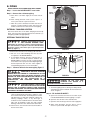
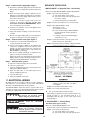
Step 5 - Connect boiler supply pipe. Figure 1.
a. Shut off the cold water supply valve to the boiler, and
drain it using a hose attached to the drain valve at the
boiler.
I. BOILER MATE™ as Separate Zone - Non-Priority
A. Use of separate BOILER MATE™ ZONE CIRCULATOR
b. When the boiler system piping is drained, cut the
piping to accommodate the supply line tee. Install the
tee between the boiler supply outlet and any system
zone valve or flow check.
Step 1 - Disconnect electrical power.
a. Turn off the boiler service switch.
b. Turn off the safety switch (if separate from
the service switch).
c. Switch off the branch circuit breaker.
c. Connect the circulator flange and mount the
circulator to the boiler supply. Be sure the flow
arrow points towards the BOILER MATE™. Mount
the second flange to the circulator.
Step 2 - Remove electrical box cover on Thermostat.
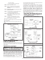
Step 3 - Wire BOILER MATE™ using
Schematic #1 or #2.
a. Install BX connector.
b. Insert outside wiring to BOILER MATE™
through electrical conduit opening on
thermostat.
c. Complete exterior electrical wiring per
Schematic #1 or #2.
d. Connect a 3/4" NPTM to a 3/4" sweat adapter to the
second circulator flange.
e. Using short lengths of tubing, connect the 3/4"shutoff valve.
f. Run the 3/4"copper tubing with necessary fittings to
the point of connection to the boiler supply tee.
Step 6 - Connect boiler return pipe. Figure 1.
Step 4 - Turn boiler low-limit control (it is part of the
boiler control) to the off position.
a. Connect the 3/4" NPT, boiler return fitting and
connect the drain valve and union.
b. Sweat a short length of tubing to the adapter and
connect the weighted check valve with the flow
towards the boiler (preventing flow towards the
BOILER MATE™). Failure to do so will result in the
BOILER MATE™ overheating.
c. Run the 3/4" tubing and fittings as required to the
point of connection to the boiler return.
NOTE: This point must be between the boiler return
tapping and any system circulator(s). Failure to do so
will result in the BOILER MATE™ overheating.
Note: Some boilers require minimum setting of low limit.
SEPARATE CIRCULATOR
Step 7 - Refill the boiler system
a. Open the cold water supply valve to the boiler.
b. Check for system leaks.
c. Close the weighted check valve on the boiler return
piping of the BOILER MATE™
d. Open the drain valve on the boiler return line to
release entrapped system air.
e. Close the drain valve
f. Open the weighted check valve.
C. ELECTRICAL WIRING
All wiring must be in accordance with local codes, regulations,
and ordinances or, in the absence of such codes, the National
Electrical Code ANSI/NFPA No. 70, latest edition.
Step 5 - Adjust boiler high-limit control to the desired
setting. In most cases 180° F to 200° F
is acceptable.
Step 6 - Re-assemble electrical box cover.
The BOILER MATE™ thermostat can be used for either 24 or
120V AC. The thermostat is packaged separately and is installed
by sliding the capillary tube into the thermostat well.
Step 7 - Re-connect electrical power.
B.
First
hazard.
Electrocution
dis-connect all electrical power
before doing any electrical work.
Electrocution hazard. The BOILER
must
be
electrically
MATE™
grounded.
Use of only the heating system circulator.
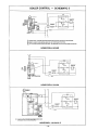
When wiring a separate zone valve, follow all steps in 1A
except for Step 3c. Use Schematic #3(A, B or C)
depending upon the type of zone valve. (Zone valve
sizing per pg. 5)
II. BOILER MATE™ - Priority Wiring
Hot Water Before Space Heating
A. Use of separate BOILER MATE™ zone.
A DPDT relay is to be used. Refer to Schematic #4.
Electrical supply must come from the
boiler side of boiler’s emergency
shut-off switch in order to prevent
unsafe boiler operation.
Step 1 - Disconnect electrical power.
a. Turn off the boiler service switch.
b. Turn off the safety switch (if separate from
-8-