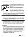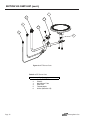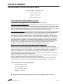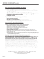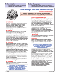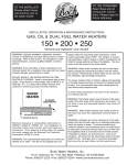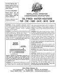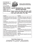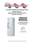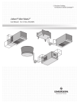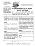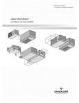
1
To the Installer:
To the Consumer:
Please attach these instructions
next to the water heater.
Please read these and all component
instructions and keep for future reference.
Atmospheric Gas Instruction Manual
EZ 75-76, EZ 100-76
Warranty, Registration Card and Parts List are included.
Homeowner: Please remember to return the Registration Card!
䊱
! WARNING
Improper installation, adjustment, alteration,
service or maintenance can cause serious
injury or property damage. Refer to this
manual. For assistance or additional
information, consult a qualified installer or
service agency.
䊱
! WARNING
If the information in these instructions is not
followed exactly, a fire or explosion may result
causing property damage, personal injury or
death.
䊱
! WARNING
Do not install on combustible flooring. Install
in accordance with all local codes. In the
absence of local codes, refer to ANSI
223.1/NFPA 54 and/or CSA B149.1.
䊱
! CAUTION
The recommended temperature for normal
residential use is 120°F. The dial on the aquastat
does not always reflect the out-coming water
temperature and it could occasionally exceed
120°F. Variation in out-coming temperature
could be based on factors including but not
limited to usage patterns and type of installation. Test water at the tap nearest to the water
heater. See page 9 for measuring the outcoming water temperature.
䊱
! WARNING
Hotter water increases the risk of scald injury.
Before adjusting the water temperature setting,
read this instruction manual. Temperatures at
which injury occurs vary with the person’s age
and the length of exposure. The slower
reaction time of children, elderly or physically
or mentally challenged persons increases the
scalding hazard to them. It is recommended
that lower water temperatures be used where
these exposure hazards exist. Households with
small children or invalids may require a
temperature setting less than 120°F to prevent
accidental contact with hot water. To produce
less than 120°F, use point-of-use
temperature limiting devices.
#23405
If higher water temperature is needed in part
of the water system, automatic temperature
limiting devices must be used on all lines to
water taps.
䊱
! WARNING
Flammable vapors may be drawn to this water
heater from other areas of the structure by air
currents. Do not store or use any flammable
liquids in the vicinity of this heater.
䊱
! WARNING
Water heater blankets may restrict air flow to
the water heater and cause fire, asphyxiation,
personal injury or death.
THIS MANUAL HAS BEEN PREPARED TO
ACQUAINT YOU WITH THE INSTALLATION,
OPERATION, AND MAINTENANCE OF YOUR
WATER HEATER AND TO PROVIDE IMPORTANT
SAFETY INFORMATION.
Read all instructions thoroughly before
attempting installation or operation of your
water heater. Keep these instructions for future
reference.
Local plumbing and electrical codes must be
followed in the installation of this water
heater. In the absence of a local code use the
UNIFORM PLUMBING CODE and the NFPA
Code. Local codes may supersede instructions
in this installation manual.
These instructions are a guide for the correct
installation of the water heater. The manufacturer will not be liable for damages caused by
failure to comply with the installation and
operating instructions outlined on the
following pages.
Installation, testing, and replacement of gas
piping, appliances, or accessories, and repair
and servicing of equipment, shall be
performed only by a qualified agency.
FAILURE TO FOLLOW THESE INSTRUCTIONS
OR ALL APPLICABLE BUILDING CODES
AND REGULATIONS VOIDS THE WARRANTY
ON THIS WATER HEATER.
Rev1 8/09
IMPORTANT SAFETY INSTRUCTIONS
䊱
!
WARNING
If the information in these instructions is not followed exactly, a fire or
explosion may result causing property damage, personal injury or death.
FOR YOUR SAFETY!
- Do not store or use gasoline or other flammable vapors and liquids in the
vicinity of this or any other appliance.
- WHAT TO DO IF YOU SMELL GAS
• Do not try to light any appliance.
• Do not touch any electrical switch; do not use any phone in your
building.
• Immediately call your gas supplier from a neighbor’s phone.
Follow the gas supplier’s instructions.
• If you cannot reach your gas supplier, call the fire department.
- Installation and service must be performed by a qualified installer,
service agency or the gas supplier.
䊱
!
DANGER
Water heaters utilizing Liquefied Petroleum gas (LP) are different from
natural gas models. A natural gas heater will not function safely on LP gas
and vice versa. To avoid possible equipment damage, personal injury or
fire: DO NOT connect this water heater to a fuel type not in accordance
with the rating label. These units are only certified for a single fuel type.
䊱
!
DANGER
Failure to install the draft hood and properly vent the water heater to the
outdoors as outlined in this manual can result in unsafe operation of the
water heater. To avoid the risk of fire, explosion, or asphyxiation from
carbon monoxide, never operate this water heater unless it is properly
vented and has adequate air supply for combustion. Be sure to inspect
the vent system for proper installation at initial start-up; and at least
annually thereafter. See the Maintenance section for more information.
SAVE THESE INSTRUCTIONS
Page 2
Atmospheric Gas
TABLE OF CONTENTS
Section I: Specifications . . . . . . . . . . . . . . . . . . . . . . . . . . . . . . . . . . . . . . . . . . . . . 4
Section II: General Information. . . . . . . . . . . . . . . . . . . . . . . . . . . . . . . . . . . . . . . . 5
Section III: Pre-Installation . . . . . . . . . . . . . . . . . . . . . . . . . . . . . . . . . . . . . . . . . . . 7
Section IV: Installation . . . . . . . . . . . . . . . . . . . . . . . . . . . . . . . . . . . . . . . . . . . . . 10
Section V: Operation . . . . . . . . . . . . . . . . . . . . . . . . . . . . . . . . . . . . . . . . . . . . . . . 13
Section VI: Maintenance . . . . . . . . . . . . . . . . . . . . . . . . . . . . . . . . . . . . . . . . . . . . 15
Section VII: Troubleshooting . . . . . . . . . . . . . . . . . . . . . . . . . . . . . . . . . . . . . . . . . 16
Section VIII: Parts List. . . . . . . . . . . . . . . . . . . . . . . . . . . . . . . . . . . . . . . . . . . . . . . 17
Section IX: Warranty . . . . . . . . . . . . . . . . . . . . . . . . . . . . . . . . . . . . . . . . . . . . . . . 19
Atmospheric Gas
Page 3
SECTION I: SPECIFICATIONS
F
Cold
Hot
ON
PILOT
Anode Rod (2)
OFF
G
Draft Hood
T&P Relief
Valve
C
A
B
Gas/Temp.
Control
D
E
OFF
WARNING
READ ALL INSTRUCTIONS BEFORE LIGHTING
WARM
CAUTION
HOTTER WATER
INCREASES THE
RISK OF
SCALDING
INJURY
VERY
HOT
Drain
Figure 1: All Models
a.
Sh
Di
a.
(LB ippi
S) ng
We
igh
t
sC
on
n.
on
n.
Di
ia.
.D
tC
tle
76,000
73
133 69.19 65.38 26.00 58.25 14.50 11.00 4.00
1.00
1.00
0.50
391
100 76,000
73
153 69.81 66.00 28.00 57.94 14.50 11.00 4.00
1.00
1.00
0.50
485
Ga
Ou
75
EZ 100-76N
F
EZ 75-76N
E
In
G
D
C
let
Co
nn
DIMENSIONS (inches)
o
Sto
o
rag
e(
Ra
G
(BT ted I AL)
U/ npu
Re HR) t
Ris cove
r
e
1st (GP y @ 1
00
10 Hr. H)
F
0 F De
Ris liv
e ( ery
A
GA @
L)
B
Table 1: Dimensions
Model
For LP models change suffix "N" to "LP"
Working Pressure: 150 PSI (1034 kPa)
Test Pressure: 300 PSI (2068kPa)
For natural gas: Manifold pressure = 4" W.C. (1.00 kPa); Inlet pressure range 5-14" W.C. (1.25 - 3.49 kPa)
For propane gas: Manifold pressure = 10" W.C. (1.00 kPa); Inlet pressure range 11-14" W.C. (2.74 - 3.49kPa)
T&P valve installed
All Bock products meet or exceed current ASHRAE standards.
These products are design certified by UL (Underwriters Laboratories) and meet ANSI Z21.10.3 requirements for operation up to 180°F (82°C).
Approved for use as an automatic circulating tank water heater or automatic storage water heater.
WARNING: Do not install on combustible flooring. Installation shall be in accordance with all national and/or local codes.
In the absense of local codes, refer to NFPA 54 and/or CSA B149.1.
CAUTION: The recommended maximum hot water temperature setting for normal residential use is 120°F (49°C). Bock recommends a
tempering valve or anti-scald valve be installed and used according to the manufacturer's directions to prevent scalding.
Page 4
Atmospheric Gas
SECTION II: GENERAL INFORMATION
WHEN YOU RECEIVE YOUR NEW WATER HEATER
Check the new equipment to see if all components are in good condition. If damage is
observed or parts appear to be missing, contact your wholesaler.
WATER TREATMENT/FILTRATION
In areas where poor water conditions are suspected (i.e. lime, iron, and other minerals), it is
essential that the water be tested and appropriate action taken to prevent damage to the
water heater and ensure the quality of the water.
TEMPERATURE CONTROL
The water heater is equipped with a gas thermostat to monitor tank temperature and control
operation of the main burner. For domestic hot water, the proper temperature setting is 120°F.
For commercial applications, the maximum approved temperature setting is 180°F.
A built in, non-cycling Energy Cut-Off (ECO) is standard on all gas thermostats. In the event
that the water temperature becomes excessive (200°F), the ECO will shut off all gas to the
water heater. If an ECO has detected an over-temperature condition and has opened, the
control will not function and a replacement will be required.
The thermostat is factory set at 120°F. See Figure 6 for thermostat letter and temperature
relationships. If hotter water is required a tempering device or anti-scald device must be
installed at the domestic hot water outlet of the heater or at the point of use. Table 3 details
the approximate relationship of water temperature and time with regard to scald injury. It is
important for the user to understand the necessity of tempering or anti-scald devices when
using hotter water in domestic water heating systems.
䊱
! CAUTION: Hot water in excess of 120°F can cause scalding!
Bock recommends a tempering valve or anti-scald valve be installed and used according to
the manufacturer’s directions to prevent scalding. Many state and local codes now require
installation of these devices. The tempering valve or anti-scald valve will ensure potable
water temperatures at the desired set point with a higher degree of accuracy.
Table 2: Scald Temperature/Time Relationships
APPROXIMATE
TEMPERATURE/TIME
RELATIONSHIPS TO
SCALDING
120°F
More than 5 minutes
125°F
1 1⁄2 to 2 minutes
130°F
About 30 seconds
135°F
About 10 seconds
140°F
Less than 5 seconds
145°F
Less than 3 seconds
150°F
About 1 1⁄2 seconds
155°F
About 1 second
Atmospheric Gas
Page 5
SECTION II: GENERAL INFORMATION (cont.)
ANODE RODS
The anode rod is used as a sacrificial element within the volume of the storage tank. The
purpose of the magnesium anode rod is to protect the inside of the tank against corrosion.
Anode rods should be inspected twice in the first year and at least yearly once a time interval
for inspection has been developed. Water conditions can influence the consumption rate of
the anode rods. Please see the Maintenance section of this manual for instructions on how to
change the anode rods.
䊱
! CAUTION
Hydrogen gas is produced in a hot water system served by the heater that has not
been used for a long period of time (2 weeks or more). Hydrogen gas is extremely
flammable. To reduce the risk of injury under these conditions, it is recommended that
the hot water faucet be opened for several minutes at the kitchen sink before using any
electrical appliance connected to the hot water system. When hydrogen is present,
there will probably be an unusual sound such as air escaping through the pipe as the
water begins to flow. There should be no smoking or open flame near the faucet at the
time it is open.
TEMPERATURE AND PRESSURE RELIEF VALVE (T&P)
䊱
! CAUTION
To reduce the risk of excessive pressures and temperatures in this water heater, install
temperature and pressure protective equipment required by local codes and no less
than a combination temperature and pressure relief valve certified by a nationally
recognized testing laboratory that maintains periodic inspection of production of listed
equipment or materials, as meeting the requirements for Relief Valves and Automatic
Gas Shutoff Devices for Hot Water Supply Systems, ANSI Z21.22. This valve must be
marked with a maximum set pressure not to exceed the marked maximum working
pressure of the water heater. Install the valve in an opening provided and marked for
this purpose in the water heater, and orient it or provide tubing so that any discharge
from the valve exits only within 6 inches above, or at any distance below, the
structural floor, and does not contact any live electrical part. The discharge opening
must not be blocked or reduced in size under any circumstances.
䊱
! CAUTION
Scalding injury and/or water damage can occur from either the manual lifting of the
lever or the normal operation of the T&P valve. If it is not piped to a proper drain. If the
valve fails to flow water or reseat, call your plumber.
The T&P valve is factory installed. A discharge drain tube must be installed (responsibility
of the installer) and shall terminate plain, not threaded, 6 inches above the floor drain.
The drain tube material must be approved for temperatures of 120 F or greater and a
pressure of 150 PSI or greater.
o
Page 6
Atmospheric Gas
SECTION II: GENERAL INFORMATION (cont.)
BACKFLOW PREVENTER (CLOSED SYSTEM)
Some local municipal codes and ordinances require the use of these devices on potable
(domestic) water lines. Where backflow preventers are required, it will be necessary to install
a thermal expansion tank (designed for use with potable water) in order to prevent pressure
build up in the water heater and associated piping, which could cause the T&P
valve to discharge. Follow the expansion tank manufacturer’s recommendations when
selecting a tank for your hot water system.
Note: Working pressure of the water heater is 150 PSI. Do not exceed 150 PSI.
SECTION III: PRE-INSTALLATION
LOCATION
䊱
! CAUTION
This water heater must be located in an area where leakage of the tank, water line
connections, or the temperature and pressure relief valve will not result in damage to
the area adjacent to the water heater or to lower floors of the structure. When such
location cannot be avoided, a suitable drain pan must be installed under the water
heater. The drain pan depth must be suitable for draining and collecting water. The
drain pan can be purchased from your plumbing professional. The drain pan must be
piped to an adequate drain and all drain piping must be at least 0.75” in diameter
and pitched for proper drainage.
䊱
! CAUTION
DO NOT store or use gasoline or other flammable, combustible, or corrosive vapors
and/or liquids in the vicinity of the water heater or any other appliance.
IF YOU SMELL GAS:
• DO NOT try to light any appliance.
• DO NOT touch any electric switch; do not use any telephone in your building.
• Immediately call your gas supplier from a telephone in another building. Follow your
gas supplier’s instructions.
• If you cannot reach your gas supplier, call the fire department.
DO NOT OPERATE THE APPLIANCE UNTIL THE LEAKAGE IS CORRECTED!
䊱
! CAUTION
Do not drop water heater or lay heater down on its side. Move the water heater into
position by sliding or using an appropriately sized hand truck.
Atmospheric Gas
Page 7
SECTION III: PRE-INSTALLATION (cont.)
NOTE: Locate the heater so it is not subject to physical damage from moving vehicles or
flooding. Do not locate the water heater in a room where swimming pool chemicals or large
quantities of water softener salt are kept. Installing a water heater
in this environment will result in premature failure of tank and
burner components due to corrosion caused by these elements
diffusing into the air.
DO NOT INSTALL THE WATER HEATER ON COMBUSTIBLE
FLOORING. Place on noncombustible flooring and maintain
clearances prescribed by this manufacturer and per code NFPA 54. If
the water heater must be located on combustible flooring it must be
raised off the floor with a layer of 4'' concrete block laid so the air
holes are aligned as shown in Figure 2. Consult with local code
officials before using this method. Please consult local codes, NFPA
Figure 2
54 and/or contact Bock Water Heaters with questions concerning
proper flooring materials. Leave adequate room for periodic maintenance of heater and burner.
The water heater should be placed as near to the chimney as practical in order to keep vent
connector length to a minimum. Consult National Fuel Gas Code for proper vent configuration.
Minimum clearance to combustible construction is: SIDES 6"; BACK 6"; FRONT 24";
DRAFT HOOD; 18". The installation of this water heater must conform with local
codes and ordinances. In the absence of local codes, the installation must comply
with the National Fire Protection Association (NFPA 54) Code.
COMBUSTION AND VENTILATION AIR
The water heater must be installed in a location with an adequate air supply for combustion,
ventilation and draft control. Unsafe levels of carbon monoxide (CO), condensation and
sooting may result if the room does not have an adequate air supply. See “National Fuel Gas
Code (NFPA 54)” or the discussions of “Unconfined Space” and “Confined Space” below. Poor
ventilation will also result in hot spots around the heater. Temperatures over 90°F near the
water heater generally indicate a lack of ventilation.
UNCONFINED SPACE
Unconfined space is defined by NFPA 54 as a space with a volume greater than 50 cubic feet
(during typical use) per 1000 BTUH of the total combined input of all fuel burning appliances
in the space. Rooms leading directly to the installation space through doors that cannot be
closed can be considered part of the space. Exception: Buildings with full vapor barriers, tight
doors and windows or air infiltration rates of less than 0.35 air changes per hour will be
considered a confined space and require additional air supplies.
CONFINED SPACE
Confined space is defined by NFPA 54 as a space with a volume less than 50 cubic feet (during
typical use) per 1000 BTUH of the total combined input of all fuel burning appliances in the
space. Buildings or rooms of unusually tight construction are also considered a confined space.
See “Unconfined Space: Exception”.
When installing fuel burning appliances in a confined space, air must be supplied to that
space from either inside or outside of the building as conditions allow.
A. Inside Air Supply: A confined space shall be provided with two permanent openings; one
within 12 inches of the top and one within 12 inches of the bottom of the enclosure. These
openings shall lead directly to room(s) of sufficient volume so that the combined volume of
all the space meets the criteria for unconfined space. Each opening shall have a minimum free
area of 1 square inch per 1000 Btu/hr of the combined total input of all fuel burning
appliances in the space. Each opening shall have an area of not less than 100 square inches or
a minimum dimension of not less than 3 inches.
Page 8
Atmospheric Gas
SECTION III: PRE-INSTALLATION (cont.)
CONFINED SPACE (CONT.)
B. Outside Air Supply: Confined spaces shall be provided with two permanent openings; one
within 12 inches of the top and one within 12 inches of the bottom of the enclosure. These
openings shall communicate directly, or by ducts, with the outdoors or spaces that
communicate with the outdoors.
1.) Leading directly to the outside or through vertical ducts: Each opening shall have a
minimum free area of one square inch per 4000 Btu/hr of total input rating of all equipment
in the enclosure.
2.) Leading to outside through horizontal ducts: Each opening shall have a minimum free
area of one square inch per 2000 Btu/hr of total input rating of all equipment in the enclosure.
Note: All ducts shall have the same cross sectional area as the free area of each opening to
which they connect. The minimum dimensions of all ducts shall not be less than three inches.
Powered combustion air supplies are also commercially available and may be used.
LOUVERS & GRILLES
In calculating the free area of an opening, consideration must be given to the blocking effects
of louvers or grilles protecting the opening. Any screens used must be no finer than 1⁄4 inch
mesh. If the free area of a louver or grille is known, this should be used in calculating the size
of opening required. If free area is unknown, it may be assumed that wood louvers will have
20 to 25% free area and metal louvers and grilles will have 60 to 75% free area. Louvers and
grilles should be fixed in the open position or interlocked with the equipment so that they
open automatically during equipment operation.
VENTING
The water heater shall be located as close to the chimney as practical. Long lateral runs will
result in intermittent combustion problems and unsafe operating conditions. Total vent
height should be a minimum of 6 feet. Shorter vent heights could result in unstable draft and
nuisance lock outs.
The venting system should be sized according to National Fuel Gas Code: NFPA 54/ANSI
Z223.1 (most recent edition) using the “Natural” column. If you do not have a copy of this
code one can be obtained at www.NFPA.org for a nominal fee. Copies of the NFPA venting
tables are also reprinted in the Bock Engineering Manual available from your Bock Representative or by download from www.bockwaterheaters.com. Note: Do not reduce vent size more
than one size smaller than the vent connector supplied with the heater. If vent size must be
reduced one size, use full size vent connectors on the vent hood and reduce vent size as far
from the water heater as practical. B vent, L vent or multi-fuel venting may be used. Vent
tables supplied by the vent manufacturer may also be used in sizing the vent system.
Venting system must be capable of producing –0.02" WC (inches of water column) draft
minimum. If draft of –0.02" WC cannot be produced with an existing vent system, a draft
inducer may be required. Installations common vented with large vent hood equipped
appliances such as heating boilers may require vent dampers on the heating boiler connectors
for proper vent operation during no-heating season.
Check the building for items that can cause severe negative pressure problems such as large
exhaust fans. If these devices are installed in the same building check for their effect on draft
and combustion. All fuel burning appliances must be isolated from the effects of these devices
to operate properly. Failure to address this issue will result in unsafe operation and shorten
appliance life spans.
Your Bock water heater may also be operated with a power venter. The power venter must be
properly sized and adjusted to provide proper draft. Power venter wiring must turn on the
power venter on a call for heat and must prove venter operation before allowing the burner to
start. Refer to the power venter instructions for proper wiring and adjustment procedures.
Atmospheric Gas
Page 9
SECTION IV: INSTALLATION
WATER CONNECTIONS
䊱
! CAUTION
This water heater incorporates fittings that contain a nonmetallic lining. DO NOT apply
heat to these fittings when making sweat connections to the heater. Sweat tubing to
an adapter before securing adapter to any fittings on water heaters.
ALL PIPING SHOULD CONFORM TO LOCAL CODES AND ORDINANCES. It is highly
recommended that unions and shut-off valves are installed at the potable water connections
to allow for isolation and/or movement during service. All piping should be adequately
insulated with an approved material to minimize heat loss.
POTABLE WATER CONNECTIONS
THE WATER HEATER MUST BE FILLED WITH WATER BEFORE LIGHTING THE
BURNER.
1) Close the main water supply valve before continuing with the installation. After the main
water supply is shut-off, relieve the water line pressure by opening a faucet. Once the pressure
has been relieved, close the faucet. The “Cold” and “Hot” potable water connections are
labeled on the water heater. Install a union and shut-off valve at both potable water
connections. All piping should be 3/4” diameter new copper or larger. A tempering valve or
anti-scald valve should be installed at the potable water outlet and used according to the
manufacturer’s specifications to prevent scalding.
2) If a backflow preventer is required in the cold water supply, a properly sized expansion tank
must be installed to control thermal expansion. Do not operate the water heater in a closed
system without installing a thermal expansion tank. Follow the expansion tank manufacturer’s recommendations when selecting a tank for your system.
3) Following installation of the water lines, open the main water supply valve and fill the
water heater. Open several hot water faucets to relieve air from the system. After water is
flowing through the faucets and the system is void of air, close the faucets and check for water
leaks in the system.
Note: Do not try to heat hard water as this will drastically reduce heater life. Install a water
softener or other scale reducing water treatment system if the water heater is being installed in
a hard water area (water hardness higher than seven grains).
Page 10
Atmospheric Gas
SECTION IV: INSTALLATION (cont.)
GAS CONNECTIONS
䊱
! CAUTION
Do not use this water heater with any gas other than the type listed on the rating label.
Check the rating label on the front of the water heater and make sure the gas to be used
matches the gas stated on the rating label. Consult your local gas company or Bock Water
Heaters with any questions.
A manual valve, union, and a sediment trap should all be provided in front of the gas
thermostat. All gas piping must conform to local codes and/or the National Fuel Gas Code,
ANSI 223.1/NFPA 54 (latest edition).
Supply piping should be sized according to the charts found in the National Fuel Gas Code
for natural gas applications.
Note: When sizing the gas piping to the heater, make sure that the pressure at the valve is
sufficient when all other appliances are operating. Undersized gas piping will reduce water
heater performance and life as well as result in nuisance lockouts. Also verify that the gas
service and meter are sized properly for the load.
Gas piping should be carried oversize, i.e.: 3⁄4 inch or 1 inch or larger for 1⁄2 inch valve to
within 2 feet of the valve itself. This sustains pressure at the valve during start-up to prevent
flashbacks caused by momentary pressure loss. For natural gas, 5" W.C. pressure must be
maintained upstream of the gas valve during operation. For LP gas, a minimum of 11" W.C.
must be maintained upstream of the gas valve. A 1⁄8 inch NPT pipe connection should be
installed upstream of the manual shut-off valve to check incoming gas pressure.
During pressure testing of the gas supply piping, close the manual gas shut-off valve to the
water heater. Test pressure shall not exceed 1⁄2 PSIG (14" W.C). The gas valve is only rated for
1
⁄2 PSIG. To test at pressure greater than 1⁄2 PSIG, close the manual shut-off valve and
disconnect the gas operating valve.
Turn on gas and inspect piping for leaks by “painting” each joint with soap and checking for
bubbles. Do not use open flame. The pipe thread compound that is used on gas piping must be
of the type resistant to propane gas. Do not use teflon tape on gas piping. Note: For high
altitude applications (above 2000 feet) contact Bock Water Heaters.
DRAFT HOOD AND VENTING
This water heater must be installed with the factory supplied draft hood. See Figure 3 for
placement. Vent connectors must be attached to the draft hood to connect the water heater to
the gas vent or chimney. The vent connector must be the same diameter as the outlet of the
draft hood. Never use a smaller diameter vent connector. Horizontal vent connectors must be
pitched upward to the chimney at least 1/4” per foot of length. Vent connector joints should
be securely fastened with sheet metal screws. For further specifications, see the National Fuel
Gas Code (NFPA 54).
䊱
! DANGER
Substitution, elimination or relocation of the draft hood will result in unsafe operation
and void the warranty of your water heater. Improper venting or misuse of the draft
hood can result in unsafe operation causing bodily injury, explosion, fire or death. To
avoid the risk of fire, explosion, or asphyxiation from carbon monoxide, NEVER operate
this water heater unless it is properly vented and has an adequate air supply.
Atmospheric Gas
Page 11
SECTION IV: INSTALLATION (cont.)
DRAFT HOOD INSTALLATION
1. Locate the two predrilled holes in the top pan.
2. Align and insert the draft hood legs (without screw holes)
into the holes in the top pan.
3. Using a drill and the two sheet metal screws (supplied),
fasten the other two legs (with screw holes) to the top pan.
The draft hood should now be securely joined to the water
heater.
Figure 3: Install Draft Hood
Draft Hood
Vent to Chimney
(Pitch up 1/4" per Foot)
Shut-Off Valve
Union
Shut-Off Valve
Union
Heat Trap (6" min)
Heat Trap
(6" min)
Cold Water
Supply
Hot Water Outlet
to Mixing Valve
(not shown)
Backflow
Preventer (optional)
T&P Relief
Valve
Anode (1 of 2)
Expansion Tank
Gas Supply
Gas Shut-Off Valve
Relief Valve
Discharge Line
to Floor Drain
Union
Drain
Valve
Sediment
Trap
Gas
Thermostat
Figure 4: Recommended Water, Gas, Vent Connections
Page 12
Atmospheric Gas
SECTION V: OPERATION
FOR YOUR SAFETY READ BEFORE LIGHTING
WARNING: If you do not follow these instructions exactly, a fire or
explosion may result causing property damage, personal injury or loss
of life.
A.
This appliance has a pilot which must be
lighted by hand. When lighting the pilot,
follow these instructions exactly.
B.
BEFORE LIGHTING smell all around the
appliance area for gas. Be sure to smell next
to the floor because some gas is heavier than
air and will settle on the floor.
WHAT TO DO IF YOU SMELL GAS
Do not try to light any appliance.
Do not touch any electric switch; do not use
any phone in your building.
Immediately call your gas supplier from
a neighbor's phone. Follow the gas supplier's
instructions.
If you cannot reach your gas supplier, call
the fire department.
C.
Use only your hand to push in or turn the
gas control knob. Never use tools. If the
knob will not push in or turn by hand, don't
try to repair it, call a qualified service
technician. Force or attempted repair
may result in a fire or explosion.
D.
Do not use this appliance if any part has been
under water. Immediately call a qualified
service technician to inspect the appliance
and to replace any part of the control system
and any gas control which has been under water.
LIGHTING INSTRUCTIONS
1. STOP! Read the safety information above
on this label.
2. Set the thermostat to lowest setting.
3. Turn gas control knob clockwise
to "OFF."
PILOT GAS
BUTTON
GAS CONTROL
KNOB
Natural Gas
GAS CONTROL
KNOB
LP
4. Wait five (5) minutes to clear out any gas.
If you then smell gas, STOP! Follow "B"
in the safety information above on this label.
If you don't smell gas, go to the next step.
5. Remove both access panels and insulation
located below the gas control.
6. Find pilot - follow metal tube from
gas control. The pilot is mounted
on a bracket at an upward angle.
7. Turn gas control knob
counterclockwise
PILOT
BURNER
THERMOCOUPLE
to "PILOT."
8. Push in gas control knob or pilot gas button all
the way and hold in. Immediately light
the pilot with a match or multi-purpose lighter.
Continue to hold the control knob in for about
one (1) minute after the pilot is lit. Release
knob or button and it will pop back up. Pilot
should remain lit. If it goes out, repeat steps 3
through 8.
If the knob does not pop up when released,
stop and immediately call your service
technician or gas supplier.
If the pilot will not stay lit after several tries,
turn the gas control knob to "OFF" and call
your service technician or gas supplier.
9. Return both access panels and the insulation
to their respective locations.
10. Turn gas control knob counterclockwise
to "ON."
11. Set thermostat to desired setting.
TO TURN OFF GAS TO APPLIANCE
1. Set the thermostat to lowest setting.
2. Turn gas control knob clockwise
to "OFF."
REPLACING THE GAS CONTROL
1. The thermostat is designed with a single-use gas shutoff device. In the event that the gas shutoff
circuit is open, the control must be replaced. STOP! DO NOT ATTEMPT TO OPERATE THE
APPLIANCE. CALL A QUALIFIED SERVICE TECHNICIAN TO REPLACE THE GAS CONTROL.
2. Turn the gas control knob clockwise
to "OFF."
3. Turn off all gas to the appliance and remove the gas line from the gas control.
4. Drain all water from the tank of the appliance. See instruction manual for further information.
5. Loosen and remove the thermocouple, main burner tube, and pilot burner tube connection from the
bottom of the gas control.
6. Remove the gas control from the tank (turn counterclockwise
to loosen).
7. Install the new gas control into the tank (turn clockwise
to tighten) and reconnect the
thermocouple, main burner tube, pilot burner tube and gas line to the gas control.
8. Refill the appliance with water. See instruction manual for further information.
9. With the gas control set to "OFF," turn on gas to the appliance. Check for leaks in the gas line and at
the main burner tube and pilot burner tube connection to the gas control. If a leak is detected, STOP!
Follow the safety instructions above on this label.
10. To put the appliance back into operation, follow the safety information and lighting instructions above
on this label.
23079
Figure 5: Instructions To Put The Water Heater In Operation
Atmospheric Gas
Page 13
SECTION V: OPERATION (cont.)
INSPECT THE INSTALLATION AND ADJUST THE CONTROLS
During the initial warm-up of the stored water, check for proper combustion by sampling
combustion gas at a point just below the exit of the flue. O2 readings should be in the range of
4.5-5.0% with CO levels at 0 ppm. Both combustion chamber access panels and insulation
(placed between panels) shall be installed when performing the combustion test. O2 readings
that greatly deviate from the specified range may lead to unsafe operating conditions. Factors
that can lead to O2 levels outside of the specified range include inadequate or excess draft
caused by ambient conditions or venting, obstructions underneath the water heater
preventing sufficient flow of air to burner, and improper inlet or manifold gas pressures. For
natural gas, the manifold pressure is preset at 4.0” w.c. and the acceptable inlet pressure is in
the range of 5-14” w.c. For propane gas, the manifold pressure is preset at 10.0” w.c. and the
acceptable inlet pressure is in the range of 11-14” w.c. See the “Pre-Installation” section of this
manual for information on clearances, air supply, and venting.
The thermostat has been adjusted to 120°F at the factory. Wait until thermostat has shut off
gas to the main burner. Wait 30 seconds following shut-off of gas, then set thermostat to the
highest temperature. The main burner should relight. Set thermostat to the lowest
temperature; the main burner should go out. The thermostat should be adjusted to the
minimum setting that will meet the hot water needs of the homeowner or commercial
application.
䊱
! CAUTION
There is a scald potential if the thermostat is set too high. The recommended temperature
setting for normal residential use is 120°F. If higher temperature settings are needed for
combined appliance applications or commercial use, an automatic tempering valve
must be installed on all domestic hot water lines.
MEASURING THE OUTCOMING WATER TEMPERATURE
The thermostat is factory set at 120°F for
domestic use. It is the responsibility of the
building owner to verify that the installer follows
the recommended quantitative testing for
measuring the outlet water temperature. To make
sure that the system works properly after installation and in the future, it is recommended that
the heater’s performance be measured and
monitored. Run water out of the tap nearest the
heater until it comes out warm. Using a
calibrated thermometer, take a measurement. If
the water is not at a suitable temperature for the
installation, have a qualified service person
adjust the temperature control. Contact Bock for
further information if needed.
This log (or a similar one) should be filled out as
follows:
Date
Page 14
Time
Person running test
Figure 6: Approximate Temperature and
Dial Setting Relationship
Set temp °F
Outlet temp °F
Atmospheric Gas
SECTION VI: MAINTENANCE
NOTICE TO THE OWNER: If you are having a mechanical problem with your water heater,
contact your service company or installer.
WATER PIPING
On an annual basis, all piping should be checked for leakage at joints, shut-off valves, and
unions.
T&P RELIEF VALVE
On an annual basis, the temperature and pressure relief valve should be checked for proper
operation. First, attach a drain line to the valve to direct the water discharge to an open drain.
This is very important because the temperature of the discharge could be very hot. Second,
lift the lever at the end of the valve several times. The valve should operate freely and return
to its original position properly. If water does not flow out of the valve, remove and inspect
for corrosion or obstructions. Replace with a new valve if necessary. Do not repair the faulty
valve as this may cause improper operation.
ANODE RODS
Anode rods should be inspected twice in the first year and at least yearly once a time interval
for inspection has been developed. It is recommended to check the rod(s) six months after the
heater is installed. If the anode rod had reduced in size by two-thirds of its original diameter
of 3/4” or shows signs of pitting, it is time for replacement. Take the following steps when
changing the anode rod(s):
1. Shut off water supply.
2. Open any faucet to relieve tank pressure.
3. Remove caps on water heater top; push insulation aside.
4. Use a 1 1/16” six-sided socket wrench and a breaker bar. Snap hard to break the anode
rod seal.
5. Remove rod(s) and replace with new rod(s).
6. Turn water supply back on and leave faucet open until air is out of line.
7. Turn faucet off and check that new rod(s) doesn’t leak.
8. Snap caps back into place.
FLUSH THE TANK
Elements in the water such as lime and iron may accumulate in the heater. Accumulation of
these elements can keep your water heater from operating at peak efficiency and may lead to
premature tank failure. It is recommended that the tank is drained and flushed thoroughly
once a year to prevent buildup.
Atmospheric Gas
Page 15
SECTION VI: MAINTENANCE (cont.)
INSPECT THE VENTING SYSTEM
The vent system should be checked at least once a year for damage and blockage. A draft and
combustion test is also recommended.
If necessary, the water heater flue may be cleaned with a brush or flexible wire. Before
proceeding:
1) Turn the gas valve OFF.
2) Wait at least 5 minutes for the combustion chamber and flue to cool.
3) Use a brush or flexible wire to clean the flue. This can be done through the top of the flue.
It is not necessary to remove the burner.
4) Slide the brush down the flue at the base of each row of fins. This should knock any rust
flakes into the combustion chamber for removal.
䊱
! WARNING
If the flue is blocked with soot this indicates serious combustion problems related to the
building and/or installation. These must be addressed before placing the water heater back
in operation.
5) Vacuum any sediment collected in the combustion chamber before restarting the heater.
Access to the combustion area can be obtained through the removal of the two access panels
and insulation. Be sure to replace all parts to their original positions prior to operating the
water heater.
SECTION VII: TROUBLESHOOTING
䊱
! CAUTION
For your safety, the repair and servicing of this equipment shall only be performed by a
qualified agency.
Table 3: Troubleshooting
Problem
Cannot light pilot
Pilot will not stay lit when gas
control knob or pilot gas button is
released.
Poor combustion (sooting, CO)
Rumbling noise during burner
operation
Insufficient hot water
Water too hot or not hot enough
Possible causes
1) Gas control knob not positioned correctly
2) Air in gas line
3) Clogged pilot orifice
4) Pinched pilot tube
5) Pilot tube leaking
1) Thermocouple connection is loose
2) Bad thermocouple
3) Safety magnet breakdown
4) Single use gas shut-off device opened in thermostat
1) Accumulation of scale on burner
2) Combustion air openings or flue/venting restricted
3) Inadequate combustion/ventilation air to room
Recommended Action
1) Refer to lighting instructions
2) Purge gas line
3) Clean or replace
4) Repair or replace
5) Tighten connection at thermostat
1) Tighten connection at thermostat
2) Replace thermocouple
3) Replace thermostat *
4) Replace thermostat *
1) Turn OFF burner and clean
2) Inspect and clean.
3) See "Pre-Installation" section
1) Scale or sediment build-up in tank
1) Clean/flush tank
1) Heater undersized for load
2) Low gas pressure
1) Thermostat set too high or low
2) Thermostat out of calibration
3) Excessive water temperature and pilot failure.
1) Reduce hot water usage rate
2) Check gas supply and manifold pressure
1) Adjust setting as required
2) Replace thermostat *
3) Replace thermostat *
* In the event that the gas thermostat needs to be replaced, contact a qualified agency to perform the replacement.
Page 16
Atmospheric Gas
SECTION VIII: PARTS LIST
2
3
1
4
2
5
10
6
7
8
9
Figure 7: ezFIT Parts
Table 4: ezFIT Parts
1
2
3
4
5
Atmospheric Gas
Part Description
Hot Outlet Nipple
6
Anode Rods
7
Draft Hood
8
Dip Tube
9
T&P Relief Valve
10
Gas Thermostat
Inner Access Door
Insulation
Outer Access Door
Drain Valve
Page 17
SECTION VIII: PARTS LIST (cont.)
1
3
2
4
2
5
6
Figure 8: ezFIT Burner Parts
Table 5: ezFIT Burner Parts
1
2
3
4
5
6
Page 18
Part Description
Burner
Pilot Kit
Main Burner Tube
Pilot Tube
Thermocouple
Orifice (Natural or LP)
Atmospheric Gas
SECTION IX: WARRANTY
LIMITED WARRANTY FOR GAS-FIRED WATER HEATER
Bock Water Heaters, Inc.
110 S. Dickinson Street
Madison, WI 53703
Phone: 608-257-2225
WHAT DOES THIS LIMITED WARRANTY COVER?
This limited warranty applies only to the original consumer purchaser.
General Defects and Malfunctions: This warranty covers defections and malfunctions in your
new water heater for a period of one year from the original installation date. We will repair or
replace, at our option, any defective or malfunctioning component of the water heater. This
limited warranty will terminate if you sell or otherwise transfer the water heater, or the water
heater is installed at a location different from its original installation location.
Tank and Heat Exchanger: We also warrant that the tank and heat exchanger will not leak due
to defective materials or workmanship for five years from the date of original installation or
from date of manufacture in the event the Limited Warranty Registration Card was not
completed and returned to manufacturer. If the tank and heat exchanger is leaking and we
have verified that the leak is due to a defect in materials and workmanship, we will replace
the tank with a tank that is the nearest Bock model available at the time of replacement. If a
replacement tank is provided, it will remain warranted under this section as if it were the
original tank. For example, if we send you a replacement tank under this limited warranty
two years after the original installation date, then the replacement tank will remain
warranted for the remaining three years after the original installation date.
HOW DO YOU GET SERVICE UNDER THE LIMITED WARRANTY?
In order for the warranty period to begin on the date of installation, you must return the
warranty registration card attached below within 30 days of purchasing the water heater. You
may also register your water heater online at www.bockwaterheaters.com. You must have a
copy of the original sales receipt at the time you request service. Failure to return the
warranty registration card and provide a copy of the sales receipt will result in the warranty
period beginning from the date of manufacture.
To get service under this limited warranty you should contact either the dealer or installer. If
dealer or installer is unknown you can contact us via e-mail at
[email protected] or call us Monday through Friday between the hours of
8 o’clock a.m. to 5 o’clock p.m. Central Time at the following number: 1-608-257-2225.
You can also write us at the following address:
Bock Water Heaters, Inc.
Warranty Support Group
110 S. Dickinson Street
Madison, WI 53703
We will respond not later than ten days after we have received your request for service.
Atmospheric Gas
Page 19
SECTION IX: WARRANTY (cont.)
WHAT DOES THIS LIMITED WARRANTY NOT COVER?
This limited warranty does not cover water heaters that are or were:
• Incorrectly installed, especially where the installation violates state or local plumbing,
housing or building codes.
• Operated at inappropriate settings, excessive pressures or temperatures.
• Exposed to adverse local conditions and specifically sediment or lime precipitation in the
tank or corrosive elements in the atmosphere or unacceptable water quality.
• Installed outside the United States or Canada.
• Accidentally damaged.
Also, we will not cover the following charges, costs and losses:
• Any freight or delivery charges.
• Any removal or installation charges.
• Charges to return the water heater or part to the manufacturer.
• Water damage, loss or damage to property, inconvenience or loss of use.
WHAT WILL VOID THE LIMITED WARRANTY?
If you do any of the following, you will void this limited warranty:
• Fail to return the warranty registration card within 30 days.
• Fail to retain an original copy of your sales receipt.
• Fail to retain the actual rating plate from the water heater.
• Alter or remove the serial number.
• Transfer or sell the water heater.
• Remove the water heater from its original location and install it somewhere else.
• Fail to follow the care and maintenance instructions provided with the water heater.
• Remove the anode rods.
• Fail to inspect and replace the anode rods (you must retain and present your paid receipts
as proof of anode rod replacement).
HOW DOES STATE LAW RELATE TO THIS LIMITED WARRANTY?
This is a limited warranty. WE MAKE NO OTHER EXPRESS WARRANTIES WITH RESPECT TO
THIS WATER HEATER. We will not assume, nor authorize any person to assume for us any
other liability in connection with the sale or operation of this water heater. ANY IMPLIED
WARRANTIES, INCLUDING MECHANTABILITY OR FITNESS FOR A PARTICULAR
APPLICATION, IMPOSED ON THIS SALE UNDER THE LAWS OF THE STATE OF SALE ARE
LIMITED TO ONE YEAR. This warranty gives you specific legal rights, and you may also have
other rights which vary from state to state. Some states do not allow limitations on how long
an implied warranty lasts, so the above limitation may not apply to you.
WE WILL NOT BE RESPONSIBLE FOR WATER DAMAGE, LOSS OF USE OF THE UNIT,
INCONVENIENCE, LOSS OR DAMAGE TO PERSONAL PROPERTY, WHETHER DIRECT OR
INDIRECT, AND WHETHER ARISING IN CONTACT OR TORT. Some states do not allow the
exclusion of incidental or consequential damages, so the above exclusion may not apply to
you.
Bock Water Heaters, Inc. • 110 South Dickinson Street • Madison, WI 53703
Telephone 608 -257-2225 • Fax 608 -257-5304
www.bockwaterheaters.com
Page 20