1
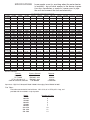
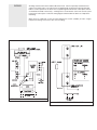
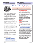
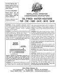
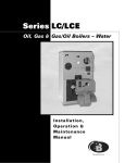
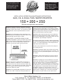
TO THE CONSUMER:
Read these and all
component instructions. Please keep for
future reference.
TO THE INSTALLER:
Please attach these
instructions next to
the water heater.
INSTALLATION, OPERATION & MAINTENANCE INSTRUCTIONS
GAS, OIL & DUAL FUEL WATER HEATERS
150 • 200 • 250
Warranty and registration card included
WARNING: Improper installation, adjustment, alteration,
service or maintenance can cause serious injury or property damage. Refer to this manual. For assistance or additional information, consult a qualified installer or service
agency.
always reflect the outcoming water temperature, which
could occasionally exceed 120°F. The variation in outcoming temperature could be based on factors including but not
limited to usage patterns and type of installation. Test your
water at the tap nearest to the water heater.
WARNING: If the information in these instructions is not
followed exactly, fire or explosion may result and can cause
property damage, personal injury or death.
WARNING: Hotter water increases the risk of scald injury.
Before changing the temperature setting, read the instruction manual. Temperatures at which injury occurs vary with
the individual’s age and length of exposure.
DO NOT INSTALL THE WATER HEATER ON COMBUSTIBLE FLOORING. Install in accordance with all local
codes. In the absence of local codes, refer to NFPA 31 or
ANSI Z21.10.1, or contact Bock Water Heaters with
questions concerning proper flooring materials.
The slower reaction times of children, elderly and physically
or mentally impaired persons increases the scalding hazard
to them. It is recommended lower water temperatures be
used where these situations exist.
To lower water temperature use point-of-use temperature limiting devices.
WARNING: Flammable vapors may be drawn to this water
heater from other areas of the structure by air currents. Do
not store or use any flammable liquids in the vicinity of
this heater.
WARNING: Water heater blankets may restrict air flow to
the heater and cause fire, asphyxiation, personal injury or
death.
Minimum clearance to combustible construction is:
SIDES 6”; BACK 6”; FRONT 24”. The installation of
this water heater must conform with local codes and
ordinances. In the absence of local codes, the installation must comply with the National Fire Protection
Association (NFPA 31) Code.
WARNING: The recommended temperature for normal residential use is 120°F. The dial on the aquastat does not
WARNING: Hydrogen gas can be produced in a hot water
system that had not been used for an extended period-generally, two weeks or longer. To prevent possible injury
under this situation, we recommend that a hot water faucet
be wide open for several minutes before you use ANY electrical appliance that is connected to the hot water system.
If hydrogen is present, an unusual sound – such as air
escaping – will come from the open faucet as the hot water
begins to flow. Hydrogen gas is extremely flammable –
there must be no open flame near this open faucet.
Bock Water Heaters, Inc.
110 S. Dickinson St. • P.O. Box 8632 • Madison, WI 53708-8632
Phone: 608/257-2225 • Fax: 608/257-5304 • www.bockwaterheaters.com
SPECIFICATIONS
Leave ample room for servicing when the water heater
is installed – do not block access to the burner, inspection door, handholes or controls. Leave room to pipe
the unit and connect the fuel and electricity.
BURNER SPECIFICATIONS
Bock MultiFlue Series
150-400
150-600
150-800
200-450
200-650
200-850
200-1150
250-800
250-1000
250-1250
250-1500
Nominal Storage
176 gal.
8 in.
3
4
168 gal.
8 in.
5
4
160 gal.
10 in.
7
6
221 gal.
8 in.
3
4
212 gal.
8 in.
5
4
204 gal.
10 in.
7
6
192 gal.
12 in.
10
10
273 gal.
10 in.
7
6
260 gal.
12 in.
10
8
251 gal.
14 in.
12
10
242 gal.
14 in.
14
11
150E-600
150E-800
200E-450
200E-650
200E-850 200E-1150 250E-800 250E-1000 250E-1250 250E-1500
4.5 gph
600000
Wayne
EH
4.5 x 80B
371-028
6.0 gph
800000
Wayne
EH
5.5 x 80A
193-020
3.2 gph
450000
Wayne
EH
3.0 x 80B
371-028
4.6 gph
650000
Wayne
EH
4.5 x 80B
371-028
6.1 gph
8.2 gph
6.0 gph
7.1 gph
9.0gph
11.0 gph
850000
1150000
800000
1000000 “1,250,000” 1500000
Wayne
Wayne
Wayne
Wayne
Wayne
PowerFlame
EH
FH
EH
FH
FH
C2-OAS
6.0 x 70B 2-4.0 x 80B 6.0 x 70B 2-3.5 x 80B 2-4.5 x 80B 6.00x70B*
193-020
193-022
193-020
193-022
193-022
Carlin
Carlin
201 CRD 301 CRD
2.5 x 70B* 4.0 x 80B*
Carlin
301 CRD
Carlin
Carlin
201 CRD 301 CRD
2.5 x 70B* 4.0 x 80B*
Stack Size, in.
Turboflues, Qt.
Anode Rods, Qt.
Bock Oil 150E-400
Fired Model
Max. Fire Rate
3.0 gph
Btu/hr input 400000
Burner Make
Wayne
Model
EH
Nozzle
3.0 x 80A
OEM Number 371-026B
Burner Make
Model
Nozzle
OEM Number 9828500B361E
Bock Dual 150DF-400
Fuel Model
Max. Fire Rate
3.0 gph
Btu/hr input 400000
9859400B
5.0 x 80A or 70W*
9859400B
Btu/hr input
400000
J15A-10
5.0 x 80A or 70W*
9859400B
9859400B
200DF-450
200DF-650
200DF-850
200DF-1150
250DF-800
4.5 gph
600000
6.0 gph
800000
3.2 gph
450000
4.6 gph
650000
6.1 gph
850000
8.2 gph
1150000
6.0 gph
800000
150G-600
150G-800
600000
800000
Burner Make Power Flame Power Flame Power Flame
Model
5.0 x 80A or 70W*
150DF-800
C1-GO-10 C1-GO-10 C1-GO-10
1.65x70B* 2.50x70B* 3.25x70B*
Bock Power 150G-400
Gas Model
9859400B
Carlin
301 CRD
150DF-600
Burner Make Power Flame Power Flame Power Flame
Model
Nozzle
9828500B361E
Carlin
301 CRD
J15A-10
J30A-10
250DF-1000 250DF-1250 250DF-1500
7.1 gph
1000000
11.0 gph
1500000
Power Flame Power Flame Power Flame Power Flame Power Flame Power Flame Power Flame Power Flame
C1-GO-10 C1-GO-10 C1-GO-10 C1-GO-12 C1-GO-10 C1-GO-12 C1-GO-12 C2-GO-15
1.75x80B* 2.50x70B* 3.5x70B* 4.50x70B* 3.25x70B* 4.0x70B* 5.00x70B* 6.00x70B*
200G-450 200G-650
450000
650000
200G-850 200G-1150* 250G-800 250G-1000 250G-1250* 250G-1500
850000
1150000
800000
1000000 “1,250,000”
1500000
Power Flame Power Flame Power Flame Power Flame Power Flame Power Flame Power Flame Power Flame
J15A-10
J15A-10
Burner Controls:
Burner
Primary Control
Wayne EH
R8184G 1294
PF C2-0AS
RM7895C 1012
PF C1-GO-10,12,15
RM7895C 1012
CARLIN 201CCRD, 301CRD
P/N 4020002
J30A-10
J30A-12
J30A-10
J30A-10
Detector
C554A
C7072A
C7072A
C1440700K
Aquastats: High Limit Honeywell Model L4080 & Averaging Control Model L8100C.
Flue Tubes:
Flue tubes constructed of steel minimum, 1/8 in. thick, 6 in. OD by 35 in. long, and
provided with fins welded in a spiral pattern.
Model
150-400
200-450
150-600
200-650
150-800
200-850
200-1150
250-1250
250-1500
9.0 gph
1,250,000
Number of Flues
3
3
5
5
7
7
10
12
14
J30A-12
C2-G-15
WARNING
Improper installation, adjustment, alteration, service or maintenance can cause serious injury or
property damage. Refer to this manual. For assistance or additional information, consult a qualified
installer or service agency.
WARNING
If the information in these instructions is not followed exactly, fire or explosion may result and can
cause property damage, personal injury or death.
CAUTION
Do not install on combustible flooring. Minimum clearance to combustible construction is: SIDES: 6”;
BACK: 6”; FRONT: 24”. Install in accordance with all local codes. In the absence of local codes,
refer to National Fuel Gas Code and/or NFPA 31 or ANSI Z21.10.1.
WATER PIPING
Install unions and shut-off valves on both hot and cold water lines. A temperature and pressure
(T&P) relief valve has been installed at the factory. Install a discharge line from the relief valve outlet
to a suitable drain. Arrange the line without restriction to allow for complete drainage of both the
relief valve and line. Do not install a check valve in the cold water line. If backflow preventers or
pressure regulators are installed, be sure to make provision for expansion of water when heated by
installing either a thermal expansion valve or an expansion tank in the system.
GAS PIPING
All piping must comply with local codes/ordinances or National Fuel Gas Code & NFPA No. 54
Install a sediment trap or drip leg in the supply line to the burner. Install a union in the gas line adjacent to and upstream from the control manifold and downstream from the manual main shut-off
valve. A 1/8” NPT plugged tapping accessible for test gauge connection must be installed immediately upstream of the gas supply connection to determine the gas supply pressure to the burner.
Install a manual shut-off valve in the gas supply line external to the water heater.
The gas line should be a separate supply direct from the meter to the burner. Use new pipe that is
free of cutting burrs and well-supported. Use pipe dope (approved for all gasses) on male threads
only.
When pressure testing the gas supply piping system at less that 1/2 psig., close the manual gas
shut-off valve to the heater. If test pressures are to exceed 1/2 psig., the water heater and its manual shut-off valve must be disconnected from the system. Be sure gas service and meter are adequately sized.
OIL PIPING
All heaters covered by this manual are equipped with two-stage fuel pumps. They require a two pipe
system, suction and return. The fuel pumps have the bypass plug installed, which requires a twopipe system using 5/8” O.D. soft copper tubing.
For gravity flow system (oil supply above the burner), if a one-pipe system is used the bypass plug
should be removed. On the larger burners and all dual fuel burners, a two-pipe system is required.
For multiple heater installations, run a separate suction and return line for each heater if possible.
Where the combined lift in feet and horizontal run exceeds 100’, install a booster pump as near to
the supply tank as possible. Return lines must be the same diameter as suction lines and extend
close to the bottom of the storage tank, but stop slightly above the suction lines. Use a minimum of
fittings, making bends in tubing with as large a radius as possible. Always use flared fittings, not
compression fittings. If pipe is used instead of tubing, do not connect the burner to the pipe – use
copper tubing and form a coil before attaching to the burner.
MOUNTING THE
BURNER
The burner is shipped separately. Unpack and examine to be sure the unit is in good condition.
Install on the water heater using the mounting bolts provided. On larger burners, an additional
pedestal is supplied to support the burner. Make sure there are no obstructions in front of the burner
and that the burner is not protruding into the combustion area.
CONNECT TO THE
CHIMNEY
Using “L” or “A” type venting, connect the heater to the chimney. Do not reduce the smoke pipe
diameter; use the same size smoke pipe as the heater flue pipe. Run a separate connector from the
heater to the chimney where possible. If the heater must be joined to another oil appliance breaching before going into the chimney, enlarge the existing breaching to accommodate the extra volume
of gases from the heater. The entrance into the breaching should be at a 45° angle.
COMBUSTION AIR
Adequate, non-contaminated combustion air must be supplied to the water heater.
In a confined space with a volume of less than 50 cubic feet per 1000 BTUH, the space must be
vented at the floor for combustion air, and at the ceiling for ventilation. The air can be supplied from
either inside or outside of the building as conditions allow.
VENTILATION AIR
NOTE: All ducts
must have the
same cross sectional area as the
free area of each
opening to which
they connect. The
minimum side
dimension of a rectangular duct must
be no smaller than
three (3) inches.
Caution: Operation
of exhaust fans,
ventiliating systems, power burners, induced draft
systems, or fireplaces may create
conditions that
require special
attention to avoid
unsatisfactory
operation of
installed equipment.
Care must be taken to insure an adequate air supply for the water heater.
A. Install equipment only where the water heater will have satisfactory combustion, proper venting
and the maintenance of temperature at safe limits all around the unit under normal operating conditions. Free circulation of air around the water heater is essential. If the air supply is inadequate,
introduce outside air. Any temperature above 90°F around the heater indicates a need for additional
air (see NFPA 31 for air requirements).
B. In addition to air needed for combustion, air may be required for draft control; cooling off; controlling dew point; heating; drying; oxidation or dilution; safety exhaust; odor control; and compressors.
C. Make sure air around the water heater is adequate for personal comfort and working conditions.
D. Check for proper draft. Place a draft gauge in the chimney above the draft diverter. Drafts should
be at least -0.02” W.C. and less than -0.05” W.C. while the water heater is in operation.
Unconfined space: No additional combustion and ventilation air is required if the volume of the
space is greater than 50 cubic feet per 1,000 BTUH of the combined total input of all equipment
installed in that space. Rooms leading directly to the space through openings which cannot be
closed are considered part of the unconfined space.
Confined space: When the unit will be installed in a space with a volume of less than 50 cubic feet
per 1,000 BTUH, the space must be vented at the floor for combustion air and at the ceiling for ventilation. This air can be supplied from either inside or outside of the building as conditions allow (refer
to NFPA 31 or local codes).
A. Inside air supply: Provide two permanent openings; one within 12” of the top of the enclosure and
one within 12” of the bottom, leading directly to room(s) of sufficient volume so that the combined
volume of all the space meets the criteria for unconfined space. Each opening required a minimum
free area of one (1) square inch (two square inches total) per 1,000 BTUH of the combined total
input of all equipment installed in the enclosure, but not less than 100 square inches.
B. Outside air supply: Provide two permanent openings; one within 12” of the top of the enclosure
and one within 12” of the bottom. These openings must lead directly to crawl and attic spaces leading directly to the outside of the building.
1. Leading directly to outside or through vertical ducts: Each opening (top and bottom) requires a
minimum free area of one (1) square inch (two square inches total) per 4,000 BTUH of the combined
total input of all equipment installed in the enclosure.
2. Leading to the outside through horizontal ducts: Each opening (top and bottom) requires a minimum free area of one (1) square inch (two square inches total) per 2,000 BTUH of the combined
total input of all equipment in the enclosure.
Louvers and grilles: In calculating the “free” area in Equipment Located in Confined Spaces,
consider the blocking effects of louvers, grilles, or screens protecting openings. The screens cannot
be smaller than one (1) inch of mesh. If the “free” area of a louver or grille is known, it should be
used in calculating the size opening required to provide the “free” area specified. If the design and
“free” area is not known, assume wood louvers have 20% to 25% “free” area, and metal louvers and
grilles 60& to 70%. Fix louvers and grilles in the open position or interlock with the equipment so
they are opening automatically during equipment operation.
WIRING
All wiring should conform to the National Electrical Code. Install a separately fused disconnect
switch for the water heater. The water heater is equipped with an immersion aquastat with dual
bulbs to control operation of the heater and a separate high limit immersion control (both controls
are installed and wired at the factory). A wiring harness is furnished to connect the control system
to the burner control panel. Follow the wiring diagram furnished with the burner to complete the
field wiring.
When wiring is completed, set the operating temperature control (L8100C) to 120°F. Higher
temperature setting will increase the risk of scalding.
WIRING DIAGRAM: LARGE OIL W/AVERAGING
P.F. GAS BURNER WIRING W/AVG.
PUTTING HEATER
INTO OPERATION
SET DRAFT AND
ADJUST BURNER
COMBUSTION (see
burner instructions)
Fill the heater with water, opening a hot water faucet to allow trapped air to escape. Check hand
holes for tightness. Check the fuel supply and all fuel lines for tightness. Rotate the blower wheel to
loosen the pump shaft seal. Bleed air from the oil line by opening the bleed valve on the fuel pump.
Attach a small plastic tube to the bleed valve fitting on pump and run to a gallon container. Turn on
the electricity and set the thermostat sot eh burner motor runs. The heater will not ignite when the
bleed valve is open. Bleed the line until the oil is completely clear (not milky or opaque), transparent
and free of air bubbles and froth.
1. Start the burner and adjust draft to the -.02 in H2O to -.05 in H2O.
2. Verify that the pump pressure matches the values in the chart.
3. Check the smoke and adjust the air to give #1 smoke.
4. Readjust to give a trace or zero smoke.
5. Check that the CO2/O2 level is at 11% or higher. Note: Do no attempt to adjust the burner without
instruments.
6. Open the air adjustment to lower the CO2 by .5% or 1% to allow for draft and fuel variations (refer
to the burner manufacturer’s recommendations).
The thermostat has been adjusted to 120°F at the factory. Wait until thermostat has shut off fuel to
the main burner; wait 30 seconds following shut off of fuel, then set thermostat to the highest temperature. The main burner should re-light. Set thermostat to the lowest temperature; the main burner
should go out. The thermostat should be adjusted in accordance with the local codes or to the minimum setting that will meet the hot water needs of the consumer. Bock recommends 120°F temperature settings for residential applications for safety as well as energy efficiency.
1. Check the fuel supply, electrical wiring and fuses. Make sure the temperature control is set for heat.
SERVICE:
Regular maintenance will keep the
water heater operating at peak efficiency. The tank can fail
prematurely from
the accumulation of
lime and sediment in
the bottom, excessive pressure and/or
corrosion.
2. If the motor runs but there is no flame, remove the electrode assembly, clean and readjust (see
Figure 5). Check the electrode porcelain for cracks and replace if necessary. Check the transformer
to see of it is producing a strong spark. (Use extreme caution – the transformer has a 10,000 volt
output.) Check that the coupling between the motor and pump shaft is not slipping. Check the set
screw on the blower wheel for tightness. Clean or replace the nozzle if necessary, always using the
correct size and spray angle provided by the manufacturer.
3. Bleed the pump to make sure the oil is clear and free of air bubbles. If the oil is milky or frothy,
check the line for air leaks at fittings. Check the oil filter gaskets and make sure the filter cartridge is
clean.
4. If the burner motor does not run, check the motor thermal overload button (red) and reset. If the
burner motor does not run after pushing the red button on the back of the motor, turn the motor off
and check the motor shaft to see of it is tight. Check the pump shaft; if it is free and the motor will
not run, replace the flame detector located in the burner housing. Turn on the current and reset the
control (relay). If the motor still does not run, replace the control (relay). If motor hums and gets hot,
replace the motor.
5. If the burner ignites and runs a short time (10 to 15 seconds) and goes out on safety, replace the
flame detector. If the burner still runs only a short time, replace the control.
6. The smell of oil or combustion products may be caused by poor draft or lack of combustion air.
Remove and clean the electrode assembly and check the draft in the connector directly above the
heater. There should be at least .01 inches W.C. draft (pull) or greater.
Lime and sediment: Such accumulations can be controlled to an extent by softening the water. The
tank should be inspected every six months by draining the tank, removing the hand hold cover, and
making a visual check of the tank interior. If lime (or sediment) has accumulated, it should be
removed by use of a commercial lime dissolving chemical or by scraping loose the deposit and flushing it away through the hand hole drain.
Excessive pressure is controlled by the T&P relief valve. Water expands when heated and the
extra volume of water must have a place to go. If water cannot expand into the cold water line
because of a check valve, pressure builds as the water heats. The pressure relief valve opens, and
dumps the extra volume of water. If the relief valve is faulty or none has been installed, the tank can
fail due to this excessive pressure. Open the relief valve at least once a year to make sure the seat
is not stuck.
Caution: Before opening the relief valve be certain that the discharge line directs the water away
from anything that could damaged or would block the flow of water to the drain. Stand away from the
outlet to avoid contact with the water.
MAINTENANCE
INSTRUCTIONS
Regular maintenance will keep the water heater operating at peak efficiency.
The tank can fail prematurely from an accumulation of lime and sediment on the bottom and
tubes, excessive pressure and/or corrosion.
Prevention will appreciably extend the life of the water heater. Lime and sediment accumulations can
be controlled by softening the water. Inspect the tank every six months by draining, removing the
hand hole cover and making a visual check of the interior. Remove lime or sediment with a commercial lime dissolving chemical or scrape loose the deposit and flush it away through the hand hole or
drain.
Excessive pressure is controlled by the pressure relief valve. Water expands when heated; if it cannot expand into the cold water line because of a check valve, the pressure relief valve opens and
dumps the extra water. If the relief valve is faulty or none has been installed, the tank can fail due to
this excessive pressure. Open the relief valve at least once a year to make sure the seat is not
stuck. Caution: Before opening the relief valve, be certain the discharge line directs the water away
from the outlet to avoid contact with the water.
MAGNESIUM
ANODE RODS
Magnesium anode rods are installed in the head of the tank to help prevent corrosion. When
inspecting the tank interior for lime, also inspect the anode rods. When the original diameter of any
of the anode rods has eroded to about one-third it should be replaced.
Freezing: If the water heater is to be shut off during cold weather, the tank and water lines must be
drained to prevent freezing, which will crack the tank. Open the relief valve test lever annually.
IMPORTANT
The warranty will be invalid if the tank fails due to excessive pressure, accumulation of lime or sediment, corrosion or freezing.
Clean the oil burner nozzle annually and reset the electrodes. Replace the filter cartridge on the oil
supply line filter annually.
LIMITED WARRANTY
WARRANTY
COVERAGE
This warranty covers “Bock” Water Heaters models 150, 200 or 250, gas, oil or dual fuel. Bock
Water Heaters, a division of Bock Corporation – a Wisconsin corporation – at 110 S. Dickinson St.,
Madison, WI 53703, (“Company”), warrants to the owner that the tank of this water heater will not
leak due to defective materials or workmanship for THREE (3) years from the date of the original
installation. The company also warrants that no other part of this water heater will fail due to a defect
in material or workmanship for one (1) year. This warranty does not apply where the purchase is for
resale.
COMPANY
RESPONSIBILITY
Bock Water Heater’s responsibility is to repair or replace, at our option with the prevailing comparable
model, any part of the equipment sold by the Company which proves to be defective in material or
workmanship, including the tank, during the warranty period when installed in accordance with applicable codes and ordinances and operated and maintained in accordance with our instructions, subject to the conditions and exceptions indicated below. Our liability, in the event of leakage or other
malfunction, is strictly limited to repair or replacement of the defective heater or part as provided
herein. We are not responsible hereunder for incidental property damage or personal injury, consequential costs or damage.
OWNER
RESPONSIBILITY
At the company’s request, the owner is to return to the factory al Madison, WI any part, including the
tank, defective in material or workmanship and pay all transportation charges for such return parts
and for replacement parts sent from the factory to the owner. The owner will pay all labor charges for
the removal and installation of such parts, including the tank.
EXCEPTIONS
This warranty will not apply to tanks or parts subject to misuse, abuse, neglect, alteration, accident,
excessive temperature, excessive pressure, lime, silt or sediment accumulation, corrosive atmosphere, the removal of magnesium anode rods, installation outside of the United States, or on which
the serial numbers have been altered. The warranty also does not apply when the water heater is
installed without a new temperature and pressure relief valve and is not installed in accordance with
local codes and ordinances.
TOTA L WARRANTY
COMMITMENT
We will not assume nor authorize any person to assume for us any other liability in connection with
the sale or operation of Bock Water Heaters. Any implied warranties, including merchantability or fitness for a particular application imposed on the sale of this heather under laws of the state of sale
are limited to one (1) year. Some states do not allow limitations on how long an implied warranty
lasts or for the exclusion of incidental or consequential damages, so the above limitations or exclusions may not apply to the purchaser. This warranty gives specific legal rights – other rights may
vary from state to state.
The card should be returned within thirty (30) days of the date of installation; otherwise, the
date of manufacture will be recorded as the date of installation for the purpose of this warranty.
Contact your nearest Bock distributor or
Bock Water Heaters • 110 S. Dickinson St. • Madison, WI 53703
Phone: 608/257-2225 • FAX: 608/257-5304 • www.bockwaterheaters.com
Rev. Date 01/05
#23432