1
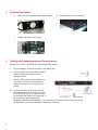
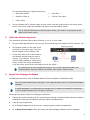
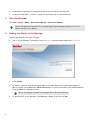
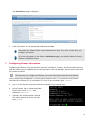
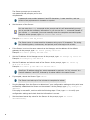
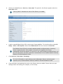
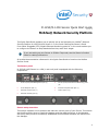
M-1250/M-1450 Sensor Quick Start Guide
Revision B
McAfee® Network Security Platform
This Quick Start Guide explains how to quickly set up and activate your McAfee® Network
Security Platform M-1250/M-1450 Sensor in in-line mode. Cabling the Sensor's Small
Form-factor Pluggable (SFP) Gigabit Ethernet Monitoring ports for in-line mode enables you
to configure the Sensor to drop attacks before they reach their target.
If you are setting up your Sensor in SPAN or Tap mode, see the Sensor's Product
Guide for cabling instructions.
All product documentation referenced in this Quick Start Guide is found on the McAfee
Service Portal.
The Sensor panel
M-1250/M-1450 Sensor is a 1RU (1 rack unit) and is equipped with the following
components:
1
RJ-45 10/100/1000 Management port (1)
5
RJ-45 10/100/1000 Ethernet Monitoring ports
(8)
2
RJ-45 Response port (1)
6
External Compact Flash port (1)
3
RS-232C Console port (1)
7
Power supply A (1)
4
RS-232C Auxiliary port (1)
Sensor setup overview
This section explains how to position and cable the various ports of your Sensor. This section
also briefly explains how to install the Manager and then add the Sensor to the Manager,
and verify that you have successfully established communication between the Sensor and
the Manager.
1
1
2
Position the Sensor
a
Keep the mounting ears and screws ready.
c
Install the Sensor into a rack.
b
Attach the ears to the Sensor.
Cabling the Management and Console ports
Ensure the Sensor is powered OFF before attaching cables.
2
a
Plug a Category 5e Ethernet cable in the Mgmt port.
b
Plug the other end of the cable into the
network device connected to your
Manager server.
c
Plug the DB9 Console cable supplied in
the Sensor box into the Console port
(labeled Console on the Sensor front
panel).
d
Connect the other end of the Console
port cable directly to a COM port of the
PC or terminal server you will be using
to configure the Sensor (for example, a
PC running correctly configured
Windows HyperTerminal software). You must connect directly to the console for initial
configuration; you cannot configure the Sensor remotely.
The required settings for HyperTerminal are:
e
•
Baud rate: 38400
•
Stop Bits: 1
•
Number of Bits: 8
•
Control Flow: None
•
Parity: None
Plug the female end of a power cable into the power inlet and plug the other end into a power
source. The Sensor ships with standard US power and international cables.
The M-1250/M-1450 does not have a power switch; you need to only plug the power
cable into a power source.
3
Cable the Monitoring ports
This procedure describes how to cable a Sensor to run in In-Line mode.
a
Plug the cable appropriate for use into one of the Monitoring ports labeled xA (for example, 1A).
b
Plug another cable into the peer of the
port used in the earlier step. This port
will be labeled xB (for example, 1B).
c
Connect the other end of each cable to
the network devices that you want to
monitor. (For example, if you plan to
monitor traffic between a switch and a
router, connect the cable connected to
1A to the router and the one connected to 1B to the switch.)
For instructions on how to cable the Sensor to run in other operating modes, see
McAfee Network Security Platform M-1250/M-1450 Sensor Product Guide.
4
Install the Manager Software
For detailed instructions, refer to McAfee Network Security Platform Installation Guide.
You must have administrator privileges on the target Windows server to install the Manager
software.
A MySQL database is included with the Manager and is installed (embedded) automatically
on your target Windows server during this process.
Following steps briefly explain the Manager installation:
a
Prepare the system according to the requirements outlined in McAfee Network Security Platform
Installation Guide and the Network Security Platform Release Notes.
b
Close all open applications.
c
Go to McAfee Update Server and log on, using the grant number and password.
d
Go to Manager Software Updates folder and select the latest Manager software version available.
3
5
e
Download the zip file to the target Windows server and extract the setup file.
f
Double-click Manager_<version>_setup.exe and follow the on screen prompts.
Start the Manager
Click Start | Programs | McAfee | Network Security Manager | Network Security Manager.
You do not require a license file for using Manager/Central Manager version 5.1.17.2 or
above, and 6.0.7.x or above.
6
Adding the Sensor to the Manager
The Manager displays the Login ID page.
a
Log on to the Manager. The default Login ID is admin and the default Password is admin123.
b
Click Configure.
c
An add-on license is required to enable NAC on M-series Sensors. To import and assign an
add-on license, go to Device List | Add-On Licenses page. For more information, see McAfee Network
Security Platform Installation Guide.
You do not require a license file to enable IPS on M-series Sensors.
d
4
To add a Sensor in the Manager, click Device List | Devices, and then click New.
The Add New Device page is displayed.
e
Enter information in the appropriate fields and click Save.
Remember the Shared Secret value entered at this step. This value is used while you
configure the Sensor.
For more information on the fields in Add New Device page, see McAfee Network Security
Platform Installation Guide.
7
Configuring Sensor information
Configuring the Sensor involves specifying network information, a name, and the shared secret key
that the Sensor uses to establish secure communication with the Manager. Use the same name and
key values set earlier.
The first time you configure the Sensor, you must have physical access to the Sensor.
At any time during configuration, you can type a question mark (?) to get help on the Sensor
command-line interface (CLI) commands. For a list of all commands, type commands.
a
Log on to the Sensor using the terminal connected to the Console port.
b
At the prompt, log on using the default
Sensor user name (admin) and
password (admin123).
c
Optional, but recommended—Change
the Sensor password. At the prompt,
type: passwd.
5
The Sensor prompts you to enter the
new password and prompts you for the
old password.
A password must contain between 8 and 25 characters, is case-sensitive, and can
consist of any alphanumeric character or symbol.
d
Set the name of the Sensor:
You can enter the setup command at the prompt and this will automatically prompt
you to provide the necessary information or you can use the set command instead. If
you use the set command, you must manually enter the complete command syntax.
Example: At the prompt, type: set sensor name <word>.
Example: set sensor name HR_sensor1
The Sensor name is a case-sensitive character string up to 25 characters. The string
can include hyphens, underscores, and periods, and must begin with a letter.
e
If the Sensor is not on the same network as the Manager, set the address of the default
gateway. At the prompt, type: set sensor gateway <A.B.C.D>.
Example: set sensor gateway 192.168.3.68
f
Set the IP address of the Manager server. At the prompt, type: set manager ip <A.B.C.D>.
Example: set manager ip 192.168.2.8
g
Set the IP address and subnet mask of the Sensor. At the prompt, type: set sensor ip
<A.B.C.D> <E.F.G.H>.
Example: set sensor ip 192.168.2.12 255.255.255.0
Specify an IP address using four octets separated by periods: X.X.X.X, where X is a
number between 0 and 255, followed by a subnet mask in the same format.
h
If prompted, reboot the Sensor. Type: reboot.
The Sensor can take up to five minutes to complete its reboot.
i
Ping the Manager from the Sensor to determine if your configuration settings to this point have
successfully established the Sensor on the network. At the prompt, type: ping <manager IP
address>.
If the ping is successful, continue with the following steps. If not, type show to verify your
configuration settings and check that the information is correct.
j
6
Set the shared secret key value for the Sensor. At the prompt, type: set sensor
sharedsecretkey.
The Sensor then prompts you to enter the shared key value and confirm the same.
This value is used to establish a trust relationship between the Sensor and the
Manager. The secret key value can be between 8 and 25 characters of any ASCII text.
The shared key value is case-sensitive.
Make sure the value matches the shared secret key value you provided in the Manager
interface.
8
k
To verify the configuration information, type show. Check that all information is correct.
l
To exit the session, type exit.
Verify successful installation
A handshake process begins between the Sensor and the Manager. The devices will take a few
seconds to establish communication.
Perform the following steps to verify successful communication between the Sensor and the Manager.
a
In the Sensor CLI, type: status.
7
The status report appears
b
Return to the Manager. In the Manager Home page, view the Manager status in the System Health
section.
Manager status should be up and Sensor status should be active.
c
8
From the Manager Home page, click Configure to open the Configuration page.
d
Select your added Sensor: Device List | Sensor_Name. The ports for this Sensor appear under the
Sensor_Name node.
"Device_Name" indicates the name of the Sensor you added.
e
A policy named Default Inline IPS is active upon Sensor addition. To view this policy, select IPS
Settings | Policies | IPS Policy Editor. Now select Default Inline IPS from the list and click View / Edit.
The Default Inline IPS policy contains attacks already configured with a "blocking"
Sensor response action; if any attack in the policy is triggered, the Sensor
automatically blocks the attack. To tune this or any other McAfee-provided policies, you
can clone the policy and then customize it as described in the McAfee Network Security
Platform IPS Administration Guide.
f
Click Device List | Device_Name | Port Settings.
For more information on port settings, see Configuration Sensor monitoring and
response ports, McAfee Network Security Platform IPS Administration Guide.
g
Click the button representing the ports on the Sensor that you cabled. Ensure that your port
settings match the cabling (for example, In-line mode).
9
9
You're up and running!
Your Sensor is actively monitoring connected segments and communicating with the Manager for
administration and management operations.
a
Read McAfee Network Security Platform Quick Tour for an overview of the system. For detailed
usage instructions, see McAfee Network Security Platform Installation Guide and McAfee Network
Security Platform IPS Administration Guide, or click the Detailed Help buttons in the upper-right
corner of each window in the Manager.
b
Launch the Threat Analyzer from the Home page to view alert statistics as attacks are detected.
These will display in the Unacknowledged Alert Summary area of the Manager Home page.
c
Having problems? Check McAfee Network Security Platform Troubleshooting Guide for
troubleshooting information.
d
Note that most deployment problems stem from configuration mismatches between the Sensor
and the network devices to which it is connected. Check your duplex and auto-negotiation
settings on both devices to ensure they are synchronized.
If you need to contact Technical Support, go to https://mysupport.mcafee.com.
10
11
Copyright © 2014 McAfee, Inc. www.intelsecurity.com
Intel and the Intel logo are trademarks/registered trademarks of Intel Corporation. McAfee and the McAfee logo are trademarks/
registered trademarks of McAfee, Inc. Other names and brands may be claimed as the property of others.
12
700-3596B00