1
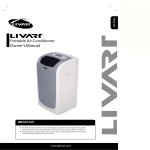
PORTABLE
AIR CONDITIONER
OWNER'S MANUAL
Models
MPF-12CR
Thank you for
purchasing this
product.
Please read this
Owner's Manual
carefully before
operating.
Table of Contents.................................. ......................1
CONTENTS
1.SAFETY RULES............................................................................. 1
2.NAMES OF PARTS.......................................................................... 2
3.ACCESSORIES................................................................................ 2
4.OPERATION PANEL OF THE AIR CONDITIONER........................ 3
5.OPERATING INSTRUCTION FOR THE AIR CONDITIONER ........ 4
6.INSTALLATION............................................................................... 6
7.MAINTENANCE............................................................................... 7
8.TROUBLE SHOOTING.................................................................... 8
9.REMOTE CONTROLLER........................................................... 9-13
10.GUARANTEE................................................................................14
SAFETY RULES
1. DO NOT CONNECT UNIT TO ANY AC SOCKET IN DISREPAIR OR WITH
CONNECTIONS.
2. DO NOT USE IN THE FOLLOWING LOCATIONS:
- NEXT TO SOURCE OF FIRE.
- AN AREA WHERE OIL IS LIKELY TO SPLASH.
- AN AREA EXPOSED TO DIRECT SUNLIGHT.
- AN AREA WHERE WATER IS LIKELY TO SPLASH.
- NEAR A BATH, ASHOWER OR A SWIMMING POOL
- IN THE GREEN HOUSE
3. NEVER INSERT YOUR FINGERS OR ANY FOREIGN OBJECTS INTO THE AIR
OUTLET. TAKE SPECIAL CARE TO WARN CHILDREN OF THESE DANGERS.
4. ALWAYS STORE THE UNIT UPRIGHT IN ORDER TO MAINTAIN THE COMPRESSOR IN A PROPER CONDITION.
5. BE SURE TO UNPLUG THE UNIT BEFORE CLEANING.
6. THE HEATER MUST NOT BE LOCATED IMMEDIATELY BELOW A SOCKET
OUTLET.
7. IF THE APPLIANCE IS COVERED, THERE IS A RISK OF OVERHEAT.
8. IF THE SUPPLY TOOL OF THIS APPLIANCE IS DAMAGED, IT MUST BE
REPLACED BY A REPAIR SHOP APPOINTED BY THE MANUFACTURER,
BECAUSE SPECIAL PURPOSE TOOLS ARE REQUIRED.
NOTE: The air-conditioner can be connected only to a supply with system
impedance no more than 0.4582 ohm. In case necessary, please consult your
supply authority for system impedance information.
1
NAMES OF PARTS
OPRATION PANEL
REAR COVER
AIR INLET
FRONT COVER
AIR OUTLET
AIR OUTLET
OUTDOOR
WATER PUMP
DRAIN HOSE
AIR INLET
OUTDOOR
REMOTE CONTROLLER
CASTER
INDOOR
CONTINUOUS
DRAIN HOSE
POWER CORD
SIDE VIEW
FRONT VIEW
AIR INLET
OUTDOOR
REAR VIEW
Fig.1
ACCESSORIES
PARTS :
PARTS NAME :
QUANTITY :
DUCT
1
ADAPTOR A (FOR PERMANENT DUCT
1
MOUNTING)
ADAPTOR B (FOR TEMPORARY DUCT
MOUNTING)
1
WALL PLUG
4
SCREWS
4
ALKALINE BATTERIES
2
REMOTE CONTROLLER
1
WATER PUMP DRAIN HOSE
1
Fig.2
Check all the accessories are included in the package and please refer to the installation instructions
for their usage.
2
OPERATION PANEL OF THE AIR CONDITIONER(COOLING AND HEATING)
DIGITAL DISPLAY
FAN SPEED INDICATOR
COOL/DRY/FAN/HEAT INDICATIOR
Green lamp will light when the mode is selected
WATER FULL INDICATOR
Red lamp will blink when the tank is full
TEMP SETTING BUTTON
Press your desired room temperature
setting by pressing the button
(up)
or button
(down)
POWER INDICATOR
INFRARED
SIGNAL RECEIVER
POWER BUTTON
Turn on/off the unit
MODES BUTTON
Select the operation mode
from COOL.DRY.FAN.HEAT
TIMER ON/OFF INDICATOR
FAN SPEED BUTTON
Select the fan speed from
HIGH.MED or LOW
TIMER ON/OFF BUTTON
Program the on/off timer function
OPERATING PANEL
Fig.3
OPERATION PANEL OF THE AIR CONDITIONER(COOLING ONLY TYPE)
DIGITAL DISPLAY
FAN SPEED INDICATOR
COOL/DRY/FAN INDICATOR
Green lamp will light when the mode is selected
WATER FULL INDICATOR
Red lamp will blink when the tank is full
TEMP SETTING BUTTON
Select your desired room temperature
setting by pressing the button
(up)
or button
(down)
POWER INDICATOR
INFRARED
SIGNAL RECEIVER
POWER BUTTON
Turn on/off the unit
MODES BUTTON
Select the operation mode
from COOL.DRY.FAN.
TIMER ON/OFF INDICATOR
FAN SPEED BUTTON
Press the button to select
the fan speed from
HIGH.MED or LOW
TIMER ON/OFFBUTTON
Program the on/off timer function
OPERATING PANEL
Fig.4
3
OPERATING INSTRUCTING FOR THE AIR CONDITIONER
Before Starting This Unit
1) Select a suitable location, make sure you have easy access to an electrical outlet.
2) Install the Flexible Exhaust Hose and the Adjustable Window Slider Kit as depicted in Fig.5 &
Fig.5a
Fig.5a
Fig.5
NOTE: Step 2 is required only while using the cooling mode
3) Plug the unit into a 115V~60Hz grounded electrical outlet.
4) Make sure the water pump drain hose is correctly installed.
¡¡ 5) Press the on / off button to turn on the unit.
Water pump drain hose
Fig.6
1 BEFORE USE
Dehumidifying and Cooling Operations
- The operating range for cooling operating is 17OC-30OC/63OF-86OF.
- If the cooling or dehumidifying operations have been switched off and need switching on again
in a short time, allow approximately three minutes for the cooling or dehumidifying operations
to resume.
- Make sure the water pump drain hose is correctly connected to the unit.
Power supply:
- Insert the AC Power Plug to a AC socket.
- Do not connect the air conditioner to a multiple socket outlet which is also being used for other
electrical appliance.
- Be sure the power supply is AC 115V~ 60Hz.
4
O
O
O
O
2 COOLING OPERATION (Operating temperature range: 17 C-32 C/63 F-90 F)
- Press the "MODE" button several times until the "COOL" indicator light comes on.
- Press the "TEMP SETTING" buttons " " or " " to select your desired room temperature.
(17OC-30OC/63OF-86OF)
- Press the "FAN SPEED" button to choose the fan speed.
O
O
O
O
3 DEHUMIDIFYING OPERATION (Operating temperature range: 13 C-32 C/55 F-90 F)
- Press the "MODE" button several times until the "DRY" indicator light comes on.
- The fan will run at a fixed speed at this setting.
- Keep windows and doors closed for the best dehumidifying effect.
- Do not put the duct to window.
4 HEATING OPERATION (Cooling only type without heat feature)
O
O
O
O
(Operating temperature range:5 C-30 C/41 F-86 F)
- Press the "MODE" button several times until the "HEAT" indicator light comes on.
- Press the "TEMP SETTING" buttons " " or " " to select your desired room temperature.
(17OC-30OC/63OF-86OF)
- Press the "FAN SPEED" button to choose the fan speed.
- Do not put the duct to window.
5 FAN OPERATION
- Press the "MODE" button several times until the "FAN " indicator light comes on.
- Press the "FAN SPEED" button to choose the fan speed.
- Do not put the duct to window.
6 TIMER OPERATION
Setting the on timer:
- Press the "TIMER ON" button when the air conditioner is off. Select the time you need the unit
start to operate.
- The Operation Paned Window will display "ON"
- The starting time is adjustable from 0.00 to 24.
Setting the off timer:
- Press the "TIMER OFF" button when the air conditioner is on. Select the time you need the unit
turn off. The Operation Panel Window will display "OFF".
- The turning off time is adjustable from 0.00 to 24.
7 WATER PUMP DRAINAGE
- Connect the water pump drain hose to the unit before operate. When the water level of the internal
water tank reaches a predetermined level, the water pump will be activated and drain the
condensed water outside through the connected drain hose. The maximum delivery lift is 3.5m.
(Under this condition, attach the rubber blockage to the back hole to prevent continuous drainage.)
8 CONTINUOUS DRAINAGE
- When you plan to leave this unit unused for a long time, remove the rubber blockage form the back
hole and attach a section of the continuous drain hose to drain hose connector. All the water in the
water tank would drain outside through the drain hose. (Under this condition, the water pump is not
activated.)
5
INSTALLATION
1 IMPORTANT:
Install the mobile air conditioner in a flat and spacious location
where the air outlets will not be covered up. A minimum
clearance of 11.8in from a wall or other obstacles should
be kept. The appliance shall not be used in the laundry.
The plug shall accessible after appliance is positioned.
Wiring shall be done according to National rules.
11 .8
1 in
.
11
81
in
Fig.7
2 DUCT MOUNT INSTRUCTIONS:
Exhaust Air Oulet
Duck
Fig.8
A) TEMPORARY1. Attach one end of the duct to the exhaust air outlet of the
mobile air conditioner, first fit the left side of the duct on the
exhaust air panel, then the right side duct. Push it
downwards, be sure to fix thoroughly. (See the Fig.8)
2. Attach the other end of the duct to adaptor B.
3. Put the end of duct to a nearby window.
B) PERMANENT1. Attach one end of the duct to the exhaust air outlet of the
mobile air conditioner. According to the arrow direction,
first fit the left side of the duct on the exhaust air panel,
then the right side duct. Push it downwards, be sure to fix
thoroughly. (See the Fig.7)
2. Install the adaptor A onto the wall by using 4 wall plug and
screws, be sure to fix thoroughly. (See the Fig.9)
3. Attach the other end of the duct to adaptor A.
4. Cover the hole using the adaptor cap when not in use.
Adapter A
Skruer
Rawlplugs
max 47.25in
min 11.81in
Fig.9
The duct can be compressed or extended between 20in
and 80in, but it is desirable to keep the duct length to a
minimum.
IMPORTANT:
DO NOT OVER BEND THE DUCT (SEE Fig.10)
6
Fig.10
Window Kit Installation
Your window kit has been designed to fit most standard
Vertical and horizontal window applications, However, it
may be necessary for you to improvise/modify some aspects
of the installation procedures for certain types of window.
Please refer to Fig. 11 & Fig. 11a for minimum and maximum
window openings.
Drain Tank Safety Feature
This unit is equipped with a internal water tank, two full-safe
switch mechanisms, one is used to control the water pump
drainage, the other is used to monitor the water level inside
the internal water tank. When the water level reaches a
predetermined level, the full-safe switch mechanism is
activated. The digital display shows P1 and the water full
indicator light illuminates. Carefully move the unit outside,
remove the rubber blockage from the back drainage hole
and drain the water off. The unit will continue operating
properly.
MAINTENANCE
Horizontal
window
Window Slider Kit
Minimum:67.5cm(2.22ft).
Maxmum:123cm(4.04ft).
Fig.11
Horizontal
window
Window Slider Kit
Minimum:67.5cm(2.22ft).
Maxmum:123cm(4.04ft).
Fig.11a
IMPORTANT:
1) BE SURE TO UNPLUG THE UNIT BEFORE CLEANING.
2) DO NOT USE GASOLINE, THINNER OR OTHER CHEMICALS TO CLEAN THE UNIT.
3) DO NOT WASH THE UNIT DIRECTLY UNDER A TAP OR USING A HOSE. THE ELECTRICAL
CAUSE DANGER.
4) IF THE POWER CORD IS DAMAGED, IT SHOULD BE REPAIRED BY MANUFACTURE OR ITS
AGENCY.
1 AIR FILTER
- Clean the air filter at least once every two weeks to
prevent interior fan operation because of dust.
- Removal
Pull out the filter cover and remove the air filter from the
filter cover.
- Cleaning
Wash the air filter by immersing it gently in warm water
(about 40OC/104OF) with a neutral detergent. Rinse the
filter and dry it in a shady place.
- Mounting
Attach the air filter to the filter cover using the attachment
hooks on the inner surface of the cover. Put the filter cover
back to the unit.
2 UNIT ENCLOSURE
- Use a lint-free cloth soaked with neutral detergent to clean
the unit enclosure. Finished by a dry clean cloth.
Fig.12
7
TROUBLE SHOOTING
TROUBLES
POSSIBLE CAUSES
SUGGEST REMEDIES
1. UNIT DOES NOT
- Water full indicator blinks, water tank
Dump the water in the water tank.
START WHEN
is full.
PRESSING 1/0 BUTTON
- Room temperature is higher than
Reset the temperature.
the set temperature.(Heating mode)
- Room temperature is lower than
Reset the temperature.
the set temperature.(Cooling mode)
2. NOT COOL ENOUGH
- The windows or doors in the room
are not closed.
- There are heat sources inside the
Make sure all the windows and
doors are closed.
Remove the heat sources if possible.
room.
- Exhaust air duct is not connected or
blocked.
3. POWER SHUT OFF AT
HEATING MODE
Connect the duct and make
sure it can function properly.
- Temperature setting is too high.
Decrease the set temperature.
- Air filter is blocked by dust.
Clean the air filter.
- The automatic over heat protection
Switch on again after the unit has cool down.
function. When the temperature at
the air outlet exceed 70OC/158OF,the
device will stop.
4. NOISY OR VIBRATION
- The ground is not level or not flat
enough.
5. GURGLING SOUND
- The sound comes from the flowing
of the refrigerant inside the
air-conditioner.
8
Place the unit on a flat, level
ground if possible.
It is normal.
,
OWNER S MANUAL
REMOTE CONTROLLER
FOR PORTABLE AIR CONDITIONER
SET TEMPERATURE( C /F )
AUTO
COOL
DRY
HEAT
FAN
HIGH
MED
LOW
TEMP
MODE
ON/OFF
FAN
SPEED
TIMER
ON
TIMER
OFF
RESET LOCK
9
CONTENTS
1.Warning------------------------------------------------------------------------------------------------ 10
2.Remote Controller Specifications------------------------------------------------------------ 11
3.Performance Features--------------------------------------------------------------------------- 11
4.Introduction of Function Buttons on the Remote Controller----------------------- 11
5.Names and Functions of indicators on Remote Controller-------------------------- 12
6.Operating of the Remote Controller--------------------------------------------------------- 12
Note:
1. This operating manual is applicable to the following models of remote controller: R51H, R51H/C
2. Model R51H is used for cooling & heating type or heating pump type air conditioner.
Model R51H/C is used for cooling only type air conditioner.
Warning
1. Be sure there are no barriers between the remote controller and the receiver of indoor unit
otherwise the air conditioner will not work.
2. Keep the Remote Controller away from all liquids.
3. Protect the Remote Controller from high temperatures and exposure to radiation.
4. Keep the indoor receiver out of direct sunlight or the Air Conditioner may malfunction.
5. Keep controller away from EMI (Electro-Magnetic Interference) supplied by other household
appliances.
10
Remote Controller Specifications
Model
R51H, R51H/C
Rated Voltage
3.0V
Lowest Voltage of CPU
Emitting Signal
2.0V
Reaching Distance
Signal Range
8m
Environment
-5 C 60 C(-41OF~140OF)
~
Performance Feature
1. Operating Mode: COOL
HEAT
DRY
FAN and AUTO.
2. Timer Setting Function in 24 hours.
3. Indoor Setting Temperature Range : 17 C~30 C.(63OF ~86OF)
4. LCD (Liquid Crystal Display) of all functions.
5. Control function of charactron tube
Introduction of Function Buttons on the Remote Controller
1
TEMP Button
2
MODE Select Button: Each time you push the button, a mode is selected in a sequence
that goes from AUTO COOL DRY HEAT and FAN, as the following figure:
AUTO
: Push the button to decrease the indoor temperature setting.
COOL
DRY
HEAT
FAN
SET TEMPERATURE( C /F )
NOTE: HEAT only for Heat Pump
3
RESET Button: When the RESET button is pushed, all of the current
settings are cancelled and the control will return to the initial settings.
4
LOCK Button: Push this button to lock in all the current settings.
To release settings, push again.
AUTO
COOL
DRY
HEAT
FAN
HIGH
MED
LOW
TEMP
1
MODE
ON/OFF
TIMER
ON
5
2
5
6
TIMER ON Button: Press this button to preset the time ON(start to operate).
Each press will increase the time ON setting in 30 minutes increments.
When the setting time displays 10:00, each press will increase the time ON
setting in 60 minutes increments. To cancel the time ON program, simply
adjust the time ON to 0:00.
9
7
FAN
SPEED
TIMER
OFF
6
8
RESET LOCK
3
TIMER OFF Button: Press this button to preset the time OFF (turn off the operation).
Each press will increase the time OFF setting in 30 minutes increments. When the
setting time displays 10:00, each press will increase the time OFF setting in 60 minutes
increments. To cancel the time OFF program, simply adjust the time OFF to 0:00
4
Fig. 1
7
ON/OFF Button: Push this button to start the unit operation, push the button again to stop the unit operation.
8
FAN SPEED Button: This button is used for setting Fan Speed in the sequence that goes from AUTO LOW
MED to HIGH, then back to Auto.
9
TEMP Button
: Push the button to increase the indoor temperature setting.
11
Names and Functions of indicators on Remote Controller
1
2
3
4
TRANSMISSION Indicator: This indicator lights when remote controller
transmits signals to indoor unit.
1
2
MODE Display: Shows the current operation modes-- AUTO, COOL,
DRY , HEAT and FAN. HEAT only available for heat pump model.
HEAT PUMP ONLY - LOCK display is displayed by pushing the
LOCK button. Push the LOCK button again to clear display.
TIMER Display: This display area shows the settings of TIMER. That is,
if only the starting time of operation is set, it will display the TIMER ON.
If only the turning off time of operation is set, it will display the TIMER OFF.
If both operations are set, it will show TIMER ON OFF which indicates you
have chosen to set both the starting time and off time.
Display Panel
6
5
FAN
HIGH
MED
LOW
AUTO
COOL
DRY
HEAT
3
5
FAN Display: When the FAN button is pushed, this signal indicator lights.
6
Digital Display Area: This area will show the temperature and, if in the TIMER mode,
will show the ON and OFF settings of the TIMER.
4
Fig. 2
NOTE: All items are shown in the Fig.2 for the purpose of clear presentation But during the actual operation
only the relative functional items are shown on the display panel.
Operating of the Remote Controller
Install / Replace Batteries
The Remote Controller uses two alkaline dry batteries(R03/Ir03X2).
1. To install batteries, slide back the cover of the battery compartment and install the batteries
according to the directions (+and -) shown on the Remote Controller.
2. To replace the old batteries , use the same method as mentioned above.
NOTE
1. When replacing batteries, do not use old batteries or a different type battery. This may cause the
remote controller to malfunction.
2. If you do not use the remote controller for several weeks remove the batteries. Otherwise battery
leakage may damage the remote controller.
3. The average battery life under normal use is about 6 months.
4. Replace the batteries when there is no answering beep from the indoor unit or if the Transmission
Indicator light fails to appear.
AUTOMATIC OPERATION
When the Air Conditioner is ready for use, switch on the power and the OPERATION indicator lamp on the
display panel of the indoor unit starts flashing.
1. Use the MODE select button to select AUTO.
2. Push the TEMP button to set the desired room temperature. The most comfortable temperature settings
are between 21 C/70OF to 28oC/82OF
3. Push the ON/OFF button to start the air conditioner. The OPERATION lamp on the display panel of the
indoor unit lights. The operating mode of AUTO FAN SPEED is automatically set and there are no
indicators shown on the display panel of the remote controller.
4. Push the ON/OFF button again to stop the unit operation.
NOTE
1. In the AUTO mode, the air conditioner can logically choose the mode of COOL, FAN, HEAT and DRY by sensing
the difference between the actual ambient room temperature and the set temperature on the remote controller.
2. If the AUTO mode is not comfortable for you , the desired mode can be selected manually.
12
COOL , HEAT, and FAN ONLY Operation
1. If the AUTO mode is not comfortable , you may manually override the settings by using COOL, DRY,
HEAT(HEAT PUMP units only), or FAN ONLY modes.
2. Push the TEMP button to set the desired room temperature. When in COOLING mode, the most
comfortable settings are 21 C/70OF or above. When in HEATING mode, the most comfortable settings
are 28oC/82OF or below.
3. Push the FAN SPEED to select the FAN mode of AUTO, HIGH, MED or LOW.
4. Push the ON/OFF button. The operation lamp lights and the air conditioner starts to operate per your
settings. Push the ON/OFF button again to stop this unit operation.
NOTE: The FAN ONLY mode cannot be used to control the temperature. While in this mode, only steps 1 3 and 4 may
be performed.
DRY OPERATION
1. Push the MODE button to select DRY.
2. Push the TEMP button to set the desired temperature from 21 C/70OF to 28oC/82OF.
3. Push the ON/OFF button. The operation lamp lights and the air conditioner starts to operate in
the DRY mode. Push the ON/OFF button again to stop this unit operation.
TIMER Operation
TIMER ON button can set the auto-on time of the unit. TIMER OFF button can set the auto-off time of the unit.
1. To set the starting time.
1.1 Push the TIMER ON button, then the remote controller shows TIMER ON , the last set time for the
starting operation and the signal "h" will be shown on the DIGITAL DISPLAY area. You are now ready
to reset the time to START the operation.
1.2 Push the TIMER ON button again to set desired unit start time.
1.3 After setting the TIMER ON ,there will be a one-half second delay before the remote controller transmits
the signal to the air conditioner. Then, after approximately another 2 seconds, the signal "h" disappears
and the set temperature will re-appear on the digital display.
2. To set the stopping time.
2.1 Push the TIMER OFF button and the remote controller will show TIMER OFF, the last set time for
the stopping operation and the signal "h" will be shown on the DIGITAL DISPLAY area. You are now
ready to reset the time of the STOP operation.
2.2 Push the TIMER OFF button again to set the time you want to stop the operation.
2.3 After setting the TIMER OFF ,there will be a one-half second delay before the remote controller transmits
the signal to the air conditioner. Then, after approximately another 2 seconds, the signal "h" disappears
and the set temperature will re-appear on the digital display.
3. Set the starting & stopping time
3.1 Push the TIMER ON button, the remote controller will show TIMER ON, the last set time for START
operation and the signal "h" will be shown on the DIGITAL display area. You are now ready to readjust
the TIMER ON to start the operation.
3.2 Push the TIMER ON button again to set the time you want to start the operation.
3.3 Push the TIMER OFF button, the remote controller will show TIMER OFF, the last set time for STOP
operation and the signal "h" will be shown on the DIGITAL display area. You are now ready to reset the
time to STOP operation.
3.4 Push the TIMER OFF button again to set the time you want to stop the operation.
3.5 After setting the TIMER, there will be a one-half second delay before the remote controller transmits the
signal to the Air Conditioner. Then, after approximately another 2 seconds, the set temperature will
re-appear on the digital display .
NOTE
1. Please reset the TIMER after cancelling the former time settings.
2. The setting time is relative time. That is the time set is based on the delay of the current time.
13