1
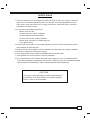
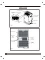
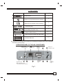
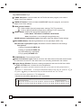
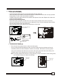
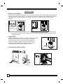
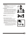
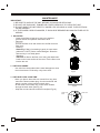
CONTENTS
1.SAFETY RULES............................................................................. 1
2.NAMES OF PARTS.......................................................................... 2
3.ACCESSORIES................................................................................ 3
4.OPERATION PANEL OF THE AIR CONDITIONER........................ 3
5.OPERATING INSTRUCTION FOR THE AIR CONDITIONER ........ 5
6.INSTALLATION............................................................................... 8
7.MAINTENANCE...............................................................................10
8.TROUBLE SHOOTING....................................................................11
NOTE
The rating data indicated on the energy label is based
on the testing condition of installing the un-extended
air exhaust duct without adaptor A & B (The duct and
the adaptor A & B are listed in the accessories chart
of the Instruction Manual).
SOCIABLE REMARK
The follow contents apply only the countries of Europe.
DISPOSAL: Do not dispose this product as unsorted municipal waste. Collection
of such waste separately for special treatment is necessary.
It is prohibited to dispose of this appliance in domestic household waste.
For disposal, there are several possibilities:
A) The municipality has established collection systems, where electronic waste can
be disposed of at least free of charge to the user.
B) When buying a new product, the retailer will take back the old product at least
free of charge.
C) The manufacture will take back the old appliance for disposal at least free of
charge to the user.
D) As old products contain valuable resources, they can be sold to scrap metal
dealers.
Wild disposal of waste in forests and landscapes endangers your health when
hazardous substances leak into the ground-water and find their way into the food
chain.
SAFETY RULES
1. This air conditioner has no ventilator for taking in fresh air from out of doors. You must
open doors or windows frequently when you use gas or oil heating appliances in the
same room, which consume a lot of oxygen from the air. Otherwise, there is a risk of
suffocation in extreme cases.
2. Do not use in the following locations:
- Next to source of fire.
- An area where oil is likely to splash.
- An area exposed to direct sunlight.
- An area where water is likely to splash.
- Near a bath, a shower or a swimming pool
- In the green house
3. Never insert your fingers or any foreign objects into the air outlet. Take special care to
warn children of these dangers.
4. Always store the unit upright in order to maintain the compressor in a proper condition.
5. Be sure to unplug the unit before cleaning.
6. The heater must not be located immediately below a socket outlet.
7. If the appliance is covered, there is a risk of overheat.
8. Do not operate this unit if it had a damaged cord or plug or if it is not working properly,
or has been dropped or damaged in any manner. Take the unit to the nearest authorized
service facility for examination, repair or electrical/mechanical adjustment.
CAUTION
If the supply cord is damaged, it must be replaced by the
manufacturer or its service agent or a similarly qualified
person in order to avoid a hazard.
1
NAMES OF PARTS
Operation Panel
Vertical Louver
Blade
Blades Control
Handle
Carrying Handle
(both side)
Water Tank
Horizontal Louver
Blade
Caster
Fig.1
Air Inlet (indoor)
Power Cord
Band
(insert)
Drain Plug
Air Outlet
outdoor
Power Cord
and Plug
Air inlet
outdoor
Fig.2
2
Bottom Drain Plug
ACCESSORIES
PARTS :
PARTS NAME :
QUANTITY :
Exhaust Duct
1
1
Adaptor A (for permanent duct mounting)
1
Adaptor B (for temporary duct mounting)
Expansion plug
4
Power Cord Band
(for bundling the power cord)
1
Drain Hose(Continuous drainage)
(Some models without)
1
Drain Hose(Connected with water tank)
1
1
Window Slider Kit
Check all the accessories are included in the package and please refer to the installation
instructions for their usage.
OPERATION PANEL OF THE AIR CONDITIONER
Timer on/off
indicator Lights
8
Digital Display
Mode
indicator
Lights
COOL DRY
TEMP. ADJUST
TIMER ON
TIMER OFF
F
HI
FAN
HEAT
MED
LO
7
4
MODE
Water Full
indicator Light
FULL
FAN SPEED
C
POWER
1
2
3
Signal receptor
(Not applicable to the
unit without remote control)
Fan speed
indicator
Lights
5
6
Power
indicator
Light
Fig.3
3
Key Pad Functions Fig.3
1 TIMER ON Button: Used to initiate the AUTO ON start time program, and used to
adjust Auto-Timer settings.
2 TIMER OFF Button: Used to initiate the AUTO OFF stop time program, and used to
adjust Auto-Timer settings.
3 TEMP. ADJUST Button :
: Used to adjust (forward) temperature settings(1oC/2oF increments).
: Used to adjust (backward) temperature settings(1oC/2oF increments).
4
MODE Button: Selects the appropriate operating mode:
COOL Mode --DRY Mode--FAN Mode--HEAT Mode
Note:"Heat Mode" is for Heating/Cooling Models only.
MODE Indicator Lights(Green light): Illuminates under the different mode settings.
5 FAN SPEED Button: Selects High-Medium-Low fan speeds(HI--MED--LO)
FAN Indicator Lights(Green light): Illuminates under the different mode settings:
Fan Options:
Cooling (3 speeds) HI--MED--LO.
Heating (3 speeds) HI--MED--LO.
Dry-Dehumidifying (1 speed) HI.
Fan (3 speeds) HI--MED--LO.
6 POWER Button: Power switch On/Off.
7 Water Full Indicator Light: Flashes red when the water level of the water tank exceeds
the maximum set level or if the water tank is not correctly positioned in the cabinet.
8 Digital Display Window: Shows the setting temperature and Auto-On/Off time. While
on DRY and FAN mode, it shows the room temperature.
Note: This appliance provides a feature that will allow you the option of setting temperatures in
Celsius
key pad &
or
Fahrenheit
key pad
. To change the temperature display on the main unit, press the
simultaneously
o
o
to alternate between the C & F scale.
o
.Celsius scale allows adjustments of 1 C increments.
Fahrenheit scale allows adjustment of 2oF increments.
Temperature Conversion Chart
O
C 10 11 12 13 14 15 16 17 18 19 20 21 22 23 24 25 26 27 28 29 30 31 32 33
O
F
4
48 50 52 54 56 58 60 62 64 66 68 70 72 74 76 78 80 82 84 86 88 90 92 94
OPERATING INSTRUCTING FOR THE AIR CONDITIONER
Before Starting This Unit
1) Select a suitable location, make sure you have easy access to an electrical outlet.
2) Install the Flexible Exhaust Hose and the Adjustable Window Slider Kit as depicted in Fig.4 &
Fig.4a
Fig.4
Fig.4a
NOTE: Step 2 is required only while using the cooling mode .
3) Plug the unit into a 220-240V~50Hz/ or 115V~ 60Hz (Refer to the nameplate located on
the right side of the unit.) grounded electrical outlet. DO NOT USE A REGULAR EXTENSION
CORD. If it is necessary to use an extension cord with this unit, use an approved air conditioner
extension cord only.
4) Insert the power cord fixing strap into the hole in the back of the unit, and bundle up the excess
cord.
5) Make sure the Water tank is correctly positioned inside the cabinet otherwise the unit will not
operate.
6) Press the POWER button to turn on the unit.
Electrical Requirement
1. All wiring must comply with local and national electrical codes and be installed by a qualified
electrician. If you have any questions regarding the following instructions, contact a qualified
electrician.
2. Check available power supply and resolve any wiring problems BEFORE installation and
operation of this unit.
3. For your safety and protection, this unit is grounded through the power cord plug when
plugged into a matching wall outlet. If you are not sure whether the wall outlets in your
home are properly grounded, please consult a qualified electrician.
4. The manufacturers nameplate is located on the right side panel of the unit and contains
electrical and other technical data specific to this unit.
5. To avoid the possibility of personal injury, always disconnect the power supply to the unit
before installing and/or servicing.
5
Operating Instructions
O
O
O
O
1 COOLING OPERATION (Operating temperature range: 17 C-32 C/62 F-92 F)
- Press the "MODE" button several times until the "COOL" indicator light comes on.
- Press the "TEMP ADJUST buttons " " or " " to select your desired room temperature.
The temperature can be set within a range of 17OC-30OC/62OF-88OF.
- Press the "FAN SPEED" button to choose the fan speed.
O
O
O
O
2 DEHUMIDIFYING OPERATION (Operating temperature range: 13 C-32 C/54 F-92 F)
- Press the "MODE" button several times until the "DRY" indicator light comes on.
- Under this mode, you cannot select a fan speed or adjust the temperature. The fan motor
operates at High speed.
- Keep windows and doors closed for the best dehumidifying effect.
- Do not put the duct to window.
CAUTION: During Cooling and dehumidifying modes, if the compressor cycle is interrupted
(unplugged, power failure, etc.) and reinstated immediately thereafter, a compressor
protection circuit is automatically self-affected. The compressor cannot operate during
a compressor protection condition. It may take about 3 minutes before the protection
circuit self-deactivates.(This is normal)
3 HEATING OPERATION (Cooling only type without heat feature)
O
O
O
O
(Operating temperature range:5 C-30 C/41 F-88 F)
-
Press the "MODE" button several times until the "HEAT" indicator light comes on.
Press the "TEMP ADJUST" buttons " " or " " to select your desired room temperature.
The temperature can be set within a range of 17OC-30OC/62OF-88OF.
Press the "FAN SPEED" button to choose the fan speed.
Do not put the duct to window.
4 FAN OPERATION
- Press the "MODE" button several times until the "FAN " indicator light comes on.
- Press the "FAN SPEED" button to choose the fan speed. The temperature cannot be adjusted.
- Do not put the duct to window.
5 TIMER OPERATION
Setting the on timer:
- Press the "TIMER ON" button when the air conditioner is off.
- Continue pressing or keep pressing the "TIMER ON " button to select the time you need the unit
start to operate. The time is programmed as :0.5-1.0-1.5-2.0-2.5-3.0-3.5-4.0-4.5-5.0-5.5-6.0-6.57.0-7.5-8.0-8.5-9.0-9.5-10-11-12-13-14-15-16-17-18-19-20-21-22-23-24-0.0
- The starting time is adjustable from 0.0 to 24.
Setting the off timer:
- Press the "TIMER OFF" button when the air conditioner is on.
- Continue pressing or keep pressing the "TIMER OFF " button to select the time you need the unit
stop operation. The time is programmed as :0.5-1.0-1.5-2.0-2.5-3.0-3.5-4.0-4.5-5.0-5.5-6.0-6.57.0-7.5-8.0-8.5-9.0-9.5-10-11-12-13-14-15-16-17-18-19-20-21-22-23-24-0.0
- The turning off time is adjustable from 0.0 to 24.
6
6
WATER TANK DRAINAGE
A) During Cooling Mode:
- Install the Flexible Exhaust Hose and the Adjustable Window Slider Kit .
- When the water level inside the internal tank reaches a predetermined level, the unit stop operation
automatically. The fan motor will continue to operate.
- Carefully remove the water tank from the cabinet and dispose of the water. Replace the water tank
back to its original position.
B) During Dehumidifying Mode:
- Remove the drain plug from the back of the unit and connect the drain hose, then connect the
other end of the drain hose to the water tank as depicted in Fig.5. So the condensed water will flow
into the internal tank through the drain hose.
- When the water tank is full, just pull it out and dispose of the water.
Remove the drain plug
from the back.
10mmMax
Fig.5
Remove the drain
plug and install the
drain hose.
7 CONTINUOUS DRAINAGE
- This unit also has provisions for a continuous drain option.
-
During Cooling and dehumidifying modes, remove the drain plug from the back of the unit,
install the continuous drain hose(some models not included) , then attach a section garden
hose (not included) to the drain hose connector. Place the open end of the hose directly over
the drain area in your basement floor. Please refer to Fig.6 & 6a.
Note: This drain method will reduce the cooling capacity, in order to maintain the best cooling effect,
you had better employ the water tank drainage.
Remove the
drain plug
Connect the
drain hose
Fig.6
Fig.6a
7
INSTALLATION
1. Window Kit Installation
Your window kit has been designed to fit most standard Vertical and horizontal window applications,
However, it may be necessary for you to improvise/modify some aspects of the installation procedures
for certain types of window. Please refer to Fig. 7 & Fig. 7a for minimum and maximum window
openings.
Horizontal
window
Horizontal
window
Window Slider Kit
Minimum:67.5cm(2.22ft).
Maxmum:123cm(4.04ft).
Window Slider Kit
Minimum:67.5cm(2.22ft).
Maxmum:123cm(4.04ft).
Fig.7a
Fig.7
Note: If the window opening is less than the above mentioned minimum length of the window slider
kit, cut that one with a hole in it short to fit for the window opening. Do never cut out the hole
in window slider kit.
2. IMPORTANT:
Install the mobile air conditioner in a flat and spacious location
where the air outlets will not be covered up. A minimum
clearance of 30cm from a wall or other obstacles should
be kept. The appliance shall not be used in the laundry.
The plug shall accessible after appliance is positioned.
Wiring shall be done according to National rules.
30c
m
30
3. DUCT MOUNT INSTALLATION:
Fig.9
8
Fig.8
cm
A) TEMPORARY1. Attach one end of the duct to the exhaust air outlet of the
mobile air condition, push it downwards, be sure to fix
thoroughly. (See Fig.9)
2. Attach the other end of the duct to adaptor B.
3. Put the end of duct to a nearby window.
Expansion plug
position
Adapter A
B) PERMANENT1. Attach one end of the duct to the exhaust air outlet of the
mobile air conditioner. According to the arrow direction,
push it downwards, be sure to fix thoroughly. (See Fig.9)
2. Install the adaptor A onto the wall by using 4 expansion
plugs and screws, be sure to fix thoroughly. (See Fig.10)
3. Attach the other end of the duct to adaptor A.
4. Cover the hole using the adaptor cap when not in use.
max 120CM
min 30CM
Fig.10
The duct can be compressed or extended moderately
according to the installation requirement, but it is
desirable to keep the duct length to a minimum.
IMPORTANT:
DO NOT OVER BEND THE DUCT (SEE Fig.11)
4. WATER TANK SAFETY FEATURE
This unit is equipped with a internal water tank. When the
water level reaches a predetermined level, the digital
display area shows P1 and the water full indicator
light flash(red). Carefully remove the water tank from the
cabinet and dispose of the water (See Fig.12). Replace the
water tank back to its original position. The red light will stop
flashing and P1 symbol will disappear. The unit will continue
operating properly.
Note: When drag the water tank out from the cabinet, please
do it slowly and slightly to prevent water splashing.
Any time when the water tank is removed/displaced,
and /or full of water, the water full indicator will flash red
and the digital display area show P1 .
Fig.11
Fig.12
9
MAINTENANCE
IMPORTANT:
1) BE SURE TO UNPLUG THE UNIT BEFORE CLEANING OR SERVICING.
2) DO NOT USE GASOLINE, THINNER OR OTHER CHEMICALS TO CLEAN THE UNIT.
3) DO NOT WASH THE UNIT DIRECTLY UNDER A TAP OR USING A HOSE. THE ELECTRICAL
CAUSE DANGER.
4) IF THE POWER CORD IS DAMAGED, IT SHOULD BE REPAIRED BY MANUFACTURE OR ITS
AGENCY.
1 AIR FILTER
- Clean the air filter at least once every two weeks to
prevent inferior fan operation because of dust.
- Removal
Pull out the filter cover and remove the air filter from the
filter cover.
- Cleaning
Wash the air filter by immersing it gently in warm water
(about 40OC/104OF) with a neutral detergent. Rinse the
filter and dry it in a shady place.
- Mounting
Attach the air filter to the filter cover using the attachment
hooks on the inner surface of the cover. Put the filter cover
back to the unit.
Fig.13
2 UNIT ENCLOSURE
- Use a lint-free cloth soaked with neutral detergent to clean
the unit enclosure. Finished by a dry clean cloth.
Fig.14
3 UNIT IDLE FOR A LONG TIME
-
-
When you plan to leave this unit unused for a long time,
remove the bottom rubber plug from the back hole and
attach a section of the continuous drain hose .
All the water in the bottom tray would drain outside
through the drain hose.(See Fig.15)
Wrap the cord and bundle it with the band(see Fig.16).
Fig.15
Power cord
band
Power cord
Fig.16
10
TROUBLE SHOOTING
TROUBLES
POSSIBLE CAUSES
SUGGEST REMEDIES
1. UNIT DOES NOT
- Water full indicator blinks, water tank
Dump the water in the water tank.
START WHEN
is full.
PRESSING POWER BUTTON
- Room temperature is higher than
Reset the temperature.
the set temperature.(Heating mode)
- Room temperature is lower than
Reset the temperature.
the set temperature.(Cooling mode)
2. NOT COOL ENOUGH
- The windows or doors in the room
are not closed.
- There are heat sources inside the
Make sure all the windows and
doors are closed.
Remove the heat sources if possible.
room.
- Exhaust air duct is not connected or
blocked.
3. POWER SHUT OFF AT
HEATING MODE
4. NOISY OR VIBRATION
- Temperature setting is too high.
Decrease the set temperature.
- Air filter is blocked by dust.
Clean the air filter.
- The automatic over heat protection
function. When the temperature at
O
O
the air outlet exceed 70 C/158 F,the
de vice will stop.
- The ground is not level or not flat
enough.
5. GURGLING SOUND
Connect the duct and make
sure it can function properly.
- The sound comes from the flowing
Switch on again after the unit has cool down.
Place the unit on a flat, level
ground if possible.
It is normal.
of the refrigerant inside the
air-conditioner.
6. COMPRESSOR DOES NOT
WORK AND THE DIGITAL
- The bottom tray is full
Remove the bottom drain plug and drain
the water outside.
DISPLAY AREA SHOWS
P2
11
LIVART, INC.
LIVART PORTABLE AIR CONDITIONER LIMITED WARRANTY- USA
LIVART, INC. warrants the accompanying LIVART 12000BTU (LPAC-12CRWGR) Portable Air Conditioner to be free of
defects in material and workmanship for the applications specified in its operation instruction for a period of ONE (1) year
from the date of original retail purchase in the United States.
If the air conditioner exhibits a defect in normal use, LIVART, INC. will, at its option, either repair or replace it, free of
charge within a reasonable time after the air conditioner is returned during the warranty period. After the warranty expires,
the customer must pay for service and parts if the unit has come to be serviced.
As a condition to any warranty service obligation, the consumer must present this Warranty Certificate along with a copy of
the original purchase invoice.
THIS WARRANTY DOES NOT COVER:
1) Damage, accidental or otherwise, to the air conditioner while in the possession of a consumer not caused by a
defect in material or workmanship;
2) Damage caused by consumer misuse, tampering, or failure to follow the care and special handling provisions in
the instructions.
3) Damage to the finish of the case, or other appearance parts caused by wear.
4) Filter.
5) Damage caused by repairs or alterations of the air conditioner by anyone other than authorized by LIVART, INC.
6) Freight and Insurance cost for the warranty service.
ALL IMPLIED WARRANTIES, INCLUDING ANY IMPLIED WARRANTY OF MERCHANTABILITY ARE LIMITED TO ONEYEAR DURATION OF THIS EXPRESS LIMITED WARRANTY. LIVART, INC. DISCLAIMS ANY LIABILITY FOR
CONSEQUENTIAL OR INCIDENTAL DAMAGES AND IN NO EVENT SHALL LIVART, INC.’S LIABILITY EXCEED THE
RETAIL VALUE OF THE AIR CONDITIONER FOR BREACH OF ANY WRITTEN OR IMPLIED WARRANTY WITH
RESPECT TO THIS AIR CONDITIONER
IF YOU HAVE ANY QUESTIONS REGARDING WARRANTY OR DEFECT CONCERNS PLEASE CONTACT US AT: Livart Inc. 2110 S. Tubeway Avenue Commerce, CA 90040 TEL: (323)887‐7750 FAX: (323)887‐7759 Website: www.lglivart.com Business Hours: Monday through Friday 9:00AM to 6:00PM