1
XL 1000 Series
FOR SMOKE CONTROL
HONEYWELL EXCEL 5000 OPEN SYSTEM
INSTALLATION AND COMMISSIONING INSTRUCTIONS
CONTENTS
Operational Environment ........................................ 14
General ............................................................................... 3
Before Installation ............................................................. 3
Installation ......................................................................... 3
Wiring ................................................................................. 4
XL1000 Series Power Consumption .............................. 5
I/O Modules ................................................................... 5
Description of the XL1000 Controller............................... 7
Overview........................................................................ 7
Terminal Blocks ............................................................. 8
LonWorks Interface........................................................ 8
Ethernet Interface .......................................................... 8
RS232C Serial Interface Ports....................................... 9
Port 1 (Factory Service Interface) ............................ 9
Port 2 (Browser Interface) ........................................ 9
Port 3 (Modem Interface) ......................................... 9
CF Port LED, Request Button, and Slot......................... 9
USB Interface Downloads.............................................. 9
LEDs and Buttons.......................................................... 9
LonWorks Service LED and Service Button ............. 9
Power Supply LED......................................................... 9
Binary Input (terminals 3+4) LED................................... 9
Binary Output (terminals 7+8) LED ................................ 9
Binary Output (terminals 9+10) LED ............................ 10
Ethernet LEDs ............................................................. 10
Ethernet Link LED .................................................. 10
Ethernet Activity LED ............................................. 10
LEDs L1 and L2 ........................................................... 10
Reset Button ................................................................ 10
Mounting .......................................................................... 10
Before Installation ........................................................ 10
Dimensions .................................................................. 10
DIN Rail Mounting/Dismounting ............................. 11
Wall/Panel Mounting/Dismounting ......................... 11
Swivel Cover Lock.................................................. 11
Power Supply................................................................... 12
Lightning Protection ..................................................... 14
Interfaces and Bus Connections .................................. 14
Technical Data............................................................. 14
System Data........................................................... 14
Copyright © 2008 Honeywell GmbH All Rights Reserved
LonWorks Communications ........................................... 14
General Information ..................................................... 14
Connecting to the LONWORKS Network......................... 14
Binary Input and Outputs................................................ 15
Wiring ........................................................................... 15
Binary Input .................................................................. 15
Binary Outputs ............................................................. 15
Hardware Limits...................................................... 15
Protocolling .................................................................. 15
XL1000 Configuration...................................................... 15
Smoke Control Configuration ....................................... 16
Data File Set-Up........................................................... 16
Panel Reset.................................................................. 16
Typical Power Limited Circuit for XL1000 .................... 17
Connecting Single Bus Controller Systems.................. 17
XL1000, I/O Modules on Single Rail....................... 17
XL1000, I/O Modules on Rails in Single Cabinet .... 17
I/O Modules in Separate Rooms............................. 18
LONWORKS Bus Topologies .......................................... 18
Mounting/Dismounting Modules .................................... 18
Mounting/Dismounting Sockets.................................... 18
Mounting Sockets ................................................... 18
Connecting Sockets................................................ 19
Dismounting Terminal Sockets ............................... 19
Mounting/Dismounting Electronic Modules .................. 20
Mounting Electronic Modules.................................. 20
Dismounting Electronic Modules ............................ 20
Connecting HMIs or Laptops........................................ 20
Connecting Laptops (XW-Online/CARE) ................ 20
Description of the I/O Modules ....................................... 21
Common Features ....................................................... 21
Analog Input Modules .................................................. 22
Types of Analog Input Modules .............................. 22
Features ................................................................. 22
Terminals................................................................ 22
XFL821AU Connection Examples .......................... 23
Analog Output Modules................................................ 24
Types of Analog Output Modules ........................... 24
Features ................................................................. 24
Terminals................................................................ 24
Technical Data........................................................ 24
EN1B-0409GE51 R0908A
General
XL1000
Modules with Manual Overrides..............................25
XFL822AU Connection Example ............................25
Synchronization Behavior of Analog Output Module
Configured as Floating Output ................................25
Binary Input Modules....................................................26
Types of Binary Input Modules................................26
Features..................................................................26
Terminals ................................................................26
Technical Data ........................................................26
Status LEDs ............................................................26
XFL823AU Connection Examples...........................27
Relay Output Modules ..................................................28
Types of Relay Output Modules..............................28
Features..................................................................28
Terminals ................................................................28
Permissible Loads...................................................29
Status LEDs with Manual Overrides .......................29
Connection Example...............................................30
Troubleshooting...............................................................31
Testing Wiring Connections..........................................31
I/O Modules Troubleshooting........................................31
Power LED of I/O Modules .....................................32
Service LED of I/O Modules....................................32
Trademark Information
Echelon, LON, LONMARK, LONTALK, LONWORKS, Neuron, are
trademarks of Echelon Corporation registered in the United
States and other countries.
EN1B-0409GE51 R0908A
2
XL1000
Installation
WARNING
This equipment generates, uses, and can radiate radio
frequency energy, and if not installed and used in accordance
with the instructions manual, may cause interference to radio
communications. It has been tested and found to comply with
the limits for a Class A computing device pursuant to Subpart
J of Part 15 of FCC Rules, which are designed to provide
reasonable protection against such interference when
operated in a commercial environment. Operation of this
equipment in a residential area is likely to cause interference,
in which case the user, at his own expense, will be required to
take whatever measures may be required to correct the
interference. Any unauthorized modification of this equipment
may result in the revocation of the owner’s authority to
continue its operation.
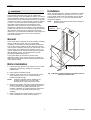
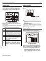
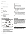
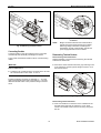
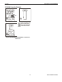
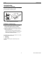
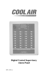
Mount controller subpanel in cabinet so all labeling is visible.
Secure full-size subpanel in place with six no. 10 x ½-inch
(13 mm) sheet metal screws (not supplied). Secure smaller
subpanel with four no. 10 x ½-inch (13 mm) sheet metal
screws (not supplied).
NOTE:
Subpanel must mount flat and should not bulge or
recess anywhere.
FULL-SIZE
CABINET
General
The XL1000 Series is designed to provide heating, ventilating
and air-conditioning control. They can operate either
standalone, or networked to Honeywell central workstations
such as EBI. These controllers can also be used for smoke
control system monitoring and control, for monitor and control
of fire (UL864), and general purpose signaling (UL2017). In
UL2017 applications, the product can be used as a type NM
(Non-Monitored) system. It is also approved for UL916
(Energy Management Equipment.)
The XL1000 Series can be used for smoke control
applications when used in conjunction with a UL-listed fire
alarm control panel (FACP) and UL-listed fire fighters’ smoke
control station (FSCS).
Before Installation
1. Unpack door and remove the XL1000 from carton. Check
equipment and report any damage to a Honeywell
representative.
2. Verify cabinet is installed correctly.
Fig. 1. Mounting controller subpanel in cabinet (full-size
subpanel cabinet shown)
3. Securely mount the XL1000 to a rigid structural surface
using at least four sets of 1/4 in. (6 mm) mounting
hardware (supplied locally).
NOTE:
SIX NO. 10 x ½-INCH (13 mm)
SHEET METAL SCREWS
Anchoring materials must be suitable for the
mounting surface (wood, concrete, steel).
Mounting must comply with all local codes.
4. Obtain correct number and type of sheet metal screws for
subpanel. Installation of a full-size subpanel requires six
no. 10 x ½-inch (13 mm) sheet metal screws (not
supplied). Installation of a smaller subpanel requires four
no. 10 x ½-inch (13 mm) sheet metal screws (not
supplied).
5. Obtain 14505159-001 Tamper Switch per job requirements. Installation of Tamper Switch is optional.
3
EN1B-0409GE51 R0908A
Wiring
XL1000
Wiring
WARNING
All wiring to the XL1000 controller is unsupervised, except as
noted.
All circuits are power limited, except for AC power circuits,
relay contacts and other circuits as noted.
Risk of electric shock or equipment damage!
► Subpanel and Controller power must remain OFF until
Controller is checked.
All field wiring terminals accept 24 AWG to 14 AWG
(0.25 mm2 to 2 mm2) conductors except as noted.
All wiring must conform to local codes, ordinances, and
regulations. Refer to job drawings for details.
Verify that the voltage difference between any conductor and
earth ground does NOT exceed 150 Vac.
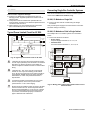
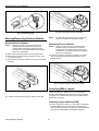
1. Connect input/output device wiring, LONWORKS Bus
transmission wiring, and 14507063 Power Cable to
Controller per job drawings. Fig. 2 and Fig. 3 show typical
controller wiring. Four Power Module models are available
(see Table 2).
2. Connect line voltage to Terminals H and N of the
14507287 Power Module. Connect a good earth ground to
Terminal G of the Power Module. Fig. 13 through Fig. 15
show typical power wiring.
3. For Power Modules -001 through -007, leave power to
Power Supply and Controller OFF. Connect 14507063
Power Cable from Controller to Power Module.
4. Install optional Tamper Switch on cabinet per instructions
in the cabinet installation instructions. Wire Tamper
Switch per job drawings.
5. Mount cabinet door.
CAUTION
Risk of electric equipment damage! Excessive static can
burn out equipment.
► Observe proper anti-static material handling practices
when installing or servicing PC parts and related
components.
► Observe proper equipment and body grounding practices.
► Discharge static electricity from your body before handling
parts.
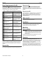
Table 1. Connector terminal specifications
connector terminal
pin
input /
output
signal type
voltage
type
max.
voltage
max. current
max.
frequency
max. line
impedance
analog input
AI
input
SIGNAL
±12 V
±20 mA
9600 baud
8K ohms
digital input
DI
input
SIGNAL
±10 V
±20 mA
--
15K ohms
SIGNAL
±10 V
±20 mA
9600 baud
8K ohms
10K ohms
analog output
AO
output
(1
(2
digital output
DO
output
AC/DC
±24 VAC/DC ±50 mA
--
totalizer output
TI
input
SIGNAL
±12 V
±12 mA
100 Hz
GND
--
--
--
--
--
signal ground
(1
special application;
(2
--
regulated
Table 2. Power module models
model
transformer max. input
Vac
current draw
Hz
(48 VA) controller
VAC output
14507287-001 120
0.5 A
60
24
14507287-002 120
1.7 A
60
24
accessory output
convenience outlet
120 Vac, 10A
24 Vac, 100 VA, 24 Vac, 40 VA
120 Vac, 10A
14507287-003 120
1.7 A
60
24
24 Vac, 100 VA, 24 Vdc, 600 mA
120 Vac, 10A
14507287-007 120
120 A
60
24
--
--
EN1B-0409GE51 R0908A
4
XL1000
Wiring
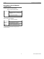
XL1000 Series Power Consumption
I/O Modules
When selecting the appropriate power supply, the power
consumption of the I/O modules must be taken into account.
I/O Modules
The XL1000 operates together with LONWORKS I/O modules
(dark-gray housings) with communication via LONWORKS
(FTT10-A, link power compatible) for easy integration and use
rd
with 3 -party controllers.
Table 3. XL1000 power consumption
max. power consumption
model
24 Vac, 60 Hz
24 Vdc
XL1000 with watchdog
load
500 mA
500 mA
Terminal Sockets
XL1000 without watchdog
load
500 mA
500 mA
The I/O modules are mounted on the appropriate terminal
sockets.
XFL821AU
130 mA
80 mA
Color Coding
XFL822AU, XFLR822AU
160 mA
90 mA
XFL823AU
180 mA
130 mA
To distinguish modules and components, the following color
coding is used:
XFL824AU, XFLR824AU
140 mA
90 mA
Table 4. Color coding of I/O Modules
color
5
part
red
All of the user-accessible adjustable
mechanical parts (i.e., bridge connectors and
locking mechanism) and operating controls
(manual overrides, etc.)
dark-gray
LONWORKS I/O modules
EN1B-0409GE51 R0908A
Wiring
XL1000
I/O Module Overview
Table 5. Overview of I/O modules and corresponding terminal sockets
LONWORKS I/O
module
description
inputs
outputs
manual
overrides
status
LEDs 1)
XFL821AU
Analog Input Module
8
–
–
–
XFL822AU
Analog Output Module
–
8
–
8
XFLR822AU
Analog Output Module
–
8
8
8
XFL823AU
Binary Input Module
12
–
–
12
XFL824AU
Relay Output Module
–
6 2)
–
6
XFLR824AU
Relay Output Module
–
6 2)
6
6
1)
2)
socket
scope of delivery
XS821-22
1 terminal socket,
1 bridge connector
1 swivel label holder
XS823
1 terminal socket,
1 bridge connector
1 swivel label holder
XS824-25
1 terminal socket,
1 bridge connector
1 swivel label holder
1 long cross connector
In addition to the power LED and service LED
Changeover outputs
ANALOG
INPUT
ANALOG
OUTPUT
BINARY
INPUT
XFLR822AU
LonWorks
I/O MODULES
XFL821AU
XFL822AU
RELAY
OUTPUT
XFLR824AU
XFL823AU
XFL824AU
XS823
XS824-25
LonWorks Bus
XS821-22
Fig. 2. Overview of I/O modules and terminal sockets
EN1B-0409GE51 R0908A
6
XL1000
Description of the XL1000 Controller
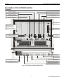
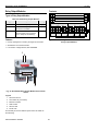
Description of the XL1000 Controller
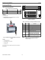
Overview
power supply LED (green)
(LED ON = power supplied)
binary output (terminals 9+10) LED (yellow)
(LED ON = application has closed contact)
binary input (terminals 3+4) LED (yellow)
(LED ON = input closed)
binary output (terminals 7+8) LED (red)
(LED ON = watchdog has closed contact)
Ethernet link LED (yellow)
(LED ON = Ethernet link is enabled)
LED2 (currently unused)
Ethernet activity LED (yellow)
(LED ON = Ethernet active)
LED1 (currently unused)
reset button
ATTENTION:
Never unscrew and
dismount the inner
metallized cover while
the XL1000 is powered!
Danger of short-circuiting!
NO CONNECTION
LonWorks service LED (yellow)
(for meaning of LED behavior, see Table 1)
L1
LON
LonWorks service button
(pushing broadcasts service pin message)
L2
1
LON
2
CF
NOT USED
NOT USED
3
7 8 9 10 1112
1 2 3 4 5 6
USB interface
NO CONNECTION
NO CONNECTION
upper terminal block (removable)
(terminals 7 thru 12)
RS232C serial interface, port 1
(standard male 9-position sub-D)
lower terminal block (removable)
(terminals 1 thru 6)
Ethernet interface (8-position,
shielded RJ45 connector jack, CAT5)
LonWorks interface (8-position,
unshielded RJ45 connector jack)
Fig. 3. Connections to the XL1000 Controller
7
EN1B-0409GE51 R0908A
Description of the XL1000 Controller
XL1000
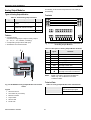
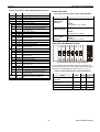
Terminal Blocks
LonWorks Interface
The XL1000 features two rows of removable terminal blocks
(located at the front left-hand side; see Fig. 3) for the connection of cables to the two binary outputs and the binary
input as well as for connecting LONWORKS and the power
supply. A nearby sticker provides an overview of the terminal
assignment (see Fig. 4).
The XL1000 is equipped with a LONWORKS interface (specifically: an RJ45 jack) for communication on LONWORKS
networks.
87654321
LON
7 8 9 10 11 12
!
LonWorks
24V
LON
~ 0
1 2 3 4 5 6
Fig. 5. LonWorks interface (RJ45 jack)
There are two methods of connecting the XL1000 to the
LONWORKS network (both or either connection method can be
used):
•
via terminals 5+6 and 11+12 of the terminal blocks (see
Fig. 3); and/or
•
via the corresponding jack located to the right of the
terminal blocks (see Fig. 5).
See also section "LonWorks Service LED and Service Button"
on page 9 for details on the corresponding LONWORKS service
LED and one LONWORKS service button.
Fig. 4. Terminal assignment sticker
Maximum torque for fastening the wiring terminal screws is
0.5 Nm (4.5 lb-in).
Table 6 provides a more-detailed explanation of the terminals
and their functions.
Table 6. Overview of terminals and functions
term.
Ethernet Interface
function
1+2
power supply (24 Vac)
3+4
a binary input (normally-open, 36 Vdc; pin 4 is the
signal ground), freely configurable (using CARE 7)
to read input from either 1) a field device or 2) a
collective alarm input or 3) a 2nd XL1000 whose
duties it could then assume in the event of its failure
5+6
LONWORKS
7+8
a binary output / "watchdog relay" (SPDT, normally
closed, 24 Vac, max. 2 A permanent load), permanently configured to output to an alarm device
(which can then signal that XL1000 is
malfunctioning)
9+10
a binary output (potential-free contact, SPST,
normally-open, 24 Vac, max. 2 A permanent load),
configurable (using CARE) to output to either 1) a
field device or 2) a 2nd XL1000 which could then
st
assume the 1 XL1000’s duties in the event of its
failure
The XL1000 is equipped with a 10/100-Mbaud Ethernet
interface (specifically: an RJ45 jack) permitting communication (as per IEEEC 802.3) on BACnet/IP networks.
87654321
Fig. 6. Ethernet interface
When thus connected, the user sitting at a platform hosting
EBI can thus e.g. view and edit the time programs, trend
values, etc. of the other devices in the BACnet/IP network.
11+12 LONWORKS
This Ethernet jack conforms to the specifications of the
following two Ethernet sub-standards:
•
100Base-TX (twisted pair / star wiring; 100 Mbaud
Ethernet based on Manchester signal encoding over
category 5 or better twisted pair cable; max. segment
length = 100 meters) and
EN1B-0409GE51 R0908A
8
XL1000
•
Description of the XL1000 Controller
10Base-T (twisted pair / star wiring; 10 Mbaud Ethernet
based on Manchester signal encoding over category 3 or
better twisted pair cable; max. segment length =
100 meters).
12.5 mm
RS232C Serial Interface Ports
The XL1000 is equipped with three male 9-pin sub-D jacks
into which corresponding female 9-pin sub-D plugs can be
inserted for various different purposes (see following subsections). These ports allow data transmission rates of 9.6,
19.2, 76.8, or 115.2 kBaud (the default).
Fig. 8. USB interface
Alternatively, either of the following two adapters can also be
used: SMC 2208USB/ETH and SMC 2209USB/ETH.
LEDs and Buttons
LonWorks Service LED and Service Button
The XL1000 is equipped with a LONWORKS service LED and a
LONWORKS service button, together marked "LON" (see Fig.
3). They are used for commissioning the XL1000 and for
troubleshooting.
Fig. 7. RS232C serial interface
The user can configure the specific desired data transmission
rate of each individual RS232C port; it is thus possible for the
three ports to operate simultaneously at three different rates.
Port 1 (Factory Service Interface)
Port 1 is intended for the connection (as needed) of a platform for the purpose of servicing (in the factory, only) the
XL1000. In this context, "servicing" comprises a group of
different activities including:
•
updating portions of the XL1000’s Operating System
(namely: LINUX, BACstack, Apache Web-Server) and
•
diagnostics (Linux, firmware).
LonWorks Service Button
When the LONWORKS service button is pressed, the service
pin message is broadcast on the LONWORKS network, and all
LONWORKS tools currently connected to the LONWORKS
network will receive this message.
LonWorks Service LED
The LONWORKS service LED can display various behaviors
having different meanings (see Table 7).
Power Supply LED
Port 2 (Browser Interface)
The LED marked " " indicates whether or not the XL1000 is
currently under power. Specifically, when it is lit, the XL1000
is under power; when it is dark, the XL1000 is not under
power.
NO CONNECTION.
Port 3 (Modem Interface)
NO CONNECTION.
Binary Input (terminals 3+4) LED
CF Port LED, Request Button, and Slot
The LED marked "
" indicates the state of the binary input
(which is a normally-open contact) located at terminals 3 and
4. Specifically, when it is lit, the binary input is closed; when it
is dark, the binary input is open.
NO CONNECTION.
USB Interface Downloads
Binary Output (terminals 7+8) LED
The XL1000 is equipped with a USB port into which a
standard USB type-A connector can be inserted. This USB
interface is the recommended interface for downloading
applications. The following USB host networking adapter has
been approved: BELKIN DIRECT CONNECT (BELKIN order
no.: F5U104 or F5U104G at www.belkin.com).
9
The LED marked " " indicates the state of the binary output
("watchdog" relay) at terminals 7 and 8 (which is a normally
closed contact). Specifically, when it is lit, the alarm contact is
open; when it is dark, the alarm contact is closed.
EN1B-0409GE51 R0908A
Mounting
XL1000
Binary Output (terminals 9+10) LED
Ethernet Link LED
The LED marked "
" indicates the state of the binary output at terminals 9 and 10 (which is a normally-open contact).
Specifically, when it is lit, this means that the application has
closed the relay; when it is dark, the relay is open.
The LED marked "
" indicates the Ethernet link's status.
Specifically, it is lit whenever an Ethernet jack has been
inserted into the corresponding port and the software has
established the Ethernet link. It is dark when the link has been
disabled.
Table 7. LONWORKS service LED behaviors / meanings
LED behavior
meaning
Ethernet Activity LED
The LED marked " ↔ " indicates whether or not the Ethernet
link is currently active. Specifically, when it flashes, this
means that signals are being transmitted / received on the
Ethernet network; when it is dark, no messages are being
transmitted/received.
1
LED remains OFF after
power-up.
Defective XL1000 hardware
(e.g. power supply problems,
clock problems, or defective
Neuron Chip).
2
LED is lit continuously after
first power-up.
Defective XL1000 hardware.
3
LED flashes at power-up,
goes OFF, and then is lit continuously.
Neuron chip lacks LONWORKS
interface program. Remedy:
Use Excelon or LonMaker, set
XL1000 online.
4
LED flashes briefly
periodically.
XL1000 probably experiencing
continuous watchdog resets,
or external memory or
EEPROM is corrupt.
Reset Button
5
LED repeatedly blinks ON for
1 s and OFF for 1 s.
XL1000 is unconfigured but
has an application. Remedy:
Commission XL1000.
The reset button can be pressed only using a long, thin tool
(e.g. a screwdriver). Pressing it reboots the XL1000’s
operating system and restarts the application.
6a
OFF for approx. 10 s. Afterwards, the service LED turns
ON and remains ON,
indicating completion of the
blanking process.
Return XL1000 to factory.
Mounting
6b
OFF for approx. 1 s. Afterwards, the service LED is lit
continuously.
Return XL1000 to factory.
6c
OFF for 1 ─ 15 s, depending
on application size and system XL1000 is unconfigured but
clock. Afterwards, service LED has an application. Remedy:
repeatedly flashes ON for 1 s Commission XL1000.
and OFF for 1 s.
7
LED remains OFF after a
short ON duration.
XL1000 is configured and
running normally.
LED flashes ON.
XL1000 received a WINK
command from LONWORKS;
other physical outputs are
unaffected.
8
LEDs L1 and L2
At present, these LED's are not in use.
Before Installation
In case of a problem, check if the LONWORKS service LED's
behavior is changed by resetting the XL1000 using the reset
button. Please contact Honeywell if this does not solve the
problem.
Ethernet LEDs
IMPORTANT
To allow the evaporation of any condensation resulting
from low shipping / storage temperatures, keep the
controller at room temperature for at least 24 h before
applying power.
In order to meet the criteria for CE certification, the XL1000
must be mounted inside an electrical panel.
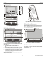
Dimensions
The XL1000 has the following dimensions (W x L x H):
278 x 190 x 61 mm. Its housing conforms to IP20. Its pollution
degree (2) makes it suitable for use in residential controls,
commercial controls, in a clean environment, or non-safety
controls for installation on or in appliances.
The XL1000 is suitable for mounting on a standard rail (DIN
EN 50022-35 x 7,5) for installation in appropriately-sized
wiring cabinets. Allow sufficient clearance (approx. 30 mm) to
access the interfaces and to open the swivel cover (see Fig.
9).
The XL1000 is equipped with two Ethernet LEDs (see Fig. 3).
EN1B-0409GE51 R0908A
10
XL1000
Mounting
Allow 30 mm clearance
for opening swivel cover.
step
1
190
LON
CF
1
LON
2
3
100 mm
0.6
278
60.6
4.4 +/- 0.3
step
2
36.5
Allow 30 mm
clearance for
accessing interfaces.
141.5 +/- 0.3
fastening
plate
step
3
step
4
Fig. 11. Mounting the XL1000 onto two DIN rails
Wall/Panel Mounting/Dismounting
12
220 +/- 0.3
5 +/- 0.3
The XL1000 can be mounted on walls or in panels in any
desired orientation. However, mounting the XL1000 upside
down on ceilings should be avoided, insofar as the swivel
cover would then swing open.
Fig. 9. Dimensions (in mm)
DIN Rail Mounting/Dismounting
slots for DIN rails
(center-to-center distance = 100 +3 mm)
5 +/- 0.3
190
17 mm
141.5 +/- 0.3
36.5
4.4 +/- 0.3
12
29
fastening
plate
220 +/- 0.3
29
278
Fig. 12. Drilling template (view from above)
Fig. 10. Housing base (view from below)
The XL1000 can be mounted onto DIN rails as follows (refer
also to Fig. 11):
1. Hang the upper slot onto the upper DIN rail.
2. Swing the unit down until it is flush with the lower DIN
rail.
3. Slide the fastening plate and corresponding screw in the
oval hole up against and behind the bottom edge of the
lower DIN rail and screw it firmly into place.
4. If necessary, the swivel cover can be locked by inserting
a small string lock, lead seal, or screw into either one of
the two openings provided.
The unit is dismounted by loosening the fastening plate and
lifting the unit out of place.
11
Swivel Cover Lock
The swivel cover can be locked by inserting a small string
lock, lead seal, or screw into either one of the two openings
provided (see Fig. 11).
EN1B-0409GE51 R0908A
Power Supply
XL1000
NOTE: Do not reverse the polarity of the power connection
cables, and avoid ground loops (i.e. avoid
connecting one field device to several controllers) as
this may result in short-circuiting.
Power Supply
Power is supplied via terminals 1 and 2 of the lower removable terminal plug. The removable terminal plug permits
individual XL1000 controllers to be disconnected from the
power supply without disturbing the operation of other devices
powered by the same source.
24 VAC CONTROLLER
POWER SWITCH
120 VAC, 60 HZ
LINE INPUT
CONTROLLER
POWER
ON
*
H
N
G
MAIN LINE VOLTAGE
120 VAC, 60 HZ
TERMINAL “G“ MUST BE
CONNECTED TO A GOOD
EARTH GROUND.
CONTROLLER
SUPPLY
24VAC
48VA
~
MUST BE WIRED
TO EARTH GROUND
“G“ MUST BE
UNSWITCHED
UNFILTERED
120 VAC
WIRED TO EARTH GROUND
BRN
GRN
BLK
CONNECTOR TO
XL1000 CONTROLLER
J5
FUSE F1 (2 AMPS) PART NUMBERS ARE AS FOLLOWS:
–HONEYWELL PART NO. 14000485-007
(AVAILABLE FROM HONEYWELL BRANCH LOCATIONS, ONLY)
–BUSSMAN PART NO. AGC-2
–LITTLEFUSE PART NO. 312002
OFF
G
14507063-002 POWER CABLE
(incl. with 14507287 power modules
14507287-001 through -003, only.)
2 AMP
F1
CONNECTORS ARE KEYED TO
PREVENT MISALIGNMENT.
CONVENIENCE OUTLET
(UNFILTERED, UNSWITCHED)
-001 = 120 VAC, 10 AMP
* 14507287-001 POWER TERMINALS LABELED H-N-G.
Fig. 13. Typical 14507287-001 Power Module wiring
24 VAC CONTROLLER
POWER SWITCH
120 VAC, 60 HZ
LINE INPUT
120 VAC, 60 HZ
LINE INPUT
CONTROLLER
POWER
ON
*
H
N
G
MAIN LINE VOLTAGE
120 VAC, 60 HZ
TERMINAL “G“ MUST BE
CONNECTED TO A GOOD
EARTH GROUND.
OFF
24VAC ACCESSORY
POWER -002 AND -003
MODELS (4 AMP MAX.)
5 AMP
F2
2 AMP
F1
ON
OFF
CONTROLLER
SUPPLY
MUST BE WIRED
TO EARTH GROUND
24VAC
48VA
~
2 AMP
F3
~
G
14507063-002 POWER CABLE
(incl. with 14507287 power modules
14507287-001 through -003, only.)
“G“ MUST BE
WIRED TO EARTH GROUND
24 VAC ACCESSORY POWER
-002 MODEL, ONLY. 2 AMP MAX.
FOR 14507287-003 (24VDC) BRN GRY BRN GRY
FOR 14507287-002 (24VAC) RED BRN GRY GRY
BRN
GRN
BLK
CONNECTOR TO
XL1000 CONTROLLER
J5
UNSWITCHED
UNFILTERED 120 VAC
CONNECTORS ARE KEYED TO
PREVENT MISALIGNMENT.
CONVENIENCE OUTLET
(UNFILTERED, UNSWITCHED)
-002 AND -003 = 10 AMP
* 14507287-001 POWER TERMINALS LABELED H-N-G.
POWER MODULE
14507287-001 THROUGH -003
14507287-002 AND -003
14507287-002 AND -003
FUSE NO.
FUSE RATING
HONEYWELL PART NO.
BUSSMAN PART NO.
LITTLEFUSE PART NO.
F1
F2
F3
2 AMPS
5 AMPS
2 AMPS
14000485-007
14507374-001
14000485-007
AGC-2
GMA 5AMP
AGC-2
312002
235005
312002
Fig. 14. Typical 14507287-002, -003 Power Module wiring
EN1B-0409GE51 R0908A
12
XL1000
Power Supply
CONTROLLER TRANSFORMER
CONTROLLER
SUPPLY 24 VAC
48 VA
G 70
BRN
~ 71
BLK
72
H
BLK
N
WHT
G
GRN
3
4
1
24 V 50 VA
14507351-001
429P156A
E1A 1052 XXXX
COM
1
MAIN LINE (120 VAC, 60 Hz)
TERMINAL “G” MUST BE
CONNECTED TO A GOOD
EARTH GROUND.
1
GRN
120 V
2
1
MECHANICALLY SECURED TO SUBPANEL WITH MOUNTING SCREW
Fig. 15. Typical 14507287-007 Power Module wiring
13
EN1B-0409GE51 R0908A
LonWorks Communications
Lightning Protection
LONWORKS:
14502412-014
Ethernet:
14507678-004
Interfaces and Bus Connections
XL1000
LonWorks Communications
General Information
The XL1000 is equipped with a free-topology transceiver
(FTT10A or FT-X1) for communication (at a data transmission
rate of 78 Kbaud) on LONWORKS® networks (using the
LonTalk protocol).
The XL1000 System can be connected to the following
devices and systems:
The LONWORKS network is insensitive to polarity, eliminating
the possibility of installation errors due to miswiring.
LonWorks Bus
Different network configurations (daisy-chain, loop, and star
configurations, or any combination thereof) are possible (see
also Excel 50/500 LONWORKS Mechanisms Interface
Description, EN0B-0270GE51).
• For communication with other LONWORKS Bus devices
within the building
• FTT10, link power compatible
• Polarity-insensitive
Technical Data
System Data
Table 8. System data
operating voltage
24 VAC/DC, 60 Hz
power
consumption
max. 7 A
(one XL1000 + 40 I/O modules)
Connecting to the LONWORKS Network
IMPORTANT
Do not bundle wires carrying field device signals or
LONWORKS communications together with high-voltage
power supply or relay cables. Specifically, maintain a
min. separation of 3 inches (76 mm) between such
cables. Local wiring codes may take precedence over
this recommendation.
IMPORTANT
Try to avoid installing in areas of high electromagnetic
noise (EMI).
XL1000
NOTE:
The max. permitted number of LonWorks I/O
modules depends upon the type of modules used.
In the case, e.g., of XL800 Binary Input Modules, a
maximum of 21 may be used.
11 12
5 6
ambient operating
humidity
5 ─ 93 % relative humidity
(non-condensing)
ambient storage
temperature
–20 ─ 70 °C (–4 ─ +158 °F)
ambient storage
humidity
5 ─ 95 % relative humidity
(non-condensing)
5 6
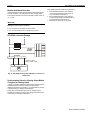
Fig. 16. Connection to LONWORKS network and
termination module (here: daisy-chain network
configuration)
Table 9. Operational environment
0 ─ 49 °C (32 ─ 122 °F)
11 12
termination
module
Operational Environment
ambient operating
temperature
XL1000
The XL1000 can be connected to the LONWORKS network via
terminals 5+6 and 11+12 of the removable terminal plug or
via the LONWORKS jack (see also section "LonWorks
Interface" on page 8).
This permits individual XL1000 controllers to be connected /
disconnected from the LONWORKS network without disturbing
the operation of other devices.
Depending upon the chosen network configuration, one or
two terminations may be required.
Two different LONWORKS termination modules are available:
• LONWORKS termination module, order no.:
209541B
• LONWORKS connection / termination module
(mountable on DIN rails and in fuse boxes),
order no.:
XAL-Term
EN1B-0409GE51 R0908A
14
XL1000
Binary Input and Outputs
The binary input is protected against miswiring. Specifically, it
is protected against voltages of up to 29 Vac; when miswired,
the XL1000 is unable to detect a valid input signal.
Honeywell
XAL-Term
3
4
3
5
shield
6
The XL1000 is equipped with two binary outputs.
LON
Termination
plug-in
jumper
removable screw-type
3-pole terminal block
Binary Outputs
4
1
shield
0
FTT/LPT Bus
FTT/LPT Free
Park Position
L
O
N
L
O
N
Hardware Limits
•
A min. current of 50 mA is required to ensure a reliable
contact.
The binary outputs are designed for a max. continuous
current of 2 A.
Switching voltage = 24 Vac, 60 Hz
•
•
Fig. 17. LONWORKS connection and termination module
Binary Input and Outputs
Wiring
When wiring the two binary outputs and the binary input, use
2
a min. size of 20 AWG (0.5 mm ) and a maximum of 14 AWG
2
(2.5 mm ). The max. length of all cables is 400 m.
Binary Input
The XL1000's binary input (a normally-open contact) is not
electrically isolated. It is suitable for connection with /
signalling via 24 Vdc voltage or external resistor or dry
contact.
Protocolling
In the context of the XL1000, "protocolling" means creating a
log of the values or states of the data-points which have
been assigned to this particular XL1000. Using the
browser interface, the user must place the corresponding
data-points into "trend." If, at some later point in time, i.e. after
lengthy operation, a protocol of the XL1000's history is
desired, the corresponding trend data can be generated,
viewed, and downloaded (in CSV format) via the browser
interface. For the storage of larger amounts of trend data
(more than 64,000 trend entries – corresponding to approx.
2 MB), a CF card (see section "CF Port LED, Request Button,
and Slot") can be used.
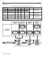
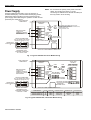
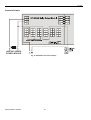
XL1000 Configuration
1
14507287-001,
-002, -003, -007
POWER SUPPLY
XL1000C500U
(XL WEB)
LON
120 VAC
60 Hz
2
ANALOG INPUT
ANALOG OUTPUT
ANALOG OUTPUT
DIGITAL INPUT
DIGITAL OUTPUT
DIGITAL OUTPUT
14502412-014
LIGHTNING
PROTECTOR
14506944-01
TOTAL EQUALIZER
PROTECTOR
14506944-01
TOTAL EQUALIZER
PROTECTOR
14506944-01
TOTAL EQUALIZER
PROTECTOR
14506944-01
TOTAL EQUALIZER
PROTECTOR
14506944-01
TOTAL EQUALIZER
PROTECTOR
14506944-01
TOTAL EQUALIZER
PROTECTOR
14502412-014
LIGHTNING
PROTECTOR
XFL821AU
XFL822AU
XFLR822AU
XFL823AU
XFL824AU
XFLR824AU
3
ETHERNET
4
6
5
14507678-004
DITEK SURGE
SUPPRESSOR
14507678-004
DITEK SURGE
SUPPRESSOR
14507719-001
BLACK BOX HUB
14507678-004
DITEK SURGE
SUPPRESSOR
14507678-004
DITEK SURGE
SUPPRESSOR
EBI
(R310)
120 VAC
60 Hz
120 VAC
60 Hz
Fig. 18. XL1000 configuration
15
EN1B-0409GE51 R0908A
XL1000 Configuration
1
2
XL1000
3
Locate per UL555S.
4
Locate separate from and below all building exhaust
fans and upstream of any prevailing winds.
5
Exhaust to outside of building.
6
Locate airflow differential switch.
7
Locate UL-listed damper pressure / position indicator
per damper installation instructions.
8
Smoke control must be initiated by a listed fire alarm
control unit or in zone automatic alarm devices and not
devices located outside of the smoke control zone.
Interconnecting wiring must be within 20 ft. (6 meters)
and in conduit.
9
Refer to NFPA 92A.
10
Verify that the AC voltage source connected to the
inside of the main line voltage terminal block is from a
UL-1481 listed uninterruptible power supply. The main
line voltage terminal block maximum current draw is
0.5 A. For 220/240 VAC (60 Hz) applications, verify
that no potential between any conductor and the earth
ground exceeds 150 VAC.
11
All external LONWORKS bus field wiring must be limited
to 4000 ft. (1200 meters) and be terminated to
14506944-001 transient protector (35 V, 290 mA
max.).
Power supply output power
24 VAC, 60 Hz, 48 VA (-001, -002, -003, and -007)
24 VAC, 60 Hz, 100 VA (-002 and -003, only)
24 VAC, 60 Hz, 40 VA (-002, only)
24 VDC, 60 Hz, 0.6 A (-003, only)
LONWORKS wire distance
1200 m (approx. 4000 ft.)
24 ohm total line resistance
47 microfarad capacitance
3
XFL822AU / XFLR822AU
8 analog outputs
10 V, 1 mA each
4
XFL824AU / XFLR824AU
6 digital outputs
4 A max. per output (relay current)
12 A max. per module
5
W7761A2010/U
W7751D2016/U
W7751F2011/U
W7751B2010
W7751H2025
separately listed S4804, Vol. 3
6
Ethernet line load
pin 1 – 10 ohm
pin 2 – 10 ohm
pin 3 – 10 ohm
pin 6 – 10 ohm
Data File Set-Up
Smoke Control Configuration
SMOKE CONTROL CONFIGURATION
XL1000
AO
UL-LISTED
FIRE ALARM
CONTROL UNIT
SUPPLY
FAN
AO
2
4
AIRFLOW SENSOR
11
8
FIREFIGHTERS’
SMOKE CONTROL
PANEL (FSCS)
14505068
AUDIBLE
ANNUNCIATOR
9
EXHAUST
FAN
AO
5
DAMPER
3
VERIFICATION
1
STATUS CONTROL
10
6
Also required for a dedicated application for the XL1000, is a
weekly time program to test control points, fans, and dampers
by exercising the equipment and verifying feedback
automatically during low building activity periods.
7
Fig. 19. Typical smoke control configuration
NOTES:
1
Locate and configure per NFPA 92A, Section 3-4.3.4.
UL-listed annunciator / FSCS panel switches have a
minimum rating of 24V, 1/10 Amp, and lamps / LEDs
have a rating of 24 V, limited to 50 mA.
2
Locate so as to minimize control wiring and piping.
Avoid running wires or piping through areas that have
a high fire risk.
EN1B-0409GE51 R0908A
Generate the engineering data file for the XL1000 Series
Controllers. This data file has a mix of hardware points for the
necessary inputs and outputs to control fans, dampers, and
other equipment. In addition to the inputs and outputs, a
custom control program is written to control the outputs per
the sequence. The XL1000 controllers can reset the program
once the data from the operator interface indicates a normal
condition for the dedicated smoke control equipment. Wire
conditions must be programmed to provide annunciation of
trouble conditions.
Panel Reset
When in Smoke Control Mode, panel reset is accomplished
by resetting the initiating panel contact circuit or by the
separate initiating/reset switch on the FSCS panel.
16
XL1000
XL1000 Configuration
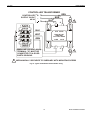
CAUTION
Connecting Single Bus Controller Systems
Risk of electric equipment damage!
This section describes how to connect a controller system
which uses LONWORKS I/O modules, only.
► Failure to use listed/approved replacement parts can
damage product, degrade operation and result in loss of
safety function.
► This product must be installed and operated within its
environmental, mechanical, and electrical specifications as
contained in this document.
► When servicing, use only listed/approved replacement
parts ordered directly from the manufacturer.
2
► Connect the rail ends as follows:
NON-POWER
LIMITED
ANALOG INPUT
MODULE
ANALOG OUTPUT
MODULE
DIGITAL INPUT
MODULE
DIGITAL OUTPUT
MODULE
ACCESSORY
24VAC
2
1
NON-POWER
LIMITED
71
72 LonWorks
73 I/O MODULE
74
2
3
1
NON-POWER
LIMITED
NON-POWER
LIMITED
71
72 LonWorks
73 I/O MODULE
74
Fig. 20. Typical power-limited circuit for XL1000
1
– Power supply
via power supply terminals 73, 74 or 77, 78
– Communication
via communication terminals 71, 72 or 75, 76
POWER LIMITED
24VAC
CONTROL
24VAC
connectors.
This provides power supply and communication connection.
No further wiring is necessary.
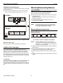
The multiple rails of a controller system are connected in
series.
POWER
LIMITED
CPU
► Connect XL1000 and I/O modules using the bridge
XL1000, I/O Modules on Rails in Single Cabinet
Typical Power Limited Circuit for XL1000
POWER
LIMITED
XL1000, I/O Modules on Single Rail
14507287-001 through -003 power module accessory
24 VAC output (rated 2A) must be wired in accordance
with NFPA 70, Article 725 when routed within the
cabinet or adjacent cabinets and also for external field
wiring.
2
14507287-001, -002, -003, and -007 control power
module 24 VAC output is inherently power-limited.
Thus, all sourced power from the XL1000 controller is
power-limited. All field wiring from these controllers
meet NFPA 70, Article 725 power limited Class II
requirements.
3
If a separate auxiliary power-limited 24 VAC power
source is required, use a control power module
(14507287-001 or -007 control supply).
4
Devices must be installed in areas as shown. All cable
must be routed as shown. All internal power-limited
wiring must be separated by ¼ inch (6 mm) or barrier
from non-power-limited wire. Excess wiring must be
cut, trimmed, and dressed properly to ensure that
proper clearances are maintained.
17
75
71
72 LonWorks 76
73 I/O MODULE
74
LonWorks
I/O MODULE
5
6
11
XL1000 12
12
LonWorks
I/O MODULE
75
76
77
78
75
71
72 LonWorks 76
I/O MODULE 77
78
71
72 LonWorks
73 I/O MODULE
74
Fig. 21. Wiring power supply and communication lines to
the I/O modules
EN1B-0409GE51 R0908A
Mounting/Dismounting Modules
XL1000
I/O Modules in Separate Rooms
In this scenario, only communication lines must be connected
between the rooms.
Mounting/Dismounting Modules
WARNING
► Connect the last module of room 1 to the first module of
room 2: via communication terminals 71, 72 or 75, 76
Risk of electric shock or equipment damage!
► Do not touch any live parts in the cabinet.
► Disconnect the power supply before you start to install the
ROOM 1
75
71
72 LonWorks 76
I/O
MODULE
73
77
78
74
5
6
11
XL1000 12
12
75
71
72 LonWorks 76
I/O
MODULE
73
74
controller system.
More than one disconnect switch may be required to deenergize the system.
► Do not reconnect the power supply until you have
completed the installation.
NOTE:
ROOM 2
LonWorks
73 I/O MODULE
74
The terminal socket of each I/O module can be
mounted and wired before inserting and locking
the corresponding electronic module.
Mounting/Dismounting Sockets
LonWorks
I/O MODULE
75
LonWorks 76
I/O MODULE 77
Mounting Sockets
78
LonWorks LonWorks
I/O Module I/O Module
XL1000
LonWorks
LonWorks LonWorks
I/O Module I/OBUS
Module
I/O
max. no.: approx. 40
(depending upon mix)
Fig. 22. Wiring LONWORKS I/O modules in separate rooms
Fig. 23. Max. number of LONWORKS I/O modules
NOTE:
Maximum Cable Length
Max. cable length: 1200 meters (4000 ft), supervised.
LONWORKS Bus Topologies
The max. permitted number of LonWorks I/O
modules depends upon the type of modules used.
In the case, e.g., of XL800 Binary Input Modules, a
maximum of 21 may be used.
► Angle the terminal socket at the upper edge of the DIN rail
until it snaps in.
► Swing the terminal socket down and apply gentle force
The LONWORKS Bus is a 78-kilobit serial link that uses
transformer isolation so that the bus wiring does not have a
polarity. I.e. it is not important which of the two LONWORKS
Bus terminals are connected to each wire of the twisted pair.
The LONWORKS Bus can be wired in daisy chain, star, loop or
any combination thereof as long as the maximum wire length
requirements are met.
until it snaps into position with an audible "click".
► Position terminal sockets flush with one another along the
rail.
► If desired, mount stoppers at the ends of the rail to prevent
sliding.
Configuration
The recommended configuration is a daisy chain with two bus
terminations. This layout allows for max. LONWORKS Bus
lengths, and its simple structure presents the least number of
possible problems, particularly when adding on to an existing
bus.
EN1B-0409GE51 R0908A
18
XL1000
Mounting/Dismounting Modules
Fig. 25. Connecting terminal sockets with bridge
connector
NOTE:
Fig. 24. Mounting terminal sockets
Connecting Sockets
Terminal sockets on the same DIN rail can be connected
mechanically and electrically with bridge connectors.
Bridge connectors transmit both communication
signals and power supply between I/O modules.
Removing bridge connectors will interrupt the
transmission of both communication signals and
power supply between the I/O modules.
Dismounting Terminal Sockets
Disconnecting Terminal Sockets
The XL1000 and terminal sockets must be connected using
cables.
Release all bridge connectors before removing the terminal
sockets from the DIN rail.
NOTICE
► Press down at the same time both the gray side wings next
to the red button and then pull the bridge connector out of
the terminal socket.
Risk of malfunction!
► LONWORKS I/O modules must be connected to the XL1000
via LON terminals 5 and 6 and/or 11 and 12.
Position the bridge connector on terminals 71 ─ 74 of the
right-hand terminal socket and on terminals 75 ─ 78 of the
left-hand terminal socket. Then press the bridge connector
down.
Fig. 26. Releasing bridge connectors
Dismounting Terminal Sockets
► Insert a screwdriver into the latch on the underside of the
terminal socket and lever the red latch 2–3 mm downwards. The terminal socket can then be swung away from
the rail.
19
EN1B-0409GE51 R0908A
Mounting/Dismounting Modules
XL1000
Fig. 29. Locking the electronic module
Fig. 27. Releasing latch
Mounting/Dismounting Electronic Modules
Mounting Electronic Modules
NOTE:
Electronic modules can be removed from the
terminal socket or inserted into the terminal
sockets without switching off the power supply.
The behavior of connected field devices must be
taken into consideration.
► Make sure that terminal socket und I/O module match.
► Make sure that the red locking mechanism is in the open,
NOTE:
The red locking mechanism will not close if the
electronic module is not properly mounted.
Dismounting Electronic Modules
NOTE:
Electronic modules can be removed from the
terminal socket or inserted into the terminal
sockets without switching off the power supply.
The behavior of connected field devices must be
taken into consideration.
► Open the red locking mechanism by sliding it to the left
and then gently pull the electronic module out of the
terminal socket.
i.e., left-hand, position.
► Gently push the electronic module onto the terminal socket
until snug.
Fig. 30. Dismounting the electronic module
Connecting HMIs or Laptops
Fig. 28. Inserting the electronic module
► Lock the red locking mechanism by sliding it to the right.
Laptops or HMIs (e.g., XI882) can be connected via the
XL1000’s Ethernet interface (see section “Ethernet Interface”
on page 8) or its USB interface (see section “USB Interface
Downloads” on page 9).
Connecting Laptops (XW-Online/CARE)
► Connect a laptop (on which e.g., XW-Online or CARE has
been installed) to the XL1000’s Ethernet interface (see
section “Ethernet Interface” on page 8) or its USB interface
(see section “USB Interface Downloads” on page 9).
EN1B-0409GE51 R0908A
20
XL1000
Description of the I/O Modules
Description of the I/O Modules
Common Features
Switches Located on the Terminal Socket
Table 10. Terminal socket switches
feature
function
Service button • LED test, see section "Troubleshooting"
S1
on page 31
• LONWORKS service button functionality
for LONWORKS I/O modules
Hex switch S2 • No function.
LEDs Located on the I/O Module
Table 11. LEDs on I/O module
feature
function
Service LED
(yellow)
• Service information, see section
"Troubleshooting" on page 31
Power LED
(green)
• Information on power supply, see
section "Troubleshooting" on page 31
For the location of these elements, see figures of the
respective modules.
21
EN1B-0409GE51 R0908A
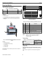
Description of the I/O Modules
XL1000
Terminals
Analog Input Modules
71 COM
A
Types of Analog Input Modules
72
Table 12. XL800 Analog Input Modules
type
description
73
74
housing
XFL821
LONWORKS Analog Input Module
dark-gray
XS821-822
terminal socket
light-gray
COM
A
COM
B
24
V~
24
V~0
COM
B
24
V~
24
V~0
VAUX VAUX
1
2
3
4
5
6
7
77
78
8
GND GND
GND GND GND GND GND GND GND GND
9 10
11 12 13 14 15 16 17 18
• 8 analog inputs
76
AI1 AI2 AI3 AI4 AI5 AI6 AI7 AI8
21 22
Features
75
25 26
• Sensor-break and short-circuit detection, see section
"Troubleshooting" on page 31.
1
Fig. 32. Terminal assignment and internal connections of
Analog Input Modules
2
Table 13. Description of Analog Input Module terminals
3
4
Fig. 31. XFL821AU Analog Input Module with terminal
socket
Hex switch S2 (no function)
3
Service LED
4
Power LED
Functionality of service LED and power LED: see Table 24
and following.
EN1B-0409GE51 R0908A
comment
71, 75
COM a
2-wire LONWORKS communication bus
72, 76
COM b
2-wire LONWORKS communication bus
73, 77
24 V~
Power supply
74, 78
24 V~0
1─8
AI1 ─ AI8
9 ─ 18
GND
21, 22
10 VDC /
5 mA
NOTE:
Service button S1
2
signal
25, 26
Legend
1
terminal
22
Power supply
Analog inputs 1 ─ 8
Ground. All grounds are connected
internally to each other
Auxiliary voltage signal (used e.g. for
supplying setpoint potentiometers).
Connections to these terminals
must be made in the same room.
Shield connection (functional earth),
internally connected to the DIN rail
Shield connection to be used for shielded I/O
cables only. It is not allowed to connect a
LONWORKS shield.
XL1000
Description of the I/O Modules
XFL821AU Connection Examples
400 OHM
1
18
1
2
25
2
12
1
2
SHIELD
25
SHIELD
0(4) to 20 mA
0 to 10 V
0(4) to 20 mA (VIA EXTERNAL
500 OHM RESISTOR).
0 TO 10 VDC
5
14
22
10
11
12
25
3
13
1
2
SHIELD
VMP
25
SHIELD
Pt1000 NTC20kW
Fig. 33. XFL821AU Analog Input Module, connection to
field devices
23
EN1B-0409GE51 R0908A
Description of the I/O Modules
XL1000
Analog Output Modules
Functionality of service LED and power LED: see Table 24
and following.
Types of Analog Output Modules
Table 14. XL800 Analog Output modules
type
description
Terminals
housing
XFL822
LONWORKS Analog Output
Module
dark-gray
XFLR822
LONWORKS Analog Output
Module with manual overrides
dark-gray
XS821-22
terminal socket
light-gray
Features
• 8 analog outputs;
can also be configured per output as binary outputs
(0 ─ 10 V, 2 ─ 10 V, ON/OFF, or floating)
• Corresponding output status LEDs (red)
Fig. 35. Terminal assignment and internal connections of
the Analog Output Modules
• XFLR822AU: 8 manual overrides
Table 15. Description of Analog Output Module terminals
1
2
terminal
signal
comment
71, 75
COM a
2-wire LONWORKS communication bus
72, 76
COM b
2-wire LONWORKS communication bus
73, 77
24 V~
Power supply
74, 78
24 V~0
Power supply
1─8
AO1 ─ AO8 Analog outputs 1 ─ 8
9 ─ 18
GND
Ground. All grounds are connected
internally to each other
21, 22
N.C.
Do not use!
3
Shield connection (functional earth),
internally connected to the DIN rail
25, 26
NOTE:
4
5
6
Shield connection to be used for shielded I/O
cables only. It is not allowed to connect a
LONWORKS shield.
Technical Data
Fig. 34. XFLR822AU Analog Output Module with terminal
socket
Legend
1
Service button S1
2
Hex switch S2 (no function)
3
Manual overrides
4
Output LEDs
5
Service LED
6
Power LED
EN1B-0409GE51 R0908A
Table 16. Analog Output Module status LED behavior
automatic mode
brightness follows the
commanded output signal
override mode
flashes
24
XL1000
Description of the I/O Modules
Modules with Manual Overrides
The XFLR822AU Analog Output Modules are equipped with
manual overrides: one rotary knob for each analog output.
The manual overrides can be set manually to either "auto" or
"0 ─ 110%".
NOTICE
This updating (synchronization) is performed:
• If the calculated position of the actuator
< lower synchronization threshold (2 %)
= synchronization towards 0 %
• If the calculated position of the actuator
> upper synchronization threshold (98 %)
= synchronization towards 100 %
• Following any power-up or any reset
Damage to the electronic module!
► Do not use a tool to adjust the rotary knobs.
► Do not use excessive force. Adjust only by hand.
XFL822AU Connection Example
L
N
24V
14507287
POWER
MODULE
~
XFL822AU
8
11
1
73
XSL511
Umax = 11 VDC
Imax = 1 mA, -1 mA
GND SIGNAL 24VAC
M
Fig. 36. XFL822AU Analog Output Module, connection to
field devices
Synchronization Behavior of Analog Output Module
Configured as Floating Output
In order to regularly update the real actuator position with the
calculated position and thus ensure that the actuator
definitely reaches its end position, a synchronization process
is performed by the Analog Output Module.
During the synchronization process, the Analog Output
Module will continue running for the configured runtime once
it reaches the calculated end position.
25
EN1B-0409GE51 R0908A
Description of the I/O Modules
XL1000
Terminals
Binary Input Modules
71 COM
A
Types of Binary Input Modules
72
Table 17. XL800 Binary Input Modules
type
description
73
74
housing
XFL823
LONWORKS Binary Input Module
dark-gray
XS823
terminal socket
light-gray
COM
A
COM
B
24
V~
24
V~0
COM
B
24
V~
24
V~0
75
76
77
78
BI1 BI2 BI3 BI4 BI5 BI6 BI7 BI8 BI9 BI10 BI11 BI12
1
Features
2
3
4
5
6
7
8
9
10 11 12
GND GND GND GND GND GND GND GND GND GND GND GND
13 14 15 16 17 18 19 20 21 22 23 24
• 12 binary inputs
25 26
• 12 configurable status LEDs (green/red, yellow/OFF)
• Binary inputs can be used as static digital inputs (drycontacts)
1
Fig. 38. Terminal assignment and internal connections of
Binary Input Modules
Table 18. Description of Binary Input Module terminals
2
terminal
signal
comment
71, 75
COM a
2-wire LONWORKS communication bus
72, 76
COM b
2-wire LONWORKS communication bus
73, 77
24 V~
Power supply
74, 78
24 V~0
Power supply
1 ─ 12 BI1 ─ BI12 Binary inputs 1 ─ 12
13 ─
24
3
GND
Shield connection (functional earth),
internally connected to the DIN rail.
25, 26
NOTE:
4
5
Ground. All grounds are connected
internally to each other.
Shield connection to be used for shielded I/O
cables only. It is not allowed to connect a
LONWORKS shield.
Technical Data
Fig. 37. XFL823AU Binary Input Module with terminal
socket
Legend
Table 19. Technical data for of Binary Input Modules
input type
dry-contact
current rating (closed input)
2 mA
open contact voltage
16 ─ 22 VDC
1
Service button S1
2
Hex switch S2 (no function)
3
Input LEDs
4
Service LED
Status LEDs
5
Power LED
The status LEDs can be configured individually for use as
either alarm LEDs (red/green) or as status LEDs (yellow/OFF
[default]).
Functionality of service LED and power LED: see Table 24
and following.
EN1B-0409GE51 R0908A
Given a state of "logical ON," the LED will be lit (yellow or
red).
26
XL1000
Description of the I/O Modules
XFL823AU Connection Examples
1
13
1
2
25
2
14
SHIELD
5 TO 24V
2
MIN.
25 MS
3
1
MIN.
25 MS
15
1
CONTACT SUITABLE FOR
LOW VOLTAGE (GOLD).
2
PROTECTED SWITCHING
UP TO 40 VDC / 24 VAC.
5 TO 24
VDC
1
~ 120V
PT1000 NTC20kW
Fig. 39. XFL823AU Binary Input Module, connection to
field devices
27
EN1B-0409GE51 R0908A
Description of the I/O Modules
XL1000
Terminals
Relay Output Modules
71 COM
A
Types of Relay Output Modules
73
Table 20. XL800 Relay Output Modules
type
COM
A
COM
B
24
V~
24
V~0
72 COM
B
description
74
24
V~
24
V~0
75
76
77
78
housing
XFL824
LONWORKS Relay Output Module dark-gray
XFLR824
LONWORKS Relay Output Module dark-gray
with manual overrides
XS824-25
terminal socket; can be fitted
with long (red) cross connector
(incl. in scope of the delivery)
Relay block 1
light-gray
Relay block 2
NO
11
NO 21
NO
31
NO
41
NO
51
NO
61
NC
12
NC 22
NC
32
NC
42
NC
52
NC
62
COM
13
COM 23
COM
33
COM
43
COM
53
COM
63
CON
14
CON 24
CON
34
CON
44
CON
54
CON
64
25
Cross connector (can be removed, as desired)
Features
• 6 relays (changeover contacts), arranged in two blocks
Fig. 41. Terminal assignment and internal connections of
Relay Output Modules
• XFLR824AU: 6 manual overrides
• Low and line voltage allowed, see WARNING.
1
2
3
4
5
6
Fig. 40. XFLR824AU Relay Output Module with terminal
socket
Legend
1
Service button S1
2
Hex switch S2 (no function)
3
Manual overrides
4
Status LEDs
5
Service LED
6
Power LED
Functionality of service LED and power LED: see Table 24
and following.
EN1B-0409GE51 R0908A
28
XL1000
Description of the I/O Modules
Table 21. Description of Relay Output Module terminals
terminal
comment
Table 22. Permissible loads of Relay Output Modules
2-wire LONWORKS communication bus
COM b
2-wire LONWORKS communication bus
24 V~
Power supply
24 V~0
Power supply
REL1 N.O. Relay 1 N.O. contact
REL1 N.C. Relay 1 N.C. contact
R1 COM
relay 1 common contact
For connection of relay 1 common via
R1 COM
14
cross connector*
REL2 N.O. Relay 2 N.O. contact
21
REL2 N.C. Relay 2 N.C. contact
22
R2 COM
23
Relay 2 common contact
For connection of relay 2 common via
R2 COM
24
cross connector*
REL3 N.O. Relay 3 N.O. contact
31
REL3 N.C. Relay 3 N.C. contact
32
R3 COM
33
Relay 3 common contact
For connection of relay 3 common via
R3 COM
34
cross connector*
REL4 N.O. Relay 4 N.O. contact
41
REL4 N.C. Relay 4 N.C. contact
42
R4 COM
43
Relay 4 common contact
For connection of relay 4 common via
R4 COM
44
cross connector*
REL5 N.O. Relay 5 N.O. contact
51
REL5 N.C. Relay 5 N.C. contact
52
R5 COM
53
Relay 5 common contact
For connection of relay 5 common via
R5
COM
54
cross connector*
REL6 N.O. Relay 6 N.O. contact
61
REL6 N.C. Relay 6 N.C. contact
62
R6 COM
63
Relay 6 common contact
For connection of relay 6 common via
R6 COM
64
cross connector*
Shield connection (functional earth),
25
internally connected to the DIN rail
* Do not connect by wire!
COM a
max. load
RELAY BLOCK 1
71, 75
72, 76
73, 77
74, 78
11
12
13
signal
Permissible Loads
per relay output
module (total)
(common)
24 VAC, 60 Hz
12 A
24 VDC
12 A resistive, 12 A, 0.6 PF
per normally open
contact (common)
24 VAC, 60 Hz
4A
24 VDC
4 A resistive, 4 A, 0.6 PF
per normally
closed contact
(common)
24 VAC, 2 A, 60 Hz
24 VDC
4 A resistive, 4 A, 0.6 PF
Status LEDs with Manual Overrides
5
6
1
2
4
3
Honeywell
RELAY BLOCK 2
--1
--0
--AUTO
!
Fig. 42. Manual overrides (toggle switches)
The XFLR824AU Relay Output Modules are equipped with
six manual overrides: one for each relay output. These toggle
switches can manually be set to either "auto" or "0" or "1".
Table 23. Relay Output Module status LED behavior
mode
LED
N.O.*
N.C.*
(direct) (reverse)
automatic mode, state
“logical ON”
ON
ON
OFF
automatic mode, state
“logical OFF”
OFF
OFF
ON
override mode (setting “0”)
flashes
OFF
ON
override mode (setting “1”)
flashes
ON
OFF
*As configured during engineering.
29
EN1B-0409GE51 R0908A
XL1000
Connection Example
71 COM
A
72
73
74
COM
A
COM
B
24
V~
24
V~0
COM
B
24
V~
24
V~0
NO
11
NO 21
NO
31
NO
41
NO
51
NO
61
NC
12
NC 22
NC
32
NC
42
NC
52
NC
62
COM
13
COM 23
COM
33
COM
43
COM
53
COM
63
CON
14
CON 24
CON
34
CON
44
CON
54
CON
64
75
71 COM
A
76
72 COM
B
77
73
78
74
24
V~
24
V~0
25
1 2
M
14507287 SERIES
POWER MODULE
Fig. 43. XFL824AU connection example
EN1B-0409GE51 R0908A
30
XL1000
Troubleshooting
Troubleshooting
Testing Wiring Connections
The push-in terminals feature small holes (1 mm in diameter)
which can be used to measure the signals.
► Insert a probe (1) as shown in Fig. 44.
Fig. 44. Testing wiring connections
I/O Modules Troubleshooting
► Check if the power supply voltage level is OK and that
there is no high voltage (> 24 VAC or > 40 VDC)
connected to the inputs/outputs of the XFL821AU,
XFL822AU, XFLR822AU, and XFL823AU I/O modules.
► Replace the problem LONWORKS I/O module with another
module of the same kind.
– If the problem persists, this is an indication that the
problem is caused by the application or incorrect wiring.
– If the problem is solved, this is an indication that the
LONWORKS I/O module was defective.
For troubleshooting purposes on all LONWORKS I/O modules,
the following features can be used:
•
Power LED
•
Service LED
•
Service button
In addition, a module-specific troubleshooting may be
necessary.
31
EN1B-0409GE51 R0908A
XL1000
Power LED of I/O Modules
Table 24. Power LED of LonWorks I/O modules
case
power LED
meaning
remedy
1
ON
LONWORKS I/O module is powered
No action necessary
2
OFF
No power
► Check power supply
3
flashing continuously
If the LONWORKS I/O module’s service LED is ► Wait until rebooting (firmware
likewise flashing, the LONWORKS I/O module is
download) has been completed
in the boot mode
Service LED of I/O Modules
Table 25. Service LED of LonWorks I/O modules
case
Service LED
meaning
remedy
1
LED remains OFF after
power-up
If the power LED is also OFF, then
– Defective device hardware
– Possible power supply problems, clock
problems, defective processor
► Replace hardware
2
LED is lit continuously after
first power-up
Defective hardware
► Replace hardware
3
LED flashes at power up,
goes OFF, and then is lit
continuously
LONWORKS I/O module lacks application
► Download application
4
LED repeatedly blinks
ON for 1 sec and
OFF for 1 sec
LONWORKS I/O module is unconfigured, but has ► Set module to configured mode
an application
5
LED remains OFF after a
short ON duration
LONWORKS I/O module is configured and
running normally
No action necessary
6
LED flashes continuously in
following pattern:
4 x ON/OFF followed by
pause
Sensor failure of Analog Input Module
(this behavior can occur only if the appropriate
NV has been bound)
► Check sensor or connection
► Check sensor configuration
7
LED flashes continuously in
following pattern:
5 x ON/OFF followed by
pause
LONWORKS I/O Module has received the wink
command from network, physical outputs are
unaffected
No action necessary
8
LED flashes continuously in
following pattern:
6 x ON/OFF followed by
pause
Boot loader problem or hardware defect
► Replace hardware
9
LED flashes continuously in
following pattern:
7 x ON/OFF followed by
pause
Communications failure
► Check bus wiring
► Check heartbeat
Manufactured for and on behalf of the Environmental and Combustion Controls Division of Honeywell Technologies Sàrl, Ecublens, Route du Bois 37, Switzerland by its Authorized Representative:
Automation and Control Solutions
Honeywell GmbH
Böblinger Strasse 17
71101 Schönaich / Germany
Phone: (49) 7031 63701
Fax:
(49) 7031 637493
http://ecc.emea.honeywell.com
Subject to change without notice. Printed in Germany
EN1B-0409GE51 R0908A