1
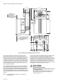
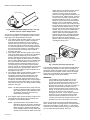
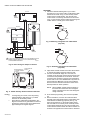
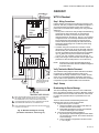
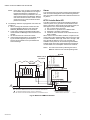
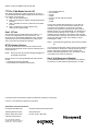
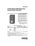
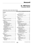
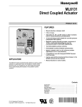
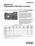
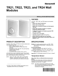
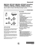
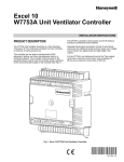
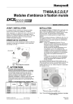
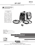
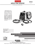
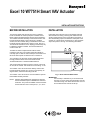
Excel 10 W7751H Smart VAV Actuator
INSTALLATION INSTRUCTIONS
BEFORE INSTALLATION
INSTALLATION
The W7751H Smart VAV Actuator is a factory-combined
Excel 10 Variable Air Volume (VAV) Box Controller and an
ML6174 Direct-Coupled Actuator with De-clutch mechanism.
The actuator/controller assembly is field mounted to the VAV
box damper shaft similar to the mounting of a standard
actuator, and the controller wiring is terminated to the screw
terminals that are located under a snap-on cover. See Fig. 1.
The Smart VAV Actuator is a Free Topology Transceiver (FTT)
LONMARK® compliant controller. The W7751H2025 is for
smoke control use.
Horizontally mount the W7751H on the damper shaft and
allow clearance for wiring, servicing and module removal.
Avoid mounting the W7751H in areas where acid fumes or
other deteriorating vapors can attack the metal parts of the
actuator, or in areas where escaping gas or other explosive
vapors are present. See Fig. 2 for mounting dimensions.
60
CW
45
The ML6174 Direct-Coupled Actuator with De-clutch
mechanism (see Fig. 2 for location) allows the installer to
manually open or close the VAV box damper connected to the
W7751H without power or software tool to command it.
CCW
NOTE: Mounting thermostat/sensor greater than 20 ft from
the W7751H2025 requires 14506944-001 Transient
Protectors. They must be installed on the thermostat/
sensor leads from the T7770C pins 3, 4, 5, 6, and 7.
60
The actuator on the W7751H can accommodate the optional
field-installed auxiliary switches.
CCW
The actuator on the W7751H mounts directly onto the VAV
box damper shaft and has up to 70 lb-in. torque (8 Nm), 90
degree stroke, and 90 second timing at 60 Hz.
45
Triac output loads must draw a minimum current of 25 mA at
24 Vac, 60 Hz nominal. Triac maximum current rating: 77 mA.
CW
The controller in the W7751H contains a Microbridge flowthrough pressure sensor and communicates via the
78 kilobaud Echelon® LONWORKS® Bus Network.
M19924
Fig. 1. Excel 10 Smart VAV Actuator.
IMPORTANT
The assembly is intended only for horizontal shaft
mounting, to assure proper heat dissipation from the
controller housing. The Smart VAV Actuator must not
be mounted with the controller at the top.
95-7553-04
EXCEL 10 W7751H SMART VAV ACTUATOR
4-1/16 (103)
1-13/16 (46)
1-5/16 (33)
3-5/8 (92)
CW
60
CCW
MAINTAIN A
MINIMUM DISTANCE
OF 3 IN. (76 MM)
FROM OTHER
DEVICES OR PANELS
FOR REMOVING
CONTROLLER COVER
1
(25)
60
CW
1-13/16
(46)
CCW
45
45
5-7/8
(149)
DE-CLUTCH
LEVER
3-3/4 (95)
MAINTAIN A MINIMUM DISTANCE
OF 4 IN (100 MM) FROM OTHER
DEVICES OR PANELS FOR
ATTACHING PNEUMATIC AIR
FLOW TUBING
3-3/4
(95)
DE-CLUTCH
LEVER
2-1/8
(54)
3/4
(19)
1-15/16 (49)
3/4
(19)
M10523
Fig. 2. W7751H mounting dimensions in in. (mm).
The W7751H assembly is field mounted to the VAV box
damper shaft, the same as used for a typical actuator. The
actuator on the W7751H opens or closes a damper by driving
the damper shaft in either the counterclockwise (CCW) or
clockwise (CW) direction. The actuator has a mounting tab on
the bottom for securing to a VAV box damper. The mounting
tab is accessible through a hole in the controller with its cover
removed (see Fig. 3). The tab is sized for a 1/4 in. (6 mm)
screw or pin (not included).
The controller enclosure on the W7751H is constructed of a
sheet metal housing and a plastic snap-on cover. Controller
wiring on the W7751H is terminated to screw terminal blocks
located under the snap-on cover. See Wiring section. The
sheet metal housing has two 1/2 inch (13 mm) knockouts (see
Fig. 2) compatible with 1/2 inch (13 mm) or 3/4 inch (19 mm)
conduit.
NOTE: The assembly is intended only for mounting to a
horizontal shaft.
95-7553—04
2
The W7751H actuator is shipped in the fully clockwise (CW)
position (90 degree). The W7751H Assembly must be
mounted to a horizontal damper shaft to assure proper heat
dissipation from the controller housing. Mount the W7751H so
that the actuator is parallel with the VAV box damper housing.
In general, it is recommended that a washer or spacer be
added between the VAV box damper housing and the actuator
mounting tab to keep them parallel. See Fig. 4.
CAUTION
Equipment Damage Hazard.
Mounting actuator unevenly with damper housing
can damage actuator.
Mount actuator flush with damper housing or add
spacer between mounting tab and damper box
housing. (See Fig. 4.)
EXCEL 10 W7751H SMART VAV ACTUATOR
CW
CW
45
CCW
CCW
CCW
60
CW
60
60
CW
CCW
45
45
60
45
PULL TOP OF
COVER OUT,
THEN DOWN,
FOR REMOVAL
CIRCUIT BOARD
TERMINAL BLOCKS
MOUNTING TAB
M10000
Fig. 3. Cover removal and mounting tab/terminal block access.
3.
1MM (1/32 IN.)
4.
The direction the damper shaft rotates to open the
damper (CW or CCW), see Fig. 5.
The damper opening angle (45, 60, or 90 degrees).
TYPE A DAMPER
AIR
FLOW
CW TO OPEN, CCW TO CLOSE
TYPE B DAMPER
AIR
FLOW
M2067B
1MM
(1/32 IN.)
CCW TO OPEN, CW TO CLOSE
Fig. 5. Determining rotation direction (CW or CCW)
for damper opening.
M20884
Fig. 4. Mounting W7751H to VAV box damper housing
when actuator is not parallel to VAV box damper housing.
Before mounting the W7751H onto the VAV box damper shaft,
determine the following:
1. The damper shaft diameter, 3/8 to 1/2 in. (10 to 13 mm).
2. If the length of the VAV box damper shaft is less than
1-3/8 in. (35 mm), use the Short Shaft Adapter Kit (not
included), part no. 4074EVK.
3
If damper shaft diameter is 3/8 inch (10 mm) round or square,
use part 201391 Shaft Adapter (shipped with the W7751H
Smart VAV Actuator). Ensure it is placed opposite set screws.
See Fig. 6. The adapter centers a 3/8 in. (10 mm) shaft in the
hub. Failure to use the adapter on a 3/8 in. (10 mm) shaft
causes the mounting tab to loosen. A 1/2 in. (13 mm) shaft
does not require the use of the adapter.
95-7553—04
EXCEL 10 W7751H SMART VAV ACTUATOR
M2064
Fig. 6. Use Damper Shaft Adapter for 3/8 in. (10 mm)
diameter round or square damper shafts.
The W7751H is shipped with the actuator rotated in the fully
clockwise (CW) position. The installation procedure varies
depending on the damper direction and angle:
1. If the damper rotates clockwise (CW) to open, and the
angle of the damper open to closed is 90 degrees,
manually open the damper fully to the clockwise
direction and mount the W7751H to the VAV damper
box and shaft. Tighten the Allen set screws. The part
no. 201614 Range Stop Pin, which is shipped with the
W7751H Smart VAV Actuator, is unnecessary. When
the W7751H closes, the damper rotates CCW 90
degrees to fully close.
2. If the damper rotates clockwise (CW) to open, and the
angle of the damper open to closed is 45 or 60 degrees,
manually open the damper fully to the clockwise
direction and mount the W7751H to the VAV damper
box and shaft. Tighten the Allen set screws. Insert the
part no. 201614 Range Stop Pin, which is shipped with
the W7751H Smart VAV Actuator, in either the 45 or
60 degree CCW slot, whichever applies (see Fig. 7).
The range stop pin must go all the way through the
housing. The pin can only be installed in the CCW slots
when the actuator is in the CW position. When the
W7751H closes, the damper rotates CCW either 45 or
60 degrees to fully close.
3. If the damper rotates counterclockwise (CCW) to open,
and the angle of the damper open to closed is
90 degrees, manually close the damper fully to the
clockwise direction and mount the W7751H to the
damper box and shaft. Tighten the Allen set screws.
The part no. 201614 Range Stop Pin, which is shipped
with the W7751H Smart VAV Actuator, is unnecessary.
When the W7751H opens, the damper rotates CCW 90
degrees to fully open.
NOTE: Be aware that the damper is closed. Until the
W7751H is powered and the damper is driven
open, starting the fan system with all the VAV
box dampers closed can cause duct overpressurization and damage.
4.
If the damper rotates counterclockwise (CCW) to open,
and the angle of the damper open to closed is 45 or
60 degrees, see the following NOTE.
NOTE: Special precautions must be taken for this
application. Mount the W7751H to the damper
box. (Do not tighten the Allen set screws yet).
Before the part no. 201614 Range Stop Pin,
which is shipped with the W7751H Smart VAV
Actuator, can be inserted in either the 45 or 60
95-7553—04
4
CW
RANGE
STOP PIN
60
CCW
SHAFT ADAPTER
degree CW slot, the damper actuator must be
driven fully open (CCW). To do this, the
controller on the W7751H must be wired,
powered, and connected to the portable PC via
the Serial LonTalk® Adapter (SLTA). The SLTA
connects to the controller on the W7751H via
the jack for Network Access on T7770 Wall
Module or by the B-Port on the Q7750A Zone
Manager. From E-Vision Software, drive the
actuator on the W7751H fully CCW, and insert
the range stop pin in either the 45 or 60 degree
CW slot, whichever applies (see Fig. 7). The
range stop pin must go all the way through the
housing. The pin can only be installed in the
CW slots when the actuator is in the CCW
position. (Disconnect the portable PC once
programming has been completed.) Manually
open the damper shaft fully (CCW) and then
tighten the Allen set screws. When the
W7751H closes, the damper will rotate CW 45
or 60 degrees to fully close.
CW
45
CCW
ACTUATOR
PLATES
60
45
M10002
Fig. 7. Properly inserting range stop pin.
The Honeywell Software Tool’s (miscellaneous parameter for
rotation direction) defaults to CW to Open, which applies to
the damper direction and angle in items 1 and 2 above. The
parameter must be changed to CCW to Open if the damper
shaft rotates in this direction, which applies to the damper
direction and angle in items 3 and 4 above.
IMPORTANT
It is advisable to leave the dampers in an open
position after W7751H installation to avoid the
possibility of overpressurizing the ductwork on fan
startup. Use the De-clutch lever (see Fig. 2 for
De-clutch lever location) to open the box damper on
W7751H controllers that are powered down, to
prevent overpressurization in the ductwork on fan
startup. To use the De-clutch lever, press and hold
the lever in the direction of the arrow (this
disengages the motor). Turn the damper shaft until
the damper is open and release the lever. When
power is restored to the W7751H controller, the
controller synchronizes the damper actuator so that
the damper is in the correct position upon startup.
When a range stop pin is used with a field-added auxiliary
switch, the tab on top of the range stop pin must point inward
toward the VAV damper box shaft. See Fig. 11. This allows
clearance for the auxiliary switch housing. To remove the pin,
pry it up with a flathead screwdriver. See Fig. 8.
EXCEL 10 W7751H SMART VAV ACTUATOR
—
IMPORTANT
The minimum position set screw on the actuator is
not available on the W7751H device.
To prevent VAV air flow connector breakage, use
caution when removing tubing from it. Always pull
straight away from connector; never remove by
pulling at an angle.
Wiring
SCREWDRIVER
All wiring must comply with applicable electrical codes and
ordinances, or as specified on installation wiring diagrams.
NOTES:
—
M2065
Fig. 8. Lifting a range stop pin out of its slot.
Piping
Air flow Pickup
Connect the air flow pickup to the two connectors on the
controller of the W7751H. See Fig. 9.
—
—
CW
AIRFLOW
DIRECTION
60
—
CCW
AIRFLOW
DP PICKUP
CW
45
60
CCW
Power
45
The 24 Vac power from an energy limited Class II Power
Source must be provided to each Smart VAV Actuator. To
conform to Class II restrictions, transformers must not be
larger than 100 VA. The maximum current draw at 24 Vac is
1.25A.
– LO
+ HI
M10003
Fig. 9. Smart VAV Actuator air flow pickup connections.
NOTES:
—
—
Use 1/4 in. (6 mm) outside diameter with 0.040 in.
(1 mm) wall thickness plenum rated 1219 FR
(94V-2) pneumatic tubing.
Always use a fresh cut on the end of the tubing
that connects to the air flow pickups and the
connectors on the VAV controllers.
Connect the high pressure or upstream tube to the plastic
restrictor labeled (+ HI) or P1 and the low pressure or
downstream tube to the restrictor labeled (- LO) or P2. See
labeling in Fig. 9.
NOTES:
—
—
—
For multiple controllers operating from a single
transformer, the same side of the transformer
secondary must be connected to the same input
terminal in each controller and the ground
terminals (3 on the W7751H, 28 on the W7751B,
and 32 on the W7751D,F) must be connected to a
verified earth ground for each controller in the
group. See Fig. 10. (Controller configurations are
not necessarily limited to three devices, but the
total power draw including accessories cannot
exceed 100 VA when powered by the same
transformer. See System Engineering form
74-2949 for power wiring recommendations.)
All loads on an Excel 10 Controller must be
powered by a single transformer.
Keep the earth ground connection (terminal 3)
wire run as short as possible. Refer to Fig. 16.
Do not connect the analog ground terminal (5) to
earth ground. Refer to Fig. 16.
IMPORTANT
— Power must be off prior to connecting to or removing
connections from output terminals 9 and 10.
— Use the heaviest gauge wire available, up to
14 AWG (2.0 mm2) with a minimum of 18 AWG
(1.0 mm2), for all power and earth ground wiring. For
nonplenum, open areas, run cables exposed (or in
conduit, if required).
— If the W7751H Smart VAV Actuator is used on
Heating and Cooling Equipment (UL 1995, US
only) and the transformer primary power is more
than 150 volts, connect the transformer secondary to
earth ground, see Fig. 10.
NOTE: Maintain a three-inch (76 millimeter) separation
between Triac outputs and LONWORKS® Bus wiring
throughout installation.
If controllers are mounted in unusually dusty or
dirty environments, a 5-micron disposable air filter
is recommended for the high pressure line
(marked as +) connected to the air flow pickup.
When using twin tubing from pickup, split pickup
tubing a short length to accommodate connections.
Tubing from air flow pickup to VAV controller
should not exceed three feet (0.914m). Lengths
longer than this can degrade flow sensing
accuracy.
5
Auxiliary Switches
The 201052A,B,C Auxiliary Switch can be used with the
W7751H. It allows for control of equipment external to the
actuator (for example, electric reheat coils or fan) at an
adjustable point in the stroke (from 0 to 90 degrees) of the
actuator. The 201052 Switch is field-added. Self-tapping
Phillips head screws are included with the switch. The switch
can be mounted only one way (see Fig. 11) with the switch
contacts pointed to the top of the actuator.
95-7553—04
EXCEL 10 W7751H SMART VAV ACTUATOR
PROCEDURE
1. Determine desired switching action (i.e, if switch
energizing is to occur during CW or CCW rotation). With
switch cam as shown in Fig. 12, the normally closed
contact opens in CCW rotation. The normally open
contact closes. Conversely, with switch cam as shown
in Fig. 13, the normally closed contact opens during CW
rotation and the normally open contact closes.
W7751B
28
EARTH
GROUND
9
10
W7751H OR J
COM
NO
NC
W7751D,F
32
CCW
24V
COM
2
3
4
COM
COM
1
M2160
24V
24V
EARTH
GROUND
1
2
COM
24
VAC
120/240
VAC
Fig. 12. Switching configuration for CCW rotation
(top view).
3
NO
NC
EARTH
GROUND
TRANSFORMER
1
CW
1
EARTH
GROUND
IF THE W7751 CONTROLLER IS USED IN UL 1995 EQUIPMENT AND THE
PRIMARY POWER IS MORE THAN 150 VOLTS, GROUND ONE SIDE
OF TRANSFORMER SECONDARY.
M10524A
M2161
Fig. 10. Power wiring for multiple controllers.
RANGE STOP PIN
POINTED TOWARD
SHAFT
75
90
Fig. 13. Switching configuration for CW rotation
(top view).
201052 AUXILARY
SWITCH
2.
3.
N N
C O
COM
60
45
30
15
0
NOTE: When installed, angular position indicator on
the switch face moves from 90 to 0 degrees
during CCW motion and from 0 to 90 degrees
during CW motion.
M10005
Fig. 11. 201052 Auxiliary Switch mounted on W7751H.
NOTES:
—
—
95-7553—04
Align switch hub with actuator set screws. Mount switch
on actuator and tighten the three captive screws.
Connect controller with laptop PC. To do this, the
controller on the W7751H must be wired, powered, and
connected to the portable PC via the SLTA. The SLTA
connects to the controller on the W7751H via Network
Access Jack on the T7770 Wall Module or by B-Port on
the Q7750A Zone Manager. From E-Vision Software,
drive the W7751H actuator and halt the motion at the
desired position for switch operation.
If a range stop pin is used, it must be pointing
inward toward the shaft (see Fig. 11) to allow
clearance for the auxiliary switch.
Each switch is independently adjustable in twodegree increments to any point within the travel of
the actuator. Switches have a fixed differential of
approximately three angular degrees.
6
4.
5.
Once finished programming, disconnect the portable
PC.
With a screwdriver, move the cam inside the switch
assembly to the appropriate position, remembering cam
travel direction for switching purposes (see Fig. 14)
when turning switch on or off. Monitor switch closure
with ohmmeter for a continuity check. Normally closed
contact should measure zero ohms and normally open
contact should measure infinite ohms when switch is not
activated. The opposite is true when switch is activated.
EXCEL 10 W7751H SMART VAV ACTUATOR
• Approved cable type is Level IV 22 AWG (0.34 mm2)
plenum or non-plenum rated unshielded, twisted pair, solid
conductor wire:
— For nonplenum areas, use CMP listed cable.
— In plenum areas, use CMP listed cable.
• Do not bundle output wires with sensor, digital input or
LONWORKS® Bus wires.
• Ensure that neither LONWORKS® Bus wire is grounded.
• In noisy (high EMI) environments, avoid wire runs parallel
to noisy power cables, motor control centers, or lines
containing lighting dimmer switches. Keep at least 3 in.
(76 mm) of separation between noisy lines and
LONWORKS® Bus cable.
• Do not use different wire types or gauges on the same
LONWORKS® Bus segment:
— Step changes in line impedance characteristics cause
unpredictable reflections on the LONWORKS® Bus.
SWITCH CAMS
M2076A
Fig. 14. Auxiliary switch cam adjustment.
NOTE: For 2 or 3 switch models, cams align with their
respective switches and are individually set
using the same procedure described above.
6.
Ensure switch activation at the desired degree of stroke
by commanding the actuator to both fully open and fully
closed; see step 3.
Wiring Details
Wire to the terminal blocks as follows:
1. Strip 3/16 in. (5 mm) insulation from the conductor.
2. Insert the wire in the required terminal location and
tighten the screw to complete the termination.
NOTE: With the exception of 14 AWG (2.0 mm2), if
inserting two or more wires into one terminal
location, twist wires together before inserting
them. See Fig. 15. Deviation from this rule can
result in improper electrical contact.
NOTE: Switches can also be preset prior to actuator
installation if angular switch position is known.
Communications
Refer to LONWORKS® Bus Wiring Guidelines, form 74-8565,
for complete description of LONWORKS® Bus network topology
rules.f
If a longer LONWORKS® Bus network is required, a Q7740A
2-way or Q7740B 4-way Repeater can be added to extend
LONWORKS® Bus length, only if this is an Energy
Management (PAZX) Bus.
The controller on the W7751H has the terminal arrangement
shown in Fig. 16. Fig. 16 through 21 provide detailed wiring
diagrams for the W7751H. Refer to installation diagrams for
specific wiring.
NOTE: Ensure Configuration DIP Switch is set as shown in
Fig. 19. Switches 1 through 3 set ML7984B Valve
Actuator timing to match W7751H outputs (0.1 sec.
minimum with maximum time of 25.6 sec.). Switch 4
determines actuator action (Off = Direct Acting, On =
Reverse Acting).
IMPORTANT
The Q7740A,B Repeaters cannot be used in
smoke control applications.
A Q7751A Router can only be added to an Energy
Management Bus to partition system into two segments
(effectively doubling LONWORKS® Bus length). Only one
router is allowed with each Excel 10 Zone Manager (or Excel
15 Building Manager), and each network segment can have a
maximum of one repeater.
1/2
(13)
1. STRIP 1/2 IN.
(13 MM) FROM
WIRES TO BE
ATTACHED AT
ONE TERMINAL.
CONTROLLER OR
WALL MODULE
E-BUS CONNECTOR
TERMINALS
Pull the cable to each device on the LONWORKS® Bus and
connect to communication terminals 11 and 12 (W7751H).
IMPORTANT
Screw type terminal blocks are designed to accept
no more than one 14 AWG (2.0 mm2) conductor.
Multiple 14 AWG (2.0 mm2) wires can be connected
with a wire nut. Include a pigtail with this wire group
and attach the pigtail to the individual terminal block.
Notes on LonWorks® Bus Communications Wiring:
• All field wiring must conform to local codes and ordinances
(or as specified on the installation drawings).
7
2. TWIST WIRES
TOGETHER
WITH PLIERS
(A MINIMUM OF
THREE TURNS).
3. CUT TWISTED END OF WIRES TO
3/16 IN. (5 MM) BEFORE INSERTING
INTO TERMINAL AND TIGHTENING
SCREW. THEN PULL ON EACH WIRE
IN ALL TERMINALS TO CHECK FOR
GOOD MECHANICAL CONNECTION.
M11413
Fig. 15. Attaching two or more wires at terminal blocks.
95-7553—04
EXCEL 10 W7751H SMART VAV ACTUATOR
COMM
OUT
COMM
OUT
2
2
AIR FLOW
DP PICKUP
E-BUS
GND
SET PT
E-BUS
JACK FOR
E-BUS
NETWORK
ACCESS
T7770C
WALL
MODULE
AIR FLOW
DP PICKUP
AIR FLOW
DIRECTION
SENSOR
LED
JACK FOR
E-BUS
NETWORK
ACCESS
T7770C
WALL
MODULE
BYPASS
9 8 7 6 5 4 3 2 1
E-BUS
GND
E-BUS
SET PT
SENSOR
BYPASS
LED
9 8 7 6 5 4 3 2 1
AIR FLOW
DIRECTION
LOW
W7751H
MICROBRIDGE
DP SENSOR
LOW
HI
TRIAC
EQUIVALENT
CIRCUIT
NOT EARTH GROUND
W7751H
MICROBRIDGE
DP SENSOR
HI
TRIAC
EQUIVALENT
CIRCUIT
2
3
WALL MODULE
4
5
6
7
OUT 2
2
24 VAC
1
OUT 1
2
LED
12
BYPASS
11
SENSOR
10
GND
E-BUS
9
SET PT
8
COM
7
EARTH
6
24 VAC
5
OUT 2
WALL MODULE
4
OUT 1
LED
BYPASS
3
SENSOR
2
GND
COM
EARTH
1
SET PT
24 VAC
NOT EARTH GROUND
E-BUS
9
10
11
8
12
2
COMM
IN
24 VAC
2
COMM
IN
EARTH
GROUND
1
OPEN
SIGNAL
1
EARTH
GROUND
CLOSED
SIGNAL
NOTE: LOAD POWER WIRE
IS CONNECTED
TO TERMINAL 1.
NOTE: LOAD POWER WIRE STEM COM STEM
IS CONNECTED
DOWN
UP
TO TERMINAL 1.
M6410 SERIES 60
VALVE ACTUATOR
2
1
EARTH GROUND WIRE LENGTH SHOULD BE HELD TO A MINIMUM. USE
THE HEAVIEST GAUGE WIRE AVAILABLE, UP TO 14 AWG (2.0 MM2)
WITH A MINIMUM OF 18 AWG (1.0 MM2), FOR EARTH GROUND WIRE.
2
CONTACTORS
24 VAC ONLY
EARTH GROUND WIRE LENGTH SHOULD BE HELD TO A MINIMUM. USE
THE HEAVIEST GAUGE WIRE AVAILABLE, UP TO 14 AWG (2.0 MM2)
WITH A MINIMUM OF 18 AWG (1.0 MM2), FOR EARTH GROUND WIRE.
TO ASSURE PROPER ELECTRICAL CONTACT, WIRES MUST BE TWISTED
TOGETHER BEFORE INSERTING INTO THE TERMINAL BLOCK.
M10526
TO ASSURE PROPER ELECTRICAL CONTACT, WIRES MUST BE TWISTED
TOGETHER BEFORE INSERTING INTO THE TERMINAL BLOCK.
M10525
Fig. 16. W7751H modulating reheat valve wiring diagram.
(For Note 2 instructions, refer to Fig. 15.)
95-7553—04
STAGE 2
LINE POWER
TWO OR THREE-WAY VALVE
1
STAGE 1
8
Fig. 17. W7751H 2-stage reheat wiring diagram.
(For Note 2 instructions, refer to Fig. 15.)
EXCEL 10 W7751H SMART VAV ACTUATOR
CHECKOUT
COMM
OUT
W7751H Checkout
2
Step 1. Wiring Connections
JACK FOR
E-BUS
NETWORK
ACCESS
T7770D
WALL
MODULE
AIR FLOW
DP PICKUP
Inspect all wiring connections at the W7751H and the T7770
terminals, and verify compliance with installation diagrams. If
any wiring changes are required, first be sure to remove
power from the controller before starting work. Pay particular
attention to:
— 24 Vac power connections. Verify multiple controllers being
powered by the same transformer are wired with the
transformer secondary connected to the same input
terminal numbers on each W7751. See Fig. 10. (Controller
configurations are not necessarily limited to three devices,
but the total power draw including accessories cannot
exceed 100 VA when powered by the same transformer.
See System Engineering form 74-2949 for power wiring
recommendations.)
— Controller wiring. Be sure that each controller is wired
(terminal 3 on the W7751H, 28 on the W7751B, and 32 on
the W7751D,F) to a verified earth ground using a wire run
as short as possible with the heaviest gauge wire available,
up to 14 AWG (2.0 mm2) with a minimum of 18 AWG
(1.0 mm2) for each controller in the group. See Fig. 10.
— Verify Triac wiring to external devices uses the proper load
power/24 Vac Hot terminal (terminal 1 on the W7751H).
E-BUS
GND
E-BUS
SET PT
SENSOR
LED
BYPASS
9 8 7 6 5 4 3 2 1
AIR FLOW
DIRECTION
LOW
W7751H
MICROBRIDGE
DP SENSOR
HI
TRIAC
EQUIVALENT
CIRCUIT
5
6
7
8
OUT 2
WALL MODULE
4
OUT 1
LED
BYPASS
3
SENSOR
EARTH
2
GND
COM
1
SET PT
24 VAC
NOT EARTH GROUND
E-BUS
9
10
11
NOTE: All wiring must comply with applicable electrical
codes and ordinances. Refer to installation diagrams
for specific wiring.
12
Verify Termination Module Placement
2
2
24 VAC
The installation wiring diagrams should indicate the locations
for placement of Termination Module(s). Refer to the
LONWORKS® Bus Wiring Guidelines, form 74-2865, and the
Excel 10 FTT Termination Module Installation Instructions,
form 95-7554. Correct placement of the termination module(s)
is required for proper LONWORKS® Bus communications.
2
COMM
IN
1
EARTH
GROUND
WIRED FOR MODULATING
OR STAGED REHEAT. SEE
FIG. 17 OR FIG. 18.
Step 2. Startup
Broadcasting the Service Message
The Service Message allows a device on the LONWORKS®
Bus to be positively identified. The Service Message contains
the controller neuron ID number and, therefore, can be used
to confirm the physical location of a particular Excel 10 in
building.
C7770A AIR
TEMPERATURE SENSOR
1
EARTH GROUND WIRE LENGTH SHOULD BE HELD TO A MINIMUM. USE
THE HEAVIEST GAUGE WIRE AVAILABLE, UP TO 14 AWG (2.0 MM2)
WITH A MINIMUM OF 18 AWG (1.0 MM2), FOR EARTH GROUND WIRE.
2
TO ASSURE PROPER ELECTRICAL CONTACT, WIRES MUST BE TWISTED
TOGETHER BEFORE INSERTING INTO THE TERMINAL BLOCK.
3
NOTE: AIR TEMPERATURE SENSOR CANNOT BE USED WITH EITHER THE
T7750B OR C WALL MODULE.
M10527A
Fig. 18. W7751H discharge air sensing
(For Note 2 instructions, refer to Fig. 15.)
9
There are three methods of broadcasting the Service
Message from an Excel 10 W7751H Controller:
1. Physical service pin on controller:
a. Remove the plastic cover and the white button is
located next to the terminal strip.
b. Momentarily pressing this service pin broadcasts
the Service Message on the network.
2. Using the wall module bypass pushbutton:
a. By pressing the wall module bypass/override button
for more than four seconds, the controller sends the
Service Message.
b. This functionality is supported in firmware version
1.2.15 or higher.
95-7553—04
EXCEL 10 W7751H SMART VAV ACTUATOR
Alarms
NOTE: During item 2, the occupancy override state of
the controller changes based on how long the
bypass/override button is depressed. For
example, if the button is pressed for 6 sec., the
node sends the Service Pin Message, AND the
node enters Continuous Unocc mode. To clear
Continuous Unocc mode, the button must be
pressed momentarily.
3.
The commissioning tool is used to perform the ID Assignment
task. Once the ID Assignment and commissioning has been
done, check the controller status LED to determine if there are
any alarms.
W7751 Controller Status LED
The LED on the front of a W7751H Controller (located just
under the plastic cover), provides a visual indication of the
status of the device. When the W7751H receives power, the
LED appears in one of the following allowable states:
1. Off—no power to the processor.
2. Continuous on—processor is in initialized state.
3. Slow blink—controlling, normal state.
4. Fast blink—when the Excel 10 VAV Controller has an
alarm condition.
When an Excel 10 has an alarm condition, it reports it to the
central node on the LONWORKS® Bus. Also, the Excel 10 VAV
Controller variables, AlarmLogX, where X is 1 through 5, that
store the last five alarms to occur in the controller, are
available. These points can be viewed through workstation
software. Refer to the VAV System Engineering Guide form,
74-2949 Table 12 for a description of the Excel 10 Alarms.
The following method is only supported on E-Vision and
LONSPEC™:
a. When an Assign ID command is issued from the
Honeywell Software listed, the node enters the
SERVICE_MESSAGE mode for five minutes.
b. In this mode, pressing the bypass/override button
causes the Service Message to be broadcast on the
network.
c. All other functions are normal in this mode.
d. If the bypass/override button is not available, shorting the controller Bypass Input terminals (on
W7751H short terminals 5 and 7) broadcasts the
Service Message.
NOTE: The node can be reset by switching the node to
MANUAL and then to the normal operating mode.
ML7984B
TRIAC
EQUIVALENT
CIRCUIT
T6
T5
C
PWM OUTPUT
FROM CNTRL
24 (H)
W7751H
NOT EARTH GROUND
24 (N)
REHEAT VALVE
ACTUATOR
PWM (H 24 VAC)
PWM VALVE ACTUATOR
B
W
R
10
11
12
T6
T5
C
PWM OUTPUT
FROM CNTRL
E-BUS
9
PWM (H 24 VAC)
8
24 (H)
7
24 (N)
6
OUT 2
5
OUT 1
BYPASS
WALL MODULE
4
ML7984B
PWM VALVE ACTUATOR
LED
3
SENSOR
EARTH
2
GND
COM
1
SET PT
24 VAC
2
B
2
1
1
24 VAC
R
2
3
4
ON
1
2
MAKE SURE ALL TRANSFORMER/POWER WIRING IS AS SHOWN;
REVERSING TERMINATIONS WILL RESULT IN EQUIPMENT MALFUNCTION.
TO ASSURE PROPER ELECTRICAL CONTACT, WIRES MUST
BE TWISTED TOGETHER BEFORE INSERTING INTO THE TERMINAL BLOCK.
OFF
CONFIGURATION DIP SWITCHES
LOCATED ADJACENT TO THE INPUT
TERMINAL BLOCK ON ML7948B
Fig. 19. W7751H to PWM Valve Actuator.
95-7553—04
W
PERIPHERAL REHEAT
VALVE ACTUATOR
10
M10528
EXCEL 10 W7751H SMART VAV ACTUATOR
SERIES OR
PARALLEL
FAN
W7751H
TRIAC
EQUIVALENT
CIRCUIT
NOT EARTH GROUND
ML7984B
E-BUS
9
10
11
12
T6
T5
C
PWM OUTPUT
FROM CNTRL
8
PWM (H 24 VAC)
7
24 (N)
6
?24 (H)
5
OUT 2
WALL MODULE
4
CONTACTOR
(24 VAC)
OUT 1
BYPASS
LED
3
SENSOR
EARTH
2
GND
COM
1
SET PT
24 VAC
PWM VALVE ACTUATOR
B
W
R
2
REHEAT
VALVE
ACTUATOR
1
24 VAC
1
MAKE SURE ALL TRANSFORMER/POWER WIRING IS AS SHOWN; REVERSING TERMINATIONS WILL RESULT IN EQUIPMENT MALFUNCTION.
2
TO ASSURE PROPER ELECTRICAL CONTACT, WIRES MUST BE TWISTED TOGETHER BEFORE INSERTING INTO THE TERMINAL BLOCK.
M10529
Fig. 20. W7751H to PWM Valve Actuator and series or parallel fan.
5
6
7
8
M
M
DECREASE
11
INCREASE
10
24 (N)
E-BUS
9
24 (H)
OUT 2
WALL MODULE
4
OUT 1
LED
BYPASS
SENSOR
3
GND
COM
EARTH
2
SET PT
24 VAC
1
MMC325 PNEUMATIC
TRANSDUCER
24 (N)
TRIAC
EQUIVALENT
CIRCUIT
NOT EARTH GROUND
?24 (H)
W7751H
4
B
12
2
3
1
PNEUMATIC
VALVE
24 VAC
1
REVERSE WIRES (INCREASE/DECREASE) TO REVERSE ACTION (DIRECT/REVERSE).
2
MAKE SURE ALL TRANSFORMER/POWER WIRING IS AS SHOWN; REVERSING TERMINATIONS WILL RESULT IN EQUIPMENT MALFUNCTION.
3
OPTIONAL 24 VAC WIRING TO NEXT CONTROLLER.
4
USE 1/4 IN. (6 MM) MINIMUM PNEUMATIC TUBING. BRANCH LINE MUST BE 6 FT (1.8M) OR LONGER.
M10530
Fig. 21. W7751H to pneumatic transducer.
11
95-7553—04
EXCEL 10 W7751H SMART VAV ACTUATOR
T7770C or D Wall Module Override LED
The remote override LED, located on either the T7770C or
T7770D Wall Module will display the Manual Override mode of
the controller. The modes are:
1. LED = Off. No override active.
2. LED = Continuously On. Bypass mode (timed Occupied
override).
3. LED = One flash per second. Continuous Unoccupied
override.
4. LED = Two flashes per second. Remote only,
continuous Occupied override.
Step 3. I/O Tests
The controller can be configured using the LONSPEC™, or
E-Vision PC configuration tool. Once this is done, the
W7751H can be commanded to MANUAL mode, and each
output and input can be exercised/viewed to verify proper
wiring connections and equipment operation.
W7751H Actuator Checkout
To check out the actuator on the W7751H, determine the
direction the damper shaft moves to open the damper (CW or
CCW). See Fig. 5.
NOTE: Devices for use only if used for Energy Management:
Q7740A,B and Q7751A.
Devices for use on an Energy Management and/or Smoke
Control:
— 14507287 Series Power Supplies,
— W7751B2010, W7751D2016, W7751F2011,
—
—
—
—
—
—
—
W7751H2025 Series 9,
W7761A2010,
Q7750,
Q9200,
XFL521, XFL522, XFL523, XFL524,
XL500,
XLINK.
Connect the controller with the laptop PC. To do this, the
controller on the W7751H must be wired, powered, and
connected to the portable PC via the SLTA. The SLTA
connects to the controller on the W7751H via the Jack for
Network Access on T7770 Wall Modules or by the B-Port on
the Q7750A Zone Manager. From LONSPEC™, or E-Vision
Software, drive the actuator on the W7751H open and then
closed. Observe the operation of the actuator; if the damper is
closed, it should begin to open. If the damper is open, it
should begin to close.
NOTE: Once finished programming, disconnect the portable
PC.
If no movement is observed, check to see if 24 Vac is present
at the controller on the W7751H. With proper wiring, 24 Vac
present, and proper commands from the software, the
actuator should operate properly. If not, the W7751H Smart
VAV Actuator may need to be replaced.
Step 4. Verify Sequences of Operation
For the detailed descriptions of the sequences of operation,
see the Excel 10 VAV System Engineering form 74-2949.
LONWORKS® and LONTALK® are registered trademarks of Echelon® Corporation.
LONSPEC™ is a trademark of Echelon® Corporation.
Automation and Control Solutions
Honeywell International Inc.
Honeywell Limited-Honeywell Limitée
1985 Douglas Drive North
35 Dynamic Drive
Golden Valley, MN 55422
Toronto, Ontario M1V 4Z9
customer.honeywell.com
® U.S. Registered Trademark
© 2008 Honeywell International Inc.
95-7553—04 M.S. Rev. 03-08