1
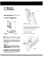
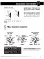
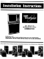
30” BUILT-IN
MICROWAVE OVEN
COMBINATION
IMPORTANT
INSTALLER: LEAVE THESE INSTRUCTIONS WITH THE HOMEOWNER.
HOMEOWNER: RETAIN THESE INSTRUCTIONS FOR FUTURE REFERENCE.
ave Ovens, Compactors,
Room Air Conditioners,
Dehumidifiers,
Automatic Washers, Clothes Dryers, Freezers, Refrigerator-freezers,
Ice Makers,Dishwasl
PRECAUTIONS
TO AVOID
POSSIBLE EXPOSURE TO
EXCESSIVE MICROWAVE ENERGY
Before you begin
II
Do not attempt to operate this oven with the door open
since open-door operation can result in harmful exposure to microwave energy. It is important not to
defeat or tamper with the safety interlocks.
Read these instructions
completely
and carefully.
If followed, they will simplify the installation
job.
IMPORTANT:
Do not place any object between the oven front face
and the door or allow soil or cleaner residue to
accumulate on sealing surfaces.
Observe all governing codes and ordinances.
Failure to follow these instructions
could lead
to fire or electrical shock hazard.
Do not operate the oven if it is damaged. It is particularly
important that the oven door close properly and that
there is no damage to the:
1. Door (bent)
2. Hinges and latches (broken or loosened)
3. Door seals and sealing surfaces.
The oven should not be adjusted or repaired by anyone
except properly qualified personnel.
The oven should be checked for microwave leakage
by qualified service personnel after a repair is made.
A. Space requirements
Do not operate the oven if the door glass is broken.
2” MIN.
I
HOLE IN OVEN
SUPPORT
SURFACE
FOR CABLE
46-1 I/
;99-718”
1
FLEX.
CABLE
**28-l/2”
MINIMUM,
IF 20.518”
IS AVAILABLE
THE CUTOUT
SHOULD
BE MADE 285/8”.
The oven support surface may be solid plywood
or similar material but the contact surface must
be level from side to side and from front to rear.
This surface is 23/4” below the open lower door
height.
NOTE 1: The oven support surface must be flush
with the bottom of the cabinet cutout.
2
ELECTRICAL
JUNCTION
SUPPLY
BOX:
*RECOMMENDED
12” MINIMUM
DIMENSION
FOR 43-l/2”
HEIGHT
TO MICROWAVE
OVEN BOTTOM.
SEE NOTE
Do not seal range to cabinets.
1
B. Check microwave for
damage
Remove all packing material from the oven cavity.
When unpacking the unit, check for damage such as
misaligned door, damaged gaskets around the door,
or dents inside the oven or on the exterior. If there is
any damage, please do not operate the unit until it has
been checked by an authorized Whirlpool trained service technician.
C. Electrical requirements
IMPORTANT:
SAVE THESE INSTRUCTIONS
FOR THE
LOCAL ELECTRICAL INSPECTOR’S USE
A. This appliance must be connected to the proper
electrical voltage and frequency as specified on
nameplate. Models rated at 15 KW on 240 volts (11.25
KW on 208V) or more require a separate 50 amp circuit. Models rated less than 15KW on 240 volts (11.25
KW on 208V) require a separate 40 ampere circuit.
Fuse both sides of the line. DO NOT fuse the neutral.
A time delay fuse or circuit breaker is recommended.
Wire sizes must conform to the requirements of the National Electrical Code and/or local codes and ordinances for the kilowatt rating of the range. The
nameplate is located on the front frame behind the
microwave oven door.
NOTE: Wire sizes and connections must conform with
the fuse size and rating of the appliance in accordance
with National Electrical Code and local codes and ordinances. Do not use an extension cord.
B. The appliance should be connected to the fused
disconnect (or circuit breaker) box through flexible armored or non-metallic sheathed cable. The flexible armored cable extending from the appliance should be
connected directly to the junction box. The junction box
should be locat.ed as shown in Figure 1 on page 2 so
that as much slack as possible remains in the cable
between the box and the appliance so that it can be
moved if servicing is necessary.
C. A suitable strain relief must be provided to attach
the flexible armored cable to the junction box.
Begin the
installation
Remove racks and all other contents
before removing appliance.
-
from oven
A. Remove shipping skid
VIEW A
2. Put a nail (932” or smaller) or equivalent in the hole
in each of the hinges. Close the oven door until the
pins touch the oven front. See View 13.
3. The oven door can now be lifted off.
4. Reinstall oven door the same as on non-self cleaning models. (See page 5)
5. Reinstall
NOTE:
Before installing the oven in the cut-out, it may be
helpful to remove the lower oven door. See details
below.
Insert appliance into cut-out. Screws are provided for
fastening the front frame of the appliance to the cabinet.
The mounting holes in the front frame of appliance may
be used as a template to locate the appliance mounting screw holes.
CAUTION:
For your personal safety, and to minimize potential personal injury, this oven must be securely
fastened to the cabinet, using the four screws
that are provided.
TO REMOVE
OVEN DOOR-SELF-CLEANING
MODELS (Door to be removed for installation
only.
1. Remove the two screws, one on each side of the inner door panel. See View A.
4
the door mounting
screws.
Removing the oven door may make it easier to clean
the oven. To remove the door, first open it to the first
stop (about 4 inches or 10 cm). Take hold of both
sides of the door near the top; then lift it at the same
angle it is in.
TO REMOVE OVEN DOOR
(NON-SELF-CLEANING
MODELS)
With the door off, you will notice how the ends of
hinges slide into slots at the bottom corners of the
door. To put the door back on, fit both corners of the
door over the ends of the hinges. Push the door
down evenly, so neither corner gets ahead of the
other. When it reaches the bottom, you can close
the door. A safety latch will hold the door open until
it is on correctly.
‘2
Push down evenly
Pull slralghl wllh the
angle of part-open door
Removing
cleaning)
the
oven
door:
(For
installing
and
Make electrical connection
8
UNGROUNDED
NEUTRAL
GROUNDED
NEUTRAL
JUNCTION
FROM POWER
SOURCE
COPPER
GROUND
GROUNDED
COLD
W
JUNCTION
BOX
\
FROM POWER
SOVRCE
1
- WHITE
NUTS
(MUST BE TIGHT
ON PIPE)
-.
FIGURE 3
Grounding
ACK
FIRMLY
FROM
APPLIANCE
Instructions
FTOM
FIGURE 4
FIGURE 5
\
STRAIN
APPLIANCE
RELlEF
0
A
Electrical
ground
is required
on this appliance.
This appliance is equipped with copper lead wires.
If connection is made to aluminum house wiring, use
only special connectors which are approved for joining copper and aluminum wires in accordance with the
National Electrical Code and local codes and ordinances. This appliance is manufactured with a white
neutral power supply wire and a frame connected green
ground wire twisted together.
If local codes permit connection
of the frame
grounding conductor to the neutral (white) wire, connect the green and white wire from the supply cable
of the appliance together and the neutral (white) wire
in the junction box. Connect the remaining wires from
the supply cable to the wires in the junction box. See
Figure 3.
If local codes DO NOT permit frame grounding to the
neutral, separate the white and green wires that extend
out of the end of the supply cable of the appliance. See
Figure 5. Connect the white wire from the supply cable
to the neutral wire in the junction box. Connect the
black and red wires from the supply cable, to the corresponding wires in the junction box. The green wire
must now be used to ground the appliance in accord
ante with local electrical codes. Connect the green
colored copper ground wire to a grounded cold water
pipe* (see Figure 4) or to the grounded lead in the service panel.
Do not ground to a gas supply pipe. Do not connect
to electric power supply until appliance is permanently grounded. Connect the ground wire before turning
on the power. (See Figure 4.)
CAUTION - If connecting to a four-wire electrical
system (MOBILE HOME) the appliance frame
MUST NOT be connected to the neutral wire of
the four-wire electrical system. Separate the white
and green wires that extend out of the supply
cable of the appliance. Connect the white, red and
black wires from the supply cable to the corresponding wires in the junction box. Connect the
green wire from the supply cable to the ground
wire in the junction box. (See Figure 5.)
‘Cold
wa!er pipe must have metal continuity
to electrIcal
ground
and should
not be Interrupted
by plastic,
rubber
or other electrlcally
lnsulallng
connectors (Including
water
meter or pump)
without
addlng
a jumper
wfre al those
connectors
6
Check operation
A. Microwave
oven
Refer to Use and Care Guide for details.
B. Oven elements
BAKE - Set selector switch on BAKE. Turn thermostat
to 3500 BAKE. The bottom element should glow red and
indicator light should be on. The upper element should
become hot but NOT glow red.
BROIL - Set selector switch on BROIL. Turn thermostat to high. The top element should glow red and
indicator light should be on.
C. Rotisserie
(if optional
rotisserie
kit is
installed)
Place straight oven rack on bottom ledge position
Place broiler pan on oven rack.
Place special rotisserie rack on broiler pan. Position
the spit bar on this special rack.
Rotation should start when spit bar is ,inserted
receptacle in back of oven.
into
D. Clock
Refer to operating instructions
Guide (packed in the oven).
in the Use and Care
E. Cleaning
See the Use and Care Guide (packed in the oven) for
proper care and cleaning instructions.
E
Before you call
for service . . .
SJ
See the Use and Care Guide for trouble-shooting
checklist.
If you must call for service. . .
You will need the appliance
model and serial number
Find the serial plate on the front frame of the microwave
oven behind the microwave oven door.
Check for blown fuses or tripped circuit breaker.
7
Whirlnool
HOME -%
APPLIANCES
Making your world a little easier
In the event
your
the appliance
or
telephone
dlrectorv
name
and number
(800)
253~1301.
Dial just as you
nearest
Whirlpool
this same number
in your
Use and
Learn
the
WHIRLPOOL
WHIRLPOOL
appliance
should
need sewce,
call the dealer
from
whom
you purchased
service
company.
He is in the Yellow
Pages of your
a WHIRLPOOL
franchised
TECH-CARE’9
You
can also
obtain
his
heted
under
“Appliances-Household-Maior-Service
and Repair.”
by dialing.
free,
within
the continental
United
States
the Whirlpool
COOL-LINE@
Service
When
callino
from
Michloan.
dial (800)
632-2243:
from
Alaska
or Hawaii.
dial 1800)
253-l
121
normally
diailong
dlstan&
d special
operator
wili
tell YOU the name
and number
of your
TECH-CARE
service
outlet.
During
normal
working
hours,
Whirlpool
consultants
at
will
also anwver
any questIons
about
operating
or maintaining
your
appliance
not covered
Care Guide.
benefits
of using
apphance.
TECH-CARE
service
for
maintaining
the
quality
Part No. 313724 Rev. A
difiers, Automatic
Washers, Clothes Dryers, Freezers, Refrigerator-Freezers,
originally
built
into
your
Printed
Ice Makers, Dishwashers, Built-In
in U.S.A.
Ovens and Surface Units, Ranges, Microwl