1
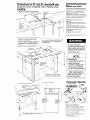
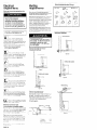
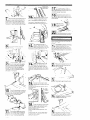
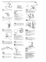
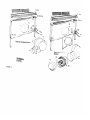
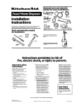
KIVDEIOOTOB
KIVD860TOB
KPED890T
KPID850T
30” and 36”
Downdraft
Vent Systems
30” Plenum
36” Plenum
External Power
Internal Power
The downdraft vent system
can be installed with either
an interior mounted motor
or an exterior mounted blower
IMPORTANT:
Read and save these instructions.
Installer:
Leave Installation Instructions with the
Homeowner.
Homeowner:
Keep Installation Instructions for
luture reference.
Save Installation Instructions for local electrical
inspector’s use
SPECIAL NOTE:
Dimensions and o:her Information given are lor
Installations with any KItchenAid cooktop. If installIng
the downdraft venl system with a different brand of
cooktop, consult that manufacturer’s
cutout dlmenslons
and lnstailatlon methods and the Information in this
guide
a
Interior mounted
motor
Exterior mounted motor
Exterior roof-mounted system requires Roof
Mount Kit, Part No. 4173296, which includes
dome cover and flashing. See your KItchenAid
dealer
CUL
Dimensions for 30” and 36” downdraft vent
systems when installed with a KitchenAid
cooktop:
Before you start...
Proper lnslallatlon
IS the Installer’s
responslblllly.
A quaIlfled technician should ~nslall Ihis downdraft “en!
system Make sura you have everything necessary lor
corred ~nslallal~on II IS Ihe responslblllly 01 Ihe
mstaller lo comply with Ihe installallon clearances
specllled ,n these ~nslrucl~ons.
Built-in cabinet dimensions:
y1”*sn,YI” -
Check locatlon where downdrall venl and cooklop WIII
be inslalled. The local~on should be away from slrong
drall areas, such as windows or doors and strong
healing ven,s or lans.
Eleclrlcal ground
requiremenls
is requred
If cablnel hss a drawer,
removed and Ihe drawer
lronl of cabfnel
Counlerlop
openlna
See Eleclr~cal
Ihe drawer WIII need lo be
lronls lnslalled permanently
dlmenslons
36” base cablnel IS recommended
30’downdrafl
“en,.
42” be% cablnel IS recommended
36- downdrafl “en,
lhal are shown
lor Ihe
lor Ihe
Note: The downdraft
“en, IS located dlrealy
the cookiop lnslall downdraH “en, hrsl
1\l
1;;;,I;
Ordinances’
e
Important:
Observe
lo
behmd
all governing
ALL OPENINGS IN THE WALL OR FLOOR WHERE
THE DOWNDRAFT
VENT IS TO BE INSTALLED
Failure to meet codes and ordinances
could lead to fire or electrical shock
downdraft
Island cabinet dimensions:
30’CtiO”!
Widlh
ZT
vend before using the
NOTE:
It is the customer’s
responsibility
to:
- contact a qualified, electrical
installer.
- assure that electrical
installation is adequate and in
conformance
with National
Electrical Code, ANSVNFPA
70-1987” and local ordinances.
87,v
----------I
FOR YOUR SAFETY:
Special care must be taken when
drilling holes into the wall.
Electrical wires may be
concealed behind wall covering.
Use dimensions
lor vent duct locatlon
lhal apply lo your Inslallatlon.
Diameler
of cut-out will be delermlned
by Inslallallon.
J
I
I
Tools and materials
Downdraft vent dimensions:
Mobile Home Installation
II,
See cooktop Installation lnstructlons
cooktop
I
PANEI-
A
dimensions,
for
I
The mslaHa11on of IhIs downdraH vanI mus! conlorm lo
Ihe Manufactured
Home Conslrucl~on and Salely
Slandarda. TII!B 24 CFR. Parl 3280 (formerly the
Federal Standard for MoblIe Home Conslruct~on a-d
Salely T~!le 24. HUD, parI 280) Four-wre power
supply musl be Jsed and Ihe appliance Waring mu51 Se
,evlsed
See E~eclr~cal reqwemenls
Capes 01 ,hs standards l,sled may be ablalned :‘o-,
** National
Fire Proleclion
Associalion
Ballery March Park
O”,ncy. hlassachusells
02169
Electrical
requirements
Electrical ground is required
appliance.
on this
Electric Shock Hazard.
Improper connection of the
equipment-grounding
conductor
can result In a risk of electrical
shock. Check with a qualified
electrician or service technician if
you are in doubt as to whether the
appliance is properly grounded.
IMPORTANT:
!;a,.
lnstallallon
Recommended
Venting
requirements
Ouchvork
Nine Inch
provided
Inslalled.
mounled
Delermine which venl~ng melhod lo usa Thu leng:h 01
duclwork and number of elbows should be kept 10 a
mmmum lo provide efllcent perlormance
The we of
duclwork should be undorm
Do Nol inslall Iwo elbows
loqelher
Use dud lake lo seal all ,o1n1s or. duel
sykm
Ductwork can extend elth& through wa’~ or
rod Use caulking to seal exierior wall or rcrot open\ng
around cap FIguris l-5 show common wwng
melhods and types of malerials needed
Flexible ductwork 1s Not recommended
If I( 1s used,
calculale each fool 01 llexlble dudwork as Lwo feet of
slralghl metal ductwork.
Flerlble elbows c~unl twce
as much as slandard elbows Use only melal dbclwor
Exterior mounted vent motor
installation
methods
11 II
~nslallat~on IS adoq~ate and 1s in conformance wllh the
Nal~onal Eleclrlca, ‘Code. ANSIINFPA 70-1987”
and
local mdes and or~!,nances
BaHery March Park
Cluincy, Massachussns
Potential Fire Hazard.
Venting system must terminate to
the outside. Do Not terminate the
ductwork in an attic or other
enclosed space. This may result
in a fire hazard.
A 123 in,, 60 Hz, AC only, 15. or 20.
amper?. iused evxlr1c.3 supply 1s required.
DO NOT IUSB the ~leutral (Time-delay fuse or c1rcu0
breaker 1s recommended,
II IS recommended thal a
separale c,rcui, se’v,ng oniy ,h,s appliance be
prov,ded
/c1
DOW:;bHAFT
CONNECTED
Island locallon
Interior mounted vent motor
installation methods
02169
IB.
.
Figure
Island
lnlerior
wall
Code, ANSI/NFPA 70 ,987” and local codes and
o’dlwrces
for Ihe k’lowa!, ral,ng 01 Ihe downdrall ye,,,.
The ser~al~ral~no o,aIe 1s located on Ihe riaht side.
1
This +i, lance should be connecled
lused-i! sconrecl (or circu,, breaker]
Ibroug’l f;ex~ble, ar,nored or nonmelalllc-shealhed.
ccpper cable (wlb grouna ng we)
Allow some
T Ihs cable so Ihe cowndrah vent can be moved
sevclng
is e”el nL:essar,
.
slack
II
Roof
Figure
A U L ited cond”,, conneclor mus, be
.
prov,de> al each end 01 Ihs power supply
cable (al the downdran “en, and a, Ihe unct,on box)
Two U L ~+sled condu:! co,,,,eclors lor 1b e connenions
a’ I’le w~r,ng box ari in Ihe parls package
/G
.
Flgure
4
lo the
box
1F
A WIIII j d,agram ,s located on Ihe ,ns,de of
Ihe co”dr lo Ihe w,r,ng box and on Ihe back
cover o’ these ~mslrucl~ons
venling
2
Recommended duct length for
interior mounted blower
Use 6’duct with a maximum lenglh 01 25 feet lo, dud
syslem
For besl perlormance,
use no more lhan three
90’ elbows. To calculale Ihe length 01 syslem you
need, add the eqwalenl
Ieel for each duel piece used
in Ihe syslem. See Ihe lollowlng example
6” duct system
Electrical connection and
recommended grounding method
Figure
2. Rbn I~BXID,~ armored or nonme,allIc sheathed
copper cable (wllh grounding we) from fused
dlsconnecl c,rcu~l b,eaker or ,uncl,on box lhrauqh Ihe
cabInsI hole lo dounarall
“en, local~on A U L &led
cond”,t conr,eclor musl be ;nslalled a, each end of Ihe
cower supply cable ,a, :he downdraH venl and a, Ihe
,unc,.on tmxj
2 90. elbows
1 wali cap
8 !eel slra,gh,
Length o’ 6’syslem
PANEL B
3
locallon
VENT MUST BE
WITH COPPER WIRE
1E
fittings
needed lor lnslallallon
Is nol Included.
round, In-line backdraft
damper Is
wllh exlerlor mounted motor and must be
Wall cap Is provided wllh lnlerlor
motor.
Use onlv melal ductwork
lnsirucllons
standard
= ‘8 ,I
5
location
Recommended duct length for exterior
mounted blower
Use 9’ duct wflh a ma,mum
lenglh 01 55 feel lor dun
system For best pedormance use no more lhan IIYB
900 elbaws
To calculate the lengt of system you need, add Ihe
eqwa:enl
lee1 for exh duel p,ece used ,n Ihe system
See Ihe Mxwng
ex,ir-pie
h!axlmum
i
2
i
10
lenglh
tlanS,,,on
900 elbow
wall cap
IeeL slralghl
Length 01 9’ syslem
PANFI
r:
-
.
I
Bud when vxlalled I” Ihe cablnel Place Ihe motor 0’1
Ihe blower box so that Ihe duel opsn,ng IS ,n ,t,s
psflion you need lo complele the ductwork
assemble lhs downdralt vent system
Remove downdran blower box and molci
section lrom cartons. Remove any shIppIng maler8als,
lape and prolecl~ve Mm from downdratt blower box and
molar Remove parts package from lnstds blower box
opening Remove capac~lor from motor.
9” duct system
Recommended
Now start...
I Interior located blower
standard
fittinqs
= 55 Ieel
Use all four nuls lo allach Ihe motor 10
Ihe blower bx. Use a IOmm or 318’ ralchat
= OH
= 1otl
- OH
-1Oh
= 20 fi
Remove Ihe 4 screws (2 each side) Iha!
secure Ihe vent cover assembly
Place
strews and cover assembly in a 5~118pI&e
117
(18
Turn pawer supp,y on Check
opera,,“”
01 Ihe blower, spead
and ndfcalor l,ghl If one doss
opeiale, disconnec! power source and checm
connections have been made c”rred,y
.
,,e
conl’”
no,
lhal WIIB
Conned 6’ dudwork lo blower due!
P”s111on ductwork lo avoid wal, s,u”s
and floor jousts Complele all duc!worK
Use duel lape to seal all ,“,nts Ductwork rnus, end WI!.,
a wall or rwf cap
-a
.
Rerove
Ihe Iwo condull
mnnectors
lrom Ihe
Tlghlen Ihe’l”&g
r,ngs Loosen screws on Ihe lop
condull c”nnen”r
Thread w,rws lrom motor conduit
through cnndult t”nneclor
and through Ihe open,ng of
the wnng box Tlghlen Ihe cnndun c”nnecLors SC~QWS
holes (two on lop and two on each
side). Llfl the downdraft wnl sllghlly and carel~lly
move to Iron1 01 culout Drill holes “s,ng llB’dr,Il bit
n you cannot drill through Ihe top surface 01 ,hw
cnunlertop malerlal, us.8 JW Ihe two side mouwng
poSlll”“S
l!-E!!l
.
SC~QWSremoved
in
3
PJ!!L
Exterior
l~S,r”~,~“ns
pr”v,ded
located
blower -
Exlerlor roof-mounted
Kil, Part No. 4173296.
LIII Ihe downdrah “en, back I”,”
pxlll””
Use IWO mo”nllng SCIQWS lo
swcure Ihe downdrafl vwnl lhrough Ihe
lop01 Ihe munlertop
(one on each sldo)
H you are only us,ng Ihe Iwo side m”un,,ng s”ews
tnserl scrwws but Do Nol llghlen at IhIs l,me
Thread Ihe two, brown wires Wh spade
lermlnals lhrouah Ihe rubber ca” of the ca”acfloi
Allach one we-(” one of Ihe &de. cap&nor
leim~nals. Then allach the other we lo Ihe other
nstde, capacitor terminal.
Replace Ihe rubber cap
over Ihe lop of Ihe caputor.
Put Ihe capac,lor ,n,” Ihe
lower sed~on 01 .he w,~ng box
syslem
w,h the cooklop
requires
I
Roof Mounl
31
Place cardboard 01 olher form o’ prolec\‘“n
on lop 01 a llal surlace where you can easily
assemble Ihe downdrah vwnl syslem
.
Remove downdrah blower box and molar
s@d~on from caflons Remove any shlpplng malw’ials
lape and proleclIve film from oowndrall blower box and
molar Remove pals package lrom inside blower wx
operxng,
Remove Ihe 4 screws (2 on each side) tha!
swcurw Ihe “en, mver Place screws and
COYel in a safe place.
screws lhal w~ii attach legs lo cabinet. Sew:
legs IO
cabinet floor Check aga,n lhat blower houslrg IS level
Tighlen the screws ihal attach the legs l” the “lower
box
Remove the lour nbls from one b:oaer “ox
“s,ng a IOmm or 98’ nut dwer or ratchel
Use IWO mo”nll”g
scrwws 10 Sec”1Q
downdrah vanI lo Ihe stdes 01 c”unler!“p
C”l”“l
If Ihe side mounting screws were inserted
tIghten screws now
h
I” Step ‘3,
110
Use a PhIllIps screwdwer
l” remove the
screws thal attach the legs l” Ihe blower
box Place the slolled area of legs over
the area where the screw opemngs are localed
Replace screfis bul Do No, llghlen screws
.
Place adapter plate and 9’ ro’Jnd lake-on on
Ihe blower box. Use all four nuts lo attach
Ihe adapler lo Ihe blower box
Loosen
Ibe
screws
116
- 1
on i,w lower condull
connecloi
Thread Ihe cave supply
1 cable lhrough Ihe condull m~;lwcl”r
T\ghlen Ihe screws on Ihe mndult conneclo’
oisconnecl
power supply.
Connec, Ihe Ihww. ,vh,le w,res iogelher wllh a W118
mnneclol
.
l::sert downdraft blower box and mo,“,
I?!” counlenop cut”“,
Two people are
recommended
lo support Ihe welghlol
the aowndra’l ien; dkr,ng I’IIlng Posn~on downdrah
ibr’ so I, 8s ~,I.~“c’Qo n ~u\o”I aid parallwl w,,h the
Use a PhIllIps screwdr
scrwws thal allach Ihe legs l” t
box Place Ihe slolled area 01 legs over Ihe area v.ri’re
the screw opemngs are localed Reolace sc’ews “1’
Do No! ,,ghlen screws
Wiring belween motor and blower box
iS not provided.
I
I
supply mnnec,,on
connector.
Thread wares lrom motor
conduil lhrough condull connector and lhrough !he
o~en~“q of Ihe WI~I”~ box Tlahte” Ihe conduit
Co”“BctOl screws lo-secure the condull lo Ihe blovier
houslng
at llle lop
Wall Installations
. Use caulking
and wall
compound
belwee”
mou”:,r”;
ilar:-
Roof lnstallatlons
. Follow standard roof,“g procedures
The llashlng sheet should be Bnlered over 1’1s
oper.~“g I” Ihe roof
The lower edge o: Ihe flash’ng should IIB on lop ‘oi
tile shingles and Ihe upper edge should be
uldernealh
Ihe sh,ng,es
Seal Ihe assembly belwee” rhe rool la” a?d lla 71”;
KII~ rooltng mask lo prevenl ieaks
Connect Ihe red we lrom the mo!or 10
Ihe red wre from !he switch us,“g a
.
113
Connect 9’ ouctwork 10 blower due
PoWon ductwork ,o avo,d wall slrds
and lloor jo1s1s Complele all ductwork.
Use duct tape lo seal all ,o~“ls Ven~cal
ductwork lor wall mounled ~nslallal,ons should p,,ch
down sl~ghlly loward the venl lo allow mo~sl”~ lo run lo
ouls,de
m
Lilt 11,~ asn~drsll
van, back ,“,o pos,,,o?
Use !WL mo”n!,“g screws lo seclire Ihe
downcra!r “en, through the Iop 01 Ihe
counlerlop (one on each side) If you are
only “song Ihe t&o s,de mou”:,“g screws, wsel? sc:ews
But Do Nol ughlen a, Ims t,me
.
r
,“\,-;
;/Q
I
120
Tlghlen
/14
Connect Ihe green. grounding wire of Ihe motor w r,ng
cable lo Ihe grounding connecl~o” sc,ew Place w,res
under clip lo preven, hilling Ihs motor cooling b,aee
Place a level aga,“st Ihe lace 01 Ihe blower
box Lswer legs 10 lloor of cablnet
Adjust
pos~!~o” oi legs ~“111blower housing 18 level
Mark and drill s,all,“g holes for screws lhat VIII auach
legs lo cabInal
Secure legs lo cablnel lloor Check
aga~n lhat blower housing 1s level Tlghle” Ihe screws
lhat aitach the lqs lo Ihe blower box
Run motor wlnng lhrough
access area lo the w,r,“g
blower box
on ,he lower conad,,
Ihe power suppiy
condull mnneclor
co”“exor
Disconnect
power supply.
Conned the lhree, while w,res logelher
conneclol
7
,
Loose” Ihe screws
conneclor
Thread
cable through Ihe
the screws on Ihe condull
.
Remove Ihe dome lop Loose” Ihe
,
~,‘a,” relic1 screws Thread Ihe
molar w,nng through the strain
reltel. Tlghlen Ihe screws on the slra” rel~el
Conneci Ihe while and black w,res 01 Ihe motor n’:,“g
cable lo Ihe while and black leads of Ihe motor wI,h
IWIS-on wre mnneclors.
El
-I
w,,h a w,re
Connect Ihe three, green, grou”d,“g
w,res logelher
wllh a w!re connector
Connect Ihe IWO t,lacn w,:es
together wllh a w\re connector
Replace wlrlng box cower
j211
Turn power supply on Cleck the
operal~on of Ihe blower, bpeed conlro:
and lndlcalor llghl ti one does not
opsrale, dlswnnecl
power source and check lhal w,re
mnnecl~on~ have bee” made cone+.
.
Ine dLc.1
box on !ye
For wall-mounted
installations,
rep ace the
dome top lo cover Ihe molar and
mnne*,ons.
Roof lnslallallons
requ,re a
roof cap lo be used I” place 01 Ihe come
e four
COYal “sing
screws removed I”
Instail cooklop arxord~na 13 ,“s,a!Ie’,zn
~“slr~cl~ons prov,ded WI h :he co&o;,
D!i
.
Lse lMi0 moLnl,ng screws ;o secure
cowndran “en! to ,ne sides 01
counterlop c”:wI
If the side moun,,“g screws v,ere
lKse”*o 11 S!ep 8 !Igh!er screws now
ml
PANEL
.
E
Uelemne
the localion where Ihe
dx~erior blower assembly ~111be
nslalled
Cul a 10’ diameter hole
1 !he wall or roe,
El
.
Remove tile wlr,“g box cover screw
Place co”er and screw I” a safe zlace
Pull ,wres tlrough ope”,rg
To get the most efficient use
from your new downdraft vent,
read the Use and Care
Information
section on the
back cover. Keep Installation
Instructions
and Use and Care
Guide close by for easy
reference.
lnkrior
located blower
Numbers
correspond
to steps
PANEL C
If downdraft vent
does not operate...
Use and Care
Information
First, check that clrcult breaker is not tripped or fuse
blown. A Waring diagram is located on the insIde cover
of the wiring box Read before servicing
The Downdraft Venting System IS designed to remove
smoke, cooking vapor and odors from Ihe cooktop
area. For the besl results. the vent should be operatlng
before cooking is started. If you use large or tall
utensil2 place them on the large rear element or burner
surface
If you need
assistance...
When you cal, you need the downdraft venl model
number and serlal number. Bolh numbers can be
found on the serlalirating plate in the lower right corner
01 the blower 130x
To Operate the DowndraH Vent: Lift the top cover of
the vent. Turn Ihe switch lo a setting that will provide
Ihe amount of venting that you will need. The switch
has InfInIte settings. The indicator light should be on
Place cooking ulensll on the surlace unit. When
cooklng IS completed, lurn Ihe surface unrt off, remove
the cooklng utensil and turn the downdraft venl
switch off.
It is recommended
lhat the fronl cover to the vent be
The front cover opens to
kept closed during cookIng
access the filters for cleaning.
KitchenAid@
LENGTH
OF WARRANTY:
KITCHENAID
One Year Full Warranty
from dale of Installation.
Five Year Llmrted Warranty
one year ful plus second through fifth
year limited from date of inslallatlon.
KitchenAid,
Incidental
O’
Downdraft
DO Not use the downdraft
not in place.
vent if the filters
Clean the outside suiiace of the downdraft vent with
soap and water. Do Not use scouring powder or
abrasive solutions.
A Clean-out Trap at the bottom of the blower box IS
provided to help you retrieve any objects thal might
have lallen into the downdraff vent. Turn downdraft
vent switch OH. Remove two wing nuts and the aver to
the trap Remove the object. Replace the cover and the
two VAng nuts.
The clean-out trap should b-e removed and the area
cleaned wrth a hot detergent solution at least twice per
year. Clean the trap area if any spills into the vent
have occurred.
KITCHENAID
WILL NOT PAY FOR:
Replacement parts and repair labor to correct defects
in materials or workmanshlp.
Service must be provided
by an authorized KItchenAId servicing outlet
A. Service calls to:
1. Correct the Installation of the downdraft vent.
2. Instruct you how to use the downdraft vent.
3 Replace house fuses or correct house wiring.
Replacement
workmanshlp.
B. Repairs when downdraft vent is used in other than
normal home use.
C. Damage resuklng from accident, afteration.
misuse, abuse, improper installation or installation
not I” accordance with local electrical codes.
D. Any labor costs during limited warranty.
E. Replacement parts or repair labor costs for unrts
operated outslde the United States.
F. Pick up and delivery. This product IS deslgned lo
be repalred in the home.
motor If defective
in materials
or
Some slates do not allow the exclusion
or limitation
grves you specific legal rights and you may also have other rights which vary from slate to stale
How to arrange for service.
. FIrsI call you dealer or repalr service he recommends.
* All sewice should be handled locally by the dealer from whom you purchased the un11or an authorized KItchenAId servlclng outlet. If your local service
Jnsatlsfactory.
contact the Customer Relations Department, KitchenAld, Inc , P.O. Box 558. St. Joseph, Ml 49085-0558.
Call Toll Free 800-422-1230.
Parl No. 3177298 Rev A
1 C',s@ KII~~G rA,d 11.c
are
Vent Warranty
WILL PAY FOR:
Inc. does not assume any responsibility
for incidental
or consequential
damages.
or mnsequentlal
damages, so this exclusion or IImItation may not apply to you.
This warranty
Cleanina: The fillers inslde the loo of the downdraft
vent should be removed and cleaned frequently. The
filters can be olaced in the dishwasher or cleaned in a
hot detergent’solution.
Keeping the lifters clean will
Improve Ihe operallng efficiency of the downdraft vent
system.
Prepared
by KiIchenAld’h
St Joseph,
hl~ch~gan 49085
is
PrInted II- U.S.A