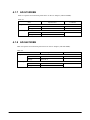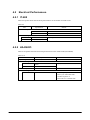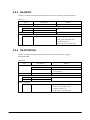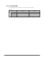
1
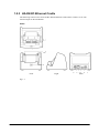
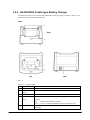
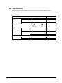
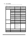
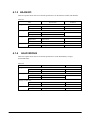
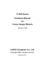
IT-600 Series
Hardware Manual
for
Linear Imager Models
(Version 1.00)
CASIO Computer Co., Ltd.
Copyright ©2007. All rights reserved.
September 2007
Table of the Contents
1.
1.1
1.2
1.3
1.4
1.5
1.5.1
1.5.2
1.5.3
1.5.4
1.5.5
1.5.6
1.6
2.
2.1
2.2
2.3
2.4
2.5
2.6
2.7
2.8
2.9
3.
4.
4.1
4.1.1
4.1.2
4.1.3
4.1.4
4.1.5
4.1.6
4.1.7
4.1.8
4.2
4.2.1
4.2.2
4.2.3
4.2.4
4.2.5
4.2.6
4.2.7
4.2.8
Editorial Record
Preface
Overview of the Products
Features
Available Models
Options
Accessories
External Views
IT-600
HA-D60IO USB Cradle
HA-D62IO Ethernet Cradle
HA-D30CHG Cradle-type Battery Charger
HA-D32DCHG Dual Battery Charger
HA-D94CFU2 CF Card Extension Unit
Device Configuration Diagram
Hardware Specifications
IT-600
HA-D60IO
HA-D62IO
HA-D32DCHG
HA-D30CHG
AD-S15050BE
AD-S42120BE
HA-D20BAT, HA-D21LBAT
HA-D94CFU2
Product Identification and Reference Numbers
Quality References
Environmental Performances
IT-600
HA-D60IO
HA-D62IO
HA-D32DCHG
HA-D30CHG
HA-D94CFU2
AD-S15050BE
AD-S42120BE
Electrical Performances
IT-600
HA-D60IO
HA-D62IO
HA-D32DCHG
HA-D30CHG
HA-D94CFU2
AD-S15050BE
AD-S42120BE
2
4
5
6
6
7
8
9
10
10
12
14
17
16
18
19
20
20
23
25
27
28
29
30
31
31
32
33
33
33
33
34
34
35
35
36
36
37
37
37
38
38
39
39
39
40
4.3
4.3.1
4.3.2
4.3.3
4.3.4
4.3.5
4.3.6
4.3.7
4.3.8
4.4
4.4.1
4.4.2
4.4.3
4.4.4
4.4.5
4.4.6
4.4.7
4.4.8
4.5
4.5.1
4.5.2
4.5.3
4.5.4
4.5.5
4.5.6
4.5.7
4.5.8
Mechanical Performances
IT-600
HA-D60IO
HA-D62IO
HA-D32DCHG
HA-D30CHG
HA-D94CFU2
AD-S15050BE
AD-S42120BE
Reliability
IT-600
HA-D60IO
HA-D62IO
HA-D32DCHG
HA-D30CHG
HA-D94CFU2
AD-S15050BE
AD-S42120BE
Compliance
IT-600
HA-D60IO
HA-D62IO
HA-D32DCHG
HA-D30CHG
HA-D94CFU2
AD-S15050BE
AD-S42120BE
41
41
41
42
42
43
43
44
44
45
45
46
46
46
47
47
47
47
48
48
48
48
49
49
49
49
50
No part of this document may be produced or transmitted in any form or by any means, electronic
or mechanical, for any purpose, without the express written permission of CASIO Computer Co.,
Ltd. in Tokyo Japan. Information in this document is subject to change without advance notice.
CASIO Computer Co., Ltd. makes no representations or warranties with respect to the contents or
use of this manual and specifically disclaims any express or implied warranties of merchantability
or fitness for any particular purpose.
© 2007 CASIO Computer Co., Ltd. All rights reserved.
3
Editorial Record
Manual
Version no.
1.00
Date edited
Page
Content
September 2007
Original version
4
Preface
This reference manual clearly and concisely sets out the information developers need to know about
the hardware features and detailed specifications on the CASIO IT-600 series with the Linear
Imager integrated (hereafter referred to as “IT-600” in this reference manual unless otherwise noted),
both developed for the destinations of the USA and Canada.
A newest PDA-style industrial data terminal available in two models, IT-600M30U and
IT-600M30UC, offers the IP54 level of dust and water-splash proof compliant with the IEC60529
International standard, and the shock resistance to withstand a fall from a height of up to 1.2 meters
(or 3.9 ft.). The pocket-sized and portable IT-600 comes with various noteworthy features including
the following.
•
•
•
•
•
•
•
•
Built-in high performance imager capable of reading industry standard bar code symbologies
Wireless communications via Bluetooth®
Rugged casing to allow use in extreme environments
Original CASIO digital technology enables capturing of images in all light conditions.
Microsoft® Windows® CE 5.0 offers reliable and real time capabilities.
Superb quality VGA resolution color screen
miniSD card slot for extra storage
AC Adaptors dedicated to IT-600 are designed and built to meet the California’s latest energy
efficiency standards.
5
1. Overview of the Products
1.1
Features
Supporting the outstanding development environment
• Windows®CE 5.0 as the built-in OS
• Visual Studio .NET 2003 (Windows®CE .NET Utilities v 1.1 for Visual Studio .NET 2003)
• Visual Studio .NET 2005
• eMbedded Visual C++ 4.0
Compatibility to various communication systems
• High speed infrared communication with IrDA Ver1.3
• Bluetooth® Version 1.2
• Serial interface with USB version 1.1 (Host/Client)
Small size, light weight (improved portability)
• Dimensions: Approx. 82 (W) x 166 (D) x 27 (H) mm or
Approx. 6.5 (D) x 3.2 (W) x 1.1 (H) inch
• Weight:
Approx. 290 g (including standard battery pack) or
Approx. 10.2 oz. (including standard battery pack)
Improved resistance to environment
• Resistance to fall impact: up to 1.2 m (or 3.9 ft.) in height
• Dust/Water-splash proof : IP54 level (compliant with IEC60529 International Standard)
Capable of scanning industrial standard bar code symbologies
• Readable bar code symbologies : UPC-A, UPC-E, EAN8, EAN13, Codabar (NW-7), Code39,
Interleaved 2of5 (ITF), MSI, Industrial 2of5, Code93,
Code128(EAN128), IATA, RSS-14, RSS Limited, RSS
Expanded, RSS-14 Stacked, RSS Expanded Stacked
Outstanding performance/Large memory
• High-performance CPU
Marvell® PXA270 Application Processor (run at max. 520
MHz)
• Large-capacity memory
RAM
: 64 MB
F-ROM : 128 MB (user area; approximately 60 MB)
6
1.2
Available Models
Table 1.1
Model no.
Linear
Imager
IT-600M30U
IT-600M30UC
Yes
Yes
Memory
RAM
64 MB
64 MB
FROM
128 MB
128 MB
7
Color touch
panel display
Digital
camera
Bluetooth
module
Yes
Yes
No
Yes
Yes
Yes
1.3
Options
Table 1.2 shows the dedicated options available for the IT-600 series.
Table 1.2
Product
Cradle
Battery pack
Battery charger
CF Card Extension
Unit
AC adaptor
Model No.
HA-D60IO
HA-D62IO
HA-D20BAT
HA-D21LBAT
HA-D30CHG
HA-D32DCHG
HA-D94CFU2
Description
USB Cradle (with Host/Client)
Ethernet Cradle
Lithium-ion battery pack (1,850 mAH)
Large-capacity lithium-ion battery pack (3,700 mAH)
Cradle-type Charger
Dual Battery Charger
For CF memory card on the back of the IT-600
AD-S42120BE
DC12V, 3.5A. For HA-D60IO, HA-D62IO, and
HA-D32DCHG. Input from 100 to 240VAC. See note.
DC5V, 3A. For HA-D30CHG. Input 100 to 240VAC
(with US power cord). See note.
USB cable for cradle, cable length 2.0 m
Hand belt to hold the IT-600
AD-S15050BE
Cable
Hand Belt
DT-380USB
HA-D95HB2
Note:
The AC adaptor is in compliance with California’s Appliance Efficiency Regulations (Title 20,
Division 2, Chapter 4, Article 4, Sections 1601 to 1608).
8
1.4
Accessories
The following accessories are accompanied in each individual carton box of IT-600 series.
Table 1.3
Accessory
User’s guide
Stylus
Large-capacity battery pack cover
Neck strap
Touch screen protect sheet
Q’ty
1
1
1
1
1
Remark
In English
Required when HA-D21LBAT is installed.
9
1.5
External Views
1.5.1 IT-600
18
Left
Right
Front
Fig 1.1
See Table 1.4 for the descriptions for each referenced part on the terminal.
10
Rear
Table 1.4
Names of parts
No.
1
2
Name
Buzzer
Indicator 1
3
Indicator 2
4
5
Power Key
Touch Screen
6
7
Center Trigger Key
Execute Key
8
9
Text Key
Fn Key
10
11
12
CLR Key
Numeric Keys
Cursor Key
13
14
Microphone
Speaker
15
16
17
18
19
20
Trigger R Key
Trigger L Key
Headset Jack
Reader Port
IR Port
Power
Supply/Charge
Terminals
Digital Camera
LED Light
Strap Holes
Extension Port
Reset Switch
miniSD Card Slot
Battery Pack Cover
Battery Pack Cover
Lock Switch
Cradle Mount Holes
21
22
23,24
25
26
27
28
29
30
Description
Sounds a buzzer.
Orange
: Charging the battery pack.
Green
: Charging the battery pack complete.
Red
: Battery pack is abnormal or the surrounding temperature is out
of the range.
Flashes in blue when operating via Bluetooth. Lights in green when reading
a bar code successfully or in red when alarming (programmable).
Turns the power on and off.
Displays text and operating instructions. Also used to operate the Handheld
Terminal and enter data using stylus provided.
Used to perform bar code reading. Can be assigned an arbitrary function.
Press when finishing entering numerical values or when moving to the next
step.
Press when switching to the text input mode.
Used to make various settings in combination with the numeric keys or
when starting a pre-registered application.
Used to clear one letter to the left of the input key.
Used to enter numbers or letters.
Perform the same functions as up, down, left and right arrow keys on PC
keyboard.
Used to input a sound including voice.
Alarms and voice messages are output here. Voice messages are not output
from the speaker when a headset is connected to the headset jack. (The
sound of camera shutter is always output from the speaker.)
Used to perform bar code reading.
Used to perform bar code reading.
A separately sold headset can be connected here.
Emits an LED light that reads bar codes.
Used for communication with another Handheld Terminal.
Used to supply power to the Handheld Terminal and to charge the battery
pack from Cradle and Cradle-type Charger.
Used to capture photographs, images.
Used to light up an object when capturing with the digital camera.
Used to attach the strap.
Provided for future extension.
Used to reset the terminal.
Provided for installing a miniSD card by removing the battery pack.
Used to cover the battery compartment that holds the battery inside.
Used to lock the battery cover and to release.
Used to mount the Handheld Terminal to separately sold cradle.
11
1.5.2 HA-D60IO USB Cradle
The following external views show the HA-D60IO USB Cradle. Refer to Table 1.5 for each
referenced part on the HA-D60IO.
Views
8
Front
7
5
6
4
Top
3
Rear
Fig 1.2
12
2
1
Table 1.5
Names of parts
No.
1
Name
USB Client Port
2
3
4
USB Host Port
Selector Switch
AC Adaptor
Jack
Terminal Detect
Switch
Power Contacts
Power Indicator
Lamp
5
6
7
8
Mount Hooks
Description
Used to transfer system data and file data (download, upload) by connecting the
Cradle to a PC using a USB cable (DT-380USB). A dedicated driver must be
installed in the PC before connecting the Cradle to the PC.
Used to connect a corresponding USB peripheral device.
Used to switch between the USB host port and USB client port.
Connect the dedicated AC adaptor (AD-S42120BE) here.
This switch detects terminal when it is mounted correctly in the Cradle.
Power is supplied to the terminal via these contacts.
This lamp indicates the power status and the mounting status of the Handheld
Terminal.
Off
: Handheld Terminal is mounted.
Green : Power on and the Handheld Terminal is mounted correctly.
These hooks are used to stabilize the terminal when mounting it on the cradle.
13
1.5.3 HA-D62IO Ethernet Cradle
The following external views show the HA-D62IO Ethernet Cradle. Refer to Table 1.6 for each
referenced part on the HA-D62IO.
Views
7
8
Top
10
9
Front
Right
Fig 1.3
14
6
5 4 3 2
Back
1
Table 1.6
Names of parts
No.
1
Name
USB Client Port
2
3
Selector Switch
LAN
Connection
Status LED
4
LAN
Communication
Status LED
5
LAN Port
6
AC Adaptor
Jack
Terminal Detect
Switch
Ethernet Cradle
Contacts
Power Indicator
LED
7
8
9
10
Mount Hooks
Description
This port is used to transfer system data and file data (download, upload) by
connecting the Ethernet cradle to a PC using a USB cable (DT-380USB). A
dedicated driver must be installed in the PC before connecting the Ethernet
cradle to the PC.
This switch is used to switch between a USB connection and a LAN connection.
This LED shows the status of the LAN connection.
Off
: LAN cable not connected correctly.
Lit Green
: LAN cable connected correctly.
This LED shows the LAN operation status.
Off
: No communication.
Blinking Green
: Communication in progress.
This port is used for connecting the cradle to a computer or hub over a LAN
cable so that system data and file data can be transferred (uploaded or
downloaded). Special driver software must be installed in the IT-600.
Connect the dedicated AC adaptor (AD-S42120BE) here.
This switch detects terminal when it is mounted correctly in the Cradle.
Power is supplied to the IT-600 via these contacts.
This LED indicates the power status and the mounting status of the IT-600.
Off
: IT-600 is not installed. Or, the AC adaptor is not connected.
Green : Ethernet cradle turned on, and IT-600 correctly set in the cradle.
Use these hooks to lock the IT-600 into the Ethernet cradle.
15
1.5.4 HA-D30CHG Cradle-type Battery Charger
The following external views show the HA-D30CHG Cradle-type Charger. Refer to Table 1.7 for
each referenced part on the HA-D30CHG.
Views
5
Front
4
3
2
1
Top
Rear
Fig 1.4
Table 1.7
No.
1
2
3
4
5
Names of parts
Name
AC Adaptor Jack
Terminal Detect
Switch
Power Contacts
Power Indicator
Lamp
Mount Hooks
Description
Connect the AC adaptor (AD-S15050BE) here.
This switch detects terminal when it is mounted correctly in the charger.
Power is supplied to the Handheld Terminal via these contacts.
This lamp indicates the power status and the mounting status of the Handheld
Terminal.
Off
: Handheld Terminal is not mounted.
Green : Power is on and the Handheld Terminal is mounted correctly.
These hooks are used to stabilize the Handheld Terminal when mounting it on
the charger.
16
1.5.5 HA-D32DCHG Dual Battery Charger
The following external views show the HA-D32DCHG Dual Battery Charger. Refer to Table 1.8
for each referenced part on the HA-D32DCHG.
Views
Right
Top
Left
2
3
1
3
Bottom
4
Fig 1.5
Table 1.8
No.
1
2
3
4
Names of parts
Name
Charge indicator
lamps
AC adaptor jack
Dual battery charger
connection port
Connection bracket
attachment holes
Description
These lamps indicate the charge status of each battery pack.
Off
: Not charging
Red
: Charging
Red Flashing : Battery pack problem
Green
: Charging complete
Used to connect the dedicated AC adaptor (AD-S42120BE) here.
Used to connect another Dual Battery Charger at side.
The connection bracket attaches here when you connect another Dual
Battery Charger.
17
1.5.6 HA-D94CFU2 CF Card Extension Unit
The following external views show the HA-D94CFU2 CF Card Extension Unit and its cover.
Views
CF Card Extension Unit
Cover
Fig 1.6
18
1.6
Device Configuration Diagram
IT-600
Products with
IrDA
IrDA Printer
IT-600
PC
IrDA Port
(IrDA1.3)
Products with Bluetooth
Bluetooth Module
(Ver. 1.2 Class 2)
Bluetooth Access-Point
Pocket Printer
Bluetooth Headset
Earphone /
Headset with call-in control
Microphone
Mini SD Memory
SD I/F
USB Cradle
HA-D60IO
USB Port
Ethernet Cradle
HA-D62IO
(Host / Client)
USB Host
Wired Modem / LAN
USB Client
PC
AD-S42120BE
Power Supply
Terminals
(Built-in Charge
Circuit)
HA-D30CHG
AD-S15050BE
HA-94CFU2
Extension Port
Battery Terminals
HA-D20BAT / HA-D21LBAT
HA-D21LBAT
HA-D21LBAT
HA-D21LBAT
HA-D20BAT
HA-D20BAT
HA-D20BAT
HA-D32DCHG
HA-D32DCHG
AD-S42120BE
Fig 1.7
19
HA-D32DCHG
2. Hardware Specifications
2.1
IT-600
Tables 2.1 and 2.2 explain about the hardware specifications of IT-600 series including
IT-600M30U and IT-600M30UC.
Table 2.1
Item
Specification
Remark
CPU, Memory
CPU
Marvell® PXA270 Application Processor
Operating clock; max 520
MHz
RAM
64 MB
FROM
128 MB (user area; approx. 60 MB)
Linear Imager
Type
CMOS bi-linear image sensor
Wave length
617 nm
No. of scans
200 per second or faster (automatic adjustment)
Resolution
0.127 mm
PCS
0.25 or more
Readable distance
Approx. 60 to 300 mm
Readable width
Max. 46 mm
When the readable distance is
at 60 mm.
Max. 200 mm
When the readable distance is
at 300 mm.
Daylight for scanning
50,000 Lux or less
Readable 1D bar code
UPC-A, UPC-E, EAN8, EAN13, Codabar(NW-7),
symbologies
Code39, Interleaved 2of5 (ITF), MSI, Industrial
2of5, Code93, Code128, (EAN128), IATA,
RSS-14, RSS Limited, RSS Expanded, RSS-14
Stacked, RSS Expanded Stacked
Vibrator
Yes (for indications of scanning completion, VoIp
call-in)
Display
Display device
3.7-inch transflective TFT color LCD
No. of dots
480 (horizontal) x 640 (vertical)
Dot pitch
0.117 (horizontal) x 0.117 (vertical) mm
Gradation
65,536 colors
Display font
Scalable font
Backlight
LED
Indicator
LED
2 pcs (in 3 colors)
Left: battery charge status
Right: programmable
Continue.
20
Input
Keyboard
Numeric (Alphabet) keys, CLR key, Execute key,
Fn key, Text key, Cursor key
Control keys
Power ON/OFF key, Reset switch
Trigger keys
Trigger R key, Trigger L key, Center trigger key
Touch panel
Yes
Infrared interface
Standard
IrDA ver.1.3 compatible
Communication process
Half duplex
Synchronization
Start and stop bits, frame method
Baud rate (in bps)
9600, 19200, 38400, 57600, 115200, 4M
Comm. range
0 (contact) to 0.3 m
Bluetooth
Standard
Bluetooth® Specification Ver.1.2
Comm. range
Approx. 3 m
Output power
Max. 3 dBm ( PowerClass 2)
Vary depending on the
environment
USB
Host
Baud rate
Full speed (12 Mbps)
Low speed (1.5 Mbps)
Power to an
5V±5% (maximum 500 mA)
See note on page 22.
external
device
Client
Baud rate
Extension port
Connector for HA-D94CFU2
SD card slot
Terminals
miniSD memory card
In the battery compartment.
Layout
for USB
Cradle
Full speed (12 Mbps)
1
Description
2
3
4
5
6
7
See Table 2.2
Headset jack
4 poles in rounded shape
Speaker
Monaural
Microphone
Monaural
Digital camera (IT-600M30UC)
Number of pixels
Approx. 1,000,000 pixels
Device
1/4.5-type CCD color
Aperture
F3.5/F7.0 (2 steps switchover)
Focal distance
f = 3.29 mm (fixed)
Image capture range
30 cm to ∞
LED light
Brightness
3300 mcd
Power
Operation
Lithium-ion battery pack (HA-D20BAT or
Memory backup
Lithium battery (rechargeable) on board
Battery capacity
1,850 mAH (HA-D20BAT)
HA-D21LBAT)
3,700 mAH (HA-D21LBAT)
Continue.
21
Operating period
Approx. 11 hours (with HA-D20BAT)*
*; based on the ratio of cyclic
Approx. 22 hours (with HA-D21LBAT)*
operation of
“Standby:Calculation:Scan” at
20:1:1 when the CPU speed is set
to auto power save mode and the
backlight is turned off.
Memory backup period
RAM : Approx. 10 minutes,
- Lithium battery pack is fully
Built-in clock : Approx. 72 hours
charged.
- At room temperature.
Battery pack charge
Approx. 4 hours for HA-D20BAT
period
Approx. 7 hours for HA-D21LBAT
- The power on the IT-600
terminal is turned off.
- At room temperature
- The dedicated AC adaptor is
used to power the IT-600
terminal via battery charger or
cradle.
Memory backup battery
Approx. 4 days
- Time period until when the
charge period
battery is fully charged.
- Battery pack is being installed.
- At room temperature.
Memory backup battery
10 mAh
rated capacity
Method to charge
Power supply by cradle
Yes
memory backup battery
By battery pack (when terminal’s
Yes
power on )
By battery pack (when terminal’s
Yes
power off)
Dimensions and weight
Dimensions
Approx. 166 (D) x 82 (W) x 27 (H) mm
Approx. 6.5 (D) x 3.2 (W) x 1.1 (H) inch.
Weight
Approx. 290 g (or approx. 10.2 oz.)
Including standard battery
pack installed.
• Terminal layout and the description for the SD Card slot
Table 2.2
Terminal no.
1
2
3
4
5
6
7
Signal
V BUS
V CRADLE
D+
NC
USB_ID
DGND
Description
Power from USB cradle
Power supply/Charge to terminal
USB D +
Switch-over between USB host and USB client
USB D GND
Direction
OUT/IN (see note)
IN/OUT
IN
IN/OUT
-
Note:
When the selector switch on the HA-D60IO is set to “USB Host”, this terminal outputs the power
ON/OFF control signal issued by the IT-600 to the cradle. Or, when it is set to “USB Client”, the
terminal is used to input the USB power (V BUS) from the cradle to the IT-600.
22
2.2
HA-D60IO
Tables 2.3 and 2.4, and Fig. 2.1 explain about the hardware specifications of the USB Cradle
(HA-D60IO).
Table 2.3
Item
USB
Specification
Standard
USB Ver.1.1 compatible
Baud rate
Max. 12 Mbps (maximum)
Remark
Connector
1 VBus
2 – Data (D -)
3 + Data (D+)
4 GND
USB connector B type
1 2 3 4
1 VBus
2 – Data (D -)
3 + Data (D+)
USB connector A type
Power
Input voltage
DC 12V ±5%
from
Current consumption
DC12V approx. 1.6A
AC
4 GND
When supplying power and
transmitting data.
adaptor
Plug
Power
USB host
EIAJ RC-5320A type 4
AC adaptor
AD-S42120BE
Standard
USB Ver. 1.1 compatible
Baud rate
12 Mbps (maximum)
Power to
5V±5% maximum 500 mA
1.5 Mbps (minimum)
external device
USB client
Standard
USB Ver. 1.1 compatible
Baud rate
12 Mbps (maximum)
Layout
See Fig 2.1.
Description
See Table 2.4
Charge/Power
Output voltage
DC5V±10%
supply terminals
Output current
2,500 mA (maximum)
Output current
Constant voltage method
Battery charge
Approx. 4 hours for HA-D20BAT
time
Approx. 7 hours for HA-D21LBAT
Dimensions and weight
Weight
Approx. 110 (W) x 106 (D) x 93 (H) mm
Dimensions
Approx. 310 g
23
Center; +
•
Terminal layout
1 2
Fig 2.1
3
4
5
6
• Terminal layout and the description
Table 2.4
Terminal no.
1
2
3
4
5
6
Signal
V BUS
V CRADLE
D+
USB_ID
DGND
Description
Power from USB cradle
Power supply/Charge to IT-600
USB D +
Switch-over between USB host and USB client
USB D GND
Direction
OUT/IN (see note)
IN/OUT
IN
IN/OUT
-
Note:
When the selector switch on the HA-D60IO is set to “USB Host”, this terminal receives the power
ON/OFF control signal issued by the IT-600. Or, when it is set to “USB Client”, the terminal
outputs the USB power (V BUS) to the IT-600.
24
2.3
HA-D62IO
Tables 2.5 and 2.6, and Fig. 2.2 explain about the hardware specifications of the Ethernet Cradle
(HA-D62IO).
Table 2.5
Item
USB
Specification
Standard
USB Ver.1.1 compatible
Baud rate
Max. 12 Mbps (maximum)
Remark
Connector
1 VBus
2 – Data (D -)
3 + Data (D+)
4 GND
USB connector B type
LAN
Communication protocol
IEEE 802.3
Media type
10base-T/100base-TX auto-switched
Power from AC
Input voltage
DC 12V ±5%
adaptor
Current consumption
DC12V approx. 1.6A
When supplying power and
transmitting data.
Power
Plug
EIAJ RC-5320A type 4
Dedicated AC adaptor
AD-S42120BE
USB client
Standard
USB Ver. 1.1 compatible
Baud rate
12 Mbps (maximum)
Layout
See Fig 2.2
Descriptio
See Table 2.6
n
Charge/Po
Output
wer supply
voltage
terminals
Output
DC5V±10%
2,500 mA (maximum)
current
Output
Constant voltage method
current
Battery
Approx. 4 hours for HA-D20BAT
charge
Approx. 7 hours for HA-D21LBAT
time
Dimensions
Approx. 110(W) x 106(D) x 93(H) mm
Weight
Approx. 310 g
25
Center; +
•
Terminal layout
1 2 3
Fig 2.2
4
5
6
• Terminal layout and the description
Table 2.6
Terminal no.
1
2
3
4
5
6
Signal
V BUS
V CRADLE
D+
USB_ID
DGND
Description
Power from USB cradle
Power supply/Charge to IT-600
USB D +
Switch-over between USB host and USB client
USB D GND
Direction
IN/OUT (see note)
IN/OUT
OUT
IN/OUT
-
Note:
When the selector switch on the HA-D62IO is set to “USB Host”, this terminal receives the power
ON/OFF control signal issued by the IT-600. Or, when it is set to “USB Client”, the terminal
outputs the USB power (V BUS) to the IT-600.
26
2.4
HA-D32DCHG
Table 2.7 explains about the hardware specifications of the Dual Battery Charger
(HA-D32DCHG).
Table 2.7
Item
Battery charge
Specification
Remark
Charge method
Constant voltage constant current
Charge period
Approx. 2 hours ( for 1 pc x HA-D20BAT)
At room
Approx. 4 hours (for 1 pc x HA-D21LBAT)
temperature
Approx. 3.5 hours (for 2 pcs x HA-D20BAT)
Approx. 7 hours (for 2 pcs x HA-D21LBAT)
Required power supply
AD-S42120BE (dedicated AC adaptor)
Consumption current
Approx. 0.8 A (with single HA-D32DCHG)
Approx. 2.4 A (with three HA-D32DCHGs
connected.)
Operating temperature
Approx. 0 to 40 ºC
Operating humidity
30 to 80 %RH
No. of the chargers to be connected
3 pcs x HA-D32DCHG (maximum)
Dimensions
Approx. 110 (W) x 104 (D) x 46 (H) mm
Weight
Approx. 195 g
27
2.5
HA-D30CHG
Table 2.8 explains about the hardware specifications of the Cradle-type Battery Charger
(HA-D30CHG).
Table 2.8
Item
Specification
Input from AC
Input voltage
DC 5V±5%
adaptor
Consumption current
DC5V approx. 2.5 A
Remark
Plug
EIAJ RC-5320A type 3
Center pin; +
AC adaptor
AD-S15050BE
Dedicated AC adaptor
Terminal layout
Power supply
GND
Power
Output voltage
DC5V±10%
supply/Charge
Output current
2,500 mA (maximum)
Charge method
Constant voltage
Charge period
Approx. 4 hours for HA-D20BAT
Approx. 7 hours for HA-D21LBAT
Dimensions and weight
Dimensions
Approx. 110 (W) x 106 (D) x 93 H) mm
Weight
Approx. 290 g
28
2.6
AD-S15050BE
Table 2.9 explains the hardware specifications of the AC Adaptor (AD-S15050BE).
Table 2.9
Parameter
Original manufacturer’s model no.
Specification
SQS15W5P-15
Type
Input requirements
Switching regulator
AC100 to 240V
AC90 to 264V
Rated input voltage
Input voltage
tolerance
Nominal frequency
Frequency tolerance
Input current
Input power
No load input power
Inrush current
Power factor
Efficiency
Leakage current
Output requirements
Protections
Rated output voltage
Rated output current
Minimum output
current
Overall regulation
Ripple noise
Over-current
protection
50 to 60 Hz
49 to 61 Hz
1.1A or less (Vin=120V)
0.8A or less (Vin=230V)
56 W (130VA or less)
0.45W or less
50Ao-p or less
35 % typical (AC100V)
or more
70% typical or more
100 µA or less (Input
240V, 60Hz)
DC5.0V
DC3.0A
0A
Input voltage distortion
should be 8 % or less.
At input AC240V, 3A.
At any input voltage
condition.
At cold start.
At rated input and output
Typical output; 15W
4.75 to 5.25 V
350 mVp-p or less
There should not be
failure and the EUT
should return to normal
operation after removing
the output short circuit.
No breakdown, no
smoking, no fire should
occur.
Dielectric strength
AC3.0 KV for 1 minute
Insulation resistance
Dimensions
Weight
DC500V 50MΩ or more
Approx. 94.2 (D) x 40.0 (W) x 30.5 (H) mm
Approx. 250 g
29
Remark
By Nagano Japan Radio
Co., Ltd.
Leak current = 10mA or
less
2.7
AD-S42120BE
Table 2.10 explains the hardware specifications of the AC Adaptor (AD-S42120BE).
Table 2.10
Parameter
Original manufacturer’s model no.
Specification
SEA60N2-12.0D
Input requirements
AC100 to 240V
AC90 to 265V
Rated input voltage
Input voltage
tolerance
Nominal frequency
Frequency tolerance
Input current
50 to 60 Hz
48 to 62 Hz
1.1A or less (Vin=120V)
0.8A or less (Vin=230V)
Less than 1W
No load input power
Output requirements
Protections
Inrush current
Power factor
Leakage current
Rated output voltage
Rated output current
Output current range
Overall regulation
Ripple noise
Over-current
protection
100Ao-p or less
43 % typ. (AC240V)
120 μA (240V, 50Hz)
DC12.0V
DC3.5A
0 to 4.37 A
11.0 to 13.0 V
350 mVp-p
Constant current,
self-reset at 4.37A or
more
Shutdown at 18V or less
Over-voltage
protection
Thermal protection
Dielectric strength
Insulation resistance
Dimensions
Weight
Remark
By Sanken Electric Co.,
Ltd. Japan
Input voltage distortion
should be 5% or less.
At any input voltage
condition.
At cold start.
At rated input and output
Maximum
The thermal protection
shall start when case
surface is at 120 ºC or
less. The output shall be
shut down.
AC3.0 KV for 1 minute
DC 500V 50MΩ or more
Approx. 114.5 (D) x 49.5 (W) x 27.0 (H) mm
Approx. 270 g
30
Cut-off = 10 mA
2.8
HA-D20BAT, HA-D21LBAT
Tables 2.11 and 2.12 explain about the hardware specifications of the Battery Pack (HA-D20BAT)
and the Large-capacity Battery Pack (HA-D21LBAT).
HA-D20BAT (Battery Pack)
Table 2.11
Item
Nominal capacity
Nominal voltage
Dimensions
Weight
Accessory
Specification
Remark
1850 mAh
3.7 VDC
Approx. 52.5(W) x 40(L) x 13.5(H) mm
Approx. 46g
Soft case
HA-D21LBAT (Large-capacity Battery Pack)
Table 2.12
Item
Nominal capacity
Nominal voltage
Dimensions
Weight
Accessory
2.9
Specification
Remark
3700 mAh
3.7 VDC
Approx. 52.5 (W) x 40 (L) x 25 (H) mm
Approx. 86g
Soft case
HA-D94CFU2
Table 2.13 explains about the hardware specifications of the CF Card Extension Unit.
Table 2.13
Item
CF card slot
Output
Dimensions
Weight
Specification
Compact Flash type I and II cards (3.3 volt)
3.3 ± 0.165 V, Max. 1.0A
Approx. 76 (W) x 79 (D) x 16 (H) mm
Approx. 45 g
31
Remark
With cover
With cover
3. Product Identification and Reference Numbers
On the back of the IT-600 and its options, there is a bar code and numbers printed on a label as
shown in Fig. 3.1. This bar code is represented by 15 digits of Code128 symbology and by
alphanumeric beneath the bar code. The numbers from 1 to 9 in the figure represent identification
and references of each terminal or option. The numbers from 10 to 15 represent a manufacturing
reference which is reserved by the manufacturer. See the figure below for each meaning.
1
2
3
4
5
6
7
8
9
10
Serial number of the terminal
in 5 digits
11
12
13
14
15
Manufacturing references
(reserved by the manufacturer)
Check digit
Production month of the year (1 to 9, A,B,C)
Production year (last digit only. Ex. 1 represents the year 2001.)
Model number (two digits in alphanumeric)
C2: IT-600M30U
C3: IT-600M30UC
AD: HA-D30CHG
AC: HA-D60IO
9F: HA-D62IO
Fig. 3.1
32
4. Quality References
This chapter will describe about references of the IT-600 and its dedicated options concerned with
environmental performance, compliance, mechanical and electric durability, etc.
4.1 Environmental Performances
4.1.1 IT-600
Table 4.1 explains about the environmental performances on all models of IT-600 series.
Table 4.1
Item
Specification
Condition
Temperature
Operation
Non-operation
-10 to 50 ºC
-20 to 60 ºC
0 to 40 ºC for charging battery pack
Operation
Non-operation
10 to 80 %RH
5 to 90 %RH
No condensation
Humidity
Storage
Temperature
Humidity
Dust and water-splash proof
-20 to 60 ºC
5 to 90 %RH
No condensation.
IP54 level
Compliant with IEC60529 standard
4.1.2 HA-D60IO
Table 4.2 explains about the environmental performances on the USB Cradle (HA-D60IO).
Table 4.2
Item
Specification
Condition
Temperature
Operation
Non-operation
0 to 40 ºC
-20 to 60 ºC
Humidity
Operation
Non-operation
Storage in carton box
Temperature
Humidity
Dust and water-splash proof
30 to 80 %RH
10 to 90 %RH
-20 to 60 ºC
10 to 90 %RH
Not applicable
33
No condensation
No condensation
4.1.3 HA-D62IO
Table 4.3 explains about the environmental performances on the Ethernet Cradle (HA-D62IO).
Table 4.3
Item
Specification
Condition
Temperature
Operation
Non-operation
0 to 40 ºC
-20 to 60 ºC
Humidity
Operation
Non-operation
Storage in carton box
Temperature
Humidity
Dust and water-splash proof
30 to 80 %RH
10 to 90 %RH
-20 to 60 ºC
10 to 90 %RH
No condensation
No condensation
Not applicable
4.1.4
HA-D32DCHG
Table 4.4 explains about the environmental performances of the Dual Battery Charger
(HA-D32DCHG).
Table 4.4
Item
Specification
Condition
Temperature
Operation
Non-operation
0 to 40 ºC
-20 to 60 ºC
Humidity
Operation
Non-operation
Storage in carton box
Temperature
Humidity
Dust and water-splash proof
30 to 80 %RH
10 to 90 %RH
-20 to 60 ºC
10 to 90 %RH
Not applicable
34
No condensation
No condensation
4.1.5 HA-D30CHG
Table 4.5 explains about the environmental performances on the Cradle-type Battery Charger
(HA-D30CHG).
Table 4.5
Item
Specification
Condition
Temperature
Operation
Non-operation
0 to 40 ºC
-20 to 60 ºC
Humidity
Operation
Non-operation
Storage in carton box
Temperature
Humidity
Dust and water-splash proof
30 to 80 %RH
10 to 90 %RH
-20 to 60 ºC
10 to 90 %RH
No condensation
No condensation
Not applicable
4.1.6 HA-D94CFU2
Table 4.6 explains about the environmental performances on the CF Card Extension Unit.
Table 4.6
Item
Specification
Condition
Temperature
Operation
Non-operation
-10 to 50 ºC
-20 to 60 ºC
Humidity
Operation
Non-operation
Storage in carton box
Temperature
Humidity
Dust and water-splash proof
10 to 80 %RH
5 to 90 %RH
No condensation
-20 to 60 ºC
90 %RH or less
No condensation
IP64 level
Compliant with IEC60529
35
4.1.7 AD-S15050BE
Table 4.7 explains environmental performance on the AC Adaptor (AD-S15050BE).
Table 4.7
Item
Specification
Condition
Temperature
Operation
Storage
0 to 40 ºC
-20 to 60 ºC
Operation
Storage
20 to 85 %RH
10 to 90 %RH
Humidity
No condensation
4.1.8 AD-S42120BE
Table 4.8 explains environmental performance on the AC Adaptor (AD-S42120BE).
Table 4.8
Item
Specification
Condition
Temperature
Operation
Storage
0 to 40 ºC
-20 to 80 ºC
Operation
Storage
20 to 80 %RH
10 to 90 %RH
Humidity
36
No condensation
4.2
Electrical Performances
4.2.1 IT-600
Table 4.9 explains about the electrical performances on all models of IT-600 series.
Table 4.9
Item
Power consumption
Anti-static strength
Malfunction
Destruction
Specification
Remark
DC1.9A
DC2.0A
- IT-600M30U
- IT-600M30UC
±4 KV (in contact)
±12 KV (in air)
- 150 pF, 330ohm
4.2.2 HA-D60IO
Table 4.10 explains about the electrical performances on the USB Cradle (HA-D60IO).
Table 4.10
Item
Input voltage
Anti-static strength
In contact
In air
Power interruption
Line noise strength
Malfunction
Specification
Remark
DC12V±5%
±6 KV
±8 KV
10 milliseconds or less
150 pF, 330 ohm
1,000 V
-
37
Pulse frequency: 5KHz
Burst cycle: 300 milliseconds
Number of pulses: 75
Burst interval: 15 milliseconds
4.2.3 HA-D62IO
Table 4.11 explains about the electrical performances on the Ethernet Cradle (HA-D62IO).
Table 4.11
Item
Input voltage
Anti-static strength
In contact
In air
Power interruption
Line noise strength
Malfunction
Specification
Remark
DC12V±5%
±6 KV
±8 KV
10 milliseconds or less
150pF, 330 ohm
1,000V
-
Pulse frequency: 5KHz
Burst cycle: 300 milliseconds
Number of pulses: 75
Burst interval: 15 milliseconds
4.2.4 HA-D32DCHG
Table 4.12 explains about the electrical performances on the Dual Battery Charger
(HA-D32DCHG).
Table 4.12
Item
Consumption current
Specification
Remark
Approx. 0.03 A
Approx. 0.8 A
Input voltage
Anti-static strength
In contact
In air
Line noise strength
Malfunction
- While the battery pack is not being installed.
- While the battery pack is installed and it is
being charged.
DC12V±5%
±6 KV
±8 KV
- 150 pF, 330 ohm
1,000 V
-
38
Pulse frequency: 5KHz
Burst cycle: 300 milliseconds
Number of pulses: 75
Burst interval: 15 milliseconds
4.2.5 HA-D30CHG
Table 4.13 explains about the electrical performances on the Cradle-type Battery Charger
(HA-D30CHG).
Table 4.13
Item
Input voltage
Anti-static strength
In contact
In air
Power interruption
Line noise strength
Malfunction
Specification
Remark
DC5V±5%
±6 KV
±8 KV
10 milliseconds or less
- 150 pF, 330 ohm
1,000 V
-
Pulse frequency: 5 KHz
Burst cycle: 300 milliseconds
Number of pulses: 75
Burst interval: 15 milliseconds
4.2.6 HA-D94CFU2
Table 4.14 explains about the electrical performances on the CF Card Extension Unit.
Table 4.14
Item
Power consumption
Anti-static strength
In contact
Specification
3.3 to 5 V/1.1 A
±4 KV
In air
±8 KV
Malfunction
±12 KV
Remark
- 150 pF, 330 ohm
4.2.7 AD-S15050BE
Table 4.15 explains electrical performance on the AC Adaptor (AD-S15050BE).
Table 4.15
Item
Withstanding noise
Lighting surge
Anti-static
strength (ESD)
Specification
L-L: ±2.0 KV / L-FG: ±2.0 KV
±6 KV (direct contact)
±10 KV (direct contact)
39
Remark
No abnormal operation or
breakdown should occur.
No malfunction.
No damage.
4.2.8 AD-S42120BE
Table 4.16 explains electrical performance on the AC Adaptor (AD-S42120BE).
Table 4.16
Item
Withstanding noise
Lighting surge
Anti-static
strength (ESD)
Implant noise
Specification
Remark
L-L:1.0 KV / L-FG: 2.5 KV
8 KV
No damage.
No malfunction, no damage.
L-L / L-FG: 1 KV
No malfunction, no damage.
40
4.3
Mechanical Performances
4.3.1 IT-600
Table 4.17 explains about the mechanical performances, vibration and impact durability, on all
models of IT-600 series.
Table 4.17
Item
Impact durability (in height of fall)
Specification
120 cm
Impact durability (in height of fall)
In individual carton box
In master carton
Resistance to vibration
70 cm
70 cm
1.5 G
Condition
- Onto concrete floor.
- One time on each of the 6 sides and 4
corners.
- 1 cycle on each of the 6 sides and 1 corner.
- 10 to 55 Hz
- In X,Y, and Z directions
- Reciprocally for 30 minutes
4.3.2 HA-D60IO
Table 4.18 explains about the mechanical performances, vibration and impact durability, on the
USB Cradle (HA-D60IO).
Table 4.18
Item
Resistance to vibration
Specification
1.5 G or less
Resistance to vibration
(in carton box)
1.5 G or less
- 10 to 55 Hz
- In X,Y, and Z directions
- Reciprocally for 15 minutes
70 cm
70 cm or less
50 cm or less
- 1 cycle on each of the 6 sides
- 6 faces, 1 corner and 3 edges
- Onto P tile floor.
Impact durability (in height of fall)
In bare condition
In individual carton
In master carton
41
Condition
-
10 to 55 Hz
In X,Y, and Z directions
Reciprocally for 30 minutes
While the power is turned on and IT-600 is
not being mounted.
4.3.3 HA-D62IO
Table 4.19 explains about the mechanical performances, vibration and impact durability, on the
Ethernet Cradle (HA-D62IO).
Table 4.19
Item
Resistance to vibration
Specification
1.5 G or less
Resistance to vibration
(in carton box)
1.5 G or less
Condition
-
10 to 55 Hz
In X,Y, and Z directions
Reciprocally for 30 minutes
While the power is turned on and
IT-600 is not being mounted.
- 10 to 55 Hz
- In X,Y, and Z directions
- Reciprocally for 15 minutes
Impact durability (in height of fall)
In bare condition
70 cm
In individual carton
70 cm or less
In master carton
50 cm or less
- 1 cycle on each of the 6 sides
- 6 faces, 1 corner and 3 edges
- Onto P tile floor.
4.3.4 HA-D32DCHG
Table 4.20 explains about the mechanical performances, vibration and impact durability, on the
Dual Battery Charger (HA-D32DCHG).
Table 4.20
Item
Resistance to vibration
(in bare condition)
Specification
1.5 G or less
Resistance to vibration
(in carton box)
1.5 G or less
Impact durability (in height of fall)
In bare condition
70 cm
In individual carton
70 cm or less
In master carton
60 cm or less
Condition
-
10 to 55 Hz
In X,Y, and Z directions
Reciprocally for 15 minutes
While the power is being turned off.
10 to 55 Hz
In X,Y, and Z directions
Reciprocally for 15 minutes
- 1 cycle on each of the 6 sides
- 6 faces, 1 corner and 3 edges
- On to concrete floor.
42
4.3.5 HA-D30CHG
Table 4.21 explains about the mechanical performances, vibration and impact durability, on the
Cradle-type Battery Charger (HA-D30CHG).
Table 4.21
Item
Resistance to vibration
Specification
1.5 G or less
Resistance to vibration
(in carton box)
1.5 G or less
Condition
-
10 to 55 Hz
In X,Y, and Z directions
Reciprocally for 15 minutes
While the power is turned on and
IT-600 is not being mounted.
- 10 to 55 Hz
- In X,Y, and Z directions
- Reciprocally for 15 minutes
Impact durability (in height of fall)
In bare condition
70 cm
In individual carton
70 cm or less
In master carton
50 cm or less
- 1 cycle on each of the 6 sides
- 6 faces, 1 corner and 3 edges
- On to concrete floor.
4.3.6 HA-D94CFU2
Table 4.22 explains about the mechanical performances, vibration and impact durability, on the CF
Card Extension Unit.
Table 4.22
Item
Resistance to vibration
Specification
1.5 G or less
Condition
Impact durability (in height of fall)
In bare condition
120 cm
In individual carton
70 cm or less
In master carton
50 cm or less
43
-
10 to 55 Hz
In X,Y, and Z directions
Reciprocally for 30 minutes
With HA-D94CFU2 being attached on IT-600.
-
One time on each of the 6 sides and 4 corners.
On to concrete floor.
With HA-D94CFU2 being attached on IT-600.
1 cycle on each of the 6 sides
6 faces, 1 corner and 3 edges
On to concrete floor.
4.3.7 AD-S15050BE
Table 4.23 explains mechanical performance, vibration and impact durability, on the AC Adaptor
( AD-S15050BE).
Table 4.23
Item
Resistance to
vibration
Specification
Frequency
10 to 100 Hz
Acceleration 0.5 G
Direction
X, Y, Z
Vibration
10 minutes
period
Sweep time
1 minute
Impact durability (in height of fall)
In bare condition 50 cm
Condition
Lift up the EUT up to a height of 50
cm and then drop it onto a hard board.
This cycle is repeated 3 times. No
damage to be found on the EUT. The
EUT is turned off during the drop test.
4.3.8 AD-S42120BE
Table 4.24 explains mechanical performance, vibration and impact durability, on the AC Adaptor
(AD-S42120BE).
Table 4.24
Item
Resistance to
vibration
Specification
Frequency
10 to 200 Hz
Acceleration 19.6 m/S²
Sweep time
1 minute
Direction
X, Y, Z
Vibration
30 minutes
period
Impact durability (in height of fall)
In bare condition 100 cm
44
Condition
Lift up the EUT up to a height of
100 cm and then drop it onto oak
board. No damage to be found.
4.4
Reliability
4.4.1 IT-600
Table 4.25 explains about reliability of the main parts on all models of IT-600 series.
Table 4.25
Item
Service life
Backlight
LCD
Touch panel key input
Writing on touch panel
Discharge/charge cycle
longevity of battery pack
Battery pack storage period
(recommended)
Discharge/charge cycle
longevity of memory backup
battery
Plug in/unplug
miniSD
the connector
card
Digital camera
LED light
Vibrator
Key input Reset switch
durability Trigger keys
Keys (except the
Trigger keys)
Mounting Battery pack
/removing On Cradle-type
durability charger
On USB cradle
MTBF
Electronic parts
Specification
15,000 hours
50,000 hours
800,000 times
100,000 Katakana
characters
500 times
One year or less
20,000 times
40 times
Condition
- With 8.60º rubber with load of 250 g
applied
- With 0.8R polyester stylus with load of 250
g applied
- Standard, Large-capacity battery packs
- 50% or more of the initial capacity
- At temperature in the range of -25 to 30 ºC
- At 80% charge level
- Memory backup for a period of 10 minutes
- Memory backup until the cut-off voltage
level
5,000 times
7,250 hours
1,000 hours
300,000 cycles
1,000 times
1,000,000 times
500,000 times
- Until when the brightness becomes 50%
- One cycle; 0.5s ON, 0.5s OFF
5,000 times
10,000 times
10,000 times
45,381 hours
45
- Main PCB
4.4.2 HA-D60IO
Table 4.26 explains about reliability of the main parts on the USB Cradle (HA-D60IO).
Table 4.26
Item
MTBF for electronic parts
Installing and removing
USB port connector
LAN port connector
Mounting IT-600 on the cradle and removing
Switching
Selector switch (USB Host
or USB Client)
Installing AC adaptor to
AC adaptor jack
and removing from
Specification
20,000 hours
500 times
500 times
45,000 times
500 times
Condition
One reciprocal switching is
counted as one time.
1,500 times
4.4.3 HA-D62IO
Table 4.27 explains about reliability of the main parts on the Ethernet Cradle (HA-D62IO).
Table 4.27
Item
MTBF for electronic parts
Installing and removing
USB client port’s connector
USB host port’s connector
Mounting IT-600 and removing
Switching
Selector switch (USB Host
or USB Client)
Installing AC adaptor to
AC adaptor jack
and removing from
Specification
110,000 hours
500 times
500 times
45,000 times
500 times
Condition
One reciprocal switching
as one time
1,500 times
4.4.4 HA-D32DCHG
Table 4.28 explains about reliability of the main parts on the Dual Battery Charger
(HA-D32DCHG).
Table 4.28
Item
MTBF for electronic parts
Mounting a battery pack and removing
Connecting to the joint connector and removing from
Installing AC adaptor to and removing from
AC adaptor jack
46
Specification
50,000 hours
5,000 times
250 times
1,500 times
Condition
4.4.5 HA-D30CHG
Table 4.29 explains about reliability of the main parts on the Cradle-type Battery Charger
(HA-D30CHG).
Table 4.29
Item
MTBF for electronic parts
Mounting IT-600 on and removing from
Connecting to the joint connector and removing from
Installing AC adaptor to and removing from
AC adaptor jack
Specification
20,000 hours
45,000 times
250 times
1,500 times
Condition
4.4.6 HA-D94CFU2
Table 4.30 explains about reliability of the main parts on the CF Card Extension Unit.
Table 4.30
Item
MTBF for electronic parts
Specification
704,139 hours
42,633 hours
Condition
for only HA-D94CFU2
Attaching HA-D94CFU2 on IT-600
4.4.7 AD-S15050BE
Table 4.31 explains reliability on the AC Adaptor (AD-S15050BE).
Table 4.31
Item
MTBF
Specification
50,000 hours or more
Remark
Compliant with JEITA requirement.
JEITA: Japan Electronics and Information Technology Industries Association
4.4.8 AD-S42120BE
Table 4.32 explains reliability on the AC Adaptor (AD-S42120BE).
Table 4.32
Item
MTBF
Specification
100,000 hours or more
47
Remark
4.5
Compliance
4.5.1 IT-600
Table 4.33 explains about compliance with the relevant European standards for all models of
IT-600 series.
Table 4.33
FCC, IC standards / UL approval
Model no.
FCC Part 15
Subpart B
FCC Part 15
Subpart C
RSS-GEN
RSS-210
IT-600M30U
IT-600M30UC
Yes
Yes
Yes
Yes
Yes
Yes
Yes
Yes
Bluetooth
Logo
License
Yes
Yes
UL60950-1
Yes
Yes
IC: Industry Canada
4.5.2 HA-D60IO
Table 4.34 explains about compliance with the relevant standards for the USB Cradle
(HA-D60IO).
Table 4.34
Model no.
HA-D60IO
EMC
EN55022:1998+A1:
2000+A2:2003
Yes
EMI
EN55024:1998+A1:2001
+A2:2003
Yes
EN61000-3-2:2000,
EN61000-3-3:1995+A1
:2001
Yes
4.5.3 HA-D62IO
Table 4.35 explains about compliance with the relevant European standards for the Ethernet Cradle
(HA-D62IO).
Table 4.35
Model no.
HA-D62IO
EMC
EN55022:1998+A1:
2000+A2:2003
Yes
48
EMI
EN55024:1998+A1:2001
+A2:2003
Yes
EN61000-3-2:2000,
EN61000-3-3:1995+A1
:2001
Yes
4.5.4 HA-D32DCHG
Table 4.36 explains about compliance with the relevant European standards for the Dual Battery
Charger (HA-D32DCHG).
Table 4.36
Model no.
HA-D32DCHG
EMC
EN55022:1998+A1:2000+A2:2003
Yes
EMI
EN55024:1998+A1:2000+A2:2003
Yes
4.5.5 HA-D30CHG
Table 4.37 explains about compliance with the relevant European standards for the Cradle-type
Battery Charger (HA-D30CHG).
Table 4.37
EMC
EN55022:1998
Yes
Model no.
HA-D30CHG
EMI
EN55024:1998
Yes
EN61000-3
Yes
4.5.6 HA-D94CFU2
Table 4.38 explains about compliance with the relevant European standards for the CF Card
Extension Unit.
Table 4.38
EMC
EN55022:1998
Yes
Model no.
HA-D94CFU2
EMI
EN55024:1998
Yes
EN61000-3
Yes
4.5.7 AD-S15050BE
Table 4.39 explains compliance with the relevant standards and requirement for the AC Adaptor
(AD-S15050BE).
Table 4.39
Model no.
AD-S15050BE
Standard / UL requirement
UL/cUL (Safety)
FCC Part 15 Subpart J Class B (EMI)
Yes
Yes
Note:
The certificates for the standards and approval have been granted to the original OEM
manufacturer.
49
4.5.8 AD-S42120BE
Table 4.40 explains compliance with the relevant standards and requirement for the AC adaptor
(AD-S42120BE).
Table 4.40
Model no.
AD-S42120BE
Standard / UL requirement
UL1950 3 Edition,
FCC Class B (EMC)
cUL (Safety)
Yes
Yes
rd
Note:
The certificates for the standards and approval have been granted to the original OEM
manufacturer.
50