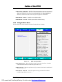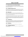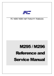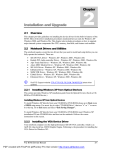
1
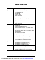
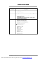
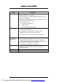
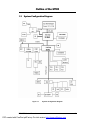
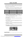
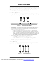
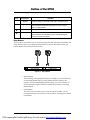
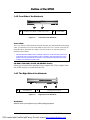
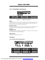
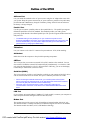
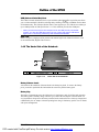
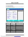
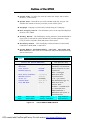
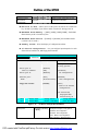
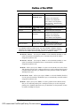
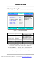
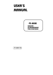
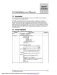
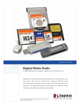
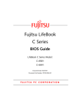
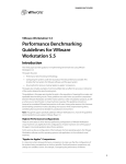
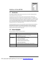
Chapter
Outline of the M785
1.1
Introduction
This chapter provides the outline features and operation of the M785 including the BIOS
Setup program and other system options.
The M785 all-in-one notebook offers the latest in advanced portable computing and
multimedia technology that even outperforms most desktop computers. It incorporates the
latest Intel Pentium 4 Processor running at 400 /533MHz Front Side Bus. It combines support
for the new high-bandwidth Double Data Rate (DDR) 266 SDRAM, Integrated VGA and the
AC 97 audio codec. Built-in Windows 98 / Me / 2000 / XP keyboard, glide pad pointing
device, sound system, PCMCIA slots, USB (Universal Serial Bus) port, advanced power
management and more new multimedia features.
The Intel® Pentium® 4 processor is the evolutionary step for desktop processor technology.
Based on Intel® Net Burst™ micro architecture, the Pentium 4 processor offers higherperformance processing than ever before. Built with Intel's 0.13-micron technology, the
Pentium 4 processor delivers significant performance gains for use in home computing,
business solutions and all your processing needs.
1.2
Feature Highlights
The M785 includes a variety of innovative features:
Features
CPU
Description
• Desktop Intel ® Pentium 4 Northwood Processors using uFCPGA
packaging at 2.0 / 2.2 / 2.26 / 2.4 / 2.53 GHz
• Support FSB 400/533 MHz.
Cache Memory
• L1 Cache (Pentium Processor internal):
12KB code and 8KB data
8-way cache associatively provides
• L2 Cache (Pentium Processor internal):
512KB code and 8KB data
8-way set associative, 32-byte line size, 1 line per sector
Bus Architecture
32-bit PCI/PCI-to-ISA Bus Architecture
Bus Speed
400/533 MHz Front Side Bus
FIC M785 Service Manual
PDF created with FinePrint pdfFactory Pro trial version http://www.pdffactory.com
1-1
Outline of the M785
Features
System Memory
Description
•
Base Memory: 1 SO-DIMM Slot (1.25”)
Size:
128 / 256 / 512MB
Type: DDR SDRAM, 2.5V
Data Path: 64Bit
Frequency: 266MHz
Refresh: CBR Refresh
•
Expansion Memory: 1 SO-DIMM Slot (1.25”)
Size: 128 / 256 / 512MB
Type: DDR SDRAM, 2.5V
Data Path: 64Bit
Frequency: 266MHz
Refresh: CBR Refresh
•
Maximum 32-bit True Color display at 1024x768 pixel resolution
for 14" TFT LCD
•
Brightness controls via hot-key function
•
15” XGA and SXGA+ TFT support, 14.1” XGA TFT support
•
Embedded in SIS 650 Chipset
•
High Performance and high quality 3D accelerator with AGP4X
•
Integrated VB bridge
•
High performance 2D accelerator
•
Complete TV-OUT / Digital Flat Panel Solution
•
Shared with system memory from 8MB ~ 64MB
•
Built-in (internal) 2.5-inch Format; 9.5mm in Height Enhanced
IDE hard drive
•
30 GB or above disk drive options
•
Supports Bus Mastering Ultra-DMA 66 / 100 feature
•
Built-in ATAPI IDE 24X+ Speed CD-ROM drive; or
•
Built-in ATAPI IDE 8X+ Speed DVD-ROM drive; or
•
Built-in ATAPI IDE 4X+ Speed CD-RW drive ; or
•
Built-in ATAPI IDE CD-RW/DVD combo drive
FDD
•
External USB 3.5-inch 1.44MB floppy disk drive
Keyboard
•
19mm Pitch and 3mm Travel
•
Built-in 87 / 90-key Windows keyboard
•
Compatible with IBM enhanced 101 / 102-key keyboard
Display
VGA
HDD
Optical Device
1-2
FIC M785 Service Manual
PDF created with FinePrint pdfFactory Pro trial version http://www.pdffactory.com
Outline of the M785
Features
Pointing Device
PCMCIA Slot
I/O Port
Description
•
Integrated Touch pad (Glide pad) with 2 select click buttons and
1 scroll button
•
PS/2 mouse interface
•
Single-deck PCMCIA 2.1 card slots that support one Type II PC
cards
•
ENE CB1410 (PCI Card Bus controller)
•
PC/Card Bus Type II x1
•
32-bit CardBus PCI local bus technology / Supports mixed
voltage PC cards (5V and 3.3V)
Includes the following standard I/O ports:
•
Serial port: 1 port (D-Sub 9 pin)
•
Parallel port: 1 port (D-Sub 25 pin)
•
VGA CRT port: 1 port (D-Sub 15 pin)
•
USB port: 3 port (ver 2.0)
•
Port Bar: Not support
•
Headphone : 1 Jack
•
MIC In: 1 Jack
•
DC In: 1 port
•
TV out: RCA Jack
•
LAN: 1 port
•
Modem I/F: 1 port
•
IEEE 1394: 1 port
FIC M785 Service Manual
PDF created with FinePrint pdfFactory Pro trial version http://www.pdffactory.com
1-3
Outline of the M785
Features
Audio System
Description
• 16-bit full-duplex sound controller with software wavetable
function and FM stereo synthesizer
• AC97 Audio Codec / Compatible with Sound Blaster Pro. AC’97
Revision 2.1 Compliant
• Integrated 2 high quality paper cone stereo speakers (>1W) with
sound boxes and mono microphone
• Includes the following:
ü
Microphone-in jack (MIC-IN)
ü
Headphone jack
ü
Volume thumb-wheel knob control
•
Universal Auto-switching19V / 90W AC Adapter (100V – 240V)
/ Auto-charging capability
•
Rechargeable Li-Ion (4000mAh/14.8V) Battery Pack
•
Battery Life: 2 hours (Power Management Off)
•
Charging Time: 1.5~2 hours quick charge (computer off)
•
ACPI 1.0B Ready
•
SMM (Intel System Management Mode) fully supported
•
Suspend-to-RAM and Suspend-to-Disk feature / Auto Suspend
hot-key function / Battery Low Auto Suspend
•
Cover Switch (Suspend/CRT-only) function
LED Indicator
•
7 x LED Status Indicators for Power Source, Battery Charge, EMail, IDE, Caps Lock, Scroll Lock, Num Lock (LCD x 3 +
Machine Base x 4)
Modem
•
MDC 56Kbps Fax / Data Internal Modem with V.90 support
LAN
•
Onboard 10BASE-T and 100BASE-TX LAN
Power System
Power
Management
1-4
FIC M785 Service Manual
PDF created with FinePrint pdfFactory Pro trial version http://www.pdffactory.com
Outline of the M785
1.3
System Configuration Diagram
Figure 1-1
System Configuration Diagram
FIC M785 Service Manual
PDF created with FinePrint pdfFactory Pro trial version http://www.pdffactory.com
1-5
Outline of the M785
1.4
Quick Tour of the Notebook
Please take a moment to become familiar with the location and purpose of every control, the
LED status panel, connectors and ports, which are illustrated in this section. It is
recommended to first go through the User Guide of the notebook, which is shipped together
with the notebook for information on how to operate its features.
1.4.1
Inside the Notebook
To open the LCD cover of the notebook, find the cover latch located at the front center of the
LCD cover. Push the latch to the right to release and tilt the LCD cover up. Inside, you will
see the LCD display panel, keyboard, touch pad, status LED, and power switch.
➊
Power Status LED Indicator
➋
Built-in Stereo Speakers
➌
➍
Easy Button
➎
Color LCD Panel
➏
➐
Built-in Stereo Speakers
➑
Keyboard
❾
Figure 1-2
Power On / Resume
Button
Status LED Indicator
GlidePad Pointing
Device
Inside the Notebook
Color LCD Display Panel
The notebook comes with several LCD option sizes at 15” SXGA+ (1400x1050) or 14.1”
XGA (1024x768) active-matrix TFT color liquid crystal display (LCD). You can adjust and
o
tilt (up to 180 ) the LCD screen panel to your desired viewing position.
The notebook computer comes with a color LCD that you can adjust for a comfortable
viewing position. The LCD can be 14.1” TFT color LVDS with 1024x768 XGA (Extended
Graphics Array) resolution panels or 15” TFT color LVDS with 1400x1050 resolution. The
features of the Color LCD Display are summarized as follows:
•
TFT color LVDS with 14.1" 1024x768 XGA or 15" 1400x1050 resolution panels.
•
Capable of displaying 16M colors (32-bit true color) on either size panels.
1-6
FIC M785 Service Manual
PDF created with FinePrint pdfFactory Pro trial version http://www.pdffactory.com
Outline of the M785
•
LVDS display control hot-keys allows you to adjust the brightness of the LCD.
•
Simultaneous display capability for LCD and external desktop computer monitor.
•
LCD display can be 14.1” or 15" TFT.
The notebook uses SiS®650 Host/Memory controller with AGP4X North Bridge Single
Chipset & Built-in High Quality 3D Accelerator VGA graphics controller that owns 8~64MB
shared video memory. All LCD models can support 16M colors or maximum 32-bit true color
at 1024x768 resolution. The notebook also supports simultaneous display of the LCD with the
external VGA monitor.
The LCD screen also uses CCFT (Cold Cathode Fluorescent Tube) backlighting which
consumes much of the electrical power of the notebook. To save battery power, the system
has an advanced power management feature that switches off the LCD when there is no
system activity for a predetermined amount of time.
You adjust the brightness level of the LCD by pressing the display control hot-keys. You
activate the hot-keys by pressing the <Fn> key along with another function key:
•
•
<Fn> + <F8> Key = Increases the brightness of the LCD display
<Fn> + <F9> Key = Decreases the brightness of the LCD display
Keyboard Panel
−
Standard QWERTY-key layout and full-sized 87 / 90 keys keyboard with
Windows hot-keys, embedded numeric keypad, hot keys, inverted “T” cursor
arrow keys, and separate page screen control keys.
Wide extra space below the keyboard panel for your wrist or palm to sit-on
comfortably during typing. (The keypad F4, F5, F7 on the following keyboard
should no words print on it.)
−
Œ
Function Keys
•
Windows Short-cut Key
Figure 1-3
•
•
‘
Control Keys
Ž
Windows
Start Menu Key
Cursor Control Keys
Keyboard Layout
The notebook keyboard is a little bit different from a standard desktop keyboard. Aside
from the normal alphanumeric characters and the standard keyboard function keys, the
FIC M785 Service Manual
PDF created with FinePrint pdfFactory Pro trial version http://www.pdffactory.com
1-7
Outline of the M785
notebook keyboard includes an embedded numeric keypad, and special function keys that
activates by pressing the <Fn> key together with another key. These special function keys
or “hot-keys” allow you to control and adjust some of the functions of the notebook like
display controls, power saving features, and others.
(1) Function Keys — These function keys, out of <F1> through <F12>, are available on
the notebook keyboard. These keys also work together with the <Fn> key to activate
special functions. The following function-key combinations are pre-programmed:
Hot Key
Fn + F3
Function
Toggle Display (LCD/CRT/Simul)
Fn + F6
Fn + F8
Fn + F9
Speaker On/Off
Brightness Increase
Brightness Decrease
Handler
BIOS Handler
BIOS Handler
Controlled by PMU07
Controlled by PMU07
(2) Control keys – <Ctrl>, <Alt>, <Fn>, and <Shift> keys are controls used in
conjunction with other keys to change their functions. To use control keys, press and
hold the control key while pressing another key. For example, “Press <Ctrl>+ <C>”
means to hold down the <Ctrl> key and type the letter <C>.
(3) Windows keys (Windows Start Menu Key) – Use this key to activate the Start
Menu of Windows.
(4) Shortcut/Application key – provides quick access to shortcut menus. (This key acts
like a right mouse button.)
(5) Cursor Control keys – Cursor control keys let you position the cursor on the screen
where you want. On the screen, the cursor is a blinking underline, block, or vertical
bar depending on the application.
(6) Typewriter keys – Typewriter keys (also called alphanumeric keys) are used to enter
text and characters. Keys with blue print on them behave differently when combined
with control keys or the <Fn> key.
(7) Numeric Keypad – Pressing <NumLock> on the keyboard activates the embedded
numeric keypad numbers and functions printed in blue on top of the keys. When you
press <NumLock> again, the keys revert to their normal functions as typewriter keys.
Figure 1-4
Embedded Numeric Keypad
Integrated Microphone
This allows you to instantly record voice annotations (normally saved as WAV files) and later
1-8
FIC M785 Service Manual
PDF created with FinePrint pdfFactory Pro trial version http://www.pdffactory.com
Outline of the M785
attached them to documents and presentation using the notebook integrated audio system and
application software. Since the notebook also supports full-duplex audio capabilities, you can
talk to the microphone and at the same time listen to others talk when connected to a
speakerphone modem, Internet live chat, or video conferencing.
Power Status LED Indicator
Located just on TFT LED panel assembly, you will find three LEDs for the power and battery
charge status. These LEDs are positioned to be visible even if the LCD cover is closed.
Œ
Power Indicator
•
Battery Charging LED
Figure 1-5
Ž
Mail LED
Power Status LED Indicator
1. Power Indicator – lets you know if power to the system is turned on and if system is in
Suspend-to-RAM mode. This LED is positioned so that you can see it on both sides
whether the LCD panel is opened or closed.
− Lights green when the system is powered on using the AC adapter or battery.
− Lights green blinking when in Suspend to RAM mode and critically low battery
power. We strongly recommend that users create the partition "Save to Disk" (for
Win98 only) as this will prevent your data from loss when power is critically low.
For Windows version later then Win98, please use hibernation mode instead.
2. Battery Charging LED – lights to indicate battery in charging status.
− Lights organge to indicate the battery is charging.
− Lights off to indicate the battery is fully charged or no battery installed.
3. Mail LED – Lights green to indicate that a new mail is arrived.
Status LED Panel
The Status LED Panel keeps you informed of the notebook’s current operating status. Each
LED is marked with an icon to designate a system status.
Figure 1-6
Status LED Panel Icons
FIC M785 Service Manual
PDF created with FinePrint pdfFactory Pro trial version http://www.pdffactory.com
1-9
Outline of the M785
Icon
Represents
Indicates
Œ
IDE Drive
Access
This LED will turn on when the system is accessing the hard
disk drive (HDD) or CD-ROM / DVD-ROM / CD-RW /Combo.
•
Caps Lock
This LED will turn on when the Caps Lock key is activated.
When activated, all alphabet keys typed in will be in upper
case or in capital letters.
Ž
Scroll Lock
This LED will turn on when the Scroll Lock key is activated.
•
Num Lock
This LED will turn on when the Num Lock key is activated.
When activated, the embedded numeric keypad (blue print
numeric keys) will be enabled.
Easy Buttons
There are three easy buttons, two use for accessing Internet and e-mail functions instantly and
easily, the other one lets you define certain functions by yourself. Description of the easy
buttons appears in the latter part of this section.
Œ
Internet Button
•
E-Mail Button
Figure 1-7 Easy Button
− Internet Button
This technology is designed specifically for providing a very convenient way
in connecting Internet only by pressing Internet button as shown in the
graphics. For more understanding and interesting, you can refer Section 2.5
of user manual to recognize the driver installation procedures in activating
Internet button.
− E-mail Button
This is the most convenient way to access the outlook 98/2000... just by
pressing this button, you can omit several procedures in entering into Outlook
environment.
1-10
FIC M785 Service Manual
PDF created with FinePrint pdfFactory Pro trial version http://www.pdffactory.com
Outline of the M785
Power Button
Press the Power button either to power on or power off the system. The Power button is also a
“Smart” switch, meaning that it recognizes when the system is in Suspend mode. If in
Suspend mode, pressing the Power button will bring it out of Suspend mode and resume to
the system’s last state. You can set the function of power button from the power management
setting in Windows Control Panel. Always check the Power LED after pressing the power
button to know the power status of the notebook.
o
If you are unable to power off the system, use the power override function. Press the
power button and hold it in place for four seconds. The system will then power off.
Touch Pad Pointing Device
Built in just below the keyboard panel is the glide pad pointing device. The left and right
select buttons of the glide pad is found below the glide pad surface. The left select button is
configured (by default) as the left button you normally click on the left button of your mouse,
while the right select key is configured as the right mouse button. The scroll button makes it
easy to browse upwards or downwards in the software screen.
To move cursor, place your finger lightly on the glide pad and move in the desired direction.
If you reach the end of the pad, lift your finger and place it back down on the other side.
The glide pad is compatible with the standard PS/2 mouse and can be activated using the
normal DOS or Windows PS/2 mouse driver. You can also disable the glide pad in the BIOS
Setup program.
o
You can execute a left button click function by simply tapping on the glide pad
surface once. Refer to the User Guide of the notebook for more information.
Built-in Stereo Speakers
At the front left and right sides of the base unit are two built-in stereo mini speakers
with sound boxes. The speakers are controlled by the audio controller of the notebook
and activated by installing the audio driver. For adjusting the volume of the speakers,
you can use the volume control program under Microsoft OS or by adjusting the
thumb-wheel volume knob also found on the right side of the notebook.
FIC M785 Service Manual
PDF created with FinePrint pdfFactory Pro trial version http://www.pdffactory.com
1-11
Outline of the M785
1.4.2 Front Side of the Notebook
Œ
CD-ROM, DVD-ROM, CD-RW/DVD Combo
Figure 1-8
•
Cover Switch
Front Side of the Notebook
Cover Switch
The Cover Switch is found inside the notebook assembly just underneath the latch opening
where you insert the LCD cover hook. Whenever the LCD cover is closed, it activates the
Suspend mode or shut down the computer. The action can be set on Power Option of
Windows Control Panel.
o
When Suspend-to-RAM mode is activated, make sure not to leave the system for a
long period when running at battery mode. The battery will continue to drain some
power even in Suspend mode. It is better to save all files and shutdown the power
instead or run Suspend-to-Disk mode.
CD-ROM, DVD-ROM, CD-RW, CD-RW/DVD Combo
Allows you to load and start programs from a compact disc (CD) or a digital video
disc (DVD) and play conventional audio CDs.
1.4.3 The Right Side of the Notebook
Œ
Air-Outlet Vent
Figure 1-9
•
Locking Device Keyhole
Right Side of the Notebook
Air Inhalant
Inhale the air into your computer to keep it within operating temperature
1-12
FIC M785 Service Manual
PDF created with FinePrint pdfFactory Pro trial version http://www.pdffactory.com
Outline of the M785
1.4.4
The Left Side of the Notebook
Œ
•
IR Port
•
Microphone Jack
Volume Control
➎
PC Card Slots
Figure 1-10
Ž
Headphone Jack
Left Side of the Notebook
IR Port
Wireless data transfer of files between your notebook computer and an IR-equipped device or
notebook computer. You can also print to an IR-equipped printer without using cables. The
SIR mode provides up to 115.2Kbps of data transfer rate
Microphone Jack
Allows you to connect an external microphone for monophonic sound recording directly into
your notebook computer. Plugging in an external microphone disables the built-in
microphone.
Headphone Jack
Lets you plug in a stereo headphone, powered speakers, or earphone set with 1/8 inch phono
plug or SPDIF connector for personal listening
Volume Control
Allows you to control the speaker volume
PC Card Slots
1.4.5 The Rear Side of the Notebook
Œ
•
’
➓
AC Power Port
Parallel Port
USB Port
Modem Port
Figure 1-11
•
•
“
Air Inhalant
Serial Port
IEEE 1394 Port
Ž
‘
”
CRT Port
TV-Out Port
LAN Port
Rear Side of the Notebook
FIC M785 Service Manual
PDF created with FinePrint pdfFactory Pro trial version http://www.pdffactory.com
1-13
Outline of the M785
AC Power Port
Lets you attach the notebook to the AC power source using the AC adapter that comes with
your system. Keep the system connected to AC power whenever possible to keep the battery
pack and internal CMOS battery charged. The Battery Charge LED will activate whenever
the battery is being recharged.
Parallel Port
Use this port to connect a parallel printer or other parallel device. The parallel port supports
Enhanced Capabilities Port (ECP) standard. The standard provides you with a greater
processing speed than the conventional parallel port. The port also supports Bi-directional and
EPP protocols.
o
The default setting for the parallel port on your notebook computer is set to
Enhanced Capabilities Port (ECP). Some older parallel devices may not function with
the ECP default setting. You may need to adjust the setting to accommodate your
parallel device by changing the BIOS setting.
TV-Out Port
Lets you connect to a S-video TV connector for presentation or VCD, DVD watching.
Air Inhalant
Inhale the air into the computer to keep it within operating temperature.
CRT Port
The VGA port lets you connect an external VGA (CRT) monitor to the notebook. You can
also run the LCD and the external CRT monitor display simultaneously; or switch it to CRT
only using the function hot key (Fn+F3). When switch to CRT only, you can set the display
resolution up to 1024x768 at (16-bit true color).
Serial Port (COM 1)
The 9-pin serial port provides a serial interface to which you can connect an RS-232C device
such as external serial mouse or modem. This port is commonly referred to as COM1.
o
o
When connecting an external serial mouse, you must first power off the system
before connecting the external mouse. It can auto-detect the serial mouse hardware
and run both glide pad and serial mouse simultaneously.
Whenever using an external mouse in place of the built-in glide pad, it is
recommended to switch the mouse driver to the default standard Microsoft mouse
driver.
LAN Port
If you purchase an internal 10Base-T/100Base-TX LAN module, it connects your computer to
other computers/networks through a local area network (LAN).
Modem Port
The modem port provides a reserve jack for installing an internal modem with RJ-11 jack.
The internal modem is a 56Kbps-fax/data PCI modem and supports the latest V.90 standard.
The internal module uses MDC (AC'97) S/W Modem technology.
1-14
FIC M785 Service Manual
PDF created with FinePrint pdfFactory Pro trial version http://www.pdffactory.com
Outline of the M785
USB (Universal Serial Bus) Ports
The USB (Universal Serial Bus) Port is a port with the symbol
. This 4-pin slim port allows
you to connect multiple USB devices through daisy chaining or through a USB hub and use them
all simultaneously. The USB specification states it can support up to 127 USB devices running at
up to 12Mbps based on USB specification v1.1. This notebook provides four USB ports.
o
When you resume the system from suspend mode, the USB port may not initialize
properly. If in case the USB device does not work, unplug and plug the USB device
again. This is a known bug released by Intel and Microsoft Windows.
IEEE 1394
IEEE 1394 port is a high speed I/O port that can transfer high levels of data in real-time, such
as external hard disk, Digital Video Camera.
1.4.6 The Under Side of the Notebook
Œ
Battery Release Latch
Figure 1-12
•
Battery Bay
Under Side of the Notebook
Battery Release Latch
Also found on the underside of the notebook is the battery bay latch. To remove the battery
pack, you need to push aside this latch and at the same time pull the battery pack.
Battery Bay
The battery compartment stores the Lithium-Ion (Li-Ion) battery pack for off-the-cord operation.
The battery pack is instantly charge whenever you connect the AC adapter to the notebook. It is
very important to always have the battery installed on the notebook to have it always charged and
conditioned by the AC adapter. Normal operating time using Li-Ion battery pack is close to 2hours
with power management.
FIC M785 Service Manual
PDF created with FinePrint pdfFactory Pro trial version http://www.pdffactory.com
1-15
Outline of the M785
1.5
System BIOS SETUP Program
The notebook uses the Phoenix BIOS Setup program that allows you to set several system
configurations in changing the way the system performs. This includes your system time and
date, disk drive configuration, I/O device controls, boot drive sequence, and power
management settings. The information is then stored in the CMOS RAM chip and will remain
permanent unless you change it again. The notebook also uses EPROM Flash BIOS that
allows you to update the system BIOS by simply overwriting it using the Phoenix Flash
programming utility.
Before boot-up, the system will read the BIOS settings and compare them to the equipment
check conducted during the POST (Power-On Self-Test). If an error occurs, an error message
will be displayed on the screen, and you will then be prompted to run the BIOS Setup
Program. Press the <F2> key to run the BIOS Setup program. The BIOS Setup program is
organized into five menus which you can select using the <ß> and <à> keys. To move from
one option to another, you use the up and down arrow keys.
On the BIOS Setup program, you will find the following parts on the screen:
•
Menu Bar - found on the top line of the screen. Each of the five items has a separate
menu screen.
•
Parameters - found on the left side of the screen. This area lists the parameters and
their current settings.
•
Item Specific Help - found on the right side of the screen. This area describes each
parameter and its available settings.
•
Key Status Bar- the bottom part of the screen. These lines display the keys available
to move the cursor, select a particular function and so forth.
The following table lists the keys on how to edit and move around the setup menus inside.
o
KEY
WHAT IT DOES
<F1>
Shows on-line help on key functions.
↑ ↓
Moves the cursor between the displayed parameters.
+/-
Modifies the current parameter settings.
<F9>
Load default configuration.
Esc
Exits the current menu and returns to the main menu or go directly to
the Exit menu.
ßà
Changes between displayed menus.
<Enter>
For some parameter settings, select and moves the cursor between
the sub-menu. Also moves the cursor to the next line or selection.
<F10>
Save changes and exit.
Some information here may not be available or different from other date code
versions of the notebook BIOS. Always check for the latest BIOS update from the
FIC Internet homepage. ftp://pcg.fic.com.tw/NBTECH
1-16
FIC M785 Service Manual
PDF created with FinePrint pdfFactory Pro trial version http://www.pdffactory.com
Outline of the M785
1.5.1 Using the Main Menu
The BIOS Setup Main Menu contains the settings for system time and date, and disk drives as
well as CPU and system memory information.
P h o e n i x B IO S S et u p U t i l i ty
Main
Advanced
Security
Boot
Exit
Item Specific Help
4
F1
System Time:
[07:24:00]
System Date:
[07/16/2002]
Language:
[English
Boot Display Device:
[Both]
Primary Master
[FUJITSU MHR2020AT]
Secondary Master
Installed CD/DVD
System Memory
640 KB
Extended Memory
228352 KB
CPU Type
Intel® Pentium® 4
CPU Speed
2000 MHz
BIOS Version
1.0A-1.10-0812
Help
Esc Exit
<Tab>, <Shift-Tab>, or
<Enter> selects field.
(US)]
h
Select Item
-/+
Change Values
F9
‘’
Select Menu
Enter
Select 4 Sub-Menu
F10 Save and Exit
Figure 1-12
Setup Defaults
BIOS Setup Main Menu
System Time:
[07:24:00]
<Tab>, <Shift-Tab>, or <Enter> selects
field.
System Date:
[07/16/2002]
Language :
[English (US)]
<Tab>, <Shift-Tab>, or <Enter> selects
field.
(BIOS auto detect, for information only)
Boot Display Device:
[Both] / [LCD] / [CRT]
Select the display device.
Primary Master
[FUJITSU MHR2020AT]
Secondary Master
Installed CD/DVD
(BIOS auto detect, for information only)
System Memory
640 KB
(BIOS auto detect, for information only)
Extended Memory
228352 KB
(BIOS auto detect, for information only)
CPU Type
Intel® Pentium® 4
(BIOS auto detect, for information only)
CPU Speed
2000MHz
(BIOS auto detect, for information only)
BIOS Version
1.0A-1.10-0812
(BIOS auto detect, for information only)
FIC M785 Service Manual
PDF created with FinePrint pdfFactory Pro trial version http://www.pdffactory.com
1-17
Outline of the M785
n System Time – To set the time, enter the current hour, minute, and second on
hr/min/sec, 24-hour format.
n System Date – This field lets you set the calendar month, day, and year. The
calendar clock remains in memory even after you turn off the system.
n Language – Language for each country. Default setting as US language.
n Boot Display Device – This field allows you to set the output boot display to
the LCD, CRT, or Both.
n Primary Master – This field displays various parameters for the hard disk drive.
If type [Auto] is selected, the system automatically sets these parameters. If type
[User] is selected, Cylinders, Heads and Sectors can be edited.
n Secondary Master – This field displays various parameters for the internal
CD-ROM or a DVD-ROM / Combo Drive.
n System Memory, Extended Memory, CPU Type, CPU Speed and
BIOS Version – These fields are for information only as the BIOS automatically
detects related values.
P h o e n i x B IO S S et u p U t i l i ty
Main
Internal HDD [FUJITSU MHR2020AT]
Item Specific Help
Type:
LBA Format
[Auto]
User = you enter
Parameters of hard-disk
Total Sectors:
39070080
Drive installed at this
Maximum Capacity:
20004MB
connection.
Auto = autotypes
Multi-Sector Transfers:
[16 Sectors]
Hard-disk drive
LBA Mode Control:
[Enabled]
Installed here.
32 Bit I/O:
[Disabled]
1-39 = you select
Transfer Mode:
[Fast PIO 4]
Pre-determined type of
Ultra DMA Mode:
[Mode 2]
Hard-disk drive
Install here.
CD-ROM = a CD-ROM drive
Is installed here.
ATAPI Removable =
Removable disk drive is
installed here.
Help h
Esc Exit ßà
F1
Select Item −/+
Change Values
Select Menu Enter
Select 4Sub-Menu F10
Figure 1-13
1-18
F9
Setup Defaults
Save and Exit
Internal HDD/CD-ROM Sub-Menu
FIC M785 Service Manual
PDF created with FinePrint pdfFactory Pro trial version http://www.pdffactory.com
Outline of the M785
Type:
[None] / [ATAPI
Removable] / [CD-ROM] /
[User] / [Auto]
Select the drive type corresponding to the
fixed disk installed in your system. If type
USER is selected, Cylinders, Heads &
Sectors edited directly.
Total Sectors:
39070080
(BIOS auto detect, for information only)
Maximum Capacity:
20004MB
(BIOS auto detect, for information only)
Multi-Sector
Transfers:
[Disabled] / [2 Sectors] /
[4 Sectors] / [8 Sectors] /
[16 Sectors]
Determine the number of sectors per
block for multiple sector transfers.
LBA Mode Control:
[Disabled] / [Enabled]
Enabling LBA causes Logical Block
Addressing to be used in place of
Cylinders, Heads & Sectors
32 Bit I/O:
[Disabled] / [Enabled]
This setting enables or disables 32 bit
IDE data transfers
Transfer Mode:
[Standard] / [Fast PIO 1] /
[Fast PIO 2] / [Fast PIO 3] /
[Fast PIO 4] / [FPIO 3 /
DMA1] / [FPIO 4 / DMA2]
Select the method for moving data
to/from the drive. Autotype the drive to
select the optimum transfer mode
Ultra DMA Mode:
[Disabled] / [Mode 1]
[Mode 2]
(BIOS auto detect, for information only)
1.5.2 Using the Advanced Menu
The Advanced Menu allows you to configure the OS and I/O device settings.
P h o e n i x B IO S S et u p U t i l i ty
Main
Advanced
Security
Boot
Exit
Item Specific Help
NumLock:
[Off]
Selects Power-on
State for NumLock
4
F1
Embedded Share Memory
[32MB]
EmbedDed Audio Device
[Enabled]
Summary Screen:
[Disabled]
I/O Device Configuration
Help
Esc Exit
h
Select Item -/+
Change Values
‘’
Select Menu Enter
Select 4Sub-Menu F10
Figure 1-14
F9
Setup Defaults
Save and Exit
BIOS Setup Advanced Menu
NumLock:
[On] / [Off]
Selects Power-on state for NumLock
Embedded Share
Memory
[8MB] / [16MB] / [32MB] /
[64MB]
Embedded Share Memory size for AGP
VGA memory.
EmbedDed Audio
Device
[Enabled] / [Disabled]
Enabled or Disabled SiS Embeded
Audio ( SiS 7018 AC97 Audio )
FIC M785 Service Manual
PDF created with FinePrint pdfFactory Pro trial version http://www.pdffactory.com
1-19
Outline of the M785
Summary screen:
[Disable] / [Enabled]
Display system configuration on boot
4I/O Device
Submenu
Peripheral Configuration
Configuration
n Num-Lock on Boot – Allows you to set the power-on state for the <NumLock>
key. Set this to [LockOn] if you want to enable <NumLock> during power on.
n Embedded Share Memory – [8MB] [16MB] [32MB] [64MB] – Embedded
Share Memory AGP VGA Memory Size.
n EmbedDed Audio Device – [Enabled] or [Disabled] SiS Embeded Audio
( SiS 7018 AC97 Audio )
n Summary Screen – Select the display of configuration on Boot.
n I/O Device Configuration – Lets you configure input/output device such
as Serial Port, Parallel Port, and Floppy disk controller.
P h o e n i x B IO S S et u p U t i l i ty
Advanced
I/O Device Configuration
Item Specific Help
Configure serial port
A using options:
Serial port A:
[Enabled]
Base I/O address
[2F8]
[Disabled]
Serial port B:
[Enabled]
Parallel port:
[Auto]
Mode:
No configuration
[Enabled]
[Bi-directional]
Floppy disk controller:
[Enabled]
User configuration
[Auto]
BIOS or OS chooses
configuration
(OS Controlled)
Displayed when
Controlled by OS
Help h
Esc Exit ‘’
F1
Select Item -/+
Change Values
Select Menu Enter
Select 4Sub-Menu F10
Figure 1-15
Serial port A
F9
Setup Defaults
Save and Exit
I/O Device Configuration Sub-Menu
[Disabled] / [Enabled]
/ [Auto]
Configure serial port A using options:
Disabled - No configuration,
Enabled - User configuration,
Auto - BIOS or OS configuration.
(OS Controlled) – Displayed when
1-20
FIC M785 Service Manual
PDF created with FinePrint pdfFactory Pro trial version http://www.pdffactory.com
Outline of the M785
controlled by OS
Serial port B
[Disabled] /
[Enabled] / [Auto]
Configure serial port A using options:
Disabled - No configuration,
Enabled - User configuration,
Auto - BIOS or OS configuration.
Mode:
Base I/O address/IRQ
Interrupt
Parallel port
[IrDA] [FIR]
[3F8] / [2F8] / [3E8] /
[2E8]
[IRQ 3] / [IRQ4]
[Disabled] / [Auto] /
[Enabled]
(OS Controlled) – Displayed when
controlled by OS
Enabled the IrDA transmission
Set the base I/O address and IRQ for
serial port B.
Set the interrupt for serial port B.
Configure parallel port using options:
Disabled - No configuration,
Enabled - User configuration,
o
Mode
[Bi-directional] /
[EPP] / [ECP]/
Base I/O address
[378] / [278] / [3BC]
Auto - BIOS or OS configuration.
Set the mode for the parallel port using
options:
Output only, Bi-directional
Select the base I/O address for the
parallel port when port is Enabled.
If you disable a device in BIOS Setup, you cannot enable or assign it using the
Windows (98 or 2000) Device Manager. The device is not listed in the Windows
device list. You need to select any setting other than “Disable” in Setup.
n Serial Port A – You can press <Enter> to select Enabled, Disabled, or Auto
option for enabled or disabled the port, or automatically sensed the address
assignment by BIOS or OS.
n Serial Port B – You can press <Enter> to select Enabled, Disabled, or Auto
option for enabled or disabled the IrDA, or automatically sensed the address
assignment by BIOS or OS.
n Mode – Allows you to press <Enter> to select a serial mode B as 3F8, 2F8, 3E8 &
2E8 when the serial port B is configured. When you set the configured serial port B
to Enabled rather than Auto, you should also set the parameter of Base I/O address
and IRQ for this port.
n Parallel Port – Allows you to press <Enter> to select the Enabled, Disabled,
or Auto option for enabled or disabled this port, or automatically sensed the address
assignment by BIOS or OS.
n Mode – Allows you to press <Enter> to select a parallel mode as Bi-directional,
EPP, or ECP when the parallel port is configured. When you set the configured
parallel port to Enabled rather than Auto, you should also set the parameter of Base
I/O address and IRQ for this port.
FIC M785 Service Manual
PDF created with FinePrint pdfFactory Pro trial version http://www.pdffactory.com
1-21
Outline of the M785
1.5.3
Using the Security Menu
The Security menu allows you to set the system password as well as disk-protection security.
P h o e n i x B IO S S et u p U t i l i ty
Main
Advanced
Security
Boot
Exit
Item Specific Help
Supervisor Password Is:
User Password Is:
Clear
Clear
Set Supervisor Password
[Enter]
Set User Password
[Enter]
Diskette access:
[Supervisor]
Password on boot:
[Disabled]
Supervisor Password
controls access to the
F1
Help
Esc Exit
h
Select Item -/+
setup utility.
Change Values
‘’ Select Menu Enter Select Sub-Menu
Figure 1-16
F9
Setup Defaults
F10 Save and Exit
BIOS Setup Security Menu
Supervisor Password Is:
Clear / Set
While the Supervisor Password had
been enabled, the item will show Set. If
disabled. The item will show Clear.
User Password Is:
Clear / Set
While the User Password had been
enabled, the item will show Set. If
disabled. The item will show Clear.
Set Supervisor Password
Press [Enter]
Supervisor Password controls access to
the setup utility.
Set User Password
Press [Enter]
User Password controls access to the
system.
Diskette access
[User] / [Supervisor]
Control access to diskette drives.
Password on boot
[Disabled] / [Enabled]
Enabled password entry on boot
n Supervisor Password Is: Clear / Set –While the Supervisor Password had
been enabled, the item will show Set. If disabled. The item will show Clear.
n User Password Is: -- Clear / Set – While the User Password had been
enabled, the item will show Set. If disabled. The item will show Clear.
n Set Supervisor Password – Specifies if the system prompts you to enter a
password when entering Setup.
1-22
FIC M785 Service Manual
PDF created with FinePrint pdfFactory Pro trial version http://www.pdffactory.com
Outline of the M785
n Set User Password – Specifies if the system prompts you to enter a password
when accessing the system. The Set User Password function will be enabled once a
Supervisor password is set. Enter a new password with up to eight alphanumeric
characters, and then enter this same new password again for confirmation.
n Diskette access – Controls access to diskette drive.
n Password on boot – Enables password check when booting.
1.5.4
Using the Boot Menu
The Boot menu lets you decide the boot order of booting devices including:
P h o e n i x B IO S S et u p U t i l i ty
Main
Advanced
Security
Boot
Exit
Item Specific Help
CD-ROM Drive
+ Hard Drive
Keys Used to views or
Removable Devices
Configure devices:
<Enter> expands or
collapses devices with
a + or <Ctrl+Enter> expands
All
<Shift + 1> enables or
Disables a device.
<+> and <-> moves the
Device up or down.
<n>May move removable
Device between Hard
Disk or Removable Disk
<d> Remove a device
That is not installed.
F1 Help
h
Esc Exit
‘’ Select Menu Enter Select Sub-Menu F10 Save and Exit
Select Item -/+
Figure 1-17
Change Values
F9
Setup Defaults
BIOS Setup Boot Menu
n CD-ROM Drive – Move the option on top if you want to boot from a bootable
CD-ROM like Windows NT/2000/XP (Optical Drive D:\).
n Hard Drive – Move the option on top if you want to boot from a bootable hard
disk drive (Drive C:\)
n Diskette Devices – Move the option on top if you want to boot from a
bootable floppy diskette (Drive A:\).
FIC M785 Service Manual
PDF created with FinePrint pdfFactory Pro trial version http://www.pdffactory.com
1-23
Outline of the M785
1.5.5
How to Exit the Setup Program
There are two choices to escape from the Setup program.
P h o e n i x B IO S S et u p U t i l i ty
Main
Advanced
Security
Boot
Exit
Item Specific Help
Exit Saving Changes
Exit Discarding Changes
Exit System Setup and
save your changes to
Load Setup Defaults
CMOS.
Discard Changes
Save Changes
Battery Refresh
F1
Help
Esc Exit
h
Select Item -/+
Change Values
F9
Setup Defaults
‘’ Select Menu Enter Select Sub-Menu F10 Save and Exit
Figure 1-18
BIOS Setup Exit Menu
n Exit Saving Changes – Exits System Setup and saves your changes to
CMOS.
n Exit Discard Changes – Exits Setup utility without saving Setup data to
CMOS.
n Load Setup Defaults – Loads the default settings for all items in Setup.
n Discard Changes – Reverts to previously selected settings.
n Save Changes – Saves Setup data to CMOS.
n Battery Refresh – Reactivate both Li-Ion and Ni-MH battery.
1-24
FIC M785 Service Manual
PDF created with FinePrint pdfFactory Pro trial version http://www.pdffactory.com
Outline of the M785
1.6
Notebook Accessories and System Options
It is also important to understand the accessories that come along with the notebook and the
options for fully utilizing the capabilities of the computer. This section describes briefly what
these accessories and options are.
1.6.1
AC Adapter and Power Cord
The AC Adapter supplies external power to your computer and at the same time charges the
internal battery pack. The AC adapter has an auto-switching design that can connect to any
100VAC ~ 240VAC power outlets. Connect the adapter to the AC wall outlet using the power
cord. There is an LED on the AC adapter to indicate if DC power is already available.
1.6.2
Battery Pack
Aside from the AC adapter, your computer can also be powered through the removable
battery pack. The battery pack uses rechargeable or Lithium-Ion (Li-Ion) battery cells that can
run for 2 hours when fully charged and power management enabled. Recharging the battery
takes around 2 hours when the computer is off.
You should always leave the battery inside your computer even when using the AC adapter as
it also acts as back-up power supply in case power from the AC adapter is cut off. It is also
very important to have the battery pack always charged to prevent battery cell degradation. If
the AC adapter is not connected or not available, and the notebook is not going to be used for
some period, it is advisable to remove the battery pack from the notebook to prevent any
current leak.
1.6.3
DVD-ROM Drive
Other than the internal CD-ROM drive, the notebook also provides optional factory built-in
DVD-ROM drive. DVD-ROM drives are also backward compatible with CD-ROM, so you
can also use any audio CDs, video CDs, photo CDs, and CD-R. Using a software MPEG2/DVD program, the notebook can playback any commercial DVD movie titles.
1.6.4
CD-RW Drive
This device pack can write data to CD-R or CD-RW CD for you to backup the data.
1.6.5
CD-RW/DVD Combo Drive
This device pack can write data to CD-R or CD-RW CD for you to backup the data and also
can read DVD/CD title.
FIC M785 Service Manual
PDF created with FinePrint pdfFactory Pro trial version http://www.pdffactory.com
1-25