1
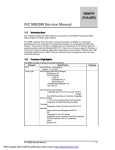
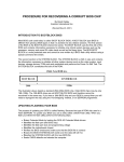
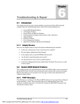
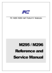
Chapter
Installation and Upgrade
2.1
Overview
This chapter provides guidelines on installing the device drivers for the built-in features of the
M785. Most of the driver installation procedures mentioned here are only for Windows XP
Windows 2000, and Windows Me. This chapter also includes procedures on how to upgrade
major internal system components like CPU, memory, hard disk, and feature card modules.
2.2
Notebook Drivers and Utilities
The notebook requires several device drivers that you need to install and setup before you can
fully operate the notebook. These are:
•
•
•
•
•
•
•
•
•
i
2.2.1
SiS 650 VGA Driver – Windows XP , Windows 2000 , Windows Me
Realtek PCI Audio controller Driver – Windows XP , Windows 2000 , Windows Me
Alps Touch Pad Driver – Windows XP , Windwos 2000 , Windows Me
Askey MDC Modem Driver – Windows XP , Windows 2000 , Windows Me
SIS LAN Driver– Windows XP , Windows 2000 , Windows Me
EzButton Driver – Windows XP , Windows 2000 , Windows Me
SMSC FIR Driver – Windows XP , Windows 2000 , Windows Me
EzMail Driver – Windows XP , Windows 2000 , Windows Me
Ezbuttom Driver – Windows XP , Windows 2000 , Windows Me
Visit FIC Support website FTP://FTP.PCG.FIC.COM.TW/NBTECH latest driver
updates.
Installing Windows XP from Optical Devices
This section provides Windows XP installation guide from the Optical Devices (Such as CDROM or DVD-ROM device.)
Installing Windows XP from Optical Devices
To install Windows XP directly from your CD-ROM or DVD-ROM, please go to Boot menu
of BIOS setup menu. Use arrow key to select "CD-ROM Drive", then use "+" or "-" to move
it to the top. Go to Exit menu and select “Exit Saving Changes”.
To install Windows XP directly from your CD-ROM or DVD-ROM, insert Windows XP
installation CD into CD-ROM drive and boot on the notebook. Follows the screen
instructions on the screen.
2.2.2
Installing the VGA Device Driver
Your notebook computer uses the high-performance SiS 650 VGA controller, which is an
AGP 4X video local bus, 2D/3D Graphic Engine. Following is the procedure for installing the
VGA Driver for Windows XP:
FIC M785 Service Manual
PDF created with FinePrint pdfFactory Pro trial version http://www.pdffactory.com
2-1
Installation and Upgrade
Installing VGA Driver for Windows XP
Following is the procedure for installing the Video Accelerator 3D Adapter (English) VGA
driver to your computer:
1.
Click the Start button, and then point to Run. The Run dialog box appears.
2.
Click the Browse button and specify the directory as.
"E:\Drivers\WinXP\VGA\Setup.exe"
3.
Implement the setup program to install this driver. The Welcome dialog box appears.
4.
Click Next to process the further step continuously when screen displays this command.
5.
Press Finish to restart your system.
2.2.3
Installing the Audio Device Driver for Windows XP
Your notebook computer uses Realtek Audio Controller.
1.
Click the Start button, and then point to Run. The Run dialog box appears.
2.
Click the Browse button and specify the directory as.
"E:\Drivers\WinXP\Audio\Setup.exe" where the audio driver is located
3.
Implement the setup program to install this driver. The Welcome dialog box appears.
4.
Click Next to process the further step continuously when screen displays this command.
5.
Press Finish to restart your system.
2.2.4
Installing EzButton Driver for Windows XP
Following is the procedure for installing the Internet, e-mail button and Audio DJ keys.
Installing EzButton driver for Windows XP
1.
Boot WinXP from your hard disk and insert the disc containing the EzButton driver for
WinXP.
2.
Double-click on the System icon, Hardware and then click on the Device Manager
folder tab.
3.
Double-click Standard 101/102 key or Microsoft Natural PS/2 keyboard... and Select
Update Driver
4.
Select Install from a list of specific location (Advanced) and then click Next
5.
Tick on "Include this location in the search". Then, click Browse button and navigate to
the EzButton driver location as "E:\Drivers\WinXP\EzButton". Click Next to begin
searching the driver.
2-2
FIC M785 Service Manual
PDF created with FinePrint pdfFactory Pro trial version http://www.pdffactory.com
Installation and Upgrade
6.
The Add New Hardware will found Keyboard en3886... Click Next to continue the
driver installation.
7.
Click Finish button to finish installing EzButton driver.
8.
Click Yes to restart the computer
2.2.5
Installing Easy Mail Light Driver for Microsoft Outlook
98/2000...
1.
Installing Easy Mail Light driver for Windows XP
2.
Boot Windows from your hard disk and insert the disc containing the Easy Mail Light
button driver.
3.
Click the Start button, then click Run. In the Run dialog box, click Browse button and
navigate to the directory as "E:\Drivers\WinXP\EzMail\EzMail.exe"
4.
Run the execution file for installing the EzMail driver, and then click Finish after
complete the installing procedure.
2.2.6
Installing Touch Pad Driver for Windows XP
Following is the procedure for installing Synaptics touch pad driver.
1.
Click the Start button, and then point to Run to appear the Run dialog box.
2.
Click the Browse button to specify the directory as "E:\Drivers\WinXP\Touch
Pad\Setup.exe"
3.
Execute the setup program and then the Welcome dialog box appears.
4.
Select the language version that you want to install and then click "OK" to continue.
5.
Click Next button several times.
6.
Click Finish to restart your system.
2.2.7 Installing the Internal Modem for Windows XP
Your notebook computer may come with an optional internal modem. The internal modem is
a 56Kps V.90 Askey Data Fax modem.
Installing Internal Modem for Windows XP
1.
Boot Windows from your hard disk and insert the disc containing the Modem driver for
Windows.
2.
Click the Start button and then click Run. In the Run dialog box, click Browse button
and navigate to the directory as "E:\Drivers\WinXP\modem\setup.exe" where the
modem driver is located.
The system may prompt you the message to restart the computer to finish the installation
FIC M785 Service Manual
PDF created with FinePrint pdfFactory Pro trial version http://www.pdffactory.com
2-3
Installation and Upgrade
2.3
System Upgrades
This section provides an easy step in doing system upgrades for your M785 notebook
computer.
2.3.1
Jumper Settings
This section provides a jumper setting lists of configuring the notebook.
Figure 2-1 Switch 1 Jumper Setting
CPU SPEED , FSB SPEED Select ( SW1 )
CPU Type
Pin #1
Pin #3,4
2.0G , 2.4G FSB 400MHZ
OFF
ON
2.26G , 2.53G, 2.66G , 2.8G
ON
OFF
FSB 533MHZ
2-4
FIC M785 Service Manual
PDF created with FinePrint pdfFactory Pro trial version http://www.pdffactory.com
Installation and Upgrade
Figure 2-2 Switch 2 Jumper Setting
Password Override ( CMOS / RTC Data ) Jumper Setting(SW 2)
Password Override
Pin #4
Password Normal
OFF
Clear Password
ON
Main Board ID Select
K/B select
Pin #1
Pin #2
US K/B
OFF
OFF
JP K/B
Reserved
UK K/B
ON
OFF
OFF
ON
ON
ON
IDE Select
Pin #7
Master
OFF
Slave
ON
CD- ROM
CMOS Clear Select
CMOS Reset
Pin #8
Normal
OFF
Clear CMOS
ON
FIC M785 Service Manual
PDF created with FinePrint pdfFactory Pro trial version http://www.pdffactory.com
2-5
Installation and Upgrade
2.3.2
CPU Upgrade Procedure
The M785 features Intel Pentium 4 SFF Processors. It is located on the middle-left side of the
system motherboard.
How to upgrade the Intel CPU processor is as follows:
To install or replace the CPU, following the steps as below:
1. Turn off the system and remove both AC adapter and the battery pack from the notebook
unit.
2. Remove keyboard cover by gently bending it and sliding it towards in front of you.
Keyboard Cover
Bend Up
Figure 2-3 Remove Keyboard Cover
3. Remove keyboard you can see there are three screws to remove them.
3 S cre w s
Figure 2-4 Remove Three Screws on the Keyboard
4. Release keyboard cable by sliding the ZIF connector towards upward direction.
2-6
FIC M785 Service Manual
PDF created with FinePrint pdfFactory Pro trial version http://www.pdffactory.com
Installation and Upgrade
K eyboar d F P C & C onnec tor
Figure 2-5
Remove the Keyboard FPC
5. There are two screws on the hinge cover and that should be removing as the picture
indicated.
H in g e C o v er - 2 S cr e w s
Figure 2-6 Remove the Hinge Cover
6.
7.
To release the LED board, there are two screws on the LED board.
Please also take out FPC gently from the LED board.
LED Board - 2 Screws & FPC
Figure 2-7 Removing the LED Board
FIC M785 Service Manual
PDF created with FinePrint pdfFactory Pro trial version http://www.pdffactory.com
2-7
Installation and Upgrade
8.
Please see the location of top cover as the below picture shown.
6 screws
Figure 2-8
9.
Location of Top Cover
To remove the top cover, you also need to remove the six screws from the bottom case.
6 Screws
Figure 2-9
Removing the six screws of bottom case
10. There are also four screws from the rear side of this M785 notebook.
2-8
FIC M785 Service Manual
PDF created with FinePrint pdfFactory Pro trial version http://www.pdffactory.com
Installation and Upgrade
4 Screws
Figure 2-10
Removing the four screws from the rear side
11. Open the top cover and remove G/P from FPC connector
G /P FP C & C onnector
Figure 2-11
Removing the top cover and G/P cable
12. Please make sure there are two connectors for speakers, and that has to be releasing
gently as the picture shown.
The connectors for speakers
Figure 2-12
Removing the Connectors for Top Cover
FIC M785 Service Manual
PDF created with FinePrint pdfFactory Pro trial version http://www.pdffactory.com
2-9
Installation and Upgrade
13. Removing the heat sink, there are five screws and two fan cables as the picture shown.
2 Fan Cables
Figure 2-13
5 Screws
Release Heat Sink
14. Using a flat screwdriver, turn the socket lock counter-clockwise direction to unlock CPU
from the socket.
1 Screw
Figure 2-14
CPU Assembly
2.3.5 Memory Upgrade Procedure
The notebook computer offers two 64-bit memory slot using 144-pin SODIMM (Small
Outline Dual Inline Memory Module) at 128 / 256 / 512MB DDRRAM. The memory
compartment is located on the inside of your computer. The notebook has no memory onboard so you should have at least one SODIMM module inserted.
2-10
FIC M785 Service Manual
PDF created with FinePrint pdfFactory Pro trial version http://www.pdffactory.com
Installation and Upgrade
Memory Solt
Figure 2-15 Memory Solt
With two memory slots, you can have several combinations up to 1024MB.
Using the Memory Slot inside the computer
Follow the steps below on how to upgrade the memory modules:
1. Make sure the system is powered off and that no peripheral devices are attached.
2. Turn the system over and locate the screw on the memory compartment.
3. Remove the screw and open the memory compartment. Locate the alignment notch on the
module.
4. Locate the memory module socket. Align the notch with the notch in the socket connector
and insert the module as follows:
− Hold the SODIMM at a 60-degree angle and align the SODIMM connector with
the socket in the system. Push the connector into the socket.
− Press down on the edge of the SODIMM until the locking tabs on the sides snap
into place, securing the module.
5. To remove a SODIMM, press the locking tabs away from the sides of the module until
the module pops up. Then, remove the SODIMM.
6. Reassemble the notebook components as follows.
− Put the DIMM door back.
− Replace the screw and turn the system over.
2.3.6
Removing the Internal Hard Disk Drive
The notebook provides a built-in hard disk for the primary IDE controller. The HDD is an
industry standard 2.5” IDE disk drive with a maximum height of 9.5mm, and can be upgraded
with another standard 2.5” HDD with a maximum height of 9.5mm.
FIC M785 Service Manual
PDF created with FinePrint pdfFactory Pro trial version http://www.pdffactory.com
2-11
Installation and Upgrade
1. Find out the built-in hard disk secured with two screw at the right corner of the hard disk.
Remove this screw and carefully pull the hard disk module from the connector.
4 Screw s
Figure 2-16
Remove Four Screw Securing HDD
2. Remove four screws of frame HDD bracket plate. Two small ones of them are at the front
side, and others are at the both sides
4 s c re w s
Figure 2-17
2-12
Screws Locations of the frame HDD bracket plate
FIC M785 Service Manual
PDF created with FinePrint pdfFactory Pro trial version http://www.pdffactory.com
Installation and Upgrade
2.3.7
System BIOS Upgrade Procedure
The notebook supports EPROM Flash BIOS that allows you to easily update the system BIOS
using the Phoenix BIOS Flash utility program called “PHLASH.COM”. This program runs
under MS-DOS and requires the system not to load high memory like HIMEM.SYS. It also
needs the “PLATFORM.BIN” file in order to activate.
Follow the steps below on how to update the system BIOS:
1. Prepare a clean bootable diskette without loading the HIMEM.SYS. Copy the files
PHLASH.COM and PLATFORM.BIN into the diskette along with the BIOS ROM file.
2. Restart the computer and boot from the diskette. At the DOS prompt, type the command
“PHLASH <BIOSfile.ROM>” to activate Flash BIOS programming utility. The
computer will then start to update the system BIOS inside the notebook.
3. After programming is complete, the system will prompt you to press any key to shutdown
the computer. The BIOS version is displayed inside the BIOS Setup Main menu. Press
<F2> after power on to run CMOS Setup program.
BIOS Version: 1.0A-0716-0724
i
i
It is very important not to power off the system whenever the FLASH BIOS
program is running. Otherwise, the system may not be able to power on and you
need to replace the BIOS EPROM chip from another working notebook.
Always plug in the AC adapter when updating the BIOS.
FIC M785 Service Manual
PDF created with FinePrint pdfFactory Pro trial version http://www.pdffactory.com
2-13