1
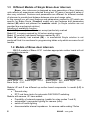
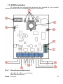
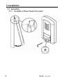
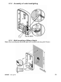
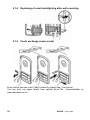
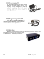
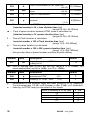
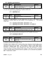
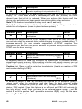
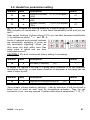
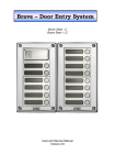
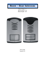
Brave – Door Intercom Brave Smyle - C Brave Smyle - LC Brave Smyle - C/C User guide Version 2.2 Dear customer Congratulation to your purchase of “BRAVE SMYLE door intercom”. The BRAVE Smyle door intercom is designed as universal project to be suitable for different installation on the field and brings more features and possibilities. This manual is designed for Urmet 1129 panel in 4 models with 1 or 2 buttons: Brave Smyle - C - Comfort model Brave Smyle - C/C - Comfort model with analog camera Brave Smyle - LC - Low cost model Basic features of BRAVE door intercoms SMYLE solution – surface installation only IP 44 casing protection LED cards lighting Integrated analog color camera (C/C, LC/C) 1 (2*) relay with 8 different operational modes possibility to use electrical lock PSU for feeding the unit (C) elektronical loudness settings ( without neccessity open the unit) adjustable tones detection for REDIAL or Hanging Up integrated RTC ( realtimeclock) circuit – automatical DAY/NIGHT switching (C) programming by phone DTMF or by USB cable from PC** 24 digits length of number including * # Flash and Pause (C/C, LC/C) – models only * Comfort version only ** USB cabel is an option Version of manual V2.2 Alphatech spol. s r.o. Jeremenkova 88 140 00 Praha 4 Tel/fax: 272103334 22.6.2013 www.alphatech.cz / [email protected] Content 1 BASIC DESCRIPTION ......................................................................................... 6 1.1 1.2 1.3 1.4 1.5 2 FEATURES ........................................................................................................ 6 TERMINOLOGY ................................................................................................. 7 DIFFERENT MODELS OF SMYLE BRAVE DOOR INTERCOM ................................ 8 MODELS OF BRAVE DOOR INTERCOM ............................................................... 8 PCB SCHEMATICS ............................................................................................ 9 INSTALLATION ................................................................................................. 12 2.1 ASSEMBLY ..................................................................................................... 12 2.1.1 Assembly of Brave Smyle front panel ........................................................ 12 2.1.2 Assembly of cards backlighting................................................................. 13 2.1.3 Wall mounting of Brave Smyle .................................................................. 13 2.1.4 Replacing of cards backlighting after wall mounting ............................... 14 2.1.5 Cards exchange (name cards)................................................................... 14 2.2 CONNECTION ................................................................................................. 15 2.2.1 Code relay (COSW) .................................................................................. 16 2.3 CAMERA ( /C VERSION ONLY) ........................................................................ 18 2.4 ACCSSESORIES ............................................................................................... 19 2.4.1 Weather hood 19 2.4.2 TimeRelay 19 2.4.3 DistyBox 19 2.4.4 Power supply 12V ..................................................................................... 20 2.4.5 Programming cable USB .......................................................................... 20 2.4.6 BlackBox 20 3 DOOR INTERCOM SERVICE ......................................................................... 21 3.1 SIGNALLING OVERVIEW ................................................................................. 21 3.2 VISITOR AT THE DOOR .................................................................................... 22 3.3 PERSON INSIDE BUILDING............................................................................... 24 3.3.1 Outgoing call 24 3.3.2 Incoming call 25 3.4 ACOUSTIC PATH SETTING ............................................................................... 25 4 PARAMETRES PROGRAMMING .................................................................. 26 4.1 PROGRAMMING BY PHONE ............................................................................. 26 4.1.1 Programming enter ................................................................................... 26 4.1.2 Parametres programming ......................................................................... 26 4.2 PC PROGRAMMING – BRAVESET PROGRAMM ................................................ 27 5 DESCRIPRION OF PROGRAMMABLE PARAMETRES ............................ 28 5.1 5.2 DIRECT NUMBERS DIAL – MEMORIES .............................................................. 28 RELAY(S) ....................................................................................................... 29 5.3 5.4 5.5 5.6 5.7 5.8 5.9 5.10 6 TECHNICAL PARAMETRES .......................................................................... 51 6.1 6.2 7 BASIC PARAMETRES ....................................................................................... 34 TIME PARAMETRES......................................................................................... 36 SYSTEM PARAMETRES .................................................................................... 39 HANDSFREE PARAMETRES SETTING ............................................................... 41 TIME PROGRAMM – AUTOMATIC DAY/NIGHT SWITCHING (C) ..................... 44 DEFAULT SETTTING AND ERASING ................................................................. 46 PROGRAMMING TERMINATION ....................................................................... 46 PARAMETRES OVERVIEW ............................................................................... 47 ELEKTRICAL PARAMETRES ............................................................................. 51 MECHANICAL DIMENSIONS ............................................................................ 51 TABLE FOR EASY PROGRAMMING ............................................................ 52 BRAVE – user guide 5 1 BASIC DESCRIPTION 1.1 Features Voice communication is powered from telephone line only Tone (DTMF) and pulse dial Two 24digit numbers with each button (including *, #, Flash and Pause) DAY/NIGHT switching by DTMF code or automatically by integrated real time clocks - RTC, weekly schedule (C model) Possibility of the call extension by * or # choice Possibility to connect 1 or 2 (only C) independent locks for door opening 8 different relays modes (for example: additional ring, progressive opening) Two codes for hanging up the unit by telephone Two codes for door opening by telephone for 1 pulse and two codes for 2 pulses 3 x 6 codes for each relay (code by buttons at doors) Can be connected electrically secure lock on the first switch (serial activation code) Possible switched on hang up by press the same push button Possible switched on mode "Baby Call" Possible switched on suppress receive DTMF by microphone Possible switched on accoustic tick to the conversation for speech recognition Possible switched on accoustic signalization of close the relay Adjustable number of rings before pick up an incoming call Adjustable parameters of tone dial, length of Flash and Pause Adjustable parametres of acoustical signalization Adjustable parametres of tones detector Elektronical loudness settings ( without neccessity open the unit) Integrated analog colour camera with permanent or automatical operation /C Automatical camera lighting infra LED /C Possibility of powering by external PSU 12V (Siemens) /C (C) Easy settings of HW by DIP switch Factory settings (default) in different levels Programming by phone DTMF or by USB cable from PC Integrated heating for PCB Permanent cards lighting, switchable Ground output for better protection against static electricity (C) – comfort model only (Comfort) /C - model with camera only 6 BRAVE – user guide 1.2 Terminology Telephone line analog (2 wires) is way of connection to public network (PSTN line) or connection to PABX – telephone exchange at place of installation ( extension line) Line picking up begin of call – same like OFF HOOK by handset Line hanging up end of call – same like ON HOOK by handset Dial DTMF - tone dial. It is dial by 2 tones combination (dial also special character * and #. Use Flash loop interruption) Pulse – dial by loop interruption (dial numbers only) Incoming call connection between intercom and phone has been done by dial from phone.The intercom picks up the call after preprogrammed number of rings. After picking up and password inserting you can programm the unit by phone. Outgoing call connection between intercom and phone has been done by dial from intercom, for example : by button pressing Call establishing it is stage when call is picked up by called party. This stage is not signalled at analog line. It just stop ringing tone and call starts. It is difficult identify just this moment. El.lock code function for relay closing by dial digits combination from intercom buttons Code relay between Doorphone Brave and the electric lock can be connected code relay (COSW - CodeSwitch), which is located at the lock and lock activates only when is the same the specified serial combination of the Brave and set the code on the board relay (COSW). External code Digits combination dial from intercom buttons for relay activation. External = dial by intercom buttons – out of building ( at place of door intercom installation) Internal code Digits combination dial from phone for relay activation (DTMF). Internal = dial by phone – inside building ( phone connected to other PBX extension) The manufacturer continuously improves the product firmware. The technology used allows you to upload to Brave the latest version of the firmware any time using a standard computer with BraveSet and USB cable. The latest version of the firmware is available at http://www.alphatech.cz BRAVE – user guide 7 1.3 Different Models of Smyle Brave door intercom Brave door intercoms is designed as new generation of door intercom units reflects all experiences collected during last 10 years of succesfull sales of door enry solutions. Features and parametres are different for different models of intercom to provide best balance between price and usage value. In this manual you will meet features and parametres marked by (C) which are specific for Brave Smyle (Comfort) model only and features and parametres marked (M) which are planned for modular model (in Smyle solution are not provided due mechanical solution) Labelling of availability function : Model LC (low cost) has all features except particularly marked Model /C is version equiped by full colour analog camera Model C (comfort) has special features marked by (C) Model M (modular) has marked (M) – in mechanical Smyle solution is not produced! And it is mentioned in programming tables only which are same for all models. 1.4 Models of Brave door intercom SMYLE models of Brave LC/C includes appropriate mother board with all connectable elements. Brave Smyle - 01C Brave Smyle - 01C/C Brave Smyle - 01LC Brave Smyle – 02C Brave Smyle – 2C/C Brave Smyle – 02LC Models LC and C are different up mother board components. In model (LC) is missing: Second relay RTC real time clocks for automatic DAY/NIGHT switching Models with camera /C have added: Possibility of external powering (usable for relay modes 7 and 8) automatical / permanent lighting for camera (infra) switch off cards lighting disconnectable internal impedance for camera cable ending 75ohm 8 BRAVE – user guide 1.5 PCB Schematics All functional and connectional elements are marked by red rounded number at bellow picture. Explanation follow on next page. Pict. 1 Brave Smyle mother board (1) + (3) + (7) + (11) - version /C only relay 2 version (C) only BRAVE – user guide 9 1. Camera lighting - infra LED. It lights up space before camera when is active. It is possible switch off (via. item 7) – version for camera only /C 2. Connector to PC connection via USB cable 3. Analog colour camera – version with camera /C only 4. Speaker connection 5. Microphone connection (caution on polarity) 6. DIP switch in all models: 1 = Service, usage – when programming password is forgotton. Incoming call is going directly to programming mode where you can set new password. 2 = Heating – switch ON integrated heating of mother board to increase resistance against condensation water during changes of temperature 7. DIP switch position in versions (C) and /C: 3 = external power supply 4 = external power supply – switching 3 and 4 simultaneously. The powering is used from screw 12V (11) due following reasons: - using relay mode 7 or 8 – tpermanent switching ON/OFF is possible only with external power supply. Dont forget setup parametr 64. - Connection of door intercom to certain type of PBX which has problems with current consumption on its extensions during start (Siemens). 5 = Camera lighting up (switch ON/OFF lighting of space before camera via infra LED) 6 = Cards lighting (switch ON/OFF Leds backlighting for cards beside button) 7 = Activate permanent camera operation. In default camera is active only when door intercom is active. 8 = Allows connect 75ohm to camera output - impedance 8. Analog telephone line (not depends on polarity) 9. Grounding – connection to ground of static electricity protection – protects electronic of door intercom as same as PBX 10. Relays are galvanically isolated - max. 48V, max. 1,5A model (C) has 2 relays model (LC) has 1 relay only on switch 1 is available relay function code (COSW - CodeSwitch) (see page16) 11. Camera output - PAL video 1V / 75ohm. For distance longer than 25m we recommend coax cable. For other installation UTP cable is also available. /C model only 12. 12V power supply: - relays control - mother board heating - cards backlighting - camera powering and infra LED camera lighting up - external powering of unit (DIP 3 and 4) The power supply might be AC as same as DC, not depends on polarity, max consumption 250mA from 12V. The power supply might be used also for electrical lock powering. Then we recommend power supply 12V/1A. 10 BRAVE – user guide You can also use 24V DC power supply. It is useful mainly at installations where power supply is already installed and it is used for sliding doors, RFID, etc.. The heating has control element to restrict power. The remaining components are designed for voltage up 24V DC!!! It not depends on polarity. BRAVE – user guide 11 2 Installation 2.1 Assembly 2.1.1 12 Assembly of Brave Smyle front panel BRAVE – user guide 2.1.2 Assembly of cards backlighting 2.1.3 Wall mounting of Brave Smyle Make the mounting by attached pack with screws and plug (drill 5mm). BRAVE – user guide 13 2.1.4 Replacing of cards backlighting after wall mounting 2.1.5 Cards exchange (name cards) Every button has own card ( label) holded by plastic flag ( via picture). You can print out paper labels from special Excel file (downloadable on www.alphatech.cz or ). 14 BRAVE – user guide 2.2 Connection The basic functionality of intercom (voice communication) needs connection of telephone line only - LINE (8) on .Pict. 1 Brave Smyle. The line is connected by 2 wires (a,b) and in stand by has usually voltage 24V - 60V, short circuit current 20mA - 60mA. When line is OFF HOOK the line voltage is 7V - 10V. Line connection Brave Smyle intercom announce by sound signal (Reset) ♫ (capture 3.1 page.21) when is disconnected from line certain time. Brave Smyle is analog intercom designed for connection to analog line( PSTN line or PBX analog extension) it means line where works ordinary analog phone. It works regardless to line polarity and in range mentioned in technical parametres (capture 6). Paralel connection – we not recommend! Paralell connection with other analog phone or other door intercom is not recommended! We also not recommend use special devices switching the line ( inteligent couplers, adapters, etc..). When model of Brave Smyle is with camera /C then on screw CAM (11) on Pict. 1. connect cable for video transmission. Up to 25m you can use one free pair of UTP cable. For longer distances you have to use coax cable Pict. 1. Camera mode you setup by DIP switch (capture 1.5) and camera is either activated automatically (when intercom is active) or is permanently ON (DIP 7). Camera lighting up by infra LED is either active with camera (DIP 5) or you can permanently switch OFF. Due DIP 8 you can paralelly connect to video output impedance 75ohm 12V power supply (12) on Pict. 1 must be connected for mother board heating, cards backlighting, camera powering inludes infra LEDs and for relays control. The power supply might be AC and also DC, not depends on polarity. From 12V is max consumption 250mA. Power supply might be used also for electrical lock powering. Then we recommend power supply 12V/1A. You can also use 24V DC power supply. It is useful mainly at installations where power supply is already installed and it is used for sliding doors, RFID, etc.. You can use only 24DC power supply not AC!!! Not depends on polarity. Relays (10) on Pict. 1 have many possibilities in practise usage. The examples (drawings) are mentioned on Pict. 2. 12V power supply must be connected for correct operation. The intercom unit has galvanically isolated all important parts. Telephone line is isolated from power supply and relays contacts are also galvanically isolated from other intercom electronic parts. In any case must not be activated directly main voltage 120V or 230V !!! When you need control main devices please use contactors ( power relays) as it is on Pict. 2 example (6) . BRAVE – user guide 15 Relays connection examples are mentiond on following page. It is not all of them but give you an idea how should be connected individual circuits (red rings with numbers = example numbers). 1. Basic connection - 2 elektrical locks and possibility independently control two doors. (relay mode 1 and 2 m=1) or progressive door opening (relay mode 2 m=5 - version (C) only. 2. Two power supply – possibility to use independently two power supply One for Brave Smyle and second for electrical locks. Second electrical lock is connected inversaly (fire emergency exit). 3. Combination of doors with electrical lock and sliding gate at fencing. 4. Extending of previous example (3) about second doors with progressive opening (this feature is setup in TimeRelay - optional modul) 5. Combination of electrical lock and additional ring. Relay of additional ring might be in mode m=4 (from each button is activated for preprogrammed time) or in mode m=6 (it is activated from one presetup button for preprogrammed time) 6. Lighting activation m=3 (for example: way to building ) and control of for example: heating up DAY/NIGHT mode m=8 ( (C) version only - RTC circuit). External power supply required (DIP 3 and 4) /C version only. Further is neccessary use contactor (Brave Smyle must not activate 230V!). 2.2.1 Code relay (COSW) For the first switch is available function code relay (COSW CodeSwitch). It serves primarily to secure transmission of information by switching the electric lock. When using this function is not possible connecting or disconnecting the voltage at the terminals to lock this lock activated. Activation is performed only when positive result compared serial information transmitted between Brave and the board code relay Brave is set in several codes to activate the relay code. Relay can be activated codes for one or two impulses can differentiate activated from the phone (DTMF) or from keys (keyboard). The last option is the activation code in another mode switch than the lock. The code information is 8 bits, but the code is 4 bits with security 4 bits which is total of 8 bits. Practically, this is performed so that after activation the switch is first transmits the serial code, and if they agree, so code relay connects the electric lock. The code relays can be connected in parallel to increase the number of switches, but can never combine connections electric lock and the code relay parallel! 16 BRAVE – user guide Pict. 2 Examples of relay connection BRAVE – user guide 17 2.3 Camera ( /C version only) Technical parametres: - videonorm: - sensor: - picture area: - resolution: - video output: - automatic profit control: - minimal lighting: - automatic lens shutter: - camera view: - zoom: 18 PAL-CCIR CMOS 1/3'' 5,78x4,19mm 628x582pixel 380 rows 1V p-p/75 ohm 18dB 3LUX 1/60-1/15000sekund 50st. manually BRAVE – user guide 2.4 Accssesories 2.4.1 Weather hood It increases intercom protection during raining. It is fixed by adhesive labels from sides. 2.4.2 TimeRelay Time relay allows expansion of relays functionality. It is individual product and detail manual you find on our websites www.alphatech.cz 2.4.3 DistyBox This optional modul is plastic box allows you to connect analog unit (phone, intercom) into wireless system DECT – GAP (for example Siemens line GigaSet, TopCom line Butler etc.). DistyBox is suitable for intercom connection when are cables not available. You just registrate intercom as handset to DECT base station. All features of intercom are kept. Important: DECT base station must support DTMF transmission between each handsets (relay activation feature). BRAVE – user guide 19 2.4.4 Power supply 12V As standard we provide for Brave Smyle intercom AC power supply 12V/1A . It is not part of unit packaging. It must be ordered individualy. More info about electrical locks and power supply on www.alphatech.cz. 2.4.5 Programming cable USB USB cable is not part of packaging. It must be ordered individualy. USB drivers are downloadable on www.alphatech.cz 2.4.6 BlackBox BlackBox is DTMF modem useful for remote programming from PC. Via BraveSet programm you can remotely setup all parametres of Brave Smyle intercom. 20 BRAVE – user guide 3 Door intercom service Functionality of Brave Smyle door inercom is adjustable by parametres settings (via. Programming parametres capture page 26). 3.1 Signalling overview The Brave Smyle door intercom signalling acoustically stages which are happening during operation. Samples of acoustical sounds you can play in BraveSet ( PC programm). Stage Tones Tone frequency Line pick up ( OFF HOOK) type 1 –▄▔▄▔▀– 980-1333-1650 Line hang up ( ON HOOK) type1 –▀▔▄▔▄– 1650-1333-980 Line pick up ( OFF HOOK) type 2 –▄▔▀– 800-1067-1200-1333 Line hang up ( ON HOOK) type2 –▀▔▄– 1333-1200-1067-800 Command confirmation by phone ––█–– 800 Alerting (knocking) into call ─┴─┴─ Call ending alert –▔–▔–▔– 1333 ─▒▒▒▒▒▒─ Modulovaný –▄▔▀– 980-1067-1180 Programming by phone ––▓–▓––––– Modulovaný Parametr confirmation ––█–– 800 Programming enter by PC –▄▔▀– 980-1067-1180 –▔–▄–▔– 1850-1067-1850 –▔–▔–▔–▔–▔–▔– 800 –▄▔▄▔▄▔▄▔– 1300-2100 Relay activation signal Programming enter by phone Line connection (Reset) Error (generally all incorrects) Memory empty (no number programmed) During problems identification is very good when you know the tones. It helps you monitor how door intercom works and where from comes the problem. The signalling might be switch of in a few levels (parametres 61,62,63 and 65). BRAVE – user guide 21 3.2 Visitor at the door Door intercom buttons have signs (cards) like usual ring buttons. Visitor find desired name (for example“Scott") and push it. The Brave intercom pick up the line and "play" tone line pick up (when is not switch off by par.62) and dial phone number saved under the button (parametr 1 or 2 up door intercom mode). From Brave intercom speaker you hear ringing tone and phone of Mr. Scott is ringing. As soon as Mr. Scott pick up ringing phone he can talk to visitor at the door. When is electrical lock connected to Brave intercom then Mr. Scott can open the door for visitor by dial DTMF code on his phone. When Mr. Scott hang up the phone then Brave intercom hangs up as well after busy tone detection. When call duration is longer then setup limit (parametr 52) the 10sec before hang up Brave intercom sends alerting tone of call ending. Mr. Scott can dial * or # up setting (parametr 42) to prolong the call about the time setup by parametr 52. Dialled number from Brave intercom is different up dial mode setup in the unit by (parametr 47): - Day/Night mode = when intercom is in DAY mode then number setup by parametru 1 is dialled. When intercom is in NIGHT mode then always dial number setup by parametr 2. Manual intercom modes switching is setup by parametres 45,46. In version (C) you can switch DAY/NIGHT mode automatically. Selection of dialled number saved under the button is control by time up table (parametry 00-06). - 2 groups numbers mode = first button push – always dial number setup by parametr 1. When the same button is pushed or 10seconds after dial busy tone is detected, or setup number of rings is out (parametr 56) the door intercom dial number from second group setup by (parametr 2). When you push the same button again you will dial again number from first group etc.……(when after dial number from second group busy tone is detected the repeating is finished) When visitor push the button after line is picked up the door intercom hangs up for time setup by parametr 54 and then picks up the line and dial new number ( second push number). The number dialling is either by tone dial (DTMF) or pulse dial up setting by parametr 41. There is one more option and it is line hangs up by again pushing of same button (parametr 4*). You can control relay(s) by door intercom buttons (code lock). When visitor push buttons in order which match to setup code (parametr 32-34) and time between each button press is not longer than setup by (parametr 53) then door intercom picks up and activate appropriate relay (when relay setup is mode m=1 or m=5) for time setup by parametr 37 eventually.39,30. Then hangs up. The relay (up control code) can activate one pulse or two pulses with time between each pulse setup by parametr 30 via. Tab. 1. 22 BRAVE – user guide mode m = 1 Action Evaluation of correct external code from buttons (parametr 3111 and 3121) Note According settings DAY/NIGHT According settings DAY/NIGHT According settings DAY/NIGHT According settins DAY/NIGHT Internal code from phone Parametr Relay 3211-3215 3311-3315 3411-3415 3221-3225 3321-3325 3421-3425 321* 331* 341* 322* 332* 342* 351 You can dial 1 or 2 numbers of code 2digits code is default You can shorter it by using * on first digit of code during programming 352 361 362 Mode m = 5 Action Evaluation of correct external code from buttons (parametr 3125) Note According settings DAY/NIGHT According settings DAY/NIGHT According settings DAY/NIGHT According settings DAY/NIGHT Internal code from phone BRAVE – user guide You can dial 1 or 2 numbers of code 2digits code is default You can shorter it by using * on first digit of code during programming Parametr Relay 3211-3215 3311-3315 3411-3415 3221-3225 3321-3325 3421-3425 321* 331* 341* 322* 332* 342* 351 352 361 362 23 mode m = 4 Action Note Button push Parametr Relay 3114 Any button different from 311* or 312* 3124 3114 Button setup by 311* or 312* 3124 Mode m = 6 Action Button push Note Any button different from 311* or 312* Parametr Relay 3116 - 3126 - 3116 Button setup by 311* or 312* 3126 Poznámka: t1 – time activation 1 of relay (parametr 371) t2 – time between pulses 1 of relay (parametr 301) t3 – time between activation 1 and 2 relay (parametr 39) t4 – time activation 2 of relay (parametr 372) t5 – time between pulses 1 of relay (parametr 302) Tab. 1 Table of relay(s) control 3.3 Person inside building By person inside building we mean person in telephone connection with Brave intercom , for example Mr. Scott. 3.3.1 Outgoing call Outgoing call is a call from door intercom (generated by visitor). After door intercom dial is ringing a phone inside the building. When you pick up the phone you can talk to visitor. By code dialling you can activate the relay (parametr 35) when relay is setup in mode m=1 or m=5. You also can switch operation mode DAY/NIGHT (parametr 45,46) and hang up (parametr 43). Door intercom sends 10sec before call ending (parametr 52) alerting tone and you can prolong the call by dialling special character from phone (parametr 42). By phone hanging up the call is ended (PBX generates busy tone into the line which is detected and door intercom hangs up). There is one more option which is hang up the line by again push of the same button (parametr 4*). 24 BRAVE – user guide 3.3.2 Incoming call Incoming call is a call into door intercom (generated by person inside the building). After dialling extension number where is connected door intercom the door interocm line is ringing. After setup number of rings the door intercom picks up (parametr 51) and you can talk. Other possibilities are the same like in case of outgoing call (capture 3.3.1). First exception is first 10sec where you can dial "# and service password" (parametr 44). By this you enter programming mode of door intercom. Second exception is when DIP1 is switch to position ("SERVIS"). Then you enter programming mode directly without dialling service password. Last exception is relay(s) control (parametr 381 and 382). You can by programming prohibit to control relay(s) from incoming call . 3.4 Acoustic path setting The principle of setting acoustic paths: Here we have three parameters 71.72 and 73 Using the interaction of these parameters can be set to sound in different conditions. 1. quiet environment parameters 71,72,73 are set to 7 2. environment where is a strong ambient noise at the communicator and quiet environment at the phone. Here is both necessary to reduce the microphone gain (parameter 72 = 1-3) and also change the ratio of the parameters 71/73 way 73 enlarge the the parameter (parameter 73 = 11-15) and 71 parameter smaller value (71 = 2-4) 3. environment where is a strong ambient noise at the phone and quiet environment at the communicator. Here we leave the parameter value of 72 = 7 and 73 and 71 parameters set as follows - parameter71 = 11 to 14 and 73 = 2 to 4 The principle of settin parameters is - signal from the microphone is amplified by the sum of parameters 72+71 = volume of microphone and signal to the speaker is amplified by the sum of parameters 71+73 = volume of speaker. To switch the direction of the ratio is evaluated parameters (threshold) 73/72. - If parameter 72 is greater than the parameter 73, thus favoring the direction from the microphone. We choose when the direction to the phone is interrupted. - If parameter 73 greater than parameter 72, thus favored direction to the speaker. We choose this if the interrupted sound in the speaker of communicator. BRAVE – user guide 25 4 Parametres programming 4.1 Programming by phone 4.1.1 Programming enter You can enter programming mode by following ways: 1. password – incoming call only! – pick up the phone and dial phone number where is door intercom connected (either extension number when door intercom is connected to PBX or PSTN line number of building where is door intercom installed and let operator connect you to appropriate door intercom extension). Door intercom picks up (you hear pick up acoustic tone – via. capture 3.1 page.21) and you have to dial within 10 sec #xxxx, when xxxx is service passsword to enter programming mode (default xxxx=0000). When all is correct you hear acoustic tone of programming mode enter and after a while you hear programming tone (via. capture 3.1 page.21). 2. switch "SERVIS" – incoming call only! – the connection you establish the same way like in item 1. but only when DIP1 switch is in position "on". Then door intercom after picks up going directly into programming mode without neccessity to insert service password. (via. capture 3.1 page.21). 4.1.2 Parametres programming Stand by stage of programming is announced by programming tone into which door intercom always returns after time out (5sec) whenever you started to programm. There are two kind of parametres you can programm. First are parametres with fix length – Most of parametres are those. The parametr is saved immediatelly after inserting mandatory length – you hear confirmation tone. Second are parametres with variable length (parametr 1, 2,32,33,34). Saving and confirmation of those parametres is made after 5 seconds inserting last dial. There is one case when those parametres are saved immediately and it is filling up maximal number of characters (numbers) – at parametr 1 and 2 it is 24, parametr 32,33,34 it is 6. When during programming insert number(character) which is unacceptable then door intercom sends error tone. The parametr is not saved even changed. Door intercom returns to stand by and you can start again parametr programming of programm other parametr. When you enter programming mode and do not make any dialling for 30seconds the door intercom will hang up. After each dialled DTMF tone the time is prolonged about 30seconds. You can finish programming mode also by dialling parametr 9. 26 BRAVE – user guide 4.2 PC programming – BraveSet programm For PC programming of door intercom you have to purchase special USB cable USB-KAB and programm BraveSet ( free on every CD). Then you have to connect door intercom into the line or at version /C or (C) switched ON and connected power supply 12V - DIP3 and 4. Procedure: - Connect telephone line into door intercom or at version /C and (C) you can use external power supply 12V (DIP 3,4) - Connect special USB cable to PC USB socket . Door interocm picks up the line within 3 seconds and play tone of programming enter (via. capture capture 3.1 page.21). - Run programm BraveSet. Door intercom is in programming mode during all the time when programm BraveSet is running. The door intercom stays pasive until moment of USB cable disconnection. When you loose connection please disconnect USB cable from door intercom and connect it again – door intercom picks up. - Correct connection PC with BraveSet programm is indicated by reading firmware version from door intercom ( visible in bar) as same as reading the time ( shown in left top corner). When you have version (LC) then time is 0 because LC version doesnt includes RTC circuit. For easy orientation are parametres in BraveSet programm marked by the same codes like codes for programming by phone. Details about setting you will find in programm HELP and on website www.alphatech.cz. USB cable is special cable with galvanical isolation and with 3V convertor. The galvanical isolation is neccessary because telephone line must not be grounded and PC´s are usually grounded. BRAVE – user guide 27 5 Descriprion of programmable parametres Parametres always starts by fix, mandatory part ( adress) and variable part – it is your dial. Range and explanation is always under each table . All is dial like it is written in table. You dont dial any confirmation character. After savings into memory you get back confirmation tone. When dialled value is incorrect you get immediatelly error tone. 5.1 Direct numbers dial – memories Parametr 1 Value tt nn… description Default Number nn under button tt - tt – button number (memory), always has 2 digits [01-99] nn – phone number up 24 digits which you desire to save. For saving further characters use assignments mentioned in table. Numbers saved in parametr 1 are numbers of first group, or numbers of DAY mode. Default settings doesnt erase as same as changed those saved numbers. Parametr 2 Value tt nn… Description description 0-9 # * Flash Pause dial 0-9 # ** *# *0 Default číslo nn pod tlačítkem tt - tt – button number (memory), always has 2 digits [01-99] nn – phone number up 24 digits which you desire to save. For saving further characters use description 0-9 assignments mentioned in table. # Numbers saved in parametr 1 are numbers of second group, or numbers of NIGHT mode. * Default settings doesnt erase as same as changed those Flash saved numbers. Pause Dial 0-9 # ** *# *0 Note: switching DAY/NIGHT mode stays in door intercom even after line disconnection and version (C) this mode switch up current time (when this feature is activated parametr 084) Note: at version Brave Smyle - C and Brave Smyle - LC are available max. 2 buttons tt=01-02 28 BRAVE – user guide Settings examples: 1. first button should dial at DAY number 358 and in NIGHT 0_603441296 , you programm it - 101358 and wait for ♫, next 2010 *0 603441296 and wait for ♫ 2. second button should dial at DAY and NIGHT 123#1*2Flash3, you programm 102123#1 ** 2 *# 3 and wait for ♫, next 202123#1 ** 2 *# 3 and wait for ♫ Note. When you dont use mode of 2 group numbers or DAY/NIGHT mode we recommend setup DAY/NIGHT mode (parametr 47) and next setup same code for DAY/NIGHT switching (parametry 45 and 46). You provide by this that door intercom will be always in DAY mode and then you programm numbers for DAY mode only (parametr 1). 5.2 Relay(s) Parametr 31 Value rm Description relay r works in mode m Deafault (1-8) 11 21 r – relay number [1-2] m – relay mode [1-8 for r=1 is not mode m=5] modes m=1,4,5,6 are detaily descriped in Tab. 1. on page 24 m=1 mode relay – activated by command (internal code) or password (external code) 1 pulse for time t1/t4 (using for electrical locks) or 2 pulses when is activated for time t1/t4, open for time t2/t5 and close for time t1/t4 (sliding door opening) m=2 closed for time of line OFF HOOK (camera) – close when door intercom picks up and open by hanging up m=3 closed for time of line OFF HOOK and more for time t1/t4 after hang up (lighting) – closed when door intercom picks up and stays closed for time t1/t4 after door intercom hangs up (for this time line is busy, at version /C and C is after switching DIP 3,4 and settings parametr 64 for time t1/t4 line hanged up) m=4 mode button – closed when any button is pushed and open after time t1/t4 (usage for example: connection external bell) m=5 mode progressive opening – you can setup into this mode relay 2 only because relay 1 will be setup automatically into mode m=1. By command (internal code) or password (external code) is activated relay 1 for time t1, then is running time t3 before closing relay 2. Then is relay 2 activated for time t4 and then door intercom hangs up. When dialled command or password match to 2 pulses then in sequence will appear two pulses separated by time t2/t5. Explained in Tab. 1 Note. The command or password for relay 1start whole sequence.When you use command or password for relay 2 then you control relay 2 only the same like in mode m=1. m=6 closed up pushed button (setup in parametr 31r*). Due this you can select one button for every relay its pushing activate appropriate relay for time t1/t4. This mode serves as substitution of ring bell connected to Brave system. BRAVE – user guide 29 m=7 permanent closing / opening – usable at versions /C and (C) only, if switching (DIP 3,4)+par.64. By command for pulse 1 is closed and for pulses2 is opened. This stage stays in door intercom even after power/line disconnection. This mode you can use for potting, glasshouse opening, heating activation etc.. m=8 activated up DAY/NIGHT mode settings - usable at versions /C and (C) only, if switching (DIP 3,4)+par.64. Version /C allows copying manual DAY/NIGHT switching only. Version (C) allows copying setting from week table switching time (when is activated - parametr 084) and then you can use for example for heating control etc… Parametr 31 Value r* tt Description Default button tt start relay closing r in mode m=6 (01-99) 01 r – relay number [1-2] tt – button number (memory), always has 2 digits [01-99] This parametr is for relay mode m=6 only. Value of tt designate from which button start closing for time t1/t4 of relay r. Parametr Value 32 rp hh... 33 rp hh... 34 rp hh... Description Default In mode DAY + NIGHT password hh... for relay r, in order p=1-5, for 1 pulse and p=* for 2 pulses (00-999999) In mode DAY password hh... for relay r, in order p=1-5, for 1 pulse and p=* for 2 pulses (00-999999) In mode NIGHT password hh... for relay r, in order p=1-5, for 1 pulse and p=* for 2 pulses (00-999999) - – relay number [1-2] – order [1 - 5] for 1 pulse. 5 passswords (external codes) from door intercom buttons (external code of codelock) p – order = *, then you can insert just one code (external code) for closing by 2 pulses hh... – password (external code) for relay closing from buttons [2 to 6 digits]. Tlačítka 1 - 10 are programmable as numbers 1-0. Totally 3 x 12 passwords. Controlled by settings DAY/NIGHT. Combination is inserting by door intercom buttons. Relay closing is influenced by setup relay mode and switching DAY/NIGHT. When is setup mode 2 groups of numbers the door intercom is permanently in mode DAY. You have to keep certain rules for password dialling: First button of password select from at least used button for direct dialling (-prolong dial time) r p 30 BRAVE – user guide Caution on numbers identity of password. When one password includes other, for example:password for relay1 is 1234 and for relay 2 12345, then always after pushing button 4 relay 1 will be activated and relay 2 wont be never acivated. When you select password for relay 2 234, then after button 4 pushing both relays will be activated. Note1. switching to DAY/NIGHT mode stays setup in door intercom even after power (line) disconnection. At version (C), when is activated, then DAY/NIGHT switching is done up time and week table. Note2. when you insert parametres 32,33,34 do not use character # and * because you cant select them from button panel. Number 0 represents button 10. Parametr 35 Value r aa Description command aa from phone for relay activating r 1 pulse (00-99,*0-*9) Default 155 266 r – relay number [1-2] 1 aa – command (internal code) from phone for relay activation [2 digits] / For both relays you can setup the same command (internal code) then both relays are activated simultaneously. It is profitable to setup the same command for relay activation as same as door intercom hang up (parametr 43) aa=bb. 1 / – command has always 2 digits but when you want control relay by 1 digit only ( from keypad of phone) then you have possibility to programm " *a " where a is one number only which activate the relay (star represents empty character and must be on first digit position). Example: 1 relay activated by internal code 48 - dial 35148 ♫ 2 relay activated by internal code 8 - dial 352*8 ♫ By dialling on phone 8 you activate relay 2 by dialling 48 you activate both relays Parametr 36 Value r cc Description command aa from phone for relay activation r 2 pulses (00-99,*0-*9) Default 150 260 r – relay number [1-2] 1 cc – command (internal code) from phone for relay activation [2 digits] / For both relays you can setup the same command (internal code) then both relays are activated simultaneously. 1 / – command has always 2 digits but when you want control relay by 1 digit only ( from keypad of phone) then you have possibility to programm " *a " where a is one number only which activate the relay (star represents empty character and must be on first digit position). Activation relay 2 pulses is suitable for example: at sliding gate which this way can also substitute wicket for person entrance. BRAVE – user guide 31 Example: command to activate relay1 with 1 pulse *8, command to hang up *8 and command for activation relay2 with 2 pulses *9. Dial: 352*8 ♫ , 432*8 ♫ , 362*9 ♫. You are in communication with door intercom unit. Dial command for open sliding gate 9. First pulse starts sliding the gate and second pulse stop it. The size of spot for person entrance is according time between each pulses (parametr 30). After person etnering you dial 8. The door intercom makes one pulse and hang up. Sliding gate is closing. Parametr 37 Value r ss Description Default time ss [sec] activation relay r for time t1/t4 (00-99) 105 205 r – relay number [1-2] ss – time t1 / t4 for which is relay closed 1 / 2 [2 digits 00-99], where time 00 means 0,5sec Parametr 38 Value rp Description Default Control relay r during incoming call (0/1) 11 21 r – relay number [1-2] p – parametr which says permitted p=1 or forbidden p=0 control relay during incoming call To prohibit control of relay during incoming call has a sense for example by relay2 in mode 1 by which you control sliding gate opening where door intercom open the gate and after car passing the gate is closed. Then control by phone could make unwillingly permanent gate opening. Parametr 39 Value xx Description Default time xx [sec] between activation relay 1 and 2 in mode m=5 - time t3 (01-99) 10 xx – time t3 between activation relay 1 and 2 when mode m=5 is setup (progressive opening) [2 digits 00-99] ], when time 00 means 0,5sec Parametr 30 Value r zz Description Default time zz [sec] between pulses when is closing for 2 pulses relay r - time t2/t5 (00-99) 105 205 r – relay number [1-2] zz – time t2 / t5 between first and second pulse relay activation 1 / 2 [2 digits 00-99], where 00 means 0,5sec 32 BRAVE – user guide Parametr Value 3#0 p Description p = 1 enabled / disabled p = 0 connection code relay COSW (0/1) Default 0 p – turns on transmission serial code to activate the first switch. CAUTION - at activation this function never connect to the circuit electric lock without board COSW - code relay - threatens to destroy the relay in Brave communicator! The following codes may be the same or different for the resolution switching on multiple parallel connected relay code. Parametr 3#1 abcd – Parametr 3#2 abcd – Parametr 3#3 abcd – Parametr 3#4 abcd – Parametr 3#5 abcd – Value abcd Description activation code 1 pulse from buttons (0000-1111) Default 0000 Brave sends a serial code for the code relay (COSW) after evaluation code from keys (keyboard) namely for 1 pulse Value abcd Description activation code 1 pulse from phone (0000-1111) Default 0000 Brave sends a serial code for the code relay (COSW) after evaluation code from telephone (DTMF) namely for 1 pulse Value abcd Description activation code 2 pulses from buttons (0000-1111) Default 0000 Brave sends a serial code for the code relay (COSW) after evaluation code from keys (keyboard) namely for 2 pulses Value abcd Description activation code 2 pulses from phone (0000-1111) Default 0000 Brave sends a serial code for the code relay (COSW) after evaluation code from telephone (DTMF) namely for 2 pulses Value abcd Description activation code from other modes of switch (0000-1111) Default 0000 Brave sends a serial code for the code relay (COSW) after evaluation code from other modes m switch 1 BRAVE – user guide 33 5.3 Basic parametres Parametr 41 Value v Description Dial type v – tone / pulse Default 0 (0/1) v – dial type v=0 is DTMF tone dial, v=1 pulse dial Parametr 42 Value z Description Character to prolong the call Default * (* / #) z – character to prolong the call * or # (10sec before call termination door intercom sends notification then you can prolong the call) Parametr 43 Value g bb Description Default Command to hang up door intercom by phone (00-99,*0-*9) 155 266 g – command order [1-2] (they are two to be possibility hang up door intercom when each relay is used) 1 bb – command to hang up door intercom by phone [2 digits] / It is profitable setup the same command to hang up door intercom as same as activate relay (parametr 35,36) aa=bb or aa=cc 1 / – command has always 2 digits but if you want use 1 digit then you have possibility insert " *a " where a is just one number which activate the relay (star represents empty character and must be on first position). (Example at parametres 35,36) Parametr 44 Value xxxx Description Service password Default (0000-9999) xxxx – service password to enter programming by phone (DTMF) 34 BRAVE – user guide 0000 Parametr Value 45 dd 46 nn Description Default Command to switch into DAY mode (00-99,*0-*9) Command to switch into NIGHT mode (0099,*0-*9) 11 10 1 dd – command to switch into DAY mode [2 digits] / 1 nn – command to switch into NIGHT mode [2 digits] / 1 / - command has always 2 digits but if you want use 1 digit then you have possibility insert " *a " where a is just one number which switch DAY/NIGHT mode (star represents empty character and must be on first position). Note. Switching into DAY or NIGHT mode stays setup even after power (line) disconnection from door intercom Parametr Value 47 e Description Door intercom dial mode Default (0/1) 1 e – dial numbers mode e=0 dial numbers from first and second group, e=1 numbers are dialled up DAY/NIGHT mode in door intercom CAUTION !! setting of this parametr has a big influence to numbers dialling Parametr Value 4* k Description Feature of line hanging up by again push of the same button (0/1) Default 1 k – line hanging up by push of same button: k=0 feature is switch off k=1 again button push hang up the line CAUTION !! setting of this parametr has a big influence to numbers dialling BRAVE – user guide 35 5.4 Time parametres Parametr 51 Value q Description Default Number of rings before door intercom picks up incoming call (1-9) 2 q – number of incoming call rings . Door intercom picks up between rings and 2 sec after detection of q – th rings. Number is adjustable from 1 to 9. Parametr 52 Value d Description Maximal call duration Default d – maximal time for which door intercom is OFF HOOK. This time you can prolong by dial character during a call by phone (* or # - parametr 42). Setting of time is up table. Parametr 53 Value w time[min] 0,5 1-9 15 30 Description Time between button push 2 (0-9,*,#) Dial 0 1-9 * # Default (1-9) 2 w – maximal time [sec] between button push [range 1-9] normal buttons - relay activation – when time between push of 2 following buttons is longer than time w then code is evaluated incorrectly. - Number dial – when button which we push is first number in password for relay activation then dial is delayed about this time w 36 BRAVE – user guide Parametr 54 Value z Description Hanging up time during REDIAL Default 2 (1-5) z – time [sec] for which door intercom hangs up before pick up for REDIAL (button push during call, busy tone detection) [range 1-5] Parametr 55 Value z Description Time before start dialling Default 1 (1-5) z – time [sec] after door intercom picks up and before start dialling [range 1-5]. This time is different for every PBX but usually all PBXs accepts dial within 2 seconds after line is picked up. Parametr 56 Value hh Description Number of rings before hang up Default 12 (04-99) h – after dial termination calculate number of CRT (control ring tones). When number is higher than hh then hang up [range 04-99]. Dial is repeated in case of 2 groups mode. Parametr Value Description Default 3 (375-475Hz) 500 x Middle frequency of tones detector (1-0) 501 y Number of busy tones (2-0) 4 502 z Time of permanent tone duration (1-5) 3 (3s) x – middle frequency of tones detector – is suitable when PBX signalling is unusual: frequency x - dial y – minimal number of busy tones neccessary for detection [2-0], where 0 means 10 busy tones z – minimal time of permanent tone duration (for dial tone detection on PBX) [1-5 sec] Parametr Value BRAVE – user guide Description [Hz] 275-375 325-425 375-475 425-525 475-575 525-625 575-675 625-725 675-775 725-825 1 2 3 4 5 6 7 8 9 0 Default 37 Time of tone duration DTMF (tone) dial (04-16) Time of space duration between DTMF tones (04-16) 503 tt 504 mm 505 f Time of Flash duration 506 p Time of pause duration / pause between numbers (1-0) (1-6) 10 (100ms) 10 (100ms) 1 (100ms) 4 (800ms) –Time of tone duration DTMF (tone) dial is calculated up: (inserted number) x 10 = tone duration time [ms] [range 04-16 tj. 40-160ms] m – Time of space duration between DTMF tones is calculated up: (inserted number) x 10 =pause duration time [ms] [range 04-16 tj. 40-160ms] f – Time of Flash duration is calculated: inserted number x 100 = Flash duration time [ms] [range 1-6 tj. 100-600ms] p – Time of pause duration is calculated: inserted number x 100 + 400 = pause duration time [ms] [range 1-0 tj. 500-1400ms] – time p is also time of pause between numbers at pulse dialling tt Parametr 507 Value uu Description Default Level of sending tone DTMF dial in [-dBm](04-16) 10 uu – level of sending tone (DTMF) dial into line, range is -4 to -16dBm. You insert desired level, uu=04 is -4dBm, uu=10 is -10dBm Parametr Value Description Default 508 p preemphase DTMF (0/1) 0 509 S Listening –in DTMF - level (1-4) 2 p – preemphase is rate between upper and lower groups of DTMF frequency. You can select rate 2,2 dB - p=0 (Europe) or rate 3,2dB - p=1 (Australia) s – listening –in DTMF level you can select in four levels: Level of listening in DTMF [dB] s - dial -15 1 -9 2 -3 3 +3 4 38 BRAVE – user guide 5.5 System parametres Parametr 61 Value z Description Acoustic signalling (confirmation, error, empty memory, call termination...) (0/1) Default 1 In default the stages of door intercom are acoustically signalling. By parametr „z“ you can switch off this signalling. Possible values are z=0 – signalling is off z=1 – signalling is on Parametr 62 Value v Description Acoustic signalling off hook/on hook (0/1/2) Default 1 In default is signalling pick up and hang up of the line. If you identify some problems at certain PBXs you can switch it off by parametr „v“ . The possible values are: v=0 – signalling OFF HOOK / ON HOOK is off v=1 – signalling OFF HOOK / ON HOOK is on (type 1) v=1 – signalling OFF HOOK / ON HOOK is on (type 2) Parametr 63 Value u Description Acoustic signalling knocking to call (0/1) Default 0 In default it is switch off. By activation of this feature you can identify at PBX calling from door intercom just up knocking into call. Possible values are: u=0 – knocking to call is off u=1 – knocking to call is on Parametr 64 Value w Description Powering from external power supply 12V (DIP 3,4) (0/1) Default 0 In version /C only or at version (C) . In default external power supply is OFF. Activation has a sense only in cases when door intercom should make some operation during stand by mode – relay activation. Relay in mode m=7 allows permanent closing even after call termination. Relay mode m=8 allows activation up DAY/NIGHT mode settings even after call termination. In those cases you have to provide external power supply to dont flow current at hanged up line. The DIP switch 3 and 4 must be in position „on“ to activate this parametr w=1 . Deactivation - w=0. BRAVE – user guide 39 Parametr 65 Value z description Default 0 Acustic signalling of relay activation (0/1) In default the activation is off z=0. Usually you can use this fetaure for DC power supply 12V. Then when el.lock is released you dont hear „buzzing“ so visitor doesnt know that el.lock is released. When you activate this feature z=1 then during relay activation you hear special sounds simulating relay activation. Note.1 This feature is available for relay mode m=1, m=5 only. Note.2 For relay activation with 2 pulses the acoustic signalling sounds during whole time of sequence. (even in space between pulses) Parametr 66 Value i Description Default Suppression of DTMF reception from microphone (0/1) 0 In default the suppression of DTMF reception from MIC is off i=0. Due this you can activate relay by personal dialler without ringing to person inside building. To increase security you can activate suppression of DTMF reception from microphone i=1 and due this protect entrance of persons who provided record of DTMF code for door opening. Parametr 67 Value b Description Default BabyCall – call without neccessity programm phone number (0/1) 0 In default is switch off b=0. By activation this feature b=1 is cancelled acoustic signalling of empty memory. After pushing of button with empty memory you get just beep (confirmation) and call is established as normal dialled number Caution: first 10sec of call is not active tone detector (it waits on reaction of PBX and number dialling by PBX) Parametr 6* Value t Description Default delay start for PBx´s with line testing (Siemens) (0/1) 0 In default is switch off t=0. By activation this feature t=1 is processor going to „sleep mode“ after line connection and after 3sec the door intercom makes initialization. It delays line picks up after line ( voltage) connection – activation status / PBX restart. When this feature is not efficient and PBX still evaluate the line into „failure“ mode“ then you have to use external power supply – put DIP switch 3 and 4 to position "on" – possible at version /C (C) only. It is the same like using Best Box option. 40 BRAVE – user guide 5.6 HandsFree parametres setting Parametr Value 71 gg 72 ff 73 rr Description Default Reception loudness 01-16 (16 is highest) (SPK) Transmission loudness 01-16 (16 is highest) (MIC) Speaker loudness 01-16 (16 is highest) (TRH) 07 07 07 gg / ff / rr – numbers are inserted always by 2 digits in range [01-16] After reception of confirmation ♫ is new value immediatelly active and you can test it. Help: except inserting of direct values 01-16 you can add/ decrease amplification +/- by buttons on phone * = - and # = + Limits of maximal and minimal loudness are acoustically signalling (3 tones as call termination signalling. When you dont press any digit within 5sec then setup value is saved and you hear confirmation tone ♫. CAUTION !! We dont recommend factory setting if neccessary. Parametr 74 Value c Description Soft pass of switching Default 1 (0/1) In default this feature is off c=0. It is going about character of on line operation semiduplex switching. In case where character of depresser is too steep you can make it softer by c=1. Parametr 75 Value n Description Depression of background sound Default (0/1) 1 In default it is off n=0. When door intercom is installed in noicy environment (noicy streets, subway stations, parkings…) then by activation of this circuit n=1 is setup level of noice as start level for microphone activation. Then the call connection is not one way opened. It relates with setup of parametres 71, 76, 77. BRAVE – user guide 41 Parametr 76 Value b Description Default 2 Level of microphone start 1-4 (4 is highest) On the line is simultaneously signal from microphone and speaker. In handsfree circuit is a few functional blocks to suppress acoustic shock. The basic one is circuit of semiduplex operation when incoming signal decrease microphone amplificatio as same as signal from microphone decrease incoming signal. The level of microphone start is setup by this parametr.. As lower value as higher microphone sensitivity is. In noicy environment we recommend higher value with combination of parametrs 71,75, 77. Parametr Value 77 s Description Default Fast switching voice automatic 1-4 (4 is slowest) 2 At parametres 75, 76 is descriped principal of acoustic shock supression. Speed of circuit switching between incoming and outgoing sound is setup by parametr 77. S - dial Switching time [ms] 1 2 4 8 Parametr Value 78 l Description 1 2 3 4 Default VoltAmper (VA) charakteristic of line connection (0/1) 1 Almost every country around the world has different telephone directives and this parametr allows decrease voltage at door intercom line interface about 1V during OFF HOOK. Where directive requires decreasement of line voltage I=0 decrease voltage about 1V. In default l=1. 42 BRAVE – user guide Parametr Value 79 k Description Compemsation of wires losses depends on line current (0/1/2) Default 1 Door intercom Brave includes circuit which during long distance installations (100m and more from PBX) can compensate losses on wiring. In default the feature is off k=0. You can setup in two levels depending on line current of PBX (short circuit current I0). k - dial PBX current I0 Feature is off 0 20mA-50mA 1 45mA-75mA 2 Parametr 70 Value uu Description Transmission signalling level in [-dBm] (0416) Default 10 uu – transmission signalling level to the line, range -4 to -16dBm. You insert desired level, uu=04 is -4dBm, uu=10 is -10dBm ... BRAVE – user guide 43 5.7 Time programm – automatic DAY/NIGHT switching (C) (C) version only ! Parametr Value 09 a Description Default ON / OFF automatic DAY/NIGHT switching and setting time control (0/1/#) 0 When door intercom Brave includes RTC circuit - (C) version then you can activate automatical switching from real time a=1. The condition is correct time settings. You can verify it easily by diallingu a=# and door intercom reply either by confirmation tone (all is correct) or error tone (you have to setup the time). By dial a=0 you deactivate automatical switching. Parametr Value 081 082 083 hhnn Description Default Time settings hh-hours, nn-minutes Date settings dd-day, mm-month, yy-year, ddmmyyw w-weekday # - wait 1 min for seconds zeroing Internal clocks parametres setting. After setting by command 083# zeroing seconds setting any through this agreed clocks exactly up seconds. w - weekday: 0 - Sunday 1 - Monday 2 - Tuesday 3 - Wednesday 4 - Thursday 5 - Friday 6 - Saturday Example: you want set 27.5.2011 9:39 (its Friday), then dial sequence: 0822705115 you hear tone ♫, then dial 0810939 hear tone ♫ and finally dial 083 – wait for exact time sec=0 . In this moment dial # and you hear tone ♫ - finished. 44 BRAVE – user guide Parametr Value Description Default sunday – time setting hours hh and minutes 00 hhnnkkjj nn starts day and hours kk and minutes jj 01 hhnnkkjj 02 hhnnkkjj 03 hhnnkkjj 04 hhnnkkjj 05 hhnnkkjj 06 hhnnkkjj 07 # starts night monday - time setting hours hh and minutes nn starts day and hours kk and minutes jj starts night tuesday - time setting hours hh and minutes nn starts day and hours kk and minutes jj starts night wednesday - time setting hours hh and minutes nn starts day and hours kk and minutes jj starts night thursday - time setting hours hh and minutes nn starts day and hours kk and minutes jj starts night friday - time setting hours hh and minutes nn starts day and hours kk and minutes jj starts night saturday - time setting hours hh and minutes nn starts day and hours kk and minutes jj starts night overwrite (copyright) setting from sunday (00) into whole week 00000000 00000000 00000000 00000000 00000000 00000000 00000000 - By parametres 00-06 are setting times of automatic switching DAY/NIGHT for every day in week. The parametr 07 is designed for copying when setting is the same for whole week. Then you setup switching times for parametr 00 (sunday) and then by parametr 07# you copy this setting into remaining days. Examples: 1. monday 8:00 starts day, 17:05 starts night, tuesday 7:30 starts day and in 16:00 starts night. Setting sequence: 0108001705 and ♫, then 0207301600 and ♫ 2. In Thursday starts day 6:45 and night starts 15:05, on Friday night continue until 15:00 and then starts day and it is until saturday 12:00 , then is night. Here you can use setting of switching inside one day into night even night is still valid from previous day and again switching into day even day is valid from previous day. Then for setting after midnight you insert time 00:00. Setting sequence: 0406451505 and ♫, 0515000000 and ♫, 0600001200 and ♫ BRAVE – user guide 45 5.8 Default settting and erasing Parametr 8# Value # Description Default execute Default This setting doesnt change parametres 1 and 2 (numbers saved in memories) Parametr Value Description Default Erase all numbers in group 1 (Day mode) Erase all numbers in group 2 (Night mode) 81 82 83 Default settings for parametres 3x only 3 only.. 84 Default settings for parametres 4x only 4 only.. 85 Default settings for parametres 5x only 5 only.. 86 Default settings for parametres 6x only 6 only.. 87 Default settings for parametres 7x only 7 only.. 80 Default settings for parametres 0x only 0 only.. Parametres 81 and 82 makes erasing of all numbers saved in button memories. Parametres 83 – 87,80 makes default settings for parametres starts 3,4,5,6,7,0 only. Default settings values are mentioned at every parametr in right - column "Default". CAUTION !!! the erasing is unreturnable !!! it is neccessary programm again 5.9 Programming termination Parametr 9 Value Description Default E N D of programming After 9 dial in programming tone the door intercom hangs up. 46 BRAVE – user guide 5.10 Parametr Parametres overview Value Description Default 1 tt nn… number nn under button tt - 2 tt nn… number nn under button tt - 31 rm relay r works in mode m 31 r* tt 32 rp hh... 33 rp hh... 34 rp hh... 35 r aa 36 r cc 37 r ss 38 rp 39 xx 30 r zz 3#0 p 3#1 abcd 3#1 abcd 3#1 abcd 3#1 abcd 3#5 abcd 41 v Dial type v – tone / pulse 42 z Character for call prolongation BRAVE – user guide (1-8) button tt activate relay closing r in mode m=6 (01-99) In mode DAY + NIGHT password hh... for relay r, in order p=1-5, for 1 pulse and p=* for 2 pulses (00-999999) In mode DAY password hh... for relay r, in order p=1-5, for 1 pulse and p=* for 2 pulses (00-999999) In mode NIGHT password hh... for relay r, in order p=1-5, for 1 pulse and p=* for 2 pulses (00-999999) command aa from phone for closing relay r 1 pulse (00-99,*0-*9) command aa from phone for closing relay r 2 pulses (00-99,*0-*9) time ss [sec] relay closing r for time t1/t4 (01-99) Relay control r during incoming call (0/1) time xx [sec] between relay closing 1 and 2 in mode m=5 - doba t3 (01-99) time zz [sec] between pulses during closing for 2 pulses of relay r - doba t2/t5 (0199) p = 1 enabled / disabled p = 0 connection code relay COSW (0/1) activation code 1 pulse from buttons (0000-1111) activation code 1 pulse from phone (0000-1111) activation code 2 pulses from buttons (0000-1111) activation code 2 pulses from phone (0000-1111) activation code from other modes of switch (0000-1111) 11 21 01 155 266 150 260 105 205 11 21 10 105 205 0 0000 0000 0000 0000 0000 0 (0/1) (* / #) * 47 48 43 g bb Command to hang up door intercom by phone (00-99,*0-*9) 44 xxxx Service password (0000-9999) 0000 45 dd Command to switch into DAY (00-99,*0-*9) 11 46 nn Command switch into NIGHT (0099,*0-*9) 10 47 e (0/1) 1 Door intercom dial mode 155 266 Feature of line hanging up by again push of the same button (0/1) Number of rings before door intercom pick up incoming call (1-9) 4* k 51 q 52 d Maximal call duration 53 w 54 1 2 (0-9,*,#) 2 Time between button push (1-9) 2 z Hang up time before REDIAL (1-5) 2 55 z Time before dial start (1-5) 1 56 hh Number of ringing before hang up (04-99) 12 500 x Middle frequency of tone detector (1-0) 3 (375-475Hz) 501 y Number of busy tones (2-0) 4 502 z Duration time of permanent tone (1-5) 3 (3s) 503 tt 504 mm 505 f Duration time of tone DTMF of tone dial (04-16) Time of space between each DTMF tones (04-16) Flash duration time (1-6) Pause duration time / space between numbers (1-0) Transmitting level of DTMF dial in [-dBm] (04-16) 10 (100ms) 10 (100ms) 1 (100ms) 506 p 507 uu 508 p preemphase DTMF (0/1) 0 509 S Listening in DTMF – level (1-4) 2 61 z 62 v 63 u Acoustic signalling of beeping into call (0/1) 0 64 w External powering from power supply 12V (DIP 3,4) (0/1) 0 65 z Acoustic signalling of relay activation (0/1) 0 4 (800ms) Acoustic signalling (confirmation,error, empty memory, call termination...) (0/1) Acustic signalling OFF HOOK /ON HOOK (0/1) BRAVE – user guide 10 1 1 Depression of DTMF reception from microphone (0/1) BabyCall – call without neccessity to insert phone number (0/1) Delay start for PBX´s with extension test (Siemens) (0/1) Reception loudness 01-16 (16 is highest) (SPK) Transmission loudness 01-16 (16 is highest) (MIC) Speaker loudness 01-16 (16 is highest) (TRH) 66 i 67 b 6* t 71 gg 72 ff 73 rr 74 c Soft pass of switching (0/1) 1 75 n Depression of background sound (0/1) 1 76 b Level of microphone start 1-4 (4 is highest) 77 s 78 l 79 k 70 uu 09 a 081 hhnn 082 083 Fast switching voice automatic 1-4 (4 is slowest) VoltAmper (VA) charakteristic of line connection (0/1) Compemsation of wires losses depends on line current (0/1/2) Transmission signalling level in [-dBm] (0416) ON/ OFF automatic switching DAY/NIGHT mode and time settings control (0/1/#) Time settings hh-hours, nn-minutes ddmmyy Date settings dd-day,mm-month,yy-year # 00 hhnnkkjj 01 hhnnkkjj 02 hhnnkkjj 03 hhnnkkjj 04 hhnnkkjj 05 hhnnkkjj BRAVE – user guide Wait for 1 min for seconds zeroing sunday - time setting hours hh and minutes nn starts day and hours kk and minutes jj starts night monday - time setting hours hh and minutes nn starts day and hours kk and minutes jj starts night tuesday - time setting hours hh and minutes nn starts day and hours kk and minutes jj starts night wednesday - time setting hours hh and minutes nn starts day and hours kk and minutes jj starts night thursday - time setting hours hh and minutes nn starts day and hours kk and minutes jj starts night friday - time setting hours hh and minutes nn starts day and hours kk and minutes jj 0 0 0 07 07 07 2 2 1 1 10 0 00000000 00000000 00000000 00000000 00000000 00000000 49 starts night saturday - time setting hours hh and 06 hhnnkkjj minutes nn starts day and hours kk and 07 # 8# # execute default Erase all numbers in group 1 (DAY mode) Erase all numbers in group 2 (NIGHT mode) 81 82 83 Default setting for parametres 3x only 3 only.. 84 Default setting for parametres 4x only 4 only.. 85 Default setting for parametres 5x only 5 only.. 86 Default setting for parametres 6x only 6 only.. 87 Default setting for parametres 7x only 7 only.. 80 Default setting for parametres 0x only 0 only.. 9 50 00000000 minutes jj starts night overwrite (copyright) setting from sunday (00) into whole week END BRAVE – user guide 6 Technical parametres 6.1 Elektrical parametres Parametr Minimal line current Minimal line voltage Line voltage during OFF HOOK (VA characteristic) Downlead during ON HOOK Line termination impedance Bandwidth Ringing impedance Sensitivity of ringing detector Pulse dial Tone dial level Sensitivity of tone dial Sensitivity of tones detector Powering of backlight, relays and heating Max consumption of backlight and heating Max voltage of relay contact Max current of relay contact Operation temperature IP rate Weight Camera 1 ) - possible setting by progam Value Conditions 18mA Line OFF HOOK 18V Line ON HOOK < 8V I = 20mA 1 < 12V ) I = 60 mA < 30uA U = 60V 220R + Line OFF HOOK 820R paral. 115nF 300Hz – 3400 Hz 20 - 60mA > 2Kohm 25 – 60 Hz min. 10 – 25 V 40 / 60 ms -6 and -8 dB 20 – 60 mA 1 ) min. -40 dB 20 – 60 mA min. -30 dB 20 – 60 mA 12Vss ± 2V , 10-12Vst ± 2V 250mA 12Vss 48V 1,5A when I < 1A when U < 30 V - 20 to + 60 st IP44 max. 350g Parametres on page 18 6.2 Mechanical dimensions Model Brave Smyle (1 and 2 buttons) Weather hood Brave with weather hood Screw 2x Wall plug 2x BRAVE – user guide dimension HxWxD [mm] 185 x 99 x 40 68 x 103 x 60 187 x 103 x 60 screw 3.5x30 halfround head UPA,UPP pr. 5 x 25 51 7 Table for easy programming Into empty parts of table write values which you desire to programm. In double linked part are mentioned programming commands for easy programming. Moreover the programmed values stay in manual for future changes. Description Programming sequence digits description detail par. Number under button 1 Number under button 2 Number under button 3 Number under button 4 Number under button 5 Number under button 6 Number under button 7 Number under button 8 Number under button 9 Number under button 10 Number under button 11 Number under button 12 Day/1gr. Day/1gr. Day/1gr. Day/1gr. Day/1gr. Day/1gr. Day/1gr. Day/1gr. Day/1gr. Day/1gr. Day/1gr. Day/1gr. 101 102 103 104 105 106 107 108 109 110 111 112 24 24 24 24 24 24 24 24 24 24 24 24 1 Number under button 2 Number under button 3 Number under button 4 Number under button 5 Number under button 6 Number under button 7 Number under button 8 Number under button 9 Number under button 10 Number under button 11 Number under button 12 Number under button Night/2gr Night/2gr Night/2gr Night/2gr Night/2gr Night/2gr Night/2gr Night/2gr Night/2gr Night/2gr Night/2gr Night/2gr 201 202 203 204 205 206 207 208 209 210 211 212 24 24 24 24 24 24 24 24 24 24 24 24 relay 1 works in mode 311 312 Day+Night 3211 relay 2 works in mode Password for relay 1 (1 pulse) 52 Fill up your values m=1 - 8 m=1 - 8 1 1 6 BRAVE – user guide password relay 1 (1pulse) Day/Night 3212 6 password relay 1 (1pulse) Day/Night 3213 6 password relay 1 (1pulse) Day/Night 3214 6 password relay 1 (1pulse) Day/Night 3215 6 password relay 1 (2pulses) Day/Night 321* 6 password relay 2 (1 pulse) Day/Night 3221 6 password relay 2 (1 pulse) Day/Night 3222 6 password relay 2 (1 pulse) Day/Night 3223 6 password relay 2 (1 pulse) Day/Night 3224 6 password relay 2 (1 pulse) Day/Night 3225 6 password relay 2 (2 pulses) Day/Night Day Day Day Day Day Day Day Day Day Day Day Day Night Night Night Night Night Night Night Night Night Night Night Night 322* 3311 3312 3313 3314 3315 331* 3321 3322 3323 3324 3325 332* 3211 3212 3213 3214 3215 321* 3221 3222 3223 3224 3225 322* 6 Password relay 1 (1 pulse) Password relay 1 (1 pulse) Password relay 1 (1 pulse) Password relay 1 (1 pulse) Password relay 1 (1 pulse) Password relay 1 (2 pulses) password relay 2 (1 pulse) password relay 2 (1 pulse) password relay 2 (1 pulse) password relay 2 (1 pulse) password relay 2 (1 pulse) password relay 2 (2 pulses) Password relay 1 (1 pulse) Password relay 1 (1 pulse) Password relay 1 (1 pulse) Password relay 1 (1 pulse) Password relay 1 (1 pulse) Password relay 1 (2 pulses) password relay 2 (1 pulse) password relay 2 (1 pulse) password relay 2 (1 pulse) password relay 2 (1 pulse) password relay 2 (1 pulse) password relay 2 (2 pulses) BRAVE – user guide 6 6 6 6 6 6 6 6 6 6 6 6 6 6 6 6 6 6 6 6 6 6 6 6 53 Button selection for relay 1 Button selection for relay 1 Relay 1 activation by phone Relay 2 activation by phone Relay 1 activation by phone Relay 2 activation by phone Time of closing for relay 1 Time of closing for relay 2 Incoming call relay1 control Incoming call relay2 control Delay between closing relay 1 and 2 Time between pulses rel 1 311* 312* 351 352 361 362 371 372 381 382 2 [sec] 39 2 [sec] 301 302 3#0 3#1 3#2 3#3 3#4 3#5 2 41 42 431 432 44 45 46 47 4* 1 51 52 53 54 55 56 500 1 m=6 m=6 1 pulse 1 pulse 2 pulses 2 pulses [sec] [sec] 1/0 1/0 Time between pulses rel 2 [sec] Enable code relay (COSW-sw.1) 0/1 code for activation 1 imp./btn. 0000-1111 code for activation 1 imp./phn. 0000-1111 code for activation 2 imp./btn. 0000-1111 code for activation 2 imp./phn. 0000-1111 code for activation other mode 0000-1111 Dial type tone / pulse Call prolongation character Brave hanging up by phone Brave hanging up by phone 0/1 */# 1. 2. Service password Code to switch into DAY Code to switch into NIGHT Door intercom dial mode Hang up by same button p. 1/0 0/1 Number of rings for pick up Maximal call duration [min] Time between button press [sec] Hang up time - REDIAL [sec] Time before dial start [sec] Numb of rings bef. Hang up Tone detector frequency 54 table 2 2 2 2 2 2 2 1 1 2 1 4 4 4 4 4 1 2 2 4 2 2 1 1 1 1 1 1 2 ms BRAVE – user guide 1 Number of busy tones Time duration of permanent tone Time duration of tone dial nn x 10 Space betweeni DTMF nn x 10 tones Flash duration n x 100 pause/ space between n x100+400 numbers DTMF transmission level 04-16 501 1 502 sec 2 503 ms 2 504 ms 2 505 ms 1 506 ms 1 -dBm 2 preemphase DTMF 0/1 Listening in DTMF - level 1-4 507 508 509 Acustic signalling Acustic signalling Off hook /on hook Acustic signalling beeps 0/1 61 1 0/1 62 1 0/1 0/1 63 64 1 0/1 65 1 0 /1 66 1 0/1 67 1 Up model 6# 1 6* 1 External power supply 12V Acustic signalling of relay activation Depression of DTMF reception from microphone BabyCall Number of buttons on panel Delayed start (Siemens) 1 1 1 Reception loudness (TRH) Transmission loudness (MIC) Speaker loudness (SPK) 01-16 71 2 01-16 72 2 01-16 0/1 73 74 2 Soft pass of switching Depression of background sound Level of microphone start Fast switching voice automatic VA charakteristic Compemsation of wires losses Signalling transmission level 0/1 75 1 1-4 76 1 1-4 77 1 0/1 78 1 0/1/2 79 1 04 - 16 70 0/1/# hhnn 09 081 on/off.automatic switching Time setting BRAVE – user guide 1 -dBm 2 0 4 55 Date setting+weekday w ddmmyyw sunday hhnnkkjj hhnnkkjj hhnnkkjj hhnnkkjj hhnnkkjj hhnnkkjj hhnnkkjj Monday Tuesday Wednesday thursday friday saturday 56 082 00 01 02 03 04 05 06 7 8 8 8 8 8 8 8 BRAVE – user guide Producer: Distributor: Sales date: © JR 2011-13 verze 2.2 VI/13