1
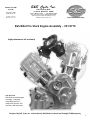
S&S Cycle, Inc.
®
Manual 51-1200
2-27-06
Copyright ®, 2006
by S&S Cycle, Inc.
All rights reserved.
Printed in the U.S.A.
235 Causeway Blvd.
La Crosse, Wisconsin 54603
Phone: 608-627-1497 • Fax: 608-627-1488
Technical Service Phone: 608-627-TECH (8324)
Technical Service Email: [email protected]
Website: www.sscycle.com
Because every industry has a leader
S&S Billet Pro Stock Engine Assembly – #31-9710
High-performance off road only!
S&S #31-9710
S&S Billet Pro Stock Engine
Assembly – Complete,
assembled, and race
ready with ignition, fuel
injection, and accessories.
Designed by S&S Cycle, Inc. and exclusively distributed and serviced through G2 Motorsports..
1
DISCLAIMER:
IMPORTANT NOTICE:
S&S parts are designed for high performance, off road, racing
applications and are intended for the very experienced rider only. The
installation of S&S parts may void or adversely effect your factory
warranty. In addition such installation and use may violate certain
federal, state, and local laws, rules and ordinances as well as other laws
when used on motor vehicles used on public highways, especially in
states where pollution laws may apply. Always check federal, state, and
local laws before modifying your motorcycle. It is the sole and exclusive
responsibility of the user to determine the suitability of the product for
his or her use, and the user shall assume all legal, personal injury risk and
liability and all other obligations, duties, and risks associated therewith.
Statements in this instruction sheet preceded by the following words
are of special significance.
®
The words Harley®, Harley-Davidson®, H-D®, Sportster®, Evolution®, and
all H-D part numbers and model designations are used in reference only.
S&S Cycle is not associated with Harley-Davidson, Inc.
SAFE INSTALLATION AND OPERATION RULES:
Before installing your new S&S part it is your responsibility to read and
follow the installation and maintenance procedures in these
instructions and follow the basic rules below for your personal safety.
● Gasoline is extremely flammable and explosive under certain
conditions and toxic when breathed. Do not smoke. Perform
installation in a well ventilated area away from open flames or sparks.
● If motorcycle has been running, wait until engine and exhaust pipes
have cooled down to avoid getting burned before performing any
installation steps.
● Before performing any installation steps disconnect battery to
eliminate potential sparks and inadvertent engagement of starter while
working on electrical components.
● Read instructions thoroughly and carefully so all procedures are
completely understood before performing any installation steps.
Contact S&S with any questions you may have if any steps are unclear
or any abnormalities occur during installation or operation of
motorcycle with a S&S part on it.
WARNING
Means there is the possibility of injury to yourself or others.
CAUTION
Means there is the possibility of damage to the part or motorcycle.
NOTE
Other information of particular importance has been placed in italic type.
S&S recommends you take special notice of these items.
WARRANTY:
All S&S parts are guaranteed to the original purchaser to be free of
manufacturing defects in materials and workmanship for a period of
twelve (12) months from the date of purchase. Merchandise that fails
to conform to these conditions will be repaired or replaced at S&S’s
option if the parts are returned to us by the purchaser within the 12
month warranty period or within 10 days thereafter.
In the event warranty service is required, the original purchaser must
call or write S&S immediately with the problem. Some problems can be
rectified by a telephone call and need no further course of action.
A part that is suspect of being defective must not be replaced by a
Dealer without prior authorization from S&S. If it is deemed necessary
for S&S to make an evaluation to determine whether the part was
defective, a return authorization number must be obtained from S&S.
The parts must be packaged properly so as to not cause further damage
and be returned prepaid to S&S with a copy of the original invoice of
purchase and a detailed letter outlining the nature of the problem, how
the part was used and the circumstances at the time of failure. If after
an evaluation has been made by S&S and the part was found to be
defective, repair, replacement or refund will be granted.
● Consult an appropriate service manual for your motorcycle for correct
disassembly and reassembly procedures for any parts that need to be
removed to facilitate installation.
ADDITIONAL WARRANTY PROVISIONS:
● Use good judgement when performing installation and operating
motorcycle. Good judgement begins with a clear head. Don't let
alcohol, drugs or fatigue impair your judgement. Start installation
when you are fresh.
(2) S&S shall have no obligation if an S&S part becomes defective in
whole or in part as a result of improper installation, improper
maintenance, improper use, abnormal operation, or any other misuse
or mistreatment of the S&S part.
● Be sure all federal, state and local laws are obeyed with the
installation.
● For optimum performance and safety and to minimize potential
damage to carb or other components, use all mounting hardware that
is provided and follow all installation instructions.
(3) S&S shall not be liable for any consequential or incidental damages
resulting from the failure of an S&S part, the breach of any warranties,
the failure to deliver, delay in delivery, delivery in non-conforming
condition, or for any other breach of contract or duty between S&S and
a customer.
● Motorcycle exhaust fumes are toxic and poisonous and must not
be breathed. Run motorcycle in a well ventilated area where fumes
can dissipate.
(4) S&S parts are designed exclusively for use in Harley-Davidson® and
other American v-twin motorcycles. S&S shall have no warranty or
liability obligation if an S&S part is used in any other application.
(1) S&S shall have no obligation in the event an S&S part is modified by
any other person or organization.
Because every industry has a leader
Designed by S&S Cycle, Inc. and exclusively distributed and serviced through G2 Motorsports..
2
S&S® has teamed up with G2 Motorsports to offer a complete engine package for use in NHRA Pro Stock Motorcycle and AHDRA Pro
Gas classes.
G2 Motorsports, Inc. was formed by George Bryce of Star Racing and S&S’s own George B. Smith to combine their talents and work
with S&S Cycle. The team worked with S&S to develop, test, and make available, high performance engine packages that are
competitive at the highest levels and readily attainable for our most discerning and demanding customers!
S&S BILLET PRO STOCK ENGINE 31-9710
SPECIFICATIONS AND OTHER INFORMATION
The S&S Billet Pro Stock is the same engine you’ve seen used in
competition at NHRA and AHDRA races. It is a 160-cubic inch
four cam, 60 degree V-Twin pushrod engine. It is built with
special S&S billet crankcases, cylinders, and heads, and
features an integral 6-speed automatic transmission. Dual
downdraft manifolds and large diameter throttle bodies for
S&S Variable Fuel Injection (VFI) and MSD MC-4 Systems are
standard on this engine.
GENERAL SPECIFICATIONS
●
●
●
●
●
●
●
●
160ci four-cam, 60 degree pushrod V-Twin
Billet crankcases with integral transmission housing
Billet steel Pro Stock style flywheel assembly
Billet aluminum rods with 1.500” crankpin
Billet Pro Stock cylinder heads
Pro Stock VFI manifolds, throttle bodies & S&S ProTune Fuel
Injection
Six-speed automatic transmission
Includes ignition system, oil pump, pulleys, VFI System, clutch
assembly, and final drive sprocket
Crank Position Sensor Gap ...............................................0.0300
Intake Rocker Arm Ratio ........................................................2:1
Exhaust Rocker Arm Ratio .................................................1.85:1
Primary Drive Ratio, 64-87 ...............................................1.359:1
Transmission High (6th) Gear Output Ratio....................1.053:1
Drive Sprocket 16 Teeth 6-30 Chain x 43T Wheel..........2.688:1
15 Teeth 6-30 Chain x 43T Wheel ............................2.867:1
Overall Drive Ratio, 41T– 46T, 43 Average .....................3.847:1
Normal Piston Size.............................................5.1100” - 5.115”
Piston Fitment....................................................0.0065” - .0072”
Top Ring Gap .....................................................................0.023”
2nd Ring Gap .......................................................................0.063”
Oil Ring Gap.......................................................................0.070”
Valve Stem to Rocker Arm Clearance (Cold) ...................0.004”
(Hot) ............................................................................0.015"
Valve Stem to Guide Clearance ......................0.00175” - .0020”
ACCOMPLISHMENTS
Cam End Play .........................................................0.010” - .020”
2004
● Won NHRA's "Best Engineered Vehicle Award"
● Qualified #1 and set a track record at Indianapolis Raceway
Park with a 7.115 ET
● Won at Las Vegas “The Strip” with a 7.191 ET 179.92 mph
● Qualified #1 and also set a track record at Pomona Raceway
with a 7.024 ET
Anticipated Valve lift; Intake............................................1.000”
Exhaust ........................................................................0.925"
2005
● Chip Ellis won Chicago and Vegas (again) and finished 5th in
national points.
● Ryan Schnitz won Denver, Columbus and the finals in
Pomona and finished 4th in national points.
● Matt Smith, riding original G2 S&S Pro Stock powered bike
"Rattletrap," posted the 3rd quickest pass in NHRA history at
7.000 ET and 189 MPH.
● Every race had S&S Pro Stock teams in the 16 bike field on
Sunday.
RIDERS/TEAMS USING THE S&S BILLET PRO STOCK ENGINE
Marco Andreano - Vroom Racing
Tom Bradford - Hal's H-D V-Twin
Connie Cohn - CC Rider Racing
Chip Ellis - G2 Motorsports
Dave Feazell - Two Wheel Travel
Matt Guidera - Rocklin Motorsports
Ronald Mac Phee - Hog Farm Racing
Chris Rivas - Mohegan Sun Racing
Ryan Schnitz - Team Muzzy
Matt Smith - G2 Motorsports
Tom Sorensen - MCPARTS - Denmark
Brett Stevens - Brett Stevens Racing - Australia
TORQUE SPECIFICATIONS:
Head Bolt 1⁄2" .....................................................................60 ft-lb
Head Bolt 3⁄8" .....................................................................35 ft-lb
See Diagram 1.
CYLINDER HEAD – TOP VIEW
TORQUE SEQUENCE DIAGRAM
All nuts to 30 ft-lb 1⁄2" first –
then 3⁄8" – next all 1⁄2" to 60 ft-lb –
then all 3⁄8" to 35 ft-lb.
Cam Side
Diagram 1
Rocker Arm Stand Bolts ...................................................60 ft-lb
Use 272 red Loctite—requires TP55 Torx Plus wrench
Rocker Arm Screws ...........................................................28 ft-lb
Use 272 red Loctite—requires TP45 Torx Plus wrench
Timing Cover Screws......................................................120 in-lb
Use 242 blue Loctite.
Bolts 5⁄16" ............................................................................18 ft-lb
Screws 1⁄4"........................................................................156 in-lb
3
Pinion Gear Nut ................................................................90 ft-lb
Use 609 green Loctite liberally on gear and nut--especially on
nut face.
Cam Gear Nut ...................................................................90 ft-lb
Use 609 green Loctite liberally on gear and nut threads
and face.
Transmission Trap Door and Case Bolts...........................18 ft-lb
Use 272 red Loctite
4.
Adjust the ignition pickup plate until it reads 38 degrees
BTDC for the front cylinder.
Repeat the process for the rear cylinder – rotating the rear
pickup for the rear cylinder instead of rotating the ignition
pickup plate as in the front cylinder. (See Diagram 2)
Loosen screws and rotate
backplate to set front cylinder.
Left Side Main Bearing Nut - coat threads lightly with nonsetting thread sealer such as Loctite 592 and torque with S&S
Wrench (PN 53-0211) to 125 ft-lbs.
EXHAUST PIPES
Front & Rear Cylinders
Section 1, 2-3/8” O/D X 7-1/2” long
Section 2, 2-1/2” O/D X 1-1/4” long
Section 3, 2-3/4” OD X 4-3/4” long
Section 4, 3” O/D X 12” long
Loosen screws and rotate
pickup to set rear cylinder.
Diagram 2
LUBRICATION
●
●
●
●
●
Engine Oil - 0 or 5wt, 1-1/2 quarts
Transmission and Primary Lube - 75w90, 2 ounces in primary,
fill transmission fluid level to overflow hole, 12 to 14 ounces
There is a .030 restrictor installed in the oil line that feeds the
bottom end – check it often to ensure that it is free of debris
There is a .015 restrictor in the left main bearing oil feed line
– check it often to ensure it is free of debris
Oil lines must be made from -4 AN braided hose
5.
6.
S&S VFI FUEL INJECTION
Please use -6 high pressure hose to plumb the VFI system.
7.
Anyone purchasing and using the S&S Billet Pro Stock Engine is
expected to attend S&S Fuel Injection School to learn the procedures
for operation and tuning the S&S VFI Pro Tune II module. G2 will
supply the latest version of the most successful map as a starting
point for proper initial operation.
IGNITION SYSTEM
Ignition Timing - Set dynamic timing at 30 degrees BTDCDO NOT use more than 31.5 degrees at any time.
Due to the large displacement and high compression of this
engine, it is important to make sure the front piston is just
past TDC on the compression stroke before starting. This gives
the starter a chance to get the crankshaft turning before it has
to push the engine through a compression stroke.
1.
2.
3.
1.
4.
2.
3.
4
STARTING PROCEDURE
Timing Instructions - The following are instructions how to
statically and dynamically time your engine using the MSD
Programmable MC-4 Ignition Control. First, familiarize yourself
with the MSD instruction sheet provided with the MC-4 ignition
control. The following summarizes how to static time the front
and rear cylinders.
Load the appropriate MSD MC-4 file for the configuration of
your motor/motorcycle. This should be coordinated with G2
Motorsports.
Disconnect all wires leading to the coils to prevent accidental
misfire. Also, disconnect the clutch switch at this time.
With the MC-4 box plugged in, roll the engine over while
simultaneously watching the crankshaft degree marks
through the primary and the red LED on the end of the
MC-4. When the red LED is illuminated, record the
crankshaft degrees BTDC.
Verify the "Run Timing Curve". Under the "View" Menu
select "Plot #1" to display the Run Timing Curve. The
MC-4 ignition box automatically subtracts 4 degrees from the
static timing number. In addition, from the "Run Timing
Curve Screen", specify the degrees of advance to subtract
from the static timing number.
For example, if the timing curve is a straight line from 1,000
RPM to 10,000 RPM at 4 degrees, the final dynamic ignition
advance will be 38 degrees minus 4 degrees (which is
automatically subtracted), minus 4 degrees from the "Run
Timing Curve Screen". The final dynamic timing is 30
degrees BTDC.
Validate the dynamic timing with a timing light at 4000 rpm.
Loosen screws and rotate backplate to set front cylinder.
Loosen screws and rotate pickup to set rear cylinder.
5.
6.
Make sure the ignition switch is turned off.
Remove the timing plate in the primary cover.
Use a 3⁄4" RATCHET handle and a short extension if needed,
insert extension into the engine sprocket and turn the
engine counter clockwise (forward) until it rolls over TDC.
The compression will make it snap over TDC with some force.
Check in the timing window to be sure the front cylinder is
at TDC. You may have to turn the engine clockwise
(backward) slightly to see the timing mark.
If the front TDC timing mark (TF) is visible, the engine is ready
to start. If the rear TDC mark (TR) appears in the window,
repeat the above procedure.
Mark the oil pump pulley for future reference. This
eliminates the need to remove the timing window.
MAINTENANCE TIPS
Crankshaft
VISUAL INSPECTION AFTER EACH RUN
●
●
●
●
●
●
●
●
●
●
●
●
●
●
Moly valve coating for cracking or flaking
Bottom spring collar for cracks.
Valve tips, lash caps
Pushrod ends and rocker cups
Top collar and keepers for excessive wear
Check valve spring pressure - replace or shim if below 380 lbs.
NOTE: Must maintain .060 minimum before coil bind at
maximum lift. Recommend replacement of questionable
springs rather than shim.
Drain and inspect oil and if necessary, pull pan and check for
debris. If OK, oil may be re-used.
VISUAL INSPECTION AS NECESSARY DURING EVENT
Cylinders/Pistons
●
●
●
●
Check wristpin for straightness and coating integrity
Visually inspect for cracks or signs of scuffing
Verify ring land straightness
Check piston domes for signs of detonation
Crankshaft
●
●
●
●
Check rod side clearance against build sheet
Visually inspect crankpin weld
Visually inspect pinion shaft weld
Check drive hub and pinion shaft runout – max is .007”
Cam Chest
●
●
●
Inspect cam gears and keys
Inspect cam shafts for excess wear and cracked welds
Inspect tappets and tappet blocks for wear or bad bearings
Check rod side clearance against build sheet
Visually inspect crankpin weld
Visually inspect pinion shaft weld
Drive hub and pinion shaft runout not to exceed .007
Replace main bearing on crankshaft every 20 runs
Replace the pinion bearing every 40 runs
Replace crankshaft at 50 runs or sooner if necessary
Cam Chest
●
●
●
●
●
●
●
Tappet blocks and lifters, service limit is .0040 maximum
Inspect cam gears and keys
Inspect cam shafts for excess wear and cracked welds
Inspect tappets and tappet blocks for wear or bad bearings
Replace cams at 50 runs or sooner if necessary
Replace lifter at 50 runs or sooner if necessary
Replace pushrods at 50 runs or sooner if necessary
Transmission
●
●
●
●
●
Replace transmission bearings as necessary or after failure of
any transmission component
Replace shift forks after backing out of any gear except sixth
or if routine inspection shows sign of wear
Replace shift drum after backing out of any gear except sixth
or if routine inspection shows sign of wear
Replace detent arm spring as necessary
Replace shift pawl as necessary
Oil Pump
●
●
Replace pump if gears/rotors are scored or as necessary
Replace pump belt if edges fray or contaminated by oil, etc.
REBUILD/REPLACEMENT SPECIFICATIONS
Heads
●
●
●
●
●
●
●
●
●
Run out of valve, service limit is .005 T.I.R.
Run out of seat, service limit is .005 T.I.R.
Valve stem wear, service limit is .310 intake, .3105 exhaust
Measure spring clearance to coil bind, service limit .060 or greater
Measure spring installed pressure, service minimum is 380 lbs
Set valve lash cold at .004, lash hot at approx. .015"
Replace valves at 50 runs or sooner if necessary
Replace valve springs at 15 runs or sooner if necessary
Replace rocker arms at 50 runs or sooner if necessary
Cylinders/Pistons
●
●
●
●
●
●
●
●
Measure piston/cylinders for fitment, service limit is .0095
Measure piston ring land lateral clearance, service limit is
.001 1st, .002 2nd
New ring installation gaps .023, .063, .070
Measure cylinders, service limit is 5.125”
Hone cylinder as necessary without exceeding service limit
for fitment
Replace piston if collapsed, service limit is .002 smaller than
specification on original build sheet
Check wristpin/piston fitment, service limit is .002
Replace pistons at 50 runs or sooner if necessary
5
REPLACING THE DRIVE SIDE CRANK MAIN BEARING
7.
It is recommended that the left (drive side) main bearing be
replaced during normal engine teardown maintenance. In the
event that you find signs of premature bearing failure and do not
have time to tear the engine down, the following procedure has
been used for bearing changes in the field. NOTE: This will only
work if the bearing is intact.
1.
2.
3.
Install plastic spacer (PN 53-0450) between the flywheel and
cam side case. NOTE: This is important to keep the flywheel
assembly from moving over into the intermediate plate
bearing and cam cover seal. See Picture 4 and 5.
Remove primary cover and oil pan.
Remove the three screws holding the starter drive in place.
Use puller to remove drive gear and starter hub. See Picture 1.
Picture 4
8.
Picture 5
Install puller (PN 53-0210) into bearing as shown in photo.
Make sure puller arms have the correct spacer to allow the
arms to lock into the race. See Picture 6.
Picture 1
4.
Insert lock ring wrench (PN 53-0211) into the lock ring and
install the 5/16-24 x 4-1/2” long bolt to securely hold wrench
to lock ring. See Picture 2.
Picture 6
9.
Picture 2
5.
6.
Begin pulling bearing. Make sure plastic spacer stays in place
during the pulling operation.
10. Once bearing is removed, clean and inspect bore making
sure threads are clean and oil supply hole is open.
11. Verify the .100 thick spacer is on flywheel.
12. Put new bearing on flywheel and install as far as you can by
hand. Make sure cage is facing in proper direction and apply
a light oil or press lube on the bearing outer and inner races
before installation. See Picture 7.
With long 3/4“ drive breaker bar loosen lock ring (counter
clockwise). Move lock ring only enough to loosen and allow
removal of 4-1/2” bolt and lock ring.
Remove gear to bearing spacer. See Picture 3.
Picture 7
6
Picture 3
13. Use the old bearing as a spacer and drive gear as a push tool
and put in the 3 screws that hold the starter drive on and
begin pulling the bearing in, turning each screw 1/4 turn at
a time. NOTE: The primary drive gear will only go on the
dowel pins one way. If the screws run out of thread switch
to the shorter 5/16-24 screws supplied with the puller and
proceed until you feel the bearing seat against the flywheel.
See Picture 8.
16. Install bearing to gear spacer ring, using a good oil or press
lube on the ring's outer and inner races.
17. Put a light coat of oil on the seal lip and add thread sealer on
the threads, such as Loctite 592. Be careful not to get any on
the face that contacts the bearing and be sure not to plug
the oil feed hole.
18. Thread the lock ring in by hand using caution not to cross
thread it. Once the ring contacts the bearing, use the lock
ring wrench and a ratchet to tighten the ring until the
bearing is fully seated.
19. Use the 5/16-24 x 4-1/2 bolt to hold the wrench tight to the
ring and torque the ring to 125 ft-lbs.
20. Install the drive gear and starter drive hub and torque the
screws to 18 ft-lbs.
For more information and a full line of parts and support
items, contact G2 Motorsports:
Picture 8
14. Remove the three screws, gear and old bearing.
15. Inspect seal in lock ring (replace if necessary) and install seal
lip out.
Derek Churchwell
G2 Motorsports, Inc.
726 Crisp Drive P.O. BOX 1241
Americus, GA 31709
229-924-0031 Fax: 229-928-2321
[email protected]
Designed by S&S® Cycle, Inc. and exclusively distributed and serviced through G2 Motorsports..
7
S&S BILLET PRO STOCK ENGINE ASSEMBLY – 31-9710
External Starter for S&S Billet Pro Stock Engine
Bulitpruf by FAE –
LOWER END PARTS
Available exclusively through
G2 Motorsports.
PRO STOCK CRANKCASE ASSEMBLY
1.
Crankcase assembly with cam chest.....................31-1025
2.
Mainshaft bearing rebuild kit ..............................31-4100
G2 Part Number is
BFMC-1 Twin Magnum Starter.
*(Includes PN 31-4090 and PN 33-4089)
3.
Unit is light weight
with heavy duty power –
two 4 1⁄2 hp motors, 24 volts.
Cylinder studs (8 pack) ...........................................31-2390
4.
Main bearing, drive side .....................................31-4090*
5.
Flywheel assembly .................................................32-3008
6.
Flywheel to main bearing spacer .........................50-0367
3
5
6
2
2
1
4
9
8
S&S BILLET PRO STOCK ENGINE ASSEMBLY – 31-9710
LOWER END PARTS
PRO STOCK OIL PICK-UP PLATE
7.
Oil pick-up plate with hardware ..........................56-5052
8.
Oil adapter fitting with hardware .......................56-5053
9.
O-ring string 25 ft .................................................50-0402
7
8
BILLET PRO STOCK ENGINE ASSEMBLY – 31-9710
LOWER END PARTS
PRO STOCK CAM CHEST
8.
Upper pushrod tube o-ring
(10 pack)
.....................93-4046
Intermediate plate assembly ................................31-6526
9.
Lower pushrod tube o-ring
(10 pack)
.....................93-4047
Cam pinion/drive gear kit .....................................33-4280
10. Tappet block set (Front & Rear) ..............................33-5400
4.
Cam chest cover assembly.....................................31-6525
11. Tappet set ..............................................................90-4131
5.
Cam chest rebuild kit ............................................33-1050
12. Cam chest .....................................................................N/A
6.
Pushrod set (2 Intake – 2 Exhaust) ...........................93-5125
13. O-ring string 25 ft .................................................50-0402
7.
Pushrod tube cover set (4 Pieces)...........................93-4045
14. Pinion shaft bearing............................................33-4089*
1.
Cam set (must be degreed and welded) .............33-5196
2.
3.
6
7
8
2
9
5
10
12
11
5
5
13
4
14
3
5
1
5
13
5
9
S&S BILLET PRO STOCK ENGINE ASSEMBLY – 31-9710
LOWER END PARTS
PRO STOCK PRIMARY COVER
1.
Clutch cover with hardware .................................56-5050
8.
Primary drive gear, 64 teeth, with hardware........56-5041
2.
Clutch hub cover spacer kit ..................................56-3039
9.
Reluctor wheel with dowel pins ..........................33-2064
3.
Primary cover with hardware ...............................56-5051
10. O-ring string 25 ft .................................................50-0402
4.
Clutch cable tab with hardware...........................56-3024
11. 20 tooth oil pump drive pulley ............................31-3901
5.
Timing hole cover with hardware........................31-4099
12. 2 3⁄8” external retaining rings ................................50-8341
6.
Outboard bearing support assembly ...................31-3906
13. Outboard support bearing ...................................31-0421
7.
Drive hub with hardware .....................................33-2060
14. Clutch assembly, 87 teeth .....................................56-3022
14
9
2
10
3
10
8
4
5
13
6
1
12
7
11
10
S&S BILLET PRO STOCK ENGINE ASSEMBLY – 31-9710
11. Exhaust flanges with gaskets and hardware
CYLINDER HEADS AND PARTS
Front and rear .....................................................16-0251
PRO STOCK HEAD ASSEMBLY
12. Exhaust flange gasket packet, (2 pack) ..............16-0253
1.
13. Pushrod cover with hardware
Head Assembly
Front head assembly ............................................90-1465F
Front .....................................................................93-4098
Rear head assembly .............................................90-1465R
Rear.......................................................................93-4099
2.
Rocker cover with hardware ...............................90-4133
3.
Rocker arm set
Cylinder set – front and rear without pistons ..91-4032
Front and rear intake and exhaust.....................90-4166
Cylinder set – front and rear with pistons .........91-4033
Intake rocker arms with hardware
Front cylinder only...............................................91-4032F
Front and rear ......................................................90-4164
Rear cylinder only ................................................91-4032R
4.
5.
14. Cylinders
Exhaust rocker arms with hardware
15. O-ring, head and base.........................................50-7955
Front and rear ......................................................90-4165
16. Hardware, cylinder stud, billet PS ......................50-4000
Rocker arm support set with hardware
17. Keepers, (8 pack) .........................................................90-2160
Front and rear ......................................................90-4162
18. Valve springs, (4 pack)................................................90-2291
7.
Valve spring kit – front and rear .......................90-2290
19. Button-head cap screw, (5 pack) .............................50-0322
8.
Seat and guide set – front and rear ...................90-2180
20. Lash caps (2 pack) ........................................................90-2166
9.
Intake valve ..........................................................90-2131
21. Titanium top collars, (4 pack) ...............................90-2134
6.
10. Exhaust valve........................................................90-2132
Not Shown:
22. Replacement ductile iron cylinder liner .............93-4810
23. O-ring string 25 ft................................................50-0402
17 21
2
18
1
8
7
5
16
11
19
4
12
3
8
10
15
6
8 20
15
9
14
13
11
S&S BILLET PRO STOCK ENGINE ASSEMBLY – 31-9710
PISTON PARTS
1.
Piston set,
Standard-Includes wristpins and rings ................92-4925
Oversize (.005”) ....................................................92-4926
2
2.
Piston ringset – For two pistons ..........................94-4400X
3.
Wristpin clips – (8 Pack) .........................................94-9276
4.
Wristpin – Each .....................................................94-9281
1
3
4
1
2
S&S BILLET PRO STOCK ENGINE ASSEMBLY – 31-9710
6
INTAKE MANIFOLDS AND PARTS
1.
Radiused inlet and hardware
Front .......................................................................11-2158
3
Rear ........................................................................11-2159
2.
Throttle body assembly
Front .......................................................................16-5097
Rear ........................................................................16-5098
3.
Intake manifold with hardware
Front .......................................................................16-3574
5
Rear ........................................................................16-3575
4.
Injector hat ............................................................55-5053
5.
Fuel injector ...........................................................55-5051
6.
Throttle position sensor – Rear manifold only....55-5036
4
12
S&S BILLET PRO STOCK ENGINE ASSEMBLY – 31-9710
20. Fuel pump ..............................................................50-5042
MISCELLANEOUS PARTS
21. Fuel pressure regulator .........................................55-5045
1.
S&S VFI module with ProTune II CD .....................55-5006
22. 22.5" Oil pump timing belt ..................................31-3921
2.
Wiring harness, 1995 1⁄2 - 2001
23. 18 Tooth oil pump driven pulley
Magneti module....................................................55-1091
with set screw ........................................................31-3900
3.
MSD trigger and backplate ..................................55-1206
24. Oil pre-filter, with hardware (2 pack) ......................90-2253
4.
Rotor, retaining washer and screw ......................55-1207
26. 90° fitting...............................................................50-0326
5.
MSD coils................................................................55-1575
27. 45° fitting...............................................................50-0394
6.
MSD spark plug wires, 8.5mm (Set of 4) ..............55-1203
7.
Map sensor.............................................................55-1037
8.
Air temperature sensor .........................................55-5041
9.
Crank position sensor............................................31-2090
TOOLS
28. Bearing puller assembly ........................................53-0210
29. Threaded lock ring removal tool .........................53-0211
30. Bearing removal tool spacer.................................53-0450
10. 10 ohm resistors ....................................................55-1566
ADDITIONAL PARTS (NOT SHOWN)
11. Head temperature sensor .....................................55-1014
● Plug, SH pipe, 1⁄8 -27 npt (10 pack) .......................50-1015
12. Champion spark plugs (Set of 4)............................55-1202
● SHCS, 1⁄4 -20 x 3⁄4" sems (10 pack)............................50-1032
13. MSD MC-4 ignition box.........................................55-1205
● O-ring string (25') .................................................50-0402
14. Drive sprocket,
● Kit, Seal, Billet Pro Stock Engine ..........................31-7500
16 teeth 6-30 chain ...............................................33-4168
● Kit, Seal, PS Transmission ......................................56-5200
15 teeth 6-30 chain ...............................................33-4169
2
15. 1⁄8" Drive sprocket spacers .....................................56-5046
16. ⁄4" Drive sprocket spacer.......................................56-5047
1
17. 20mm nut for drive sprocket................................50-0297
1
18. Dailey oil pump. ....................................................31-6226
19. Oil pump trash screen ...........................................31-3922
4
3
13
5
12
6
15
14
9
16
17
8
7
11
10
28
20
26
25
21
24
29
18
30
19
22
23
13
S&S BILLET PRO STOCK ENGINE ASSEMBLY – 31-9710
TRANSMISSION PARTS
6.
Transmission sensor bracket with screws.............56-3005
7.
Gear shift cam stopper with hardware................56-5062
8.
Left shifting cover with hardware .......................31-0402
1.
Drive side trap door assembly ..............................56-3010
9.
Right shifting cover with hardware .....................56-5063
2.
Right side trap door assembly ..............................31-0405
10. 1⁄4 x 1⁄2 90 degree vent fitting .................................50-0326
3.
Transmission hardware kit ....................................56-5059
11. 1⁄4 -28 SHCS ..............................................................50-0341
4.
Gear shift shaft with hardware ............................56-1114
12. Transmission speed sensor magnets.....................50-5067
5.
Shifting-drum and guide-pawl stopper plates
13. Transmission speed sensor rotor ..........................56-3036
with screws ............................................................56-5061
14. Retaining ring........................................................56-1116
15. Second gear input, 15 teeth .................................56-1113
Not Shown
56
Transmission assembly, with left trap door ................56-1100
1
25
55
24
54
23
1
40
37
39
18
14
19
38
53
37
22
36
30
32
1
35
1
29
34
52
8
3
29
48
49
50
63
1
2 51
49
50
47
6
4
3
10
7
5
9
2
4
14
S&S BILLET PRO STOCK ENGINE ASSEMBLY – 31-9710
37. Thrust washer ........................................................50-7146
Continued...
38. Bearing, plain (for #1 output gear) .......................56-1098
16. Splined bushing .....................................................56-1036
39. First gear output, 31 teeth, 2.8185 ratio .............56-1103
17. Sixth gear input, 19 teeth.....................................56-1112
40. Ring, external retaining, constant cross-section
18. Splined input thrust washer .................................50-7147
.082"diameter x .050"...........................................56-1097
19. Spring coil ..............................................................50-8407
41. Spring long ............................................................50-5066
20. Fourth gear input, 18 teeth..................................56-1111
42. Spring medium ......................................................50-5064
21. Gear spacer ............................................................56-1117
43. Spring short ...........................................................50-5063
22. Third gear input, 18 teeth ....................................56-1110
44. Output forks ..........................................................31-6107
23. Bushing, fifth gear input ......................................56-1099
45. Shift fork shaft out................................................56-1023
24. Fifth gear input, 22 teeth .....................................56-1109
46. 7⁄16 Snap ring external fork shafts..........................50-8210
25. Input shaft .............................................................56-1021
47. Pole gear shift no. 1 ..............................................31-6071
26. Spacer, right side output shaft .............................56-3023
48. Pole gear shift no. 2 ............................................31-6072
27. Output shaft ..........................................................56-1022
49. Shifting pawl roller ...............................................31-6106
28. Second gear output, 29 teeth, 1.933 ratio ..........56-1108
50. Spring, shift pawl ................................................11-2147
29. Washer, splined output thrust .............................56-1093
51. Gear shift cam .......................................................31-6070
30. Ring, external retaining,
52. Shift drum ..............................................................56-1020
1.077"diameter x .050" thick ...............................56-1096
53. 25mm external retaining ring ..............................50-8209
31. Sixth gear output, 20 teeth, 1.053 ratio ..............56-1107
54. Output shaft retaining washer.............................50-7006
32. Bearing, splined-plain (for #4 gear) .....................56-1095
55. 1⁄4 -28 1" FHCS output shaft ...................................50-0324
33. Fourth gear output, 23 teeth, 1.278 ratio ...........56-1106
56. Spacer clutch, trans input, pro stock B60 ............56-3006
34. Ring, external retaining,
57. Input forks .............................................................31-6108
1.093"diameter x .075" thick ...............................56-1094
58. 1⁄2" External snap ring ............................................50-8212
35. Third gear output, 27 teeth, 1.500 ratio .............56-1105
59. 1⁄2" x .040 thick washer ..........................................50-7144
36. Fifth gear output, 25 teeth, 1.136 ratio ..............56-1104
60. Detent arm.............................................................11-2128
61. Detent arm spring .................................................11-2157
14
21
62. Shift fork shaft input ............................................56-1024
14
63. 10mm external retaining ring ..............................50-5061
20
19
14
18
17
16
33
32
46
15
60
58
14
30
62
12
31
61
30
29
59
11
28
57
2
22
27
46
13
12
45
2
44
42
26
43
41
15
Because every industry has a leader
16