1
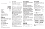
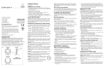
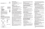
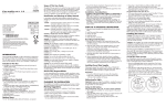
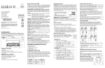
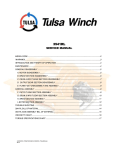
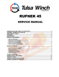
iW Blast TR
Industry-standard theatrical and rental LED wash fixture with intelligent
white light
iW Blast TR
Industry-standard theatrical and rental LED wash fixture
with intelligent white light
iW Blast TR is a rugged, intelligent white LED fixture designed specifically to withstand taxing stage, set, and
touring environments. This rental-friendly fixture offers ease of installation and control, along with the ability
to produce high-quality white light with a temperature range of 2700 K to 6500 K. It features a standard
4-pin XLR connector, an innovative elastomeric sleeve that protects the fixture during rough handling, and a
pivoting bezel for easy exchange of lenses. An industrial-grade hinge affords quick and reliable fixture aiming
and locking. The mounting base easily accommodates truss clamps and other mounting and positioning
options. Designed with live entertainment in mind, iW Blast TR is the ideal intelligent white LED fixture for
demanding temporary and touring environments.
• Wide range of color temperature and brightness
— Channels of warm white and cool white LEDs produce color temperatures ranging
from 2700 K to 6500 K. You can adjust fixture
brightness while varying or maintaining constant
color temperature.
• Quick fixture aiming and locking — An industrialgrade constant torque hinge offers stable, 110°
fixture tilting for quick and dependable aiming.
Standard set screws lock the fixture in position
without special tools.
• Versatile mounting options — The pre-assembled
mounting base offers a range of options for
mounting on the floor or various stage truss
clamps. An integral safety bracket lets you easily
attach a safety tether.
• On-board temperature monitoring — A
compensation circuit prevents damage to the
fixture if operating temperatures rise to unsafe
levels. An auto-cycling feature automatically
restores normal operation after 30 minutes.
FPO
2
iW Blast TR Product Guide
Photography: Tom Boner
• Pivoting bezel and exchangeable lenses — The
pivoting bezel and included 23° soft-focus and 10°
clear tempered glass spread lenses let you switch
quickly between soft-edge wash lighting and
extended beam projection.
Rustic Kitchen Bistro & Bar, in Wilkes-Barre, PA, shown
above and on the cover, films weekly cooking shows from
its in-house restaurant studio. Twelve iW Blast TR fixtures,
suspended above the kitchen on a semicircular truss,
illuminate the on-air host and guests with a precise shade of
uniform white light. During filming, the color temperature
can be adjusted on the fly to white-balance the highdefinition cameras, rendering colors on-screen exactly as
they appear in person. iW Blast TR lets studio chefs and
patrons throughout the restaurant take advantage of highquality white light without the heat and power consumption
of conventional light sources.
• Industry-standard power and control — iW Blast
TR works seamlessly with the full range of Philips
DMX controllers, such as iPlayer 3, ColorDial Pro, or any third-party DMX controller. City
Theatrical Inc. offers a complete line of power /
data supplies specifically designed for use with iW
Blast TR fixtures.
Innovative Protective Sleeve
Because stage and set environments can take
their toll on equipment, iW Blast TR features
an innovative elastomeric sleeve to protect
the fixture and lens from the rigors of multiple
setups and teardowns.
Photometrics
Photometric data is based on test results from an independent NIST traceable testing
lab. IES data is available at www.philipscolorkinetics.com/support/ies.
iW Blast TR
23º frosted lens
Lumens
Efficacy
1469
29.4 lm / W
Polar Candela Distribution
0
90º
Cd: 0
1,006
80º
2,012
70º
3,108
60º
4,023
5,029
50º
6,035
VA: 0º
10º
20º
- 0º H
30º
0
5
15
25
35
45
55
65
75
85
90
Candela Table
22.5 44 67.5
Illuminance at Distance
Center Beam FC
90
6003 6003 6003 6003
5236 5278 5235 5189
1872 1873 1879 1845
542 542 543
532
201 201 199
196
94
95
95
94
54
54
55
56
30
30
31
33
10
10
12
14
0
0
1
1
0
0
0
0
6003
5108
1799
520
191
92
55
32
14
1
0
4.3 ft
Beam Width
320 fc
1.6 ft
1.6 ft
80 fc
3.3 ft
3.3 ft
36 fc
4.9 ft
4.9 ft
20 fc
6.5 ft
6.5 ft
13 fc
8.2 ft
8.2 ft
9 fc
9.8 ft
9.8 ft
8.7 ft
13 ft
17.3 ft
21.7 ft
26 ft
77.5 ft (23.6 m)
1 fc maximum distance
40º
- 90º H
Vert. Spread: 21.3º
Horiz. Spread: 21.4º
Coefficients Of Utilization - Zonal Cavity Method
Zonal Lumen
Zonal Lumen Summary
Zone Lumens % Lamp % Luminaire
0-30
1,177.1 80.1%
80.1%
0-40
1,302.0 88.6%
88.6%
0-60
1,423.5 96.9%
96.9%
60-90
45.3
3.1%
3.1%
0-90
1,468.8 100%
100%
90-180
0
0%
0%
0-180 1,468.8 100%
100%
Total Efficiency: 100%
RCC %:
RW %:
RCR: 0
1
2
3
4
5
6
7
8
9
10
70
1.19
1.14
1.09
1.04
1.00
.96
.93
.89
.86
.83
.81
80
50 30
1.19 1.19
1.11 1.09
1.04 1.01
.99 .94
.93 .88
.89 .84
.85 .80
.81 .76
.78 .73
.75 .70
.73 .68
0
1.19
1.07
.98
.90
.85
.80
.76
.73
.70
.67
.65
70
1.16
1.11
1.07
1.02
.98
.95
.91
.88
.85
.82
.80
70
50 30
1.16 1.16
1.09 1.07
1.03 .99
.97 .93
.92 .88
.88 .83
.84 .79
.81 .76
.78 .73
.75 .70
.72 .68
Effective Floor Cavity Reflectance: 20%
50
30
10
0
50 30 20
50 30 20
50 30 20
0
0
1.00 1.11 1.11 1.11 1.06 1.06 1.06 1.02 1.02 1.02 1.00
.95 1.05 1.04 1.02 1.01 1.00 .99 .98 .97 .96 .94
.90 1.00 .97 .94 .97 .94 .92 .94 .92 .91 .89
.85 .95 .91 .88 .92 .89 .87 .90 .88 .86 .84
.81 .90 .86 .83 .88 .85 .82 .86 .84 .81 .80
.77 .86 .82 .79 .85 .81 .78 .83 .80 .78 .76
.74 .83 .78 .75 .81 .78 .75 .80 .77 .74 .73
.71 .79 .75 .72 .78 .75 .72 .77 .74 .71 .70
.68 .77 .72 .69 .76 .72 .69 .75 .71 .69 .67
.66 .74 .70 .67 .73 .69 .66 .72 .69 .66 .65
.64 .71 .67 .64 .71 .67 .64 .70 .67 .64 .63
RCC %: Ceiling reflectance percentage, RW %: Wall reflectance percentage, RCR: Room cavity ratio
iW Blast TR
10º clear lens
Polar Candela Distribution
90º
Cd: 0
6,864
Lumens
Efficacy
1679
33.6 lm / W
80º
13,728
70º
20,593
60º
27,457
34,321
50º
41,185
VA: 0º
10º
20º
- 0º H
30º
0
Candela Table
22.5 44 67.5
Illuminance at Distance
Center Beam FC
90
0 40724 40724 40724 40724 40724
5 18090 1846118629 18569 17567
15
573 743 813 810
746
25
203 207 207
205
205
35
35
44
47
47
42
35
32
27
25
25
45
35
37
30
42
42
55
25
7
2
5
5
65
0
0
0
0
0
75
0
0
0
0
0
85
0
0
0
0
0
90
8.7 ft
13 ft
17.3 ft
Zonal Lumen Summary
Zone Lumens % Lamp % Luminaire
0-30
1,590.5 94.7%
94.7%
0-40
1,623.5 96.7%
96.7%
0-60
1,674.1 99.7%
99.7%
60-90
5.2
0.3%
0.3%
0-90
1,679.3 100%
100%
90-180
0
0%
0%
0-180 1,679.3 100%
100%
Total Efficiency: 100%
.7 ft
1.3 ft
1.4 ft
241 fc
2.0 ft
2.1 ft
136 fc
2.7 ft
2.8 ft
87 fc
3.4 ft
3.5 ft
60 fc
4.0 ft
4.2 ft
26 ft
40º
Zonal Lumen
.7 ft
542 fc
21.7 ft
- 90º H
Beam Width
2,169 fc
4.3 ft
202 ft (61.6 m)
1 fc maximum distance
Vert. Spread: 8.8º
Horiz. Spread: 9.1º
Coefficients Of Utilization - Zonal Cavity Method
Effective Floor Cavity Reflectance: 20%
RCC %:
RW %:
RCR: 0
1
2
3
4
5
6
7
8
9
10
70
1.19
1.16
1.13
1.10
1.08
1.06
1.04
1.02
1.00
.99
.97
80
50 30
1.19 1.19
1.14 1.12
1.10 1.07
1.06 1.03
1.03 1.00
1.01 .98
.99 .95
.97 .94
.95 .92
.94 .91
.93 .90
0
1.19
1.11
1.05
1.01
.98
.95
.93
.91
.90
.89
.88
70
1.16
1.13
1.11
1.08
1.06
1.04
1.03
1.01
.99
.98
.97
70
50 30
1.16 1.16
1.12 1.10
1.08 1.06
1.05 1.02
1.02 .99
1.00 .97
.98 .95
.96 .93
.95 .92
.93 .91
.92 .89
0
1.00
.98
.97
.95
.94
.92
.91
.90
.89
.88
.87
50
1.11
1.08
1.05
1.03
1.00
.99
.97
.95
.94
.93
.92
50
30
1.11
1.07
1.03
1.00
.98
.96
.94
.93
.91
.90
.89
20
1.11
1.06
1.02
.99
.96
.94
.92
.91
.90
.88
.87
50
1.06
1.04
1.02
1.00
.99
.97
.96
.94
.93
.92
.91
30
30
1.06
1.03
1.01
.99
.97
.95
.93
.92
.91
.90
.89
10
0
50 30 20
0
20
1.06 1.02 1.02 1.02 1.00
1.03 1.01 1.00 1.00 .98
1.00 1.00 .99 .98 .96
.97 .98 .97 .96 .95
.95 .97 .95 .94 .93
.93 .96 .94 .93 .92
.92 .95 .93 .91 .90
.90 .94 .92 .90 .89
.89 .92 .90 .89 .88
.88 .91 .89 .88 .87
.87 .91 .88 .87 .86
RCC %: Ceiling reflectance percentage, RW %: Wall reflectance percentage, RCR: Room cavity ratio
For lux multiply fc by 10.7
iW Blast TR Product Guide 3
Specifications
Due to continuous improvements and innovations, specifications may change without notice.
Item
Output
Electrical
Control
Physical
Certification
and Safety
Specification
Details
Beam Angle
23° / 10°
Lumens*
1469 (23° beam angle) 1679 (10° beam angle)
Color Temperature†
2700 K – 6500 K
Efficacy (lm / W)
29.4 (23° beam angle) 33.6 (10° beam angle)
Mixing Distance
6 in (152 mm) to uniform light
CRI
83 all, 83 warm, 74 cool
Lumen Maintenance‡
70,000 hours L70 @ 25° C (typical application)
Input Voltage
24 VDC via PDS-750 TRX, PDS-375 TRX, PDS-150e, or PDS-60
Power Consumption
50 W maximum at full output, steady state
Interface
DMX via power / data supply
Control System
Philips full range of controllers, including Light System Manager,
iPlayer 3, or any third-party DMX controllers
Dimensions
(Height x Width x Depth)
8 x 13.5 x 2.6 in (203 x 343 x 66 mm)
Weight
6.4 lb (2.9 kg)
Housing
Die-cast aluminium, black powder-coated finish
Lens
Frosted glass (23º beam angle) Clear glass (10° beam angle)
Fixture Connections
6 ft (1.8 m) power / data cable with 4-pin XLR connector
Temperature Ranges
-40° – 122° F (-40° – 50° C) Operating
-4° – 122° F (-20° – 50° C) Startup
-40° – 176° F (-40° – 80° C) Storage
Humidity
0 – 95%, non-condensing
Maximum Cable Length
Up to 54 ft (16.5 m) extension for total of 60 ft (18.3 m)
maximum
Certification
UL / cUL, FCC Class B, CE, CCC, C-Tick
Environment
Dry Location, IP20
110º
110º
10º Beam Angle
23º Beam Angle
110º Rotation
In addition to the PDS-750 TRX power / data supply, City Theatrical Inc. offers a line of power / data supplies
specifically designed for Blast TR fixtures. Visit www.citytheatrical.com for details.
City Theatrical Inc. offers a line of polycarbonate
holographic lenses for iW Blast TR, with a range of
symmetric and asymmetric beam angles. Visit www.citytheatrical.com for details.
* Lumen measurement complies with IES LM-79-08 testing
procedures.
† Color temperatures conform to nominal CCTs as defined in
ANSI Chromaticity Standard C78.377A.
‡ L70 = 70% lumen maintenance (when light output drops below 70% of initial output). Ambient luminaire temperatures specified. Lumen maintenance calculations are based on lifetime
prediction graphs supplied by LED source manufacturers. Calculations for white-light LED fixtures
are based on measurements that comply with IES LM-80-08 testing procedures. Refer to www.
philipscolorkinetics.com/support/appnotes/lm-80-08.pdf for more information.
13.5 in
(343 mm)
6.0 in
(152 mm)
2.6 in
(66 mm)
6.75 in
(171 mm)
Ø 0.5 in
(13 mm)
Ø 0.2 in
(5 mm), 4x
Ø 3.5 in
(89 mm)
4
iW Blast TR Product Guide
8.0 in
(203 mm)
2.0 in
(51 mm)
4.0 in
(102 mm)
Fixtures and Data / Power Supplies
iW Blast TR fixtures are part of a complete low-voltage system which includes one or
more power / data supplies and any third-party DMX controller.
Replacement parts
Included in the box
Item
Item Number
Philips 12NC
iW Blast TR
501-000001-00
910503700183
Protective Sleeve
120-000062-00
910503700370
Mounting Base
120-000060-00
910503700369
Lenses (23° frosted glass and 10° clear glass)
120-000066-00
910503700367
PDS-375 TRX
109-000030-01
910503702284
PDS-750 TRX
109-000030-00
910503702319
iW Blast TR fixture with 6 ft (1.8 m) leader cable
Frosted glass 23° lens
Clear glass 10° lens
Protective elastomeric sleeve
3/16 in hex key wrench
Installation Instructions
E You must remove the fixture’s protective
sleeve before you can attach the accessory
holder. Reinstall the protective sleeve after
use.
Accessories
Designed specifically for the family of Blast fixtures, accessories provide additional
options for controlling and dispersing light. Accessory holders screw to the side of
the fixture and are required for mounting accessories. Accessory holders prevent
accessories from falling out if the fixture is tipped or hung upside down.
Item
Type
Item Number
Philips 12NC
Accessory Holders
Black
120-000003-04
910503702840
Half Top Hats
Black
120-000009-04
910503702848
Top Hats
Black
120-000005-04
910503702844
Egg Crate Louvers
Black
120-000015-04
910503702852
Barndoors
Black
120-000019-04
910503702856
Horizontal Glass Spread
Lens*
36° (ribs out) / 50° (ribs in)
120-000025-00
910503703897
Horizontal / Vertical Glass
Spread Lens*
40°
120-000025-01
910503703898
* Intended for use with Blast fixtures with 10° clear lens
Use Item Number when ordering in North America.
iW Blast TR Product Guide 5
Installation
iW Blast TR fixtures are designed for easy setup, configuration, and teardown You
can connect iW Blast TR fixtures directly to a power / data supply, such as the PDS750 TRX, using the built-in 6 ft (1.8 m) power cable with standard XLR connector.
Owner / User Responsibilities
It is the responsibility of the contractor, installer, purchaser, owner, and user to
install, maintain, and operate iW Blast TR fixtures in such a manner as to comply
with all applicable codes, state and local laws, ordinances, and regulations. Consult
with the appropriate electrical inspector to ensure compliance.
E Refer to the iW Blast TR Installation
Instructions for specific warning and
caution statements.
Create a Lighting Design Plan
1. Determine the appropriate location of each power / data supply in relation to the
light fixtures, and of the light fixtures in relation to each other.
iW Blast TR connects to the power / data supply over a built-in 6 ft (1.8 m)
leader cable with a standard 4-pin XLR male connector. The leader cable can be
extended with a standard XLR male to XLR female patch cable, up to a maximum
overall length of 60 ft (18 m).
The number of iW Blast TR fixtures that each power / data supply can support is
determined by such factors as the supply’s capacity and number of available ports,
line voltage, circuit load, voltage drop, and leader cable lengths. The PDS-750
TRX, for example, can support up to 12 iW Blast TR fixtures, each with a leader
cable of up to 60 ft (18 m).
2. On an architectural diagram or other diagram that shows the physical layout of
the installation, identify the locations of all switches, controllers, power / data
supplied, fixtures, and cables.
Start the Installation
1. Install all power / data supplies, including any interfaces with controllers. Power
/ data supplies and external controllers send power and control signals to the
fixtures over the fixture’s leader cable.
2. Verify that all additional supporting equipment (switches, controllers) is in place.
3. Ensure that all additional parts and tools are available, including:
• The included 3/16 in hex key wrench for locking the fixtures in position
• A Phillips head screwdriver for removing the bezel screws
• C-clamps or bases for pipe, truss, or floor mounting, as required
Install the Fixtures
Make sure the power is OFF before mounting and connecting iW Blast TR fixtures.
1. The mounting base of each iW Blast TR fixture provides a clearance hole for a
1/2 in bolt for mounting to a pipe, truss, weighted base, or floor using a standard
theatrical C-clamp or other mounting hardware. When mounting iW Blast TR,
ensure that the installation is suitable and safe and that the hardware is properly
rated for the task.
6
iW Blast TR Product Guide
Leader Cable connector dimensions
0.75”
19 mm
0.03”
0.82 mm
2.75”
70 mm
Leader cable pinouts
Pin
Signal
Wire Color
1
+24 VDC
Red
2
(not used)
3
Data
White
4
DC Common
Black
1
2 3
4
2. When mounting iW Blast TR fixtures on the floor or a base, ensure that the
fixture sits flush to the surface and use mounting hardware suitable for the
mounting surface.
E For complete instructions on how to wire
the PDS-750 TRX, refer to the PDS-750 TRX
User’s Manual.
3. Connect each iW Blast TR fixture to an available female 4-pin output on the
power / data supply, iW Blast TR fixtures are provided with a permanently
connected 6 ft (1.8 m) cable. The leader cable can be extended with a standard
XLR male to XLR female patch cable, up to a maximum overall length of 60 ft (18 m).
Exchanging iW Blast TR Lenses
E To ease removal and replacement of
the protective cover, run the fixture at
full power until the heat from the fixture
housing softens the cover material.
iW Blast TR is designed to let you quickly and easily exchange lenses. The clear 10º
lens is designed for long throw and spotlighting applications, while the frosted 23º
lens is designed for wash lighting applications. The 23º lens is factory installed, and
the 10º lens is included in the box.
1. Remove the protective cover from the fixture.
2. Using a Phillips head screwdriver, remove the two lock-down screws located on
each side of the fixture at the top of the bezel. (Do not remove the pivot screws
on the edge of the bezel closest to the base.)
3. Using the tabs on the bezel, pivot the bezel forward to access the lens.
4. Remove the installed lens.
5. Clean both sides of the lens using a mild, non-abrasive cleaner. Handle the lens by
the gasket, making sure not to touch or soil either surface. Place the lens in the
fixture housing, making sure the gasket around the lens is properly fitted. Install
the frosted 23° glass lens smooth side up.
6. Close the bezel, tighten the lock-down screws, and replace the protective cover.
iW Blast TR Product Guide 7
Attach Safety Cable
(Optional)
Safety cable bracket location on fixture
Each iW Blast TR fixture is designed for use with a safety cable to tether it to a
secure anchor point. When dictated by local or state code or advised by a structural
engineer, attach a safety cable to the bracket on the back of the fixture using a
standard carabiner clip. Attach the safety cable to the mounting surface using a
method that follows the code or engineer’s requirements.
Address and Configuring
For installations in which you want to change the brightness and color temperature
of all fixtures in unison, no fixture addressing or configuration is necessary.
To support dynamic effects that automatically modify brightness and color
temperature on individual fixtures, you must address and configure iW Blast TR
Powercore fixtures as you would any color-changing (RGB) fixture.
iW Blast TR Powercore fixtures use DMX addresses to communicate with
controllers. The number of DMX addresses each iW Blast TR Powercore fixture
requires depends on the fixture’s configuration.
Safety cable minimum requirements
Material
316 Stainless Steel
iW Blast TR Powercore fixtures operate in 8-bit mode by default. You can configure
fixtures to operate in 16-bit mode, which increases resolution for smoother dimming
and more precise control. In 8-bit mode, fixtures use one DMX address per LED
channel. In 16-bit mode, fixtures use two DMX addresses per LED channel. The first
DMX address corresponds to the “coarse” data for that channel, and the second
corresponds to the “fine” data. By using double the number of DMX addresses,
16-bit mode increases fixture resolution from 256 dimming steps to 65,536 (256 x
256) dimming steps.
Size
5/64 to 3/16 in (2 to 5 mm) nominal
diameter. Minimum break load must be
greater than 400 lbs (181 kg)
Construction
7 x 7 (49 wires) preformed stranded
You can address and configure iW Blast TR Powercore fixtures in much the same
way as you would address any RGB fixture. The red channel corresponds to the
warm LEDs, the green channel corresponds to the cool LEDs, and the blue channel
is not used. Note that although the blue DMX channel is not used, it is assigned, so
that each iW Blast TR Powercore fixture uses three sequential DMX addresses (or a
multiple of three addresses).
iW Blast TR Powercore fixtures come factory-addressed with a starting DMX
address of 1. For lighting designs where fixtures work in unison, all fixtures can
be assigned the same starting DMX address. Changes to the default starting DMX
addresses are not necessary, but if lights were previously readdressed for use in
other installations, you must reset them. For light show designs that show different
light output on different fixtures simultaneously, you must assign unique DMX
addresses to your fixtures and sort them in a useful order.
The following table shows the DMX channel assignments for 8-bit and 16-bit iW
Blast TR Powercore configurations, assuming a starting DMX address of 1.
DMX Channel Assignments
8-bit Mode
16-Bit Mode
8
1
2
3
Warm
Cool
Unused
1
2
3
4
5
6
Warm
Warm
Cool
Cool
Unused
Unused
iW Blast TR Product Guide
E If necessary, you can individually
address iW Blast TR fixtures using
QuickPlay Pro and SmartJack Pro. You can
download QuickPlay Pro and the Addressing
and Configuration Guide from www.
philipscolorkinetics.com/support/addressing/
LED Channels
RGB
iW Blast TR Powercore
Red
Warm
Green
Cool
Blue
Unused
Aim and Lock the Fixtures
Make sure the power is ON before aiming and locking iW Blast TR fixtures.
E Do not look directly into the fixture
when aiming and locking.
Using the provided hex key wrench, loosen the tilting set screws located on the front
of the fixture’s mounting base. Aim the fixture by tilting the beam as desired. Tighten
the set screws to lock the fixture in place.
FRONT VIEW
Aim fixture and
lock in place.
iW Blast TR Product Guide 9
10
iW Blast TR Product Guide
iW Blast TR Product Guide 11
Philips Color Kinetics
3 Burlington Woods Drive
Burlington, Massachusetts 01803 USA
Tel 888.385.5742
Tel 617.423.9999
Fax 617.423.9998
www.philipscolorkinetics.com
Copyright © 2010 – 2012 Philips Solid-State Lighting Solutions, Inc. All rights reserved.
Chromacore, Chromasic, CK, the CK logo, Color Kinetics, the Color Kinetics logo, ColorBlast,
ColorBlaze, ColorBurst, eW Fuse, ColorGraze, ColorPlay, ColorReach, iW Reach, eW Reach,
DIMand, EssentialWhite, eW, iColor, iColor Cove, IntelliWhite, iW, iPlayer, Optibin, and Powercore
are either registered trademarks or trademarks of Philips Solid-State Lighting Solutions, Inc. in
the United States and / or other countries. All other brand or product names are trademarks
or registered trademarks of their respective owners. Due to continuous improvements and
innovations, specifications may change without notice.
Cover Photo: Tom Bomer: Rustic Kitchen, Mohegan Sun
at Pocono Downs, Wilkes-Barre, Pennsylvania
DAS-000012-00 R03 05-12