1
Installation and Operation Manual
X-VA-MT3750C-eng
Part Number: 541B063AAG
April, 2014
Section 2 Installation
Brooks® Ar-MiteTM MT3750C
both high alarm and low alarm applications. A circuit is completed by
connecting wires to “Alarm In” and to either “HI” for high flow alarm or
“LO” for low flow alarm. Wires used should be in the range from 12 to
20 AWG. Remove 0.3 inches of insulation before inserting the wire into
the terminal block and tightening the screw.
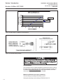
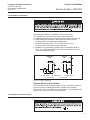
For electrical hook-up of units requiring intrinsically safe power connections, use Brooks optional power supply and relay connected as in
Figure 2-6 for the integral alarm.
2-10 Installation of Transmitter
A. For intrinsically safe operation (recognized by a BLUE COVER),
intrinsic safety barrier selection, cable parameters and power supply
limits must be in accordance with the entity parameters shown in Figure
2-6. Do not connect the zero wire (keep it floating) when the transmitter
is in normal operation. The zero wire is not meant to be extended as
zeroing must be done locally.
B. If the area classification is Division 2 and Zone 2, a barrier is not
required and cable parameters are not applicable. The electrical code
will require the use of conduit for wire protection. Refer to Figure 2-7.
C. If the installation is to be protected by Division 1 and Zone 1 explosionproof methods, explosion-proof installation methods must be followed.
Refer to Figure 2-8.
D. The power supply voltage determines the maximum resistance of the
loop, the associated cable and the barrier. Always be sure that the
voltage on the transmitter is within the specifications.
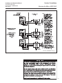
E. After installation and powering of the loop, the transmitter must be
zeroed to compensate for any stray magnetic effects in the vicinity of
the transmitter. The zero function may be activated as part of a periodical maintenance check. The zero function is activated by momentary
(>2 seconds) shorting the zero wire to the ground wire while power is
on. Connect the transmitter as shown in Figure 2-9.
2-5