1
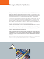
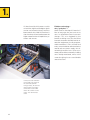
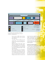
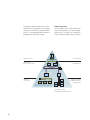
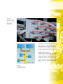
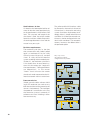
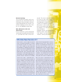
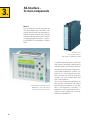
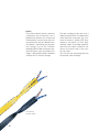
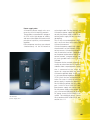
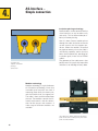
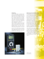
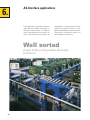
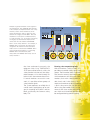
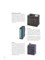
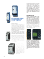
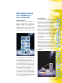
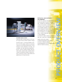
All about AS-Interface
An overview for new
and experienced users
as-interface
Basics
Design
Practice
Utility
Get a Great Connection
The “eyes and ears“ of production
When you automate a process, sensors and actuators are always required. Whether it be in a logistics center, where light barriers check the position of a package on a conveyor belt, in a beverage bottling plant where the liquid level is checked, or in a steel mill where beams have to be
cut at a precise position. Sensors – the eyes and ears of process control – are everywhere.
For a long time, these transmitters and transducers were cabled in the same old way: Each individual sensor and actuator was directly wired to the higher-level control, resulting in complex
and messy bundles of cables with the associated electrical cabinets. In the mid nineties, with
the introduction of the AS-Interface®, bus technology – already a standard at the field and control level – established itself in the world of binary sensors and actuators.
A general standard was agreed on which was rugged and flexible enough to fulfill all of the requirements of an industrial data bus. However, it simultaneously addressed the special requirements of the “lowest” control level. Now, process-related devices (sensors, actuators, and operator units) can be interlinked with one another and connected to industrial communication
systems – and that extremely simply and effectively.
In all of the automation technology, the AS-Interface is the simplest and most favorably priced
solution. As of now, there is no serious competition. With the backing of a strong international
organization as well as the leading manufacturers, AS-Interface will dominate the market, also
in the future.
This brochure addresses those interested in the AS-Interface as well as users and provides an insight into the technology behind the AS-Interface and how it is used in the field.
Contents
1.
2.
3.
4.
AS-Interface –
Just another bus system?
Field bus technology –
why “go by bus”?
Industrial communication
Supervisory level
Field or process control level
Actuator/sensor level
5.
4
5
6
7
7
AS-Interface – The perfect solution
AS International Association
8
Requirements of AS-Interface
8
Single master system
9
Small volumes of data
10
Real-time requirements
10
Data transmission
10
Network topology
11
More AS-Interface
with new Specification
11
AS-Interface –
Its main components
Master
Slave
Links
Cables
Power supply units
Additional components
for expansion with …
… repeaters
… extenders
12
13
13
14
15
AS-Interface in practice
Beginner’s checklist
Configuring
Addressing of the individual nodes
Parameterisation
Operation
Ten valuable tips on assembly
What to do if something
goes wrong
19
21
21
22
22
23
25
6.
AS-Interface applications
Empty bottle sorting
at Bier Schneider
26
Material handling with AS-Interface
at the VW engine plant
28
AS-Interface in operation
with laser cutting machines
30
7.
AS-Interface and safety
Safety at work
How does it all work
and can it really be safe?
Forming safe component groups
8.
AS-Interface and Siemens
Approval
Service and support
Product overview
32
32
33
34
34
35
16
17
AS-Interface – Simple connection
Modular technology
18
Insulation piercing technology
18
3
1.
AS-Interface with which process and local machine, digital and analogue signals
can be transmitted in binary form has
been around since 1994. AS-Interface is
also the universal interface between the
higher control level and simple binary actuators and sensors.
In the past each individual
sensor had to be wired to
the controller (parallel
wiring). Today, the sensors
and actuators are simply
connected to each other
and to the control via one
cable – the AS-Interface
cable.
4
Field bus technology –
why “go by bus”?
What made us develop AS-Interface?
Not so long ago, the pressure to cut
costs in automation forced structural
changes. This was triggered by the
immense cabling costs that had to be
invested to connect the field level to automation equipment (usually programmable controllers). Every actuator and
every sensor had to be connected to the
control and to a power supply, that involved high material costs (wire costs
money too) and the astronomical cabling
costs already mentioned, whilst at the
same time giving rise to a considerable
source for errors.
Previous costs: 100 %
Conventional
26.6 %
AS interface
Control
I/O distribution assembly
Cables
I/O cabling
Cable assembly
I/O cabling assembly
I/O distribution material
Sensors
due to savings in
configuration,
commissioning, and
flexibility of system
expansion
Courtesy of:
TU München
Prof. Reinhard
Prof. Milberg
A comparison of the costs between conventional
installation technology and AS-Interface using the
example of a milling machine.
Even as late as 1997, 36% of all machine and plant failures were caused by
the installation.
The magic word was (and still is) decentralisation – first in automation technology, later in drive and switching technology, too.
What was meant by that? Well, simply
that the conventional, cost-intensive parallel wiring (cable looms) was replaced
by a serial field bus, or a two-wire cable
with which all automation nodes can be
interconnected.
The cost advantages are considerable:
For example, according to a study by
the Technical University of Munich, you
can save more than 25% of the installation costs if AS-Interface is used on a
milling machine. Even if the costs for
the AS-Interface modules are initially
higher, savings up to 15% to 30% in total are quite common. The savings are
to be seen in reduced configuration, and
commissioning time, and in achieving
greater flexibility when the system has
to be expanded.
Industrial communication
The structure of a complex automation
system is pretty opaque even for experts: Numerous control devices are
networked on different data networks
and with different protocols. It has become customary to divide control levels
according to hierarchies. They differ in
their time response, degree of protection, type and use of data to be transmitted and many other aspects.
5
To help you understand the tasks of ASInterface and its position in the control
hierarchy in industrial communication,
here is a short explanation of the basic
properties of the various levels.
Supervisory level
At the highest level, the supervisory
level, the computers on the management level in a factory, or sometimes
even in more than one factory, are inter-
Host computer
Supervisory level
Industrial
Ethernet
Programmable controllers
e.g. SIMATIC S7
Production or
process control level
PROFIBUS
Actuator/
sensor level
AS-Interface
Sensors, actuators
e.g. BERO, contactors,
coupling relays
The various levels
in industrial communication
6
networked, or a host computer controls
production as a whole using the computers as slaves. The data volume is in
the megabyte range and transmission
of the data does not need to be in real
time. The transmission medium might
be Ethernet.
Field or process control level
At the field and process level,
PROFIBUS® (process field bus) has become standard. With a transmission rate
of up to 12 Mbits/s in its DP version, it is
ideal for the high demands of automation technology. PROFIBUS is now available as PROFIBUS-PA for process control, and the extensions added in 1999
for synchronism and peer-to-peer traffic
will make it suitable for use in typical
motion control applications in the future.
Actuator/sensor level
The actuator sensor level is the lowest
level in the field area. Here, binary actuators and sensors in the field and
process area are networked. Many of
the devices connected, supply or require binary signals (e.g. BERO®; contactors, motor starter, solenoid valves,
pneumatics, valve islands etc.). The necessary data volume is small, but the
speed of data transmission is very high.
A typical application for AS-Interface.
AS-Interface has had an excellent track
record in more than two million nodes
since its introduction and has proven the
most low-cost, robust, and best suited
solution for the task, almost without
competition.
7
AS-Interface –
The perfect solution
2.
Before the task of developing a bus system, for the lowest field level which
was both open and manufacturer independent (just like Ethernet or
PROFIBUS) could be undertaken, a simple problem had to be solved: Components supplied by a wide range of different manufacturers which all had to be
connected to the same bus system
were not necessarily able to communicate smoothly with one another and
with the system.
AS International Association
In 1990, eleven renowned companies
active in the sensor and actuator field
formed a consortium to make their components compatible.
That AS-Interface project gave birth to
the AS International Association whose
main tasks lay in, international standardisation, continued development of
the system and certification of products.
The user can recognise tested and certified products by the AS-Interface
“shadow logo” and a test number.
8
Requirements of AS-Interface
At the lowest control level, sensors,
contactors, motor circuit switches, indicator lamps, pushbuttons etc. which
transfer volumes of information in the
bit range had to learn to communicate.
The bus systems already in existence
were either over dimensioned or simply
could not be used for such a task. They
used cables that were either too expensive or unsuitable for a direct link to
the process (e.g. fibre-optic cable,
shielded and non-flexible cable), and the
volumes of data transmitted were simply too high. Either the data protocols
were non- deterministic or the control
electronics used were much too expensive if each binary sensor was to be a
bus node and in an automation network
there might be any number of them.
Over and above that, assembly and installation needed to be as simple as possible, without the need for any special
training. The costs for each connection
should be low and in keeping with the
volume of data to be transferred.
In short: AS-Interface had to be able to
network binary sensors and actuators
and link them to the higher control levels, very simply, inexpensively, and
meeting industrial requirements.
With IP67,
AS-Interface is well
equipped to deal
with dust, humidity,
and extreme
temperatures.
Master
Power supply
Slave
Slave
Slave
AS-Interface cable
The technical result is remarkable. ASInterface fulfils all the requirements just
about perfectly, in field use (IP65/IP67),
in the control cabinet (IP20), and in temperature ranges from -25 °C to +85 °C.
Single master system
AS-Interface was conceived as a single
master system with cyclic polling. This
means that there is only one control
module (master) in the AS-Interface network which polls the data of the other
nodes (slaves) at precisely defined intervals.
Minimum
configuration of an
AS-Interface network
9
Small volumes of data
AS-Interface has been optimised for volumes of data that correspond precisely
to the requirements of the lowest field
level. The structure and length of the
data frame is fixed. Up to four useable
Input bits and four useable Output bits
are exchanged between a slave and the
master in any one cycle.
Real-time requirements
The maximum cycle time, i.e. the time
that a master takes until a node is polled
again is a maximum of 5 ms for a fully
utilised system with up to 31 standard
slaves. In a fully utilised AS-Interface
system according to the extended specification 2.1, the maximum cycle time is
10 ms for 62 slaves. In most control systems this time meets the “tough realtime requirements”. Polling procedures
are deterministic, i.e. the master
“knows” that it can access the current
data of each node connected to the ASInterface network within a certain time.
Data transmission
Simple two-wire cables without shielding or PE conductor are used to carry
both data and the auxiliary power for the
sensors simultaneously. The intelligent
data protocol is structured in such a way
that the entire system is extremely interference resistant. Shielding is therefore not necessary.
10
The yellow profiled AS-Interface cable
has become a characteristic feature of
AS-Interface. Its innovative contacting
system (insulation displacement technology) makes it simple and efficient to
assemble. An AS-Interface network can,
of course, also be configured with standard circular conductors. For economic
reasons, however, the ribbon cable is
the preferred option.
Bus, star, or tree
AS-Interface network
configurations are possible
Bus
Master
Star
Master
Tree
Master
Network topology
The AS-Interface network can be configured like any conventional electrical
installation. Due to the robust functioning principle behind the structure, any
network topology can be used. Tree,
bus, or star topologies are possible.
More AS-Interface with new
Specification
In an AS-Interface system configured
and designed according to Specification
2.1, up to 62 A/B slaves can be con-
nected. The slaves have the capability
of having 4 input and 3 output addresses maximum (i.e. up to 248 inputs
and 186 outputs within an AS-Interface
system). In a standard AS-Interface system up to 31 slaves can be connected,
each slave having up to 4 inputs and up
to 4 outputs (i.e. a total of 124 inputs
and 124 outputs).
Intelligent sensors with integrated ASInterface chips each have their own
slave address and are interpreted as
“normal” slaves by the master.
AS-Interface Version 2.1
With Version 2.1 you can operate up to 62
slaves instead of the previous 31 on one
AS-Interface network. This works as follows: The 31 addresses that are possible
and available in a standard AS-Interface network are split into two independent subaddresses - e.g. in 1A and 1B. If you use this
option for all 31 slaves, a total of 62 stations
are possible. To take advantage of this new
specification a new range of compatible ASInterface masters and slaves are available.
The new V2.1 slaves – called A/B slaves –
have up to four input and three output addresses available. On the front of the new
modules, increased “easy-to-use” diagnostics are possible by means of LED’s.
Other added benefits of the new specification are that improved transmission times
are now capable for analogue input or output slaves. An AS-Interface network can
now consist of old and new slaves (i.e.
Standard and version 2.1 AS-Interface) allowing upward and downward integration
of existing AS-Interface networks. This
means that existing applications can be expanded with new V2.1 slaves and V2.1
masters can communicate with the existing slaves on a network. It must be remembered that masters that do not support
Specification 2.1, can only support standard
slaves and not the new A and B slave addresses. The actual principle of operation is
as follows: The standard slaves are polled
in each cycle (max. cycle time: 5 ms). Even
if only one A or B slave is installed at an address, this slave is scanned in each cycle
with a maximum cycle time of 5 ms. If only
one A/B slave pair is installed at an address,
the A slave is scanned in one cycle, and the
B slave is scanned in the next (max. cycle
time: 10 ms). A/B slaves can be addressed
like standard slaves via all new commercially available AS-Interface addressing units
that conform with the new Specification
2.1.It should be noted that any AS-Interface
addressing units that do not conform with
the new Specification 2.1 can only re-address A/B slaves as an A slave.
11
3.
AS-Interface –
Its main components
Master
The AS-Interface master provides the
link to the higher-level controller. It organises data transmission along the ASInterface cable automatically, making
the signals of the sensors and actuators
available to higher-level bus systems,
e.g. PROFIBUS, at an interface. See also
Links.
Example of an
AS-Interface master:
CPU 343-2 for SIMATIC S7-300
The complete controllers of the
SIMATIC S7 range can also be
used as AS-Interface masters
12
In addition to polling signals, the master
also transfers parameter settings to the
individual nodes, continuously monitors
the network and performs diagnostics.
Unlike more complex bus systems, ASInterface is a self-configuring system.
The user does not have to make any
settings, e.g. access authorisation, data
rates, frame type etc.
The master automatically performs all
the functions required for the correct
functioning of AS-Interface. It also performs self-diagnostics functions. It
recognises faults and automatically assigns the correct address to a slave removed for maintenance.
Up to four binary
sensors and
actuators can be
connected to a
standard ASInterface module.
Decentralised startup of a DC motor:
No problem with
the DC starter
module and
AS-Interface
Slave
The most important component of the
whole AS-Interface system is so small
that would fit comfortably on a fingernail.
But without it, AS-Interface would never
have become as important as it is today.
We’re talking about the AS-Interface slave
chip. Slaves are actually distributed I/O
modules of the programmable controller
(PLC).
AS-Interface modules recognise the data
bits transmitted by the master and returns their own data. Up to 4 binary sensors and actuators can be connected to
any one standard AS-Interface module.
An intelligent slave is one where the ASInterface chip is integrated into the sensor or actuator. Costs for electronics are
minimal.
AS-Interface slaves are available as digital, analogue, and pneumatic modules,
and as intelligent nodes, e.g. motor
starters, LED columns or membrane keyboards. Single-acting and double-acting
pneumatic cylinders can be controlled
with pneumatic modules. That means not
only savings in cabling, but in tubing, too!
Links
In more complex automation structures,
AS-Interface can also be connected to a
higher level field bus, e.g. PROFIBUS. For
this, it requires a gateway (e.g. DP/AS-i
link) which is used as an AS-Interface
master in the AS-Interface network but
which functions as a slave in the higher
level field bus (e.g. PROFIBUS). In such a
configuration, AS-Interface is the supplier
of binary signals to any higher level field
bus system.
13
Cables
The yellow profiled cable has become
synonymous with AS-Interface. It has a
geometrically defined cross-section and
simultaneously transmits data and auxiliary power to the sensors. Additional auxiliary power is required for the actuators
(aux. voltage, e.g. 24 V DC). Different
coloured profiled cables have been specified utilising the same installation technology. A black profiled cable is therefore
used for 24 V DC auxiliary voltages.
AS-Interface
profiled cables
14
The core insulation usually consists of a
rubber mixture (EPDM). For applications
where demands are greater, e.g. resistance to chemicals, profiled TPE (thermoplastic elastomer) or PUR (polyurethane) cables are available. However,
round two-wire cables without PE conductor can also be used as the transmission cable.
The transmission technology obviates
the need for cable shielding.
Power supply units
AS-Interface power supply units are a
necessity of an AS-Interface network.
They produce a controlled DC voltage of
30 V DC with a high degree of stability
and low residual ripple and work on the
principle of a primary switched-mode
regulator.
Data and power are always transmitted
simultaneously via the AS-Interface
AS-Interface
power supply unit
twisted-pair cable. For that reason, the
AS-Interface power supply units ensure
not only the power supply to the AS-Interface power supply unit but also data
decoupling.
That is why no standard power supply
units must ever be used to power an
AS-Interface network.
AS-Interface power supply units supply
the electronics of the network (AS-Interface master, AS-Interface modules)
and all connected sensors. Depending
on the power requirement of the AS-Interface network, a range of power supply units graded from 2.4 to 7 A are
available.
The power for the actuators (outputs) is
usually not taken from the AS-Interface
cable but from a separate power supply
that is connected to the slaves by
means of a separate cable (e.g. black
AS-Interface profiled cable). In this way,
it is also possible to implement EMERG.
STOP circuits for local and remote isolation. For cases in which an auxiliary
power supply is required in addition to
the AS-Interface power, the very compact 1 x 30 V DC and 1 x 24 V DC combined power supply unit can be used.
For the power supply to the output circuits an external additional 20 to 30 V
DC power source (AUX POWER) is required. The additional power source
must conform to VDE 0106 (PELV), protection class 111.
15
Additional components
for expansion with …
The AS-Interface functions without any
problem with standard components up
to a length of 500 m – without repeaters or extenders up to 100 m.
… repeaters
When using repeaters, up to two repeaters can be connected in series, on
which all components can be distributed to the segments in any way. But
there is a widespread misunderstand-
ing that an AS-Interface network therefore
has a maximum extent of 300 meters!
Much larger extents are possible because
parallel arrangement of several lines in a
star configuration is possible. In a mail sorting system, an AS-Interface network has a
total extent of 1600 meters. The repeater
works as an amplifier. The slaves can be
connected to all AS-Interface segments.
Each segment requires a separate power
supply unit. In addition, the repeater isolates the two segments, which improves
selectivity in the event of a short-circuit.
Repeater
Repeater
Power
supply
unit
Slave
Power
supply
unit
Slave
Master
Segment
max. 100 m
16
Segment
max. 100 m
Segment
max. 100 m
… extenders
The AS-Interface cable can also be
lengthened by 100 m using extenders,
in which case no slaves must be used
in the first segment. Extenders are only
recommended for covering large distances, say, between the control cabinet and the plant.
A total cable length of up to 500 m with standard components:
two lines with a star network topology run in opposite directions
from the centrally located master each to a repeater. The maximum
permissible cable length between the master and all repeaters is
100 m, so that if 2 extenders are used a distance of 50 m can be
covered. After each repeater, a new segment begins, each with a
cable length of 100 m. With further repeaters the network can
again be expanded by 100 m on both sides. This results in a total
length of 500 m for one AS-Interface network.
Repeater
Repeater
Power
supply
unit
Slave
Segment
max. 100 m
Power
supply
unit
Slave
Segment
max. 100 m
17
AS-Interface –
Simple connection
4.
Insulation piercing technology
Profiled cables can be connected to the
slave interfaces at any location easily
and safely. This has been made possible by insulation piercing.
How it’s done: Contact needles pierce
through the cable insulation and make
secure contact with the copper conductor. When the needles are pulled
out again to remove a slave, the cable’s
self-healing capability means that the
holes close automatically, providing full
insulation again (in the case of EPDM
cables).
The geometry of the cable means that
polarity reversal is practically impossible
and there is no shielding to worry about.
It couldn’t be
simpler: Insulation
piercing
connection
Modular technology
Modular technology is a typical element
of AS-Interface technology. Slaves that
are made up of two parts are used: A
mounting plate forms the lower part,
and the module itself, the upper part.
The cable is then sandwiched between
the two. The modules contain the ASInterface electronics and the connections for the sensors and actuators. A
wide range of different modules are
available.
The cables are simply placed on the lower
plate of the slave. In this picture, the lower
plate of a K45 module
18
AS-Interface
in practice
5.
AS-Interface has not only become a standard industrial interface for connecting simple
binary devices. The claim of “easy entry without special bus know-how” is not exaggerated. On the contrary: The superiority of AS-Interface lies in its simplicity.
Beginner’s checklist
Here is a checklist of 10 points for the beginner, to make entry into the world
of AS-Interface even easier:
1.
How many inputs and outputs are needed?
The number of inputs and outputs tells you how many AS-Interface networks you need.
2.
How much power do the I/Os consume?
The total power requirement of the required modules determines which AS
interface power supply unit you need. As it is not possible to connect power
supply units in parallel, a power supply unit sized to the power requirement
must be used.
3.
Are special cables required?
Any combination of profiled and round cables is possible. External conditions
determine whether rubber, TPE or PUR cables have to be used. Repeaters
or extenders (See Page 16) have to be used for cable lengths above 100m.
4.
Is address assignment correct?
For clarity’s sake, a plan should be drawn up, clearly showing which
addresses are assigned to which slaves. Double assignments are not
necessarily recognised as errors by the master.
5.
Which modules belong to which addresses?
Modules and slaves that are addressed should be labelled clearly.
19
6.
When are the modules mounted?
Only when points 4 and 5 have been dealt with. Cables can be routed in any
way.
7.
How is it all configured?
The configuration is simply read in by entering the AS-Interface profile for
each slave in the master. This usually happens automatically but can be
done manually in the controller software.
8.
Are the slaves detected?
First you must check whether the master has recognised all its slaves. Only
then can you switch to protected operation and switch the controller to
RUN.
9.
How is testing done?
Input/output tests are performed by the familiar PLC method, i.e. the
sensors are activated locally and then checked in the PLC.
10. How do you get the whole thing up and running?
You can either create your own controller software in the usual way or use
existing software. In the latter case, you might have to adapt the symbolic
assignment of addresses.
20
Configuring
As far as AS-Interface is concerned, configuring means nothing more than drawing up a list of the configured slaves and
then storing it in the master. Configuring is usually performed at the master,
which means that the master automatically reads in the network configuration.
(The user can also make settings for
special applications at the PLC).
The slave address and the slave type (ID
code), the I/O configuration (I/O code),
and the parameters (in the case of intelligent sensors), if they exist, are defined during configuration. The master
uses this list to check that the configuration programmed matches the actual
configuration. Before this is possible,
the slaves must be addressed.
Addressing of the individual nodes
The addresses of all the slave nodes
must be programmed before AS-Interface is put into operation. You can do
this offline with an addressing device,
online at the master of the AS-Interface
system, or after installation using integrated addressing sockets.
The addresses themselves are the values 1 to 31 or 1 A/B to 31 A/B with the
extended specification. A new slave that
has not yet been addressed has address
0 A new slave that has not yet been addressed is assigned the address 0. It is
then recognised by the master as a new
slave that has not yet been addressed,
a state in which it is not yet involved in
normal communication procedures.
The slaves can be assigned any address
– it does not matter whether a slave assigned address 21 is followed by slave
28, or whether the first slave is assigned
address 1.
Addressing unit
for AS-Interface
21
Parameterisation
Usually, slaves are not parameterised.
Only intelligent slaves with required options are parameterised. The data sheet
of the slave in question defines whether
it has to be parameterised and what
function the parameters have. Whereas
the address of a slave never changes in
normal operation, the parameters are
very likely to change. We therefore
make the distinction between variable
and fixed parameters.
Fixed parameters are defined only once
during configuration. The parameters
themselves are bits, of which four are
made available to each module, each of
which can be set to 0 or 1. They are
transferred to the slaves when the system is started up.
22
Operation
As soon as the AS-Interface system is
set up, i.e. all the components have
been installed, the slaves are addressed
and, where necessary, parameterised,
and configuration is complete, it’s time
to start: The system switches to normal
operation, and the master runs in protected mode.
Only the slaves that have been configured are activated. Slaves that are not
configured – e.g. those that have been
added subsequently – merely return an
error signal. All you have to do to include
such a slave in the communications network is to switch to configuring mode.
The function “Configure slaves” sees to
that. It’s as easy as that.
The system is constantly monitored,
both when it is started up for the first
time and during normal operation. The
necessary data, such as voltage, mode,
incorrect configuration etc., is sent to
the higher-level controller by the AS-Interface master, e.g. in the form of a diagnosis.
Ten valuable tips on assembly
The following 10 tips should be followed to make sure nothing goes wrong during assembly:
Tip 1 – Power supply unit
On no account must AS-Interface be grounded! Never use a normal power
supply unit only AS-Interface power supply units (PELV) with integrated data
de- coupling and connect “ground (GND)” with system ground.
Tip 2 – Network extention
Without repeaters or extenders the AS-Interface cable must be no longer
than 100 m – including all feeders to the assembly terminals! If you want to
expand the network please note the following:
Expansion with extenders:
• The maximum cable length between the extender and the master must be
no longer than 100 m
• Do not connect any slaves or AS-Interface network power supply unit
between the master and the extender.
• Lines “+” and “-” must not be swapped round.
Extension with repeaters:
• Up to two repeaters must be connected in series - that makes the cable
length in a feeder no more than 300 m (i.e. 3 segments with up to 100 m).
• An AS-Interface power supply unit must be connected at every repeater.
• An extender must not be connected beyond a repeater
Tip 3 – Slaves
Each slave address must only be used once. Only use addresses 1 to 31 or
1A to 31B in A/B technology (Specification 2.1). Please note: All modules
that contain the SAP 4.1 chip can be readdressed any number of times.
Tip 4 – Additional auxillary power
If slaves are to be given an additional auxiliary power supply
• A PELV power supply unit and, if necessary, the black profiled auxiliary
power cable should be used.
23
Tip 5 – Routing of the cable
When laying the AS-Interface cable please note the following:
• Always use the yellow profiled AS-Interface cable where possible, brown
for “+” and blue for “-”.
• Even whilst communication along the AS-Interface cable offers a high
degree of EMC immunity, it should still be routed away from power cables,
even in the control cabinet!
• Every AS-Interface line requires its own cable. AS-Interface cables must
not be laid together with others in a bus cable.
• If individual cores are used (e.g. in the control cabinet), always lay parallel
core pairs. In standard stranded wires, lay individual cores together or twist
them.
Tip 6 – Ensuring EMC
Connect all inductance’s, e.g. contactor and relay coils, valves, brakes, with
suppresser diodes, varistors or RC elements. If frequency converters are
used, always use network filters, output filters, and shielded motor cables.
Tip 7 – Sensor and actuator power
Sensors and actuators must be supplied directly from the associated input
or out-put of the slave. The cables should be kept as short as possible and
away from energy cables, i.e. the slave modules should be as close as
possible to the sensors and actuators.
Tip 8 – Installation of frequency converters
• Always follow the assembly guidelines in the operating instructions.
• Connect the cable shield, e.g. between filter and frequency converter and
between the frequency converter and the motor, directly at both ends with
a large contact surface, and with a sufficient cross section (at least 4mm2).
• Connect all metal parts to system ground.
Tip 9 – System expansion 2.1
With masters to Specification 2.1 it is possible to operate A/B slaves and
analog slaves according to Definition 7.3/7.4 (only as standard slaves).
Tip 10 – Status/diagnostics
For speedy diagnostics, the status and diagnostics bits should be analysed
in the PLC.
24
What to do if something
goes wrong
Errors can occur even in the best systems. In AS-Interface too, there are error
patterns that are usually easy to detect
and just as easy to eliminate. The only
error that AS-Interface cannot recognise
is the failure of a binary sensor or actuator integrated in a module.
A defective slave can simply be replaced by a new slave. An AS-Interface
cable break will of course result in the
failure of slaves. By locating their position it is possible to find the cable break
because the slaves located beyond the
interruption point from the point of view
of the master can then no longer be addressed.
A short circuit can have a disastrous effect on the system. The master therefore recognises a short circuit by the
APF bit (AS-Interface Power Fail) and
immediately takes action. All slaves immediately go into the status “not active”. For the actuators that means that
power stops flowing.
25
6.
AS-Interface applications
Three applications have been chosen to
show you how flexible AS-Interface is:
Whether empty bottles of different
types are distributed to the correct stations, overhead conveyor motors are
controlled in a car engine plant, or a highspeed laser-cutting machine is completely networked by using AS-Interface:
Everywhere, AS-Interface shows just
how flexible and efficient it is.
Well sorted
Empty bottle sorting at Bier Schneider,
Dortmund
26
Germany’s largest
bottle sorting plant
which covers
a surface of 60 x
30m on three floors.
A total of 8 ASInterface lines all
with a maximum
cable length of
100 m provide full
I/0 cabling.
The company Dr. Wiewelhove in Telgte,
Westphalia, has designed and built what
is now the largest empty bottle sorting
plant in Germany for Bier Schneider in
Dortmund. The plant which covers a
surface of 60 x 30m over three floors
identifies and distributes up to 6,000
crates of every possible type every hour
to a maximum of 14 stations.
AS-Interface is used to link the signal I/O
of the sorting equipment to four
SIMATIC S7-300s. The CP342-2 communication processor is the master and
provides the link between the CPU of
the controller and the AS-Interface. More
than 100 digital modules each with four
digital input signals connect the sensors
distributed around the plant with the
controllers. For the most part, these are
Photo Electric Cells that ensure that
there are no jams. Two masters are
used for each controller, which means
that a total of eight AS-Interface lines
with a maximum cable length of 100 m
is sufficient for the entire I/O cabling.
20 pneumatic AS-Interface compact
modules also operate in the plant. By
reducing the entire installation to a few
cables, such as AS-Interface, compressed air and emergency stop circuits, considerable areas of the plant
could be standardised. One important
aspect for H. Pelz, head of electrical design at Dr. Wievelhofe, were the huge
savings on assembly and installation
that AS-Interface made possible: “ASInterface made it possible for us to assemble a plant at low cost on schedule,
the reduced configuring phase being an
important factor.”
27
Round she goes
Material handling with AS-Interface
at the VW engine plant in Saxony Germany
Putting the load feeders, e.g. motor
starters, into the field means transferring the advantages of field bus communication to the power side. Switching and protection devices are mounted
in close vicinity to the motor, so that the
motor cable itself is very short. The distributed motor starters draw the energy
they require from a single “power bus”.
This is the distributed motor starter concept that Volkswagen AG implemented
in their car engine factory in Chemnitz,
Saxony. A circular rotating overhead
conveyor system which transports approximately 2,200 manufactured engines daily forms the backbone of the
entire engine factory. It provides the
connection between all the production
areas, from the assembly line, through
the engine testing bays, to the dispatch
areas.
The distributed configuration of the I/O
functions, such as the connection of
the input and output signals, or the drives and their controls is made possible
28
2,200 engines are
checked, conveyed,
and stopped daily.
The stoppers are
controlled by ASInterface compact
starters.
by AS-Interface. Only a few central
control elements, e.g. for in- feed and
safety technology, now remain in the
control box.
Switches controlled by barcode readers
are responsible for the controlled passage of the engines through the individual production sections of the circular
conveying system.
Stoppers which can uncouple individual
engines from the conveyor belt are used
to ensure that a defined distance is kept
between the individual engines as they
move along.
AS-Interface compact starters control
these stoppers. Up to seven stopper
motors can be wired up to the energy
bus of a starter, making planning, assembly, and installation of the plant considerably easier. Standard I/O modules,
compact starters and the SIGNUM® operating equipment of AS-Interface also
meant that the hardware was configured in a very short time.
29
At the speed
of light
AS-Interface in operation
with laser-cutting machines
The HSL2502 high-speed laser-cutting
machine is the new showcase machine
of Trumpf based in Neukirch, Saxony,
Germany. The machine was networked
completely using AS-Interface at the
field level, including the auxiliary devices
such as the hydraulic unit, extraction,
closed-circuit cooling unit, and the infeed system.
One of the important advantages of the
new automation concept for Trumpf is
that customer specific solutions can now
simply be incorporated into existing electrical engineering projects. Thanks to
standardized I/O interfaces, it is now
possible to install and commission modules during the pre-production stage.
The distributed installation using standard modules facilitates the modular design of the machine. By using AS-Interface it is not only the PLC I/O modules
that are eliminated, but also significant
reductions can also be achieved by not
having the requirements for the sockets
in the control cabinet to connect the machine. A further benefit was also realized in that the location of the main control cabinet no longer has any effect on
the design of the machine.
Because the necessary safety functions
can be integrated into AS-Interface, a
30
Reduced stocking of
spare parts thanks to
standardized
components. It is
possible to dispense
with the typical
terminal boxes and
cable and connector
assemblies for digital
inputs and outputs
and for selected
analog signals.
special safety bus is not required. By
only having one cable for the machine
control, large wiring looms are no longer
a part of the features associated with
such high dynamic machines.
With the use of standardized components, spares stocking profile is reduced
and it is possible to dispense with the
terminal boxes, cable and connector assemblies typically used for the digital
and analog signals. That means that
there are not so many connection diagrams are previously required, a further
cost consideration in favor of using ASInterface.
Trumpf has calculated that on their machines, the higher hardware costs are
already compensated for by lower installation costs. If logistics, service, and
storage are taken into account, the company is making still further savings with
AS-Interface.
31
7.
AS-Interface
and safety
No risks must be taken when it
comes to the safety relevant components of manufacturing automation e.g. emergency stop switches,
light barriers, protective door contacts, safety light grids etc. Uninterrupted functional reliability of
all the sensors and actuators
with reliable feedback signals in
the millisecond range have top priority
when it comes to protecting personnel
and equipment from injury and damage.
For many years, these demands meant
considerable additional investments in
automation systems, because the conventional solution for failsafe actuators
and sensors has always been parallel circuitry.
Safety at work
With the components “Safety at work”,
AS-Interface fulfils the requirements for
32
a safety bus. Safety related and non
safety related digital I/O data can be
transmitted along the same AS-Interface
cable.
How does it all work and can it
really be safe?
Included in the list of AS-Interface components already familiar to us (master,
slave, power supply unit …) is the safety
monitor and safety related slaves that
are operated on the same AS-Interface
network.
The master identifies the safety related
slaves in the same way as any other
slave and integrates it in the network
like all conventional slaves.
The transmission protocol and the cable
of the standard AS-Interface are so robust that they can also be used for
safety related telegrams. The required
safety is achieved by additional signal
transmission between the safe slaves
and the safety monitor. The safety monitor waits for a four bit telegram from
each safety related slave which continuously changes according to a defined
algorithm. If the telegram expected from
a safety related slave does not arrive or
Example of group formation of safe signals in
the AS-Interface: The 3 EMERG. OFF buttons
in the example are implemented in such a way
that they can be connected directly to the
yellow AS-Interface cable. In that way, they
conform to category 4 to EN 954-1. The safe
module has 2 safe inputs. Standard sensors,
e.g. limit switches, etc. to category 2 (2 inputs)
or category 4 (1 dual-channel input) can be
connected. The safe module and EMERG:
OFF 1 act on safety monitor 1. For example, if
EMERG. OFF 1 is pressed, the subsystem
assigned to the monitor via the associated
enable circuit is switched off. EMERG. OFF 2
acts on both safety monitors, i.e. operating
EMERG. OFF 2 switches both plant
subsystems off. EMERG. OFF 3 only acts on
safety monitor 2.
the slave continuously transmits the
telegram 0-0-0-0 (e.g. EMERGENCY
STOP pressed) because of a fault, the
safety monitor switches off the safetyrelated outputs via its dual-channel isolation circuits after no more than 35 ms.
If several monitors are used in a network; it is possible to form groups of
safety-related signals.
The system operates so reliably that it
can be used in applications up to category 4 according to EN 954-1 and has
been certified by the German safety
body TÜV.
Forming safe component groups
With AS-Interface “safety at work” it is
possible to assemble safety signals into
groups. The illustration shows a network
that contains not only the known standard components but also two safety
monitors, each with a dual-channel enable circuit and 4 safe slaves. For example, each monitor can be assigned to
a plant subsystem that can be shut
down using the enable circuit. Assignment of safe slaves to the safety monitors within an AS-Interface network can
be configured during commissioning.
33
8.
AS-Interface
and Siemens
From Siemens you can obtain all the
components you require for installation,
operation, and maintenance of an AS-Interface network. The offer is complete
and adapted to the user’s requirements:
From a simple standalone network to a
highly specialised solution with AS-Interface working in conjunction with other
bus and control systems in many different ways, all components are offered.
Even integration into decentralised drive
solutions, e.g. local control of contactors
or motor starters is possible. The offer
for integration of pneumatics into the
AS-Interface environment is broad and
opens up numerous ways of implementing demanding actuator systems
for the user. In addition to field devices
with degree of protection IP67, Siemens
can also supply AS-Interface modules
with degree of protection IP20 for installation in control cabinets and special
modules for low cost and space saving
control configuration.
Siemens consistently supports the ASInterface standard and is developing it
further to broaden its functionality. Compatibility with AS-Interface devices of
other manufacturers is ensured. One example of this is the development of the
new AS-Interface ASICs SAP 4.1 from
Siemens, which noticeably increases
the functionality of the AS-Interface network, e.g. by increasing the number of
slaves that can be operated in a network
from 31 to 62 and thus enabling even
more cost effective operation.
Approval
All AS-Interface components from
Siemens have been approved by international and national standardisation bodies (for example by UL CSA for North
America and for marine engineering).
Service and support
As the trend-setter in this technology,
Siemens is pursuing technical progress
with the power and possibilities only
available to a global corporation. A powerful service and support offer provides
the user with competent and fast help
with all questions to do with the technology and development of custom automation solutions. With the know-how
of Siemens, the automation professional, with the superior technology of
AS-Interface, with the quality track
record of our products, and with comprehensive service, the user can be certain of solving his automation problem
quickly with the best possible result and
therefore of being productive within a
short time.
You can find us at:
www.siemens.de/as-interface
You can contact us at:
[email protected]
34
SIMATIC NET
AS-Interface master
SIMATIC
C7-621 ASi
SIMATIC
ET 200X
Integrated interface
(Specification V2.01)
CP 142-2
Integrated motor starter
SIMATIC S7-300
CP 343-2
SIMATIC S7-200
CP 243-2
The range of Siemens AS-Interface
components is too extensive to deal
with adequately in this brochure. You
can read about all products and technical data in the catalog “Components on
the field bus” (low voltage field technology (NSK) and IK PI) that your
Siemens contact stocks for you. Or you
can access this information directly on
the Internet (see Page 34). This section
therefore only gives you a short list of
the most important product groups that
you can obtain from Siemens.
For SIMATIC controllers there are communication processors (CP’s) that control the process or field communication
as a master. For direct connection of the
AS-Interface to PROFIBUS-DP, the
DP/AS-Interface link 20E is available.
With that you can use the AS-Interface
as a subnetwork for PROFIBUS-DP.
Connection of the SIMATIC S7-400 and
other PROFIBUS-DP masters to AS-Interface for which no AS-Interface CP is
available can be implemented using the
DP/AS-Interface link 20E. For the
SIMATIC S7 300, the CP 343-2 and for
the S7 200 the CP 234-2 is used. Both
communication processors and the
DP/AS-Interface link 20E fulfill the extended AS-Interface Specification V2.1
that allows up to 62 slaves to be connected, and the integrated analog value
transmission.
All the following AS-Interface masters
have these functions: They support all
AS-Interface master functions according
to the extended AS-Interface Specification V2.1. Up to 62 AS-Interface slaves
can be connected and integrated analog
value transmission is possible (according to the extended AS-Interface Specification V2.1) All of the listed CP’s allow
commissioning times to be considerably
reduced by offering configuration of the
network at the press of a button.
The idle and service times are also reduced because of the simplified error location indicated by the operating status
displays on the front of the CP’s, and
the ready-to-operate indication of the
connected slaves, again with LED’s on
the front of the units.
PRODUCT OVERVIEW
Product overview
35
DP/AS-Interface link 20E
The DP/AS-Interface link 20E connects
PROFIBUS-DP with AS-Interface at
transmission speeds up to 12Mb. The
link 20E is a PROFIBUS-DP slave and an
integrated AS-Interface master in one
housing that is IP20 rated. It is powered
from the AS-Interface cable; so no additional 24v power supply is necessary for
the system.
CP 343-2
The CP 343-2 is the AS-Interface master for the SIMATIC S7-300 programmable controller and the ET 200M distributed I/O range of equipment. The
communication processor has displays
for the operating states and a ready-foroperation display for the connected
slaves depicted by LED’s on the front
of the unit. It is possible to configure
flexible distributed structures using this
product in the ET 200M DP format.
CP 243-2
The CP 243-2 is the master connection
of the innovated generation of the
SIMATIC S7 200© to the AS-Interface.
This results in more flexible and extended applications of the SIMATIC S7200 range of PLC’s by increasing the
number of available digital inputs/outputs. The CP can simply be incorporated
into the I/O address range of the
SIMATIC S7-200 and offers diagnostics
and operating states via LED’s on the
front panel of the unit.
36
CP 142-2
An AS-Interface master is available for
the distributed I/O system for
PROFIBUS networks ET 200X, too. The
CP 142-2 communication processor is
connected to the ET 200X module via a
12-way connector and uses its standard
I/O range. No configuring is required for
the AS-Interface network. Up to 31
slaves can be addressed by the CP 1422 (124 inputs and outputs).
PRODUCT OVERVIEW
Master as a compact control for
SIMATIC S7
The SIMATIC C7 621 AS-Interface
unites in one complete housing the ASInterface master CP 342-2, a SIMATIC
CPU of the S7-300 class, and an OP3
operator panel. That makes it ideal for
quick and simple automation tasks that
do not require the performance of a human-machine interface. The addressing
and diagnostics of up to 31 slaves with
up to 124 inputs and outputs (no integrated inputs and outputs) can be accessed and controlled directly from the
compact control. No additional addressing unit is required.
37
Four different AS-Interface load feeder
modules are available. Direct and reversing starters, as well as double direct
starters and starter combinations for
pole switchover can be wired with
them. The feedback signals from the circuit-breakers and contactor(s) can be
scanned at the inputs. The outputs are
used for direct control of the contactor
coils.
AS-Interface slaves
(I/O modules) for
use in cabinets
Slimline modules
Compact distributed configurations in a
control cabinet are possible with the
Slimline model available with degree of
protection IP20. The modules can be
clipped onto a DIN rail or screwed to a
back plate like any other low-voltage device in a control cabinet.
In the SlimLine series, the SlimLine
S22.5 and S45 variations are available,
and can be supplied with either screw
terminal or cage clamp connection. With
the cage clamp connection method, the
cables are clamped through a cage-type
spring terminal without screws; this provides added advantages for use in areas
where vibration or shock may be a problem for designers.
Load feeder modules
The control circuit of a
load feeder module can
be fully pre- wired with
the AS-Interface load
feeder module. This
range has been optimised
for applications which include the SIRIUS® 3R
load feeder modules sizes
S00 and S0.
38
LOGO! Minicontroller
With the AS-Interface module it is possible to operate the LOGO! as an intelligent slave in all AS-Interface applications. With its local inputs and outputs,
logic combinations, and timer functions,
the LOGO! is the only slave to provide
distributed controller functionality on the
AS-Interface network. Moreover, it is
possible to set parameters (e.g. timer
and setpoints) using the integrated keyboard and display, and to change them
without additional devices.
The LOGO! is therefore designed for applications in where higher-level automation systems are integrated with simple
decentralized automation tasks, e.g. for
access door controls. By having decentralized control it again offers the designers the benefit of localized control
should the higher-level control system
fail.
Compact modules
The AS-Interface compact modules are
part of a new generation of AS-Interface
modules available with a high degree of
protection. They combine digital, analogue, pneumatic, and 24 V DC motor
starter modules in a single family. Two
module sizes, the K45 (45 mm wide)
and the K60 (60 mm wide) together
meet all installation requirements.
An installed module can be addressed
via an integrated addressing socket. Degree of protection IP67 is met by locking the socket with an optional blanking
cap. Instant diagnosis is made possible
by comprehensive LED displays.
The new A/B slaves according to Specification 2.1 permit still more precise error diagnostics. I/O errors are displayed
on the module by different colored
LED’s. The same diagnostic information
is also available on the master.
Analog modules
At Siemens, analog modules can also
be obtained as AS-Interface slaves. All
modules are pre-parameterized for communication with programmable controllers of the SIMATIC S7 family. The
analog modules each have two channels and are subdivided into five groups:
Input module for sensors with current
signals, input module for sensors with
voltage signals, input module for resistance-type transmitters, output module
for actuators with current signals, and
output module for actuators with voltage signals.
In the modules of Version 2.1, the analog value transmission is completely integrated into the master. In this way, it
is now possible to forward a complete
analog value digitized in 16-bit (15 bits
data plus one sign bit) resolution without additional application programming
on the PLC.
PRODUCT OVERVIEW
AS-Interface slaves
(I/O modules) for
use in the field
39
K60R: The IP68 module for the
AS-Interface
The K60R module, with round cable
connection and degree of protection
IP68, is now available – and it supplements the K45/K60 series of compact
modules with degree of protection
IP65/67. The new design can be operated in environments which have high
permanent levels of moisture. This results in many practical applications.
• Use in especially moist ambient conditions, for example, in beverage filling
systems, on machine tools and in the
food and beverage industry.
• The K60R module, with degree of protection IP68, can now be cleaned under
high pressures and it is even possible to
use liquid cleaning agents capable of
film creep.
• The module is connected to the ASInterface bus and the auxiliary voltage
using a round cable which is connected
to the module using an M12 connector.
Microstarter
The direct-on-line and reversing starter
with communication capability and degree of protection IP65 has a power of
up to 4 kW and can either be integrated
directly into the motor terminal box or
replace the terminal box completely. On
AS-Interface, the microstarter acts as a
standard slave with 4 inputs and out AS-
40
Interface microstarter – switching, protecting and communicating in the motor terminal box
We have now reached another milestone
in distributed drive technology in the form
of the new AS-Interface microstarter.
You can now completely replace the motor terminal box by an AS-Interface microstarter up to 4 kW.
The motor can be mounted in any position. Thanks to its compact design, the
AS-Interface Microstarter can be used
wherever space is especially tight. Electronic overload protection is especially
cool: The motor is continually monitored
using thermistor evaluation and when a
fault develops, it is automatically tripped.
However, the AS-Interface motor starter
can do a lot more. Signals, which are
available close to the motor (e.g. Bero
proximity switches) can be read-in using
the two digital inputs integrated in the
starter and can be transferred to the ASInterface master. This means that additional modules can be eliminated. Not
only this, the AS-Interface motor starter
can be integrated into Category 1 safety
concepts (in compliance with EN 954-1).
Integrated LEDs make local diagnostics
fast and precise. A fault signal is also immediately sent to the AS-Interface master – for a truly integrated drive solution.
PRODUCT OVERVIEW
24 V DC motor starter
With the K60 AS-Interface 24 V DC motor starter for the lowest power range
up to 70 watts, it is now possible to connect 24 V DC motors and the associated
sensors to AS-Interface directly at the
machine. Three different versions are
available with the following capabilities.
Direct starter (without brake and optional quick stop function), double direct
starter (with brake and quick stop function), reversing starter (with brake and
optional quick stop function).
Cabinet-less decentralization
with ECOFAST
ECOFAST (energy and communication
field installation system) is an open system solution for cabinet-less decentralization of machines and plants. All automation and installation components
are grouped together to form a complete integrated solution with standardized connections for data and power.
For AS-Interface, the following components can be integrated into ECOFAST:
• All I/O modules
• ECOFAST motor starter as a reversing
and soft starter for installation near the
motor and on the motor
• Motor-integrated micro starter
• Power & Control module
(In-feed module) with an integrated PLC
and AS-Interface master
41
Proximity switches with an
integrated AS-Interface
BERO proximity switches can be connected to the AS-Interface directly or via
modules. Special inductive, optical and
ultrasonic BERO proximity switches
suitable for direct connection to the actuator sensor interface are also available.
They feature an integrated AS-Interface
chip and can supply information (e.g. filling level, coil failure) in addition to that
supplied via the switching output. These
intelligent BEROs can be parameterised
via the AS-Interface cable.
Compact starter
Our AS-Interface compact starter is a
fully internally pre-wired load feeder
with degree of protection IP65, designed to switch and protect any threephase current loads up to 5.5 kW
at 400/500 V AC – usually three-phase
current standard motors in direct or
reversing operation. It includes either
an Electro-mechanical switchgear assembly or an electronic overload protection and circuitbreaker unit (max. 2.2
kW). The AS-Interface
compact starter can
also be addressed when
fully wired.
In addition, the compact
starter is equipped with
two free inputs. This allows you to connect an
optical proximity switch,
for example, which provides a signal, and local
control facility.
42
Pushbuttons and LEDS
SIGNUM 3SB3 control devices with ASInterface have full communications capability. They can be connected to the
AS-Interface networking system via the
integrated AS-Interface module 4E/4A
with minimum wiring. The illuminated
command pushbuttons are powered via
the AS-Interface cable. Individual connection of control devices is possible
with a special AS-Interface slave with
separate auxiliary supply, making it possible to connect up to 28 NO contacts
and 7 signal outputs to each device.
The SIGNUM 3SB4 is a human machine
interface with a complete operator communication system with AS-Interface
connection.
The concept of “safety at work” permits
integration of safety-related components such as emergency stop buttons,
guard door switches, or safety light
grids, to be connected directly into a
standard or V2.1 AS-Interface network.
These components are fully compatible
with the standard AS-Interface components i.e. master, slaves, power supply
unit, repeater, etc. according to EN
50295. This new range of safety components has been designed and certified to comply with the relevant European and international safety standards.
Siemens can offer and supply all relevant components to construct a safe
AS-Interface network solution.
Safety monitor
The safety monitor is designed to react
on the information transmitted via ASInterface, i.e. master call and response
from the safety slave, and stops the
plant in a safe state should the safety
circuit be interrupted or the safety sensor malfunctions.
For standard AS-Interface bus stations, the
master still performs the data transmission function between a PLC and the stations on the bus (sensors and actuators).
Safe modules type K45
The safe compact module K45F is
equipped with two “safe” inputs. For
operation up to safety category 3 it is
possible to assign both inputs separately. If category 4 is required, a dualchannel input is available on the module
via an M12 connection.
PRODUCT OVERVIEW
AS-Interface
components for
safety at work
43
Protection monitoring and
SIGUARD position switch
Suitable for direct connection to the ASInterface network. There is a special interface module designed for this unit
that can be installed on the thread of a
position switch. The removes the need
to conventionally wire the safety functions.
Emergency stop button
Through the standard AS-Interface with
safety-related communication, it is now
even possible to connect EMERG.
STOP devices directly. This also applies
to EMERG. STOP command devices in
the SIGNUM 32B3 range for front panel
mounting, and for installation in a separate housing.
Light grid/light curtains
The light curtains and light grids available up to category 4 to EN 954-1 can
provide active optical protection for people at machines stations. The option is
available to connect the units via a safe
input device or connect directly to the
AS Interface network.
44
SIGUARD laser scanner
The SIGUARD laser scanner is an optical surface sensor for securing hazardous zones up to safety category 3 according to EN 954-1. It is also available
with a safe AS-Interface connection.
Addressing and diagnostic unit
With the new device it is possible to address both the standard slaves with addresses 0 to 31 and the new slaves according to Specification 2.1 with
addresses 0 to 31 A, B. In addition, the
I/O and ID codes of the slaves can be
displayed. Additional functions available
are the ability to program the ID code 1,
function check of the connected slaves,
detection of the complete system, diagnostics, storage of configurations, and
a PC gateway function.
Power supply units
Depending on the power requirement
of the AS-Interface network, a range of
power supply units rated from 2.4 to 7 A
is available. They produce a controlled
DC voltage of 30 V DC with a high degree of stability and a low residual ripple to comply with the AS Interface
specification.
PRODUCT OVERVIEW
Other system
components
45
Repeaters and extenders
Repeaters extend the AS-Interface segment by 100 m to
increase the networks flexibility in the design and implementation stages. The extender increases the distance
between the master and the
first AS-Interface segment
containing AS-Interface slaves
to max. 100 m. Note: it is not
possible to install slaves between the extender and the
master.
SIRIUS soft starters
The SIRIUS 3RW30 soft starters type
S00 allows you to combine soft starters
with AS-Interface via the 3RK load
feeder adaptation modules. A 5-way
power connector connects the AS-Interface module with the load; this reduces the mounting and commissioning
effort of the system. This compact design minimizes the space requirement
for the load feeder in the cabinet, so reducing the overall dimensions of the
cabinet. With SIKOSTART 3RW34 it is
possible to equip an AS-Interface control board as an option. Control of the
soft starter such as starting, stopping,
and feedback of the control contacts can
then be controlled through the AS-Interface network.
46
SIRIUS contactors
SIRIUS contactors sizes S6, S10, and
S12 are the first contactors with an integrated interface with AS-Interface. As
intelligent slaves they can transmit contactor control and monitoring signals via
AS-Interface. These include signals
about the switching state (on/off), operating mode (automatic via bus or local
control) and a signal indicating the remaining operational life (defined number
of switching cycles reached). Through a
free input it is also possible to process a
group of alarm signals, e.g. that the
overload relay has tripped and so display
this as diagnostic information within
your control system.
Contact
If there are any further questions regarding AS-Interface
made by Siemens, please contact our experts of the
“Technical Assistance“:
Phone:
+49 91 31/7-4 38 33
Fax:
+49 91 31/7-4 28 99
E-mail: [email protected]
Internet: www.siemens.de/as-interface
Imprint
All about AS-Interface
Editor
Siemens Aktiengesellschaft
Automation & Drives Group (A&D), Erlangen
Responsible for the technical content
B. Salzer, R. Wunschik
Publishing Company
Publicis KommunikationsAgentur GmbH, Verlag, Erlangen
Editors: Dr. B. Bellinghausen, C. Manegold
Print
EK-Offset
© 2002 by Siemens Aktiengesellschaft Berlin and München.
3rd update
All rights reserved
Siemens AG
Automation and Drives
Low-Voltage Switchgear
P.O. Box 32 40, D-91050 Erlangen
www.siemens.com/as-inter face
Subject to change without prior notice 04/02
|
Order No. E20001-A150-P302-V1-7600 |
Dispostelle 27614
|
21C7453 CPAS.52.2.05 WS 04023.0
|
Printed in Germany