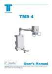
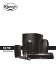
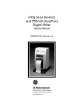
1
Model PXS-710D Podiatry X-Ray System Installation/Operation Manual Rev. 4 (S/N 140 - …) Manufactured By Source-Ray, Inc. 50 Fleetwood Court Ronkonkoma, NY 11779 Model: PXS-710D Section 1 SECTION PAGE I 1.1 GENERAL INFORMATION Introduction 1 1.2 Description 1 1.3 Important Notice 1 1.4 Compliance Notice 2 1.5 Safety Standards 2 1.6 Electrical Specifications 2 1.7 X-Ray Tube Characteristics 5 1.8 Mechanical Specifications 7 1.9 Labeling 8 II 2.1 INSTALLATION AND CALIBRATION Un-packaging 12 2.2 System Assembly 14 2.3 Electrical Connections 14 2.4 Calibration Set-Up 17 2.5 Tube Potential (kVp) and Beam Current (mA) 17 2.6 mAs 25 2.9 Beam Alignment 26 III 3.1 OPERATION Controls and Indicators 27 3.2 System Base Assembly 31 3.3 Operating Procedures 35 3.3.1 Manual Operation (Option RC-115) 35 3.3.2 Integrated Operation (OpalRad) 36 3.4 Faults 42 3.5 Operating Procedures (Support Base) 43 I Model: PXS-710D Section 1 IV THEORY OF OPERATION 4.1 System Overview 46 4.2 Generator/Control Assembly 46 4.3 OpalRad RS-232 Interface 48 V MAINTENANCE 5.1 Introduction 53 5.2 Recommended Intervals 53 5.3 Ordering Information 53 5.4 Maintenance / Cleaning Procedure 54 PAGE LIST OF FIGURES FIGURE DESCRIPTION PAGE 1.0 Focal Spot Dimensions 9 1.1 System Dimensions 10 1.2 Rating Chart, X-Ray Tube 11 1.3 Cooling Curve, Tube Head Assy. 12 2.1 System Assembly 17 2.2 Calibration Menu 20 2.3 Password Dialog Box 21 2.4 Calibration Menu 21 2.5 Calibration wizard 23 2.6 Settings Confirmation 23 2.7 Settings Saved Confirmation 23 2.8 Application Exit 24 2.9 Calibration Mode Selection 24 2.10 Calibration Mode 25 2.11 Ready Indicator 25 2.12 X-Ray Indicator 26 3.1 Generator/Control Connector Descriptions 30 II Model: PXS-710D Section 1 LIST OF FIGURES (Continued) 3.2 Control Panel Descriptions 30 3.3 Optional Remote Control Panel Descriptions. 31 3.4 Hand Switch Assembly 31 3.5 System (Front View) 32 3.6 System Base Rear Connector Descriptions. 35 3.7 System Base Side Connector Descriptions 35 3.8 OpalRad Study List 38 3.9 OpalRad patient Entry 38 3.10 OpalRad Acquisition Screen 39 3.11 OpalRad Generator Controls 40 3.12 OpalRad kVp Change 40 3.13 OpalRad mAs Change 41 3.14 OpalRad Ready Indicator 42 3.15 OpalRad X-Ray Indicator 42 3.16 OpalRad Ready Time Display 42 4.3 Generator OpalRad Communications 53 LIST OF TABLES TABLE DESCRIPTION PAGE 3.1 Technique Chart 25 4.3 Approved 3rd Party Control Software 49 4.4 RS-232 Connecter Pin-out 50 5.1 Maintenance Checklist 56 5.2 Displayed Fault Conditions 57 5.3 Warranty Statement 58 LIST OF SCHEMATICS P/N DESCRIPTION PAGE 100208 Schematic, Top Level System 54 100206 Schematic, Generator 55 III Model: PXS-710D Section 1 LIST OF SYMBOLS Symbol DESCRIPTION Exposure Switch For Human Use Protective Earth Attention, Consult Accompanying Documents Pinch Point, Keep Hands Clear Prescription Use (Part 21 CFR 801 Subpart D) Only Rev 0 1 2 3 4 REVISION CONTROL Description Initiated By Date Initial Release M. Eder 11/25/13 Corrected typos R. Manez 12/4/14 Updated Fig 3.5, Corrected callout ID’s M. Eder 1/13/15 Updated un-packaging procedure S. Lopez 2/6/15 Updated drawings for yoke pivot S. Lopez 5/5/15 IV Approved By R. Manez V. Milonas V. Milonas R. Manez R. Manez Date 12/20/13 12/5/14 1/13/15 2/6/15 5/6/15 Model: PXS-710D Section 1 GENERAL INFORMATION 1.1 INTRODUCTION This manual is divided into five sections and contains the following information: Section I describes general information, Section II contains installation and calibration procedures. Section III contains operating procedures and technique guides. Section IV discusses theory of operation and Section V contains maintenance procedures and recommended intervals. 1.2 DESCRIPTION The Model PXS-710D podiatry x-ray system is designed and manufactured by Source-Ray, Inc. It provides high quality radiographic capability in a lightweight small format. It is a component system consisting of the following items: Model:PXS-710D-CG X-Ray Control/Tube Housing Assy. Model:PXS-710D-S Podiatry Support Platform 1.3 IMPORTANT NOTICE The equipment manufactured by Source-Ray, Inc. and covered in this manual will function properly when operated, maintained, and repaired in accordance with the instructions in this manual. Source-Ray, Inc. does not assume responsibility for any malfunctioning of this equipment resulting from improper operation, maintenance, repair, or modification of its components. This equipment can be hazardous to both patient and operator unless established safe exposure factors are observed. Source-Ray, Inc. disclaims all responsibility from any injury resulting from improper application of this equipment. 1 Model: PXS-710D 1.4 Section 1 COMPLIANCE NOTICE The Source-Ray Model PXS-710D you have purchased has been designed, manufactured and calibrated to comply with the governing Federal Regulations 21 CFR Subchapter J. The maintenance schedules included are crucial to the continued reliability of this equipment with respect to regulatory compliance. Prescription Use (Part 21 CFR 801 Subpart D) Only Class I – Intermittent Mode PXS-710D System consisting of: X-Ray Control/Tube Housing Assy.: Model PXS-710D-CG Specified Range of Compliance: Tube Current: 10 mA Tube Voltage: 40 - 70 kVp mAs Range: 0.10 - 20.0 mAs 1.5 SAFETY STANDARDS The Source-Ray equipment you have purchased has been manufactured, and calibrated to meet the following safety standards: Model: PXS-710D-CG With Respect To Electric Shock Fire, And Mechanical Hazards Only designed, In Accordance With CAN/CSA C22.2 No. 601.1 UL 60601-1, IEC 60601-2-7 & IEC 60601-2-28 The Model PXS-710D is designed to comply with IEC 60601-1-2. 1.6 ELECTRICAL SPECIFICATIONS MILLIAMPERES Milliamperes will not deviate from the selected value by more than +/- 5% within the operating line voltage range and within the specified range of line voltage regulation. Measurements made with an Inovision mAs meter model 35035 or equivalent at 1.0 second. KILOVOLTS Kilovoltage will not deviate from the selected value by more than +/- 5% of full scale Measurements made with an Unfors Xi Mult-O-meter or equivalent. 2 Model: PXS-710D 1.6 Section 1 Continued: MAS MAS will not deviate from the selected value more than +/- 8% plus +/- 0.2 mAs within a range of 0.10 – 20.0 mAs. Measurements made with a Fluke Biomedical mAs meter model 35035 or equivalent. MAXIMUM RATING 10 mA at 70 kVp DC LINE VOLTAGE REGULATION 5% maximum as measured at the x-ray control panel at maximum rated output REQUIRED APPARENT RESISTANCE OF SUPPLY MAINS 115 ~ - 0.88 Ω MAXIMUM LINE CURRENT (10 mA at 70 kVp). Momentary: 13 A, Long Term: 4 A at 115 ~ (AC) Measurements made with a FLUKE 179 True RMS DVM and a FLUKE Y1801 clampon current probe adaptor. LINE VOLTAGE RANGE 115 ~ (103.5 - 126.5 AC) 50/60 Hz NOMINAL ELECTRIC POWER 700 Watt, Constant potential derived from a high frequency inverter system, Regulated for both kVp and mA. MINIMUM PERMANENT FILTRATION 1.8 mm of aluminum equivalent at 70 kVp 3 Model: PXS-710D 1.6 Section 1 Continued: SOURCE TO IMAGE DISTANCE (SID) Fixed: 30” AP, 36” Lateral REFERENCE CURRENT TIME PRODUCT (Power On Defaults) Beam Current: 10 mA Tube Potential: 60 kVp mAs Setting: 1.60 mAs LEAKAGE TECHNIQUE FACTORS Testing is performed at 70 kVp and 10 mA, 20 mAs exposure, every 1 minute. COOLING CURVES Automatic inhibit circuits provide a delay between exposures proportional to the exposure time. This delay is sufficient to allow proper tube cooling. The delay between exposures varies between 0.10 seconds and 20 seconds depending on the exposure time COLLIMATOR Manual Ralco R72 ENVIRONMENTAL Operating Temperature: 40 - 90 Deg. F. / 5 - 32 Deg. C Storage Temperature: 30 - 110 Deg. F. / -1 - 43 Deg. C 4 Model: PXS-710D 1.7 Section 1 X-RAY TUBE CHARACTERISTICS X-RAY TUBE TYPE SXR-90-15-0.5 ENVELOPE Hard glass. Borosilicate 0.085 thick. ANODE MATERIAL Tungsten target, copper plated and vacuum cast in copper. TARGET ANGLE 15 DEGREE. FOCAL SPOT 0.5 mm nominal as per N.E.M.A. XR-5. CATHODE Tungsten filament, line focus. INHERENT FILTRATION Minimum 0.65 mm aluminum equivalent at 80 kVp COOLING Natural convection through the insulating medium to the enclosure INSULATING MEDIUM Highly refined transformer oil; breakdown dielectric strength of not less than 45 kVp per ASTM D 877-49 X-RAY SHIELDING Approximate equivalent to .062 of lead for scatter radiation. MAXIMUM VOLTAGE 90 kVp 5 Model: PXS-710D 1.7 Section 1 Continued: MAXIMUM ENERGY 1.4 mA continuous at 90 kVp in cooled oil. Maximum temperature of oil not to exceed 70 degrees centigrade. THERMAL Oil insulation ANODE HEAT STORAGE 25,000 Heat Units ANODE COOLING RATE 200 Heat Units/Sec. NOTE: Heat Unit = kVp x mA (average) x 1 second 6 Model: PXS-710D 1.8 Section 1 MECHANICAL SPECIFICATIONS PODIATRY SUPPORT BASE Model: PXS-710D-S Aluminum Equivalence Table Top Material: Less than 1.2mm AL Physical Size: Length 33.7 in. 85.6 cm Width 39.8 in. 101 cm Gross Weight: 113 lb., 51.2 KG Height 42.5 in. 108 cm Weight Capacity: 300 lbs, 136 KG X-RAY CONTROL/GENERATOR MODULE Model: PXS-710D-CG Physical Size: Length 12.6 in. 32 cm Gross Weight: 29 lb., 13.1 KG Width 10.1 in. 25.7 cm Height 13.2 in. 33.5 cm REMOTE CONTROL MODULE (Optional) Model: RC-115 Physical Size: Length 7.30” Width 3.30” 7 Height 1.14” Model: PXS-710D 1.8 Section 1 Labeling Control/Generator Label Certification Label X-Ray Tube Label Podiatry Base Label 8 Model: PXS-710D Section 1 Figure 1.0 Focal Spot Dimensions 9 Model: PXS-710D Section 1 Figure 1.1 System Dimensions 10 Model: PXS-710D Section 1 Figure 1.2 X-Ray Tube Rating Charts 11 Model: PXS-710D Section 1 Figure 1.3 Cooling Curve, Tube Head Assembly 12 Model: PXS-710D Section 2 INSTALLATION AND CALIBRATION CAUTION This Section Pertains To Authorized SRI Service Personnel Only The Podiatry Support Base contains a spring-loaded arm with 500 pounds of force. Never remove the X-Ray Head while the arm is in a position other than 90° (Vertical). 2.1 UNPACKAGING 1) Remove the top carton to expose the below contents; B B A 2) Remove the top polystyrene cushion (A), which secures the generator, and put aside. 3) Cut off the 3 cable ties located on the Patient Handrails (B). 13 Model: PXS-710D Section 2 WARNING: The Podiatry Support Base contains a spring-loaded arm with 500 pounds of force. 4) Lift the Arm (C) up 90° and remove the Patient Back Handrail (D) and put aside. D C E F 5) Remove the Patient Side Handrails (E) from the cushions and put aside. 6) Remove the back handrail cushion from the box. 7) Remove the Podiatry System (Model PXS-710D) from the box and put aside. 14 Model: PXS-710D 2.2 Section 2 ASSEMBLY (Reference Fig. 2.1) 1) Secure the Patient Side Handrails (A) to the left and right side of the Podiatry Base (B) from the outside using 4 ea. 1/4-20 x 2” SHCS. Tighten securely. 2) Secure the Patient Back Handrail (C) to the back side of the Podiatry Base (B) from the outside using 4 ea. 1/4-20 x 2” SHCS. Tighten securely. 3) Place the Podiatry Support Base (B) in its final location. 2.3 ELECTRICAL CONNECTIONS Caution Be certain that the primary power source (wall outlet) is the same rating as the voltage specified on the label, located on the under side of the Generator Assembly. Connect the following connections at the Control/Generator Assembly. The Base Cable Assembly attached to the Boom Arm Assembly provides connection to the System Base assembly. Ref Fig. 3.1 1) Connect the power cord from the Base cable assembly to the power Inlet (2). 2) Connect the Remote Control Interface cable from the Base cable assembly to the Interface connector (5). 3) Connect the Exposure Switch from the Base cable assembly to the Exposure connector (3). 4) Connect the RS-232 Cable from the Base cable assembly to the RS-232 interface connector. (6) 15 Model: PXS-710D 3.1 Section 2 Continued: Connect the Following System Base connections. Ref Fig. 3.5 & 3.6 5) Connect the power cord from the Base cable assembly to the power Inlet (D). 6) Optional, Connect the Remote Control Interface cable from the Base cable assembly to the Interface connector (B). 7) Connect the Exposure Switch from the Base cable assembly to the Exposure connector (G). 8) Connect the RS-232 Cable from the Base cable assembly to the RS-232 interface connector. (A) 16 Model: PXS-710D Section 2 C A C B Figure 2.1 System Assembly 17 Model: PXS-710D 2.4 Section 2 CALIBRATION SET-UP Connect the mAs meter to the phone jack (J3) located on the top back plate of the Control/Generator Assy. Place the kVp meter (Unfors model 514L) in the X-Ray field @ 30” SID, and run calibration procedure. Connect an Oscilloscope to TP7 and TP8 (GND) on the Control Board 950132. 2.5 TUBE POTENTIAL (kVp) and Beam Current (mA) 1) Micro-controller operational modes: Manual Operation Mode Calibration Mode 2) Manual Operation This is the default mode of operation, which normally appears immediately after the Power On Self Test (POST). To adjust kV output, use the kV Up and kV Down keys. To select mAs setting, use the mAs Up and mAs Down Keys. 3) Calibration Mode (with Optional Remote Control RC-115) To enter the Calibration Mode, Connect the Remote Control RC-115. Turn the unit ON and press “kV Up”, “Reset”, and “mAs Up” simultaneously and hold for approximately 10 seconds during the POST condition. The display will show 710, wait for the ‘Chirp’ and then release the keys. Successful entrance into the calibration mode will result in the following displays kVp: “710”, mAs: “1.00” (or whatever the current firmware version is e.g.; “2.10”). Hold “kV Up”, “Reset”, and “mAs Up” for approximately 4 seconds to enter the calibration mode. There are eight 40kVp Preheat, 50kVp Preheat, 60kVp Preheat, 70kVp Preheat, Calibration adjustments: kVp kVp kVp kVp The displays will then change to; kVp: “04”, mAs: “0 – 255”, indicating that the system is ready to calibrate the 40kVp Preheat setting. 18 Model: PXS-710D Section 2 Calibration Mode RC-115 (Continued) a. Make an exposure and measure the actual mA waveform on the Oscilloscope. b. To increase or decrease the Preheat, Press kV up or down. Each activation of the button increases or decreases the Preheat. The number displayed in the mAs window represents a digital code for Preheat reference and is increased or decreased by one with each activation of the kV switches. Adjust the Preheat until the mA waveform is square with as little overshoot or undershoot as possible. c. When the calibration is completed for the 40 kVp Preheat range, depress the “RESET” to move to the kVp adjustment. The display will show 05. d. Place a Non-invasive kVp detector in the X-Ray Beam. e. Make an exposure and measure the actual kVp. f. To increase or decrease the kVp, Press kV up or down. Each activation of the button increases or decreases the kVp approximately 05. kVp. The number displayed in the mAs window represents a digital code for kVp reference and is increased or decreased by one with each activation of the kV switches. Adjust the kVp until the Actual kVp is within specifications. g. When the calibration of kVp is completed for the 40 kVp range, depress the “RESET” to move to the adjustment. h. Repeat steps a – g for the 50, 60 and 70 kVp ranges. The Display will show 04,05,06,07 for the Preheat adjustments and 40,50,60,70 for the kVp adjustments. i. Press RESET until the kVp Display shows ‘60’ j. Reset the MAS Meter to Zero k. Make an Exposure and measure the actual mAs l. Observe the reading on the MAS meter. The reading should be 1.0mAs +/5%. If adjustment is required, adjust R102 on the Control board assembly. Inspect squareness of wave-shape and repeat steps b - h above if necessary. m. When calibration is complete Recycle power to the unit to return to normal operation mode 19 Model: PXS-710D Section 2 4) Calibration Mode (with PXS-710D Calibration Utility) The PXS-710D Calibration Utility allows calibration of the PXS-710D with a host computer connected to the Serial RS-232 Port of the Generator. The PXS-710D Calibration Utility CD-ROM is provided with this documentation. Run the installation program and install the Utility. The Default Serial COM port is COM1, be sure to configure the Host PC accordingly. a. Start the PXS710D utility, PXS710D.exe . Located in the following directory: C:\Program Files\PXS-710D\ b. From the Drop-down menu select ”Cal Utils” as shown in fig. 2.2 below. Figure 2.2 Calibration Menu c. The Calibration Menu is password protected. In the password Dialog enter “yarx”. Fig, 2.3 20 Model: PXS-710D Section 2 Figure 2.3 Password Dialog Box d. Select ‘‘Re-Calibrate XRay Controller’’ from the Calibration Menu. Click ‘Run’ to enter the Calibration wizard. Ref Fig. 2.4 Figure 2.4 Calibration Menu 21 Model: PXS-710D Section 2 e. The Calibration Displays the Current Calibration point, kVp, mA and Time. Ref. Fig. 2.5 Figure 2.5 Calibration Wizard f. Make an exposure and measure the actual mA waveform on the Oscilloscope. g. To increase or decrease the Preheat, use the ‘Filament Preheat adjust’ slider to adjust Preheat up or down. The number displayed in the Preheat Raw window represents a digital code for Preheat reference and is increased or decreased by the slider control. Adjust the Preheat until the mA waveform is square with as little overshoot or undershoot as possible. h. Make an Exposure and verify the actual mA waveform on the Oscilloscope, Repeat step g if more adjustment is required. i. To increase or decrease the kVp, use the ‘kV adjust slider’ to adjust kV up or down. The number displayed in the kV Raw window represents a digital code for kVp reference and is increased or decreased by the slider control. Adjust the kVp until the Actual kVp is within specifications. j. Make an Exposure and verify the actual kVp value, Repeat step i if more adjustment is required. k. Using the attached mAs meter, measure the mAs for the 1 sec. exposure. Verify that the reading is 10.0 mAs (1.0 mAs +/- 5%). If adjustment is required, adjust R102 on the Control board assembly P/N 950132. Inspect squareness of wave-shape and repeat steps f - g above if necessary. 22 Model: PXS-710D Section 2 l. When the calibration is completed for the 40 kVp Preheat range, depress the “NEXT” button to move to the next calibration station. Repeat steps f – k. This process is repeated for 50, 60, and 70 kVp, as displayed in the kV window. m. Once the 70 kVp station is calibrated, pressing “NEXT” results in a confirmation dialog as in fig 2.6. Click on the ‘OK’ button to proceed. Figure 2.6 Settings Confirmation n. Once the new calibration settings are saved, a confirmation dialog is displayed. Click on ‘OK’ to proceed, you will be returned back to the “Calibration Menu”. Ref fig 2.7 Figure 2.7 Settings Saved Confirmation 23 Model: PXS-710D Section 2 o. Exit the ‘Calibration Menu’ by clicking ‘EXIT’. Ref fig 2.8 p. Exit the PXS710D.exe Calibration Utility by selecting ‘File->Exit’ from the drop down menu. Figure 2.8 Application Exit 5) Normal Operation (with the PXS-710D Calibration Utility) The PXS-710D Calibration Utility can be used as a standalone controller for the PXS-710D allowing setting kVp, mAs and manual Exposure control. a. Start the PXS710D Utility, PXS710DCal.exe . Located in the following directory: C:\Program Files\PXS-710D\ b. From the Drop-down menu select, ”Cal Mode” as shown in fig. 2.9 below. Figure 2.9 Calibration Mode Selection 24 Model: PXS-710D Section 2 c. Cal Mode adds addition diagnostic information to the application window. Ref fig. 2.10. This information is shown once the PREP switch on the Exposure switch is depressed. 1) Firmware revision 2) Controller state 3) Firmware CRC Figure 2.10 Calibration Mode d. kVp adjustment is accomplished by the UP and DOWN buttons located under the kVp display. e. Time/mAs adjustment is accomplished by the UP and DOWN buttons located under the Time Display. f. To Prepare the Generator, press the Exposure switch’s PREP button. A 2 second PREP display will be shown and turn GREEN when the unit is ready to Expose. Ref Fig. 2.11 Figure 2.11 Ready Indicator 25 Model: PXS-710D Section 2 g. To Make an X-Ray Exposure in the Cal Mode, press the EXPOSE button on the Exposure switch. Hold for the length of the exposure. Once the Exposure ends, release both the PREP and EXPOSE buttons on the Exposure switch. An Exposure indicator will be displayed for the duration of the exposure. Ref fig 2.12. A XRAY indicator is present on the main application window as well. Figure 2.12 X-ray Indicator h. When the ‘Cal Mode’ is no longer required, Select ‘File->Exit’ from the drop down menu. 2.6 mAs Measure the mAs using the mAs meter and confirm accuracy as indicated on checklist. 26 Model: PXS-710D 2.7 Section 2 BEAM ALIGNMENT Tighten yoke block to prevent movement during alignment. Rotate Collimator so that the knobs are facing front and tighten lock. Remove the collimator outer shroud by removing the 4 screws securing the shroud to the collimator. Place the phosphor screen in the beam at 30.6" and collimate field just to the outside edge of the middle 5” x 7” rectangle. Place Beam Alignment Tool in center of field (center dot at intersection of center lines) and adjust beam so that shadow of upper dot covers lower dot. Readjust borders if necessary. Set the Control Module to 70kV, 20.0 mAs. Take an exposure while observing the XRay field through the lead glass window of the test cabinet. Note the difference observed between the light field and the X-Ray field for further adjustment. If the centers are too far out of alignment, adjustment of Collimator light field is necessary. To adjust the horizontal position of the light field, rotate the unit 180 degrees to gain access to the mirror adjustment hardware. Loosen the locking screws sufficiently so as to allow the turning of the adjuster cam. Lock the fixing screw and cam after adjusting the mirror position. To adjust the vertical position of the light field, remove the lamp heat dissipater taking care to avoid being burned, as the dissipater can be very hot. Loosen the two lamp support fixing screws and using the hexagonal screw on the side of the lamp, adjust the lamp in the desired direction. Tighten the four screws fixing the lamp support. Finally, to adjust the brightness at the edges of the light field, loosen the screws fixing the screen to the lamp holder, and using an Allen screws, move the screen to obtain the desired adjustment. Tighten the screen fixing screws. 27 Model: PXS-710D Section 3 UNIT OPERATION 3.1 CONTROLS AND INDICATORS DESCRIPTION FUNCTION 1) POWER ON SWITCH Rocker type switch that controls the CIRCUIT BREAKER primary power into the system. Operating the switch turns the unit on. Power should not be turned on until the generator is ready for use. Circuit breaker will trip if excess current is drawn. 2) A.C. INPUT CONNECTOR Connects Control/Generator Assembly to supply mains. 3) EXPOSURE SWITCH CONN Connects the exposure switch to the Control/Generator Assembly. 4) MA TEST JACK Test point for mA during the calibration mode. 5) CONTROL CONNECTOR Connects to the optional Wall Mount Control Module. 6) RS-232 CONNECTOR RS-232 Communications for Remote Host Control via OpalRad or other control program. 7) kVp METER A digital LED meter that indicates the kVp prior to exposure. 8) MAS METER A digital LED meter that indicates the computed MAS prior to exposure. 9) KVP ADJUST Two momentary switches that adjust the kVp from 40 to 80 kVp in 1 kVp increments. 10)MAS ADJUST Two momentary switches that adjust the MAS up or down from 0.1 to 30 mAs. 28 Model: PXS-710D Section 3 11) READY INDICATOR Color GREEN per 60601-1 3rd Ed. Illuminates when unit is ready foroperation. Automatically prevents excessive operation by means of a time delay circuit. 12) X-RAY ON INDICATOR Color YELLOW per 60601-1 3rd Ed. Illuminates when exposure switch is depressed to indicate that x-ray’s are being produced for the pre-set time interval. In addition, an audio tone is generated at the same time. 13) FAULT INDICATOR Color RED per 60601-1 3rd Ed. A lamp that illuminates to indicate that a fault condition has occurred. Refer to table 5.2 for a description of fault conditions. 14) RESET BUTTON Clears and resets the front panel controls in the event of a fault condition (reference Table 5.2) 15) ANGLE INDICATOR A Angle indicator for the Horizontal Axis of the Generator position. 16) HAND SWITCH A two-position switch that controls the x-ray output. The first position is for prep (ready) light goes out and comes back on when unit is prepped), the second position is for x-ray (x-ray light comes on while x-rays are being produced). Premature release of the exposure switch will terminate the exposure and light the fault lamp. Depress the RESET button to clear the fault and Reset the timer. NOTE: Internal fuses provide protection for auxiliary DC circuits; replacements should be made by Authorized Source-Ray Personnel only. 29 Model: PXS-710D 3.1 Section 3 Continued: 4 1 6 2 5 3 Figure 3.1 Generator/Control Connector Descriptions (Generator Bottom View) 11 12 13 15 Figure 3.2 Control Panel Descriptions 30 Model: PXS-710D 3.1 Section 3 Continued: 7 8 11 12 9 13 14 10 Figure 3.3 Optional Remote Control Panel Descriptions 16 Figure 3.4 Hand Switch Assembly 31 Model: PXS-710D 3.2 Section 3 System Base DESCRIPTION FUNCTION A) BOOM ARM Controls the angle adjustment of the Generator/Control Assembly. B) SHUTTER KNOBS Adjusts X-Ray field size. C) PATIENT SUPPORT RAIL Functions as a support point for patients. D) PATIENT BASE Functions as positioning area for patient. E) DETECTOR SLOT Functions as a positioning slot for the 20/20 imaging detector. One is provided for Vertical alignment. Another is provided for Horizontal alignment. F) COLLIMATOR LAMP Left and Right buttons are provided on the Collimator. Depressing any button activates/de-activates the lamp, which is automatically extinguished after approximately 20 seconds to extend bulb life. G) SLIDE HANDLE Slide Handle for Opening and Closing the Vertical DETECTOR SLOT. 32 Model: PXS-710D 3.2 Section 3 Continued: C C F B A D G C E E Figure 3.5 System (Front View) 33 Model: PXS-710D 3.2 Section 3 Continued: DESCRIPTION FUNCTION H) PANEL POWER SWITCH Power Switch for the Imaging Panel Power Supply. J) RS-232 CONNECTOR Pass-Thru connector for the RS-232 port for Generator control by a Host Application. Provides connection to the Control/Generator RS-232 Port. DB9 FEMALE K) REMOTE CONNECTOR Pass-Thru Connector for the Optional Remote Control RC-115. Provides connection to the Generator/Control’s Remote port. RJ45 L) USB Pass-Thru USB A-B Connector for the 20/20 Imaging Panel. Provides a USB ‘B’ type connector for connection to the 20/20 imaging panel. M) POWER CONNECTOR IEC C14 Style AC Power Input Connector. N) GENERATOR CABLE Fixed cables. Generator/Control cables. P) 20/20 IMAGING PANEL P/T Pass-Thru Cable Grommet for the 20/20 Imaging Panel cable assembly. R) EXPOSURE SWITCH Exposure Switch Pass-thru Connector. Connects to the Generator/Control’s Exposure switch connector. RJ12 34 Model: PXS-710D 3.2 Section 3 Continued: H J K L L M N Figure 3.6 System Base (Rear Connector Panel) P R Figure 3.7 System Base (Side Connector Panel) 35 Model: PXS-710D 3.3 Section 3 OPERATING PROCEDURES: Generator/Control Assembly CAUTION Do not attempt to connect or disconnect any interconnect cables Without disconnecting the mains supply first. 3.3.1 Manual Operation 1) Operate the “Power On” switch (1) to turn the primary power on. 2) Activate the “Collimator Lamp” (G) by depressing one of the push-buttons Optional RC-115 located on the left or right side of the collimator. The collimator lamp will automatically extinguish after a period of approximately 15-30 seconds to extend bulb life. 3) Collimate the light field to the area of interest by means of the shutter adjust knobs. 4) Manually select the desired kVp by means of the kVp adjust switches on the optional Remote Control RC-115 (9). 5) Adjust the “mAs” to the desired interval by means of the mAs selectors (10). The resultant mAs is displayed on the mAs meter (8). Reference Table 3.1 for standard techniques. 6) After the required warm up period, the “Ready” Indicator will illuminate. It will not be possible to operate the unit until this has occurred. If the unit has not been operated for a long period of time an additional 2-minute waiting period is recommended. 7) While holding the “Remote Exposure Control”, step at least 6 feet to side of side of the x-ray control/generator assembly. 8) Depress the “X-Ray Switch” to the first position (prep). The “Ready Light” will go off and come back on when the unit is fully prepped. 36 Model: PXS-710D 3.3 9) Section 3 Continued: Depress the “X-Ray Switch” to the second position for immediate exposure. An audio tone will sound in addition to the “X-Ray” indicator illuminating for the duration of the exposure. Releasing the “X-Ray” switch prior to the pre-selected interval will terminate the exposure, light the “FAULT” Indicator and display a fault condition (Ref. Table 5.2). NOTES: 1) Unless the x-ray generator is going to be immediately used again, the “Power ON” switch should be turned off. Leaving the unit turned on provides opportunity for an accidental operation. 2) If the unit is going to be operated again, an automatic inhibit circuit will allow the x-ray tube to cool in proportion to the exposure time to prevent damage to the x-ray tube from overheating. At the end of this cycle the “Ready” light will illuminate indicating an exposure can be made. 3.3.2 Integrated Operation (3rd party OpalRad Software) The Generator/Control can be integrated with 3rd party applications to provide Anatomical programming of the Generator techniques. OpalRad by Viztek is available to control the PXS-710D. Please reference the OpalRad user Manual for more information. 1) Open and Run the OpalRad study list application. 2) Login, with your credentials provided by your Administrator. 3) The StudyList displays a list of patients, both past studies and waiting studies are shown in the list. Please reference the OpalRad user Manual for more information on the Study list and its configuration. Ref Fig 3.7 37 Model: PXS-710D Section 3 Fig 3.8 OpalRad Study List 4) If there are no patients in the study list, click on “Create New Study”. 5) Enter Patient information in the New Study dialog. Ref Fig 3.8 Fig 3.9 OpalRad Patient Entry 38 Model: PXS-710D 6) Section 3 Click on “Acquire” to Open the Image Acquisition interface, OpalUAI. Ref Fig 3.9 Fig 3.10 OpalRad Acquisition Screen 7) Alternatively if patients are present in the study list, Select a patient from the list. 8) Click on the “Add New Image” button at the bottom of the screen. 9) In the OpalUAI, if a Study had been selected, the anatomical body part will have been selected. Skip to…#14. 10) If a New study was created, without a body part association. A body part should be selected. Select ‘Right’ or ‘Left’ from the family group. 11) Select a ‘View’ from the Region group. Eg; Foot 12) Select a ‘Part’ from the Part group. Eg; ‘Foot AP’ 13) Once a Part is selected the Generator technique is set with the technique associated with the Body Part. 39 Model: PXS-710D Section 3 14) The kVp selector shows the Currently selected kVp and the Generator kVp. Ref Fig 3.10 Fig 3.11 OpalRad Generator Controls 15) The mA selector shows the Currently selected mA and the Generator mA. ( The PXS-710D only has one setting of 10ma ) 16) The mAs selector shows the currently selected mAs and the Generator mAs. 17) The Time selector shows the currently selected Time and the Generator Time. 18) When any Technique is changed, the new technique is displayed in a Red color until the Generator has been updated, at which point it will be displayed in White. Ref Fig. 3.11 & 3.12 Fig 3.12 OpalRad KVp Change 40 Model: PXS-710D Section 3 Fig 3.13 OpalRad MAs Change 19) To Change the kVp Technique. In the kVp display, Click on the top arrow to increase the setting, Or Click on the Bottom arrow to decrease the technique. 20) To Change the mAs Technique. In the mAs display Click on the top arrow to increase the setting, Or Click on the Bottom arrow to decrease the technique. 21) To Change the Time Technique. In the Time display Click on the top arrow to increase the setting, Or Click on the Bottom arrow to decrease the technique. 22) When the Set Technique matches the Generator Technique, the On Screen Generator Controls will resemble Fig 3.10 23) Techniques may be changed before the Exposure, When a technique is changed the Set techniques will display Red until the Generator Syncs with the Opal UAI. This normally takes approximately 1 second. Ref Fig 3.11 and 3.12 24) To take an Exposure, press the two Position Exposure Switch to position 1, the ‘PREP’ position. The OpalUAI will Show a Prepare indicator, then after 2 Seconds show a Green Radiation Symbol to indicate that a Exposure can be taken. Ref Fig. 3.13 41 Model: PXS-710D Section 3 Fig 3.14 OpalRad Ready Indicator 25) To make an Exposure press the exposure switch to the second position ‘XRAY’ and hold for the length of the exposure. The OPALUAI radiation indicator will turn YELLOW to indicate an Exposure. Ref Fig 3.14 Once the exposure terminates, release the two stage exposure switch. Fig 3.15 OpalRad X-Ray Indicator 26) The OPALUAI will then Acquire and process the image from the digital detector. Please Refer to the OpalRad user Manual for more information. 27) The PXS-710D Generator requires a Ready wait time before another exposure can be made. The OPALUAI displays this time in a Gray/Red bargraph. Ref. Fig 3.15 42 Model: PXS-710D Section 3 Fig 3.16 OpalRad Ready Time Display 28) Once the image is acquired, either Accept or Reject the image. 29) Once Imaging is completed, Click on the ‘EXIT’ button to Exit the OPALUAI and return back to the Study List. Ref Fig 3.7 3.4 Faults: The PXS-710D, when it encounters a Fault condition, will alert the user. There are three ways a unit Fault may be displayed to the User. 1) Fault Indicator on Generator/Control Panel. 2) Fault Indicator on optional Remote Control RC-115. A Fault Code is also Displayed in the kVp display to indicate the fault. Ref Fig 3.3 & Table 5.2 3) Fault Reporting via the RS-232 Host Control interface. Please reference the PXS-710D Control interface documentation. All Faults may be Reset by Cycling AC Power to the Unit. For Item #2, The Optional Remote Control Provides a ‘RESET’ button. For Item #3, a Command may be sent from the Host to reset the PXS-710D. 43 Model: PXS-710D 3.5 Section 3 OPERATING PROCEDURE: 1) Podiatry Support Base Move the Boom Arm (A) to the desired position and release, the Boom Arm will retain the current position. The Boom Arm position range Left to Right is from -45° to 90°. Front and back position range is -2° to +15° 2) To change the angle of the Generator/Control Assembly, Rotate the Generator/Control Left 15° or Right 15°, Detents will hold the Generator/Control in -15°, 0, +15° increments. 3) To change the forward tilt of the Generator/Control Assembly, push the top of the generator back to move the X-Ray field forward. Detents are provided at 0° and 15°. 4) To Place the Detector in the Vertical Detector slot, Pull on Slide Handle (G) to open Detector Slot, and insert Detector. Remove Detector and Push on Slide handle (G) to Close Detector Slot. 44 Model: PXS-710D Section 3 TABLE 3.1 TECHNIQUE CHART Examination Foot Dorso-plantar (AP) Lateral Marked Lesion Lateral Oblique Medial Oblique Axial Calcaneal Axial Sesamoid Harris and Beath Lewis Causton Ankle Anterior-Posterior Lateral Lateral Oblique Medial Oblique Mortise Stress Views (AP, lat) Holly Isherwood Broden Examination Foot Dorso-plantar (AP) Lateral Marked Lesion Lateral Oblique Medial Oblique Axial Calcaneal Axial Sesamoid Harris and Beath Lewis Causton Ankle Anterior-Posterior Lateral Lateral Oblique Medial Oblique Mortise Stress Views (AP, lat) Holly Isherwood Broden XM3 PDR (Naomi): 400 speed. Thickness KVP MAS SID Normal Normal Normal Normal Normal Normal Normal Normal Normal Normal 55 55 55 55 55 55 55 55 55 55 -60 -60 -60 -60 -60 -60 -60 -60 -60 -60 1.5 1.5 1.5 1.5 1.5 4.5 4.5 4.5 3.0 3.0 30” 36” 30” 36” 30” 30” 30” 30” 30” 30” Normal Normal Normal Normal Normal Normal Normal Normal Normal 55 55 55 55 55 55 55 55 55 -60 -60 -60 -60 -60 -60 -60 -60 -60 3.0 3.0 3.0 3.0 3.0 1.5 1.5 1.5 3.0 30” 36” 36” 30” 30” 30”/36” 36” 36” 36” CR (Generic): 150 speed. Thickness KVP MAS SID Normal Normal Normal Normal Normal Normal Normal Normal Normal Normal 55 55 55 55 55 55 55 55 55 55 -60 -60 -60 -60 -60 -60 -60 -60 -60 -60 5.5 5.5 5.5 5.5 5.5 5.5 5.5 5.5 5.5 5.5 30” 36” 30” 36” 30” 30” 30” 30” 30” 30” Normal Normal Normal Normal Normal Normal Normal Normal Normal 55 55 55 55 55 55 55 55 55 -60 -60 -60 -60 -60 -60 -60 -60 -60 5.5 5.5 5.5 5.5 5.5 3.0 3.0 3.0 3.0 30” 36” 36” 30” 30” 30”/36” 30” 30” 30” 45 Notes Notes Model: PXS-710D Section 3 Harris Axial projection of the heel is useful for demonstrating talo-calcaneal bars. Patient stands with both feet on the film. The patient leans forward slightly. The tube is positioned behind the patient and the central ray is angled 45 degrees towards the heels and is centered between the medial malleolus. Lewis Method The routine view of the Sesamoid bones of the first metatarsal. Isherwood Methods (subtalar region) 1) Projection to demonstrate the anterior subtalar articulation. Medial border of the foot at a 45-degree angle to the cassette. Center 2.5cm distal and 2.5cm anterior to the lateral malleolus. 2) Projection to demonstrate the middle articulation of the subtalar joint and give an end-on view of the sinus tarsi. Foot in the AP ankle position, rotate the ankle 30 degrees medially. Center to a point 2.5cm distal and 2.5cm anterior to the lateral malleolus with a 10 degree cephalad angulation. 3) Projection to demonstrate the posterior articulation of the subtalar joint in profile. Foot in the AP ankle position. Rotate the ankle 30 degrees laterally. Center to a point 2.5cm distal to the medial malleolus with a 10-degree cephalad angulation. 4) Broden I Subtalar joint view. Foot positioned as for AP ankle, then rotate the foot 45 degrees medially. Angled the tube cranially between 10 degrees and 40 degrees. Broden II Subtalar joint view. Foot positioned as for AP ankle, then rotate the foot 45 degrees externally. Angle the tube cranially 15 degrees. Causton Method Oblique foot projection to demonstrate the sesamoids. Position foot laterally, with the medial side against the cassette. Angle the central ray 40 degrees towards the ankle and center to the first metatarsophalangeal sesamoids. 46 Model: PXS-710D Section 4 THEORY OF OPERATION 4.1 SYSTEM OVERVIEW The Model PXS-710D incorporates Control/Generator Assembly. one major electrical assembly, the The Control/Generator Assy. consists of five sub- assemblies. The generator assembly houses the high voltage circuitry and the xray tube, high frequency generating circuitry, control electronics, microprocessor and a collimator (beam limiting device) assembly. The PXS-710D also can be controlled via a RS-232 Serial link, the RS-232 Serial link allows a 3rd party computer application, OpalRad, to communicate with the generator. 4.2. GENERATOR/Control ASSEMBLY The Generator Assembly is made up of High Voltage multipliers for the anode and cathode supplies, voltage feedback dividers, high voltage transformers and the filament transformer. For the Low Voltage section a Control Microprocessor PWA, Power Board PWA and the 24V power Supply are used. The voltage used to generate the high voltage enters the assembly at pins 1 & 7 of connector P1. The voltage is approximately 650 VPP at an approximate 30 kHz square wave, for a 70-kVp output. The filament voltage enters at pins 2, 4 & 6 of connector P1. Pin 4 is at a DC level of approximately 24V, and pins 2 & 6 have a high frequency voltage of about 48 VPP at approximately 50 KHz with respect to ground. Pin 3 & 5 of P1 are ground connections. Pin 9 of P1 is the kV feedback signal (10 V=100kV). Pin 10 of P1 is the cathode low-end signal (10V = 10mA). Pins 11 of P1 provides the anode low-end signal, which goes to the mA test jack. Connector J3 (mA test jack) places a mA meter in series with the mA line for calibration purposes (Ref. Section 2.3). 47 Model: PXS-710D 4.2 Section 4 Continued: The Power Board Inverter Assembly is powered by 115 VAC or 230 VAC via connector TB1 (ref dwg. 100206). With circuit breaker CB1 closed, an AC voltage is applied through current limiting resistor R1 of the Power Board PWA. The voltage is then rectified and filtered via Diode Bridge D1 and Capacitors C1 – C2. The DC Voltage is used as the “Rail Voltage” for the High Frequency Drive to the X-Ray Generator. Relay K1, contacts 1A and 1B short resistor R1, on the Power Board PWA, during the Prep and X-ray period to allow the line to deliver the required power. Transistors Q1 and Q2 of the Control/Generator Assembly make up a full bridge high frequency circuit operating at approximately 30 kHz. This circuit is energized during the X-Ray On period and is used to convert the DC voltage back to high frequency AC to drive the high voltage transformer in the generator assembly (approx. 30 kHz). The Control Board PWA provides commands to the Power Board PWA electronics for the kV reference, filament pre-heat, exposure time… and monitors the system for faults. U15 of the Control Board PWA provides the High Frequency Drive for the High Voltage Supplies (anode & cathode), it drives the pulse transformer T1 through signal FET’s Q4 & Q6. Transformer T1 drives the Gate of the IGBT’s, Q1 & Q2 located in the Power Board Assy. U16 of the Control Board Assy. supplies the High Frequency Drive for the filament circuitry by driving FET’s Q8 & Q9 on the Power Board PWA. These FET’s provide the High Frequency voltage for the filament transformer T1 of the Generator Assy. Current transformer T4 of the Power Board PWA monitors the primary current to the High Voltage Transformers and triggers timer IC/U13 which sends a fault to the Microprocessor and shuts down the High Frequency Generator IC/U15 which in turn shuts down the High voltage IC’s. 48 Model: PXS-710D 4.2 Section 4 Continued: IC/U18A (Over Voltage Comparator) and IC/U17A & U18 (Over Current Comparator) shut the High Voltage down in the event of an over-voltage or overcurrent condition. A fault signal is also sent to the Microprocessor. IC/U19 is the DC-DC converter that converts the 24VDC to +/-15VDC for the low voltage signal processing electronics. Power Supply A1 on the Power/Control Assy. provides the +24VDC for all electronic and microprocessor circuitry. 4.3 OpalRad Rs-232 Interface The RS-232 Serial Link allows a 3rd party application to control the Generator. Generator settings such as kVp, mAs can be set by the 3rd party application. The complete protocol is available from Source-Ray Inc. upon request. The following applications have been validated to operate with the PXS-710D: Manufacturer Product UAI Version Viztek OpalRad 2.3.4.24 Table 4.3, Approved 3rd Party Control Software The Serial hardware in the PXS-710D generator uses a 2.5KV Optically Isolated EIA/TIA-232E Compatible 3-wire interface. (Ref Figure 3.1 Item 6) This interface Operates at 19200 BAUD, 8N1. The Pin assignments are listed in Table 4.4 49 Model: PXS-710D Section 4 Pin # 1 2 3 4 5 6 7 8 9 Function Description N/C TX RX N/C GND N/C N/C N/C N/C Signal Output Input Common Table 4.4, RS-232 Pin Out The Serial Protocol used in this interface incorporates a data packet with a 16bit CRC for error detection. Handshaking ACK and NAK replies are incorporated to enable error recovery. The Interaction of the OpalRad UAI (User Acquisition Interface) with the PXS-710D Generator is as follows: (ref. Figure 4.3) The OpalRad UAI will be referred to as the ‘Host’ Generator Idle When the generator is at rest, three (3) commands are recognized from the Host: SETGENCMD Sets the Generator Techniques UNSETGENCMD Revokes the Generator Techniques ERRORSTATUSCMD Requests the current machine status The SETGENCMD sets the Generator Techniques with the Data supplied in the data packet. When a user picks a technique button, this command is sent to the generator. The UNSETGENCMD revokes any set techniques by setting them to zero. This is sent to the generator when a Technique button is de-selected. 50 Model: PXS-710D Section 4 The ERRORSTATUSCMD Request is used for retrieving the Generator Techniques and obtaining Error information. It is also used to verify the Generator is properly connected and powered ON. The OpalRad UAI will process any Errors returned and display them to the User. These Errors are outlined in Table 5.2 Generator PREP If the generator enters the PREP state the following command is sent to the Host: PREGENCMD Indicates to the Host the PREP switch is activated. When the User depresses the PREP switch, the generator sends a PREGENCMD to the Host. This will alert the Host that the User is attempting to start the expose process. The Host will then Display a READY Icon to alert the User that a 2 second x-ray Tube filament heating time is in progress. After 2 seconds the Icon turns GREEN, indicating to the user that an exposure can be made. During the PREP and the following XRAY state, the Generator will not accept any commands and the set Techniques cannot be changed. Generator XRAY During the Exposure process the following commands are sent to the Host: XRAYINDCMD Indicates to the Host a X-Ray indicator is to be displayed. POSTGENCMD Indicates to the Host an exposure has completed. 51 Model: PXS-710D Section 4 Generator XRAY (Continued) When the User proceeds to depress the XRAY switch the generator sends a XRAYINDCMD to the Host. The Host then displays a X-RAY Icon to indicate to the User an exposure is in progress. The Generator will then make an exposure with the Techniques set in the Generator Idle state. If an Error Occurs or the User releases the PREP and/or XRAY switches the Exposure terminates. Otherwise the Exposure completes normally with the Techniques that were set. Once the Exposure is completed, a POSTGENCMD is sent to the Host. The POSTGENCMD contains the Techniques used for the exposure including Time. If the exposure terminated prematurely, the POSTGENCMD reports the actual exposure time and returns the Error that caused the termination. After the Exposure and when the User has released the PREP and XRAY switches, the Generator returns to the Generator Idle State. 52 Model: PXS-710D Section 4 Figure 4.3, Generator OpalRad Communications 53 Model: PXS-710D Section 5 UNIT MAINTENANCE CAUTION This Section Pertains To Authorized Source-Ray Service Personnel Only 5.1 INTRODUCTION In order to keep the Source-Ray unit operating properly, it must be inspected and checked in accordance with the recommended intervals depending on the age and use of the equipment. If there is a problem, call an authorized serviceman. DO NOT OPERATE THE EQUIPMENT UNTIL REPAIRS ARE COMPLETED. 5.2 RECOMMENDED INTERVALS Periodic preventive maintenance including cleaning, mechanical and electrical adjustments, are to be performed every Six months or 3000 exposures. The periodic maintenance schedule is required to maintain the unit in proper and accurate working condition. 5.3 ORDERING INFORMATION To order replacement parts contact your local authorized Source-Ray dealer. Authorized Source-Ray dealers should contact the main office at (631) 244-8200 between the hours of 8:00 AM and 5:00 PM. When ordering replacement parts be prepared to submit the following information: purchase order no. (If possible), Source-Ray part number, part description, quantity required and shipping instructions. If replacement parts are for a unit under warranty be prepared to submit model numbers and serial numbers to expedite your order. 54 Model: PXS-710D 5.4 Section 5 MAINTENANCE PROCEDURE Cleaning Procedure When cleaning, use a cloth moistened in warm soapy water (use mild soap). Do not soak the unit and do not use strong cleaners or solvents as they may blur the lettering or dull the finish. Polish with pure liquid or paste wax only. Do not use a wax containing a cleaning substance. Do not polish the meter windows. Disinfecting Procedure X-ray equipment and accessories should be properly disinfected immediately after use and before the next patient is attended to. A diluted solution of sodium hypochlorite should be routinely used for disinfecting x-ray equipment and accessories, especially those without stainless steel components. Radiographers should wash their hands after attending to a patient and before attending to the next patient. 55 Model: PXS-710D Section 5 TABLE 5.1 MAINTENANCE CHECKLIST MODEL: PXS-710D SERIAL # ___________ 1) Beam Current (Reference Section 2.3) ____________ 2) Tube Potential (Reference Section 2.4). ____________ 3) MAS (Reference Section 2.5). ____________ 4) Beam Alignment (Reference Section 2.6) ____________ 5) Check voltage on X-Ray Generator at J2 pins A and B (collimator supply) with collimator unplugged (24 VDC). ____________ 6) Check that all Indicator lights are operating. ____________ 7) Check that all hardware is tightly secured. ____________ 8) Check that collimator-mounting ring is tight. ____________ 9) Check all interconnect cables for broken or frayed wires. ____________ 10) Check that all hardware is secure and properly fastened. ____________ 11) Check that all friction locks (head rotation) are properly adjusted, tighten as required. 12) ____________ Inspect piston mounts. Make sure all mounting hardware is secure. (tighten if necessary) 13 ____________ Inspect piston strength, if unit drifts down when lock is not engaged, replace piston. ____________ Comments: _____________________________________________________________ _____________________________________________________________ _____________________________________________________________ _____________________________________________________________ SERVICE ENGINEER: ____________________ 56 DATE: _____________ Model: PXS-710D Section 5 TABLE 5.2 DISPLAYED FAULT CONDITIONS DISPLAY FAULT DESCRIPTION ACTION REQUIRED 1 Inverter Fault. Reset Unit (1), Call for Service 2 No or low mA signal during exposure Call for Service 3 Exposure terminated by operator Reset unit 4 Stuck or shorted exposure switch. Check or replace switch. 5 Reserved 6 Reserved 7 Reserved 8 Exposure watchdog failure Call for Service 9 Flash CRC Error Call for Service 10 RAM Memory Error Call for Service 11 EEPROM CRC Error Call for Service 12 EEPROM Write Error Call for Service 13 Serial Communications Error Reset unit 14 Stuck or Shorted Prep Switch Check or replace switch. NOTES: 1) May indicate a timer problem. Depress the reset button to clear the fault condition and continue. If the problem persists, call for service. 57 Model: PXS-710D Section 5 TABLE 5.3 Warranty Statement WARRANTY Source-Ray, Inc. warrants its Model PXS-710D Podiatry X-Ray System to be free of manufacturing defects, which can impair their normal operation when used within their specified ratings. Claims under this warranty must be made within 3 years after shipment from the factory. Such warranty shall not apply to defects resulting from accidents, alterations, abuse or misuse. Liability under this warranty is limited to repair or replacement of defective components at the factory. Shipping costs are not included. This warranty is in lieu of any other warranty expressed or implied. Collimator bulbs, exposure cord assemblies, interconnect cables and tires are considered normal wear and tear and are not covered under this limited warranty. 58 Model: PXS-710D Section 5 Rev. Description - Initial Release Date Init. 9/3/13 ME A2 P/N: 910303 PXS-710D BASE ASSY. A1 P/N: 20/20 IMAGING DIGITAL PANEL W2 EXPOSURE SWITCH A3-J5 RJ12 W3 AC POWER A3-J1 IEC W4 REMOTE CONTROL A3-J4 RJ45 W5 RS232 INTERFACE A3-J2 DB9 A3 P/N: 910298 PXS-710D GENERATOR GROMET BRN BLUE GRN/YEL J2 A1-J3 A1-J2 1 A1-J1 A1-1 TB1 1 2 3 BRN BLUE GRN/Y EL 1 2 3 W1 BRN BLUE GRN/Y EL 1 2 3 TO COMPUTER INTERFACE, DB9 J4 TO REMOTE (RC-115), RJ45 J3 TO COMPUTER INTERFACE, USB W1J1 AC POWER INPUT GND STUD J5 EXPOSURE SWITCH RJ12 A1-W1 CONNECTORS: W1 - 910XXX W2 - CAT3 W3 - AC POWER CORD, W4 - CAT5 W5 - DB9M/DB9F SERIAL CABLE (ASSMANN AK131-2-R) , 6' PHONE CORD, 8' 6' PATCH CABLE, 6' J1 J2 J3 J4 J5 - SRI P/N 500074 DGB9MF ECF504-BAS ECF504-R5E ECF504-6S Proprietary N ote Tolerences: Fractions +/- 1/64 59 Source-Ray, Inc. The inf ormation contained herein is conf idential and proprietary inf ormation of Source-Ray , Inc. which shall not be disclosed to any third party without the express prior written consent of Source-Ray , Inc. Decimals .xx +/-0.01 .xxx +/-0.001 50 Fleetwood Ct. Ronkonkoma, NY 11779 Drawn By : Date: M.EDER 9/3/13 Checked By : Date: Angles +/- 30' PXS-710D SCHEMATIC BASE WIRING DIAGRAM Material Drawing No N/A Approv ed By : Date: V. Milonas 10/3/13 Size B Rev . A 100208 Scale 1:1 Sheet 1 of 1 Model: PXS-710D Section 5 Rev. Description 0 Initial Release 1 2 3 HV B mAs JACK 1 2 3 A3TB2 A3TB1 HV A +24VDC PREP ARC POS ARC NEG IGBT DRV A IGBT DRV CT IGBT DRV B COMMON POWER BOARD/IGBT DRIVER ASSY: 950128 SCH: 100195 230V 115V 0V Init. ME W5J3 P/O W2 A3 3 2 1 Date 8/5/13 1 E7 HV A A3J1 1 W2J1 1 E1 HV B 1 2 3 4 5 6 7 8 E8 COMMON A5 A6 CONNECTOR BOARD ASSY: 950123 SCH: 100xxx 1 A2J6 1 1 A6P1 1 2 3 4 5 6 7 8 1 W2\J6 +24VDC PREP ARC POS ARC NEG IGBT DRV A IGBT DRV CT IGBT DRV B COMMON P/O W2 E11 ANODE LE E3 COMMON A2J3 E9 ANODE FB CATHODE LE ANODE FB FIL A COMMON FIL CT FIL B 1 2 3 4 5 6 E2 FIL A 1 E5 COMMON 1 E4 FIL CT 1 E6 FIL B W1 XRAY PREP RET PREP XRAY RET PREP XRAY PREP RET RS-232 COMMON COMMON RX TX +5VDC P/O W2 A2J4 E1 +24VDC +24VDC +24VDC COMMON COMMON COMMON A4J1 Display Board ASSY: 950131 SCH: 100200 CONTROL BOARD ASSY: 950132 SCH: 100196 E10 CATHODE LE W2J7 W3 A4 A2J8 A2J5 W2J8 TO EXPOSURE SWITCH A7 COLLIMATOR P/N: 400274 POS NEG GND 1 2 3 4 5 6 TO REMOTE INTERFACE P/O W1 ACL 24V @ 5.4A CN1 ASSY: 415020 POWER SUPPLY COM COM COM COM CB1A red +24V +24V +24V +24V CN2 W1L1 LINE FILTER 1 2 3 4 5 6 7 8 red blk P/O W2 grn/yel NEUTRAL LINE GROUND POWER IN CONNECTOR ACN brn blk A1 blue W2CN2 P/O A7 W1J1 TANK ASSY ASSY: 910295 SCH: 100194 1 A2J7 A2 ANODE LE CATHODE LE ANODE FB COMMON HV A FIL B COMMON FIL CT COMMON FIL A HV B CB1B P/O W1 Harness Assemblies: 1) W1 - 910299 2) W2 - 910300 3) W3 - 910301 Proprietary N ote Tolerences: Fractions +/- 1/64 60 Source-Ray, Inc. The inf ormation contained herein is conf idential and proprietary inf ormation of Source-Ray , Inc. which shall not be disclosed to any third party without the express prior written consent of Source-Ray , Inc. Decimals .xx +/-0.01 .xxx +/-0.001 Angles +/- 30' 50 Fleetwood Ct. Ronkonkoma, NY 11779 Drawn By : Date: M. Eder 8/5/13 Checked By : Date: Material V. Milonas 8/9/13 N/A Approv ed By : Date: V.Milonas 8/15/13 GENERATOR SCHEMATIC (PXS-710) Size C Drawing No Rev . 100206 Scale 1:1 Sheet 0 1 of 1 This Page Intentionally Left Blank 61