1
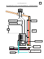
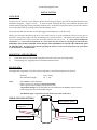
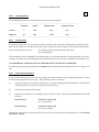
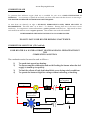
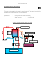
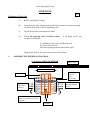
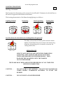
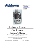
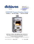
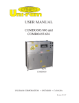
INSTALLATION AND OPERATING MANUAL
This manual MUST be read carefully
and all requirements carried
out to ensure satisfactory
performance
dickinson
since 1932
Dickinson Marine (1997) Ltd
407-204 Cayer Street,
Coquitlam, B.C. Canada
V3K 5B1
www.dickinsonmarine.com
E mail [email protected]
www.ahoycaptain.com
Quality and service is remembered long after price is forgotten
www.ahoycaptain.com
1
WARNINGS AND DISCLOSURES
FOLLOW ALL INSTALLATION AND OPERATING PROCEDURES
A PERMANENTLY OPEN FRESH AIR INLET MUST BE INSTALLED TO ALLOW AIR
TO ENTER THE BOAT AND PROVIDE COMBUSTION AIR FOR THE STOVE
THE DIESEL FUEL SUPPLY MUST BE FILTERED (The element or filter MUST be
changed every year)
A BAROMETRIC FLUE DAMPER MUST BE INSTALLED IN FLUE STACKS LONGER
THAN 6 FEET
DO NOT USE SUBSTITUTE PARTS
AFTER START-UP THE FLAME MUST BURN ABOVE THE 6" BURNER RING AT ALL
TIMES. THE FLAME MUST NOT BURN BELOW THE RING - INSIDE THE BURNER.
EXCESS HEAT AND RAPID CARBON BUILD-UP WILL OCCUR.
DO NOT OPERATE THIS PRODUCT UNATTENDED
LIGHTING INSTRUCTIONS
1.
2.
3.
4.
5.
6.
7.
8.
9.
Open the door
Turn the oil metering valve ON and allow about 30ml (2 tbls) of oil into the burner
TURN THE OIL METERING VALVE OFF
Light the oil with a piece of lighted tissue
Replace the top lid
Turn the COMBUSTION FAN to LOW SPEED
NOTE : If the flame goes out after this stage DO NOT RE-LIGHT FOR 15 MINUTES
The priming fuel will vaporize in 5-10 minutes. When priming fuel is almost gone
turn the OIL METERING VALVE ON to the lowest setting to BRING THE FLAME
ABOVE THE BURNER RING
When the flue stack is hot (15-20 mins) the COMBUSTION FAN may be turned OFF
kept on at low speed.
Keep at low fire for 30 minutes before selecting higher settings. INCREASE FUEL
ONE INCREMENT AT A TIME.
CAUTION
:
NEVER LIGHT A FLOODED BURNER
www.ahoycaptain.com
2
3" diameter DP Flue Cap
TYPICAL INSTALLATION
NEWPORT HEATER
3" Thru-Deck Fitting
Dress Ring
4 ft minimum
Max 45
degrees
Hot
Water
Outlet
3" diameter Pipe
Pressure Relief Valve
Barometric Draft Damper
Hot
Water
Tank
Cold
Water
Outlet
12"-24"
3/8" Vent
Gravity Fuel
Tank
Check
Valve
Water
Pump
Min 12"
Filter and
Shut-Off
Valve
Valve Fuel Level
3/8" Copper Fuel Line
From Main
Water Tank
To Main
Water Tank
Fuel Pump less than 4 psi
Overflow return to
main tank or container
Fuel from Main Tank
3
www.ahoycaptain.com
RECOMMENDED INSTALLATION REQUIREMENTS – NEWPORT HEATER
45 degree max Elbows
1/2" Spacers
3” Barometric Damper
12”
High Heat
Insulation
Stainless Wall Liner
Drip Tray
Permanently open
fresh air inlet
3/8”Copper Fuel Line
Overflow
www.ahoycaptain.com
4
INSTALLATION
LOCATION
The space for the location of your Newport heater must be large enough to provide the required clearances (see
installation diagrams - Pages 2 and 3).
It must be lined with high density, heat retardant insulation and
finished with a light gauge metal, preferably stainless steel. Particular care must be taken to protect the surfaces
close to the edge of the top cooking surface and the chimney stack.
The location should also take into account the length and configuration of the flue stack.
Ideally your Newport should face the bow or the stern however, in most installations, the stove faces port or
starboard. Fuel gravity feeds from the oil-metering valve into the burner. Should this valve drop below the
level of the burner fuel will not flow into the burner and the fire will go out. In a fore and aft SAILBOAT
installation or in a fore and aft installation in a boat which will list or heel for any length of time THE OIL
METERING VALVE MAY REQUIRE TO BE RE-LOCATED EXTERNALLY ON THE LEFT OR RIGHT SIDE
OF THE HEATER. If you have are in doubt regarding the need for a valve re-location please ask your dealer
or call dickinson on our 800 number.
MOUNTING AND SECURING
1)
2)
The heater must be and secured through the bolt holes on the rear mounting bracket.
The finishing tray (supplied) must be installed under the heater
FLUE STACK
The length and straightness of the flue stack are important to the efficient operation of the stove
Diameter
Recommended Length Notes -
3 ins (7.62cm)
3 ft ( 1m)
Stack must be correct diameter
Elbows in excess of 45 degrees not recommended
Elbows greater than 45 degrees MUST not be used.
A Barometric Damper is recommended for all installations but must be installed in flue
stacks longer than the recommended lengths
The ROUND pipe is squeezed to fit the OVAL flue collar on the stove
THROUGH DECK FITTING
Through Deck-Fitting
Gasket or Sealing
Compound
Teak Leveling Block
Internal Dress Ring
Deck
www.ahoycaptain.com
FLUE CAP
5
The Dickinson DP or H style flue caps are recommended. The location of the flue cap above deck must be clear
of any immediate obstruction that may cause unusual air movement or turbulence. CAUTION : The Flue Cap
gets hot when the stove is operating.
OIL - SUPPLY
Oil is supplied to the oil-metering valve of the heater from a gravity feed tank or by a low-pressure pump direct
from the main fuel tank. (See Typical Installation diagram - Page 2) UNDER NO CIRCUMSTANCES
MUST HOLES BE DRILLED IN THE DRIP PAN.
GRAVITY
A minimum head of fuel 12" (30.48 cm) above the fuel level
marked on the side of the oil-metering valve is required to operate
the oil-metering valve.
DO NOT USE A PRESSURIZED FUEL TANK.
The gravity feed tank must be vented and all fuel lines must be as
straight as possible to avoid air locks.
USE 3/8" (9.52 mm) COPPER FUEL LINE ONLY
PRESSURE
A low pressure pump (less than 4 psi) must be plumbed
directly from the main fuel tank. The fuel inlet is a 3/8" flare fitting.
DO NOT TAKE THE STOVE FUEL SUPPLY OFF THE ENGINE
SUPPLY OR RETURN LINE
USE 3/8" (9.52 mm) COPPER FUEL LINE ONLY.
A FUEL FILTER must be installed in the fuel supply line. THIS FILTER OR FILTER ELEMENT
MUST BE CLEANED OR REPLACED AT LEAST EVERY YEAR.
A POSITIVE SHUT-OFF VALVE MUST be located in the fuel supply line close to the stove.
OIL METERING VALVE
(See exploded view diagram - Page 6)
IMPORTANT NOTE : THE OIL METERING VALVE OVERFLOW MUST NOT BE
PLUGGED UNDER ANY CIRCUMSTANCES. A fuel line should be taken from the
overflow to a container situated away from the heats source. This tank should be checked
periodically for oil.
UNDER NORMAL OPERATING CONDITIONS NO FUEL WILL
ESCAPE THROUGH THE OVERFLOW. FUEL DRIPPING FROM THE OVERFLOW
INDICATES DIRT IN THE LINE. IF THIS HAPPENS THE STOVE WILL CONTINUE
TO BURN NORMALLY. THE OIL METERING VALVE REQUIRES CLEANING AND
REPAIR.
Thermal Mechanical
www.ahoycaptain.com
Safety Shut-Off
OIL METERING VALVE
5/64ths allen wrench
fuel flow adjusting
screw. Adjust from
top of knob.
6
5/64ths allen
wrench
securing screw
Metering Stem
Spring
Circlip
1/8"
NPT
Mesh Screen on fuel
"O"Ring
Metering Slot
Fuel Inlet
Needle
and Seat
3/8"Flare
Float
Float Hinge and
Needle Activator
Fuel Oil Level
Indication Bar
Fuel Oil
Level
Overflow
OverflowTube
Metering
Stem Guide
Safety Overflow to container
or back to main fuel tank
Fuel Outlet to
www.ahoycaptain.com
7
FUEL - CONSUMPTION
The Oil Metering Valve flow rate has been set at the time of manufacture.
_____________________________________________________________________________________
Low Fire
cc/minute
cc/hour
4
240
litres/24 hours
5.86
gallons/ 24 hours
1.29
High Fire
10
600
14.54
3.20
_____________________________________________________________________________________
FUEL - VARIATIONS
It is unlikely that the fuel you are using is the same viscosity as the fuel used to calibrate the oil-metering valve.
Fuel viscosity differs on a routine basis even though you purchase the same grade of oil from the same supplier.
Factors influencing oil viscosity :
Oil company quality adjustments and refinements
and oil temperature
The oil metering valve is calibrated for #2 diesel (unless you requested otherwise.) Burning diesel #1 (stove oil)
will allow 25% more fuel and burning kerosene will allow 50% more fuel to flow through the oil-metering valve.
IT IS IMPORTANT TO BURN THE FUEL FOR WHICH THE VALVE WAS CALIBRATED
By studying the burning characteristics (see Operation) it can be determined whether the fire is too high or too
low.
FUEL - FLOW MEASUREMENT
If your heater is burning too hot or not hot enough you can measure the oil flow and adjust the flow to obtain
the fuel consumption rates shown above. The procedure for this is as follows:1)
Unscrew the flare nut and remove the fuel line. The brass coupling should be held with a wrench when
unscrewing the nut to prevent the copper line from twisting
2)
Turn the valve knob to the 1 setting.
3)
Measure the oil quantity of oil dripping slowly from the outlet. The following measurements should be
obtained
Knob Setting 1
-
1 teaspoon in 60 seconds
(4 c.c.'s per minute)
Knob Setting 5
-
1 teaspoon in 20 seconds
(10 c.c.'s per minute)
If these flow rates are not correct the grade or viscosity of the oil will be the most likely cause. (See Oil Flow
Adjustment - Page 8)
www.ahoycaptain.com
FUEL - OIL FLOW ADJUSTMENT
8
Refer to Oil Metering Valve diagram (Page 5)
The height of the valve-adjusting knob will determine the quantity of oil exiting from the valve outlet. The oil
flow adjustment can be made when checking the oil flow (as above) or when the heater is operating.
Requirements Procedure
-
5/64th ins allen wrench
1)
On top of the valve knob - insert the allen wrench into the adjusting
screw.
Turn counterclockwise and remove the small jamming set screw.
2)
Set the valve knob at #1
3)
Re-insert the allen wrench into the adjusting screw.
4)
Turn the allen wrench counterclockwise to decrease the fuel flow and
clockwise to increase the fuel flow. We suggest no more than half turn
adjustments each time until the desired flow rate is achieved.
6)
Replace the jamming set screw. Prevent movement of the adjusting screw,
which you have just set, by holding it.
OIL METERING VALVE
-
SAFETY FEATURES
1)
OVERFLOW is designed to prevent to much oil from entering the burner should there be dirt in the
line and the valve.
2)
FLAME-OUT - If the flame is extinguished with the oil metering valve open the float in the valve
will shut-off the flow of oil into the burner. Oil will accumulate in the burner to a depth of 5/8 ins
before the shut-off occurs. THIS OIL MUST BE REMOVED BEFORE RE-LIGHTING.
3)
HIGH TEMPERATURE - The adjusting screw on the knob of the oil metering valve s fitted with a
fusible sleeve. This fuse will melt if the valve knob reaches a temperature of 165 degrees F. This will
shut-off the flow of oil into the burner. . Under normal conditions the valve is at room temperature. If
the high fire sleeve melts it indicates too much heat in the valve compartment. THIS IS CAUSED BY
INCORRECT OPERATING PROCEDURES. THE FLAME MUST BURN ABOVE THE BURNER
RING AT ALL TIMES. If this occurs a replacement part is available from Dickinson.
DO NOT LEAVE YOUR HEATER BURNING UNATTENDED
www.ahoycaptain.com
COMBUSTION AIR
9
To guarantee that sufficient oxygen (fresh air) is available for your stove, GOOD VENTILATION IS
ESSENTIAL. It is necessary to replace the air inside your boat at the same rate that the stove is removing it.
THE HOTTER THE HEATER THE MORE AIR IT WILL REQUIRE.
As most boats are relatively air tight a SEPARATE, PERMANENTLY OPEN, FRESH AIR INLET IS
RECOMMENDED. This inlet must be at least 3 " in diameter. Ducting fresh air to the stove is most
satisfactory. It is important to create and maintain a positive pressure inside the boat. High winds can draw
air from the boat and thus create a negative pressure. This condition can result in downdrafts.
WE RECOMMEND THE INSTALLATION OF A CO2 ALARM SYSTEM.
DO NOT LEAVE YOUR HEATER BURNING UNATTENDED
COMBUSTION ASSIST FAN (CE Certified)
YOUR HEATER IS A NATURAL DRAFT HEATER AND WILL OPERATE WITHOUT
THE
COMBUSTION ASSIST FAN
The combustion assist fan must be used as follows :1)
2)
3)
4)
To speed start-up and pre-heating.
To ensure complete combustion and avoid flooding the burner when the fuel
supply is turned up too quickly.
To limit the effects of back draft should this occur during windy conditions.
To operate the heater at high fire settings without carboning or smoking.
On/Off
Rocker
Switch
Red Wire
Variable Speed
Potentiometer
2amp fuse
(not supplied)
Battery
Black wire
Combustion Assist Fan
www.ahoycaptain.com
WATER HEATING (OPTIONAL)
10
The heater can be equipped with a single hot water heating coil. This optional item should be
installed at time of manufacture but can be retrofitted later.
Specifications
-
Coil 5/8th ins O.D. stainless steel tubing
Single Turn heats
6-10 gallon tank
TYPICAL WATER HEATING INSTALLATION
Pressure Relief Valve
Hot
Water
Tank
Hot Water Heating Coil
Check
Valve
Diesel Stove or Heater
Pump
MAIN WATER TANK
www.ahoycaptain.com
OPERATION
11
Preliminary Check-List
a)
Remove all plastic coating
b)
Open shut-off valve from gravity feed tank or switch on pressure pump
to allow oil to flow to the oil metering valve
c)
Check all fuel line connections for leaks
d)
Check oil metering valve overflow outlet.
overflow it indicates:-
If oil drips out of the
i) Sediment in the valve needle and seat.
ii) Valve float not free.
iii) Excess pump pressure (more than 4 psi.)
Tapping the side of the valve may correct the problem.
e)
ASSEMBLE THE BURNER AS DIAGRAM
6" dickinson AIRFLOWBURNER
Stove Top
Combustion Chamber
Superheater
9
Secondary
Air Inlet
Slots
(Obround)
Burner Ring.
Installed with lip
down
Primary Air
Inlet Holes
(3 Rows)
Primary Air Inlet Holes
(1 Row - pointing down at 45
degrees)
Fuel Inlet
www.ahoycaptain.com
LIGHTING PROCEDURE
12
See Page 1 of manual
The first time the oil-metering valve is turned on it will take 5-10 minutes for the fuel lines to
fill and oil to appear in the bottom of the burner.
The burning characteristic of the flame during lighting is as follows :Lighting (Primed)
Preheating
Fuel Vaporizing
Priming Fuel
Burned
Low Fire (Turn oil valve back on to 1 setting before fire goes out)
The flame colour must be lemon yellow with no smoke
emitted. If the flame does not rise above the burner ring
when the oil metering valve is turned on increase the
setting until it does.
OPERATION TIP
SELECT VALVE SETTING AND, WITH THE COMBUSTION
ASSIST FAN, ADD AS MUCH AIR AS YOU CAN UNTIL
THE FLAME SINKS BELOW THE BURNER RING. THEN
BACK OFF THE FAN SPEED UNTIL THE FLAME IS
OUT OF THE BURNER.
THE FLAME MUST BURN ABOVE THE BURNER RING AT ALL TIMES FOR
EFFICIENT COMBUSTION
CAUTION -
DO NOT LIGHT A HOT BURNER - DO NOT USE GASOLINE OR
OTHER HIGHLY FLAMMABLE MATERIAL TO START THE
BURNER
CAUTION -
DO NOT LIGHT A FLOODED BURNER
www.ahoycaptain.com
13
A vaporizing oil burner of this type can be flooded if care is not taken to prevent excess
oil entering the burner. By following the lighting instructions flooding will be avoided.
Causes of burner FLOODING :
(a)
(b)
(c)
(d)
Fuel entering the burner faster than it is burning.
Increasing the fuel supply too quickly without use of the combustion
assist fan.
Poor draft and/or ventilation.
Fire extinguishing and oil accumulating in the burner to a depth of
5/8th" until before the oil metering valve shuts-off.
CAUTION
-
NEVER LIGHT A FLOODED BURNER
-
6,500 BTU's
16,250 BTU's
HEATING
Heat Output -
Low Fire
High Fire
The heater is designed to burn for long periods of time. Once the boat is up to temperature, it
is only required to replace the heat being lost. It will therefore operate at low fire for most of
the time and the heat produced will adequately heat most vessels up to 45 ft except when
temperatures are extremely cold.
SERVICE AND MAINTENANCE
OIL METERING VALVE - Cleaning (Refer to diagram)
THE FUEL FILTER MUST BE CLEANED ONCE A YEAR
1)
Detach the copper fuel lines from the valve inlet, outlet and overflow and remove the valve from the
mounting bracket.
2)
Unscrew the two top screws and remove the top. The valve top and knob are attached
3)
Remove the float pin
Remove the needle
Remove the needle and seat with a 5/16 ins wrench
4)
Using the float pin push through the needle housing removing the rubber needle seat. Clean and
replace in the brass housing grooved side up
5)
Remove brass inlet elbow and clean the screen.
6)
Tighten the brass needle seat in the valve top and replace the needle
www.ahoycaptain.com
7)
Replace the float - Replace the float pin - Replace the top and tighten the screws
14
DO NOT LIGHT THE STOVE UNTIL FLOW RATE HAS BEEN CHECKED (See Page 8)
BURNER
Carbon accumulates in the burner over a period of time and it must be cleaned routinely. If you are burning
good quality fuel and the stove is burning efficiently this cleaning procedure will only be required once a
year.
IF THERE IS CARBON BUILD UP INSIDE THE BURNER THERE IS A COMBUSTION PROBLEM AND
YOU MUST REFER TO THE TROUBLE-SHOOTING SECTION OF THIS MANUAL
Cleaning Procedure
1)
2)
3)
4)
5)
6)
Remove the stove lid and remove the burner ring and superheater
Insert the reamer tool (provided) into the fuel inlet hole. This will prevent loose carbon falling into the
fuel inlet during cleaning.
With a wire brush, scrape any loose carbon from the sides of the burner.
Using a paper lip poke out the four rows of air intake holes on the side of the burner to ensure that they
are clear.
Remove any loose carbon from the base of the burner.
Remove the reamer and replace the burner ring and superheater. Make sure that the superheater has
the small hole end down and that the ring is lip down.
FUEL LINES
Any blockage in the fuel line from the oil-metering valve to the burner can be cleaned by removing the clean-out
plug situated directly under the burner. The plug must be replaced with tape sealant and checked for leaks.
COMBUSTION CHAMBER
This is the cemented area above the burner where the flame burns. The cement will show hairline cracks
immediately on firing the stove.
These cracks will not affect the burning of the stove. Re-lining the
combustion chamber will only become necessary if the cement becomes loose or detached. Replacement cement
is available from your dealer.
OVEN CLEAN OUT
Carbon may build-up around the oven. Carbon on top of the oven can be removed through the lid. To remove
carbon under the oven, remove the front panel of the stove and access the clean-panel under the oven opening.
www.ahoycaptain.com
TROUBLE-SHOOTING
15
NO FUEL OR INSUFFICIENT FUEL TO THE BURNER
Cause
Remedy
Fuel filter plugged
Fuel line blocked
Clean
Establish how far fuel has reached. Start at the burner and work back to the
fuel tank.
Air Lock in fuel line
Check all fuel line fittings. There should be no loops or sharp bends in the fuel
line. Straighten lines. Tap with blunt object to relieve air lock.
Water in fuel line and valve
If fuel is not filtered water may accumulate in fuel line loops and bends. If a
pressure pump is used water blockage will be in the oil-metering valve or
between the valve and the burner. Water MUST be filtered from fuel.
Fuel lock in gravity tank vent If gravity tank vent is used as overflow for the tank fuel may accumulate in
loops and bends and block the vent. Straighten the vent line.
B)
EXCESS FUEL TO THE BURNER
Fuel pump pressure greater
than 4 psi
Metering thinner fuel
Pressure build-up in gravity
feed tank
Reduce pump pressure
Check fuel flow (See Fuel-Flow Measurement). Adjust oil-metering valve
accordingly.
The diameter of the gravity tank overflow pipe must be the
same or greater than the inlet line.
Note : If any of the above occurs, excess oil will escape through the oil metering valve overflow. DO NOT
PLUG THE VALVE OVERFLOW
C)
CARBON BUILD-UP/SOOTING AND SMOKING
Most carboning problems occur from burning the stove too low causing rapid carbon build-up inside the
burner (below the ring). The burner air intake holes become plugged preventing or restricting combustion
air from entering the burner. This results in a lazy, orange flame above the ring, smoking and carboning.
THE STOVE MUST BE BURNED HOT ENOUGH TO VAPOURIZE THE FUEL AND KEEP THE FLAME
ABOVE THE RING.
NOTE :
CARBONING INSIDE THE BURNER (BELOW THE RING)
Caused by : Not enough fuel or too much draft
CARBONING ABOVE THE BURNER (CEMENTED COMBUSTION CHAMBER)
Caused by : Too much fuel or not enough draft or air
www.ahoycaptain.com
Cause
Remedy
16
Not Enough Air or Draft
Negative inside pressure
Negative inside pressure
when engine is running
Flue stack elbows greater
than 45 degrees
Check fresh air inlets
Provide adequate engine air supply
Revise flue stack configuration
Too Much Draft
Long stack
Running combustion assist
fan when not required
Increased stack diameter
D)
Do not operate combustion assist fan
Reduce stack to specified diameter
DOWNDRAFT/BACKDRAFT
Not enough fresh air inlets
High winds
Burning too low with flame
inside burner - below ring
Air turbulence at flue cap
E)
Reduce stack length or install barometric damper
Provide permanently open fresh air inlet
Increase fuel supply and operate combustion assist fan at low or medium
speed. Note : the flame must remain above the burner ring at all times.
Increase fuel
Re-locate flue outlet or extend flue pipe clear of any obstruction.
RELEASE OF HIGH FIRE FUSIBLE LINK ON VALVE
Excess heat in valve area
Poor natural draft
Poor boat ventilation
Unnecessary use of
combustion assist fan
Flame inside pot for long
periods
Check stack length and configuration
Check supply of fresh air
Keep flame above burner ring when using fan
Keep flame in combustion chamber above burner
www.ahoycaptain.com
LIMITED WARRANTY
17
WARRANTY PROVISIONS : dickinson warrants this product to be free of defects in workmanship and
materials for a period of one year. This warranty is limited to claims submitted in writing within a one-year
period following the date of purchase. If any part of your new product fails because of a manufacturing defect
within the warranty period dickinson offers to replace said parts free of charge, provided, however, that such
parts have not been improperly repaired, altered or tampered with or subjected to misuse, abuse or exposed to
corrosive conditions. This warranty, however, is limited by certain exclusions, time limits and exceptions as
listed below. Read these limitations and exclusions carefully.
TIME LIMIT : This warranty is given too and covers only the original purchaser. Coverage terminates one year
from the date of purchase for parts replacement.
EXCLUSIONS : This warranty does not cover or include : (a) Any normal deterioration of the product and
appearance of items, due to wear and/or exposure; (b) any guarantees, promises, representations, warranties or
service agreements given or made by an authorized distributor or other person selling this product, other than
those specifically stated herein; (c) any damage or defect due to accident, improper repair, alteration,
unreasonable use including failure to provide reasonable and necessary maintenance, misuse or abuse of the
equipment, or exposure to corrosive conditions. This warranty is conditioned upon normal use, reasonable and
necessary maintenance and service of your product, and written notice being given promptly upon Buyer's
discovery of a warranty claim, pursuant to paragraph 6 below. Reasonable and necessary maintenance is
maintenance which you are expected to do yourself or have done for you. It is maintenance, which is necessary
to keep your product performing its intended function and operating at a reasonable level of performance.
DAMAGE LIMITATION WARNING : IN NO EVENT SHALL dickinson BE LIABLE FOR ANY INCIDENTAL
OR CONSEQUENTIAL DAMAGES, INCLUDING (BUT NOT LIMITED TO) LOSS OF USE OF THE PRODUCT,
LOSS OF TIME, INCONVENIENCE, EXPENSES FOR TRAVEL, LODGING TRANSPORTATION CHARGES,
LOSS BY DAMAGE TO PERSONAL PROPERTY OR LOSS OF INCOME, PROFITS OR REVENUE.
ORAL OR IMPLIED WARRANTY LIMITATIONS : The foregoing warranty is exclusive and in lieu of all
other warranties, written or oral, expressed or implied, including but not limited to any warranty or
merchantability or fitness for a particular purpose.
TRANSFER LIMITATIONS : This warranty is not assignable or transferable. It covers only the original
purchaser.
CLAIM PROCEDURE : In the event of a defect, problem or that a breach of this warranty is discovered, in
order to protect any warranty rights you must promptly notify dickinson. Give name, address, and model
name, location of unit, description of problem and where you can be reached during business hours.
RESERVED RIGHT TO CHANGE : dickinson reserves the right to make changes or improvements to
products it produces in the future without imposing on itself any obligations to install the same improvements
in the products it has previously manufactured.
SECOND OR SUBSEQUENT OWNER : dickinson does not give any warranty to secondary or subsequent
purchasers, and it disclaims all implied warranties to such owners.
INSPECTION : To assist you in avoiding problems with your product and to validate this warranty you are
required to do the following : (a) read the warranty; (b) inspect the product. Do not accept delivery until you
have examined the product with your supplier; (c) ask questions about anything you do not understand
concerning the product.
OWNER REGISTRATION : Fill out the WARRANTY CARD within 30 days from the date of delivery.
WARRANTY : RETURN OF THE CARD IS CONDITION PRECEDENT TO WARRANTY COVERAGE AND
PERFORMANCE. IF YOU DO NOT FILL OUT AND MAIL THE CARD AS DIRECTED, YOU WILL NOT
HAVE A WARRANTY.
LEGAL RIGHTS : This warranty gives you specific legal rights and you may also have other rights, which may
vary within different government jurisdictions.