1
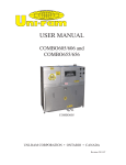
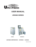
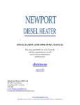
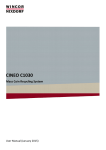
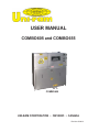
USER MANUAL
COMBO605 and COMBO655
COMBO605
UNI-RAM CORPORATION • ONTARIO • CANADA
Revision 2009-01
MANUAL - COMBO605 and COMBO655
Revision 2009-01
CONTENTS
INTRODUCTION ............................................................................................................ 3
CAUTIONS AND WARNINGS ........................................................................................ 3
FEATURES AND SPECIFICATIONS ............................................................................. 4
SAFETY FEATURES ...................................................................................................... 4
PREPARATION AND SETUP ......................................................................................... 4
SOLVENT REQUIREMENTS (RECYCLER) .................................................................. 4
PAIL SETUP AND CONNECTIONS ............................................................................... 5
OPERATION - SPRAY GUN CLEANING .................................................................... 6-7
OPERATION - SOLVENT RECYCLER ................................................................... ..7-10
THEORY OF OPERATION ........................................................................................... 11
FLOW DIAGRAM ......................................................................................................... 12
TROUBLESHOOTING GUIDE .................................................................................13-14
ERROR CODES. ......................................................................................................15-16
SERVICE PROCEDURES ...................................................................................... 17-18
REPLACEMENT PARTS ............................................................................................... 19
WARRANTY ................................................................................................................. 20
2
MANUAL - COMBO605 and COMBO655
Revision 2009-01
INTRODUCTION
Uni-ram holds many patents on designs used in its innovative products. Every machine is tested for compliance with Quality Assurance standards. Follow the instructions on preparation, use and operation to
operate this machine safely and effectively. Ensure that this manual is readily available to the operator at
all times. If you have any questions about the operation of this machine, contact:
North America:
Uni-ram Technical Service
1-800-417- 9133
Other Continents:
Contact Your Supplier
CAUTIONS AND WARNINGS
•
•
•
•
•
•
•
•
The operator should wear protective clothing in accordance with local safety and environmental
regulations, with a minimum of face goggles and gloves along with an apron and respirator if required.
Always disconnect the power source before performing maintenance.
DO NOT SMOKE OR USE THIS EQUIPMENT NEAR A POTENTIAL SOURCE OF IGNITION SUCH
AS SPARKS OR AN OPEN FLAME. This unit must be located at least 6 feet (1.8 m) from all potential
sources of ignition including electrical receptacles, switches, pilot lights, fixtures and contacts when
installed in a non - hazardous locations.
The ambient temperature must be between 5°C (41°F) to 35°C (95°F).
DO NOT RECYCLE NITROCELLULOSE WHICH IS EXTREMELY VOLATILE. IT AUTOMATICALLY
IGNITES AT 135°C TO 166°C (275°F TO 330°F). Do not install, operate or maintain this equipment
where the auto ignition temperature of the solvent is lower than 250°C (482°F).
Do not install, operate or maintain this equipment where the auto ignition temperature of the hazardous atmosphere(s) is lower than 250°C (482°F).
Solvents that are recycled can be flammable. Establish and follow safe practices to store and handle
solvents.
Units must be installed by a qualified electrician and according to applicable laws.
3
MANUAL - COMBO605 and COMBO655
Revision 2009-01
FEATURES AND SPECIFICATIONS
This unit combines into one cabinet the functions of a Uni-ram UG6000E or UG60000EH Automatic Spray
Gun Cleaner and Uni-ram URS500 (120V) Solvent Recycler. All Uni-ram Solvent Recyclers feature
rapid-start direct electric heating of solvent and a short cool-down time due to high-efficiency condensers and air cooling with a motor driven fan.
SAFETY FEATURES
•
•
•
•
•
•
The Solvent Recycler component is certified under UL standard 2208 and CSA standards C22.2 No.
30 and No. 88 for use in non-hazardous locations as well as for use in hazardous locations Class
1, Division 1, Group D – T2C and Class 1, Division 2, Group D -T2C. The Gun Cleaner component
(UG4000) is FM registered.
Explosion proof construction (Recycler) and intrinsically safe electric circuitry.
Computer controlled (Recycler) with many built-in safety programs including temperature control
of all critical points including tank, condenser and fan motor.
Self Diagnostic (Recycler) error messages are displayed on the Display Panel.
Dual lid cover system (Recycler).
Fume Vent (Gun Cleaner) for disposal of solvent fumes during gun cleaning.
RECYLER SPECIFICATIONS
VOLTAGE(V)
CURRENT USAGE (A)
RECOMMENDED CIRCUIT AMPS
DISTILLATION TANK
DISTILLATION TANK CAPACITY
CONSENSER AND FITTINGS
LID GASKET
UNIT SHIP WEIGHT
UNIT SHIP SIZE (INCL SKIDS)
GUN CLEANER SPECIFICATIONS
110/120
13.3
TANK SIZE
20 X 17 X 14.25”
AUTOMATIC WASH
YES
AUTOMATIC AIR FLUSH
YES
ALUMINUM
AUTOMATIC SOLVENT RINSE
YES
5 US GAL (20L)
AUTOMATIC FUME VENTING
YES
20
COPPER
NEOPRENE
260 / 118 (LB / KG)
40 X 17 X 42”
FUME VENT CONTROL
HOSE CLEANING
YES
COMBO655 ONLY
MANUAL RINSE WITH BRUSH
YES
BRUSH FLOW CONTROL
YES
CHOICE - MANUAL WASH SOLVENT
YES
GUNS CLEANED
2
NO. OF JETS
14
RINSE PUMP (METERING)
100 cc
PREPARATION AND SETUP
•
•
•
•
•
•
•
Carefully inspect the shipping carton for any sign of transport damage.
Carefully remove the unit from the shipping carton.
Check the unit for damage. Report any transport damage immediately to the carrier and your
vendor. Initiate a freight claim with the carrier. The manufacturer is not responsible for freight damage.
A Liner Bag and Retainer Ring are already installed inside the distillation tank.
Check the list of included parts. If any parts are missing, contact your supplier.
Level the unit using the adjustable feet and install the two handles onto the front panel.
Connect the ground wire at the back of the cabinet to an external grounded object.
CAUTION: USE ONLY GENUINE UNI-RAM LINER BAGS WHICH ARE 2 MIL THICK, LIGHT BLUE
IN COLOUR WITH A SAWTOOTH EDGE AND A 3/16” WELD. THEY ARE SPECIALLY MANUFACTURED TO BE STRONG, HEAT RESISTANT AND CHEMICAL RESISTANT. USE OF A NON-UNIRAM LINER BAG MAY VOID THE WARRANTY.
4
MANUAL - COMBO605 and COMBO655
Revision 2009-01
INCLUDED PARTS
MANUAL
LID GASKET
RECYCLER
LINER BAG, 2 SPARES
RECYCLER
SOLVENT OUTLET TUBE
RECYCLER
TRIGGER CLAMP AND PLUG KIT (2)
GUN CLEANER
NOZZLE ADAPTORS (2)
GUN CLEANER
SOLVENT REQUIREMENTS (RECYCLER)
This unit recycles flammable solvents and combustible solvents. Flammable solvents include lacquer thinner, paint thinner, acetone and other paint diluents. Flammable Solvents have a flash point below 38.7°C
(100°F). These solvents are commonly used in the industry as cleaning solvents or paint diluents.
Dirty solvent to be distilled must meet each requirement described below. The Material Safety Data
Sheet (MSDS) provides data on the properties of the virgin solvent.
1) The BP (Boiling Point) of the dirty solvent must be less than 200°C (392°F). BP increases with greater
contamination.
2) The auto-ignition temperature of the solvent to be distilled must be higher than 250°C (482°F) for safe
operation. Do not recycle Nitrocellulose. The auto ignition temperature is 135°C (275°F).
Notes:
•
Recycle recently contaminated solvent only. Standing solvent can become acidic over time.
•
To avoid “FISH EYE” problems, do not recycle both paint dilutents and parts washer solvent in the
same unit.
DEFINITIONS
Flash Point: The lowest temperature at which the vapor of a solvent can be made to ignite momentarily in air.
Auto-ignition temperature (often referred to as “ignition temperature” or “ignition point”): the temperature at which
solvent ignites by itself.
PAIL SETUP AND CONNECTIONS
The unit comes with the pails installed and connected. If the pails need to be reconnected,
use this picture as a guide. For safety, make sure the ground wires are connected.
5
MANUAL - COMBO605 and COMBO655
Revision 2009-01
OPERATION
SPRAY GUN CLEANING
PRE - CLEAN
•
•
Disconnect the spray gun from the air hose. Pour paint from the cup (when present) into a 5 gallon pail
(not supplied).
Rinse cup with solvent and pour into the same 5 gallon pail for later disposal or recycling.
CLEANING SPRAY GUNS AND CUPS
•
•
•
•
•
•
•
Loosen the air cap of the spray gun two full turns.
Lock the trigger in the open position with the Trigger Lock Spring.
Plug air inlet of spray gun with cap to prevent solvent from entering passage. Caps are supplied in the
accessory kit.
Place spray guns facing corner jets. Placement depends on type of spray gun. See pictures below.
Place cups onto the low spray jets and cup holders.
Note re: Gravity Feed Spray Guns: Some customers prefer to clean the cup separate from the spray
gun.
Close the lid and turn the “Auto Wash Timer” knob clockwise to start cleaning. The cleaning cycle
takes about 60 seconds
Push and hold the “Air Rinse” button for about 3 second to air-rinse the guns.
Push and hold the “Clean Rinse” button for about 5 seconds to rinse guns with clean solvent. This will
send a pre-set amount of clean solvent (100 cc) through the jets. Wait 30 seconds for the Rinse Pump
to fully recharge before repeating.
The solvent flow per clean-rinse cycle is limited to 100 cc to minimize consumption. This quantity is
usually sufficient to clean the inside passages of the spray guns.
USING THE MANUAL WASH and MANUAL RINSE FEATURES
•
•
Open the lid and step on the foot left pedal. A dedicated pump delivers wash solvent through the
brush.
Open the lid and step on the right foot pedal. Clean solvent is delivered through the brush.
Solvent flow through the rinse brush is limited to minimize clean solvent consumption.
6
MANUAL - COMBO605 and COMBO655
Revision 2009-01
HOSE CLEANING (COMBO655 ONLY)
•
Models with this feature can be used to clean a paint feeder hose up to 100 feet (30 m) long. Connect
the hose to the two fittings, one on the front and one on the right side. Rotate the “Mode Selector”
handle to the horizontal position and turn the Timer knob clockwise to start the automatic cleaning
cycle.
•
To air-rinse the hose, push and hold the “Air Rinse” button.
•
To rinse the hose with clean solvent, push and hold the
“RINSE CYCLE CONTROL” button for about 5 seconds. This
will use about 100 cc of clean solvent. Wait 30 seconds for the
Rinse Pump to fully recharge before repeating.
•
Disconnect the hose.
FLOW CONTROLS (right side of unit)
Two control levers on the right side of the unit allow the rinse solvent flow and the Brush solvent flow to be adjusted as needed. A
third lever allows the Fume Vent to be turned OFF or ON.
SOLVENT RECYCLNG
Wear protective clothing in accordance with local safety and environmental regulations. Use face goggles
and gloves as a minimum. Use an apron and respirator if required.
The unit is a self-contained gun cleaning / solvent recycling system designed to recycle the solvent used
for cleaning guns. The unit can be used at any time to recycle used solvent either on an ongoing basis
for separate storage or to replace the clean solvent used up during gun cleaning. The gun cleaner can be
used while the recycler is in operation.
Recycling becomes necessary when the WASH PAIL (middle) becomes full or when the LOW LEVEL
INDICATOR gauge indicates that the solvent level in the CLEAN SOLVENT PAIL is too low. At that point,
the guns will no longer be cleaned properly. The level of solvent in the WASH PAIL should be checked
regularly, especially during heavy use as this pail may fill up before the level in the CLEAN RINSE pail
drops to the point where the LOW LEVEL INDICATOR gauge indicates that the level is too low. NOTE:
the gauge only indicates the level correctly when the RINSE CYCLE CONTROL button is pushed.
1) Open the Tank Lid and Safety Cover
•
•
•
Open the safety cover.
Open the inner lid by releasing the Lid Clamp.
Make sure that Tank is empty and that a Liner Bag is properly installed in the Tank.
PULL UP TO OPEN. PUSH DOWN TO LOCK
LID CLAMP
TANK LID
7
MANUAL - COMBO605 and COMBO655
Revision 2009-01
2) Transfer Solvent TO the Recycler Tank
Verify that the solvent to be recycled complies with the requirements described in the section, Solvent
Requirements.
•
•
•
•
Open the Transfer Valve by
turning the handle counterclockwise 90°.
Turn the Transfer Timer knob
clockwise fully. Dirty solvent will
flow from the Transfer Port into
the Liner Bag and stop when
the timer runs out.
Close the Transfer Valve by
turning the handle clockwise
90°.
Close the tank Lid, lock down
the Lid Clamp and close the
Safety Cover.
TRANSFER
TIMER (to
Recycler)
Lid Gasket
Transfer Valve
Transfer Port
3) Change temperature set point, as required. If the Temperature Set
Point is satisfactory, skip this section.
Conditions to consider before starting Setup:
Minimize Temperature Set Point
After recycling there will be a small amount of solvent, about 1/8 US gal (500 ml), remaining in the distillation tank due to condensation. Select the lowest Temperature Set Point that recycles the solvent to this
level.
Estimate Boiling Point
Add 45°C (81°F) to the boiling point of the pure solvent as shown on the MSDS (Material Safety Data
Sheet) or another reliable source.
Recycle more often
The boiling point of the waste solvent mixture increases as it gets dirtier. To reduce the boiling point,
recycle more often.
The display for the Control Panel is located at the top right corner of the base cabinet.
The LEDs for READY(L) and READY(H) on the control panel indicate the Temperature Set Point.
To Change the Temperature Set Point:
Make sure the “HEAT” and “FAN” lights are off. Press and hold the “OFF” button while pressing the “ON”
button repeatedly to cycle through the 6 possible Set Points. If you go past the desired Set Point, continue
to press the “ON” button until you cycle back to the missed Set Point.
TEMPERATURE SET
POINTS
90°C (194°F)
115°C (239°F)
READY LIGHTS
L
*
*
140°C (284°F)
165°C (329°F)
M
*
*
*
190°C (374°F)
200°C (392°F)
*
*
H
*
*
*
The Temperature Set Point is pre-set at the
factory to 200°C (392°F) - all 3 lights are on.
KEYPAD (CONTROL PANEL)
8
MANUAL - COMBO605 and COMBO655
Revision 2009-01
4) Start Recycling
Press “ON” button. Distillation starts, “HEAT” and “FAN” lights come on. If you want to stop recycling
press “OFF”.
5) Finish Recycling
CAUTION: DO NOT OPEN LID UNTIL COOLING IS COMPLETE
The clean recycled solvent is available for use when the heat lamp goes off. Recycling is complete and
the the unit is ready for the next operation when “HEAT” and “FAN” lights are off.
6) Transfer Clean Solvent
a) For models without the Solvent Transfer System: remove the pail and replace with an empty one.
b) For models with the Solvent Transfer System: turn the Transfer Timer knob clockwise fully. The clean
solvent will flow out of the Solvent Receiving Pail into either a free-standing, external container or the
Clean Solvent Pail of a Spray Gun Cleaner. The transfer will stop whwn the timer runs out.
7) Remove Debris:
Remove the Retainer Ring.
Slowly pull the Liner Bag containing the debris out of the distillation tank in a way that the Liner Bag does
not break.
Dispose of the debris in accordance with local regulations.
NOTE: If the bag sticks to the bottom of the tank, turn the recycler on for 5 minutes to loosen the bag from
the bottom of the tank, then lift the bag out while the bag is warm.
8) Clean Distillation Tank and Lid Surface
Distillation Tank:
Wipe and dry tank with a cloth.
Remove any remaining debris from the Distillation Tank using if necessary, plastic or wooden tools. Do
not clean with abrasive or hard metal instruments that can damage the tank. The warranty does not cover
such damage.
Note: There will be about 1/8 Gal (500 ml) of solvent remaining in the Distillation Tank after recycling due
to condensation. This solvent, If left in the tank, can cause corrosion. Dirt and debris left in the tank can
prevent full heat from reaching the dirty solvent during recycling.
Caution: Acidic or chlorinated solvents typically cause corrosion on an aluminum tank. It appears as
black pitting spots on the tank. Excessive pitting leads to an unsafe condition of holes in the walls of the
tank and solvent leakage. Inspect your tank after each batch. If there is excessive pitting, call a Service
Technician and replace the tank with a corrosive resistant, stainless steel one.
Lid Surface:
Use a cloth. Dry and clean the lid and the top of tank where the the Lid Gasket sits to extend the life of the
Lid Gasket and prevent leakage. Avoid rotating the lid during cleaning. The lid gasket is a wear item.
9
MANUAL - COMBO605 and COMBO655
Revision 2009-01
9) Install new Liner Bag
Lift Recycler Safety Cover and Tank Lid fully; lids will stay in the open position.
a) Install the Liner Bag so that the bottom of the Bag sits flat on the bottom of the Distillation Tank as
shown.
b) With thumb and index finger, squeeze the Retainer Ring and insert into inside of the Liner Bag. Let go
and make sure it fits securely in the groove.
d) Fold the flap of the liner bag over the retainer ring.
Caution: Ensure that the bag material does not block the Vapor Outlet.
NOTE: This is a schematic drawing only; not all components are exactly as shown.
10) Inspect Lid Gasket, Remove and Replace if necessary as required
Inspect the Lid Gasket for shrinking, hardness and cuts. The Lid Gasket is a wear item as it is exposed to
high temperature and solvent vapor during distillation. Damage to the lid gasket will cause solvent to leak.
To remove, open the Safety Cover and Tank Lid. Lift out the old gasket by hand and clean the cavity with
a cloth. To Install, place the new gasket in the cavity, rub solvent or soapy water on the gasket to make
insertion easier. Press the gasket firmly into the cavity all around.
Note: Keep a spare in stock. One extra is included with the unit.
11) Transfer Recycled Solvent back to the CLEAN RINSE PAIL.
Turn the knob of the CLEAN TRANSFER TIMER (bottom right) fully.
CLEAN
TRANSFER
TIMER
10
MANUAL - COMBO605 and COMBO655
Revision 2009-01
THEORY OF OPERATION - DISTILLATION PROCESS
Waste solvent consists of the original solvent plus liquid and solid materials picked up during use of the
solvent. Recycling separates the original solvent from the waste materials. During the recycling process,
the distillation tank fills with dirty solvent and the heating element heats the mixture. The solvent mixture
boils and the vapour passes through a cooling condenser where purified, clean solvent, ready for use
condenses out. Waste materials in the dirty solvent boil at a temperature substantially above the Temperature Set Point so they remain in the distillation tank for disposal.
Solvent Recycling
Vapour Outlet tube
(vapor moves
to cooling condenser
from distillation tank)
Distillation
Tank
Condenser
(cools vapor
to a liquid)
Heating Element
Receiving Pail
(contains clean,
recycled solvent)
11
MANUAL - COMBO605 and COMBO655
Revision 2009-01
FLOW DIAGRAM - COMBO605
12
MANUAL - COMBO605 and COMBO655
Revision 2009-01
FLOW DIAGRAM - COMBO655
13
MANUAL - COMBO605 and COMBO655
Revision 2009-01
TROUBLESHOOTING GUIDE
Carry out each action step until a solution is found. If the recommended actions do not solve the problem
call Uni-ram Service in North America or contact a qualified Service Technician.
Caution: Disconnect the power supply before conducting maintenance or service.
PROBLEM
CAUSE
ACTION STEPS
Unit is plugged in, all the lights
on the Panel are Off.
Power is not getting to
the unit.
Reset breaker or replace fuse. If power is
still not getting to the unit, call a Qualified
Service Technician. Ensure that the unit is
the only device on a circuit with sufficient
capacity.
Unit is plugged in, “READY(L)” /
“READY(H)” lights are On, Heat
light fails to come on when “ON”
button is pressed.
Power board or fuse
not functioning.
Call Uni-ram Service
Recycled solvent is not clear
1) The solvent is react- 1) Lower Termperature Set Point following
ing chemically.
Operating Procedure 4.
Dirty solvent remains in Distillation Tank after recycling
2) The solvent flow
path is dirty. One
cause is overfilling the
distillation tank.
2) To clean the path, follow Service Procedure 2 and then recycle 3 gal of clean
solvent.
3) Orange colour due
to rust in receiving
pail.
3) Place a jar under outlet tube and capture
some solvent. If the solvent is clear, replace
the pail with a non-corrosive one.
4) Milky colour due to
presence of water.
4) Eliminate source of water in solvent.
1) Poor heat transfer
due to dirt and debris
left in the tank.
1) Clean the tank, replace the Liner Bag,
recycle with pure solvent to test. If successfull, the problem is due to a dirty tank,
debris left in the tank or the solvent is too
contaminated. Adjust accordingly. Follow
Operating Procedures closely. If the level
of contamination is too high, recycle more
often.
2) Boiling point of
solvent is above Temperature Set Point.
2) Raise the Temperature Set Point and
repeat the recycling operation.The Temperature Set Point should be the BP of pure
solvent (as determined from the MSDS or
other source) plus 45°C (113°F) to allow for
contamination. If the boiing point is above
the maximum Temperature Set Point for
your model (200°C), dirty solvent cannot be
recycled in this unit.
Note: 1/8 Gal (500 ml) of recycled solvent is expected due to
condensation.
Liner Bag sticks
Turn unit on for 5 mininutes and lift out bag
while it is still warm.
14
MANUAL - COMBO605 and COMBO655
Revision 2009-01
PROBLEM
CAUSE
ACTION STEPS
Solvent vapor leaks from the Lid
Gasket
1) Lid Gasket has
excessive wear as
indicated by cracks,
shrinkage, hardness
etc
1) Replace the Lid Gasket (See Operating
Procedure 11).
2) Solvent flow path is
blocked.
2) Follow Service Procedure 2.
3) Lid Tension not
adequate
3) Follow Service Procedure 4.
3) The Lid is not
seated correctly.
3) Follow Service Procedure 5.
4) The temperature
SET-PT too high, resulting in excessively
high solvent vapour
pressure
4) Reduce the Temperature Set Point and
repeat the recycling operation. If successful, continue to recycle using the lower
Temperature Set Point.
1) Use of inferior low
temperature bag.
1) Use new genuine Uni-ram high temperature Liner Bag and recycle.
2) Temperature Set
Point is too high.
2) Reduce the Temperature Set Point and
repeat the recycling operation. If successful, continue to recycle using the lower
Temperature Set Point.
The computer appears to be
operating erratically.
The computer may
require re-booting.
Disconnect the power supply for 30 seconds. Restore power and operate unit.
Residue (puck) in Tank is too
wet.
1) Not enough heat to
vapourize the solvent.
1) Raise the Temperature Set Point
2) Residue cannot be
dried completely due
to its composition.
2) None.
Sections on Bag are brown and
thin due to High Temperature
15
MANUAL - COMBO605 and COMBO655
Revision 2009-01
ERROR CONDITION CODES
The computer constantly monitors the unit as it operates.
AN ERROR CONDITION IS INDICATED BY FLASHING “READY” LIGHTS.
NOTE: On later models of the URS500, due to a change in software, the heater light may flash
during normal operation. For all error conditions except for an error code “22” condition, the Heater light
would be off.
To determine the error type, count the flashes of READY (L ) before READY (H) flashes, then count the
number of flashes for READY (H ). For example, two flashes from READY (L) and then one by READY
(H) indicates error code 21. Look up the Error Code on the Chart below. Press the “OFF” button to stop
the error code and press the “ON” button to resume operation after the error condition has been corrected. If the error persists, call for service.
ERROR
CODE
Flashing LED
Lights
READY
(L)
Description
Action Required
READY
(H)
11
1 TIME
1 TIME
Open circuit - defective tank
thermocouple
12
1 TIME
2 TIMES
Open circuit - defective condens- Contact Uni-Ram Service
er thermocouple
21
2 TIMES
1 TIME
Open Heater Circuit - defective
Contact Uni-Ram Service
component; heater element,
thermostat, wire conductor, blown
fuse. A defective thermostat or
wire terminal is the most likely
cause.
22
2 TIMES
2 TIMES
Defective heater triac; Heater is
still “ON”
23
2 TIMES
3 TIMES
Condenser is overheating or ther- Clean dirty Condenser following
mostat is faulty.
Service Procedure 1. If Thermostat is faulty contact Uni-ram
Service
24
2 TIMES
4 TIMES
If code 23 condition lasts over 10
minutes, this code will show and
operation is terminated.
1) Clean dirty Condenser. See
Service Procedure 1.
2) Position the unit to provide 6
inches (15cm) all around the unit.
3) Check Cooling Fan or Fan Motor.
31
3 TIMES
1 TIME
a) Boiling did not occur within 45
minutes. Tank is either empty or
there is excessive debris in liner
bag or tank is dirty.
a) Clean Distillation Tank following
Operating Procedure 7, replace
liner bag, following Operating Procedure 9.
b) Set-up point is too low.
b) Increase temperature set point
following Operating Procedure 4
and recycle with virgin solvent
c) Boiling point of solvent is
above maximim set point.
c) Solvent cannot be recycled.
16
Contact Uni-Ram Service
Disconnect the power supply
immediately. Contact Uni-Ram
Service
MANUAL - COMBO605 and COMBO655
ERROR
CODE
Flashing LED
Lights
Revision 2009-01
Description
Action Required
Press “OFF” and then “ON” buttons to resume operation. Disconnect power at the source for about
30 seconds. Usually nothing is
wrong with the unit.
READY
(L)
READY
(H)
32
3 TIMES
2 TIMES
Micro Controller has been reset
due to power interruption or drop
in voltage during the recycling
operation.
33
3 TIMES
3 TIMES
a) Recycling did not finish in 6
a) Clean Distillation Tank following
hours due to power interruption or Operating Procedure 7, replace
excessive debris in Liner Bag
Liner Bag, following Operating
Procedure 9,
b) Temperature Set Point is too
low for the solvent.
b) increase Temperature Set Point
following Operating Procedure 4
and recycle with virgin solvent
c) Boiling point of solvent is
above maximim set point.
c) Solvent cannot be recycled.
17
MANUAL - COMBO605 and COMBO655
Revision 2009-01
SERVICE PROCEDURES
1) CLEAN CONDENSER
Using a brush attachment, vacuum the condenser at the back of the unit.
2) CLEAR BLOCKED SOLVENT FLOW PATH
CAUTION: WEAR SAFETY GOGGLES.
A blockage in the solvent flow path (Vapour Outlet - Condenser - Solvent Outlet Tube) can cause solvent
to leak. To determine the location of the blockage, first check the Solvent Outlet Tube and the Vapour
Outlet Fitting for visible signs of blockage or damage. If the problem is not in either of these locations, the
Condenser is problably blocked. To clear the condenser, pour some clean solvent into the Vapour Outlet
and check if it comes out of the Solvent Outlet Tube. If the blockage persists, blow air at about 30 PSI (2
kg/cm2) into the Vapour Outlet. If the air comes out of the Solvent Outlet Tube, the blockage has been
cleared. If not, call for service.
3) REPLACE FUSES
Fuses are located on the Power Control Board inside the Motor Housing.
• Disconnect power supply.
• Remove the Guard Screen by unscrewing two metal screws to get access to the Motor Housing
Power Control Board
Motor Housing
Front Cover
•
•
Unscrew the 6 screws from the Front Cover and pull it gently from the motor housing to expose the
fuses. Note: Care should be taken not to pull the Front Cover too far as some wires may disconnect.
There are two fuses for URS500 series and four fuses for URS600 series.
URS500 series:
Fuses F1: 250 V 20.0 A 314 (Fast type) for Heater
Fuses F2: 250 V 2.0 A 312 (Slow type) for Fan Motor
•
•
•
•
•
•
URS600 Series:
There are two each of F1 and F2 fuses.
Remove the fuses from the board and, using a meter, test each one and replace as needed.
Carefully push the Power Control Board back into the Motor Housing.
Ensure that the wire to the computer board is secure.
Re-install the Front Cover using all 6 screws..
Install the Guard Screen using two metal screws.
Close the Door and re-connect the power supply.
18
MANUAL - COMBO605 and COMBO655
Revision 2009-01
4) INCREASE LID TENSION (BY ADJUSTING SPRING BOLT)
CAUTION:
SHOULD BE DONE ONLY AS A LAST RESORT - FIRST CHECK FOR A WORN LID GASKET, A BLOCKAGE IN THE SOLVENT FLOW PATH , LOOSE HINGE OR CROSS BAR BOLTS OR A SET POINT THAT
IS TOO HIGH FOR THE SOLVENT BEING RECYCLED.
This procedure tightens the Lid by increasing
the tension on the spring attached to the Lid
Bar Spring Bolt Assembly. The Lid and Bolt
Assembly is carefully designed as a Safety
Pressure Relief system to prevent a dangerous build up of pressure inside the closed
tank. Do not adjust the Spring Holding Nut
by more than 2 full turns maximum. If 2
full turns do not solve the problem, call for
service.
Top Nut
Spring Holding Nut
•
•
While holding the top nut with a wrench,
turn the nut below the spring no more than
a 1/2 turn at a time. Turn in a counterclockwise direction (as you look down on
it).
After each 1/2 turn, operate the unit normally and check for leaks.
5) REPOSITION LID and TIGHTEN HINGE AND CROSS BAR BOLTS
The Hinge bolts can loosen over time, causing the lid to shift off center. This can lead to an inadequate
seal and leaking around the Gasket. Loosen the bolts, reposition the lid and re-tighten the bolts.
Hinge
Spring Bolt Assembly
Cross Bar
6) RECOMMENDED 6-MONTH MAINTENANCE
•
•
•
•
Vacuum the condenser (see Service Procedure 1).
Clean the solvent flow path by recycling 3 Gal of clean solvent.
Inspect Distillation Tank for debris, pitting and/or other damage.
Inspect Lid Gasket for wear or damage (see Operating Procedure 11).
19
MANUAL - COMBO605 and COMBO655
Revision 2009-01
REPLACEMENT PARTS
DESCRIPTION
PART NO.
Lid Gasket, Standard (Neoprene)
770-2150N
Liner Bag, Pkg of 10
LB900C-10
Solvent Outlet Tube
770-8131
Trigger Clamp and Plug Kit, Pkg of 2
140-2340
Nozzle Adaptor
110-430
Nozzle Adaptor, Sata
110-430SA
Retainer Ring
770-9110
20
MANUAL - COMBO605 and COMBO655
Revision 2009-01
Full Product Warranty
These Uni-ram products have been engineered and manufactured to high performance standards. Each
unit has been subjected to detailed factory testing before shipment.
This product comes with a one-year full warranty from the date of purchase. Uni-ram Corporation reserves the right to repair or replace the unit, free of charge, to the original purchaser if a part is found to
be defective in material or workmanship as determined by factory service personnel. The items listed
below under “Conditions of Warranty” as consumables are not covered.
Uni-ram reserves the right to direct the customer to ship the unit collect to the Uni-ram factory or to an approved Service Center for repair using the Uni-ram Return Goods Procedure or to repair the unit on-site.
To prevent damage in transport, the purchaser must ship the unit in the original packaging or use alternate adequate packaging. All units must be shipped clean and free of solvent.
Conditions of Warranty:
As Uni-ram Corporation has no control over the working conditions or circumstances under which the
purchaser stores, handles or uses the product, Uni-ram makes no warranty or claim, either expressed or
implied with respect to this product’s fitness for any purpose or the result to be obtained from its use. This
condition applies to the sale of all products and no representative or distributor of Uni-ram Corporation
has the authority to waive or change these conditions.
This warranty applies only to the original purchaser and does not apply if the unit has been misused,
overloaded, neglected, altered or used for any purpose other than those specified in the operating and
installation instructions. Deterioration due to normal wear is not covered by this warranty. Damage due to
accident, transportation, fire, floods or acts of God is also not covered. Units whose serial numbers have
been altered or removed are not covered. The warranty is invalid if unauthorized abrasives are used in
this unit. Unauthorized attempts at self-repair or alterations by the owner also invalidate this warranty.
Interior or exterior finishes are not covered by this warranty.
Consumable Items are not covered by this warranty.
This warranty replaces all other warranties expressed or implied by statute or otherwise.
To make a claim, call Uni-ram Service at 1-800-417-9133 and quote the serial number of the unit.
USE ONLY GENUINE UNI-RAM LINER BAGS WHICH ARE 2 MIL THICK, LIGHT BLUE IN COLOUR
WITH A SAWTOOTH EDGE AND A 3/16” WELD.
THEY ARE SPECIALLY MANUFACTURED TO BE STRONG, HEAT RESISTANT AND CHEMICAL
RESISTANT.
USE OF A NON-UNI-RAM LINER BAG MAY VOID THE WARRANTY.
21