1
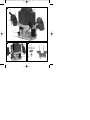
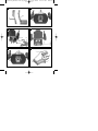
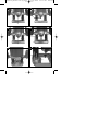
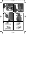
Anleitung BT-RO 1200 E_SPK1:_ Bedienungsanleitung Elektro-Oberfräse t Operating Instructions Electric Router p Mode dʼemploi Défonceuse électrique C Istruzioni per lʼuso Fresatrice verticale elettrica 15.09.2008 15:32 Uhr Seite 1 lL Betjeningsvejledning Elektrisk overfræser A Használati utasítás Villamos -felsőmaró Bf Upute za uporabu Električna glodalica za izradu utora 4 Uputstva za upotrebu Električna glodalica za izradu utora j Návod k obsluze Elektrická horní frézka W Návod na obsluhu Elektrická horná frézka � Art.-Nr.: 43.504.80 I.-Nr.: 01017 BT-RO 1200 E Anleitung BT-RO 1200 E_SPK1:_ 15.09.2008 15:32 Uhr Seite 2 1a 8 6 7 5 7 4 9 10 3 2 1 19 1b 1c 11 22 18 17 20 16 12 3 15 23 13 21 14 2 Anleitung BT-RO 1200 E_SPK1:_ 2 15.09.2008 3 15:32 Uhr Seite 3 1 1B f 1A 2 4 5 3 b 3 21 b a a 2 b a 2 6 20 3 c 13 7 c 20 f b 2 d e 3 Anleitung BT-RO 1200 E_SPK1:_ 8 15.09.2008 15:32 Uhr 9 12 23 10 10 11 12 12 22 10 12 13 15 9 14 4 Seite 4 Anleitung BT-RO 1200 E_SPK1:_ 14 15.09.2008 15:32 Uhr Seite 5 15 18 19 17 16 15 14 16 17 11 5 + — 4 18 19 a c b c 5 Anleitung BT-RO 1200 E_SPK1:_ 15.09.2008 15:33 Uhr Seite 13 GB Important! When using equipment, a few safety precautions must be observed to avoid injuries and damage. Please read the complete operating manual with due care. Keep this manual in a safe place, so that the information is available at all times. If you give the equipment to any other person, give them these operating instructions as well. We accept no liability for damage or accidents which arise due to non-observance of these instructions and the safety information. 1. Safety information Please refer to the booklet included in delivery for the safety instructions. CAUTION! Read all safety regulations and instructions. Any errors made in following the safety regulations and instructions may result in an electric shock, fire and/or serious injury. Keep all safety regulations and instructions in a safe place for future use. 2. Layout (Fig. 1a/1b/1c) 1. Extractor adapter 2. Routing shoe 3. Wing screw 4. ON/OFF switch 5. Safety lock-off 6. Power cable 7. Handle 8. Motor casing 9. Fixing handle 10. Clamp nut 11. Speed control 12. Spindle lock 13. Compass point 14. Revolver end stop 15. End stop 16. Wing screw 17. Pointer 18. Scale 19. Depth stop 20. Guide sleeve 21. Parallel stop 22. Open-ended wrench 23. Clamp 3. Proper use The router is ideal for machining wood and plastic and also for cutting out knots, cutting grooves, removing recesses, copying curves and logos, etc. The router must not be used for machining metal, stone, etc. The machine is to be used only for its prescribed purpose. Any other use is deemed to be a case of misuse. The user / operator and not the manufacturer will be liable for any damage or injuries of any kind caused as a result of this. Please note that our equipment has not been designed for use in commercial, trade or industrial applications. Our warranty will be voided if the machine is used in commercial, trade or industrial businesses or for equivalent purposes. 4. Technical data Mains voltage: 230 V ~ 50 Hz Power input: 1200 W Idling speed: 11,000 – 30,000 rpm Stroke height: 55 mm (cutting depth) Clamp Ø 8 and Ø 6 mm Max. for shaping router: 32 mm II / 쏾 Protection class: Weight: 3.4 kg Sound and vibration Sound and vibration values were measured in accordance with EN 60745. LpA sound pressure level KpA uncertainty 87.3 dB(A) 3 dB LWA sound power level KWA uncertainty 98.3 dB(A) 3 dB Wear ear-muffs. The impact of noise can cause damage to hearing. Total vibration values (vector sum of three directions) determined in accordance with EN 60745. Handles Vibration emission value ah = 4.74 m/s2 K uncertainty = 1,5 m/s2 13 Anleitung BT-RO 1200 E_SPK1:_ 15.09.2008 15:33 Uhr Seite 14 GB Important! The vibration value changes according to the area of application of the electric tool and may exceed the specified value in exceptional circumstances. 5. Before starting the equipment Before you connect the equipment to the mains supply make sure that the data on the rating plate are identical to the mains data. Always pull the power plug before making adjustments to the equipment. All covers and safety devices have to be properly fitted before the machine is switched on. 5.1 Extraction port assembly (Fig. 2-3/Item 1) Important. For health and safety reasons it is imperative that you use a dust extractor. Connect your router to the extraction port (1) of a vacuum cleaner or a dust extraction device. This will provide excellent dust extraction on the workpiece. The benefits are that you will protect both the equipment and your own health. Your work area will also be cleaner and safer. Dust created when working may be dangerous. Refer to the section entitled “Safety instructions”. The vacuum cleaner you use for the extraction work must be suitable for the workpiece material. Use a special vacuum cleaner if you are handling harmful materials. Press the two plastic trays (1A and 1B) together as shown in the figure. Secure the extraction port (1) to the routing shoe (2) using the two countersunk screws (f). The extraction port can be connected to extractor units (vacuum cleaners) with a suction hose. The internal diameter of the suction port is 36 mm. Now fit a suction hose of the appropriate size to the suction port. 5.2 Parallel stop assembly (Fig. 4/Item 21) Push the guide shafts (a) of the parallel stop (21) into the holes (b) on the routing shoe (2). Set the parallel stop (21) to the required dimension and secure it in place with the wing screws (3). 5.3 Fitting the compass point (Fig. 5) You can route circular areas using the compass point (13) and the mounting to go with it. Clamp the compass point (13) to the end of one of the guide rods (a). Push the guide rod (a) into a 14 hole (c) on the routing shoe (2). Secure the guide rod (a) on the routing shoe (2) using the securing screws (8). Set the required radius between the compass point (13) and cutter. Position the compass point (13) in the center of the circle you wish to route. If necessary undo the wing screw (b) on the compass point (13) and extend/shorten the part of the compass point (13) that points downwards. 5.4 Guide sleeve assembly (Fig. 6-7/Item 20) Secure the guide sleeve (20) to the routing shoe (2) using the two countersunk screws (f). The guide sleeve (20) is guided along the template (c) using the guide ring (b). The workpiece (d) must be larger by the difference of “external edge of guide ring” and “external edge of router” (e) to obtain a precise copy. 5.5 Fitting / Removing the cutting tool (Fig. 8-11) Important. Pull out the power plug first. Important. After working with the router, the cutting tool will remain very hot for a relatively long time. Important. Cutters are very sharp. Wear protective gloves at all times when handling cutting tools. Cutters with a shaft diameter of 6 mm and 8 mm may be fitted to this router. Most cutters are available in both sizes. You can used cutters made of the following materials: - HSS – Suitable for machining softwood - TCT – Suitable for machining hardwood, particle board, plastic and aluminum. Select the appropriate cutting tool for the job in hand. When using the cutters for the first time: Remove the plastic packaging from the cutter heads. Clean the nut, clamp and shaft of the cutter before fitting it. Press the spindle lock (12) and allow the spindle to engage by turning it at the same time. Undo the clamp nut (10) using the open-ended spanner (22). If necessary take the cutter you wish to remove out of the clamp (23). Select the appropriate cutting tool for the job in hand. Select the appropriate clamp for the cutter (23). Now fit the clamp (23) and nut (10) into the cutting spindle. Anleitung BT-RO 1200 E_SPK1:_ 15.09.2008 15:33 Uhr Seite 15 GB Guide the cutter shaft into the clamp. Press and hold the spindle lock (12). Tighten the clamp nut (10) using the open-ended spanner (22). The cutter must be inserted at least 20 mm into the clamp (23). Before you start the electric router, check to ensure that the cutting tool is secure and runs smoothly. 5.6 Adjusting the end stops (Fig. 13/Item 15) The height of the end stops (15) can be adjusted as required. To do this, undo the lock nut on the end stop (15) and turn it to the required stop height using a screwdriver. Important. Remove the setting and assembly tools before starting the machine 6. Operation Never use a low quality or damaged cutter. Use only cutting tools with a shaft diameter of 6 mm or 8 mm. The cutters must also be designed for the appropriate idling speed. Secure the workpiece so that it cannot be thrown through the air as you work on it. Use clamps or a vise. Always guide the power cable away from the back of the tool. Never cut over metal parts, screws, nails etc. 6.1 ON/OFF switch (Fig. 16/Item 4) Press the safety lock-off (5) and then press the ON/OFF switch (4) to switch on the machine. Release the ON/OFF switch (4) to switch off the machine. 6.2 Speed control (Fig. 17 – Item 11) The best speed depends on the material and the diameter of the cutter. Select a speed between 11,000 and 30,000 rpm using the speed control switch (11). You can choose from 7 different switch positions. The speeds in the various switch positions are as follows: Switch position 1: approx. 11,000 rpm (minimum speed) Switch position 2: approx. 12,000 rpm Switch position 3: approx. 15,000 rpm Switch position 4: approx. 18,000 rpm Switch position 5: approx. 22,000 rpm Switch position 6: approx. 26,000 rpm Switch position 7: approx. 30,000 rpm (maximum speed) To increase the speed: Move the speed control switch (11) in the plus direction. To reduce the speed: Move the speed control switch (11) in the minus direction. 6.3 Adjusting the routing depth (Fig. 12 – 15) Place the machine on the workpiece. Undo the wing screw (16) and fixing handle (9). Slowly move the machine downwards until the cutter makes contact with the workpiece. Tighten the fixing handle (9). Set the depth stop (19) to the required routing depth using the scale and secure it with the wing screw (16). Test the setting by completing a test cut on a waste piece. 6.4 Routing To avoid damage to the router, make sure there are no foreign objects attached to the workpiece. Connect the mains plug to a suitable socket. Hold the tool using both of its handles (7). Place the router on the workpiece. Set the cutting depth as described in point 6.3. Select the speed as described in point 6.2 and switch the machine on (see point 6.1). Test the machine settings using a piece of waste. Operate the tool at full speed. Only then should you lower the router to its working height and lock the machine with the locking grip (9). Cutting direction: The cutting tool turns clockwise. To avoid accidents you must always cut against the direction in which the tool turns (Fig. 18). Feed speed: It is very important to machine the workpiece at the correct feed speed. We recommend that before you machine the actual workpiece, you carry out several trial cuts on a waste piece of the same type. This will enable you to find the best working speed for the workpiece very easily. Feed speed too low: The cutter could heat up excessively. If you are cutting inflammable material such as wood, the workpiece could ignite. 15 Anleitung BT-RO 1200 E_SPK1:_ 15.09.2008 15:33 Uhr Seite 16 GB Feed speed too high: The cutter could be damaged. Cutting quality: Rough and uneven. Allow the cutter to come to a complete standstill before removing the workpiece or putting down the router. 6.5 Routing in stages Depending on the hardness of the material you wish to cut and the cutting depth, it may be a good idea to proceed in stages. Adjust the end stops as described in point 5.6. If you wish to route in several stages, turn the end stop revolver (14) after you have set the cutting depth as described in point 6.3 so that the depth stop (19) is over the highest end stop (15). Now route in this setting. After completing the first routing operation, adjust the end stop revolver (14) so that the depth stop (19) is above middle end stop (15). Now complete a routing operation in this setting as well. Now set the lowest end stop (15) and finish the routing. 6.6 Routing circles with the compass point (13) Proceed as follows to route circles around a centre point: Fit and adjust the compass point (13) as described in point 5.3. Place the compass point (13) on the centre point of the circle you wish to route and apply pressure to it. Complete the routing operation as described in point 6.4. 6.7 Routing with the parallel stop (21) Proceed as follows to route along a straight outer edge of a workpiece: Fit the parallel stop (21) as described in point 5.2. Guide the parallel stop (21) along the outer edge of the workpiece. Complete the routing operation as described in point 6.4. 6.8 Free-hand routing The router can also be operated without any guide rods. You can use it for freehand routing for creative work such as the production of logos. Use a very flat cutter setting for this purpose. Check the direction in which the cutter is turning as you machine the workpiece (Fig. 18). 16 6.9 Shape and edge cutting (Fig. 19) Special cutters with a guide ring may be used for cutting shapes (a) and edges (b). Fit the cutter. Carefully guide the machine on to the workpiece. Guide the guide journal or ball bearing (c) along the workpiece with gentle pressure. Important: For deep cuts, carry out the work in several steps according to the material in question. Hold the router in two hands when carrying out all cutting work. 7. Replacing the power cable If the power cable for this equipment is damaged, it must be replaced by the manufacturer or its aftersales service or similarly trained personnel to avoid danger. 8. Cleaning, maintenance and ordering of spare parts Always pull out the mains power plug before starting any cleaning work. 8.1 Cleaning Keep all safety devices, air vents and the motor housing free of dirt and dust as far as possible. Wipe the equipment with a clean cloth or blow it with compressed air at low pressure. We recommend that you clean the device immediately each time you have finished using it. Clean the equipment regularly with a moist cloth and some soft soap. Do not use cleaning agents or solvents; these could attack the plastic parts of the equipment. Ensure that no water can seep into the device. 8.2 Carbon brushes In case of excessive sparking, have the carbon brushes checked only by a qualified electrician. Important! The carbon brushes should not be rep laced by anyone but a qualified electrician. 8.3 Maintenance There are no parts inside the equipment which require additional maintenance. Anleitung BT-RO 1200 E_SPK1:_ 15.09.2008 15:33 Uhr Seite 17 GB 8.4 Ordering replacement parts Please quote the following data when ordering replacement parts: Type of machine Article number of the machine Identification number of the machine Replacement part number of the part required For our latest prices and information please go to www.isc-gmbh.info 9. Disposal and recycling The unit is supplied in packaging to prevent its being damaged in transit. This packaging is raw material and can therefore be reused or can be returned to the raw material system. The unit and its accessories are made of various types of material, such as metal and plastic. Defective components must be disposed of as special waste. Ask your dealer or your local council. 17 Anleitung BT-RO 1200 E_SPK1:_ 15.09.2008 Konformitätserklärung k t p m O U q T B Q Z z Seite 66 ISC-GmbH · Eschenstraße 6 · D-94405 Landau/Isar C erklärt folgende Konformität gemäß EU-Richtlinie und Normen für Artikel declares conformity with the EU Directive and standards marked below for the article déclare la conformité suivante selon la directive CE et les normes concernant lʼarticle verklaart de volgende conformiteit in overeenstemming met de EU-richtlijn en normen voor het artikel declara la siguiente conformidad a tenor de la directiva y normas de la UE para el artículo declara a seguinte conformidade de acordo com a directiva CE e normas para o artigo förklarar följande överensstämmelse enl. EUdirektiv och standarder för artikeln ilmoittaa seuraavaa Euroopan unionin direktiivien ja normien mukaista yhdenmukaisuutta tuotteelle erklærer herved følgende samsvar med EUdirektiv og standarder for artikkel заявляет о соответствии товара следующим директивам и нормам EC izjavljuje sljedeću uskladjenost s odredbama i normama EU za artikl. declarå urmåtoarea conformitate cu linia directoare CE μi normele valabile pentru articolul. ürün ile ilgili olarak AB Yönetmelikleri ve Normlar∂ gere©ince aμa©∂daki uygunluk aç∂kla mas∂n∂ sunar. ‰ËÏÒÓÂÈ ÙËÓ ·ÎfiÏÔ˘ıË Û˘Ìʈӛ· Û‡Ìʈӷ Ì ÙËÓ √‰ËÁ›· ∂∂ Î·È Ù· ÚfiÙ˘Ô ÁÈ· ÙÔ ÚÔ˚fiÓ 15:33 Uhr l j A X W e 1 . G 4 H E dichiara la seguente conformità secondo la direttiva UE e le norme per lʼarticolo attesterer følgende overensstemmelse i henhold til EU-direktiv og standarder for produkt prohlašuje následující shodu podle směrnice EU a norem pro výrobek. a következő konformitást jelenti ki a termékekre vonatkozó EU-irányvonalak és normák szerint pojasnjuje sledečo skladnost po smernici EU in normah za artikel. deklaruje zgodność wymienionego poniżej artykułu z następującymi normami na podstawie dyrektywy WE. vydáva nasledujúce prehlásenie o zhode podľa smernice EÚ a noriem pre výrobok. деклаpиpа следното съответствие съгласно диpективите и ноpмите на ЕС за пpодукта. заявляє про відповідність згідно з Директивою ЄС та стандартами, чинними для даного товару deklareerib vastavuse järgnevatele EL direktiivi dele ja normidele deklaruoja atitikti pagal ES direktyvas ir normas straipsniui izjavljuje sledeçi konformitet u skladu s odred bom EZ i normama za artikl Atbilstības sertifikāts apliecina zemāk minēto preču atbilstību ES direktīvām un standartiem Samræmisyfirl‡sing sta›festir eftirfarandi samræmi samkvæmt reglum Evfrópubandalagsins og stö›lum fyrir vörur Oberfräse BT-RO 1200 E X 98/37/EC 87/404/EEC X 2006/95/EC R&TTED 1999/5/EC 97/23/EC 2000/14/EG_2005/88/EC: 2004/108/EC 95/54/EC: 90/396/EEC 97/68/EC: X 89/686/EEC EN 60745-1; EN 60745-2-17; EN 55014-1; EN 55014-2; EN 61000-3-2; EN 61000-3-3 Landau/Isar, den 27.11.2007 Weichselgartner General-Manager Art.-Nr.: 43.504.80 I.-Nr.: 01017 Subject to change without notice 66 Mayr Product-Management Archivierung: 4350480-30-4141800-07 Anleitung BT-RO 1200 E_SPK1:_ 15.09.2008 15:33 Uhr Seite 67 k Nur für EU-Länder Werfen Sie Elektrowerkzeuge nicht in den Hausmüll! Gemäß europäischer Richtlinie 2002/96/EG über Elektro- und Elektronik-Altgeräte und Umsetzung in nationales Recht müssen verbrauchte Elektrowerkzeuge getrennt gesammelt werden und einer umweltgerechten Wiederverwertung zugeführt werden. Recycling-Alternative zur Rücksendeaufforderung: Der Eigentümer des Elektrogerätes ist alternativ anstelle Rücksendung zur Mitwirkung bei der sachgerechten Verwertung im Falle der Eigentumsaufgabe verpflichtet. Das Altgerät kann hierfür auch einer Rücknahmestelle überlassen werden, die eine Beseitigung im Sinne der nationalen Kreislaufwirtschaftsund Abfallgesetze durchführt. Nicht betroffen sind den Altgeräten beigefügte Zubehörteile und Hilfsmittel ohne Elektrobestandteile. t For EU countries only Never place any electric tools in your household refuse. To comply with European Directive 2002/96/EC concerning old electric and electronic equipment and its implementation in national laws, old electric tools have to be separated from other waste and disposed of in an environment-friendly fashion, e.g. by taking to a recycling depot. Recycling alternative to the demand to return electrical devices: As an alternative to returning the electrical device, the owner is obliged to cooperate in ensuring that the device is properly recycled if ownership is relinquished. This can also be done by handing over the used device to a returns center, which will dispose of it in accordance with national commercial and industrial waste management legislation. This does not apply to the accessories and auxiliary equipment without any electrical components which are included with the used device. p Uniquement pour les pays de l'Union Européenne Ne jetez pas les outils électriques dans les ordures ménagères. Selon la norme européenne 2002/96/CE relative aux appareils électriques et systèmes électroniques usés et selon son application dans le droit national, les outils électriques usés doivent être récoltés à part et apportés à un recyclage respectueux de l'environnement. Possibilité de recyclage en alternative à la demande de renvoi : Le propriétaire de lʼappareil électrique est obligé, en guise dʼalternative à un envoi en retour, à contribuer à un recyclage effectué dans les règles de lʼart en cas de cessation de la propriété. Lʼancien appareil peut être remis à un point de collecte dans ce but. Cet organisme devra lʼéliminer dans le sens de la Loi sur le cycle des matières et les déchets. Ne sont pas concernés les accessoires et ressources fournies sans composants électroniques. 67 Anleitung BT-RO 1200 E_SPK1:_ 15.09.2008 15:33 Uhr Seite 74 t GUARANTEE CERTIFICATE Dear Customer, All of our products undergo strict quality checks to ensure that they reach you in perfect condition. In the unlikely event that your device develops a fault, please contact our service department at the address shown on this guarantee card. Of course, if you would prefer to call us then we are also happy to offer our assistance under the service number printed below. Please note the following terms under which guarantee claims can be made: 1. These guarantee terms cover additional guarantee rights and do not affect your statutory warranty rights. We do not charge you for this guarantee. 2. Our guarantee only covers problems caused by material or manufacturing defects, and it is restricted to the rectification of these defects or replacement of the device. Please note that our devices have not been designed for use in commercial, trade or industrial applications. Consequently, the guarantee is invalidated if the equipment is used in commercial, trade or industrial applications or for other equivalent activities. The following are also excluded from our guarantee: compensation for transport damage, damage caused by failure to comply with the installation/assembly instructions or damage caused by unprofessional installation, failure to comply with the operating instructions (e.g. connection to the wrong mains voltage or current type), misuse or inappropriate use (such as overloading of the device or use of non-approved tools or accessories), failure to comply with the maintenance and safety regulations, ingress of foreign bodies into the device (e.g. sand, stones or dust), effects of force or external influences (e.g. damage caused by the device being dropped) and normal wear resulting from proper operation of the device. The guarantee is rendered null and void if any attempt is made to tamper with the device. 3. The guarantee is valid for a period of 2 years starting from the purchase date of the device. Guarantee claims should be submitted before the end of the guarantee period within two weeks of the defect being noticed. No guarantee claims will be accepted after the end of the guarantee period. The original guarantee period remains applicable to the device even if repairs are carried out or parts are replaced. In such cases, the work performed or parts fitted will not result in an extension of the guarantee period, and no new guarantee will become active for the work performed or parts fitted. This also applies when an on-site service is used. 4. In order to assert your guarantee claim, please send your defective device postage-free to the address shown below. Please enclose either the original or a copy of your sales receipt or another dated proof of purchase. Please keep your sales receipt in a safe place, as it is your proof of purchase. It would help us if you could describe the nature of the problem in as much detail as possible. If the defect is covered by our guarantee then your device will either be repaired immediately and returned to you, or we will send you a new device. Of course, we are also happy offer a chargeable repair service for any defects which are not covered by the scope of this guarantee or for units which are no longer covered. To take advantage of this service, please send the device to our service address. 74