1
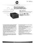
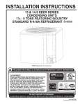
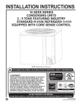
INSTALLATION INSTRUCTIONS
AIR-COOLED CONDENSING UNITS
EQUIPPED WITH THE COMFORT CONTROL SYSTEM™
(-)ANL-JEZ MODEL SERIES - 13 SEER
(-)APL-JEZ MODEL SERIES - 14 SEER
(-)APM-JEZ MODEL SERIES - 14.5 SEER
FEATURING EARTH-FRIENDLY
R-410A REFRIGERANT
refrigerant
!
RECOGNIZE THIS SYMBOL AS AN INDICATION OF IMPORTANT SAFETY INFORMATION!
!
WARNING
THESE INSTRUCTIONS ARE INENDED AS AN AID TO
QUALIFIED, LICENSED SERVICE PERSONNEL FOR PROPER
INSTALLATION, ADJUSTMENT AND OPERATION OF THIS
UNIT. READ THESE INSTRUCTIONS THOROUGHLY BEFORE
ATTEMPTING INSTALLATION OR OPERATION. FAILURE TO
FOLLOW THESE INSTRUCTIONS MAY RESULT IN IMPROPER
INSTALLATION, ADJUSTMENT, SERVICE OR MAINTENANCE
POSSIBLY RESULTING IN FIRE, ELECTRICAL SHOCK,
PROPERTY DAMAGE, PERSONAL INJURY OR DEATH.
(14.5 SEER MODELS
& 14 OR 13 SEER
MODELS IN CERTAIN
MARKED SYSTEMS)
ISO 9001:2000
DO NOT DESTROY THIS MANUAL
PLEASE READ CAREFULLY AND KEEP IN A SAFE PLACE FOR FUTURE REFERENCE BY A SERVICEMAN
[ ] INDICATES METRIC CONVERSIONS
92-21354-55-06
SUPERSEDES 92-21354-55-05
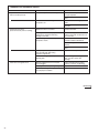
TABLE OF CONTENTS
Checking Product Received . . . . . . . . . . . . . . . . . . . . . . . . . . . . . . . . . . . . . .2
Dimensions . . . . . . . . . . . . . . . . . . . . . . . . . . . . . . . . . . . . . . . . . . . . . . . . . .3
Electrical & Physical Data . . . . . . . . . . . . . . . . . . . . . . . . . . . . . . . . . . . . . . .4
General . . . . . . . . . . . . . . . . . . . . . . . . . . . . . . . . . . . . . . . . . . . . . . . . . . . . .5
Application . . . . . . . . . . . . . . . . . . . . . . . . . . . . . . . . . . . . . . . . . . . . . . . . . . .5
Locating Unit . . . . . . . . . . . . . . . . . . . . . . . . . . . . . . . . . . . . . . . . . . . . . . . . .5
Unit Mounting . . . . . . . . . . . . . . . . . . . . . . . . . . . . . . . . . . . . . . . . . . . . . . . . .7
Factory-Preferred Tie-Down Method . . . . . . . . . . . . . . . . . . . . . . . . . . . . . . .7
Refrigerant Connections . . . . . . . . . . . . . . . . . . . . . . . . . . . . . . . . . . . . . . . .8
Tools Required for Installing & Servicing R-410A Models . . . . . . . . . . . . . . .8
Specification of R-410A . . . . . . . . . . . . . . . . . . . . . . . . . . . . . . . . . . . . . . . . .8
Quick Reference Guide For R-410A . . . . . . . . . . . . . . . . . . . . . . . . . . . . . . .8
Replacement Units . . . . . . . . . . . . . . . . . . . . . . . . . . . . . . . . . . . . . . . . . . . . .9
Evaporator Coil . . . . . . . . . . . . . . . . . . . . . . . . . . . . . . . . . . . . . . . . . . . . . . .9
Interconnecting Tubing . . . . . . . . . . . . . . . . . . . . . . . . . . . . . . . . . . . . . . .9-11
Evacuation Procedure . . . . . . . . . . . . . . . . . . . . . . . . . . . . . . . . . . . . . . . . .11
Start-Up and Performance . . . . . . . . . . . . . . . . . . . . . . . . . . . . . . . . . . . . . .13
Checking Airflow . . . . . . . . . . . . . . . . . . . . . . . . . . . . . . . . . . . . . . . . . . . . .13
Checking Refrigerant Charge . . . . . . . . . . . . . . . . . . . . . . . . . . . . . . . . . . .13
Charging by Liquid Pressure . . . . . . . . . . . . . . . . . . . . . . . . . . . . . . . . . . . .14
Charging by Units with R-410A Refrigerant . . . . . . . . . . . . . . . . . . . . . . . . .14
Charging by Weight . . . . . . . . . . . . . . . . . . . . . . . . . . . . . . . . . . . . . . . . . . .15
Final Leak Testing . . . . . . . . . . . . . . . . . . . . . . . . . . . . . . . . . . . . . . . . . . . .15
Electrical Wiring . . . . . . . . . . . . . . . . . . . . . . . . . . . . . . . . . . . . . . . . . . . . . .16
Hard Start Components . . . . . . . . . . . . . . . . . . . . . . . . . . . . . . . . . . . . . . . .17
High and Low Pressure Controls (HPC or LPC) . . . . . . . . . . . . . . . . . . . . .17
Field Installed Accessories . . . . . . . . . . . . . . . . . . . . . . . . . . . . . . . . . . . . .17
Comfort Control System . . . . . . . . . . . . . . . . . . . . . . . . . . . . . . . . . . . . . . . .18
Control Description . . . . . . . . . . . . . . . . . . . . . . . . . . . . . . . . . . . . . . . . . . .18
ICC Control Operation . . . . . . . . . . . . . . . . . . . . . . . . . . . . . . . . . . . . . . . . .19
Active Compressor Protection Mode . . . . . . . . . . . . . . . . . . . . . . . . . . . . . .20
Test and Fault Recall Modes . . . . . . . . . . . . . . . . . . . . . . . . . . . . . . . . . . . .21
Status and Diagnostic Description . . . . . . . . . . . . . . . . . . . . . . . . . . . . .22-23
Service . . . . . . . . . . . . . . . . . . . . . . . . . . . . . . . . . . . . . . . . . . . . . . . . . . . . .23
Troubleshooting . . . . . . . . . . . . . . . . . . . . . . . . . . . . . . . . . . . . . . . . . . .24-27
Service Analyzer Charts . . . . . . . . . . . . . . . . . . . . . . . . . . . . . . . . . . . . .28-32
ANL-JEZ-Diagnostic Label . . . . . . . . . . . . . . . . . . . . . . . . . . . . . . . . . . .33-34
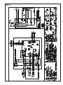
Wiring Diagram . . . . . . . . . . . . . . . . . . . . . . . . . . . . . . . . . . . . . . . . . . . . . .35
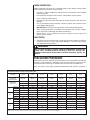
CHECKING PRODUCT RECEIVED
Upon receiving unit, inspect it for any shipping damage. Claims for damage, either
apparent or concealed, should be filed immediately with the shipping company.
Check condensing unit model number, electrical characteristics and accessories to
determine if they are correct and match the original order from the local distributor.
Check system components (evaporator coil, condensing unit, evaporator blower,
etc.) to make sure they are properly matched.
2
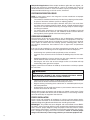
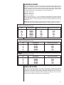
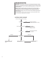
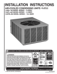
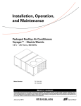
UNIT MODEL NUMBER EXPLANATION
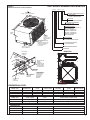
FIGURE 1
DIMENSIONS AND INSTALLATION CLEARANCES
(-) A N L
– 018 J E Z
DISCHARGE
AIR AIR
DISCHARGE
ALLOW 600 [1524 mm] CLEARANCE
[1524 mm] CLEARANCE
ALLOW 60”
COOLING CONNECTION FITTING
Z - SWEAT WITH
Z - SCROLL COMPRESSOR
W
W
VARIATION
E = ELECTRONIC VARIATION
L
ELECTRICAL DESIGNATION
J = 208/230V-1-60
HH
COOLING CAPACITY
-018 = 18,000 BTUH (-)APL ONLY)
-024 = 24,000 BTUH
-030/-031 = 30,000 BTUH
-036/-037 = 36,000 BTUH
-042/-043 = 42,000 BTUH
-048/-049 = 48,000 BTUH
-060 = 60,000 BTUH
ACCESS
ACCESS
PANEL
PANEL
AIR INLETS
INLETS
AIR
(LOUVERS)
(LOUVERS)
ALLOW 120 [305 mm]
MIN. CLEARANCE
6" (305 mm)
ALLOW
3 SIDES
MIN CLEARANCE
3 SIDES
DESIGN SERIES
L = R-410A
M = R-410A SECOND DESIGN
ALTERNATE
HIGH VOLTAGE
LINE
VOLTAGE
CONNECTION*
CONNECTION (KNOCKOUT)
1 / [34 mm]
(KNOCKOUT)
CONNECT THE LINE VOLTAGE
CONDUIT TO THE BOTTOM
OF THE CONTROL BOX
111⁄32" (34 mm)
11 320
ALLOW 240 [610 mm]
24” [610 mm]
ALLOW
ACCESS CLEARANCE
ACCESS CLEARANCE
N = STANDARD EFFICIENCY
P = HIGH EFFICIENCY
REMOTE CONDENSING UNIT
TRADENAME
BASE PAN
LOW
VOLTAGE
LOWVOLTAGE
CONNECTION
CONNECTION
7/8"7⁄8[22
” [22mm]
mm]
A-00002
SERVICE
SERVICE
FITTINGS
FITTINGS
LINE VOLTAGE CONNECTION*
(KNOCKOUT)
HIGH
VOLTAGE
CONNECT THE LINE
CONNECTION
VOLTAGE CONDUIT
11/32" [34 mm]
1TO
THE BOTTOM OF
THE CONTROL BOX
3
000
A-0
LIQUID LINE
LIQUID
LINE
CONNECTION
CONNECTION
SERVICE ACCESS
SERVICE
ACCESS
TO ELECTRICAL &
TO
ELECTRICAL
&
VALVES
ALLOW
2277⁄8/”8"[73
mm]
DIA.
[73 mm] DIA.
VALVES
ALLOW
24” [610mm]
ACCESSORY
ACCESSORY
24"
[610 mm]
CLEARANCE
KNOCKOUTS
KNOCKOUTS
ONE SIDE
CLEARANCE
VAPORLINE
LINE
VAPOR
CONNECTION
CONNECTION
HIGH PRESSURE
CONTROL
(AUTO-RESET)
BOTTOM VIEW SHOWING DRAIN OPENINGS
(\\\\\ SHADED AREAS).
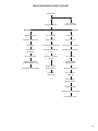
DIMENSIONAL DATA
CONDENSING UNIT
MODEL (-)ANL
024JEZ/031JEZ
030JEZ
036JEZ / 042JEZ
043/037JEZ
049JEZ
HEIGHT “H” (INCHES)
19”
19”
25”
23”
29”
33”
LENGTH “L” (INCHES)
401⁄2”
443⁄8”
443⁄8”
443⁄8”
443⁄8”
443⁄8”
WIDTH “W” (INCHES)
275⁄8”
311⁄2”
311⁄2”
311⁄2”
311⁄2”
311⁄2”
CONDENSING UNIT
MODEL (-)APL
018JEZ / 024JEZ
030JEZ
048JEZ / 060JEZ
036JEZ / 042JEZ / 048JEZ / 060JEZ
HEIGHT “H” (INCHES)
19”
29”
33”
LENGTH “L” (INCHES)
401⁄2”
443⁄8”
443⁄8”
WIDTH “W” (INCHES)
275⁄8”
311⁄2”
311⁄2”
024JEZ/030JEZ
036JEZ / 042JEZ / 048JEZ / 060JEZ
CONDENSING UNIT
MODEL (-)APM
018JEZ
HEIGHT “H” (INCHES)
19”
29”
33”
LENGTH “L” (INCHES)
401⁄2”
443⁄8”
443⁄8”
WIDTH “W” (INCHES)
275⁄8”
311⁄2”
311⁄2”
3
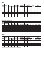
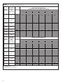
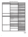
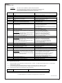
TABLE 1
(-)ANL ELECTRICAL AND PHYSICAL DATA
ELECTRICAL
PHYSICAL
Compressor
Fuse
or
HACR
Model
Fan Motor Minimum
Outdoor Coil
Phase
Circuit Breaker
Number
R-410A
Rated Load Locked Rotor Full Load Circuit
Frequency
(Hz)
(-)ANLOz. [g]
Amperes Ampacity Minimum Maximum Face Area No.
Amperes
CFM
Voltage (Volts) Amperes
(FLA) Amperes Amperes Amperes Sq. Ft. [m2] Rows
{RAL)
(LRA)
[L/s]
Net
Lbs. [kg]
Shipping
Lbs. [kg]
024JEZ
030JEZ
031JEZ
036JEZ
037JEZ
042JEZ
043JEZ
048JEZ
049JEZ
060JEZ
140 [63.5]
160 [72.6]
142 [65]
205 [93]
160 [72]
205 [93]
205 [93]
230 [104.3]
235 [106]
250 [113.4]
150 [68]
170 [77.1]
152 [70]
215 [97.5]
170 [77]
215 [97.5]
215 [97]
240 [108.9]
245 [111]
260 [117.9]
1-60-208-230
1-60-208-230
1-60-208-230
1-60-208-230
1-60-208-230
1-60-208-230
1-60-208-230
1-60-208-230
1-60-208-230
1-60-208-230
12.8/12.8
14.1/14.1
14.1/14.1
17.9/17.9
17.9/17.9
17.9/17.9
17.9/17.9
21.8/21.8
21.8/21.8
26.3/26.3
58.3
73
73
112
112
112
109
117
117
134
0.6
0.8
0.6
0.8
1.2
1.2
1.2
1.2
1.2
1.2
17/17
19/19
19/19
24/24
24/24
24/24
27/27
29/29
29/29
35/35
20/20
25/25
25/25
30/30
30/30
30/30
35/35
35/35
35/35
45/45
25/25
30/30
30/30
40/40
40/40
40/40
45/45
50/50
50/50
60/60
11 [1.02]
12.94 [1.2]
11 [1.02]
17.26 [1.6]
16.1 [1.5]
17.26 [1.6]
17.26 [1.6]
23.01 [2.14]
20.1 [1.8]
23.01 [2.14]
1
1
1
1
1
1
1
1
1
1
1920 [906]
2470 [1166]
1920 [906]
2570 [1213]
2300 [1085]
3290 [1553]
3200 [1510]
3500 [1652]
3200 [1510]
3500 [1652]
72 [2041]
94 [2665]
83 [2353]
113 [3204]
106 [3005]
130 [3686]
115 [3260]
145 [4111]
132 [3742]
180 [5103]
Weight
NOTE: Factory refrigerant charge includes refrigerant for 15 feet of standard line set.
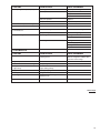
TABLE 2
(-)APL ELECTRICAL AND PHYSICAL DATA
PHYSICAL
ELECTRICAL
Compressor
Fuse
or
HACR
Model
Fan Motor Minimum
Refrig.
Outdoor Coil
Phase
Circuit Breaker
Number
Per
Rated Load Locked Rotor Full Load Circuit
Frequency
(Hz)
RAPLAmperes Ampacity Minimum Maximum Face Area No.
Circuit
Amperes
CFM
Voltage (Volts) Amperes
(FLA) Amperes Amperes Amperes Sq. Ft. [m2] Rows
Oz. [g]
{RLA)
(LRA)
[L/s]
018J*Z
024J*Z
030J*Z
036J*Z
042J*Z
048J*Z
060J*Z
1-60-208/230
1-60-208-230
1-60-208-230
1-60-208-230
1-60-208-230
1-60-208-230
1-60-208-230
9/9
13.5/13.5
12.8/12.8
16.7/16.7
17.9/17.9
21.8/21.8
26.4/26.4
48
58.3
64
79
112
117
134
0.8
0.8
1.2
1.2
1.2
1.2
1.2
13/13
18/18
18/18
23/23
24/24
29/29
35/35
15/15
25/25
25/25
30/30
30/30
35/35
45/45
20/20
30/30
30/30
35/35
40/40
50/50
60/60
11 [1.02]
11 [1.02]
20 [1.86]
23.01 [2.14]
23.01 [2.14]
23.01 [2.14]
44 [4.09]
1
1
1
1
1
1
2
1900 [897]
2300 [1085]
3200 [1510]
3200 [1510]
3200 [1510]
3300 [1557]
3100 [1463]
79 [2240]
105 [2977]
135 [3827]
141 [3997]
152 [4309]
152 [4309]
286 [8108]
Weight
Net
Lbs. [kg]
Shipping
Lbs. [kg]
140 [63.5] 155 [70.3]
140 [63.5] 187 [84.8]
200 [90.7] 213 [96.6]
230 [104.3] 228 [103.4]
230 [104.3] 252 [114.3]
230 [104.3] 253 [114.8]
280 [127] 305 [138.3]
NOTE: Factory refrigerant charge includes refrigerant for 15 feet of standard line set.
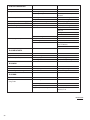
TABLE 3
(-)APM ELECTRICAL AND PHYSICAL DATA
ELECTRICAL
PHYSICAL
Compressor
Fuse or HACR
Model
Refrig.
Fan Motor Minimum
Outdoor Coil
Phase
Circuit Breaker
Number
Per
Rated Load Locked Rotor Full Load Circuit
Frequency
(Hz)
RAPMCircuit
Amperes Ampacity Minimum Maximum Face Area No.
Amperes
Amperes
CFM
Voltage (Volts)
Oz. [g]
(FLA) Amperes Amperes Amperes Sq. Ft. [m2] Rows
{RLA)
(LRA)
[L/s]
Rev. 1/13/2009
018JEZ 1-60-208/230
024JEZ 1-60-208-230
030JEZ 1-60-208-230
036JEZ 1-60-208-230
042JEZ 1-60-208-230
048JEZ 1-60-208-230
060JEZ 1-60-208-230
9/9
13.5/13.5
12.8/12.8
16/16
17.9/17.9
21.8/21.8
26.4/26.4
48
58.3
64
79
112
117
134
0.8
1.1
0.8
0.8
2.8
2.8
2.8
13/13
18/18
17/17
21/21
26/26
31/31
36/36
15/15
25/25
25/25
25/25
30/30
40/40
45/45
NOTE: Factory refrigerant charge includes refrigerant for 15 feet of standard line set.
4
20/20
30/30
25/25
35/35
40/40
50/50
60/60
11 [1.02]
20 [1.86]
20 [1.86]
23.01 [2.14]
23.01 [2.14]
23.01 [2.14]
23 [2.14]
1
1
1
1
1
2
2
2300 [1085]
3300 [1557]
3300 [1557]
3300 [1557]
3300 [1557]
3300 [1557]
3300 [1557]
82 [2325]
128 [3629]
129 [3657]
146 [4139]
152 [4309]
203 [5755]
262 [7428]
Weight
Net
Lbs. [kg]
Shipping
Lbs. [kg]
137 [62.1] 152 [68.9]
190 [86.2] 205 [93]
200 [90.7] 213 [96.6]
201 [91.2] 223 [101.2]
224 [101.6] 246 [111.6]
265 [120.2] 290 [131.5]
274 [124.3] 299 [135.6]
! WARNING
THE MANUFACTURER’S WARRANTY DOES NOT COVER ANY
DAMAGE OR DEFECT TO THE
AIR CONDITIONER CAUSED BY
THE ATTACHMENT OR USE OF
ANY COMPONENTS. ACCESSORIES OR DEVICES (OTHER
THAN THOSE AUTHORIZED BY
THE MANUFACTURER) INTO,
ONTO OR IN CONJUNCTION
WITH THE AIR CONDITIONER.
YOU SHOULD BE AWARE THAT
THE USE OF UNAUTHORIZED
COMPONENTS, ACCESSORIES
OR DEVICES MAY ADVERSELY
AFFECT
THE
OPERATION
OF THE AIR CONDITIONER AND
MAY ALSO ENDANGER LIFE
AND PROPERTY. THE MANUFACTURER
DISCLAIMS
ANY
RESPONSIBILITY FOR SUCH
LOSS OR INJURY RESULTING
FROM THE USE OF SUCH
UNAUTHORIZED COMPONENTS,
ACCESSORIES OR DEVICES.
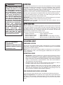
GENERAL
The information contained in this manual has been prepared to assist in the proper
installation, operation and maintenance of the air conditioning system. Improper
installation, or installation not made in accordance with these instructions, can
result in unsatisfactory operation, noise or component failures, and/or dangerous
conditions, and can cause the related warranty not to apply.
Read this manual and any instructions packaged with separate equipment required
to make up the system prior to installation. Retain this manual for future reference.
To achieve optimum efficiency and capacity, the indoor cooling coils listed in the
condensing unit specification sheet should be used.
IMPORTANT: We recommend replacement of any HVAC equipment that has been
subjected to flooding in order to avoid any risk of injury or harm.
IMPORTANT: Use all available safety precautions during the installation and servicing of any HVAC equipment.
APPLICATION
Before installing any air conditioning equipment, a duct analysis of the structure and
a heat gain calculation must be made. A heat gain calculation begins by measuring
all external surfaces and openings that gain heat from the surrounding air and
quantifying that heat gain. A heat gain calculation also calculates the extra heat
load caused by sunlight and by humidity removal.
There are several factors that the installers must consider:
•
•
•
•
Outdoor unit location
System refrigerant charge
Indoor unit blower speed
System air balancing
•
•
•
•
Proper equipment evacuation
Indoor unit airflow
Supply and return air duct design and sizing
Diffuser and return air grille location and sizing
MATCH ALL COMPONENTS:
LOCATING UNIT
• OUTDOOR UNIT
CONDENSER LOCATION
• INDOOR COIL/METERING DEVICE
Consult local and national building codes and ordinances for special installation
requirements. Following location information will provide longer life and simplified
servicing of the outdoor condenser.
• INDOOR AIR HANDLER/FURNACE
• REFRIGERANT LINES
NOTE: These units must be installed outdoors. No ductwork can be attached, or
other modifications made, to the discharge grille. Modifications will affect performance or operation.
OPERATIONAL ISSUES
•
IMPORTANT: Locate the condenser in a manner that will not prevent, impair or
compromise the performance of other equipment horizontally installed in proximity to the unit. Maintain all required minimum distances to gas and electric
meters, dryer vents, any exhaust and inlet openings. In the absence of National
Codes, or manaufacturers’ recommendations, local code recommendations
and requirements will take presidence.
•
Refrigerant piping and wiring should be properly sized and kept as short as
possible to avoid capacity losses and increased operating costs.
•
Locate the condenser where water run off will not create a problem with the
equipment. Position the unit away from the drip edge of the roof whenever possible. Units are weatherized, but can be affected by water pouring into the unit
from the junction of rooflines without protective guttering.
FOR CONDENSERS WITH SPACE LIMITATIONS
In the event that a space limitation exists, we will permit the following clearances:
Single Unit Applications: One condenser inlet air grille side may be reduced to no
less than a 6-inch clearance. Clearances below 6 inches will reduce unit capacity
and efficiency. Do not reduce the 60-inch discharge, or the 24-inch service clearances.
5
Multiple Unit Applications: When multiple condenser grille sides are aligned, a 6inch per unit clearance is recommended, for a total of 12” between two units. Two
combined clearances below 12 inches will reduce capacity and efficiency. Do not
reduce the 60-inch discharge, or 24-inch service, clearances.
CUSTOMER SATISFACTION ISSUES
NOTE: In some cases, noise in the living area has been traced back to improper
installation of equipment.
•
•
•
The condenser should be located away from the living, sleeping and recreational spaces of the owner and those spaces on adjoining property.
Avoid direct contact with water pipes, ductwork, floor joists, wall studs, floors
and walls when installing refrigerant tubing. Do not suspend refrigerant tubing
from joists or wall studs. When necessary, use hanger straps to secure refrigerant tubing to insulation.
To prevent noise transmission, the mounting pad for the outdoor unit should
not be connected to the structure, and should be located sufficient distance
above grade to prevent ground water from entering the unit.
CORROSIVE ENVIRONMENT
The metal parts of this unit may be subject to rust or deterioration if exposed to a
corrosive environment. This oxidation could shorten the equipment’s useful life.
Corrosive elements include, but are not limited to, salt spray, fog or mist in seacoast
areas, sulphur or chlorine from lawn watering systems, swimming pools, and various chemical contaminants from industries such as paper mills and petroleum
refineries.
If the unit is to be installed in an area where contaminants are likely to be a problem, special attention should be given to the equipment location and exposure.
•
Avoid having lawn sprinkler heads spray directly on the unit cabinet.
•
In coastal areas, locate the unit on the side of the building away from the waterfront.
•
Shielding provided by a fence or shrubs may give some protection, but cannot
violate minimum airflow and service access clearances.
•
Elevating the unit off its slab or base enough to allow air circulation will help
avoid holding water against the basepan.
Regular maintenance will reduce the build-up of contaminants and help to protect
the unit’s finish.
! WARNING
DISCONNECT ALL POWER TO UNIT BEFORE STARTING
MAINTENANCE. FAILURE TO DO SO CAN CAUSE ELECTRICAL SHOCK
RESULTING IN SEVERE PERSONAL INJURY OR DEATH.
•
Frequent washing of the cabinet, fan blade and coil with fresh water will remove
most of the salt or other contaminants that build up on the unit.
•
Regular cleaning and waxing of the cabinet with an automobile polish will provide some protection.
•
A liquid cleaner may be used several times a year to remove matter on the cabinet that will not wash off with water.
Several different types of protective coil-coatings are offered in some areas. These
coatings may provide some benefit, but the effectiveness of such coating materials
cannot be verified by the equipment manufacturer.
PROPER INSTALLATION
Proper sizing and installation of equipment is critical to achieve optimal performance. Use the information in this Installation Instruction Manual and reference the
applicable Engineering Specification Sheet when installing this product.
IMPORTANT: This product has been designed and manufactured to meet ENERGY STAR® criteria for energy efficiency when matched with appropriate coil components. However, proper refrigerant charge and proper air flow are critical to achieve
rated capacity and efficiency. Installation of this product should follow the manufacturer’s refrigerant charging and air flow instructions. Failure to confirm proper
charge and airflow may reduce energy efficiency and shorten equipment life.
6
UNIT MOUNTING
If elevating the condensing unit, either on a flat roof or on a slab, observe the
following guidelines.
•
•
The base pan provided elevates the condenser coil 3/4” above the base pad.
If elevating a unit on a flat roof, use 4” x 4” (or equivalent) stringers positioned
to distribute unit weight evenly and prevent noise and vibration.
NOTE: Do not block drain openings shown in Figure 1.
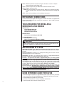
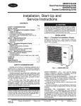
FACTORY-PREFERRED TIE-DOWN METHOD
FOR CONDENSING UNITS
IMPORTANT: These instructions are intended as a guide to securing equipment for
wind-load ratings of “120 MPH sustained wind load” and “3-second, 150 MPH gust.”
While this procedure is not mandatory, the Manufacturer does recommend that
equipment be properly secured in areas where high wind damage may occur.
STEP 1: Before installing, clear pad of any dirt or debris.
IMPORTANT: The pad must be constructed of industry-approved materials,
and must be thick enough to accommodate the concrete fastener.
STEP 2: Center base pan on pad, ensuring it is level.
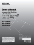
STEP 3: Using basepad as a guide, mark spots on concrete where 4 holes will be
drilled (see Figure 2).
TABLE 4
DIMENSIONS OF BASE PAN
MODEL NUMBER
ANL-024JEZ/030JEZ/ANL-031JEZ, APL-018JEZ/024JEZ, (-)APM-018JEZ
L
375⁄8”
W
2515⁄16”
A
15”
B
34”
C
31⁄2”
D
221⁄2”
ANL-037JEZ/ANL-043JAZ/ANL-049JEZ, ANL-036JEZ/042JEZ/048JEZ/060JEZ,
APL-030JEZ/-036JEZ/-042JEZ/-048JEZ/-060JEZ/(-)APM-024JEZ/030JEZ/036JEZ/042JEZ/048JEZ/060JEZ
411⁄2”
2913⁄16”
15”
38”
31⁄2”
261⁄2”
FIGURE 2
SCREW LOCATIONS
7
STEP 4: Drill four pilot holes in pad, ensuring that the hole is at least 1/4” deeper
than the concrete screw being used.
STEP 5: Center basepan over pre-drilled holes and insert concrete screws.
STEP 6: Tighten concrete screws.
NOTE: Do not over-tighten the concrete screws. Doing so can weaken the integrity of the concrete screw and cause it to break. Be careful to not damage coil
fins.
STEP 7: Finish unit assembly per unit’s installation instructions.
REFRIGERANT CONNECTIONS
All units are factory charged with Refrigerant R-410A. All models are supplied with
service valves. Keep tube ends sealed until connection is to be made to prevent
system contamination.
TOOLS REQUIRED FOR INSTALLING &
SERVICING R-410A MODELS
Manifold Sets:
-Up to 800 PSIG High Side
-Up to 250 PSIG Low Side
-550 PSIG Low Side Retard
Manifold Hoses:
-Service Pressure Ratiing of 800 PSIG
Recovery Cylinders:
-400 PSIG Pressure Rating
-Dept. of Transportation 4BA400 or BW400
! CAUTION
R-410A systems operate at higher pressures than R-22 systems. Do not use
R-22 service equipment or components on R-410A equipment.
SPECIFICATION OF R-410A:
Application: R-410A is not a drop-in replacement for R-22; equipment designs
must accommodate its higher pressures. It cannot be retrofitted into R-22 condensing units.
Physical Properties: R-410A has an atmospheric boiling point of -62.9°F and its
saturaton pressure at 77°F is 224.5 psig.
Composition: R-410A is an azeotropic mixture of 50% by weight difluoromethane
(HFC-32) and 50% by weight pentafluoroethane (HFC-125).
Pressure: The pressure of R-410A is approximately 60% (1.6 times) greater
than R-22. Recovery and recycle equipment, pumps, hoses and the like need to
have design pressure ratings appropriate for R-410A. Manifold sets need to range
up to 800 psig high-side and 250 psig low-side with a 550 psig low-side retard.
Hoses need to have a service pressure rating of 800 psig. Recovery cylinders need
to have a 400 psig service pressure rating. DOT 4BA400 or DOT BW400.
Combustibility: At pressures above 1 atmosphere, mixture of R-410A and air can
become combustible. R-410A and air should never be mixed in tanks or supply
lines, or be allowed to accumulate in storage tanks. Leak checking should
never be done with a mixture of R-410A and air. Leak checking can be performed safely with nitrogen or a mixture of R-410A and nitrogen.
QUICK REFERENCE GUIDE FOR R-410A
• R-410A refrigerant operates at approximately 60% higher pressure (1.6 times)
than R-22. Ensure that servicing equipment is designed to operate with R-410A.
• R-410A refrigerant cylinders are pink in color.
• R-410A, as with other HFC’s is only compatible with POE oils.
• Vacuum pumps will not remove moisture from oil.
8
• R-410A systems are to be charged with liquid refrigerants. Prior to March 1999,
R-410A refrigerant cylinders had a dip tube. These cylinders should be kept
upright for equipment charging. Post March 1999 cylinders do not have a dip tube
and should be inverted to ensure liquid charging of the equipment.
• Do not install a suction line filter drier in the liquid line.
• A liquid line filter drier is standard on every unit. Only manufacturer approved liquid line filter driers can be used. These are Sporlan (CW083S) and Alco
(80K083S) driers. These filter driers are rated for minimum working pressure of
600 psig.
• Desiccant (drying agent) must be compatible for POE oils and R-410A.
REPLACEMENT UNITS
For new and replacement units, a liquid line filter drier should be installed and refrigerant tubing should be properly sized. To prevent failure of a new condensing unit,
the existing evaporator tubing system must be correctly sized and cleaned or
replaced. Care must be exercised that the expansion device is not plugged. Test
the oil for acid. If positive, a suction line filter drier is mandatory.
EVAPORATOR COIL
REFER TO EVAPORATOR COIL MANUFACTURER’S INSTALLATION
INSTRUCTIONS.
IMPORTANT: The manufacturer is not responsible for the performance and operation of a mismatched system, or for a match listed with another manufacturer’s coil.
NOTE: All (-)ANL, (-)APL and (-)APM units must be installed with a TEV
Evaporator.
The thermostat expansion valve is specifically designed to operate with R-410A.
DO NOT use an R-22 TEV or evaporator. The existing evaporator must be
replaced with the factory specified TEV evaporator specifically designed for
R-410A.
LOCATION
Do not install the indoor evaporator coil in the return duct system of a gas or oil furnace. Provide a service inlet to the coil for inspection and cleaning. Keep the coil
pitched toward the drain connection.
! CAUTION
When coil is installed over a finished ceiling and/or living area, it is
recommended that a secondary sheet metal condensate pan be
constructed and installed under entire unit. Failure to do so can result
in property damage.
INTERCONNECTING TUBING
VAPOR AND LIQUID LINES
Keep all lines sealed until connection is made.
Make connections at the indoor coil first.
Refer to Line Size Information in Tables 6 and 7 for correct size and multipliers to be
used to determine capacity for various vapor line diameters and lengths of run. The
losses due to the lines being exposed to outdoor conditions are not included.
The factory refrigeration charge in the outdoor unit is sufficient for the unit and 15
feet of standard size interconnecting liquid and vapor lines. For different lengths,
adjust the charge as indicated below.
1/4” ± 0.2 oz. per foot
5/16” ± 0.3 oz. per foot
3/8” ± 0.5 oz. per foot
1/2” ± 1.0 oz. per foot
9
MAXIMUM LENGTH OF LINES
The maximum length of interconnecting line is 150 feet. Always use the shortest
length possible with a minimum number of bends. Additional compressor oil is not
required for any length up to 150 feet.
NOTE: Excessively long refrigerant lines cause loss of equipment capacity.
OUTDOOR UNIT INSTALLED ABOVE INDOOR COIL
Keep the vertical separation between coils to a minimum. However, the vertical distance can be as great as 120 feet with the condensing unit ABOVE the indoor coil.
Use the following guidelines when installing the unit:
1. DO NOT exceed 120 feet maximum vertical separation.
2. Expansion Valve Coil:
a. The vertical separation can be greater than the value in Table 6, but no
more than 120 feet.
b. No changes are required for expansion valve coils.
3. Always use the smallest liquid line size permitted to minimize the system
charge.
4. Table 6 may be used for sizing horizontal runs.
OUTDOOR UNIT BELOW INDOOR COIL
Keep the vertical separation to a minimum. Use the following guidelines when
installing the unit:
1. DO NOT exceed the vertical separations as indicated on Table 7.
2. Always use the smallest liquid line size permitted to minimize system charge.
3. No changes are required for either flow check piston coils or expansions coils.
4. Table 6 may be used for sizing horizontal runs.
TUBING INSTALLATION
TABLE 5
ELBOW EQUIVALENT LENGTHS, FT.
Size
1/4
5/16
3/8
1/2
5/8
3/4
7/8
1-1/8
1-3/8
1-5/8
10
Short
Radius
0.4
0.5
0.5
0.6
0.8
0.9
1.0
1.2
2.1
2.5
Long
Radius
0.2
0.3
0.3
0.4
0.6
0.8
1.0
1.2
1.4
1.5
Observe the following when installing correctly sized type “L” refrigerant tubing
between the condensing unit and evaporator coil:
•
If a portion of the liquid line passes through a hot area where liquid refrigerant
can be heated to form vapor, insulating the liquid line is required.
•
Use clean, dehydrated, sealed refrigeration grade tubing.
•
Always keep tubing sealed until tubing is in place and connections are to be
made.
•
Blow out the liquid and vapor lines with dry nitrogen before connecting to the
outdoor unit and indoor coil. For an air conditioning system, any debris in the
line set could end up plugging the expansion device.
•
As an added precaution, a high quality filter drier shipped with unit, is recommended to be installed in the liquid line.
•
If tubing has been cut, make sure ends are deburred while holding in a position
to prevent chips from falling into tubing. Burrs such as those caused by tubing
cutters can affect performance dramatically, particularly on small liquid line
sizes.
•
For best operation, keep tubing run as short as possible with a minimum number of elbows or bends.
•
Locations where the tubing will be exposed to mechanical damage should be
avoided. If it is necessary to use such locations, the copper tubing should be
housed to prevent damage.
•
If tubing is to be run underground, it must be run in a sealed watertight chase.
•
Use care in routing tubing and do not kink or twist. Use a good tubing bender
on the vapor line to prevent kinking.
•
The vapor line must be insulated to prevent dripping (sweating) and prevent
performance losses. Armaflex and Rubatex are satisfactory insulations for this
purpose. Use 1/2” minimum insulation thickness, additional insulation may be
required for long runs.
•
Check Table 6 for the correct vapor line size. Check Table 7 for the correct liquid line size.
TUBING CONNECTIONS
Indoor evaporator coils have only a holding charge of dry nitrogen. Keep all tube
ends sealed until connections are to be made.
•
Use type “L” copper refrigeration tubing. Braze the connections with accepted
industry practices.
•
Be certain both refrigerant service valves at the outdoor unit are closed.
•
•
Clean the fittings before brazing.
Remove the cap and schrader core from service port to protect seals from heat
damage.
Use an appropriate heatsink material around the copper stub and the service
valves before applying heat.
IMPORTANT: Do not braze any fitting with the TEV sensing bulb attached.
Braze the tubing between the outdoor unit and indoor coil. Flow dry nitrogen
into a service port and through the tubing while brazing.
After brazing – use an appropriate heatsink material to cool the joint and
remove any flux residue.
•
•
•
•
LEAK TESTING
•
Pressurize line set and coil through service fittings with dry nitrogen to 150 psig
maximum. Leak test all joints using liquid detergent. If a leak is found, repair
and repeat leak test procedures.
! WARNING
DO NOT USE OXYGEN TO PURGE LINES OR PRESSURIZE SYSTEM FOR
LEAK TEST. OXYGEN REACTS VIOLENTLY WITH OIL, WHICH CAN
CAUSE AN EXPLOSION RESULTING IN SEVERE PERSONAL INJURY OR
DEATH.
EVACUATION PROCEDURE
Evacuation is the most important part of the entire service procedure. The life and
efficiency of the equipment is dependent upon the thoroughness exercised by the
serviceman when evacuating air and moisture from the line set and indoor coil.
Air in the system causes high condensing temperatures and pressure, resulting in
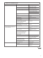
TABLE 6
SUCTION LINE LENGTH/SIZE AND CAPACITY MULTIPLIER
Unit Size
11⁄2 Ton
2 Ton
21⁄2 Ton
3 Ton
31⁄2 Ton
4 Ton
5 Ton
Suction Line
Connection Size
3/4" I.D.
3/4" I.D.
3/4" I.D.
7/8" I.D.
7/8" I.D.
7/8" I.D.
7/8" I.D.
5/8
5/8
5/8
3/4
3/4
7/8
7/8
Suction Line
Run - Feet
3/4*
3/4*
3/4*
7/8*
7/8*
1 1/8*
1 1/8*
25’
50’
100’
150’
—
—
7/8
—
—
—
—
Optional
1.00
1.00
1.00
1.00
1.00
1.00
1.00
Standard
1.00
1.00
1.00
1.00
1.00
1.00
1.00
Optional
—
—
1.00
—
—
—
—
Optional
0.98
0.98
0.96
0.98
0.99
0.99
0.99
Standard
0.99
0.99
0.98
0.99
0.99
0.99
0.99
Optional
—
—
0.99
—
—
—
—
Optional
0.95
0.95
0.94
0.96
0.96
0.96
0.97
Standard
0.96
0.96
0.96
0.97
0.98
0.98
0.98
Optional
—
—
0.97
—
—
—
—
Optional
0.92
0.92
0.91
0.94
0.94
0.95
0.94
Standard
0.93
0.94
0.93
0.95
0.96
0.96
0.97
Optional
—
—
0.95
—
—
—
—
*Standard Line Size
Note: Using suction line larger than shown in chart will result in poor oil return and is not recommended.
11
TABLE 7
LIQUID LINE SIZE — OUTDOOR UNIT ABOVE INDOOR COIL
System
Capacity
Line Size
Connection Line Size
Size
(Inch O.D.)
(Inch I.D.)
Liquid Line Size
Outdoor Unit Above Indoor Coil
(Cooling Only - Does not apply to Heat Pumps)
Total
25
50
75
100
125
150
8
0
0
81
0
0
N/A
0
0
0
0
35
0
0
0
0
0
24
0
0
108
0
0
N/A
0
0
9
0
54
0
0
0
0
0
125
150
N/A
53
70
N/A
16
68
N/A
17
62
7
58
NA
30
22
53
32
79
N/A
49
68
N/A
9
65
N/A
6
58
N/A
53
N/A
24
15
52
20
76
Minimum Vertical Separation - Feet
11⁄2 Ton
3/8ⴖ
2 Ton
3/8ⴖ
21⁄2 Ton
3/8ⴖ
3 Ton
3/8ⴖ
31⁄2 Ton
3/8ⴖ
4 Ton
3/8ⴖ
5 Ton
3/8ⴖ
System
Capacity
1/4
5/16
3/8*
1/4
5/16
3/8*
1/4
5/16
3/8*
5/16
3/8*
5/16
3/8*
3/8*
1/2
3/8*
1/2
Line Size
Connection Line Size
Size
(Inch O.D.)
(Inch I.D.)
0
0
0
0
0
0
0
0
0
0
0
0
0
0
0
0
0
0
0
0
3
0
0
14
0
0
0
0
0
0
0
0
0
0
0
0
0
29
0
0
56
0
0
0
0
0
0
0
0
0
0
0
0
0
55
0
0
98
0
0
0
0
16
0
0
0
0
0
Liquid Line Size
Outdoor unit below Indoor Coil
Total
25
50
75
100
Maximum Vertical Separation - Feet
11⁄2 Ton
3/8ⴖ
2 Ton
3/8ⴖ
21⁄2 Ton
3/8ⴖ
3 Ton
3/8ⴖ
31⁄2 Ton
3/8ⴖ
4 Ton
3/8ⴖ
5 Ton
3/8ⴖ
1/4
5/16
3/8*
1/4
5/16
3/8*
1/4
5/16
3/8*
5/16
3/8*
5/16
3/8*
3/8*
1/2
3/8*
1/2
*Standard Line Size
N/A - Application not recommended.
12
25
25
25
23
25
25
25
25
25
25
25
25
25
25
25
25
25
40
50
50
N/A
36
50
N/A
49
50
50
50
23
50
46
50
50
50
25
62
75
N/A
29
72
N/A
38
68
37
68
4
43
38
56
56
75
9
58
72
N/A
23
70
N/A
27
65
22
63
N/A
36
30
55
44
81
increased power input and non-verifiable performance.
Moisture chemically reacts with the refrigerant and oil to form corrosive hydrofluoric
and hydrochloric acids. These attack motor windings and parts, causing breakdown.
After the system has been leak checked and proven sealed, connect the vacuum
pump and evacuate system to 500 microns. The vacuum pump must be connected
to both the high and low sides of the system through adequate connections. Use
the largest size connections available since restrictive service connections may lead
to false readings because of pressure drop through the fittings.
IMPORTANT: Compressors (especially scroll type) should never be used to evacuate the air conditioning system because internal electrical arcing may result in a
damaged or failed compressor.
START UP AND PERFORMANCE
Even though the unit is factory charged with Refrigerant 410A, the charge must be
checked to the charge table attached to the service panel and adjusted, if required.
Allow a minimum of 5 minutes running. Before analyzing charge, see the instructions on the unit service panel rating plate for marking the total charge.
•
The service valves are not backseating valves. To open the valves, remove the
valve cap with an adjustable wrench. Insert a 3/16” or 5/16” hex wrench into the
stem. Back out counterclockwise until it stops.
•
Replace the valve cap finger tight then tighten an additional 1/8 of a turn for a
metal-to-metal seal.
CHECKING AIRFLOW
The air distribution system has a drastic effect on the life and performance of a system. The duct system is totally controlled by the contractor. For this reason, the
contractor should use only industry-recognized procedures to design and construct
duct system.
The correct air quantity is critical to air conditioning systems. Proper operation, efficiency, compressor life, and humidity control depend on the correct balance
between indoor load and outdoor unit capacity. Excessive indoor airflow increases
the possibility of high humidity problems. Low indoor airflow reduces total capacity,
and causes coil icing. Serious harm can be done to the compressor by low airflow,
such as that caused by refrigerant flooding.
Air conditioning systems require a specified airflow. Each ton of cooling requires
between 350 and 450 cubic feet of air per minute (CFM), or 400 CFM nominally.
Duct design and construction should be carefully done. System performance can be
lowered dramatically through bad planning or workmanship.
Air supply diffusers must be selected and located carefully. They must be sized and
positioned to deliver treated air along the perimeter of the space. If they are too
small for their intended airflow, they become noisy. If they are not located properly,
they cause drafts. Return air grilles must be properly sized to carry air back to the
blower. If they are too small, they also cause noise.
The installers should balance the air distribution system to ensure proper quiet airlow to all rooms in the home. This ensures a comfortable living space.
These simple mathematical formulas can be used to determine the CFM in a residential or light commercial system.
Electric resistance heaters can use
CFM =
volts x amps x 3.414
1.08 x temp rise
Gas furnaces can use
CFM =
BTUH
∆T x 1.08
13
An air velocity meter or airflow hood can give a more accurate reading of the system CFM.
CHECKING REFRIGERANT CHARGE
Charge for all systems should be checked against the Charging Chart inside the
access panel cover. Before using the chart, the indoor conditions must be within
2°F of desired comfort conditions and system must be run until operating conditions
stabilize (15 min. to 30 min.)
! CAUTION
THE TOP OF THE SCROLL COMPRESSOR SHELL IS HOT. TOUCHING THE
COMPRESSOR TOP MAY RESULT IN SERIOUS PERSONAL INJURY.
IMPORTANT: Do not operate the compressor without charge in system.
Addition of R-410A will raise pressures (vapor, liquid and discharge) and lower
vapor temperature.
If adding R-410A raises both vapor pressure and temperature, the unit is overcharged.
IMPORTANT: Use industry-approved charging methods to ensure proper system
charge.
CHARGING BY LIQUID PRESSURE
Liquid pressure method is used for charging systems in the cooling mode when an
expansion valve is used on the evaporator. The service port on the liquid service
valve (small valve) is used for this purpose.
Read and record the outdoor ambient temperature entering the condensing unit,
and the liquid line pressure at the service valve (the small valve). Locate the charging chart attached to the unit. The correct liquid line pressure will be found by finding the intersection of the unit model size and the outdoor ambient temperature.
Adjust the liquid line pressure by either adding refrigerant to raise pressure or
removing refrigerant to lower pressure.
CHARGING UNITS WITH R-410A REFRIGERANT
Checking the charge, or charging units using R-410A refrigerant, differs from those
with R-22. The following procedures apply to units with R-410A refrigerant. These
procedures require outdoor ambient temperature, liquid line pressure and indoor
wet bulb temperature be used.
IMPORTANT: ONLY ADD LIQUID REFRIGERANT CHARGE INTO THE SUCTION
LINE WITH R-410A UNITS. USE A COMMERCIAL METERING DEVICE TO ADD
CHARGE INTO THE SUCTION LINE WITHOUT DAMAGE TO THE COMPRESSOR.
1.
Read and record the outdoor ambient temperature entering the condensing
unit.
2.
Read and record the liquid line pressure at the small service valve.
3.
Read and record the indoor ambient wet bulb temperature entering the indoor
coil.
4.
Use the appropriate charging chart to compare the actual liquid pressure to the
correct pressure as listed on the chart.
5.
R-410A charging charts are listed on the unit.
! CAUTION
R-410A PRESSURES ARE APPROXIMATELY 60% HIGHER THAN R-22
PRESSURES. USE APPROPRIATE CARE WHEN USING THIS REFRIGERANT. FAILURE TO EXERCISE CARE MAY RESULT IN EQUIPMENT DAMAGE, OR PERSONAL INJURY.
14
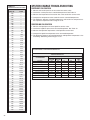
CHARGING BY WEIGHT
For a new installation, evacuation of interconnecting tubing and evaporator coil is
adequate; otherwise, evacuate the entire system. Use the factory charge shown in
Table 1 of these instructions or unit data plate. Note that charge value includes
charge required for 15 ft. of standard size interconnecting liquid line. Calculate actual charge required with installed liquid line size and length using:
1/4” O.D. = 0.2 oz./ft.
5/16” O.D. = 0.3 oz./ft.
3/8” O.D. = 0.5 oz./ft.
1/2” O.D. = 1.0 oz./ft.
With an accurate scale (+/– 1 oz.) or volumetric charging device, adjust charge difference between that shown on the unit data plate and that calculated for the new
system installation. If the entire system has been evacuated, add the total calculated charge.
NOTE: When the total refrigerant charge volume exceeds the values in Tables 8, 9
and 10, the manufacturer recommends installing a crankcase heater and start kit.
TABLE 8
MAXIMUM SYSTEM CHARGE VALUES (-)ANL
(-)ANL Model
Size
18
24
30/31
36/37
42
43
48/49
60
Compressor
Model Number
ZP16K5E
ZP21K5E
ZP25K5E
ZP34K5E
ZP36K5E
ZP38K5E
ZP42K5E
ZP54K5E
Charge Limit Without
Crankcase Heat (3 Phase)
8 lbs.
8 lbs.
8 lbs.
10 lbs.
10 lbs.
10 lbs.
10 lbs.
10 lbs.
Charge Limit Without
Crankcase Heat (1 Phase)
9.6 lbs.
9.6 lbs.
9.6 lbs.
12 lbs.
12 lbs.
12 lbs.
12 lbs.
12 lbs.
TABLE 9
MAXIMUM SYSTEM CHARGE VALUES (-)APL
(-)APL Model
Size
18
24
30
36
42
48
60
Compressor
Model Number
ZP16K5E
ZP20K5E
ZP24K5E
ZP31K5E
ZP36K5E
ZP42K5E
ZP51K5E
Charge Limit Without
Crankcase Heat (1 Phase)
9.6 lbs.
9.6 lbs.
9.6 lbs.
9.6 lbs.
12 lbs.
12 lbs.
12 lbs.
TABLE 10
MAXIMUM SYSTEM CHARGE VALUES (-)APM
(-)APM Model
Size
18
24
30
36
42
48
60
Compressor
Model Number
ZP16K5E
ZP20K5E
ZP24K5E
ZP31K5E
ZP34K5E
ZP42K5E
ZP51K5E
Charge Limit Without
Crankcase Heat (1 Phase)
9.6 lbs.
9.6 lbs.
9.6 lbs.
9.6 lbs.
12 lbs.
12 lbs.
12 lbs.
FINAL LEAK TESTING
After the unit has been properly evacuated and charged, a halogen leak detector
should be used to detect leaks in the system. All piping within the condensing unit,
evaporator, and interconnecting tubing should be checked for leaks. If a leak is
detected, the refrigerant should be recovered before repairing the leak. The Clean
Air Act prohibits releasing refrigerant into the atmosphere.
15
ELECTRICAL WIRING
Field wiring must comply with the National Electric Code (C.E.C. in Canada) and
any applicable local code.
POWER WIRING
It is important that proper electrical power from a commercial utility is available at
the condensing unit contactor. Voltage ranges for operation are shown in Table 11.
Install a branch circuit disconnect within sight of the unit and of adequate size to
handle the starting current (see Tables 1, 2 and 3).
TABLE 11
VOLTAGE RANGES (60 HZ)
Operating Voltage Range at Copeland
Maximum Load Design Conditions for
Compressors
187 - 253
Nameplate Voltage
208/230 (1 Phase)
Power wiring must be run in a rain-tight conduit. Conduit must be run through the
connector panel below the access cover (see Figure 1) and attached to the bottom
of the control box.
! WARNING
NOTE: Connect power wiring to control located in outdoor condensing unit electrical
box. (See wiring diagram attached to unit access panel.)
TURN OFF ELECTRIC POWER AT
THE FUSE BOX OR SERVICE
PANEL BEFORE MAKING ANY
ELECTRICAL CONNECTIONS.
Check all electrical connections, including factory wiring within the unit and make
sure all connections are tight.
DO NOT connect aluminum field wire to the contactor terminals.
ALSO, THE GROUND CONNECTION MUST BE COMPLETED
BEFORE MAKING LINE VOLTAGE
CONNECTIONS. FAILURE TO DO
SO CAN RESULT IN ELECTRICAL
SHOCK, SEVERE PERSONAL
INJURY OR DEATH.
NOTE: Only use copper wire between the circuit disconnect and unit.
GROUNDING
A grounding lug is provided in the control box near the control for a ground wire.
! WARNING
THE UNIT MUST BE PERMANENTLY GROUNDED. FAILURE TO DO SO
CAN CAUSE ELECTRICAL SHOCK RESULTING IN SEVERE PERSONAL
INJURY OR DEATH.
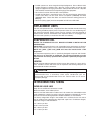
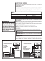
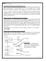
CONTROL WIRING
(See Figure 3)
If the low voltage control wiring is run in conduit with the power supply, Class I insulation is required. Class II insulation is required if run separate. Low voltage wiring
FIGURE 3
CONTROL WIRING FOR GAS OR ELECTRIC HEAT
FOR TYPICAL GAS OR OIL HEAT
TYPICAL THERMOSTAT
SUBBASE
L
BR –
YL –
X –
W/RD –
RD –
Y
G
W
R
BROWN WIRE
YELLOW WIRE
WIRE CONNECTION
WHITE/RED
RED WIRE
TYPICAL GAS OR
OIL FURNACE
TYPICAL CONDENSING
UNIT
W/RD
L
R
Y
C
RD
YL
BR
X
X
X
X
R
W
G
Y
C
FOR TYPICAL ELECTRIC HEAT
TYPICAL THERMOSTAT
SUBBASE
L
W/RD
BR
RD
YL
W/BK
G/BK
PU
X
– WHITE/RED
– BROWN WIRE
– RED WIRE
– YELLOW WIRE
– WHITE WIRE WITH BLACK STRIPE
– GREEN WIRE WITH BLACK STRIPE
– PURPLE WIRE (NOT USED)
– WIRE CONNECTION
TYPICAL CONDENSING
UNIT
L
R
Y
C
W/RD
RD
YL
BR
X
Y
G
X
X
X
W/BK
X
G/BK
X
YL
X
BR
R
PU
16
R
TYPICAL ELECTRIC HEAT
LOW VOLTAGE JUNCTION BOX
X
X
W
may be run through the insulated bushing provided in the 7/8 hole in the base
panel, up to and attached to the pigtails from the bottom of the control box. Conduit
can be run to the base panel if desired by removing the insulated bushing.
NOTE: Use No. 18 AWG solid copper wire at a minimum. If the wire length between
the thermostat and the unit is more than 100 ft., use 16 AWG solid copper wire to
avoid excessive voltage drop.
A thermostat and a 24 volt, 40 VA minimum transformer are required for the control
circuit of the condensing unit. The furnace or the air handler transformer may be
used if sufficient. Verify the correct primary voltage tap is used on the transformer.
NOTE: Reference unit wiring diagram for detailed wiring instructions.
HARD START COMPONENTS
Start components are factory installed.
Start components are required with all non-bleed expansion valve coils.
HIGH AND LOW PRESSURE CONTROLS
(HPC OR LPC)
Pressure controls are factory installed.
These controls keep the compressor from operating in pressure ranges which can cause
damage to the compressor. Both controls are in the low voltage control circuit.
High pressure control (HPC) is an automatic reset which opens near 610 PSIG and closes near 420 PSIG.
The low pressure control (LPC) is an automatic reset which opens near 50 PSIG and
closes near 95 PSIG.
FIELD INSTALLED ACCESSORIES
COMPRESSOR CRANKCASE HEAT (CCH)
While scroll compressors usually do not require crankcase heaters, there are
instances when a heater should be added. Refrigerant migration during the off cycle
can result in a noisy start up. Add a crankcase heater to minimize refrigeration
migration, and to help eliminate any start up noise or bearing “wash out.”
NOTE: A crankcase heater should be installed if: the charge of the system exceeds
the values in Tables 3 and 4, if the system is subject to voltage variations or when a
low ambient control is used for system operation below 55°F.
All heaters are located on the lower half of the compressor shell. Its purpose is to
drive refrigerant from the compressor shell during long off cycles, thus preventing
damage to the compressor during start-up.
At initial start-up or after extended shutdown periods, make sure the heater is energized for at least 12 hours before the compressor is started. (Disconnect switch on
and wall thermostat off.)
NOTE: Reference unit wiring diagram for detailed wiring instructions.
LOW AMBIENT CONTROL (LAC)
This component senses compressor head pressure and shuts the condenser fan off
when the head pressure drops below designated levels. This allows the unit to build a
sufficient head pressure at lower ambient in order to maintain system balance and
obtain improved capacity. Low ambient control should be used on all equipment operated below 65°F ambient.
OUTDOOR UNIT COVERS
Outdoor condensing unit covers are available if the homeowner requests a cover for
their unit. With the complete model number for the unit, the correct cover can be
obtained through an authorized distributor.
! CAUTION
FAILURE TO REMOVE CONDENSING UNIT COVER BEFORE OPERATING
OUTDOOR UNIT CAN CAUSE COMPONENTS TO FAIL.
17
COMFORT CONTROL SYSTEM™
The Integrated Compressor Control (ICC) is an integral part of the Comfort Control
System™ and has the following features:
- Independent compressor and outdoor fan control
- Anti-short cycle protection (3 minute)
- Minimum unit run time (30 seconds)
- 7-segment LED to display status and diagnostics for faster service and accuracy
- High and low pressure switch monitoring
- Power and control voltage monitoring
- Active compressor protection integrated into the control
- Fault Recall capability with power loss memory
- Test Button allows unit operation for start-up diagnostics
- Can be used with a standard thermostat
- Flash diagnostic codes to room thermostat with L terminal
- Sealed compressor relay
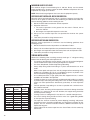
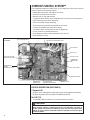
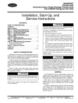
FIGURE 4
ICC BOARD
LOW PRESSURE CONTROL INPUT
O.D. FAN (OFM) RELAY
HIGH PRESSURE CONTROL INPUT
TEST BUTTON
RED LED (Y1)
FIELD LINE VOLTAGE
CONNECTION (ST1)
LOW VOLT FUSE
THERMOSTAT
CONNECTION
(E2)
COMPRESSOR
WIRING
CONNECTOR (ST2)
{
SW2 BUTTON
AMBIENT SENSOR
COMPRESSOR
CONTROL (K2)
ICC (INTEGRATED
COMPRESSOR CONTROL)
7-SEGMENT LED
CONTROL DESCRIPTION (SEE FIGURE 4)
7-Segment LED
• Displays status and diagnostic codes (See Status and Diagnostic Description)
• Displays diagnostic/fault recall (See Test Mode/Fault Recall)
Red LED (Y1)
• Y1 red LED (solid on) indicates Y1 call from thermostat is present
! CAUTION
UNIT MAY START SUDDENLY AND WITHOUT WARNING
Solid red light indicates a thermostat call for unit operation is present at
the ICC control. ICC control will attempt to start unit after short cycle timer
expires or when in Active Protection mode will attempt to restart unit prior
to Lockout mode.
18
Line Voltage Connector (ST1)
• Line voltage is connected to control board at Connector ST1
• Maximum wire size accepted is 6 AWG copper wire
• Torque terminals up to 20 in. lbs. max (Check wire terminations annually)
Compressor Wiring Connectors (ST2)
• Compressor wiring assembly is factory installed (Red – Run, Yellow – Start,
Black – Common)
Compressor Control (K2)
• Sealed single pole compressor relay switch with optical feedback feature (arc
detection)
Thermostat Connector (E2)
•
•
•
•
R – 24VAC from the indoor unit 24VAC transformer (40 VA minimum)
C – 24VAC Common from the indoor unit 24VAC transformer
Y1 – Call for unit operation (cooling)
L – Communicate/flash diagnostic codes to an indoor thermostat that is enabled
with an ‘L’ terminal, ‘check service light’, or similar function
L Terminal Output
•
•
•
•
•
•
Flash 1 – Compressor running extremely long run cycle
Flash 2 – Low or High pressure control trip
Flash 3 – Unit short cycling
Flash 5 – Compressor will not run
Flash 8 – Control mis-operation
Flash 9 – Low control voltage
Low Volt Fuse
• If required replace with 3 A automotive ATC style blade fuse
Low Pressure Control (LPC Input – E14)
• Low-pressure control is factory installed
• Low pressure control is an automatic resetting device
High Pressure Control (HPC Input – E14)
• High-pressure control is factory installed
• High pressure control is an automatic resetting device
Ambient Temperature Sensor
• Included on control but not required in the cooling only condenser application
TEST and SW2 Buttons
• TEST and SW2 buttons used to enter Test and Fault Recall Mode
ICC CONTROL OPERATION
Installation Verification
• 24V AC power on R and C must be present at the ICC for it to operate
• Line voltage must be present at the ICC for the compressor and the outdoor fan
to operate
• When line and 24VAC control voltage is present and there is no Y1 call, or other
diagnostics displayed, the control will display an “O” for standby mode
• If a Y1 call is initiated within 3 minutes of unit power-up or last compressor activation the control will display a flashing “c” and the red Led will activate to solid on
Call for Operation (Y1 Call)
• The ICC has an on/off fan delay of one (1) second.
• The ICC ignores state of LPC for 90 seconds upon compressor start
• The ICC will cause the compressor to be energized for 30 seconds minimum run
time except when TEST button is pushed without a Y1 call
19
3-minute Anti-short Cycle Timer
• The ICC has a built in 3-minute time delay between compressor operations to
protect the compressor against short cycling (Status flashing c).
• The 3-minute time delay can be bypassed when a Y1 call is present by pressing
the TEST button for 1 second and releasing (Status solid on c).
30 Second Minimum Run Timer
• The ICC has a built in 30 second minimum unit run time (Status flashing c).
1 Second Compressor/Fan Delay
• The ICC starts/stops the outdoor fan 1 second after the start/stop of the compressor upon a Y1 call to minimize current inrush and/or voltage droop.
Low Pressure Control (LPC)
• Upon a Y1 call, if the ICC senses an open LPC it will not allow the compressor to
be energized (diagnostic code 21).
• The ICC ignores the LPC for 90 seconds after the compressor is energized.
• After 90 seconds of compressor operation (Y1), the ICC responds to the state of
the LPC.
• If the LPC opens after 90 seconds of compressor run time the ICC will stop the
compressor, display a 21 on the seven-segment display, and flash a 2 on L terminal output
• If there is a Y1 call the compressor will restart upon automatic resetting of the low
pressure switch and the 3-minute anti short cycle timer has expired
• Active Protection – If the LPC opens three (3) times during the same call (Y1),
the ICC will lockout the compressor to keep it from continuing to operate and
flash a L21 on the seven-segment display and continue to flash a 2 on L terminal
output
High Pressure Control (HPC)
• Upon Y1 call, the ICC responds to the state of the HPC.
• If the HPC opens during a Y1 call the ICC will stop the compressor, flash a 23 on
the seven-segment display, and flash a 2 on L terminal output
• If there is a Y1 call the compressor will restart upon automatic resetting of the
high pressure switch and the 3-minute anti short cycle timer has expired
• Active Protection – If the HPC opens three (3) times during the same call (Y1),
the ICC will lockout the compressor to keep it from continuing to operate and
flash a L23 on the seven-segment display and continue to flash a 2 on L terminal
output
ACTIVE COMPRESSOR PROTECTION MODE
Active Compressor Protection
• The ICC actively protects the compressor from harmful operation during a fault
condition.
• The ICC will protect the compressor by locking out if it senses three (3) trips of
either low or high pressure controls during the same Y1 call (There are no additional re-tries after a pressure switch lockout)
• The ICC will de-energize the compressor if it senses a compressor fault (will try
to restart the compressor for up to 6 hours before a lockout)
Exiting Active Compressor Protection Lockout
There are three methods to reset the ICC after an active protection lockout:
• Cycle line voltage to the unit
• Cycle 24VAC to the ICC (R or C connection)
• Push the TEST button down for 1 second and release (The ICC will attempt to
start the unit when the TEST button is pressed and released)
20
TEST AND FAULT RECALL MODES
Test Mode (TEST Button)
• The TEST mode resets the ICC from any active protection lockout mode or
bypasses the 3-minute anti-short cycle timer and energizes the unit
• To enter TEST mode press TEST button with an insulated probe for 1 second
and then release:
o If a Y1 call is present and a flashing “c” is indicated on the 7-segment display, a
“t” will momentarily flash on the 7-segment display, the unit will energize, and
the display will change to a steady “c”
o If a Y1 call is not present a steady “t” appears on the 7-segment display and the
unit will energize for a maximum of 5 seconds (times out)
• A Y1 call during TEST mode causes the ICC to exit TEST and enter a normal unit
operation mode
• Note: If Y1 is present at the ICC upon exit from TEST mode the unit will continue
to operate
Fault Recall Mode (TEST and SW2 Buttons)
• To enter FAULT RECALL mode press both TEST and SW2 buttons at the same
time with insulated probes for 1 second and release.
• Upon entering and exiting the FAULT RECALL mode, the top and bottom segments of the 7-segment display will be activated.
• The ICC control will automatically scroll through stored faults on the 7-segment
display.
• Each fault is displayed one time with the top segment of the 7-segment display
activated between faults.
• Each fault is displayed with the most recent fault displayed first.
• A maximum of six individual faults can be stored.
• A maximum of 3 consecutive identical faults are stored.
• A “0” will be displayed when no faults are stored.
• The ICC will automatically exit the FAULT RECALL mode after displaying stored
faults.
Clear Fault History (TEST and SW2 Buttons)
• To clear FAULT HISTORY press both TEST and SW2 buttons at the same time
with insulated probes for 5 seconds and release.
• The top and bottom segments of the 7-segment display will be activated and
flash to indicate the history has been cleared.
(*) – Indicates flash code will be an output on the ICC “L” terminal to the indoor
thermostat “L” terminal. Unless a diagnostic/fault is manually cleared by cycling
power or pressing the TEST button the flash code will continue at the L terminal for
up to 20 seconds after the start of a successful call for unit operation.
21
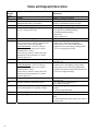
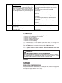
Status and Diagnostic Description
7 -Segment
Display
Code
0
c
c Flashing
F
1 (*)
2 (*)
21 (***)
L21 (**)
23 (***)
22
Diagnostic Description
Status / Possible Cause -Troubleshooting
Information
Standby
Y1
Anti-Short Cycle Timer (3 minutes) or
Minimum Run Timer (30 seconds)
ICC Board Fuse Open
Compressor Running Extremely Long Run
Cycle (Cooling mode only)
Standby - No call for operation
First Stage or Single Stage Unit Operation
Waiting for anti-short cycle timer to expire
Waiting for minimum run timer to expire
1. Low voltage wiring damage or miswired
1. Low refrigerant charge
2. Air ducts have substantial leakage
3. Check thermostat operation
4. Dirty filter
5. Dirty outdoor coil
1. (See faults 21, L21, 23, L23)
1. Unit is low on refrigerant charge
2. Indoor coil is frozen (cooling mode)
3. Dirty indoor coil or filter (cooling mode)
4. Indoor blower is not running (cooling mode)
5. TEV is not operating correctly
Pressure Control Trip (L terminal output only)
Low Pressure Control Trip
Note: Low-pressure control is ignored for 90
seconds after call for unit operation.
Active Protection – The ICC will try to
restart the unit after the pressure control
automatically re-closes.
Unit will try to restart 3 times in the same
thermostat call for operation (Y1) before
lockout (fault L21).
Lockout - Low Pressure Control Trip (**)
L23 (**)
High Pressure Control Trip
Active Protection – The ICC will try to
restart the unit after the pressure control
automatically re-closes.
Unit will try to restart 3 times in the same
thermostat call for operation (Y1) before
lockout (fault L23)
Lockout - High Pressure Control Trip (**)
25
Outdoor Ambient Temperature Sensor
27
Abnormal Low Line or No Line Voltage
(See unit nameplate for operating voltage)
28
3 (*)
Abnormal High Line Voltage
Short Cycling
LPC tripped three consecutive times in same
thermostat call
1. Outdoor coil is dirty (cooling mode)
2. Outdoor fan is not running (cooling mode)
3. Dirty indoor coil or filter (heat pump mode)
4. Liquid line restriction (filter drier blocked, etc.)
5. Excessive refrigerant charge
HPC tripped three consecutive times in same
thermostat call
1. ICC board sensor damaged (ICC
will continue to operate)
1. Check incoming line voltage to the disconnect
and unit
2. Check wiring connections
1. Check line voltage
1. Check thermostat for intermittent demand
signal
2. Check thermostat location in zone (too close to
discharge grill)
5 (*) (***)
Compressor will not run
Active Protection – After detecting compressor
will not run the ICC control will shut the unit
down. The control will try to restart the unit
every 5 minutes for 4 tries. After that, the ICC
will attempt a restart every 20 minutes up to 6
hours.
L5 (**)
Lockout – Check Compressor (**)
8 (*)
ICC Board Mis-operation
ICC Board Mis-operation (L terminal
output only)
ICC Secondary Voltage Low
(Less than 18V)
9 (*)
1. Check for damaged, miswired, or wrong run
capacitor
2. Check for damaged or miswired start capacitor
and relay
3. Check voltage levels at ICC board and
compressor
4. Check for broken wires, loose connectors, or
miswired
5. Check compressor motor windings for
continuity
6. Check for open compressor internal protector
7. Check for excessive liquid refrigerant in
compressor
After 6 hours of attempted unit restart ICC
control
1. Check ICC board compressor relay
1. Check ICC board compressor relay
1. Check transformer for miswiring or
overloading.
L Terminal Output
•
•
•
•
•
•
Flash 1 – Compressor running extremely long run cycle
Flash 2 – Low or High pressure control trip
Flash 3 – Unit short cycling
Flash 5 – Compressor will not run
Flash 8 – Control mis-operation
Flash 9 – Low control voltage
(**) – Lockout modes are reset by either cycling line voltage, low voltage, or by
pressing control TEST button for 1 second. The control will attempt to start the unit
when the TEST button is pressed and released (See TEST button label)
(***) – Caution: Indicates Active Protection. Unit will attempt to restart automatically.
! CAUTION
UNIT MAY START SUDDENLY AND WITHOUT WARNING
Solid red light indicates a thermostat call for unit operation is present at the ICC.
ICC will attempt to start unit after short cycle timer expires or when in Active
Protection mode will attempt to restart unit prior to Lockout mode.
NOTE: For Additional Questions or Comments concerning the ICC, call 1-888923-2323.
SERVICE
SINGLE-POLE COMPRESSOR RELAY
Integrated Compressor Control Relay is a single-pole relay used on all single phase
units up through 5 tons. Caution must be exercised when servicing as only one leg
of the power supply is broken with the relay.
23
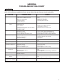
TROUBLESHOOTING
IMPORTANT: The JEZ series units with the ICC (Integrated Compressor Control)
provide status and diagnostic information that greatly enhances the ability to quickly
diagnose system faults. Use the following troubleshooting guides as another tool in
system diagnostics.
NOTE: In diagnosing common faults in the cooling system, develop a logical
thought pattern as used by experienced technicians. The charts which follow are
not intended to be an answer to all problems but only to guide the technician’s
troubleshooting. Through a series of yes and no answers, follow the logical path to
a likely conclusion.
A novice technician should use these charts like a road map. Remember that the
chart should clarify a logical path to the solution.
ELECTRICAL CHECKS FLOW CHART
Thermostat calling, but unit not cooling
Unit Running?
Yes
Check ICC fault history,
go to Mechanical check for cooling
No
Control Voltage powering ICC?
No
Check indoor
transformer/Fuse/
Wiring/Connections
No
Check thermostat/24 VAC
on Y Terminal
Yes
Y1 Red LED on?
Yes
Flashing c
7 Segment Display
Character?
Other Fault
L__
Short cycle delay is active.
Test button will override
delay.
24
Indicates control in lockout
Check fault history.
See diagnostic label on
control box cover.
COOLING MECHANICAL CHECKS FLOW CHART
Unit Running?
YES
NO
Pressure problems?
Go to Electrical
Checks Flow Chart
High Head Pressure
Low Head Pressure
Low Suction Pressure
Dirty Outdoor Coil
Low on Charge
Dirty Filters
Inoperative Outdoor Fan
Open IPR Valve
Dirty Indoor Coil
Overcharge
Low Ambient Temperature
Inadequate Indoor Air Flow
Recirculation of
Outdoor Air
Inoperative Compressor
Valves
Inoperative Indoor Blower
Non-condensibles
Outdoor Check Valve
Closed
Low on Charge
Higher than Ambient
Air Entering Outdoor Coil
Wrong Outdoor Fan Rotation
Restricted Indoor
Metering Device
Restricted Indoor
Metering Device
Restriction in System
Restricted
Filter Drier
Recirculation of
Indoor Air
Wrong Indoor
Blower Rotation
Inadequate Ducts
Outdoor Check Valve Closed
Restricted Filter Drier
25
SYSTEM CHARGE TROUBLESHOOTING
TABLE 12
TEMPERATURE PRESSURE CHART
26
TEMP
(Deg. F)
R-410A
PSIG
-150
-140
-130
-120
-110
-100
-90
-80
-70
-60
-50
-40
-35
-30
-25
-20
-15
-10
-5
0
5
10
15
20
25
30
35
40
45
50
55
60
65
70
75
80
85
90
95
100
105
110
115
120
125
130
135
140
145
150
—
—
—
—
—
—
—
—
—
0.4
5.1
10.9
14.2
17.9
22.0
26.4
31.3
36.5
42.2
48.4
55.1
62.4
70.2
78.5
87.5
97.2
107.5
118.5
130.2
142.7
156.0
170.1
185.1
201.0
217.8
235.6
254.5
274.3
295.3
317.4
340.6
365.1
390.9
418.0
446.5
476.5
508.0
541.2
576.0
612.8
SUPERHEAT CALCULATION
1.
2.
3.
4.
5.
Measure the suction pressure at the suction line service valve.
Convert the suction pressure to saturated temperature. See Table 12.
Measure the temperature of the suction line at the suction line service valve.
Compare the temperature to the suction line to the saturated temperature.
The difference between saturated temperature and suction line temperature is
the superheat. Superheat normal range 9° to 16°.
SUBCOOLING CALCULATION
1.
2.
3.
4.
5.
Measure the liquid pressure at the liquid line service valve.
Convert the liquid line pressure to saturated temperature. See Table 13.
Measure the liquid line temperature at the liquid line service valve.
Compare the liquid line temperature to the saturated temperature.
The difference between saturated temperature and liquid line temperature is the
subcooling. Subcooling normal range 5° to 14°.
TABLE 13
AIR CONDITIONING SYSTEM TROUBLESHOOTING TIPS
AIR CONDITIONING SYSTEM
TROUBLESHOOTING TIPS
INDICATORS
SYSTEM PROBLEM
Overcharge
DISCHARGE SUCTION
COMPRESSOR
SUPERHEAT SUBCOOLING
PRESSURE PRESSURE
AMPS
High
High
Low
High
High
Undercharge
Low
Low
High
Low
Low
Liquid Restriction (Drier)
Low
Low
High
High
Low
Low Evaporator Airflow
Low
Low
Low
Low
Low
Dirty Condenser
High
High
Low
Low
High
Low
Low Outside Ambient Temperature
Low
Low
High
High
Inefficient Compressor
Low
High
High
High
Low
TXV Sensing Bulb Charge Lost
Low
Low
High
High
Low
Poorly Insulated Sensing Bulb
High
High
Low
Low
High
GENERAL
TROUBLESHOOTING CHART
!
WARNING
DISCONNECT ALL POWER TO UNIT BEFORE SERVICING. RELAY MAY BREAK ONLY ONE SIDE. FAILURE TO
SHUT OFF POWER CAN CAUSE ELECTRICAL SHOCK RESULTING IN PERSONAL INJURY OR DEATH.
SYMPTOM
POSSIBLE CAUSE
Unit will not run
• Power off or loose electrical connection
• Thermostat out of calibration-set too high
• Blown fuses / tripped breaker
• Transformer defective
• Pressure control open
Outdoor fan runs, compressor
doesn’t
• Run or start capacitor defective
• Start relay defective
• Loose connection
• Compressor stuck, grounded or open motor winding,
open internal overload.
• Low voltage condition
Insufficient cooling
Compressor short cycles
•
•
•
•
Improperly sized unit
Improper indoor airflow
Incorrect refrigerant charge
Air, non-condensibles or moisture in system
• Incorrect voltage
• Defective overload protector
• Refrigerant undercharge
Registers sweat
REMEDY
•
•
•
•
•
Check for correct voltage at control in condensing unit
Reset
Check for 24 volts at control
Replace fuses / reset breaker
Check wiring-replace transformer
• Check for correct voltage at compressor check & tighten all connections
• Wait at least 2 hours for overload to reset.
•
•
•
•
Recalculate load
Check - should be approximately 400 CFM per ton.
Charge per procedure attached to unit service panel
Recover refrigerant, evacuate & recharge, add filter drier
• Voltage must be ± 10% of
nameplate marking when unit is operating.
• Add refrigerant
• Low indoor airflow
• Increase speed of blower or reduce restriction - replace air
filter
High head-low vapor pressures
• Restriction in liquid line, expansion device or filter drier
• Remove or replace defective component
High head-high or normal vapor
pressure - Cooling mode
•
•
•
•
•
•
•
•
Low vapor - cool compressor iced indoor coil
• Low indoor airflow
Dirty outdoor coil
Refrigerant overcharge
Outdoor fan not running
Air or non-condensibles in system
• Operating below 65°F outdoors
• Moisture in system
High vapor pressure
Fluctuating head & vapor
pressures
Gurgle or pulsing noise at
expansion device or liquid line
Clean coil
Correct system charge
Repair or replace
Recover refrigerant, evacuate & recharge
• Increase speed of blower or reduce restriction - replace air
filter
• Add Low Ambient Kit
• Recover refrigerant - evacuate & recharge - add filter drier
• Excessive load
• Defective compressor
• Recheck load calculation
• TXV hunting
• Air or non-condensibles in system
• Check TXV bulb clamp - check air distribution on coil - replace
TXV
• Recover refrigerant, evacuate & recharge
• Air or non-condensibles in system
• Recover refrigerant, evacuate & recharge
27
GENERAL SERVICE ANALYZER CHARTS
COMPRESSOR OVERHEATING
SYMPTOMS
POSSIBLE CAUSE
CHECK/REMEDIES
High superheat
Low charge
Check system charge
Faulty metering device
Restricted cap tube, TEV (TXV)
Power element superheat
adjustment
Foreign matter stopping flow
High internal load
Hot air (attic) entering return
Heat source on; mis-wired or
faulty control
Restriction in liquid line
Drier plugged
Line kinked
Low head pressure
Low charge
Operating in low ambient
temperatures
Low voltage
Suction or liquid line subjected
to high heat source
Hot attic
Hot water line
Loose wire connections
Check wiring
Power company problem,
transformer
Have problem corrected before
diagnosis continues
Undersized wire feeding unit
Correct and complete diagnosis
High voltage
Power company problem
Have problem corrected
High head pressure
Overcharge
Check system charge
Dirty heat pump coil
Clean coil
Faulty or wrong size
heat pump fan motor
Replace fan motor
Faulty fan blade
or wrong rotation
Replace fan blade
Recirculation of air
Correct installation
Replace with correct rotation motor
Additional Heat Source
Check for dryer vent near unit
Check for recirculation from
other equipment
Short cycling of compressor
Non-condensibles
Recover refrigerant, Evacuate and
recharge system
Equipment not matched
Correct mis-match
Faulty pressure control
Replace pressure control
Loose wiring
Check unit wiring
Thermostat
Located in supply air stream
Differential setting too close
Customer misuse
TEV
Internal foreign matter
Power element failure
Valve too small
Distributor tube/tubes restricted
CONTINUED
28
SYMPTOMS
POSSIBLE CAUSE
CHECK OR REMEDIES
Short cycling of compressor (cont.)
Low charge
Check system charge
Low evaporator air flow
Dirty coil
Dirty filter
Duct too small or restricted
Faulty run capacitor
Replace
Faulty internal overload
Replace compressor
ELECTRICAL (See Control Diagnostics)
SYMPTOMS
POSSIBLE CAUSE
CHECK OR REMEDIES
No voltage on line side
of control board
Blown fuses or tripped circuit breaker
Check for short in wiring or unit
Improper wiring
Re-check wiring diagram
Improper voltage
High voltage
Wrong unit
Power supply problem
Low voltage
Wrong unit
Power supply problem
Wiring undersized
Loose connections
CONTAMINATION
SYMPTOMS
POSSIBLE CAUSE
CHECK OR REMEDIES
Moisture
Poor evacuation on installation
or during service
In each case, the cure is the same.
Recover refrigerant. Add filter drier,
evacuate and re-charge
High head pressure
Non-condensibles air
Unusual head and suction readings
Wrong refrigerant
Foreign Mattercopper filings
Copper tubing cuttings
Copper oxide
Dirty copper piping
Welding scale
Nitrogen not used
Soldering flux
Adding flux before seating
copper part way
Excess soft solder
Wrong solder material
CONTINUED
29
LOSS OF LUBRICATION
SYMPTOMS
POSSIBLE CAUSE
CHECK OR REMEDIES
Compressor failures
Line tubing too long
Add oil to the recommended level
Line tubing too large
Reduce pipe size to improve
oil return
Low suction pressure
Low charge
Check system charge
Refrigerant leaks
Repair and recharge
Cold, Noisy compressor - Slugging
Dilution of Oil with Refrigerant
Observe piping guidelines
Noisy compressor
Migration
Check crankcase heater
Cold, sweating compressor
Flooding
Check system charge
Low Load
Reduced air flow
Dirty filter
Dirty coil
Wrong duct size
Restricted duct
Thermostat setting
Short cycling of compressor
Advise customer
Faulty pressure control
Replace control
Loose wiring
Check all control wires
Thermostat
In supply air stream,
out of calibration,
Customer misuse
FLOODED STARTS
SYMPTOMS
POSSIBLE CAUSES
CHECK OR REMEDIES
Liquid in the compressor shell
Faulty or missing crankcase heater
Replace crankcase heater
Too much liquid in system
Incorrect piping
Check Piping guidelines
Overcharge
Check and adjust charge
SYMPTOMS
POSSIBLE CAUSES
CHECK OR REMEDIES
On start up
Incorrect piping
Review pipe size guidelines
TEV hunting when running
Oversized TEV
Check TEV application
SYMPTOMS
POSSIBLE CAUSES
CHECK OR REMEDIES
Poor system control
using a TEV
Loose sensing bulb
Secure the bulb and insulate
Bulb in wrong location
Relocate bulb
SLUGGING
FLOODING
Wrong size TEV
Use correct replacement
Improper superheat setting
Adjust, if possible;
Replace, if not
CONTINUED
30
THERMOSTATIC EXPANSION VALVES
SYMPTOMS
POSSIBLE CAUSE
CHECK OR REMEDIES
High Superheat, Low Suction Pressure
Moisture freezing and blocking valve
Recover charge, install filter-drier,
evacuate system, recharge
Dirt or foreign material blocking valve
Recover charge, install filter-drier,
evacuate system, recharge
Low refrigerant charge
Correct the charge
Vapor bubbles in liquid line
Remove restriction in liquid line
Correct the refrigerant charge
Remove non-condensible gases
Size liquid line correctly
Valve feeds too much refrigerant,
with low superheat and higher than
mal suction pressure
Compressor flood back upon start up
Misapplication of internally equalized
valve
Use correct TEV
Plugged external equalizer line
Remove external equalizer line
restriction
Undersized TEV
Replace with correct valve
Loss of charge from power
head sensing bulb
Replace power head or complete
TEV
Charge migration from sensing bulb
to power head (Warm power head
with warm, wet cloth. Does valve
operate correctly now?)
Ensure TEV is warmer than
sensing bulb
Improper superheat adjustment
(Only applicable to TEV with adjustable
superheat settings)
Adjust superheat setting counterclockwise
Moisture causing valve to stick open.
Recover refrigerant, replace filterdrier, evacuate system and then norrecharge
Dirt or foreign material causing
valve to stick open
Recover refrigerant, replace filterdrier, evacuate system and
recharge
TEV seat leak (A gurgling or hissing
sound is heard AT THE TEV during
the off cycle, if this is the cause.)
NOT APPLICABLE TO BLEED
PORT VALVES.
Replace the TEV
Oversized TEV
Install correct TEV
Incorrect sensing bulb location
Install bulb with two mounting
straps, in 2:00 or 4:00 position on
suction line, with insulation
Low superheat adjustment
(only applicable to TEV with
adjustable superheat setting)
Turn superheat adjustment
clockwise
Incorrectly installed, or restricted
external equalizer line
Remove restriction, or relocate
external equalizer
Refrigerant drainage from flooded
evaporator
Install trap riser to the top of the
evaporator coil
Compressor in cold location
Install crankcase heater on
compressor
CONTINUED
31
THERMOSTATIC EXPANSION VALVES
SYMPTOMS
POSSIBLE CAUSE
CHECK OR REMEDIES
Superheat is low to normal
with low suction pressure
Unequal evaporator circuit loading
Ensure air flow is equally distributed
through evaporator
Check for blocked distributor
tubes
Low load or airflow entering
evaporator coil
Ensure blower is moving proper air
CFM
Remove/Correct any air flow
restriction
Superheat and suction
pressure fluctuate (valve is hunting)
Expansion valve is oversized
Install correct TEV
Sensing bulb is affected by liquid
refrigerant or refrigerant oil flowing
through suction line
Relocate sensing bulb in another
position around the circumference of
the suction line
Unequal refrigerant flow through
evaporator circuits
Ensure proper distributor piston is
inserted in RCBA or RCHA coil
Ensure sensing bulb is located
properly
Check for blocked distributor
tubes
Valve does not regulate at all
Improper superheat adjustment
(only possible with TEV having
superheat adjustment)
Replace TEV or adjust superheat
Moisture freezing and partially
blocking TEV
Recover refrigerant, change filterdrier, evacuate system and
recharge
External equalizer line not connected
or line plugged
Connect equalizer line in proper
location, or remove any blockage
Sensing bulb lost its operating charge
Replace TEV
Valve body damaged during soldering
or by improper installation
Replace TEV
CONTINUED
32
FIGURE 5
JEZ-DIAGNOSTIC LABEL
C aution –
UNI T M A Y ST A R T SUDDE NL Y A ND W I T H OUT W A R NI NG
Solid red L E D light indicates a thermostat call for unit operation is present at the ICC.
ICC will attempt to start unit after short cycle timer expires or when in Active
Protection mode will attempt to restart unit prior to L ockout mode.
7 - Segment
Display C ode
Diagnostic Descr iption
Status / Possible C ause -T r oubleshooting I nfor mation
0
c
C
c or C
F lashing
d
d F lashing
Standby
Y1
Y2
Anti-Short Cycle Timer (3 minutes) or
Minimum R un Timer (30 seconds)
Defrost
Abnormal Defrost Condition
(Defrost control exceeds maximum defrost time)
ICC Fuse Open
Compressor R unning E xtremely L ong R un Cycle
(Cooling mode only)
Standby - No call for operation
First Stage or Single Stage Unit Operation
Second Stage Unit Operation (2-stage unit only)
W aiting for anti-short cycle timer to expire
W aiting for minimum run timer to expire
Heat Pump Defrost Operation
1. Defrost control miswired
2. Faulty defrost control
1. L ow voltage wiring damage or miswired
1. L ow refrigerant charge
2. Air ducts have substantial leakage
3. Check thermostat operation
4. Y 2 thermostat signal may not be connected (2-stage units only)
5. Dirty outdoor coil
1. (See faults 21, L 21, 23, L 23)
1. Unit is low on refrigerant charge
2. Indoor coil is frozen (cooling mode)
3. Dirty indoor coil or filter (cooling mode)
4. Indoor blower is not running (cooling mode)
5. Outdoor coil is frozen (heat pump mode)
6. Outdoor fan is not running (heat pump mode)
7. TE V is not operating correctly
L PC tripped three consecutive times in same thermostat call
1. Outdoor coil is dirty (cooling mode)
2. Outdoor fan is not running (cooling mode)
3. Dirty indoor coil or filter (heat pump mode)
4. Indoor blower is not running (heat pump mode)
5. L iquid line restriction (filter drier blocked, etc.)
6. E xcessive refrigerant charge
HPC tripped three consecutive times in same thermostat call
1. ICC sensor damaged (ICC will continue to operate)
1. Check incoming line voltage to the disconnect and unit
2. Check wiring connections
1. Check line voltage
1. Check thermostat for intermittent demand signal
2. Check thermostat location in zone (too close to discharge grill)
1. Check for damaged, miswired, or wrong run capacitor
2. Check for damaged or miswired start capacitor and relay
3. Check voltage levels at ICC and compressor
4. Check for broken wires, loose connectors, or miswired
5. Check compressor motor windings for continuity
6. Check for open compressor internal protector
7. Check for excessive liquid refrigerant in compressor
L ockout after 6 hours of attempted restart
1. Check ICC compressor relay
1. Check ICC compressor relay
1. Check transformer for miswiring or overloading.
F
1 (*)
2 (*)
21 (***)
L 21 (**)
23 (***)
L 23 (**)
25
27
28
3 (*)
Pressure Control T rip (L terminal output only)
L ow Pressure Control Trip
Note: L ow-pressure control is ignored for 90 seconds after call
for unit operation.
A ctive Pr otection – T he ICC will try to restart the unit after the
pressure control automatically re-closes.
Unit will try to restart 3 times in the same thermostat call for
operation (Y 1) before lockout (fault L 21).
L ockout - L ow Pressure Control Trip (**)
High Pressure Control Trip
A ctive Pr otection – T he ICC will try to restart the unit after the
pressure control automatically re-closes.
Unit will try to restart 3 times in the same thermostat call for
operation (Y 1) before lockout (fault L 23)
L ockout - High Pressure Control Trip (**)
Outdoor Ambient Temperature Sensor
Abnormal L ow L ine or No L ine V oltage
(See unit nameplate for operating voltage)
Abnormal High L ine V oltage
Short Cycling
5 (*) (***)
Compressor will not run
A ctive Pr otection – A fter detecting compressor will not run the
ICC will shut the unit down. The control will try to restart the
unit every 5 minutes for 4 tries. A fter that, the ICC will attempt
a restart every 20 minutes up to 6 hours.
L 5 (**)
8 (*)
9 (*)
L ockout – Check Compressor (**)
ICC M is-operation
ICC M is-operation (L terminal output only)
ICC Secondary V oltage L ow (< 18V )
ICC – Integrated Compressor Control
(*)
– Indicates the display code will be flashed as an output on the ICC “L ” terminal. For example 2 flashes (blinks) from the “L ” terminal output
indicates a pressure control trip.
(** ) – L ockout modes are reset by removing line voltage, low voltage, or by pressing control T E ST button for 1 second.
The control will attempt to start the unit when the T E ST button is pressed and released (See T E ST button label)
(***) – I ndicates A ctive Pr otection. Unit will attempt to r estar t automatically.
R ed L E D
Display C ode
Diagnostic Descr iption
Status I nfor mation
Solid On
Call for Unit Operation
Y 1 call is present from the room thermostat at the control
F or A dditional Questions or C omments concer ning the I C C call 1-888-923-2323
92-102221-01-02
33
FIGURE 6
JEZ TEST & FAULT RECALL LABEL
T E S T MODE MANUAL OP E R AT ION (T E S T )
T he T E S T mode res ets the IC C (Integrated C ompress or C ontrol) from any lockout mode or
bypas ses compress or anti-s hort cycle delay timer. T o enter T E S T mode pres s T E S T button
with ins ulated probe for 1 s econd and then release. A “t” will display on the 7-segment
dis play. T he “t” will remain unless an error is detected or a call for Y 1 is present (red LE D
Y 1 is on). A call for Y 1 during T E S T caus es the control to exit T E S T and enter a normal
unit operation mode. During T E S T mode the IC C will continue to activate the unit for up to
5 s econds (times out). T o exit T E S T mode at anytime pres s T E S T button with ins ulated
probe for 1 s econd and release. Note: If Y 1 is pres ent the IC C will exit from T E S T mode the
and unit will continue to run.
F AUL T R E C AL L OP E R AT ION (T E S T and S W 2)
T o enter F A UL T R E C AL L mode press both T E S T and S W 2 buttons at the s ame time with
ins ulated probes for 1 s econd and releas e. Upon entering and exiting the F AUL T R E C AL L
mode, the top and bottom segments of the 7-s egment dis play will be activated. T he IC C will
automatically s croll through s tored faults on the 7-segment dis play. E ach fault is dis played
one time with the top segment of the 7-s egment display activated between faults . E ach
fault is dis played with the most recent fault dis played firs t. An “O” will be dis played when no
faults are s tored. T he IC C will automatically exit the F AUL T R E C AL L mode after displaying
s tored faults.
An example of one LP C fault and one HP C fault scrolled on the dis play is as s hown below:
C L E AR F AUL T HIS T OR Y (T E S T and S W 2)
T o clear F AUL T HIS T OR Y press both T E S T and S W2 buttons at the s ame time with
ins ulated probes for 5 s econds and releas e. T he top and bottom s egments of the 7s egment dis play will be activated and flas h to indicate the history has been cleared.
T es t button
C AUT ION
T he unit may s tart suddenly without
warning when a solid red LE D light is
pres ent. T he LE D light indicates a call
for unit operation (Y 1) from the
thermos tat to the IC C control.
S W 2 B utton
7- S egment LE D
92-102221-02-01
34
FIGURE 7
WIRING DIAGRAM
35
36
CM 0109