1
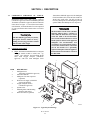
WORLD CLASS 3000 OXYGEN
ANALYZER (CENELEC) WITH
IFT 3000 INTELLIGENT FIELD
TRANSMITTER (CENELEC)
Instruction Bulletin
NOTICE:
IB-106-300NFX
Rev. 4.1
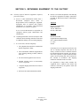
World Class 3000 Probe
HPS 3000
Part No. _______________
Serial No. _______________
Order No. _______________
Part No. _______________
Serial No. _______________
Order No. _______________
IFT 3000
MPS 3000
Part No. _______________
Serial No. _______________
Order No. _______________
Part No. _______________
Serial No. _______________
Order No. _______________
The equipment described in this
Instruction Bulletin is manufactured by:
Rosemount Ireland
151 Shannon Industrial Estate
Co. Clare
Ireland
lNTRoDUCT’oN:
THIS SAFRY
DATA SHEm APPLIES TO INTELEGENT
FIELD TRANSMllTER
(Im3000),
NPE
No. 11105691.
THE APPARATUS
IS CERTIFIED
EExd IIB T6.:
ISSeP CERTIFICATE
No.
THIS APPARATUS
HAS BEEN DESIGNED AND MANUFACTURED
TO OPERATE
SAFELY IN CERTAIN NPES
OF POTENTIALLY
EXPLOSIVE ATMOSPHERES.
IT 1s ESSENTIAL
THAT THE EQUIPMENT
IS NOT TAMPERED
WITH OR DAMAGED IN ANY WAY WHICH
MIGHT LEAD TO A REDUCTION
IN IT’S ABILITY TO OPERATE SAFELY IN SUCH POTENTIALLY
EXPLOSIVE ATMOSPHERES.
FOR YOUR OWN SAFETY AND THE SAFETY
OF OTHERS
PLEASE BRING ANY DAMAGE TO THE ATTENTION OF THE RESPONSIBLE
AUTHORITY.
THIS APPARATUS
HAS BEEN DESIGNED AND MANUFACmRED
IN ACCORDANCE
WITH EUROPEAN
STANDARDS
EN50014
8c EN50018.
INSTALLATION
MAINTENANCE
AND REPAIR MUST BE IN ACCORDANCE.
WITH THE OFFICAL “C@ES
OF
PRACTICE ON THE INSTAIATION
AND MAINTAINANCE
OF ELEC@ICAL
APPARATUS
IN POTENTIALLY
EXPLOSIVE ATMOSPHERES”
FOR THE COUl@Y
OF INSTALLATION
(EXAMPLE:
8~5345
IN GREAT BRITAIN).
ONLY APPROPR~ATLY
TRAINED PERSONNEL
ARE AUTHORISED
TO PERFORM ANY W0RK ON THIS EQUIPMENT.
SUCH PERSONNEL
IN
ADDITION TO OPERATING TO THE ABOVE
MENTlONED
SAFETY STANDARDS,
SHOULD TAKE
NOTE OF THE FOLLOWING SAFETY ISSUES.
(1, FLAMEPROOF
APPARATUS
OR NON FLAMEPROOF
APPARATUS.
THE ROSEMOUNT
ENCODE SHEETS (PRODUCT
ORDERING
MATRIX) ALLOWS A CUSTOMER
TO ORDER EITHER THE HAZARDOUS
AREA (FLAMEPROOF)
VERSION
OF THE IFT3000
OR THE NON HAZARDOUS
AREA VERSION.
THE HAZARDOUS
AREA VERSION
HAS THE
SYMBOL “EExd” ON THE APPARATUS
hIAMEPLATE. THE NON HAZARDOUS
AREA VERSION
DOES NOT. ENSURE THAT IF YOU HAVE RECEIVED THE NON HAZARDOUS
AREA VERSION
THAT YOU DO NOT INSTALL IT IN APOTENTIALLY
EXPLOSIVE
ENVIRONMENT.
(2)
POWER
DOWN
PROCEDURE:
ISOLATION OF ELECTRICAL SUPPLY: THIS PIECE OF APPARATUS
IS NOT ITSELF FIT-I-ED
WITH A MEANS OF ELECTRICAL
ISOLATION.
CONSULT YOUR LOCAL CODES OF PRACTICE
ON THE INSTALLATION
AND MAlNTAlNAhlCE
OF ELECTRICAL APPARATUS
IN POTENTIALLY
EXPLOSIVE ATMOSPHRES
(835345
IN IBRITAIN) FOR INSTRUCTION
ON THE ISOLATION OF
ELECTRICAL SUPPLY TO THE APPARATUS.
FURTHER MORE THERE MUST BE “EFFECTIVE
MEASURES TO PREVENT THE RESTORATION
OF SUPPLY TO THE APPARATUS
WHILE THE
RISK OF EXPOSING
UNPROTECTED
LIVE CONDUCTORS
TO AN EXPLOSIVE ATMOSPHERE
CONTlNUES”:BS5345
PAPT 1 1989
SECTION 18.
RESTORATION
OF SUPPLY FOR-EL-ICAL
TESTlNG: “WHERE, FOR PURPOSES
OF
ELECTRICAL TESTING, IT IS ESSENTIAL ‘TO RESTORE THE SUPPLY
BEFORE THE APPARATUS
IS RE-ASSEMBLED.
THEN THIS WORK SHOULD BE UNDER A CONTROLLED
PROCEDURE
AND THE SPECIFIC. LOCATION ASSESSED
TO ENSURE THAT POTENTIALLY
FLAMMABLE
GAS OR VAPOUR IS ABSENT”:BS5345
PART 1 1989
SECTION 23.
REMOVAL
OF JUNCTION
BOX
COVER:
WHILE THE APPARTUS
IS ENERGISED.
OPENING THE APPARATUS.
DO NOT OPEN
WAIT
10
THE APPARATUS
MINUTES
(3) _\dllBu\IG OF THE APPARATUS;
EACH APPARATUS
MUST
THE APPLICABLE
INSTRUCTION
BULLfllN
(USER MANUAL).
AFIER
BE WIRED
(4) lNsm”cnoN
BULLETINS
(“sER:.MAN”AL).
THE APPLICABLE
IB-106-300NFX:
USED WITH IFr3000
ELECTRONICS.
THIS INSTRUCTION
BULLETIN CONTAIN ESSENTIAL INFORMATION
WHEN WORKING ON THE APPARATUS.
COVER
DEENERGISING
BEFORE
AS DETAILED
INSTRUCTION
8c MUST
IN
BULLETIN
BE USED
HAWKE CABLE GLAND, wpE
icG653
(BASEEFA cERnFlcATE
:
(5) CABLE GLANDS:
BAS No. EX 85B1258”)
OR AN EQUIVALENT
MUST BE USED. THIS GLAND IS A
BARRIER (STOPPER)
GLAND. A FEATURE OF THIS GLAND IS THAT A COMPOUND
FILLED PACKING MATERIAL (PUllY),
FORMS A BARRIER BETWEEN THE INDIVIDUAL
INSULATED CONDUCTORS
OF THE CABLE. THIS BARRIER ACTS TO PREVENT ENTRY
INTO THE CABLE OF THE PRODUCTS
OF AN EXPLOSION
WITHIN THE ENCLOSURE.
THIS GLAND IS CERTIFIED
Exd IIC.
IS:
~~ow67
13/12/93
DEDQ5937
7-4-94
.
1
2
(6)
EXlSTlNG
WESTlNGHOUSE/ROSEMOUNT
SUPPLIED
CABLE:
ON EARLIER INSTALLATIONS
WESTINGHOUSE/ROSEMOUNT
SUPPLIED
A CABLE
BEIWEEN THE DIGITAL ELECTRONICS
AND PROBE (MODEL 218).
THE GLANDS ON THIS CABLE - ALTHOUGH
HAWKE GLANDS CERTIFIED
Exd IIC
WERE NOT OF THE HAWKE BARRIE:R (STOPPER)
GLAND, MPE
1cG653 VARIETY.
THESE GLANDS MUST NOT BE USED. ROSEMOUNT
CAN SUPPLY A BARRIER GLAND
KIT TO REPLACE SUCH GLANDS. THE KIT (PART No. lUO3066GO7),
COMPRISES
OF TWO BARRIER GLANDS COMPLETE WITH PUl-fY, CRIMPS AND AN INSTRUCTION
SHEET. PLEASE NOTE THAT YOU SHOULD USE ONLY PUTIY WHICH IS PLASTIC
& CAPABLE OF BEING MIXED. YOU SHOULD NOT USE CRYSTALISED
OR HARD
PUI-I-Y.
(7) CABLE ANCHORAGE
’
THIS APPARATUS
DOES NOT INCLUDE ANY SPEClflC
MtiNS
FOR CABLE ANCHORAGE.
THE CABLE GLANDS CHOSEN FOT THE MAINS, PROBE, AND SIGNAL CABLES MUST
BE OF AMPE WHICH SUPPLY CABLE ANCHORAGE.
THE BARRIER (STOPPER)
GLAND
SUPPLIED
BY ROSEMOUNT
ASi.PART
OF THE PROBE CABLE ASSEMBLY,
WILL GIVE
SUCH CABLE ANCHORAGE.
(8)
UNUSED
CABLE
(9)
NAMEPLATE
ENTRY
PORTS:
ALL CABLE ENTRY PORTS WHICH ARE UNUSED
ARE TO BE CLOSED OFF WITH THREADED
PLUGS CERTlflED
Exd IIC. THERE SHOULD
BE A MINIMUM OF 5 THREADS ENGAGED AND THE THREADS SEALED WITH
THREADLOCK
(LOCKTlTE
271 OR IIQUILAVENT).
AT INSTALLATION.
(10)
EARTHING
(LABEL):
ENSURE THAT NAMEPLATE IS AT ALL TIMES
ALLOWANCE MUST BE MADE FOR THIS.
OF THE APPARATUS:
EXTERNAL AND INTERNAL EARTHING
SHOULD BE MADE TO BOTH THESE
(11)
SHEET
VISIBLE.
METALWORK
THE APPARATUS
HAS BEEN
POINTS. ADEQUATE EARTH
POINTS.
FITTED WITH BOTH
CONNECTIONS
PANELS.
THIS APPARATUS
CONTAINS A NUMBER OF SHEET METALWORK PANELS FOR MOUNTING
THE PRINTER CIRCUIT BOARDS. BECAUSE THESE PANELS ARE IN CLOSE PROXIMIlY
TO THE WALLS OF THE FLAMEPROOF
ENCLOSURE,
IT WAS NECESSARY
TO
PERFORATE THEM WITH HOLES h;ND SLOTS. THESE HOLES AND SLOTS PREVENT
PRESSURE
PILING BETWEEN THE PANELS AND THE WALLS &
LID OF THE
ENCLOSURE.
DO NOT DO ANYTHING WHICH MIGHT OBSCURE THESE SLOTS & HOLES.
(12)
LlFl-lNG AND CARRYING.
THE In3000
IS A HEAVY PIECE OF APPARATUS.
SHOULD TAKE ACCOUNT OF THIS WEIGHT.
LIFTING
AND
CARRYING
PROCEDURES
(13)
CONNECTION
TO HART OPTION.
HART IS A COMMUNICATIONS
PROTOCOL WHICH ALLOWS REMOTE COMMUNICATION
WITH THE lFr3000
VIA THE 4-20mA
OUTPUT. BECAUSE, ON THE IFT3000,
THE
HART OPTION IS NOT PROTECTED
BY ENERGY LIMITING BARRIERS.
IT MUST NOT
BE INTERFACED
FROM WITHIN THE HAZARDOUS
AREA. THE 4-20mA
CABLES SHOULD
BE ROUTED OUTSIDE THE HAZARDOUS
AREA, AND THE CONNECTION
MADE OUT
THERE. NOTE THIS IS THE CASE EVEN WHEN USING THE INTRINSICALLY
SAFE
VERSION OF THE THE HANDHELD
COMMUNICATOR.
THE LIMITATION (ie, NO ENERGY
LIMITING BARRIER)
LIES IN THE IFT3000
NOT IN THE HANDHELD
UNIT.
JD) 05554
17-2-9,’
10005856
13/12/93
1
_
2
moo5933
7-4-94
3
‘NTRoDUCTIoN: THIS SAFRY DATA SHEET APPUES TO BOTH, HEATER POWER SUPPLY
3000 (HPS3000), lYPE No. 1 U05667 AND TO DlGlTAi ELECTRONICS, TYPE No. lUO3083.
THESE APPARATUS ARE CERTlflED EExd IIC T6.
ISSeP CERTIFICATE No. 92C.103.1037.
AND INIEX CERTlFlCAiE No. 87.103.578.
THESE APPARATUS HAVE BEEN DESIGNED AND MANUFACTURED TO OPERATE
SAFELY IN CERTAIN MPES OF POTENTIALLY EXPLOSNE ATMOSPHERES. IT 1s ESSENTIAL
THAT THE EQUIPMENT IS NOT TAMPERED WlTH OR DAMAGED IN ANY WAY WHICH
MIGHT LEAD TO A REDUCTION IN IT’S ABILiilY TO OPERATE SAFELY IN SUCH POTENT’IALLY
EXPLOSIVE ATMOSPHERES. FOR YOUR OWN SAFElY AND THE SAFEIY OF OTHERS
PLEASE BRING ANY DAMAGE TO THE ATTENTION OF THE RESPONSIBLE AUTHORITY.
%$Z
G
%o
z?”
+zP
05
3 z.z
THESE APPARATUS HAVE BEEN DESIGNED AND MANUFACTURED IN ACCORDANCE
WITH EUROPEAN STANDARDS EN50014 h EN50018. INSTALlATlON MAlNTENANcE
AND REPAIR MUST BE IN ACCORDANCE WITH THE 0mcAL “CODES OF
PRACTlCE ON THE INSTAlATlON AND MAINTAINANCE OF ELECTRICAL APPARATUS
IN POTENTIALLY EXPLOSIVE ATMOSPHERES” FOR THE COUNTRY OF INSTALlATlON
(EXAMPLE: BS5345 IN GREAT BRITAIN). ONLY APPROPRIATLY TRAlNED PERSONNEL
ARE AUTHORISED TO PERFORM ANY WORK ON THIS EQUIPMENT. SUCH PERSONNEL IN
ADDllIoN To 0PERATlNG To THE ABOVE MENTlONED SAFETY STANDARDS, SHOULD TAKE
NOTE OF THE FOLLOWING SAFEIY ISSUES.
0
-IF>
z&q
-OS;
(1, FLAMEPROOF APPARATUS OR NON FLAMEPROOF APPARATUS,
THE ROSEMOUNT ENCODE SHEETS (PRODUCT ORDERING MATRIX) ALLOWS A CUSTOMER
TO ORDER EITHER THE HAZARDOUS AREA ((FLAMEPROOF) VERSION OF THE APPARATUS
OR THE NON HAZARDOUS AREA VERSION. ‘THE HAZARDOUS AREA VERSION HAS THE
SYMBOL “EExd” ON THE APPARATUS NAMEPLATE. THE NON HAZARDOUS AREA VERSION
DOES NOT. ENSURE THAT IF YOU HAVE RE:CEIVED THE NON HAZARDOUS AREA VERSION
THAT YOU DO NOT INSTALL lT IN APOTENTIIALLY EXPLOSIVE ENVIRONMENT.
gw
F’O
+rn
-l=z
0ll-i
rncr
Z-‘E
00
12)
q$$
“Om
;axrz
zzz
POWER DOWN PROCEDURE:
ISOLATION OF ELECTRICAL SUPPLY: THIS PIECE OF APPARATUS IS NOT ITSELF FlTTED
WITH A MEANS OF ELECTRICAL ISOLATION. CONSULT YOUR LOCAL CODES OF PRACTICE
ON THE INSTALLATION AND MAINTAINANCE OF ELECTRICAL APPARATUS IN POTENTlALLY
EXPLOSIVE ATMOSPHRES (855345 IN BRlTAIN) FOR INSTRUCTlON ON THE ISOLATlON OF
ELECTRICAL SUPPLY TO THE APPARATUS. FURTHER MORE THERE MUST BE “EFFECTlVE
MEASURES TO PREVENT THE RESTORATION OF SUPPLY TO THE APPARATUS WHILE THE
RISK OF EXPOSING UNPROTECTED UVE CONDUCTORS TO AN EXPLOSlVE ATMOSPHERE
CONTlNUES”:BS5345 PAPT 1 1989 SECTION 18.
og
b-’
zo
uz
-
RESTORATlON OF SUPPLY FOR ELECTRICAL TESTING: “WHERE, FOR PURPOSES OF
ELECTRICAL TESTING, lT IS ESSENTIAL TO RESTORE THE SUPPLY BEFORE THE APPARATUS
IS RE-ASSEMBLED, THEN THIS WORK SHOIJLD BE UNDER A CONTROLLED PROCEDURE
AND THE SPEClflC LOCATlON ASSESSED To ENSURE THAT POTENTlALLY FIAMMABLE
GAS OR VAPOUR IS ABSENT-:BS5345 PART 1 1989 SECTlON 23.
REMOVAL OF JUNCTlON BOX COVER: DO NOT REMOVE THE JUNCTlON BOX COVER
WHILE THE APPARTUS IS ENERGISED. WAlT 10 MINUTES AFlER DEENERGISING BEFORE
OPENING THE APPARATUS.
(3) UNG
OF THF APPAEACH APPARATUS MUST BE WIRED As DETAILED IN
THE APPLICABLE INSTRUCTION BULLETlN (USER MANUAL).
E
d
(4) lNST’R”cn0N B”LLmNs
(USER MAN”Aa
THE APPUCABLE INSTRUCTION BULLETINS ARE:
18-l 06-300NEX” EXCHANGE PROBF CONFlGURATlON & “FULLY CENELEC” CONFIGURATION.
IB-106-300NFX:
USED WITH IFr3000 ELECTRONICS.
IB-106-300NCX:
USED WITH CRE3000 ELECTRONICS.
THESE INSTRUCTlON BULLEI-INS CONTAIN ESSENTIAL INFORMATlON & MUST BE USED
WHEN WORKING ON THE APPARATUS.
(5) CABLE GLANDS: HAWKE CABLE GLAND. NPE lCG653 (BASEEFA CERTlflCATE :
BAS No. EX 85B1258”)
OR AN EQUlVALENT MUST BE USED. THIS GLAND IS A
BARRIER (STOPPER) GLAND. A FEATURE OF THIS GLAND is THAT A COMPOUND
FlLLED PACKING MATERIAL (PlJlTf),
FORMS A BARRIER BEIWEEN THE INDMDUAL
INSULATED CONDUCTORS OF THE CABLE. THIS BARRIER ACTS TO PREVENT ENTRY
INTO THE CABLE OF THE PRODUCTS OF AN EXPLOSION WlTHIN THE ENCLOSURE.
THIS GLAND IS CERTIFIED Exd IIC.
(6)
EXlSTlNG WESTlNGHOUSE,‘ROSEMOUNT SUPPLIED .CABLEz
ON EARUER INSTALLATIONS WESTlNGHOUSE/ROSEMOUNT SUPPUED A CABLE
mwEEN
THE DIGITAL ELECTRONICS AND PROBE (MODEL 218).
THE GLANDS ON THIS CABLE - ALTHOUGH HAWKE GLANDS CERTIFIED Exd IIC
WERE No-r 0F THE HAWKE BARRIER (STOPPER) GIAND. WE
lcG653 VARIEM.
THESE GLANDS MUST NOT BE USED. ROSEMOUNT CAN SUPPL’f A BARRIER GLAND
KTT TO REPLACE SUCH GLANDS. ME KTT (PART NO. iu03066~07).
COMPRISES
OF TWO BARRIER GLANDS COMPLaE WITH PUTTY, CRIMPS AND AN IN!ZiTRUCTION
SHEET. PLEASE NOTE THAT YOU SHOULD USE ONLY PUTTY WHICH IS PLASTIC
& CAPABLE OF BEING MIXED. YOU SHOULD NOT USE CRYSTALISED OR HARD
PUl-lY.
(7) CABLE ANC ORAGF,
NElTHER THE H;S3000 NOR THE DlGlTAL ELECTRONICS INCLUDE ANY
SPECIFIC MEANS FOR CABLE ANCHORAGE. THE CABLE GLANDS CHOSEN FOR
THE MAINS, PROBE, AND SIGNAL CABLES MUST BE OF A TYPE WHICH
SUPPLY CABLE ANCHORAGE. THE BARRIER (STOPPER) GLAND SUPPLIED By
ROSEMOUNT As PART OF THE PROBE CABLE ASSEMBLY. WILL GIVE SUCH
CABLE ANCHORAGE.
(8)
UNUSED CABLE ENTRY PORTS:
ALL CABLE ENTRY PORTS WHICH ARE UNUSED
ARE TO BE CLOSED OFF WlTH THREADED PLUGS CERTlFlED Exd IIC. THERE SHOULD
BE A MINIMUM OF 5 THREADS ENGAGED AND THE THREADS SEALED WlTH
THREADLOCK (LOCKTITE 271 OR EQ’UILAVENT),
(9)
NAMEPLATE (LABEL):
ENSURE THAT NAMEPLATE IS AT ALL TlMES VISIBLE.
AT INSTALLATION, ALLOWANCE MUST BE MADE FOR THIS.
(10)
EARTHING OF THE APPARATUS:
THE APPARATUS HAS BEEN FlTTED WlTH BOTH
EXTERNAL AND INTERNAL EARTHING POINTS. ADEQUATE EARTH
CONNECTIONS
SHOULD BE MADE TO BOTH THESE POINTS.
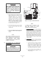
lNTRoD”C~oN:
THIS SAFEIY DATA SHEET APPUES TO WC3000 lNSlTU OXYGEN ANALYSER
(pROBE),MPE No. lUO5680.
THIS OXYGEN ANALYSER IS CERTlFlED EExd IIB 370 (Tl) :
ISSeP CERTlFlCATE No. 93C.103.1067.
THIS PIECE OF EQUIPMENT HAS BEEN DESIGNED AND MANUFACTURED TO OPERATE
SAFELY IN CERTAlN TYPES OF POTENTlALLY EXPLOSlVE ATMOSPHERES. lT Is ESSENTIAL
THAT THE EQUIPMENT IS NOT TAMPERED WITH OR DAMAGED IN ANY WAY WHICH
MIGHT LEAD TO A REDUCTlON IN lT’S ABIUTY TO OPERATE SAFELY IN SUCH POTENTlALLY
EXPLOSlVE ATMOSPHERES. FOR YOUR OWN SAFEIY AND THE =
OF OTHERS
PLEASE BRING ANY DAMAGE TO THE AlTENTlON OF THE RESPONSIBLE AUMORllY.
THIS PIECE OF EQUIPMENT HAS BEEN DESIGNED AND MANUFACTURED IN
ACCORDANCE WITH EUROPEAN STANDARDS EN50014 & EN5001 8. INSTALlAnON
MAINTENANCE AND REPAIR MUST BE IN ACCORDANCE WITH THE OFFlCAL “CODES
OF PRACTICE ON THE INSTAlATlON AND MAINTAINANCE OF ELECTRICAL APPARATUS
IN POTENTlALLY EXPLOSlVE ATMOSPHERES” FOR THE COUNljiY OF INSTALlATlON
(EXAMPLE: BS5345 IN GREAT BRlTAlN). ONLY APPROPRIATLY TRAINED PERSONNEL
ARE AUTHORISED TO PERFORM ANY ‘WORK ON THIS EQUIPMENT. SUCH PERSONNEL IN
ADDlTlON TO OPERATlNG TO THE ABOVE MENllONED SAFETY STANDARDS, SHOULD TAKE
NOTE OF THE FOLLOWING SAFElY ISSUES.
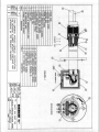
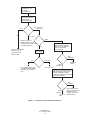
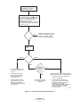
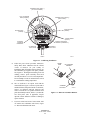
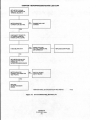
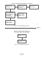
NOTE: THROUGHOUT THIS DATA SHEEl., CONTlNUOUS REFERENCE WILL BE MADE TO
FlGURE 1.
11)
POWER DOWN PROCEDURE:
ISOlATlON OF ELECTRICAL SUPPLY: THIS PIECE OF APPARATUS IS NOT lTSELF m
WlTH A MEANS OF ELECTRICAL ISOLP,nON. CONSULT YOUR LOCAL CODES OF PRACTlCE
ON THE INSTALLATION AND MAINTAINANCE OF ELECTRICAL APPARATUS IN POTENTIALLY
EXPLOSIVE ATMOSPHRES (BS5345 IN BRlTAIN) FOR INSTRUCTlON ON THE ISOlATlON OF
ELECTRICAL SUPPLY TO THE APPARATUS. FURTHER MORE THERE MUST BE “EFFECTIVE
MEASURES TO PREVENT THE RESTORATlON OF SUPPLY TO THE APPARATUS WHILE THE
RISK OF EXPOSING UNPROTECTED LIVE CONDUCTORS TO AN EXPLOSIVE ATMOSPHERE
CONTlNUES”:BS5345 PAPT 1 1989 S;ECTlON 18.
RESTORATlON OF SUPPLY FOR ELECTRICAL TESTING: “WHERE, FOR PURPOSES OF
ELECTRICAL TESTING. lT IS ESSENTIAL TO RESTORE THE SUPPLY BEFORE THE APPARATUS
IS RE-ASSEMBLED, MEN THIS WORK SHOULD BE UNDER A CONTROLLED PROCEDURE
AND .THE SPECIRC LOCATlON ASSESSED TO ENSURE THAT POTENTlALLY FLAMMABLE
GAS OR VAPOUR IS ABSENT”:BS5345 PART 1 1989 SECTlON 23.
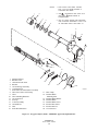
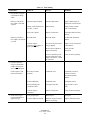
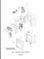
REMOVAL OF JUNCTlON BOX COVER: DO NOT REMOVE THE JUNCTlON BOX COVER
(lTEM 2) WHILE THE APPARATUS IS ENERGISED. DO NOT REMOVE THE JUNCTlON BOX
COVER WHEN A POTENTIALLY EXPLOSIVE ATMOSPHERE IS PRESENT. REMEMBER (ALTHOUGH
THE UNlT HAS BEEN POWERED DOWN AND THE PROBE HEATER HAS BEEN ALLOWED TO
COOL DOWN), THE TEMPERATURE ON THE INTERIOR OF THE PROBE TUBE (lTEM 1) WIU Bf
SlMllAR TO THE TEMPERATURE OF THE EXHAUST GAS. IF THERE IS A POTENTIALLY
EXPLOSIVE ATMOSPHERE IN THE REGION OF THE JUNCTlON BOX (lTEM 3). THIS GAS WlLL,
ON THE REMOVAL OF THE JUNCTlON BOX COVER BE EXPOSED TO THE HOT SURFACE OF
THE TUBE INTERIOR (lTEM 1).
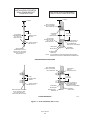
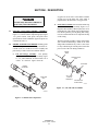
(2) THREADED JOINTS:
THE JOINT BEIWEEN THE JUNCTlON BOX @EM 3) AND THE
JUNCTlON BOX LID (lTEM 2) IS A THREADED JOINT. SO ALSO IS THE JOINT BElWEEN
THE PROBE END RANGE (lTEM 4) AND THE FLAME ARRESTOR HUB (lTEM 5). BOTH
THESE JOINTS ARE SECURED By SET SCREWS (ITEMS 6 & 7). BEFORE REMOVlNG
THE JUNCTlON BOX COVER (lTEM 2) OR THE RAME ARRESTOR HUB (lTEM 5). FULLY
REMOVE THE SET-SCREWS (ITEMS 6 h 7) FROM THEIR TAPPED HOLES. FAlLURE TO
DO THIS COULD RESULT IN DAMAGE TO. THE THREADS OF THE JUNCTION BOX (EM 3)
AND THE PROBE END FlANGE (lTEM 4) BY THE SET-SCREWS BEING DRAWN OVER
THE THREADS. REMEMBER WHEN REFlTllNG THE JUNCTION BOX LID AND THE FlAME
ARRESTOR HUB TO LOCK IN PLACE WITH THE SETSCREWS.
THE MATERIAL OF THE JUNCTlON BOX AND THE JUNCTION BOX UD IS ALUMINIUM
ALLOY. SPECIAL CARE SHOULD BE TAKEN TO AVOID DAMAGE TO THE THREADS.
NOTE THAT ROSEMOUNT SUPPLY ALLEN KEYS FOR REMOVAL & REPLACEMENT OF THE
SETSCREWS.
m
=A
05934
4-2-94
2
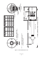
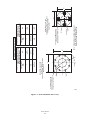
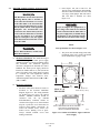
(3) CORROSION AND ABRASION:
0 PROBE TUBE (ITEM 1): TO PROVlDE RESISTANCE AGAlNST THE EFFECTS OF CORROSIOI
AND ABRASION JHE PROBE TUBE HAS BEEN MANUFACTURED FROM 4.75mm WALL,
316 SERIES STAINLESS STEEt FOR THE MAIORllY OF APPUCATlONS THE RESISTANCE
AFFORDED BY THIS PROBE TUBE AGAINST CORROSION AND ABRASION IS MORE
THAN ADEQUATE. FOR APPLlCAllONS IN WHilCH THE EFFECTS OF CORROSION
OR
ABRASION ARE SIGNIRCANT, ROSEMOUM’ CAN SUPPLY AN ABRASlVE SHIELD.
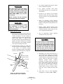
0 FIAME ARRESTOR HUB (ITEM 5):
THE FLAME ARRESTOR HUB HAS BEEN
MANUFACTURED FROM 316 SERIES STAINLESS STEEL. AT TrS THINNEST SECllON
(BETWEEN ME O/D OF THE HUB AND THE MAXIMUM MAJOR DIAMETER OF THE
M70 X 2 X 6H THREAD: SEE FIGURE 2). THE MINIMUM MATERlAL THICKNESS IS
2.75mm. FOR THE MAJORlIY OF APPLlCATlONS THE PROTECTlON AFFORDED BY
THIS ARRANGEMENT AGAlNST THE EFFECTS OF CORROSION AND ABRASION IS
MORE THAN ADEQUATE. FOR APPUCATlONS IN WHICH THE EFFECTS OF CORROSION
OR ABRASION ARE SIGNIFICANT. ROSEMOUNT CAN SUPPLY AN ABRASIVE SHIELD.
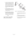
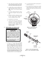
(4)
BREATHING DMCES:
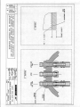
(5)
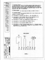
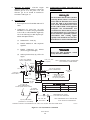
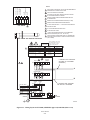
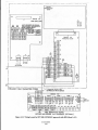
WlRlNG DIAGRAM:
EACH OF THE THREE BULKHEAD UNION FlTilNGS (ITEM 8)
HAS BEEN ~rrr~~ wmi A CAPILLARY ARRAY, (BREATHING DEVICE): SEE RGURE 3.
WHEN FlTllNG TUBING, (0.25 INCH O/D), TO THE REFERENCE AIR AND CALlBRATlON
GAS PORTS, TAKE CARE NOT TO DAMAGE THE BREATHING DEVICES. THE VENT PORT
SHOULD BE LEFT CLEAR OF OBSTRUCTIONS.
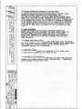
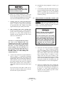
THE PROBE SHOULD BE WlRED As SHOWN IN flGURE 4.
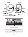
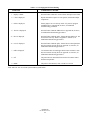
(6)
CUSTOMER REPAIRS:
THE FOLLOWlNG REPAIRS ARE THE ONLY REPAIRS WHICH THE
CUSTOMER IS ALLOWED TO _&&IKE:
0
REPLACEMENT OF ZIRCONIUM CELL (ITEM 9) -
0
REPLACEMENT OF STRUT ASSEMBLY @EM 10). THE RESISTANCE OF THE
REPLACEMENT HEATER MUST BE 11 OHMS OR GREATER
0
REPLACEMENT OF CONTACT AND THERMOCOUPLE ASSEMBLY (lTEM 11).
0
REPLACEMENT OF FlAME ARRESTOR HUB ASSEMBLY (lTEM 5).
0
REPLACEMENT OF VEE DEFLECTOR ASSEMBLY @EM 12).
.
REPLACEMENT OF CERAMIC DIFFUSION ELEMENT (lTEM 13) - DIFFUSION ELEMENT
REPLACEMENT KIT -. TAKE CARE NOT TO DAMAGE THE FLAME ARRESTOR (lTEM 18)
ITSELF OR THE FLAME ARRESTOR HUB.
J’lRING
CELL REPIACEMENT KlT -.
DIAGRAM
CELL
IYPE K
T/c
44v HTR
11 OHMS MIN.
13 OHMS MAX.
Y
3
05
m
FIGURE 4
(7)
CABLEENTRYZ
CABLE ENTRY TO MIS APPARTUS IS VIA THE l/2’*
NPT CABLE
-, ENTRY PORT PROVlD!
.__3.J. ME CABLE ENTRY MUST M wmu~ THE RAMEPRooF
THE
PROPERTlES OF ‘_.
__ ENCLOSlIRE.
__
ROSEMOUNT CAN Sup ‘PLY A CABLE WHICH
IS TERMINATE0 WlTH A
(STOPPER) GLAND. A FEATURE OF THlS GlAND
FORMS A BARRIER
ISS$MF’PUND
1 RLLED PACKING MATEIRW, (PUllY),
DMDUAL INSUIAED CONDUCTORS‘ OF THE CABLE. THIS
BARRIER ACTS TO PRI?/ENT ENTRY INTO THE CABLf: OF THE PRODUCTS OF
THE GIANC1 IS CERTlflEO Exd IIC.
AN EXPLOSION WllHlN THE plCtOSURE.
.._----..--
WARNING; ON EARUER VERSIONS OF THE ABOVE CABLE SUPPLIED BY
WESTlNGH0USE/R0SEM0UNT;‘E:
GLANDS. ALTHOUGH CERTlflED Exd EC,
WERE NOT OF THE BARRIER GLAND -lYPE. THIS GIAND SHOULD NOT BE USED
WITH THE WC3000 INSlTU OXYGEN ANALYSER.ROSEMOUNT CAN SUPPLY A
BARRIER GLAND KCf TO REPLACE: SUCH GLANDS. THE KFT (P/N lUO3066GG7).
COMPRISES OF TWO BARRIER GLANDS COMPLEIE WITH Pm,
CRIMPS AND
AN IN!5TRUCTlON SHEET. PLE4SE NOTE THAT YOU SHOULD USE ONLY PUTlY
WHICH IS PLAsnC AND CAPABLE OF BUNG MIXED. YOU SHOULD NOT USE
CRYSTALlSED OR HARD PUITY.
ANCHQRAGF,
THE PROBE JUNAON
BOX DOES NOT INCLUDE ANY SPECIRC MEANS FOR
CABLE ANCHORAGE. THE CABLE GLAND CHOSEN MUST BE ONE WHICH PROVIDE!
CABLE ANCHORAGE. THE BARRIER (STOPPER) GLAND SUPPUED BY ROSEMOUM
AS PART OF THE PROBE CABLE ASSEMBLY, WILL PROVIDE CABLE ANCHORAGE.
(6)
(9)
i~mwcznoN
BUUNS
(USER MANUALS):
DEPENDING ON THE ELECTRONICS CONTROL UNlT USED, THE APPUCABLE
INSTRUCTION BULLEllNS ARE AS FOLLOM:
IB-106-300NM
: USED IN THE ‘*EXCHANGE PROBE” CONFlGURATlON
AND IN THE “FULLY CENELEC CERTIFIED” CONFIGURATION
: USED WITH IFT3000 ELECTRONICS.
18-l 06-300NFX
IB-106-300NCX
: USED WITH CRE3000 ELECTRONICS.
THESE INSTRUCTlON BUUETlNS CONTAlN ESSENTIAL INFORMATION AND MUST
BE USED WHEN WORKING ON MIE APPARATUS.
(10)
NAMEPLATE (LABEL):
ENSURE THAT NAMEPLATE (lTEM 15) IS AT ALL TlMES
VISIBLE. AT INSTALIATION, ALLOWANCE MUST BE MADE FOR THIS.
(11)
EARTHING OF THE APPARATUS:.
THE APPARATUS HAS BEEN FilTED WKH
BOTH f!XTERNAL (tTEM 16) AND INTERNAL (lTEM 17) EAR-IHING POINFS.
ADEQUATE EARTH CONNECTIONS SHOULD BE MADE TO BOTH THESE POINTS.
0 2)
MATCHING OF JUNaON
BOX UD WlTH JUNCTlON BOX :
THE JUNCTION UD AND THE JUNCllON BOX ARE A MATCHED PAlR WHEN
FULLY SCREWED ON, THE SRSCREW THREADED HOLE ON THE UD UNES
UP Wrm AN UNDERCUT AT THE BOlTOM OF THE JUNCTlON BOX. ME
SEISCREW ENGAGES INTO THIS IJNDERCtTT. IF YOU HAVE A NUMBER OF
PROBES, THEN TAKE-CARE TO KEEP THE UD AND PROBE MATCHED.
(13)
LlmNG & CARRYING:
BOTH THE PROBE AND ABRASIVE SHIM
ARE HEAVY PIECES OF EpuIPMENT.
LlFllNG AND CARRYlNG PROCEDURES SHOULD TAKE ACCOUNT OF THIS
WEIGHT.
DE0
05934
4-2-94
2
~““““““““““‘““““‘“‘“‘--“---------------””””””~”““““““““““”””””””““““““““““““““““““““““““““”””””,
t
t
I
I
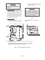
HIGHLIGHTS OF CHANGES
Effective June, 1997 Rev. 4
PAGE
--
SUMMARY
General. Added snubber version of probe to manual. Text and art changed as necessary to reflect new
style of probe.
Effective February, 1998 Rev. 4.1
PAGE
SUMMARY
2-2
Figure 2-1. Change calibration gas tube dimensions.
3-10
Add note on test gas flowmeter.
IB-106-300NFX
ROSEMOUNT WARRANTY
Rosemount warrants that the equipment manufactured and sold by it will, upon shipment, be free of defects
in workmanship or material. Should any failure to conform to this warranty become apparent during a period of
one year after the date of shipment, Rosemount shall, upon prompt written notice from the purchaser, correct such
nonconformity by repair or replacement, F.O.B. factory of the defective part or parts. Correction in the manner
provided above shall constitute a fulfillment of all liabilities of Rosemount with respect to the quality of the
equipment.
THE FOREGOING WARRANTY IS EXCLUSIVE AND IN LIEU OF ALL OTHER
WARRANTIES OF QUALITY WHETHER WRITTEN, ORAL, OR IMPLIED (INCLUDING ANY
WARRANTY OF MERCHANTABILITY OF FITNESS FOR PURPOSE).
The remedy(ies) provided above shall be purchaser's sole remedy(ies) for any failure of Rosemount to comply
with the warranty provisions, whether claims by the purchaser are based in contract or in tort (including
negligence).
Rosemount does not warrant equipment against normal deterioration due to environment. Factors such as
corrosive gases and solid particulates can be detrimental and can create the need for repair or replacement as part
of normal wear and tear during the warranty period.
Equipment supplied by Rosemount Analytical Inc., but not manufactured by it, will be subject to the same
warranty as is extended to Rosemount by the original manufacturer.
At the time of installation, it is important that the required services are supplied to the system and that the
electronic controller is set up at least to the point where it is controlling the sensor heater. This will ensure that
should there be a delay between installation and full commissioning, the sensor being supplied with ac power and
reference air will not be subjected to component deterioration.
IB-106-300NFX
i
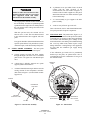
PURPOSE
The purpose of this manual is to provide a comprehensive understanding of the CENELEC Approved
World Class 3000 Oxygen Analyzer components, functions, installation, and maintenance.
This manual is designed to provide information about the CENELEC Approved World Class 3000 Oxygen
Analyzer. We recommend that you thoroughly familiarize yourself with the Overview and Installation sections
before installing your emissions monitor.
The overview presents the basic principles of the CENELEC oxygen analyzer along with its performance
characteristics and components. The remaining sections contain detailed procedures and information necessary
to install and service the CENELEC approved oxygen analyzer.
Before contacting Rosemount concerning any questions, first consult this manual. It describes most
situations encountered in your equipment's operation and details necessary action.
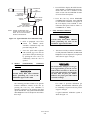
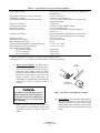
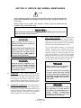
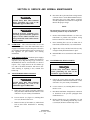
DEFINITIONS
The following definitions apply to WARNINGS, CAUTIONS, and NOTES found throughout this
publication.
Highlights an operation or maintenance
procedure, practice, condition,
statement, etc., that if not strictly
observed, could result in injury, death,
or long-term health hazards of
personnel.
Highlights an operation or maintenance
procedure, practice, condition,
statement, etc., that if not strictly
observed, could result in damage to or
destruction of equipment, or loss of
effectiveness.
NOTE
Highlights an essential operating procedure,
condition, or statement.
: EARTH (GROUND) TERMINAL
: PROTECTIVE CONDUCTOR TERMINAL
: RISK OF ELECTRICAL SHOCK
: WARNING: REFER TO INSTRUCTION BULLETIN
NOTE TO USERS
The number in the lower right corner of each illustration in this publication is a manual
illustration number. It is not a part number and is not related to the illustration in any
technical manner.
IB-106-300NFX
ii
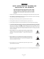
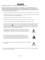
IMPORTANT
SAFETY INSTRUCTIONS FOR THE WIRING AND
INSTALLATION OF THIS APPARATUS
The following safety instructions apply specifically to all EU member
states. They should be strictly adhered to in order to assure
compliance with the Low Voltage Directive. Non-EU states should
also comply with the following unless superseded by local or National
Standards.
1. Adequate earth connections should be made to all earthing points, internal and external, where provided.
2. After installation or troubleshooting, all safety covers and safety grounds must be replaced. The integrity
of all earth terminals must be maintained at all times.
3. Mains supply cords should comply with the requirements of IEC227 or IEC245.
4. All wiring shall be suitable for use in an ambient temperature of greater than 75°C.
5. All cable glands used should be of such internal dimensions as to provide adequate cable anchorage.
6. To ensure safe operation of this equipment, connection to the mains supply should only be made through
a circuit breaker which will disconnect all circuits carrying conductors during a fault situation. The circuit
breaker may also include a mechanically operated isolating switch. If not, then another means of
disconnecting the equipment from the supply must be provided and clearly marked as such. Circuit
breakers or switches must comply with a recognized standard such as IEC947. All wiring must conform
with any local standards.
7. Where equipment or covers are marked with the symbol to the right, hazardous
voltages are likely to be present beneath. These covers should only be removed
when power is removed from the equipment — and then only by trained service
personnel.
8. Where equipment or covers are marked with the symbol to the right, there is a
danger from hot surfaces beneath. These covers should only be removed by
trained service personnel when power is removed from the equipment. Certain
surfaces may remain hot to the touch.
9. Where equipment or covers are marked with the symbol to the right, refer to the
Operator Manual for instructions.
10. All graphical symbols used in this product are from one or more of the following standards: EN61010-1,
IEC417, and ISO3864.
IB-106-300NFX
iii
BELANGRIJK
Veiligheidsvoorschriften voor de aansluiting en installatie van dit toestel.
De hierna volgende veiligheidsvoorschriften zijn vooral bedoeld voor de EU lidstaten. Hier moet aan
gehouden worden om de onderworpenheid aan de Laag Spannings Richtlijn (Low Voltage Directive) te
verzekeren. Niet EU staten zouden deze richtlijnen moeten volgen tenzij zij reeds achterhaald zouden zijn
door plaatselijke of nationale voorschriften.
1.
Degelijke aardingsaansluitingen moeten gemaakt worden naar alle voorziene aardpunten, intern en extern.
2.
Na installatie of controle moeten alle veiligheidsdeksels en -aardingen terug geplaatst worden. Ten alle tijde
moet de betrouwbaarheid van de aarding behouden blijven.
3.
Voedingskabels moeten onderworpen zijn aan de IEC227 of de IEC245 voorschriften.
4.
Alle bekabeling moet geschikt zijn voor het gebruik in omgevingstemperaturen, hoger dan 75°C.
5.
Alle wartels moeten zo gedimensioneerd zijn dat een degelijke kabel bevestiging verzekerd is.
6.
Om de veilige werking van dit toestel te verzekeren, moet de voeding door een stroomonderbreker gevoerd
worden (min 10A) welke alle draden van de voeding moet onderbreken. De stroomonderbreker mag een
mechanische schakelaar bevatten. Zoniet moet een andere mogelijkheid bestaan om de voedingsspanning
van het toestel te halen en ook duidelijk zo zijn aangegeven. Stroomonderbrekers of schakelaars moeten
onderworpen zijn aan een erkende standaard zoals IEC947.
7.
Waar toestellen of deksels aangegeven staan met het symbool is er meestal
hoogspanning aanwezig. Deze deksels mogen enkel verwijderd worden nadat de
voedingsspanning werd afgelegd en enkel door getraind onderhoudspersoneel.
8.
Waar toestellen of deksels aangegeven staan met het symbool is er gevaar
voor hete oppervlakken. Deze deksels mogen enkel verwijderd worden door
getraind onderhoudspersoneel nadat de voedingsspanning verwijderd werd.
Sommige oppper-vlakken kunnen 45 minuten later nog steeds heet aanvoelen.
9.
Waar toestellen of deksels aangegeven staan met het symbool gelieve het handboek
te raadplegen.
10. Alle grafische symbolen gebruikt in dit produkt, zijn afkomstig uit een of meer van devolgende standaards;
EN61010-1, IEC417 en ISO3864.
IB-106-300NFX
iv
VIGTIGT
Sikkerhedsinstruktion for tilslutning og installering af dette udstyr.
Følgende sikkerhedsinstruktioner gælder specifikt i alle EU-medlemslande. Instruktionerne skal nøje
følges for overholdelse af Lavsspændingsdirektivet og bør også følges i ikke EU-lande medmindre andet er
specificeret af lokale eller nationale standarder.
1.
Passende jordforbindelser skal tilsluttes alle jordklemmer, interne og eksterne, hvor disse forefindes.
2.
Efter installation eller fejlfinding skal alle sikkerhedsdæksler og jordforbindelser reetableres.
3.
Forsyningskabler skal opfylde krav specificeret i IEC227 eller IEC245.
4.
Alle ledningstilslutninger skal være konstrueret til omgivelsestemperatur højere end 75° C.
5.
Alle benyttede kabelforskruninger skal have en intern dimension, så passende kabelaflastning kan etableres.
6.
For opnåelse af sikker drift og betjening skal der skabes beskyttelse mod indirekte berøring gennem afbryder
(min. 10A), som vil afbryde alle kredsløb med elektriske ledere i fejlsitua-tion. Afbryderen skal indholde en
mekanisk betjent kontakt. Hvis ikke skal anden form for afbryder mellem forsyning og udstyr benyttes og
mærkes som sådan. Afbrydere eller kontakter skal overholde en kendt standard som IEC947.
7.
Hvor udstyr eller dæksler er mærket med dette symbol, er farlige
spændinger normalt forekom-mende bagved. Disse dæksler bør kun
afmonteres, når forsyningsspændingen er frakoblet - og da kun af
instrueret servicepersonale.
8.
Hvor udstyr eller dæksler er mærket med dette symbol, forefindes
meget varme overflader bagved. Disse dæksler bør kun afmonteres af
instrueret servicepersonale, når forsyningsspænding er frakoblet. Visse
overflader vil stadig være for varme at berøre i op til 45 minutter efter
frakobling.
9.
Hvor udstyr eller dæksler er mærket med dette symbol, se da i
betjeningsmanual for instruktion.
10. Alle benyttede grafiske symboler i dette udstyr findes i én eller flere af følgende standarder:- EN61010-1,
IEC417 & ISO3864.
IB-106-300NFX
v
BELANGRIJK
Veiligheidsinstructies voor de bedrading en installatie van dit apparaat.
Voor alle EU lidstaten zijn de volgende veiligheidsinstructies van toepassing. Om aan de geldende
richtlijnen voor laagspanning te voldoen dient men zich hieraan strikt te houden. Ook niet EU lidstaten
dienen zich aan het volgende te houden, tenzij de lokale wetgeving anders voorschrijft.
1.
Alle voorziene interne- en externe aardaansluitingen dienen op adequate wijze aangesloten te worden.
2.
Na installatie,onderhouds- of reparatie werkzaamheden dienen alle beschermdeksels /kappen en aardingen
om reden van veiligheid weer aangebracht te worden.
3.
Voedingskabels dienen te voldoen aan de vereisten van de normen IEC 227 of IEC 245.
4.
Alle bedrading dient geschikt te zijn voor gebruik bij een omgevings temperatuur boven 75°C.
5.
Alle gebruikte kabelwartels dienen dusdanige inwendige afmetingen te hebben dat een adequate verankering
van de kabel wordt verkregen.
6.
Om een veilige werking van de apparatuur te waarborgen dient de voeding uitsluitend plaats te vinden via
een meerpolige automatische zekering (min.10A) die alle spanningvoerende geleiders verbreekt indien een
foutconditie optreedt. Deze automatische zekering mag ook voorzien zijn van een mechanisch bediende
schakelaar. Bij het ontbreken van deze voorziening dient een andere als zodanig duidelijk aangegeven
mogelijkheid aanwezig te zijn om de spanning van de apparatuur af te schakelen. Zekeringen en schakelaars
dienen te voldoen aan een erkende standaard zoals IEC 947.
7.
Waar de apparatuur of de beschermdeksels/kappen gemarkeerd zijn met het
volgende symbool, kunnen zich hieronder spanning voerende delen bevinden die
gevaar op kunnen leveren. Deze beschermdeksels/kappen mogen uitsluitend
verwijderd worden door getraind personeel als de spanning is afgeschakeld.
8.
Waar de apparatuur of de beschermdeksels/kappen gemarkeerd zijn met het
volgende symbool, kunnen zich hieronder hete oppervlakken of onderdelen
bevinden. Bepaalde delen kunnen mogelijk na 45 min. nog te heet zijn om aan te
raken.
9.
Waar de apparatuur of de beschermdeksels/kappen gemarkeerd zijn met het
volgende symbool, dient men de bedieningshandleiding te raadplegen.
10. Alle grafische symbolen gebruikt bij dit produkt zijn volgens een of meer van de volgende standaarden:
EN 61010-1, IEC 417 & ISO 3864.
IB-106-300NFX
vi
TÄRKEÄÄ
Turvallisuusohje, jota on noudatettava tämän laitteen asentamisessa ja kaapeloinnissa.
Seuraavat ohjeet pätevät erityisesti EU:n jäsenvaltioissa. Niitä täytyy ehdottomasti noudattaa jotta
täytettäisiin EU:n matalajännitedirektiivin (Low Voltage Directive) yhteensopivuus. Myös EU:hun
kuulumattomien valtioiden tulee nou-dattaa tätä ohjetta, elleivät kansalliset standardit estä sitä.
1.
Riittävät maadoituskytkennät on tehtävä kaikkiin maadoituspisteisiin, sisäisiin ja ulkoisiin.
2.
Asennuksen ja vianetsinnän jälkeen on kaikki suojat ja suojamaat asennettava takaisin pai-koilleen.
Maadoitusliittimen kunnollinen toiminta täytyy aina ylläpitää.
3.
Jännitesyöttöjohtimien täytyy täyttää IEC227 ja IEC245 vaatimukset.
4.
Kaikkien johdotuksien tulee toimia >75°C lämpötiloissa.
5.
Kaikkien läpivientiholkkien sisähalkaisijan täytyy olla sellainen että kaapeli lukkiutuu kun-nolla kiinni.
6.
Turvallisen toiminnan varmistamiseksi täytyy jännitesyöttö varustaa turvakytkimellä (min 10A), joka kytkee
irti kaikki jännitesyöttöjohtimet vikatilanteessa. Suojaan täytyy myös sisältyä mekaaninen erotuskytkin. Jos
ei, niin jännitesyöttö on pystyttävä katkaisemaan muilla keinoilla ja merkittävä siten että se tunnistetaan
sellaiseksi. Turvakytkimien tai kat-kaisimien täytyy täyttää IEC947 standardin vaatimukset näkyvyydestä.
7.
Mikäli laite tai kosketussuoja on merkitty tällä merkillä on merkinnän takana tai alla
hengenvaarallisen suuruinen jännite. Suojaa ei saa poistaa jänniteen ollessa kytkettynä
laitteeseen ja poistamisen saa suorittaa vain alan asian-tuntija.
8.
Mikäli laite tai kosketussuoja on merkitty tällä merkillä on merkinnän takana tai alla
kuuma pinta. Suojan saa poistaa vain alan asiantuntija kun jännite-syöttö on katkaistu.
Tällainen pinta voi säilyä kosketuskuumana jopa 45 mi-nuuttia.
9.
Mikäli laite tai kosketussuoja on merkitty tällä merkillä katso lisäohjeita käyttöohjekirjasta
10. Kaikki tässä tuotteessa käytetyt graafiset symbolit ovat yhdestä tai useammasta seuraavis-ta standardeista:
EN61010-1, IEC417 & ISO3864.
IB-106-300NFX
vii
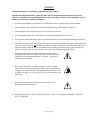
IMPORTANT
Consignes de sécurité concernant le raccordement et l’installation de cet appareil.
Les consignes de sécurité ci-dessous s’adressent particulièrement à tous les états membres de la
communauté européenne. Elles doivent être strictement appliquées afin de satisfaire aux directives
concernant la basse tension. Les états non membres de la communauté européenne doivent également
appliquer ces consignes sauf si elles sont en contradiction avec les standards locaux ou nationaux.
1.
Un raccordement adéquate à la terre doit être effectuée à chaque borne de mise à la terre, interne et externe.
2.
Après installation ou dépannage, tous les capots de protection et toutes les prises de terre doivent être remis
en place, toutes les prises de terre doivent être respectées en permanence.
3.
Les câbles d’alimentation électrique doivent être conformes aux normes IEC227 ou IEC245
4.
Tous les raccordements doivent pouvoir supporter une température ambiante supérieure à 75°C.
5.
Tous les presse-étoupes utilisés doivent avoir un diamètre interne en rapport avec les câbles afin d’assurer
un serrage correct sur ces derniers.
6.
Afin de garantir la sécurité du fonctionnement de cet appareil, le raccordement à l’alimentation électrique
doit être réalisé exclusivement au travers d’un disjoncteur (minimum 10A.) isolant tous les conducteurs en
cas d’anomalie. Ce disjoncteur doit également pouvoir être actionné manuellement, de façon mécanique.
Dans le cas contraire, un autre système doit être mis en place afin de pouvoir isoler l’appareil et doit être
signalisé comme tel. Disjoncteurs et interrupteurs doivent être conformes à une norme reconnue telle
IEC947.
7.
Lorsque les équipements ou les capots affichent le symbole suivant, cela signifie que des tensions
dangereuses sont présentes. Ces capots ne doivent être démontés que lorsque l’alimentation est
coupée, et uniquement par un personnel compétent.
8.
Lorsque les équipements ou les capots affichent le symbole suivant, cela signifie que des surfaces
dangereusement chaudes sont présentes. Ces capots ne doivent être démontés que lorsque
l’alimentation est coupée, et uniquement par un personnel compétent. Certaines surfaces peuvent
rester chaudes jusqu’à 45 mn.
9.
Lorsque les équipements ou les capots affichent le symbole suivant, se reporter au manuel
d’instructions.
10. Tous les symboles graphiques utilisés dans ce produit sont conformes à un ou plusieurs des standards
suivants: EN61010-1, IEC417 & ISO3864.
IB-106-300NFX
viii
Wichtig
Sicherheitshinweise für den Anschluß und die Installation dieser Geräte.
Die folgenden Sicherheitshinweise sind in allen Mitgliederstaaten der europäischen Gemeinschaft gültig.
Sie müssen strickt eingehalten werden, um der Niederspannungsrichtlinie zu genügen.
Nichtmitgliedsstaaten der europäischen Gemeinschaft sollten die national gültigen Normen und
Richtlinien einhalten.
1.
Alle intern und extern vorgesehenen Erdungen der Geräte müssen ausgeführt werden.
2.
Nach Installation, Reparatur oder sonstigen Eingriffen in das Gerät müssen alle Sicherheitsabdeckungen und
Erdungen wieder installiert werden. Die Funktion aller Erdverbindungen darf zu keinem Zeitpunkt gestört
sein.
3.
Die Netzspannungsversorgung muß den Anforderungen der IEC227 oder IEC245 genügen.
4.
Alle Verdrahtungen sollten mindestens bis 75 °C ihre Funktion dauerhaft erfüllen.
5.
Alle Kabeldurchführungen und Kabelverschraubungen sollten in Ihrer Dimensionierung so gewählt werden,
daß diese eine sichere Verkabelung des Gerätes ermöglichen.
6.
Um eine sichere Funktion des Gerätes zu gewährleisten, muß die Spannungsversorgung über mindestens 10
A abgesichert sein. Im Fehlerfall muß dadurch gewährleistet sein, daß die Spannungsversorgung zum Gerät
bzw. zu den Geräten unterbrochen wird. Ein mechanischer Schutzschalter kann in dieses System integriert
werden. Falls eine derartige Vorrichtung nicht vorhanden ist, muß eine andere Möglichkeit zur
Unterbrechung der Spannungszufuhr gewährleistet werden mit Hinweisen deutlich gekennzeichnet werden.
Ein solcher Mechanismus zur Spannungsunterbrechung muß mit den Normen und Richtlinien für die
allgemeine Installation von Elektrogeräten, wie zum Beispiel der IEC947, übereinstimmen.
7.
Mit dem Symbol sind Geräte oder Abdeckungen gekennzeichnet, die eine gefährliche
(Netzspannung) Spannung führen. Die Abdeckungen dürfen nur entfernt werden,
wenn die Versorgungsspannung unterbrochen wurde. Nur geschultes Personal darf an
diesen Geräten Arbeiten ausführen.
8.
Mit dem Symbol sind Geräte oder Abdeckungen gekennzeichnet, in bzw. unter denen
heiße Teile vorhanden sind. Die Abdeckungen dürfen nur entfernt werden, wenn die
Versorgungsspannung unterbrochen wurde. Nur geschultes Personal darf an diesen
Geräten Arbeiten ausführen. Bis 45 Minuten nach dem Unterbrechen der Netzzufuhr
können derartig Teile noch über eine erhöhte Temperatur verfügen.
9.
Mit dem Symbol sind Geräte oder Abdeckungen gekennzeichnet, bei denen vor dem
Eingriff die entsprechenden Kapitel im Handbuch sorgfältig durchgelesen werden
müssen.
10. Alle in diesem Gerät verwendeten graphischen Symbole entspringen einem oder mehreren der nachfolgend
aufgeführten Standards: EN61010-1, IEC417 & ISO3864.
IB-106-300NFX
ix
IMPORTANTE
Norme di sicurezza per il cablaggio e l’installazione dello strumento.
Le seguenti norme di sicurezza si applicano specificatamente agli stati membri dell’Unione Europea, la cui
stretta osservanza è richiesta per garantire conformità alla Direttiva del Basso Voltaggio. Esse si applicano
anche agli stati non appartenenti all’Unione Europea, salvo quanto disposto dalle vigenti normative locali
o nazionali.
1.
Collegamenti di terra idonei devono essere eseguiti per tutti i punti di messa a terra interni ed esterni, dove
previsti.
2.
Dopo l’installazione o la localizzazione dei guasti, assicurarsi che tutti i coperchi di protezione siano stati
collocati e le messa a terra siano collegate. L’integrità di ciscun morsetto di terra deve essere costantemente
garantita.
3.
I cavi di alimentazione della rete devono essere secondo disposizioni IEC227 o IEC245.
4.
L’intero impianto elettrico deve essere adatto per uso in ambiente con temperature superiore a 75°C.
5.
Le dimensioni di tutti i connettori dei cavi utilizzati devono essere tali da consentire un adeguato ancoraggio
al cavo.
6.
Per garantire un sicuro funzionamento dello strumento il collegamento alla rete di alimentazione principale
dovrà essere eseguita tramite interruttore automatico (min.10A), in grado di disattivare tutti i conduttori di
circuito in caso di guasto. Tale interruttore dovrà inoltre prevedere un sezionatore manuale o altro
dispositivo di interruzione dell’alimentazione, chiaramente identificabile. Gli interruttori dovranno essere
conformi agli standard riconosciuti, quali IEC947.
7.
Il simbolo riportato sullo strumento o sui coperchi di protezione indica probabile presenza di
elevati voltaggi. Tali coperchi di protezione devono essere rimossi esclusivamente da personale
qualificato, dopo aver tolto alimentazione allo strumento.
8.
Il simbolo riportato sullo strumento o sui coperchi di protezione indica rischio di contatto con
superfici ad alta temperatura. Tali coperchi di protezione devono essere rimossi esclusivamente da
personale qualificato, dopo aver tolto alimentazione allo strumento. Alcune superfici possono
mantenere temperature elevate per oltre 45 minuti.
9.
Se lo strumento o il coperchio di protezione riportano il simbolo, fare
riferimento alle istruzioni del manuale Operatore.
10. Tutti i simboli grafici utilizzati in questo prodotto sono previsti da uno o più dei seguenti standard:
EN61010-1, IEC417 e ISO3864.
IB-106-300NFX
x
VIKTIG
Sikkerhetsinstruks for tilkobling og installasjon av dette utstyret.
Følgende sikkerhetsinstruksjoner gjelder spesifikt alle EU medlemsland og land med i EØS-avtalen.
Instruksjonene skal følges nøye slik at installasjonen blir i henhold til lavspenningsdirektivet. Den bør
også følges i andre land, med mindre annet er spesifisert av lokale- eller nasjonale standarder.
1.
Passende jordforbindelser må tilkobles alle jordingspunkter, interne og eksterne hvor disse forefinnes.
2.
Etter installasjon eller feilsøking skal alle sikkerhetsdeksler og jordforbindelser reetableres.
Jordingsforbindelsene må alltid holdes i god stand.
3.
Kabler fra spenningsforsyning skal oppfylle kravene spesifisert i IEC227 eller IEC245.
4.
Alle ledningsforbindelser skal være konstruert for en omgivelsestemperatur høyere en 750C.
5.
Alle kabelforskruvninger som benyttes skal ha en indre dimensjon slik at tilstrekkelig avlastning oppnåes.
6.
For å oppnå sikker drift og betjening skal forbindelsen til spenningsforsyningen bare skje gjennom en
strømbryter (minimum 10A) som vil bryte spenningsforsyningen til alle elektriske kretser ved en
feilsituasjon. Strømbryteren kan også inneholde en mekanisk operert bryter for å isolere instrumentet fra
spenningsforsyningen. Dersom det ikke er en mekanisk operert bryter installert, må det være en annen måte
å isolere utstyret fra spenningsforsyningen, og denne måten må være tydelig merket. Kretsbrytere eller
kontakter skal oppfylle kravene i en annerkjent standard av typen IEC947 eller tilsvarende.
7.
Der hvor utstyr eller deksler er merket med symbol for farlig spenning, er det
sannsynlig at disse er tilstede bak dekslet. Disse dekslene må bare fjærnes når
spenningsforsyning er frakoblet utstyret, og da bare av trenet servicepersonell.
8.
Der hvor utstyr eller deksler er merket med symbol for meget varm overflate, er det
sannsynlig at disse er tilstede bak dekslet. Disse dekslene må bare fjærnes når
spenningsforsyning er frakoblet utstyret, og da bare av trenet servicepersonell. Noen
overflater kan være for varme til å berøres i opp til 45 minutter etter
spenningsforsyning frakoblet.
9.
Der hvor utstyret eller deksler er merket med symbol, vennligst referer til
instruksjonsmanualen for instrukser.
10. Alle grafiske symboler brukt i dette produktet er fra en eller flere av følgende standarder: EN61010-1,
IEC417 & ISO3864.
IB-106-300NFX
xi
IMPORTANTE
Instruções de segurança para ligação e instalação deste aparelho.
As seguintes instruções de segurança aplicam-se especificamente a todos os estados membros da UE.
Devem ser observadas rigidamente por forma a garantir o cumprimento da Directiva sobre Baixa Tensão.
Relativamente aos estados que não pertençam à UE, deverão cumprir igualmente a referida directiva,
exceptuando os casos em que a legislação local a tiver substituído.
1.
Devem ser feitas ligações de terra apropriadas a todos os pontos de terra, internos ou externos.
2.
Após a instalação ou eventual reparação, devem ser recolocadas todas as tampas de segurança e terras de
protecção. Deve manter-se sempre a integridade de todos os terminais de terra.
3.
Os cabos de alimentação eléctrica devem obedecer às exigências das normas IEC227 ou IEC245.
4.
Os cabos e fios utilizados nas ligações eléctricas devem ser adequados para utilização a uma temperatura
ambiente até 75º C.
5.
As dimensões internas dos bucins dos cabos devem ser adequadas a uma boa fixação dos cabos.
6.
Para assegurar um funcionamento seguro deste equipamento, a ligação ao cabo de alimentação eléctrica
deve ser feita através de um disjuntor (min. 10A) que desligará todos os condutores de circuitos durante uma
avaria. O disjuntor poderá também conter um interruptor de isolamento accionado manualmente. Caso
contrário, deverá ser instalado qualquer outro meio para desligar o equipamento da energia eléctrica,
devendo ser assinalado convenientemente. Os disjuntores ou interruptores devem obedecer a uma norma
reconhecida, tipo IEC947.
7.
Sempre que o equipamento ou as tampas contiverem o símbolo, é provável a existência de tensões
perigosas. Estas tampas só devem ser retiradas quando a energia eléctrica tiver sido desligada e
por Pessoal da Assistência devidamente treinado.
8.
Sempre que o equipamento ou as tampas contiverem o símbolo, há perigo de existência de
superfícies quentes. Estas tampas só devem ser retiradas por Pessoal da Assistência devidamente
treinado e depois de a energia eléctrica ter sido desligada. Algumas superfícies permanecem
quentes até 45 minutos depois.
9.
Sempre que o equipamento ou as tampas contiverem o símbolo, o Manual de Funcionamento deve
ser consultado para obtenção das necessárias instruções.
10. Todos os símbolos gráficos utilizados neste produto baseiam-se em uma ou mais das seguintes normas:
EN61010-1, IEC417 e ISO3864.
IB-106-300NFX
xii
IMPORTANTE
Instrucciones de seguridad para el montaje y cableado de este aparato.
Las siguientes instrucciones de seguridad , son de aplicacion especifica a todos los miembros de la UE y se
adjuntaran para cumplir la normativa europea de baja tension.
1.
Se deben preveer conexiones a tierra del equipo, tanto externa como internamente, en aquellos terminales
previstos al efecto.
2.
Una vez finalizada las operaciones de mantenimiento del equipo, se deben volver a colocar las cubiertas de
seguridad aasi como los terminales de tierra. Se debe comprobar la integridad de cada terminal.
3.
Los cables de alimentacion electrica cumpliran con las normas IEC 227 o IEC 245.
4.
Todo el cableado sera adecuado para una temperatura ambiental de 75ºC.
5.
Todos los prensaestopas seran adecuados para una fijacion adecuada de los cables.
6.
Para un manejo seguro del equipo, la alimentacion electrica se realizara a traves de un interruptor
magnetotermico ( min 10 A ), el cual desconectara la alimentacion electrica al equipo en todas sus fases
durante un fallo. Los interruptores estaran de acuerdo a la norma IEC 947 u otra de reconocido prestigio.
7.
Cuando las tapas o el equipo lleve impreso el simbolo de tension electrica peligrosa,
dicho alojamiento solamente se abrira una vez que se haya interrumpido la
alimentacion electrica al equipo asimismo la intervencion sera llevada a cabo por
personal entrenado para estas labores.
8.
Cuando las tapas o el equipo lleve impreso el simbolo, hay superficies con alta
temperatura, por tanto se abrira una vez que se haya interrumpido la alimentacion
electrica al equipo por personal entrenado para estas labores, y al menos se esperara
unos 45 minutos para enfriar las superficies calientes.
9.
Cuando el equipo o la tapa lleve impreso el simbolo, se consultara el manual de
instrucciones.
10. Todos los simbolos graficos usados en esta hoja, estan de acuerdo a las siguientes normas EN61010-1,
IEC417 & ISO 3864.
IB-106-300NFX
xiii
VIKTIGT
Säkerhetsföreskrifter för kablage och installation av denna apparat.
Följande säkerhetsföreskrifter är tillämpliga för samtliga EU-medlemsländer. De skall följas i varje
avseende för att överensstämma med Lågspännings direktivet. Icke EU medlemsländer skall också följa
nedanstående punkter, såvida de inte övergrips av lokala eller nationella föreskrifter.
1.
Tillämplig jordkontakt skall utföras till alla jordade punkter, såväl internt som externt där så erfordras.
2.
Efter installation eller felsökning skall samtliga säkerhetshöljen och säkerhetsjord återplaceras. Samtliga
jordterminaler måste hållas obrutna hela tiden.
3.
Matningsspänningens kabel måste överensstämma med föreskrifterna i IEC227 eller IEC245.
4.
Allt kablage skall vara lämpligt för användning i en omgivningstemperatur högre än 75ºC.
5.
Alla kabelförskruvningar som används skall ha inre dimensioner som motsvarar adekvat kabelförankring.
6.
För att säkerställa säker drift av denna utrustning skall anslutning till huvudströmmen endast göras genom
en säkring (min 10A) som skall frånkoppla alla strömförande kretsar när något fel uppstår. Säkringen kan
även ha en mekanisk frånskiljare. Om så inte är fallet, måste ett annat förfarande för att frånskilja
utrustningen från strömförsörjning tillhandahållas och klart framgå genom markering. Säkring eller
omkopplare måste överensstämma med en gällande standard såsom t ex IEC947.
7.
Där utrustning eller hölje är markerad med vidstående symbol föreliggerisk för
livsfarlig spänning i närheten. Dessa höljen får endast avlägsnas när strömmen ej är
ansluten till utrustningen - och då endast av utbildad servicepersonal.
8.
När utrustning eller hölje är markerad med vidstående symbol föreligger risk för
brännskada vid kontakt med uppvärmd yta. Dessa höljen får endast avlägsnas av
utbildad servicepersonal, när strömmen kopplats från utrustningen. Vissa ytor kan
vara mycket varma att vidröra även upp till 45 minuter efter avstängning av
strömmen.
9.
När utrustning eller hölje markerats med vidstående symbol bör
instruktionsmanualen studeras för information.
10. Samtliga grafiska symboler som förekommer i denna produkt finns angivna i en eller flera av följande
föreskrifter:- EN61010-1, IEC417 & ISO3864.
IB-106-300NFX
xiv
IB-106-300NFX
xv/xvi
TABLE OF CONTENTS
Section
Page
Probe Safety Data Sheet (1M03226)
HPS 3000 Safety Data Sheet (1M03243)
IFT 3000 Safety Data Sheet (1M03296)
Rosemount Warranty . . . . . . . . . . . . . . . . . . . . . . . . . . . . . . . . . . . . . . . . . . . . . . . . . . . . . . . . . . . . . . . . . . . . . . . . .
Purpose
..........................................................................
I.
II.
III.
IV.
V.
VI.
i
ii
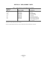
DESCRIPTION
1-1 Component Checklist of Typical System (Package Contents) . . . . . . . . . . . . . . . . . . . . . . . . . . . . . . .
1-2 System Overview . . . . . . . . . . . . . . . . . . . . . . . . . . . . . . . . . . . . . . . . . . . . . . . . . . . . . . . . . . . . . . . . .
1-1
1-1
INSTALLATION
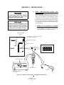
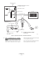
2-1 Oxygen Analyzer (Probe) Installation . . . . . . . . . . . . . . . . . . . . . . . . . . . . . . . . . . . . . . . . . . . . . . .
2-2 Intelligent Field Transmitter (IFT) Installation . . . . . . . . . . . . . . . . . . . . . . . . . . . . . . . . . . . . . . . . .
2-3 Heater Power Supply Installation . . . . . . . . . . . . . . . . . . . . . . . . . . . . . . . . . . . . . . . . . . . . . . . . . . .
2-4 Multiprobe Test Gas Sequencer Installation . . . . . . . . . . . . . . . . . . . . . . . . . . . . . . . . . . . . . . . . . . . .
2-1
2-8
2-16
2-20
GUI OPERATION
3-1 Overview . . . . . . . . . . . . . . . . . . . . . . . . . . . . . . . . . . . . . . . . . . . . . . . . . . . . . . . . . . . . . . . . . . . . . . .
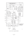
3-2 IFT with GUI and LDP Front Panel Controls and Indicators . . . . . . . . . . . . . . . . . . . . . . . . . . . . . . .
3-3 HELP Key . . . . . . . . . . . . . . . . . . . . . . . . . . . . . . . . . . . . . . . . . . . . . . . . . . . . . . . . . . . . . . . . . . . . . .
3-4 Status Line . . . . . . . . . . . . . . . . . . . . . . . . . . . . . . . . . . . . . . . . . . . . . . . . . . . . . . . . . . . . . . . . . . . . . .
3-5 Quick Reference Chart . . . . . . . . . . . . . . . . . . . . . . . . . . . . . . . . . . . . . . . . . . . . . . . . . . . . . . . . . . . . .
3-6 MAIN Menu . . . . . . . . . . . . . . . . . . . . . . . . . . . . . . . . . . . . . . . . . . . . . . . . . . . . . . . . . . . . . . . . . . . . .
3-7 PROBE DATA Sub-Menu . . . . . . . . . . . . . . . . . . . . . . . . . . . . . . . . . . . . . . . . . . . . . . . . . . . . . . . . . .
3-8 CALIBRATE O2 Sub-Menu . . . . . . . . . . . . . . . . . . . . . . . . . . . . . . . . . . . . . . . . . . . . . . . . . . . . . . . . .
3-9 SETUP Sub-Menu . . . . . . . . . . . . . . . . . . . . . . . . . . . . . . . . . . . . . . . . . . . . . . . . . . . . . . . . . . . . . . . .
3-10 System Calibration . . . . . . . . . . . . . . . . . . . . . . . . . . . . . . . . . . . . . . . . . . . . . . . . . . . . . . . . . . . . . . . .
3-1
3-1
3-2
3-2
3-2
3-3
3-3
3-3
3-3
3-8
LDP OPERATION
4-1 Overview . . . . . . . . . . . . . . . . . . . . . . . . . . . . . . . . . . . . . . . . . . . . . . . . . . . . . . . . . . . . . . . . . . . . . . .
4-2 IFT with LDP Front Panel Controls and Indicators . . . . . . . . . . . . . . . . . . . . . . . . . . . . . . . . . . . . . . .
4-3 LDP Displays . . . . . . . . . . . . . . . . . . . . . . . . . . . . . . . . . . . . . . . . . . . . . . . . . . . . . . . . . . . . . . . . . . . .
4-4 LDP Defaults . . . . . . . . . . . . . . . . . . . . . . . . . . . . . . . . . . . . . . . . . . . . . . . . . . . . . . . . . . . . . . . . . . . .
4-5 Calibration . . . . . . . . . . . . . . . . . . . . . . . . . . . . . . . . . . . . . . . . . . . . . . . . . . . . . . . . . . . . . . . . . . . . . .
4-1
4-1
4-1
4-2
4-2
SYSTEM TROUBLESHOOTING
5-1 Overview . . . . . . . . . . . . . . . . . . . . . . . . . . . . . . . . . . . . . . . . . . . . . . . . . . . . . . . . . . . . . . . . . . . . . . .
5-2 Special Troubleshooting Notes . . . . . . . . . . . . . . . . . . . . . . . . . . . . . . . . . . . . . . . . . . . . . . . . . . . . . .
5-3 System Troubleshooting . . . . . . . . . . . . . . . . . . . . . . . . . . . . . . . . . . . . . . . . . . . . . . . . . . . . . . . . . . . .
5-1
5-1
5-2
RETURNING EQUIPMENT TO THE FACTORY . . . . . . . . . . . . . . . . . . . . . . . . . . . . . . . . . . . . . .
6-1
INDEX
I-1
..........................................................................
IB-106-300NFX
xvii
TABLE OF CONTENTS (Continued)
Section
Page
APPENDIX AX. WORLD CLASS 3000 OXYGEN ANALYZER (PROBE)
(CENELEC APPROVED VERSION)
APPENDIX BX. HPS 3000 HEATER POWER SUPPLY FIELD MODULE
(CENELEC APPROVED VERSION)
APPENDIX DX.
MPS 3000 MULTI PROBE TEST GAS SEQUENCER
APPENDIX EX.
IFT 3000 INTELLIGENT FIELD TRANSMITTER
APPENDIX JX.
HART COMMUNICATOR MODEL 275D9E IFT 3000 APPLICATIONS
LIST OF ILLUSTRATIONS
Figure
1-1
1-2
1-3
2-1
2-2
2-3
2-4
2-5
2-6
2-7
2-8
2-9
2-10
2-11
2-12
2-13
2-14
2-15
2-16
2-17
2-18
2-19
3-1
3-2
3-3
3-4
3-5
4-1
Page
Typical System Package . . . . . . . . . . . . . . . . . . . . . . . . . . . . . . . . . . . . . . . . . . . . . . . . . . . . . . . . . . . . . . . .
Typical System Installation . . . . . . . . . . . . . . . . . . . . . . . . . . . . . . . . . . . . . . . . . . . . . . . . . . . . . . . . . . . . .
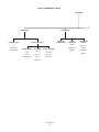
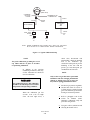
World Class 3000 Typical Application with Intelligent Field Transmitters - CENELEC Approved . . . . .
Probe Installation . . . . . . . . . . . . . . . . . . . . . . . . . . . . . . . . . . . . . . . . . . . . . . . . . . . . . . . . . . . . . . . . . . . . .
Orienting the Vee Deflector . . . . . . . . . . . . . . . . . . . . . . . . . . . . . . . . . . . . . . . . . . . . . . . . . . . . . . . . . . . . .
Air Set, Plant Air Connection . . . . . . . . . . . . . . . . . . . . . . . . . . . . . . . . . . . . . . . . . . . . . . . . . . . . . . . . . . . .
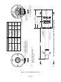
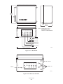
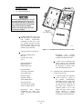
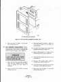
Outline of Intelligent Field Transmitter . . . . . . . . . . . . . . . . . . . . . . . . . . . . . . . . . . . . . . . . . . . . . . . . . . . .
Power Supply Board Jumper Configuration . . . . . . . . . . . . . . . . . . . . . . . . . . . . . . . . . . . . . . . . . . . . . . . . .
IFT Power Supply Board Jumpers . . . . . . . . . . . . . . . . . . . . . . . . . . . . . . . . . . . . . . . . . . . . . . . . . . . . . . . .
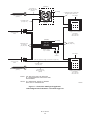
Wiring Layout for IFT 3000 System without HPS . . . . . . . . . . . . . . . . . . . . . . . . . . . . . . . . . . . . . . . . . . . .
IFT Microprocessor Board Jumper Configuration . . . . . . . . . . . . . . . . . . . . . . . . . . . . . . . . . . . . . . . . . . . .
IFT Microprocessor Board Jumpers . . . . . . . . . . . . . . . . . . . . . . . . . . . . . . . . . . . . . . . . . . . . . . . . . . . . . . .
Interconnect Board Jumper Configuration . . . . . . . . . . . . . . . . . . . . . . . . . . . . . . . . . . . . . . . . . . . . . . . . . .
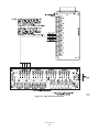
IFT Interconnect Board Output Connections . . . . . . . . . . . . . . . . . . . . . . . . . . . . . . . . . . . . . . . . . . . . . . . .
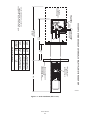
Outline of CENELEC Approved Heater Power Supply . . . . . . . . . . . . . . . . . . . . . . . . . . . . . . . . . . . . . . . .
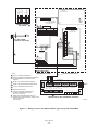
Wiring Layout for IFT 3000 (CENELEC approved) with HPS . . . . . . . . . . . . . . . . . . . . . . . . . . . . . . . . . .
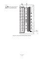
CENELEC Approved Heater Power Supply Wiring Connections . . . . . . . . . . . . . . . . . . . . . . . . . . . . . . . .
Jumper Selection Label . . . . . . . . . . . . . . . . . . . . . . . . . . . . . . . . . . . . . . . . . . . . . . . . . . . . . . . . . . . . . . . . .
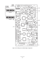
Jumpers on HPS Motherboard . . . . . . . . . . . . . . . . . . . . . . . . . . . . . . . . . . . . . . . . . . . . . . . . . . . . . . . . . . .
MPS Module . . . . . . . . . . . . . . . . . . . . . . . . . . . . . . . . . . . . . . . . . . . . . . . . . . . . . . . . . . . . . . . . . . . . . . . . .
MPS Gas Connections . . . . . . . . . . . . . . . . . . . . . . . . . . . . . . . . . . . . . . . . . . . . . . . . . . . . . . . . . . . . . . . . .
MPS Electrical Connections . . . . . . . . . . . . . . . . . . . . . . . . . . . . . . . . . . . . . . . . . . . . . . . . . . . . . . . . . . . . .
IFT with GUI and LDP Front Panel . . . . . . . . . . . . . . . . . . . . . . . . . . . . . . . . . . . . . . . . . . . . . . . . . . . . . . .
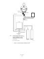
Typical Calibration Setup . . . . . . . . . . . . . . . . . . . . . . . . . . . . . . . . . . . . . . . . . . . . . . . . . . . . . . . . . . . . . . .
Portable Rosemount Oxygen Test Gas Kit . . . . . . . . . . . . . . . . . . . . . . . . . . . . . . . . . . . . . . . . . . . . . . . . . .
Typical Portable Test Calibration Setup . . . . . . . . . . . . . . . . . . . . . . . . . . . . . . . . . . . . . . . . . . . . . . . . . . . .
Typical Automatic Calibration System . . . . . . . . . . . . . . . . . . . . . . . . . . . . . . . . . . . . . . . . . . . . . . . . . . . . .
IFT with LDP Front Panel . . . . . . . . . . . . . . . . . . . . . . . . . . . . . . . . . . . . . . . . . . . . . . . . . . . . . . . . . . . . . .
IB-106-300NFX
xviii
1-1
1-5
1-6
2-2
2-7
2-8
2-9
2-10
2-11
2-12
2-13
2-14
2-14
2-15
2-16
2-17
2-19
2-19
2-20
2-21
2-21
2-23
3-1
3-10
3-11
3-12
3-13
4-1
SECTION I. DESCRIPTION
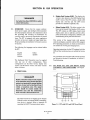
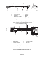
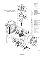
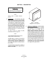
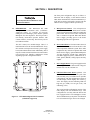
1-1.
Transmitter (CENELEC approved). The Intelligent
Field Transmitter (IFT) can be interfaced with one
World Class 3000 probe. The IFT provides all
necessary intelligence for controlling the probe and
optional MPS 3000 Multiprobe Gas Sequencer.
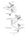
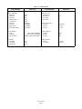
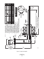
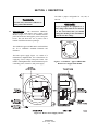
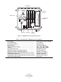
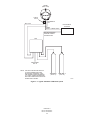
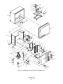
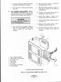
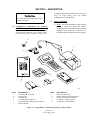
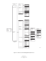
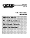
COMPONENT CHECKLIST OF TYPICAL
SYSTEM (PACKAGE CONTENTS). A typical
Rosemount World Class 3000 Oxygen Analyzer
(CENELEC approved) with IFT 3000 Intelligent Field
Transmitter (CENELEC approved) should contain the
items shown in Figure 1-1. Record the Part Number,
Serial Number, and Order Number for each component
of your system in the table located on the cover of this
manual.
The Rosemount encode sheets (Product
Ordering Matrix) allow a customer to
order either the hazardous area version
of the IFT 3000 or the non-hazardous
area version. The hazardous area version
has the symbol "EExd" on the apparatus
nameplate. The non-hazardous area
version does not. Ensure that if you have
received the non-hazardous version that
you do not install it in a potentially
explosive atmosphere. This also applies to
the hazardous/non-hazardous versions of
the HPS 3000.
The IFT 3000, Oxygen Analyzer (Probe),
and probe abrasive shield are heavy.
Lifting and carrying procedures should
take account of this weight.
1-2.
SYSTEM OVERVIEW.
a. Scope. This Instruction Bulletin has been designed
to supply details needed to install, start up,
operate, and maintain the Rosemount World
Class 3000 Oxygen Analyzer (CENELEC
approved) with IFT 3000 Intelligent Field
1
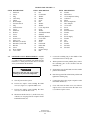
ITEM
1
2
3
4
5
6
7
8
DESCRIPTION
Intelligent Field
Transmitter (CENELEC approved)
Instruction Bulletin
Multiprobe Test Gas Sequencer
(Optional)
Heater Power Supply (CENELEC
approved)(Optional)
Oxygen Analyzer (Probe)
(CENELEC approved)
System Cable
Mounting Plate with Mounting
Hardware and Gasket
8
Reference AIR set (optional)
3
2
4
RO
SE
MO
UN
T
N
E
P
O
T
O
N
O
D
HILE
W
ENER
G
IS
E
D
S
E
EE
R
LA
BEL BEFO
7
6
Figure 1-1. Typical System Package
IB-106-300NFX
1-1
G
IN
N
E
P
O
5
23800016
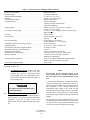
b. System Description. The Rosemount Oxygen
Analyzer (Probe) is designed to measure the net
concentration of oxygen in an industrial process;
i.e., the oxygen remaining after all fuels have
been oxidized. The probe is permanently
positioned within an exhaust duct or stack and
performs its task without the use of a sampling
system.
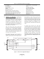
The equipment measures oxygen percentage by
reading the voltage developed across a heated
electrochemical cell, which consists of a small
Yttria-stabilized, Zirconia disc. Both sides of the
disc are coated with porous metal electrodes.
When operated at the proper temperature, the
millivolt output voltage of the cell is given by the
following Nernst equation:
basis. In comparison with older methods, such as
the Orsat apparatus, which provides an analysis on
a "dry" gas basis, the "wet" analysis will, in
general, indicate a lower percentage of oxygen.
The difference will be proportional to the water
content of the sampled gas stream.
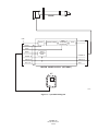
c.
System Configuration. The equipment discussed
in this manual consists of three major components:
the oxygen analyzer (CENELEC approved)
(probe), the intelligent field transmitter
(CENELEC approved) (IFT), and an optional
heater power supply (CENELEC approved) (HPS).
The HPS is required when the cable run between
the electronics and the probe exceeds 45 m (150
ft). There is also an optional multiprobe test gas
sequencer (MPS), which can be used to facilitate
the automatic calibration of a multiple probe
configuration.
EMF = KT log10(P1/P2) + C
Where:
1. P2 is the partial pressure of the oxygen in the
measured gas on one side of the cell,
2. P1 is the partial pressure of the oxygen in the
reference gas on the other side,
3. T is the absolute temperature,
4. C is the cell constant,
5. K is an arithmetic constant.
NOTE
For best results, use clean, dry, instrument
air (20.95% oxygen) as a reference gas.
When the cell is at operating temperature, and
there are unequal oxygen concentrations across the
cell, oxygen ions will travel from the high partial
pressure of oxygen side to the low partial pressure
side of the cell. The resulting logarithmic output
voltage is approximately 50 mV per decade.
Because the magnitude of the output is
proportional to the logarithm of the inverse of the
sample of the oxygen partial pressure, the output
signal increases as the oxygen concentration of the
sample gas decreases. This characteristic enables
the oxygen analyzer to provide exceptional
sensitivity at low oxygen concentrations.
Oxygen analyzer equipment measures net oxygen
concentration in the presence of all the products of
combustion, including water vapor. Therefore, it
may be considered an analysis on a "wet"
IB-106-300NFX
1-2
CENELEC approved probes are available in three
length options, giving the user the flexibility to use
an in situ penetration appropriate to the size of the
stack or duct. The options on length are 457 mm
(18 in.), 0.91 m (3 ft), and 1.83 m (6 ft). The probe
is certified EExd IIB T1 [370(C (698(F)] to
CENELEC standards EN50014 and EN50018.
The IFT contains electronics that control probe
temperature (in conjunction with the optional
HPS) and supply power, and provide isolated
outputs that are proportional to the measured
oxygen concentration. The oxygen sensing cell is
maintained at a constant temperature by
modulating the duty cycle of the probe heater. The
IFT accepts millivolt signals generated by the
sensing cell and produces outputs to be used by
remotely connected devices. The IFT output is
isolated and selectable to provide linearized
voltage or current.
The heater power supply CENELEC approved
(HPS) can provide an interface between the IFT
and the probe. The HPS contains a transformer for
supplying proper voltage to the probe heater. The
unit is certified EExd IIC T6 to CENELEC
standards EN50014 and EN50018.
Systems with multiprobe and multiple IFT
applications may employ an optional MPS 3000
Multiprobe Test Gas Sequencer. The MPS 3000
provides automatic test gas sequencing for up to
four probes and IFTs to accommodate automatic
calibration. The MPS 3000 must be installed in a
non-hazardous, explosive-free environment.
d. System Features.
e.
1. Unique and patented electronic cell protection
action that automatically protects sensor cell
when the analyzer detects reducing
atmospheres.
It is important that printed circuit
boards and integrated circuits are
handled only when adequate antistatic
precautions have been taken to prevent
possible equipment damage.
2. Output voltage and sensitivity increase as the
oxygen concentration decreases.
3. User friendly, menu driven operator interface
with context-sensitive on-line help.
The oxygen analyzer is designed for
industrial application. Treat each
component of the system with care to
avoid physical damage. The probe
contains components made from
ceramics, which are susceptible to shock
when mishandled. See Safety Data Sheets
1M03243, 1M03226, and 1M03296 for
safety related information.
4. Field replaceable cell.
5. Analyzer constructed of rugged 316 LSS for
all wetted parts.
6. The intelligent field transmitter (IFT) can be
located up to 45 m (150 ft) from the probe
when used without optional heater power
supply (HPS). When the system includes the
optional HPS, the HPS can be located up to
45 m (150 ft) from the probe and the IFT may
be located up to 364 m (1200 ft) from the
HPS.
7. All electronic modules are adaptable to 120,
220, and 240 line voltages.
8. Five languages may be selected for use with
the IFT. These are:
English
French
German
Italian
Spanish
9. An operator can set up, calibrate, or
troubleshoot the IFT in one of two ways:
(a)
Optional General User Interface (GUI).
The GUI is housed within the IFT
electronics enclosure and makes use of
an LCD display and keypad.
(b) Optional LED Display Panel (LDP).
The LED display and a limited function
keypad permit calibration only.
IB-106-300NFX
1-3
Handling the Oxygen Analyzer.
NOTE
Retain packaging in which the oxygen
analyzer arrived from the factory in case any
components are to be shipped to another site.
This packaging has been designed to protect
the product.
f.
System Considerations. Prior to installation of
your Rosemount CENELEC approved World
Class 3000 Oxygen Analyzer with Intelligent Field
Transmitter make sure that you have all of the
components necessary to make the system
installation. Ensure that all the components are
properly integrated to make the system functional.
Once you have verified that you have all the
components, select mounting locations and
determine how each component will be placed in
terms of available power supply, ambient
temperatures, environmental considerations,
convenience, and serviceability. A typical system
installation is illustrated in Figure 1-2. Figure 1-3
shows a typical system wiring. For details on
installing the individual components of the system,
refer to Section II, Installation.
After selecting the probe mounting location,
provision should be made for a platform where the
probe can be easily serviced. The intelligent field
transmitter (IFT) can be located up to 45 m (150
ft) cabling distance from the probe when used
without optional heater power supply (HPS).
When the system includes the optional HPS, the
HPS can be located up to 45 m (150 ft) cabling
distance from the probe and the IFT may be
located up to 364 m (1200 ft) cabling distance
from the HPS.
A source of instrument air is required at the probe
for reference gas use. Since the probe is
IB-106-300NFX
1-4
equipped with an in-place calibration feature,
provision should be made for connecting test gas
tanks to the oxygen analyzer when the probe is to
be calibrated.
If the test gas bottles will be permanently hooked
up, a check valve must be connected to the
calibration gas fitting on the probe junction box.
This is to prevent breathing of calibration gas line
and subsequent gas condensation and corrosion.
The check valve is in addition to the stop valve in
the test gas kit or the solenoid valve in the
multiprobe test gas sequencer units.
STANDARD
GASES
DUCT
STACK
CALIBRATION
GAS
ADAPTER
PLATE
OXYGEN
ANALYZER
EExdo IIB T1
(370 C) (PROBE)
INSTRUMENT
AIR SUPPLY
(REF. GAS)
PRESSURE
REGULATOR
HEATER POWER
SUPPLY EExd IIC T6
FLOWMETER
}
LINE
VOLTAGE
INTELLIGENT
FIELD TRANSMITTER
EExd IIB T6
GASES
OPTIONS
DUCT
STACK
ADAPTER
PLATE
*MULTIPROBE TEST
GAS SEQUENCER
(NON-HAZARDOUS AREA)
OXYGEN ANALYZER
EExd IIB T1 (370oC)
(PROBE)
TEST GAS 1
TEST GAS 2
INST. AIR
SUPPLY
CALIBRATION
GAS
REFERENCE AIR
HEATER POWER
SUPPLY EExd IIC T6
}
*NOTE: THE MPS 3000 MUST BE
INSTALLED IN A NON-HAZARDOUS
EXPLOSIVE FREE ENVIRONMENT.
LINE
VOLTAGE
INTELLIGENT
FIELD TRANSMITTER
EExd IIB T6
23800017
Figure 1-2. Typical System Installation
IB-106-300NFX
1-5
(OPTIONAL)
2-Conductor T/C
Wire [46 (150) max]
(optional)
Line Voltage
Stack Thermocouple
(optional)
4 Twisted Pair Plus 2 Twisted Pair
for Options [366 (1200) max]
Line Voltage
7-Conductor Cable
[46 (150) max]
HPS 3000
HPS 3000
IFT 3000
Intelligent Field Transmitter
World Class 3000
Probe
Line Voltage
100 to 120 Volt
220 to 240 Volt
(OPTIONAL)
Line Voltage
5 Conductor
[305 (1000) max]
*MPS 3000
2-Pneumatic Lines
by Customer
[91 (300) max]
TEST GAS
SEQUENCER
Modular Design
Up to 4 Probes
Test Gas
by
Customer
Line Voltage
[HPS not required for lengths of less than 46 (150) max]
World Class 3000
Probe
7-Conductor Cable
[46 (150) max]
Stack Thermocouple
(optional)
IFT 3000
2-Conductor T/C
Wire [46 (150) max]
(optional)
Intelligent Field Transmitter
Line Voltage
100 to 120 Volt
220 to 240 Volt
*NOTE 1: THE MPS 3000 MUST BE INSTALLED
IN A NON-HAZARDOUS EXPLOSIVE FREE
ENVIRONMENT.
NOTE 2: ALL DIMENSIONS APPEAR IN METERS
WITH FEET IN PARENTHESES.
Figure 1-3. World Class 3000 Typical Application
with Intelligent Field Transmitters - CENELEC Approved
IB-106-300NFX
1-6
23800018
SECTION II. INSTALLATION
2-1.
OXYGEN ANALYZER (PROBE)
INSTALLATION.
2. Check the flue or stack for holes and air
leakage. The presence of this condition will
substantially affect the accuracy of the
oxygen reading. Therefore, either make
necessary repairs or install the probe
upstream of any leakage.
Before probe installations, consult probe
Safety Data Sheet 1M03226.
3. Ensure that the area is clear of obstructions
internal and external that will interfere with
installation. Allow adequate clearance for
removal of probe (Figure 2-1).
The probe and probe abrasive shield are
heavy. Use proper lifting and carrying
procedures to avoid personnel injury.
Do not allow the temperature of the
probe junction box to exceed 150C
(302F) or damage to the unit may
result. If the probe junction box
temperature exceeds 150C (302F), the
user must fabricate a heat shield or
provide adequate cooling air to the probe
junction box.
Install all protective equipment covers
and safety ground leads after installation.
Failure to install covers and ground leads
could result in serious injury or death.
b. Mechanical Installation.
a. Selecting Location.
1. The location of the probe in the stack or flue
is most important for maximum accuracy in
the oxygen analyzing process. The probe
must be positioned so that the gas it
measures is representative of the process.
Best results are normally obtained if the
probe is positioned near the center of the
duct (40 to 60% insertion). A point too near
the edge or wall of the duct may not provide
a representative sample because of the
possibility of gas stratification. In addition,
the sensing point should be selected so that
the process gas temperature falls within a
range of 10 to 704C (50 to 1300F).
Figure 2-1 provides you with mechanical
installation references.
IB-106-300NFX
2-1
1. Ensure that all components are available for
installation of the probe. Check the ceramic
filter to ensure that it is not damaged and that
the system cable is the required length.
2. The probe may be installed intact as it is
received. It is recommended that you
disassemble the adapter plate for each
installation.
3. Weld or bolt adapter plate (Figure 2-1) onto
the duct.
Figure 2-1. Probe Installation (Sheet 1 of 5)
IB-106-300NFX
2-2
NOTE:
23800006
1U05680G03
6 FT PROBES
170
(6.693)
4 HOLES EQ
SP ON B.C. DIA
A
A
BOTTTOM VIEW
2126
(83.7)
1209
(47.6)
755
(29.7)
DIM
"B"
110 (4.33)
200 (7.87)
B
ELECTRICAL
CONNECTION
B
DIM "B"
REMOVAL ENVELOPE
(ROTATED 90o CCW)
INSTALL WITH CONNECTIONS
AT BOTTOM
INTERNAL EARTH
(TERMINAL 6) VIEW B-B
EXTERNAL EARTH
(HARDWARE)
1831
(72.09)
913
(35.95)
459
(18.07)
DIM
"A"
CENELEC APPROVED WORLD CLASS PROBE WITH SNUBBER DIFFUSOR
76 (3.0)
DIA MAX
DIM "A"
1.57 (0.062)
THK GASKET
(P/N 1M03237H01)
1U05680G02
3 FT PROBES
18
(0.708)
HOLE SIZE
DIA
DIMENSIONS ARE IN MILLIMETERS WITH
INCHES IN PARENTHESES UNLESS
OTHERWISE INDICATED.
VIEW A-A
1U05680G01
18 IN. PROBES
210
(8.25)
FLANGE
DIA
PROCESS FLOW MUST BE IN
THIS DIRECTION WITH RESPECT
TO VEE SHIELD WHEN USING
OPTIONAL CERAMIC DIFFUSOR.
DIMENSIONS
MM
(IN.)
DIN
TABLE II. REMOVAL/INSTALLATION
DIMENSIONS
MM
(IN.)
TABLE I. MOUNTING FLANGE
23800007
Figure 2-1. Probe Installation (Sheet 2 of 5)
IB-106-300NFX
2-3
843
(33.2)
1762
(69.4)
3 FT PROBE 1U05680G05
SHIELD 1N04966H02
6 FT PROBE 1U05680G06
SHIELD 1N04966H03
2144
(84.4)
1224
(48.2)
769
(30.3)
CHECK
VALVE
ELECTRICAL
CONNECTION
SEE SHEET 1
FOR CONNECTION
DETAILS
NOTE: DIMENSIONS ARE IN MILLIMETERS
WITH INCHES IN PARENTHESES
UNLESS OTHERWISE INDICATED.
DIM "D"
(REMOVAL
ENVELOPE)
REF, VENT,
AND CAL GAS
CONNECTIONS
378
(14.9)
DIM "D"
(REMOVAL
ENVELOPE)
ABRASIVE SHIELD INSTALLATION WITH CENELEC APPROVED WORLD CLASS 3000
DIFFUSOR/DUST
SEAL HUB
(P/N 1U05677G03)
178
(7.00)
387
(15.3)
18 IN. PROBE 1U05680G04
SHIELD 1N04966H01
1.52 (0.06) THK GASKET
(P/N 4507C52H03)
FURNISHED IN
HARDWARE PACKAGE
DIM "C"
DIM
"C"
DIMENSIONS
MM
(IN.)
REMOVAL/INSTALLATION
Figure 2-1. Probe Installation (Sheet 3 of 5)
IB-106-300NFX
2-4
NOTE:
23800011
1U05680G03
6 FT PROBES
170
(6.693)
4 HOLES EQ
SP ON B.C. DIA
A
A
BOTTTOM VIEW
2126
(83.7)
1209
(47.6)
755
(29.7)
DIM
"B"
110 (4.33)
200 (7.87)
B
ELECTRICAL
CONNECTION
B
DIM "B"
REMOVAL ENVELOPE
(ROTATED 90o CCW)
INSTALL WITH CONNECTIONS
AT BOTTOM
INTERNAL EARTH
(TERMINAL 6) VIEW B-B
EXTERNAL EARTH
(HARDWARE)
1926
(75.83)
1008
(39.68)
554
(21.81)
DIM
"A"
OPTIONAL CERAMIC DIFFUSOR WITH VEE DEFLECTOR
76 (3.0)
DIA MAX
DIM "A"
1.57 (0.062)
THK GASKET
(P/N 1M03237H01)
1U05680G02
3 FT PROBES
18
(0.708)
HOLE SIZE
DIA
DIMENSIONS ARE IN MILLIMETERS WITH
INCHES IN PARENTHESES UNLESS
OTHERWISE INDICATED.
VIEW A-A
1U05680G01
18 IN. PROBES
210
(8.25)
FLANGE
DIA
PROCESS FLOW MUST BE IN
THIS DIRECTION WITH RESPECT
TO VEE SHIELD.
DIMENSIONS
MM
(IN.)
DIN
TABLE II. REMOVAL/INSTALLATION
DIMENSIONS
MM
(IN.)
TABLE I. MOUNTING FLANGE
Figure 2-1. Probe Installation (Sheet 4 of 5)
IB-106-300NFX
2-5
100
(3.94)
M-20 x 2.5
"B"
DIA
"C"
THREAD
"C"
"B"
"A"
22.5o
82.5 (3.25)
DIA
"C" DIA
"A"
MOUNTING PLATE FOR
CENELEC WORLD CLASS 3000
PROBE INSTALLATIONS
SEE SHEET 1.
170
(6.7)
M-16 x 2
215
(8.5)
DIN
4 STUDS, LOCKWASHERS,
AND NUTS, EQUALLY
SPACED ON "C" DIA B.C.
"C"
DIA
"B"
THREAD
"A"
DIMENSIONS
MM
(IN.)
NOTE: DIMENSIONS ARE IN MILLIMETERS
WITH INCHES IN PARENTHESES
UNLESS OTHERWISE INDICATED.
"A"
235
(9.25)
DIN
"A"
DIMENSIONS
MM
(IN.)
TABLE IV. MOUNTING PLATE:
PROBE TO STACK
(NEW INSTALLATIONS)
MOUNTING PLATE OUTLINE
TABLE III. MOUNTING PLATE:
ABRASIVE SHIELD TO STACK
(NEW INSTALLATIONS)
MOUNTING PLATE FOR
18 IN., 3 FT AND 6 FT
ABRASIVE SHIELD INSTALLATIONS
SEE SHEET 2.
8 THREADED HOLES
EQUALLY SPACED ON
189.992 (7.48) DIA B.C.
P00006
"A"
INSTALLATION FOR METAL
WALL STACK OR DUCT
CONSTRUCTION
INSTALLATION FOR MASONRY
WALL STACK CONSTRUCTION
13 (0.50)
13 (0.50)
BOLT ADAPTOR
PLATE TO OUTSIDE
WALL SURFACE
FIELD WELD
PIPE TO
ADAPTOR PLATE
95 (3.75)
MTG HOLES
SHOWN ROTATED
22.5o OUT OF
TRUE POSITION
MIN DIA HOLE
IN WALL
STACK OR DUCT
METAL WALL
MTG HOLES
SHOWN ROTATED
22.5o OUT OF
TRUE POSITION
JOINT MUST
BE AIRTIGHT
WELD OR BOLT
MOUNTING PLATE TO
METAL WALL OF STACK
OR DUCT. JOINT MUST
BE AIR TIGHT.
114 (4.50)
O.D. REF
PIPE 4.00 SCHED 40
PIPE SLEEVE (NOT
BY ROSEMOUNT)
LENGTH BY CUSTOMER
MASONRY
STACK WALL
OUTSIDE WALL
SURFACE
NOTE:
ALL MASONRY STACK WORK AND JOINTS EXCEPT
MOUNTING PLATE NOT FURNISHED BY ROSEMOUNT.
ABRASIVE SHIELD MOUNTING
BOLT MOUNTING
PLATE TO OUTSIDE
WALL SURFACE
FIELD WELD
PIPE TO
ADAPTOR PLATE
102 (4.0)
O.D. REF
82.5 (3.25)
MIN DIA HOLE
IN WALL
STACK OR DUCT
METAL WALL
JOINT MUST
BE AIRTIGHT
WELD OR BOLT MOUNTING
PLATE TO METAL WALL
OF STACK OR DUCT.
JOINT MUST BE AIR TIGHT.
OUTSIDE WALL
SURFACE
PROBE MOUNTING
Figure 2-1. Probe Installation (Sheet 5 of 5)
IB-106-300NFX
2-6
PIPE 3.5 SCHED 40
PIPE SLEEVE (NOT
BY ROSEMOUNT)
LENGTH BY CUSTOMER
MASONRY
STACK WALL
P00007
4. If using the optional ceramic diffuser
element, the vee deflector must be correctly
oriented. Before inserting the probe, check
the direction of flow of the gas in the duct.
Orient the vee deflector on the probe so that
the apex points upstream toward the flow
(Figure 2-2). This may be done by loosening
the setscrews, and rotating the vee deflector
to the desired position. Retighten the
setscrews.
GAS FLOW
DIRECTION
APEX
VEE
DEFLECTOR
CERAMIC
DIFFUSION
ELEMENT
FILTER
VEE
DEFLECTOR
5. In horizontal installations, the probe cover
should be oriented so that the system cable
drops vertically from the probe cover. In a
vertical installation, the system cable can be
oriented in any direction.
SETSCREW
23800008
Figure 2-2. Orienting the Optional Vee Deflector
6. If the system has an abrasive shield, check
the diffusion element dust seal packings. The
joints in the two packings must be staggered
180. Also, make sure that the packings are
in the hub grooves as the probe slides into
the 15 forcing cone in the abrasive shield.
7. Insert the probe through the opening in the
mounting flange and bolt the unit to the
flange.
NOTE
8. Ensure that probe is properly earthed by way
of both the internal and external points.
If process temperatures will exceed 1000F
(538C), use anti-seize compound on stud
threads to ease future removal of probe.
9. Ensure that the installation does not obscure
the messages on either the probe nameplate
or the junction box lid.
IB-106-300NFX
2-7
c.
Reference Air Package. After the oxygen
analyzing (probe) unit is installed, connect the
reference gas air set to the probe cover. The
reference gas air set should be installed in
accordance with Figure 2-3.
2-2.
INTELLIGENT FIELD TRANSMITTER (IFT)
INSTALLATION.
The Rosemount Encode Sheet (Product
Ordering Matrix) allows a customer to
order either the hazardous area version
of the IFT 3000 or the non-hazardous
area version. The hazardous area version
has the symbol "EExd" on the apparatus
nameplate. The non-hazardous area
version does not. Ensure that if you have
the non-hazardous area version that you
do not install it in a potentially explosive
environment. This warning applies
equally to the hazardous area and nonhazardous area versions of the HPS 3000.
d. Service Required.
1. Power input: 44 VAC from HPS 3000 or IFT
3000.
2. Compressed air: 68.95 kPa (10 psig)
minimum, 1551.38 kPa (225 psig) maximum
at 56.6 L/hr (2 scfh) maximum; supplied by
one of the following (less than 40 parts-permillion total hydrocarbons).
(a)
Instrument air - clean, dry.
(b) Bottled standard air with step-down
regulator.
(c)
Bottled compressed gas mixture
(20.95% oxygen in nitrogen).
Before IFT 3000 Installation, consult
Safety Data Sheet 1M03296.
(d) Other equivalent clean, dry, oil-free air
supply.
0.125-27 NPT FEMALE
OUTLET CONNECTION
1
2
79.25 (3.12) MAX
OUTLET
57.15 (2.250)
3
122.17 (4.81)
FLOW SET
POINT KNOB
NOTE: DIMENSIONS ARE IN MILLIMETERS
WITH INCHES IN PARENTHESES.
0.25-18 NPT FEMALE
INLET CONNECTION
30.22
(1.19)
50.80
(2.0)
DRAIN VALVE
38.10
(1.50)
215.90 MAX
(8.50)
2 MOUNTING HOLES
81.03 (3.19) LG
THROUGH BODY FOR
7.92 (0.312) DIA BOLTS
254 REF
(10.0)
6 (0.250) OD
TUBE COMPRESSION
FITTING (SUPPLIED BY WECO)
TO PROBE
JUNCTION BOX
1
2
3
FLOWMETER
0.2-2.0 SCFH 771B635H02
2" PRESSURE GAGE
0-15 PSIG
275431-006
COMBINATION FILTER-REG. 0-30 PSIG
4505C21G01
COMPRESSED AIR SUPPLY
10-225 PSIG MAX PRESSURE
6 (0.250) OD TUBING
(SUPPLIED BY CUSTOMER)
REF GAS SET
263C152G01
NOTE: DIMENSIONS ARE IN MILLIMETERS
WITH INCHES IN PARENTHESES.
SCHEMATIC HOOKUP FOR REFERENCE AIR SUPPLY ON OXYGEN ANALYZER PROBE HEAD.
Figure 2-3. Air Set, Plant Air Connection
IB-106-300NFX
2-8
17300016
install JM8, JM7, and JM1. For 220 Vac
usage, install jumpers JM6, JM5, JM2 (refer
to Figures 2-5 and 2-6).
The IFT 3000 is heavy. Lifting and
carrying procedures should take account
of this weight.
a. Mechanical Installation. The outline drawing of
the IFT module (CENELEC approved) in Figure
2-4 shows mounting centers and clearances. The
enclosure is designed to be mounted on a wall.
The IFT should be installed no more than 364 m
(1200 ft) from the optional HPS or 45 m (150 ft)
from the probe if HPS is not installed in the
system. Ambient temperature must be between
0C and 50C (32F and 122F).
If you reconfigure the equipment for a
line voltage other than the one marked
on the serial label and the mains filter of
the power supply you should change the
marking on the serial label and the mains
filter to state the new line voltage.
NOTE
b. Electrical Connections.
Fuse specifications
Figure 2-4.
1. The IFT can be configured for 100, 120,
220, or 240 line voltages. For 120 Vac usage,
310 (12.2)
18 (0.7)
270 (10.6)
300
(11.8)
EXTERNAL
EARTH
320
(12.6)
225
(8.9)
350
(13.8)
FUSES
INTERNAL
EARTH
350 (13.8)
NOTES: ALL DIMENSIONS ARE IN MILLIMETERS WITH INCHES IN PARENTHESES UNLESS
OTHERWISE INDICATED.
FUSES SHOWN (F3 THROUGH F6) ARE 5 AMP, ANTI-SURGE, TYPE T TO IEC127
(ROSEMOUNT PART NUMBER 1L01293H02). IF INTERNAL HEATER IS INSTALLED,
TWO ADDITIONAL 5 AMP FUSES (F1 AND F2) ARE USED.
Figure 2-4. Outline of Intelligent Field Transmitter
IB-106-300NFX
2-9
are
included
in
ALWAYS DISCONNECT LINE VOLTAGE
FROM INTELLIGENT FIELD TRANSMITTER
BEFORE CHANGING JUMPERS.
JUMPER
CONFIGURATION
JUMPER
(INSTALL)
PROBE HEATER
VOLTAGE SELECTION
JUMPER
(INSTALL)
120 V.A.C.
JM8, JM7, JM1
WORLD CLASS PROBE (44V)
JM10
220 V.A.C.
JM6, JM5, JM2
240 V.A.C.
JM6, JM5, JM1
LINE VOLTAGE
SELECTION
P00010
If you reconfigure the equipment for a line voltage other than the one marked on the serial
label and the mains filter of the power supply then you should change the marking on the
serial label and the mains filter to state the new line voltage.
If incorrect heater voltage is selected, damage to the probe may occur. For HPS voltage
selection jumper, refer to Figure 2-15.
Figure 2-5. Power Supply Board Jumper Configuration
2. The IFT can be configured to connect
directly to a probe or to an optional HPS.
The electrical connections for a non-HPS
equipped system should be made as
described in the electrical installation
diagram, Figure 2-7.
must be installed on the interconnect board.
Remove wire jumper if MPS is installed in
the system. Refer to Figure 2-7, note 6.
5. The power cable should comply with the
safety regulations in the user's country and
should not be smaller than 16 gauge, 3 amp.
6. Before supplying power to the IFT, verify
that the jumpers have been properly set in
the IFT, Figures 2-5, 2-8, and 2-10.
Do not install jumper JM6 on the
microprocessor board, or JM1 on the
interconnect board, if an HPS is installed
in the system. This will result in system
failure.
7. Terminal strip J5 on the power supply board
is used for supplying the IFT with power.
Terminal strip J6 on the power supply board
is used to supply the probe heater with power
if an HPS is not used (Figure 2-6).
3. The IFT must have JM6 on the
microprocessor board (Figures 2-8 and 2-9)
and JM1 on the interconnect board (Figures
2-10 and 2-11) installed if an HPS is not
installed in the system.
4. If an MPS is not used in the system, wire
jumper between CAL RET and NO GAS
IB-106-300NFX
2-10
8. Ensure that the IFT 3000 is properly earthed
by way of both the internal and external
earthing hardware.
9. Ensure that the installation does not obscure
the message on either the IFT nameplate or
the IFT lid.
THIS TERMINAL BLOCK
IS A 44VAC OUTPUT
SPECIFICALLY FOR
POWERING THE
WC 3000 PROBE.
!
P00011
Figure 2-6. IFT Power Supply Board Jumpers
IB-106-300NFX
2-11
HEATER
BK
GN
}
3D3911BG REV
MICROPROCESSOR BOARD
BK
RD ALUMEL
YE CHROMEL
OR CELL +VE
GN CELL -VE
PROBE INTERIOR
LG. BR
BL
GN/YE
GN
RD
WH
SM. BR
1 2 3 4 5 6 7 8
3D39122G REV
POWER SUPPLY BOARD
J1
JM6 JM5
ALWAYS DISCONNECT LINE VOLTAGE
FROM INTELLIGENT FIELD TRANSMITTER
BEFORE CHANGING JUMPERS.
PROBE JUNCTION
BOX WIRING
JUMPER CONFIGURATION
LINE
VOLTAGE
JUMPER
SECTION
(INSTALL)
120 V.A.C. JM8, JM7, JM1
220 V.A.C. JM6, JM5, JM2
240 V.A.C. JM6, JM5, JM1
J1
3D39120G REV
INTERCONNECT BOARD
J2
JUMPER
PROBE HEATER
VOLTAGE SECTION (INSTALL)
WORLD CLASS PROBE JM10
218 PROBE
JM9
J3
J4
J5
WC 3000 PROBE
(CENELEC APPROVED)
CAL RET
NO GAS
J6
J6
J5
SHIELD
STACK TC STACK TC +
J7
LO GAS
HI GAS
IN GAS
SHIELD
J8
SHIELD
GN PROBE TC RD PROBE TC +
SHIELD
WH PROBE MV SM.BR PROBEMV+
H R E
L N E
J9
LINE
VOLTAGE
JM1
LG. BR
BL
GN/YE
SHIELD
SM. BR
WH
GN
RD
INTELLIGENT FIELD
TRANSMITTER IFT3000
NOTES
5 CONDUCTOR SHIELDED CABLE
PER PROBE #16 AWG BY CUSTOMER
STACK TC WIRING AS REQUIRED
NC C NO
IF MPS 3000 NOT USED
1 RELAY PER PROBE AVAILABLE FOR
CALIBRATION STATUS INDICATION
(48 V max, 100 mA max)
CABLE COLORS SHOWN HERE APPLY TO
ROSEMOUNT SUPPLIED SPECIAL CABLE FITTED
WITH EExd GLANDS
(P/N 1U03066)
NC C NO
NC C NO
J8
LO GAS
NO GAS
IN CAL
PROBE 4
CAL RET
HI GAS
LO GAS
J6 J7
NO GAS
IN CAL
CAL RET
HI GAS
LO GAS
NO GAS
IN CAL
3D39064G REV
PROBE 2
PROBE 3
J4 J5
CAL RET
HI GAS
J2 J3
LO GAS
N
J10
NO GAS
IF STACK TEMPERATURE NOT USED
PROBE 1
IN CAL
INSTALL JM6 ON MICROPROCESSOR BOARD
HI GAS
INSTALL JM1 ON INTERCONNECT BOARD
LINE OUT J1
L
CAL RET
SPECIAL PROBE CABLE BETWEEN PROBE AND
IFT BY ROSEMOUNT (FITTED WITH EExd
GLANDS)
LINE IN J9
L
L
E LINE
N
N
VOLTAGE
NC C NO
J11
J13
J14
J15
J16
J17
J18
J12
J19
J20
J21
J22
PROBE 1
PROBE 2
PROBE 3
PROBE 4
MPS TERMINATION BOARD
MPS3000 MULTI GAS SEQUENCER (OPTIONAL)
23800019
Figure 2-7. Wiring Layout for IFT 3000 (CENELEC approved) System without HPS
IB-106-300NFX
2-12
P00013
Figure 2-8. IFT Microprocessor Board Jumper Configuration
IB-106-300NFX
2-13
c.
Analog Output and Relay Output Connections.
1. The microprocessor board has a socket for a
dip shunt to select voltage or current
operations. Figure 2-8 shows the dip shunt
orientation. In voltage mode, output is
0-10 V. In the current mode, the output can
be configured from the setup menu to be
0-20 mA or 4-20 mA.
2. The analog output and relay outputs are
programmed by the user as needed. The
analog output is typically sent to recording
equipment such as chart recorders. Relay
outputs are typically sent to annunciators.
3. Relays K1 and K2 are user configurable from
the PROBE SETUP sub-menu (Table 3-5).
Typically these are used to indicate O2
values above or below specified tolerances.
OK relay is energized when unit is
functioning properly.
BIT BUS ADDRESS
JUMPER
(Not Used)
JM1, JM2, JM3, JM4
BIT BUS
JUMPER
Resistor Terminated
Resistor Not Terminated
Install JM5
Remove JM5
OUTPUT
JUMPER
HPS
Probe (No HPS)
Remove JM6
Install JM6
(See Figure 2-8 for jumper locations.)
Figure 2-9. IFT Microprocessor Board Jumpers
OUTPUT
JUMPER
HPS
Probe (No HPS)
Remove JM1
Install JM1
Figure 2-10. Interconnect Board Jumper Configuration
4. All wiring must conform to local and
national codes.
IB-106-300NFX
2-14
5. Connect the analog output and relay outputs
as shown in Figure 2-11.
NOTES:
DENOTES SHIELD CONNECTION.
24
OK-NC 23
22
K1-NC 21
20
K2-NC 19
OK RELAY IS ENERGIZED WHEN
UNIT IS FUNCTIONING PROPERLY.
24 OK-COM
23 OK-NO
22
21
20
19
18
18
17
CAL INIT-2 17
16
CAL INIT-1 16
15
15
14
CALRET 14
13
NOGAS 13
12
LOGAS 12
11
HIGAS 11
10
INCAL 10
9
9
8
RELAY- 8
7
RELAY+ 7
6
6
5
AD590- 5
4
AD590+ 4
3
3
2
TRIAC- 2
1
TRIAC+
1
K1-COM
K1-NO
K2-COM
K2-NO
ANOUTANOUT+
STACK T/C
STACK T/C
PROBE T/C
PROBE T/C
PROBE MVPROBE MV+
JM1
(UNDER
SHIELD)
730002
Figure 2-11. IFT Interconnect Board Output Connections
IB-106-300NFX
2-15
2-3.
HEATER POWER SUPPLY INSTALLATION.
2. Power Input: 120, 220 or 240 Vac. For
120 Vac usage, install jumpers JM4 and JM1
and remove JM5 if installed. For 220 or 240
Vac usage, install jumper JM5 and remove
JM1 and JM4 if installed (see label,
Figure 2-15).
The Rosemount encode sheets (Product
Ordering Matrix) allow a customer to
order either the hazardous area version
of the HPS 3000 or the non-hazardous
area version. The hazardous area version
has the symbol "EExd" on the apparatus
nameplate. The non-hazardous area
version does not. Ensure that if you have
received the non-hazardous version that
you do not install it in a potentially
explosive atmosphere. This also applies
to the hazardous/non-hazardous version
of the IFT 3000.
If you reconfigure the equipment for a
line voltage other than the one marked
on the serial label and the mains filter of
the power supply then you should change
the marking on the serial label and the
mains filter to state the new line voltage.
NOTE
Fuse specifications are shown in Figure 2-14.
Before HPS installation, consult Safety
Data Sheet 1M03243.
3. The power cable should comply with safety
regulations in the user's country and should
not be smaller than 16 gauge, 3 amp.
a. Mechanical Installation. The outline drawing of
the CENELEC approved heater power supply
enclosure in Figure 2-12, shows mounting centers
and clearances. The CENELEC approved
enclosure is designed to be mounted on a wall or
bulkhead. The heater power supply should be
installed no further than 45 m (150 ft) from the
probe. The heater power supply must be located
in a location free from significant ambient
temperature changes and electrical noise.
Ambient temperature must be between 0 to 60C
(32 to 140F).
264.0
(10.39)
253
(9.96)
216.0
(8.50)
b. Electrical Connections.
1. Electrical connections should be made as
described in the electrical installation
diagram, Figure 2-13. The wiring terminals
are divided into two layers: the bottom
(FROM PROBE) terminals should be
connected
first,
the
top
(FROM
ELECTRONICS) terminals should be
connected last (Figure 2-14). Each terminal
strip has a protective cover which must be
removed when making connections. To
remove the terminal covers, remove two
slotted screws holding cover in place.
Always reinstall terminal covers after
making connections.
233
(9.17)
EExd IIC T6
ENCLOSURE
14.22 (0.56) DIA
MTG HOLE (2 PLS)
120
(4.72)
NOTE: DIMENSIONS ARE IN MILLIMETERS
WITH INCHES IN PARENTHESES
UNLESS OTHERWISE INDICATED.
157
(6.18)
219005
Figure 2-12. Outline of CENELEC Approved Heater
Power Supply
IB-106-300NFX
2-16
NOTES
HEATER
RELAY WIRE IS OPTIONAL; RELAY CAN BE PERMANENTLY
ENABLED WITH JUMPER IF NOT USED
}
STACK TC WIRING AS REQUIRED
BK
GN
BK
RD ALUMEL
YE CHROMEL
OR CELL +VE
GN CELL -VE
PROBE INTERIOR
ALL WIRES #16-#22 AWG TWISTED PAIR WITH SHIELD
BY CUSTOMER EXCEPT AS NOTED
SPECIAL PROBE CABLE BETWEEN PROBE AND HPS
BY ROSEMOUNT
LG. BR
BL
GN/YE
GN
RD
WH
SM. BR
1 2 3 4 5 6 7 8
REMOVE JM1 ON INTERCONNECT BOARD (IFT 3000)
REMOVE JM6 ON MICROPROCESSOR BOARD
PROBE JUNCTION
BOX WIRING
IF RELAY WIRE OF NOTE 1 INSTALLED THEN REMOVE
JM2 ON HPS 3000
IF STACK TEMPERATURE NOT USED
IF MPS 3000 NOT USED
1 RELAY PER PROBE AVAILABLE FOR CALIBRATION
STATUS INDICATION (48 V max, 100 mA max)
CABLE COLORS SHOWN HERE APPLY TO ROSEMOUNT
SUPPLIED SPECIAL CABLE FITTED WITH EExd GLANDS
(P/N 1U03066)
WC PROBE 3000 CENELEC APPROVED
ALWAYS DISCONNECT LINE VOLTAGE
FROM HEATER POWER SUPPLY AND
ANALOG ELECTRONICS (IF USED)
BEFORE CHANGING JUMPERS.
JUMPER
CONFIGURATIONS
LINE VOLTAGE
SELECTION
JUMPER
(INSTALL)
HEATER
POWER
JUMPER
120 V.A.C.
JM4, JM1
REMOTE
REMOVE JM2
220/240 V.A.C.
JM5
ON
INSTALL JM2
PROBE HEATER
VOLTAGE SECTION
JUMPER
(INSTALL)
ELECTRONICS
SELECTION
JUMPER
WORLD CLASS PROBE
JM7
NEW GENERATION
ELECTRONICS
REMOVE JM3, JM6
TOP
TRIAC RELAY
J9
STACK
TC
+ - + - + -
ANALOG
HEATER
BK WH
2 TWISTED PAIR SHIELDED
#22 AWG BY CUSTOMER
(OPTIONAL)
A
PROBE PROBE
TC AD590
MV
J8
+ - + - + -
B
BOTTOM
PROBE
MV
SM. BR CELL+
WH CELL -
J3
+ -
PROBE
TC
4 TWISTED PAIR SHIELDED
#22 AWG BY CUSTOMER
+ -
RD HTR TC +
GN HTR TC BL
LG. BR
GN/YE
STACK
TC
J2
+ -
PROBE
HEATER
R H
LINE
J1
N L
LINE
VOLTAGE
SHIELD
HPS 3000 INTERFACE MODULE
23800020
Figure 2-13. Wiring Layout for IFT 3000 (CENELEC approved) with HPS (Sheet 1 of 2)
IB-106-300NFX
2-17
j
I------.----.---‘--_“--__“___-_______---__
-7
50391leC
MICROPROCESSOR
BOARD
I
- I
I
I
I
IO -
I
I.
I
I
I
I
I
I
uN~E%Lrr~”
100 V.A.C.
120 V.A.C.
200 V.A.C.
220 V.A.C.
240 V.A.C.
lz
3D39122G
Jl
JmER SUPPLY
eom
ALWAYS DISCONNECT m
VOtlAcE
FROM INmLlGENl
FlELD lRANsMIllER
BEFORE CHANCING JUMPERS
3JhIPER CONflCURAPCN ]
_(
JUMPER
PRO% HEATER
( INSTALL)
(i!?lz!)
KITACE mm
JM3. JM7. JM2
NOT USED
REMOM
JMB. JM7. JMI
JM9. YlO
JM4. JM5. JM2
JM6. JMS. 3.2
JM6. Jus. JMl
I
0
REV
aCARD
0
0
-I
I
I
I
I
I
I
I
I
Jl
JDJ912DG
INTERCCNNEC?
J5
L
1
*
(3
rJ6
088
I I I
LNE
I
“NE vOLTACE
0
0
J
NOT USED
-.--
PROBE TC -
-----_-__-__v
1
t
I
_-__-__-__-__-__
INTELUGENT RELD TRANSMITTER IFr3000
-
A
MPS3000
5 CONDUCTOR
SKl.DEb CABLE
PER PROBE #16 AWC ar
CUSTOUER
MPS TERMlNAllON BOARD
MULTIPROBE GAS SEQUENCER (OPTIONAL)
Figure 2-13. Wiring Layout for IFT 3000 (CENELEC approved) with HPS (Sheet 2 of 2)
IB-lD6-3DCNFX
218
Figure 2-14. CENELEC Approved Heater Power Supply Wiring Connections
219007
Figure 2-15. Jumper Selection Label
If you reconfigure the equipment for a line voltage other than the one marked on the serial
label and the mains filter of the power supply then you should change the marking on the
serial label and the mains filter to state the new line voltage.
IB-106-300NFX
2-19
JM8
3D3 080G REV
Before supplying power to the heater
power supply, verify that jumpers JM3
and JM6 are removed, and JM7 is
installed. If relay wire (Figure 2-13,
Note 1) is installed, JM2 must be
removed from HPS Motherboard
(Figure 2-16).
JM6
JM7
JM5
JM4
JM2
4. Before supplying power to the heater power
supply, verify that the jumpers on the
motherboard, Figure 2-16, are properly
configured. Jumpers JM3, JM6, should be
removed and JM7 should be installed.
Additionally, make sure that the proper
jumper for your line voltage is installed,
Figure 2-15. If relay wire (Figure 2-13, note
1) is not installed, JM2 should be installed on
the HPS Motherboard (Figure 2-16).
JM1
JM3
219008
Figure 2-16. Jumpers on HPS Motherboard
NOTE
5. Ensure that the HPS 3000 is properly earthed
by way of both the internal and external
earthing points.
6. Ensure the installation does not obscure the
messages on either the HPS nameplate or
HPS lid.
NOTE
Refer to Figures 2-8 and 2-10 for proper IFT
jumper configuration. IFT microprocessor
and
interconnect
board
jumper
configurations must be set correctly in order
for HPS to work properly.
2-4.
A Z-Purge option is available for the
MPS 3000. Appendix DX contains
information concerning the Z-Purge.
a. Mechanical Installation. The outline drawing of
the MPS module in Figure 2-17 shows mounting
centers and clearances. The box is designed to be
mounted on a wall or bulkhead. The MPS module
should be installed no further than 91 m (300 ft)
piping distance from the probe, and no more than
303 m (1000 ft) cabling distance from the IFT.
Install the MPS module in a location where the
ambient temperature is between -30 and 71C
(-20 and 160F).
b. Gas Connections. Figure 2-18 shows the bottom
of the MPS where the gas connections are made.
1/4 in. threaded fittings are used.
MULTIPROBE TEST GAS SEQUENCER
INSTALLATION.
1. Connect the reference air supply to INSTR.
AIR IN. The air pressure regulator valve is
set at the factory to 138 kPa (20 psi). If the
reference air pressure should need
readjustment, turn the knob on the top of the
valve until the desired pressure is obtained.
The MPS 3000 Multiprobe Test Gas
Sequencer must be installed in a nonhazardous, explosive-free environment.
2. Connect the high O2 test gas to HIGH GAS.
The test gas pressure should be set at
138 kPa (20 psi).
IB-106-300NFX
2-20
304.80
(12.00)
254.00
(10.00)
304.80
(12.00)
HIGH CAL
GAS IN
LOW CAL
GAS IN
PROBE 1
PROBE 2
PROBE 3
PROBE4
TEST GAS
OUT
TEST GAS
OUT
TEST GAS
OUT
TEST GAS
OUT
REF AIR
OUT
REF AIR
OUT
REF AIR
OUT
NOTE: DIMENSIONS ARE IN
MILLIMETERS WITH
INCHES IN PARENTHESES.
REF AIR
OUT
INSTR
AIR
21.34 (0.84)
49.78 (1.96)
78.49 (3.09)
106.93 (4.21)
133.35 (5.25)
140.72 (5.54)
355.60 (14.00) REF
712010
Figure 2-17. MPS Module
LINE IN
HIGH CAL
GAS IN
DRAIN
LOW CAL
GAS IN
PROBE 1
PROBE 2
PROBE 3
PROBE4
TEST GAS
OUT
TEST GAS
OUT
TEST GAS
OUT
TEST GAS
OUT
REF AIR
OUT
REF AIR
OUT
REF AIR
OUT
REF AIR
OUT
SIGNAL IN
INSTR
AIR
459013
Figure 2-18. MPS Gas Connections
IB-106-300NFX
2-21
c.
Do not use 100% nitrogen as a low (zero)
gas. It is suggested that the low gas be
between 0.4% and 2.0% O2. Do not use
gases with hydrocarbon concentrations
of more than 40 parts per million.
Failure to use proper gases will result in
erroneous readings.
Electrical Connections. Electrical connections
should be made as described in the electrical
installation diagram, Figure 2-19. All wiring must
conform to local and national codes. The
electrical connections will exist only between the
electronics package and the MPS to enable
automatic and semiautomatic calibration. If more
than one probe system is being used, the
additional probes and electric packages would be
wired similarly to the first probe.
NOTE
3. Connect the low O2 test gas to LOW GAS.
The test gas pressure should be set at
138 kPa (20 psi).
4. Connect the REF AIR OUT to the reference
gas fitting on the probe junction box.
5. Connect the TEST GAS OUT to the
calibration gas fitting on the probe junction
box.
6. If the MPS is configured for multiple probes
(up to four), repeat steps 4 and 5 for each
additional probe.
A check valve is required for each probe
connected to an MPS to prevent
condensation of flue gas in the
calibration gas lines. The check valve
must be located between the calibration
fitting and the gas line.
MPS power supply fuse locations and
specifications are shown in Figure 2-19.
1. Run the line voltage through the bulkhead
fitting on the bottom of the MPS where
marked LINE IN, Figure 2-18. Refer to
Figure 2-19. Connect the line voltage to the
LINE IN terminal on the MPS terminal board
located inside the unit. Tighten the cord grips
to provide strain relief.
2. The MPS can accommodate up to four
probes. The terminal strips on the MPS
termination board are marked PROBE 1,
PROBE 2, PROBE 3, and PROBE 4. Select
PROBE 1 if this is the first probe and
electronic package installed on the MPS.
3. Make the connections from the MPS to the
IFT as shown in Figure 2-19. Run wires from
the MPS Termination Board inside the unit
through the bulkhead fitting on the bottom of
the unit where marked SIGNAL IN, Figure
2-18. After the connections are made, tighten
the cord grips to provide strain relief.
IB-106-300NFX
2-22
Figure 2-19. MPS Electrical Connections
IB-106-300NFX
2-23
NOTE
Upon completing installation, make sure that the probe is turned on and
operating prior to firing up the combustion process. Damage can result from
having a cold probe exposed to the process gases.
During outages, and if possible, leave all probes running to prevent
condensation and premature aging from thermal cycling.
If the ducts will be washed down during outage, MAKE SURE to power
down the probes and remove them from the wash area.
IB-106-300NFX
2-24
SECTION
III. GUI OPERATION
b.
~1
See Safety Data Sheet lM03296’for~&fety
3-1.
c9 Deluxe Version (GUI). The deluxe version is also
known as the General User Interface (GUI) version.
This IFI’ contains an LED display, liquid crystal
display panel, and an eight-key pad that allows
probe and electronics configuration, calibration, and
troubleshooting of the probe and electronics.
OVERVIEW.
Ensure that the oxygen analyzer,
heater power supply, and intelligent field transmitter
have been properly connected. It is important to check
that grounding and screening of terminations
are
correctly made to-prevent the introduction of ground
loops. The IFI’ is equipped with noise suppression
circuitry on the power supply and signal input lines.
Proper grounding at installation will ensure accuracy
of function.
The following
the IFI’:
five languages
English
French
German
This section of the manual deals with operator
controls and displays available with the GUI equipped
IFT. Operating parameters are listed and instructions
are included for viewing and changing them.
can be selected within
Operating instructions for the IFI’ equipped with the
LDP and four membrane keys are included in Section
IV.
Italian
Spanish
The Intelligent Field Transmitter may be supplied
with any one of three configurations.
These
configurations
are the blind version, display only
version, and the deluxe version. The three versions
differ as follows.
a.
Any procedures not associated with normal operation
are included in Section II, Installation, or Section V,
Troubleshooting.
3-2.
Blind Version.
HART
&&,&ons
Display Onlv Version (LDP). The display only
version is also known as the LED Display Panel
(LDP) version. This IFI’ contains a bright LED
display and a four-key pad. The LDP version
provides for calibration capability only.
IFT WITH GUI AND LDP FRONT PANEL
CONTROLS AND INDICATORS. (See Figure
3-l.)
__ _.--
mwt
&
&&,.&.&&
-
1:.
of the hazardous area. Because the Hart
option is not protected by energy limiting
barriers, it must not be interfaced from. :
within a hazardous area, The signal 1.
,cables .should be routed ‘.outside the..
hazardous
area and the .. connections :
made external to the hazardous area.
The blind version has no display and no keypad.
With this version, an external HART communications device is required. Refer to Appendix JX
regarding the HART Communications
option.
IB- 106-300NFX
3-1
Figure 3-1. IFT with GUI and LDP Front Panel
Fig. 3-1
Index Control/
No. LED
1
HELP
Table 3-1. Sample HELP Messages.
Description
MENU, SUB-MENU,
HELP OR
PARAMETER NAME
Context sensitive HELP is displayed
when this key is pressed.
2
DATA
DATA key is used to access DATA
menu.
3
LCD Display Top line displays system status, menu
and probe number.
4
LED Display Indicates current O2 or test value
(only in LDP equipped units).
5
CAL
Calibration in progress indicator light
(only in LDP equipped units).
6
TGH
High test gas indicator light. High test
gas is being used in calibration
process (only in LDP equipped units).
7
TGL
Low test gas indicator light. Low test
gas is being used in calibration
process (only in LDP equipped units).
8
CAL
CAL
key
used
CALIBRATE menu.
to
3-4.
PROBE DATA
Press ENTER key to
access DATA menu.
CALIBRATE O2
The CAL menu is
used to start
calibration and view
calibration.
SETUP
The SETUP menu is
used to configure the
IFT-3000.
STATUS LINE. The top line of the LCD display (3,
Figure 3-1) is a status line that always displays system
status, menu name, and O2 level. The system status
displays are:
a. OK - System is functioning correctly.
access
b. CAL - Calibration in progress.
9
SETUP
SETUP key used to access SETUP
menu.
c.
10
ENTER
The ENTER key is used to select a
lower level menu, initiate calibration,
or select a parameter to change.
d. H Err - Heater error.
11
12
13
ESC
3-3.
MESSAGE
The increase key is used to move the
cursor (asterisk) when scrolling
through lists or to increase a
parameter value.
e.
TGLow - Test gas is low.
f.
HiO2 - O2 value is above the high alarm limit.
g. LoO2 - O2 value is below the low alarm limit.
h. R Hi - Resistance is above the high limit.
The decrease key is used to move the
cursor (asterisk) when scrolling
through lists or to decrease a
parameter value.
The escape key is used to exit to a
high level menu or to abort a
parameter change.
C Err - Calibration error.
3-5.
HELP
KEY.
The HELP key will display
explanatory information about a menu, sub-menu, or
parameter that the asterisk is next to when pressed.
The HELP key is not available during calibration
routines. Refer to Table 3-1 for sample HELP
messages.
IB-106-300NFX
3-2
i.
Off - The probe has been turned off because the
IFT cannot control the heater temperature.
j.
PRBE - The probe is disconnected, cold, or leads
are reversed.
QUICK REFERENCE CHART. The quick
reference chart on pages 3-4 and 3-5 is designed to
help you determine how to get where you want to be
in the menu system. The chart shows all the available
menu and submenu options for the IFT. Follow the
lines to determine which choices to make. Moving
down a level on the chart is accomplished by use of
the ENTER key. To move up a level on the chart,
press the ESCAPE key.
3-6.
MAIN MENU. When power is first applied to the
IFT, the MAIN menu (Table 3-2) is initially
displayed. It is from the MAIN menu that the PROBE
DATA (Table 3-3), CALIBRATE O2 (Table 3-4), and
SETUP (Table 3-5) menus can be accessed.
3-7.
Table 3-2. Main Menu
MENU SELECTION
DESCRIPTION
PROBE DATA
Refer to Table 3-3.
CALIBRATE O2
Refer to Table 3-4.
SETUP
Refer to Table 3-5.
PROBE DATA SUB-MENU. The PROBE DATA
sub-menu is a list of all the parameters of the system
as it is currently configured. To access the PROBE
DATA sub-menu, press the DATA key at any time.
The increase and decrease keys are used to scroll
through the list. The PROBE DATA sub-menu can be
viewed but not changed. The operator must use the
SETUP menu to change any of the parameters.
There are two selections available on the PROBE
DATA sub-menu; Process Data and Diagnostic Data.
Refer to Table 3-3 for contents of the sub-menu.
Table 3-3. PROBE DATA Sub-Menu.
SUB-MENU
SELECTION
Process Data
DESCRIPTION
O2
Efficiency
Stack Temp
__%
ENA/DIS
__DegC
O2 value for the probe.
Enable/Disable efficiency display.
Stack temperature.
Cell
Stack
Cold Junct
__DegC
__DegC
__DegC
Cell temperature of the probe.
Stack temperature.
Cold junction temperature.
Voltages
Cell
Cell T/C
Stk T/C
Cold Jnt
__mV
__mV
__mV
__mV
Cell voltage of the probe.
Cell thermocouple voltage of the probe.
Stack thermocouple voltage.
Cold junction voltage.
Output Values
Analog
K1 State
K2 State
__% FS
OFF/ON
OFF/ON
Analog output voltage.
Status of relay 1.
Status of relay 2.
Diagnostic Data
Temperature
3-8.
PARAMETER
CALIBRATE O2 SUB-MENU. The CALIBRATE
O2 sub-menu (Table 3-4) is used to enter the
calibration mode. To access the CALIBRATE O2 submenu, press the CAL key at any time. The increase
and decrease keys are used to scroll through the list.
3-9.
The CALIBRATE O2 sub-menu has three selections
available: Perform Calibration, View Constants, and
Calibration Status. Refer to Table 3-4 for contents of
the sub-menus.
Perform Calibration has two options depending on
how Auto Cal is selected in Probe Setup. Refer to
SETUP Setting in Table 3-4.
IB-106-300NFX
3-3
SETUP SUB-MENU. The SETUP sub-menu is used
to enter all operator set variables into the system. To
access the SETUP sub-menu, press the SETUP key at
any time. To select the parameter to be changed, move
the cursor to the desired parameter using the arrow
keys. Press ENTER to select that parameter. To
change the value for that parameter, use the arrow
keys to increase or decrease the value. Press ENTER
to save changes.
QUICK REFERENCE CHART
MAIN MENU
A
PROBE DATA
PROCESS DATA
CALIBRATE O2
PERFORM
CALIBRATION
DIAGNOSTIC DATA
O2
EFFICIENCY
TEMPERATURE
VOLTAGES
OUTPUT VALUES
CELL
CELL
ANALOG
STACK
CELL T/C
K1 STATE
COLD JUNCT
STK T/C
K2 STATE
STACK TEMP
VIEW
CONSTANTS
CALIBRATION
STATUS
SLOPE
NEXT CAL
CONSTANT
SLOPE
RESIST
CONSTANT
RESIST
COLD JNT
IB-106-300NFX
3-4
A
SETUP
CALIBRATION
O2 CALCULATION
O 2 ALARMS
HIGH GAS
SLOPE
HI ALARM
LOW GAS
CONSTANT
LO ALARM
AUTO CAL
SET POINT
ALARM DB
OUTPUT TRACKS
LOAD CONSTANTS
CAL INTRVL
NEXT CAL
GAS TIME
PURGE TIME
RES ALARM
EFFICIENCY CALC
RELAY OUTPUT
ANALOG OUTPUTS
SOURCE
ENABLE CALC
K1 VALUE
K1 SETUP
K2 SETUP
K2 VALUE
EVENT 1
EVENT 1
K3 VALUE
EVENT 2
EVENT 2
EVENT 3
EVENT 3
IB-106-300NFX
3-5
AOUT TYPE
Table 3-4. CALIBRATE O2 Sub-Menu.
SUB-MENU
SELECTION
Perform
Calibration
SETUP SETTING
(SEE TABLE 3-4)
Auto Cal in Probe Setup is
YES.
DISPLAY
Press ENTER to start Auto Calibration.
DESCRIPTION
MPS will start calibrating probe.
Starting Automatic Calibration
High Gas _____%O2
Time Left 0:00
Value for high O2 test gas.
Amount of time necessary to complete the
current testing phase in min:sec.
Cell mV ______mV
Cell voltage of the probe.
Low Gas _____%O2
Time Left 0:00
Value for low O2 test gas.
Amount of time necessary to complete the
current testing phase in min:sec.
Cell mV ______mV
Cell voltage of the probe.
Resistance Check
Time Left 0:00
Resistance check in progress.
Cell _____mV _____C
Cell voltage and probe temperature.
Calibration Complete
Purging 0:00
Gas lines are being purged of test gas.
Cell _____mV _____C
Cell voltage and probe temperature.
Calibration Complete
Auto Cal in Probe Setup is
NO.
Press ENTER to start Manual Calibration.
Manual calibration sequence will begin
when ENTER is pressed.
Switch ON high test gas. Press ENTER when ready.
High gas ______%O2
High O2 test gas value.
Press ENTER when O2 reading is stable.
Turn OFF high test gas and ON low test gas.
Press ENTER when ready.
Low gas ______%O2
Low O2 test gas value.
Press ENTER when O2 reading is stable.
Resistance Check
Resistance check in progress.
Turn off low test gas. Press ENTER when ready.
Press ENTER when probe has returned toprocess.
View
Constants
(N/A)
Calibration
Status
(N/A)
Slope _____mV/D
Constant _____mV
Resist _____ohms
Slope for probe.
Offset for probe.
Resistance for probe.
Next Cal
Time until next calibration in number of
days and number of hours.
XD XH
Slope _____
Constant _____
Resist _____
IB-106-300NFX
3-6
Status of the slope.
Status of the offset.
Status of the resistance.
Table 3-5. SETUP Sub-Menu.
SUB-MENU SELECTION
Calibration
O2 Calculation
PARAMETERS
High Gas
Low Gas
Auto Cal
Output Tracks
Cal Intrvl
____%O2
____%O2
YES/NO
YES/NO
XD XH
Next Cal
Gas Time
XH
0:00
Purge Time
Res Alarm
0:00
_______
Slope
Constant
Set Point
____ mV/D
____ mV
____C
DESCRIPTION
Value of high O2 test gas.
Value of low O2 test gas.
If system has MPS, select YES or NO.
Select output tracks.
Select time between calibrations in number of days and
number of hours. (1 year max.)
Time until next calibration in number of hours. (1 year max.)
Amount of time the test gases will be turned on in number of
minutes and seconds, allow enough time for signal values to
stabilize.
Amount of time for gas lines to clear of test gas.
Resistance alarm set from 50 to 10,000 ohms.
Set value between 34.5 and 57.5.
Set value between -20.0 and +20.0 mV.
Set either 736 for World Class 3000 probes or 843 for 218
probes.
Ensure the correct voltage is selected when using HPS 3000 with either WC 3000 probes or 218
probes. Refer to Figure 2-14, Jumper Selection Label for proper voltage selections. If incorrect SET
POINT is selected, damage to the probe may occur.
Load Constants
Press ENTER to load constants from last calibration.
O2 Alarms
Hi Alarm
Lo Alarm
Alarm DB
____%O2
____%O2
____%O2
Set value for high alarm limit.
Set value for low alarm limit.
Set value for alarm dead band.
Efficiency Calc.
Enable Calc.
K1 Value
K2 Value
K3 Value
YES/NO
_____
_____
_____
Select YES to enable, NO to disable.
Set between 0.0000 and 1.0. Refer to Table 3-6.
Set between 0.0000 and 1.0. Refer to Table 3-6.
Set between 1.000 and 20.0. Refer to Table 3-6.
Event 1
Event 2
Event 3
Event 1
Event 2
Event 3
_____
_____
_____
_____
_____
_____
Set event to activate relay.
Set event to activate relay.
Set event to activate relay.
Set event to activate relay.
Set event to activate relay.
Set event to activate relay.
Source
(EFF or O2)
Aout Type
0-100%
0-10V
Source can be set to 0-1%, 0-5%, 0-10%, 0-25%, 0-100% of
O2, or 0-100% Efficiency
Aout Type can be set to 0-10 V, 0-20 mA, or 4-20 mA
Relay Outputs
K1 Setup
K2 Setup
Analog Outputs
There are six selections available on the SETUP submenu: Calibration, O2 Calculation, O2 Alarms,
Efficiency Calc., Relay Outputs, and Analog Outputs.
Refer to Table 3-5 for the contents of the SETUP submenu.
Table 3-6. Efficiency Constants.
CONSTANT
UNITED
STATES
GAS OIL
EUROPE
GAS OIL
K1
K2
K3
0.407 0.432
0.0
0.0
5.12 5.12
0.66
0.69
0.0082 0.0051
12.28
8.74
NOTE
Dip shunt is to be set for voltage or current
operation. Refer to Figure 2-7.
IB-106-300NFX
3-7
3-10. SYSTEM CALIBRATION.
the Latest Calibration registers are copied
into the Previous Calibration registers. This
function is accomplished prior to the update
of the Latest Calibration registers. The
values from successful calibrations are
automatically loaded into the Calculation
registers for use in future O2 calculations. If
a calibration fails, the Previous Calibration
registers and Calculation registers retain their
existing values, while the Latest Calibration
registers record the values of the failed
calibration.
a. Overview. The primary purpose of an oxygen
analyzer is to give an accurate representation of
the percentage of O2 in the gas stream. The
system should be calibrated periodically to
maintain an accuracy which may otherwise
reduce over time due to cell aging.
A requirement for calibration is a set of two
accurate test gases spanning the oxygen range of
most interest. For example, 0.4% and 8% for a
0-10% oxygen range.
2. Calibration Methods.
There are three
calibration methods: manual (semiautomatic), manually initiated automatic,
and fully automatic. Manual (semiautomatic)
calibration is done without an MPS unit. Test
gases are switched on and off by the operator
and the IFT is sequenced through the
calibration procedure by the operator with
the front panel keyboard. The IFT prompts
the operator for the correct action. Manually
initiated automatic calibration is done with
an MPS. The operator manually initiates the
calibration at the IFT or through a remote
switch, and the IFT controls the operation of
the MPS unit and the calibration sequencing.
Fully automatic calibration requires no
action from the operator. The setup is the
same as semiautomatic except the IFT
automatically initiates the calibration at a
fixed calibration interval. In this mode the
operator can also manually initiate
calibrations between the intervals in the
same manner as semiautomatic calibrations.
Under normal conditions the probe should not
need frequent calibration. Because calibration is
necessary, the system can be equipped with the
optional MPS 3000 Multiprobe Test Gas
Sequencer for fully automatic calibration at
regular intervals. Without an MPS, the probes
must be calibrated manually (semiautomatically).
b. Probe Calibration.
1. Previous Calibration Constants Functionality.
Three sets of registers are used to store
calibration constants. These are: Latest
Calibration, Previous Calibration, and
Calculation. Only the values in the
Calculation registers are used to calculate the
oxygen value for display and representation
on the analog output signal. These values
may be changed in two ways:
(a)
The operator may change the
Calculation values by entering the
SETUP menu and then entering the O2
Calculations sub-menu. The operator
may adjust the slope and constant
individually or reset both to the values
calculated during the last good
calibration. Simultaneously resetting
both values is done by selecting Load
Constants and pressing ENTER.
(b) The IFT will automatically change the
values after each successful calibration.
The values in the Latest Calibration registers
are updated after every complete calibration
even if the calibration is not successful. If
the calibration is successful, the values in
IB-106-300NFX
3-8
c.
Manual (Semiautomatic) Calibration.
1. Test Gases For Manual (Semiautomatic)
Calibration. There are two options for
supplying test gases to the probe during
semiautomatic calibration. The first "A" uses
refillable bottles and adjustable 2-stage
pressure regulators; the second, "B" uses
disposable bottles and a fixed single-stage
regulator to provide a mixed flow. Normally,
the first (method "A") will have a higher cost
and not be portable. The second ("B")
is less costly, portable, and weighs about
4.54 kg (10 lbs).
Test Method
Manifolds.
(a)
"A"
Fixed
Tanks
SCOTT ENVIRONMENTAL
TECHNOLOGY, INC.
SCOTT SPECIALTY GASES
and
Required Equipment.
2600 Cajon Blvd.
San Bernardino, CA 92411
714/887-2571
TWX: 910-390-1159
Do not use 100% nitrogen as a zero gas.
It is suggested that gas for the zero be
between 0.4% and 2.0% O2. Do not use
gases with hydrocarbon concentrations
of more than 40 parts per million.
Failure to use proper gases will result
in erroneous readings.
1
1290 Combermere Street
Troy, MI 48084
314/589-2950
Route 611
Plumsteadville, PA 18949
215/766-8861
TWX: 510-665-9344
Two tanks of precision calibration
gas mixtures. Recommended
calibration gases are nominally 0.4
percent and 8.0 percent oxygen in
nitrogen.
2616 South Loop West,
Suite 100
Houston, TX 77054
713/669-0469
2
A check valve is required at the
probe (between the calibration
fitting and the gas line) to prevent
the migration of process gases
down the calibration gas line.
3
Two, 2-stage pressure regulators
with stainless steel diaphragms for
tanks. Maximum output required:
138 kPa (20 psi).
4
One instrument air pressure
regulator: 138 kPa (20 psi)
maximum and a supply of clean,
dry instrument air.
5
Two zero-leakage shutoff valves.
6
Miscellaneous oil-free tubing and
fittings.
Two sources of calibrated gas
mixtures are:
LIQUID CARBONIC
CORP.
SPECIALTY
LABORATORIES
GAS
GAS
700 South Alameda Street
Los Angeles, California 90058
213/585-2154
767 Industrial Road
San Carlos, California 94070
415/592-7303
9950 Chemical Road
Pasadena, Texas 77507
713/474-4141
12054 S.W. Doty Avenue
Chicago, Illinois 60628
312/568-8840
(b) Calibration.
1
603 Bergen Street
Harrison, New Jersey 07029
201/485-1995
255 Brimley Road
Scarborough, Ontario, Canada
416/266-3161
IB-106-300NFX
3-9
A typical calibration setup is shown
in Figure 3-2. Care must be taken
that all fittings are tight and free
from oil or other organic
contaminants. Small openings can
cause back diffusion of oxygen
from the atmosphere even though
positive pressures are maintained in
the lines.
PROBE
(END VIEW)
CALIBRATE
IN-PLACE
FITTING
REFERENCE AIR
CONNECTION
2 SCFH
5 SCFH
CHECK
VALVE
REFERENCE
AIR
SET
FLOW METER
INSTR.
AIR
IN
LEAK TIGHT
VALVES
REG
8.0%
O2
0.4%
O2
NOTE: PROBE CALIBRATION GAS FITTING HAS A SEAL CAP THAT MUST
BE IN PLACE AT ALL TIMES EXCEPT DURING CALIBRATION.
730013
Figure 3-2. Typical Calibration Setup
NOTE
check valve, Rosemount P/N
6292A97H02, should be installed
next to the calibration gas
connection on the probe to prevent
breathing of the line with the
process gas and subsequent gas
condensation and corrosion.
The probe calibration gas fitting has a seal
cap which must be in place at all times
except during calibration.
In addition to the precision
calibration gas mixtures, clean, dry,
oil-free instrument air should be
used for calibration.
NOTE
Only set the test gas flowmeter upon initial
installation and after changing the diffusion
element. A slightly lower test gas flow rate
may indicate a plugged diffusion element.
For optimum accuracy, this calibration
should be run with the process at normal
temperature and operating conditions.
When the calibration gas line
exceeds 1.8 m (6 ft) in length
from the leak tight valves, a
IB-106-300NFX
3-10
2
Set the test gas pressure regulators
and the flow meter for a flow of
5 scfh at (20 psig) 138 kPa for both
gases. The reference gas should be
flowing as in normal operation.
3
Refer to paragraph 3-9d of this
section for Manual (Semiautomatic) Calibration setup and
procedure using the IFT.
4
Test gases will be switched on and
off using the shutoff valves.
Test Method "B" Rosemount Oxygen Test
Gas and Service Kit.
(a)
Required Equipment
Do not use 100% nitrogen as a zero gas.
It is suggested that gas for the zero be
between 0.4% and 2.0% O2. Do not use
gases with hydrocarbon concentrations
of more than 40 parts per million.
Failure to use proper gases will result
in erroneous readings.
1
TEST GAS
KIT #1
(P/N 6296A27G01)
Portable Rosemount Oxygen Test
Gas Kits (Figure 3-3), Rosemount
Part
Number
6296A27G01,
containing 8% and 0.4% gases
in a portable carrying case with
regulator, built-in valve, hose and
hose connecting adapter to the
calibration gas connection.
629100
Figure 3-3. Portable Rosemount Oxygen Test Gas Kit
2
Extra gas bottles are available at:
Rosemount Analytical Inc.
Box 901
Orrville, Ohio 44667
U.S.A.
Rosemount
Part
Number
3530B07G02 for probe 8% oxygen
in nitrogen in disposable bottle.
3
Rosemount Limited
Burymead Road
Hitchin, Herts. U.K.
Rosemount Italy
VIA Guido Cavalcanti 8
20127 Milan, Italy
A check valve is required at the
probe (between the calibration
fitting and the gas line) to prevent
the migration of process gases
down the calibration gas line.
(b) Calibration with a Portable Rosemount
Oxygen Test Gases Kit.
Rosemount Spain
Saturnino Calleja 6
28002 Madrid, Spain
1
Rosemount France
165 Boulevard de Vallmy
92706, Colombes, France
Rosemount
Part
Number
3530B07G01 for probe 0.4%
oxygen in nitrogen in disposable
bottle.
IB-106-300NFX
3-11
A typical portable test calibration
setup is shown in Figure 3-4.
For
Manual
(semiautomatic)
calibration, remove cap plug from
the calibrate-in-place fitting. The
cap plug must be retained to seal
this fitting after calibration is
complete; failure to do so may
render the probe useless if the
system pressure is slightly
negative. The reference gas should
be flowing as in normal operation.
1. Press SETUP to display the SETUP menu.
Select PROBE CALIBRATION sub-menu.
Ensure that Auto Cal is disabled. Set the
cursor on Auto Cal. Press ENTER. Set Auto
Cal to NO if not already done.
REFERENCE
AIR
CONNECTION
CALIBRATE
IN PLACE
CONNECTION
TEST HOSE
CONNECTS
TO CHECK
VALVE
CHECK
VALVE
PUSHBUTTON
REGULATOR
WITH CONTENTS
GAGE - SET 5 SCFH
NOTE: PROBE CALIBRATION GAS
FITTING HAS A SEAL CAP THAT
MUST BE IN PLACE EXCEPT
DURING CALIBRATION.
8.0
%
O2
0.4
%
O2
e.
Fully Automatic Calibration.
23800010
Figure 3-4. Typical Portable Test Calibration Setup
2
Refer to paragraph 3-9d of this
section for Manual (Semiautomatic) Calibration setup and
procedure using the IFT.
3
Screw the push button regulator
with contents gage on to the test
gas of choice and inject the test gas
by opening the valve. Gas is on
continuously when the valve is
opened.
d. Manual
(Semiautomatic)
Procedure.
2. Press the CAL key. Select PERFORM
CALIBRATION sub-menu. "Press ENTER
to start Manual Calibration" will appear on
the LCD display. Press ENTER to start.
Follow the data queues. Refer to Table 3-4.
CALIBRATE O2 Menu.
Consult Safety Data Sheet 1M03296
before performing any work on the
CENELEC approved IFT 3000.
1. Test Gases For Fully Automatic Calibration.
For fully automatic calibration, an MPS 3000
Multiprobe Test Gas Sequencer is required as
well as the two types of test gas.
Calibration
Do not use 100% nitrogen as a zero gas.
It is suggested that gas for the zero be
between 0.4% and 2.0% O2. Do not use
gases with hydrocarbon concentrations
of more than 40 parts per million.
Failure to use proper gases will result in
erroneous readings.
Consult Safety Data Sheet 1M03296
before performing any work on the
CENELEC approved IFT 3000.
The following procedure relates to an operator
initiated calibration selected at the IFT by
pressing the CAL key. The calibration is
manually performed by the operator upon data
queues from the IFT. Any system without an MPS
3000 Multiprobe Test Gas Sequencer must follow
these steps.
IB-106-300NFX
3-12
Two tanks of precision calibration gas
mixtures. Recommended calibration gases
are nominally 0.4 percent and 8.0 percent
oxygen in nitrogen.
A typical automatic calibration system is
shown in Figure 3-5.
PROBE
(END VIEW)
CHECK
VALVE
IFT
REFERENCE
AIR
TEST GAS
HPS
PROBE
SIGNAL CONNECTIONS
MPS-IFT
SIGNAL
CONNECTIONS
MPS
INSTRUMENT
AIR IN
NOTE: 1. THE MPS CAN BE USED WITH UP
TO FOUR PROBES. ONLY ONE PROBE
CAN BE CALIBRATED AT A TIME.
PROBE CALIBRATIONS MUST BE
SCHEDULED IN MULTIPLE PROBE
APPLICATIONS.
TEST GAS 1
(HIGH O2)
2. HPS OPTION SHOWN.
TEST GAS 2
(LOW O2)
730014
Figure 3-5. Typical Automatic Calibration System
IB-106-300NFX
3-13
2. Fully Automatic Calibration Setup. In order
for the IFT system to calibrate automatically,
the following parameters from the
CALIBRATE sub-menu in the IFT have to
be entered. Refer to Table 3-5. SETUP SubMenu.
(a)
(g) Abort Time 0:00
Set the amount of time allowed
between key functions before the
calibration procedure is aborted in
number of minutes and seconds.
Auto Cal YES/NO
(h) Res Alarm _____
Set to YES
Set the desired resistance
between 50 - 10000 ohms.
(b) Output Tracks YES/NO
Set as desired to configure analog
output tracking.
(c)
Cal Intrvl XD XH
Set the desired time between
calibrations in number of days and
hours. (1 year max.)
(d) Next Cal. XD XH
Displays the time left to the start of the
next calibration. Set the desired time
until the start of the next calibration. If
nothing is entered here, the unit will
automatically enter the cal intrvl and
count down from that. (1 year max.)
(e)
Gas Time 0:00
Set the amount of time for the test
gasses to be turned on in number of
minutes and seconds, allow enough
time for signal values to stabilize.
(f)
Purge Time 0:00
Set the amount of time for the gas lines
to clear in number of minutes and
seconds.
IB-106-300NFX
3-14
alarm
Once these parameters have been set, the
system will initiate calibration without
operator intervention as set by the CAL
INTVL parameter.
3. Manually Initiated Fully Automatic
Calibration Procedure. The following
procedure relates to an operator initiated
calibration, either by a remote switch (CAL
INIT on interconnect board) or selected at
the IFT by pressing the CAL key using an
MPS 3000 Multiprobe Gas Sequencer.
(a)
Press SETUP to display the SETUP
sub-menu. Select Calibration. Ensure
that Auto Cal is enabled. Set the cursor
on Auto Cal. Press ENTER. Set Auto
Cal to YES if not already done.
(b) Press the CAL key. Select Perform
Calibration. "Press ENTER to start
Automatic Calibration" will appear on
the LCD display. Press ENTER to start.
Refer to Table 3-4. CALIBRATE O2
Sub-Menu.
SECTION
IV. LDP OPERATION
Fig. 4-l
Index No.
Control/LED
Description
1
LED Display
Indicates
value.
2
CAL
Calibration
light.
3
TGH
High test gas indicator light. High
test gas is being
used in
calibration process.
4
TGL
Low test gas indicator light. Low
test gas is being
used in
calibration process.
5
ENTER
The ENTER key is used to
initiate calibration or select a test
gas parameter to change.
6
A
The increase key is used to
increase the value of the test gas
parameters.
7
v
The
Consult Safety Data Sheet, lMG3&&
i before performing
any work on the
CENELEC approved IFT,3000.
4-1.
OVERVIEW. Ensure that the oxygen analyzer, heater
power supply (if included with the system), and
intelligent
field transmitter
have been properly
connected. It is important to check that grounding and
screening of terminations are correctly made to prevent
the introduction of ground loops. The IFI’ is equipped
with noise suppression circuitry on the power supply
and signal input lines. Proper grounding at installation
will ensure accuracy of function.
This section of the manual deals with operator controls
and displays available for the IFT equipped with LDP
and four membrane keys.
Operating instructions for the GUI equipped IFI’ are
included in Section III.
Any procedures not associated with normal operations
are included in Section II, Installation, or Section V,
Troubleshooting.
4-2.
0, or test gas
in progress
decrease
key
indicator
is used
to
decrease the value of the test gas
parameters.
8
IFT WITH LDP FRONT PANEL CONTROLS
AND INDICATORS.
(See Figure 4-1.)
1
current
SEL
The select key is used to scroll
through the list of parameters.
2
4-3.
LDP DISPLAYS.
Consult Safety Data Sheet I lM03296
before performing
any work on the
The LDP equipped IFT contains four selectable
displays. The displays are selected by pressing the SEL
key. The display is advanced once each time the SEL
key is depressed and continually scrolls. The only
parameters which the operator is permitted to change
6
Figure 4-1. IFT with LDP Front Panel
IB- 106-3OONFX
4-1
change are H (high test gas) and L (low test gas).
When a parameter is to be changed, press the ENTER
key. To change the parameter, the increase and
decrease arrows are depressed until the proper value is
displayed. Depress the ENTER key to accept the new
value, or the SEL key to abort the change. The four
displays are as follows:
a. O2. The O2 selection will display the O2 value on
the LED display when ENTER key is depressed.
b. H. The high test gas display allows the value of
the high test gas parameter to be changed for
calibration purposes.
c.
L. The low test gas display allows the value of
the low test gas parameter to be changed for
calibration purposes.
d. CAL. The calibration selection allows the
operator to initiate the calibration process when
ENTER key is depressed.
4-4.
4-5.
LDP DEFAULTS. The LDP equipped IFT is
programmed at the factory with the defaults indicated
in Table 4-1. For a description of the defaults refer to
Table 3-4. SETUP Sub-Menu.
b. Manual Calibration. The following procedures
relate to an operator initiated calibration. The
calibration is manually performed by the operator
upon data queues from the IFT. Any system
without an MPS 3000 multiprobe test gas
sequencer must follow these steps.
Consult Safety Data Sheet 1M03296 before
performing any work on the CENELEC
approved IFT 3000.
1. Press the SEL key until CAL is shown on the
LED display.
2. Press ENTER. The CAL light is now on.
Turn on high test gas.
3. Press ENTER. The TGH light is now
flashing.
4. When the value shown on the LED display
has stabilized, press ENTER. Turn off high
test gas.
5. Turn on low test gas. Press ENTER. The
TGL light is now flashing.
6. When the value shown on the LED display
has stabilized, press ENTER.
CALIBRATION.
a. Overview. The LDP equipped IFT is configured
at the factory for manual (semiautomatic)
calibration. Calibration must be manually
initiated. Information on test gases and hardware
requirements may be found in paragraph 3-9,
Calibration.
IB-106-300NFX
4-2
7. Turn off low test gas. Press ENTER.
8. All indicator lights are off. Calibration
complete.
Table 4-1. LDP Defaults.
PARAMETER
DEFAULT
PARAMETER
Probe Calibration
High Gas
Low Gas
Auto Cal
Output Tracks
Cal Interval
Next Cal
Gas Time
Purge Time
Resistance Alarm
8.0%
0.4%
NO
YES
OFF
Disabled
5:00 MIN
5:00 MIN
1000 ohms
O2 Calculation
Slope
Constant
Htr Set Point
____(value from calibration)
____(value from calibration)
736C (when implemented)
O2 Alarms
HI Alarm
LO Alarm
Alarm DB
30%
0.3%
0.0%
DEFAULT
Efficiency Calc.
Enable Calc.
K1 Value
K2 Value
K3 Value
NO
0.0
0.0
0.0
Relay Outputs (K1)
Event 1
Event 2
Event 3
Heater Fail
Cal. Fail
INCAL
Relay Outputs (2)
Event 1
Event 2
Event 3
LO O2
OFF
OFF
Analog Output
Source
Aout Type
O2 0-10%
4-20mA
IB-106-300NFX
4-3/4-4
SECTION V. SYSTEM TROUBLESHOOTING
b. Electrical Noise. The IFT has been designed to
operate in the type of environment normally
found in a boiler room or control room. Noise
suppression circuits are employed on all field
terminations and main inputs. When fault finding,
the electrical noise being generated in the
immediate circuitry of a faulty system should be
evaluated. All cable shields must be connected to
earth.
Consult Safety Data Sheet 1M03296
before performing any work on the
CENELEC approved IFT 3000.
Install all protective equipment covers
and safety ground leads after
troubleshooting. Failure to install covers
and ground leads could result in serious
injury or death.
c.
5-1.
OVERVIEW. The system troubleshooting describes
how to identify and isolate faults which may develop
in the Oxygen Analyzer System. Refer to Probe, IFT,
HPS, and MPS Appendices.
5-2.
SPECIAL TROUBLESHOOTING NOTES.
a. Grounding.
It is essential that adequate
grounding precautions are taken when the system
is being installed. A very thorough check must be
made at both the probe and electronics to ensure
that the grounding quality has not degraded
during fault finding. The system provides
facilities for 100% effective grounding and the
total elimination of ground loops.
IB-106-300NFX
5-1
Loose Integrated Circuits. The IFT uses a
microprocessor and supporting integrated circuits.
Should the electronics unit receive rough handling
during installation in a location where it is
subjected to severe vibration, an Integrated
Circuit (IC) could work loose. The fault finding
guides in paragraph 5-3a. and Table 2-1 Appendix
E, show the resulting variety of failure modes. It
is recommended that all IC's be confirmed to be
fully seated before troubleshooting on the system
begins.
d. Electrostatic Discharge. Electrostatic discharge
can damage the IC's used in the electronics unit.
It is essential before removing or handling the
processor board or the IC's used on it, that the
user ensure he/she is at ground potential.
5-3.
SYSTEM TROUBLESHOOTING.
The IFT
provides system failure information with two different
error message formats. The error messages vary due to
system configuration. Refer to Appendix E, Section II,
IFT 3000 Troubleshooting.
a. GUI Equipped IFT. The status line of the GUI
equipped IFT will display one of ten conditions:
OK, CAL (calibration), C Err (calibration error),
H Err (heater error), TGLow (test gas low), HiO2
(high O2 level), LoO2 (low O2 level), and R Hi
(high resistance level), Off and PRBE. Refer to
Table 2-1, Appendix E for additional troubleshooting information on the GUI equipped IFT.
1. OK - The system is operating normally.
2. CAL - The system is currently undergoing
calibration.
3. C Err - An error was detected during the
calibration process.
4. H Err - There is a fault within the heater
system.
5. TGLow - There is no test gas pressure.
6. HiO2 - The O2 value is above the high alarm
limit.
7. LoO 2 - The O 2 value is below the low alarm
limit.
8. R Hi - The cell resistance is above the high
limit.
Consult Safety Data Sheet 1M03296
before performing any work on the
CENELEC approved IFT 3000.
9. Off - The probe has been turned off because
the IFT cannot control the heater
temperature.
10. PRBE - The probe is disconnected, cold, or
leads are reversed.
IB-106-300NFX
5-2
SECTION VI. RETURNING EQUIPMENT TO THE FACTORY
6-1.
If factory repair of defective equipment is required,
proceed as follows:
a. Secure a return authorization number from a
Rosemount Analytical Sales Office or
Representative before returning the equipment.
Equipment must be returned with complete
identification in accordance with Rosemount
instructions, or it will not be accepted.
In no event will Rosemount be responsible for
equipment returned without proper authorization
and identification.
b. Carefully pack defective unit in a sturdy box with
sufficient shock absorbing material to insure that
no additional damage will occur during shipping.
c.
In a cover letter, describe completely:
d. Enclose a cover letter and purchase order and ship
the defective equipment, according to instructions
provided in Rosemount Return Authorization,
prepaid, to:
European
Rosemount Ireland
Equipment Return Repair Dept.
151 Shannon Industrial Estate
Co. Clare
Ireland
American
Rosemount Analytical Inc.
RMR Department
1201 N. Main Street
Orrville, Ohio 44667
1. The symptoms from which it was determined
that the equipment is faulty.
2. The environment in which the equipment has
been operating (housing, weather, vibration,
dust, etc.).
3. The site from which equipment was removed.
4. Whether warranty or nonwarranty service is
requested.
5. Complete shipping instructions for return of
replacement or repaired equipment to you.
6. Reference the return authorization number.
IB-106-300NFX
6-1/6-2
If warranty service is requested, the defective unit
will be carefully inspected and tested at the
factory. If failure was due to conditions listed in
the standard Rosemount warranty, the defective
unit will be repaired or replaced at Rosemount's
option, and an operating unit will be returned to
the customer in accordance with shipping
instructions furnished in the cover letter.
For equipment no longer under warranty, the
equipment will be repaired at the factory and
returned as directed by your purchase order and
shipping instructions.
INDEX
This index is an alphabetized listing of parts, terms, and
procedures having to do with the World Class 3000 Oxygen
Analyzer with IFT 3000 Intelligent Field Transmitter. Every
item listed in the index refers to a location in the manual by
page number or numbers.
A
Abrasive Shield, 2-3
Absolute Temperature, 1-2
Air Pressure Regulator Valve, 2-8
Analog Output, 2-14, 3-8
Arithmetic Constant, 1-2
Automatic Calibration, 3-12
C
Cable Shields, 5-1
Cal Key, 3-2
CALIBRATE O2 Sub-menu, 3-3, 3-6
Calibration Fitting, 3-9
Cell Constant, 1-2
Ceramic Diffusor, 2-4
Check Valve, 1-3, 3-10
Compressed Air, 2-8
D
Data Key, 3-2
DATA Menu, 3-3
Diffusion Element Dust Seal Packings, 2-7
Dip Shunt, 2-13
E
Electrical Noise, 5-1
Electrostatic Discharge, 5-1
Enter Key, 3-2
F
Field Replaceable Cell, 1-3
Fuses
Intelligent Field Transmitter, 2-9
Heater Power Supply, 2-19
Multiprobe Test Gas Sequencer, 2-23
I
Installation, 2-1
Instrument Air, 2-8
Intelligent Field Transmitter, 2-8
L
LDP, 4-1
M
Manual Calibration, 3-8
Measured Gas, 3-8, 3-9
Mounting Plate, 1-1, 2-6
Multiple Test Gas Sequencer, 1-1, 2-20
N
Nernst Equation, 1-2
O
Operator Initiated Calibration, 3-8
Operator Interface, 1-3
P
PROBE DATA Sub-menu, 3-3
Probe Location Selection, 2-1
Probe Mechanical Installation, 2-1
Process Gas Temperature, 2-1
R
Reference Gas, 1-2
Relay Output Connections, 2-14
S
Sel Key, 4-1
Semiautomatic Calibration, 3-8
Sensing Point, 2-1
Setup Key, 3-2
SETUP Sub-menu, 3-3, 3-7
Status Line, 3-2
System Cable, 1-1
V
G
Vee Deflector Orientation, 2-7
Gas Stratification, 2-1
Grounding, 5-1
GUI, 3-1, 5-2
Y
H
Z
Heater Power Supply, 1-1, 2-16
Help Key, 3-2
Zirconia Disc, 1-2
Yttria-stabilized, 1-2
IB-106-300NFX
I-1/I-2
APPENDIX AX
WORLD CLASS 3000
OXYGEN ANALYZER
PROBE (CENELEC
APPROVED VERSION)
Instruction Bulletin IB-106-300NX Series Rev. 2
HIGHLIGHTS OF CHANGES
Effective June, 1997 Rev. 2
PAGE
--
SUMMARY
General. Added snubber version of probe to manual. Text and art changed as necessary to reflect new
style probe.
APPENDIX AX
IB-106-300NX SERIES
TABLE OF CONTENTS
Section
I.
Page
DESCRIPTION
1-1. Oxygen Analyzer (Probe) - General . . . . . . . . . . . . . . . . . . . . . . . . . . . . . . . . . . . . . . . . . . . . . . . . . . . . . . . .
1-2. Probe Assembly Exterior . . . . . . . . . . . . . . . . . . . . . . . . . . . . . . . . . . . . . . . . . . . . . . . . . . . . . . . . . . . . . . . .
1-3. Inner Probe Assembly . . . . . . . . . . . . . . . . . . . . . . . . . . . . . . . . . . . . . . . . . . . . . . . . . . . . . . . . . . . . . . . . . . .
1-4. Junction Box . . . . . . . . . . . . . . . . . . . . . . . . . . . . . . . . . . . . . . . . . . . . . . . . . . . . . . . . . . . . . . . . . . . . . . . . . .
1-5. Cable Assembly . . . . . . . . . . . . . . . . . . . . . . . . . . . . . . . . . . . . . . . . . . . . . . . . . . . . . . . . . . . . . . . . . . . . . . .
1-6. Probe Options . . . . . . . . . . . . . . . . . . . . . . . . . . . . . . . . . . . . . . . . . . . . . . . . . . . . . . . . . . . . . . . . . . . . . . . . .
1-1
1-1
1-3
1-3
1-4
1-4
II.
PROBE TROUBLESHOOTING
2-1. Overview . . . . . . . . . . . . . . . . . . . . . . . . . . . . . . . . . . . . . . . . . . . . . . . . . . . . . . . . . . . . . . . . . . . . . . . . . . . . . 2-1
2-2. Probe Troubleshooting . . . . . . . . . . . . . . . . . . . . . . . . . . . . . . . . . . . . . . . . . . . . . . . . . . . . . . . . . . . . . . . . . . 2-1
III.
SERVICE AND NORMAL MAINTENANCE
3-1. Overview . . . . . . . . . . . . . . . . . . . . . . . . . . . . . . . . . . . . . . . . . . . . . . . . . . . . . . . . . . . . . . . . . . . . . . . . . . . . .
3-2. Probe Recalibration . . . . . . . . . . . . . . . . . . . . . . . . . . . . . . . . . . . . . . . . . . . . . . . . . . . . . . . . . . . . . . . . . . . . .
3-3. Cell Replacement . . . . . . . . . . . . . . . . . . . . . . . . . . . . . . . . . . . . . . . . . . . . . . . . . . . . . . . . . . . . . . . . . . . . . .
3-4. Ceramic Diffusion Element Replacement . . . . . . . . . . . . . . . . . . . . . . . . . . . . . . . . . . . . . . . . . . . . . . . . . . . .
3-5. Replacement of Contact and Thermocouple Assembly . . . . . . . . . . . . . . . . . . . . . . . . . . . . . . . . . . . . . . . . .
3-6. Replacement of Heater, V-Strut and Backplate Assembly (Inner Probe Assembly; Includes
Contact and Thermocouple Assembly) . . . . . . . . . . . . . . . . . . . . . . . . . . . . . . . . . . . . . . . . . . . . . . . . . . . .
IV.
3-1
3-1
3-1
3-3
3-5
3-6
REPLACEMENT PARTS . . . . . . . . . . . . . . . . . . . . . . . . . . . . . . . . . . . . . . . . . . . . . . . . . . . . . . . . . . . . . . . . . . 4-1
LIST OF ILLUSTRATIONS
Figure
1-1
1-2
1-3
1-4
1-5
1-6
1-7
2-1
2-2
3-1
3-2
3-3
3-4
3-5
3-6
3-7
3-8
Title
Page
Oxygen Analyzer (Probe - CENELEC Approved) Exploded View . . . . . . . . . . . . . . . . . . . . . . . . . . . . . . . .
Main Probe Components . . . . . . . . . . . . . . . . . . . . . . . . . . . . . . . . . . . . . . . . . . . . . . . . . . . . . . . . . . . . . . . . .
Cell and Tube Assemblies . . . . . . . . . . . . . . . . . . . . . . . . . . . . . . . . . . . . . . . . . . . . . . . . . . . . . . . . . . . . . . . .
Flame Arrestor Diffuser Assembly . . . . . . . . . . . . . . . . . . . . . . . . . . . . . . . . . . . . . . . . . . . . . . . . . . . . . . . . .
Inner Probe Assembly . . . . . . . . . . . . . . . . . . . . . . . . . . . . . . . . . . . . . . . . . . . . . . . . . . . . . . . . . . . . . . . . . . .
Junction Box . . . . . . . . . . . . . . . . . . . . . . . . . . . . . . . . . . . . . . . . . . . . . . . . . . . . . . . . . . . . . . . . . . . . . . . . . .
Bypass Probe Option . . . . . . . . . . . . . . . . . . . . . . . . . . . . . . . . . . . . . . . . . . . . . . . . . . . . . . . . . . . . . . . . . . . .
Flowchart of Probe Related Problems, #1 . . . . . . . . . . . . . . . . . . . . . . . . . . . . . . . . . . . . . . . . . . . . . . . . . . . .
Flowchart of Probe Related Problems, #2 . . . . . . . . . . . . . . . . . . . . . . . . . . . . . . . . . . . . . . . . . . . . . . . . . . . .
Cell Wiring Installation . . . . . . . . . . . . . . . . . . . . . . . . . . . . . . . . . . . . . . . . . . . . . . . . . . . . . . . . . . . . . . . . . .
Removal of Snubber Diffuser . . . . . . . . . . . . . . . . . . . . . . . . . . . . . . . . . . . . . . . . . . . . . . . . . . . . . . . . . . . . .
Cell Replacement Kit . . . . . . . . . . . . . . . . . . . . . . . . . . . . . . . . . . . . . . . . . . . . . . . . . . . . . . . . . . . . . . . . . . .
Removal of Optional Ceramic Diffuser and Vee Deflector . . . . . . . . . . . . . . . . . . . . . . . . . . . . . . . . . . . . . .
Probe Junction Box Mechanical Connections . . . . . . . . . . . . . . . . . . . . . . . . . . . . . . . . . . . . . . . . . . . . . . . . .
Inner Probe Replacement (Heater, V-Strut, and Backplate Assembly) . . . . . . . . . . . . . . . . . . . . . . . . . . . . .
Heater, Strut, and Backplate Assembly (Inner Probe Assembly) . . . . . . . . . . . . . . . . . . . . . . . . . . . . . . . . . .
Oxygen Analyzer (Probe), Cross-Sectional View . . . . . . . . . . . . . . . . . . . . . . . . . . . . . . . . . . . . . . . . . . . . .
APPENDIX AX
IB-106-300NX SERIES
i
1-0
1-1
1-1
1-2
1-3
1-3
1-5
2-3
2-4
3-2
3-2
3-3
3-4
3-5
3-5
3-7
3-7
1. SEE SAFETY DATA SHEET 1M03226
FOR A LIST OF PROBE REPAIRS A
CUSTOMER MAY MAKE.
NOTES:
1
2. ITEM B , CALIBRATION GAS TUBE, FITS
INTO HOLE A WHEN PROBE IS
ASSEMBLED.
2
4
3. NOT ALL PARTS SHOWN ARE AVAILABLE
FOR PURCHASE SEPARATELY. FOR A LIST
OF AVAILABLE PARTS, SEE TABLE 4-1.
5
6
7
3
9
10
B
8
A
11
12
13
15
16
17
14
21
18
W
LE ENER
P
N
P
E
O
19
IN
DO NO
G
T
O
E
HI
N
GISED
Snubber Diffuser
Retainer Screw
Calibration Tube Insert
Retainer
Cell and Flange Assembly
Corrugated Seal
Probe Tube and Junction Box Assembly
Tube Nut, Ferrule, and Tie-Rap
Label
Label Attaching Hardware
Gas Connection
Seal Cap
V-Strut Assembly
Ground Wires
Hose
Probe Head Hardware
SEE
1.
2.
3.
4.
5.
6.
7.
8.
9.
10.
11.
12.
13.
14.
15.
16.
20
R
LABE BEF O
L
E
22
24
23
17. Hose Clamp
18. Terminal Block
Mounting Plate
19. Terminal Block Marker
20. Terminal Block
21. Terminal Block Screw
22. Junction Box Gasket
23. Junction Box Lid
24. Cover Setscrew
Figure 1-1. Oxygen Analyzer (Probe - CENELEC Approved) Exploded View
APPENDIX AX
IB-106-300NX SERIES
1-0
19780003
SECTION I. DESCRIPTION
oxygen level on one side is out of balance with the
oxygen level on the other side. This signal is
proportional to the difference in oxygen levels.
Consult Safety Data Sheet 1M03226 for
probe safety related information.
PROBE ASSEMBLY EXTERIOR. Primary probe
exterior components include a flange-mounted zirconium oxide cell, mounted on a tube assembly and
protected by a flame arrestor and snubber diffuser.
a. Cell and Flange Assembly. The primary
component in the cell and flange assembly, Figure
1-3, is a yttria-stabilized zirconium oxide cell. It
creates an electrical signal when the
The tube assembly includes a flange which mates
with a stack-mounted flange. Studs on the stack
flange make installation easy. There is also a tube
to carry calibration gas from the probe head to the
process side of the cell during calibration.
PROBE
TUBE
CORRUGATED
SEAL
RETAINER
PROBE
EXTERIOR
JUNCTION
BOX
CELL AND
FLANGE
ASSEMBLY
CALIBRATION
TUBE INSERT
W
730009
G
T
O
N
P
IN
N
P
E
SEE
PROBE
INTERIOR
GISED
E
LE ENER
HI
O
1-2.
OXYGEN ANALYZER (PROBE) - GENERAL.
The CENELEC approved Oxygen Analyzer (Probe),
Figure 1-1, consists of three component groups (Figure
1-2): probe exterior, inner probe, and probe head.
Specifications for the CENELEC approved probe are
contained in Table 1-1.
DO NO
1-1.
b. Probe Tube Assembly. Screws and a retainer ring
secure the cell and flange assembly, Figure 1-3, to
the probe tube assembly. When in place, the cell is
inside the tube. The retainer ring is high temperature chrome plated to prevent galling and seizing.
It is also coated with anti-seize compound to help
avoid seizing.
R
LABE BEF O
L
E
19780004
Figure 1-2. Main Probe Components
APPENDIX AX
IB-106-300NX SERIES
1-1
Figure 1-3. Cell and Tube Assemblies
Table 1-1. Specifications for Oxygen Analyzing Equipment 1, 2.
Probe lengths, nominal . . . . . . . . . . . . . . . . . . . . . . . . . .
Temperature limits in process measurement area . . . . . .
Standard/current output . . . . . . . . . . . . . . . . . . . . . . . . .
O2 indication (Digital display and analog output) . . . . .
Cell speed of response . . . . . . . . . . . . . . . . . . . . . . . . . .
System speed of response . . . . . . . . . . . . . . . . . . . . . . .
Resolution sensitivity . . . . . . . . . . . . . . . . . . . . . . . . . . .
Probe reference air flow . . . . . . . . . . . . . . . . . . . . . . . . .
Calibration gas mixtures . . . . . . . . . . . . . . . . . . . . . . . .
Calibration gas flow . . . . . . . . . . . . . . . . . . . . . . . . . . . .
Probe heater power supply . . . . . . . . . . . . . . . . . . . . . . .
HPS 3000 power requirement . . . . . . . . . . . . . . . . . . . .
Ambient operating temperature of probe junction box .
HPS 3000 ambient operating temperature . . . . . . . . . . .
Approximate shipping weights:
457 mm (18 in.) package . . . . . . . . . . . . . . . . .
0,91 m (3 ft) package . . . . . . . . . . . . . . . . . . . .
1,83 m (6 ft) package . . . . . . . . . . . . . . . . . . . .
1
2
457 mm (18 in.), 0,91 m (3 ft), 1,83 m (6 ft), depending on
duct dimensions.
10-704(C (50-1300(F)
4-20 mA dc signal (factory set)
0.1% O2 or ±3% of reading, whichever is greater using
Rosemount test gases.
1 millisecond
less than 3 seconds (amplifier output)
0.01% O2 transmitted signal
56,6 L/hr (2 scfh) clean, dry, instrument quality air
(20.95% O2)
Rosemount Hagan Test Gas Kit Part No. 6296A27G01
contains 0.4% O2N2 Nominal and 8% O2N2 Nominal
141,6 L/hr (5 scfh)
44 Vac from HPS 3000
225 VA
0(-150(C (32(-302(F)
0(-50(C (32(-120(F)
30 kg (66 lbs)
40 kg (88 lbs)
55 kg (121 lbs)
All static performance characteristics are with operating variables constant.
Temperatures over 537(C (1000(F) may affect the ease of field cell replaceability.
c.
PIN
WRENCH
Flame Arrestor Diffuser. The flame arrestor
diffuser, Figure 1-4, protects the cell from heavy
particles and isolates the cell from changes in
temperature. The assembly consists of a flame
arrestor and a snubber diffuser. The flame arrestor
and diffuser thread onto the probe tube. Pin
spanner wrenches (probe disassembly kit
1L03825G01) are applied to holes in the diffusion
element hub to remove or install the diffuser
assembly.
SNUBBER
DIFFUSOR
19780006
The Flame Arrestor and Flame Arrestor
Hub are among the critical components
in this type of protection (Flameproof
Enclosure Type ‘D’). See Safety Data
Sheet 1M03226.
Figure 1-4. Flame Arrestor Diffuser Assembly
Systems that use an abrasive shield require a
special flame arrestor and diffuser assembly with
a hub that is grooved to accept two dust seal
gaskets.
d. Cell - General. The components which make up
the cell are machined to close tolerances and
assembled with care to provide accurate oxygen
measurements. Any replacement requires attention to detail and care in assembly to provide good
results.
APPENDIX AX
IB-106-300NX SERIES
1-2
d. A platinum screen pad which forms electrical
contact with the inner electrode of the
electrochemical cell. (Not visible in Figure 1-5;
located at end of ceramic support rod.) The pad is
attached to an inconel wire which carries the signal
to the terminal strip.
Failure to follow the instructions in this
manual could cause danger to personnel
and equipment. Read and follow
instructions in this manual carefully.
The oxygen probe includes an inner electrode for
the cell assembly. It consists of a platinum pad and
a platinum/inconel composite wire which produces
the cell constant offset voltage described in the
Nernst equation.
With this pad and wire, the constant will be
between -10 to +15 mV. The cell constant is noted
in the calibration data sheet supplied with each
probe.
Every probe should be calibrated and checked after
repair or replacement of cell, pad and wire, heater,
or thermocouple, or after disassembly of the probe.
1-3.
INNER PROBE ASSEMBLY. The inner probe
assembly, Figure 1-5, consists of six main parts:
a. Ceramic support rod with four holes running
through the length. The holes serve as insulated
paths for the cell signal wire and thermocouple
wires.
b. A heater that is helically wrapped on a quartz
support cylinder and insulated.
c.
e.
A V-strut assembly to give support to the inner
probe assembly.
f.
A tube to carry reference gas to the cell.
Turn to Section III, Service and Normal Maintenance
for repair procedures for probe components.
1-4.
JUNCTION BOX. The junction box, Figure 1-6, is
positioned at the external end of the probe and contains
a terminal strip for electrical connections and fittings
for reference and calibration gases. Fittings are for
0.250 inch stainless steel tubing. The calibration fitting
has a seal cap which must remain in place except
during calibration. A tubing fitting is also supplied to
be used with the calibration gas supply during
calibration.
If the calibration gas bottles will be permanently
hooked up to the probe, an optional check valve is
recommended to prevent condensation of flue gas in
the calibration lines.
TERMINAL
STRIP
A chromel-alumel thermocouple which acts as the
sensing element for the temperature controller.
(Not visible in Figure 1-4; located within ceramic
support rod.)
HEATER
REFERENCE
GAS TUBE
CERAMIC
SUPPORT TUBE
CALIBRATION
GAS FITTING
V-STRUT
P00005A
Figure 1-5. Inner Probe Assembly
REFERENCE
GAS FITTING
VENT
Figure 1-6. Junction Box
APPENDIX AX
IB-106-300NX SERIES
1-3
P00006A
During operation and calibration, reference gas is
supplied through the reference gas fitting to the
reference side of the cell. This gives the system a
known quantity of oxygen with which to compare the
oxygen level in the process gas. Unlike the nonCENELEC World Class 3000 Probe, reference air must
be used in conjunction with the CENELEC World
Class 3000 probe.
During calibration, two gases of different known
oxygen concentrations are injected one at a time
through the calibration gas fitting. Stainless steel tubing
delivers this gas to the process side of the cell. In a
healthy cell, the difference in oxygen pressure from the
process side to the reference side of the cell will cause
a millivolt output proportional to the difference in
oxygen levels. The electronics unit can use the two
millivolt outputs caused by the two calibration gases
for either automatic or semi-automatic calibration.
Do not attempt to remove a process gas
sample through either gas fitting. Hot
gases from the process would damage gas
hoses in the probe head.
1-5.
CABLE ASSEMBLY. Cable used to interconnect
apparatus must conform to the applicable codes of
practice in the country of installation (example:
BS4345 in Great Britain). Rosemount can supply a
cable (P/N 1U03066) which is fitted with EExd IIC
barrier glands. The installer should note that on some
earlier versions of the cable, the glands, although EExd
IIC approved, are not of the barrier gland variety.
These glands should not be used. Rosemount can
supply a gland kit for the corresponding barrier gland
(P/N 1U03066G07). Each kit contains one pair of
glands. The Rosemount supplied cable is a 7 conductor
cable to connect the probe to the HPS 3000, and to
connect the HPS 3000 to the electronics
package. Standard length for this cable is 6 m (20 ft),
but lengths up to 45 m (150 ft) are available. The 7
conductors include 1 shielded pair of wires for the cell
millivolt signal, 1 shielded pair of type K wires for the
thermocouple, and 3 individual 16-gauge wires for the
heater and for ground. All metal shields are isolated at
the probe end and connect by drain wires to ground at
the electronics. The cable is suitable for use in ambient
temperatures up to 90(C (194(F).
1-6.
PROBE OPTIONS.
a. Abrasive Shield Assembly. The abrasive shield
assembly (IB-106-300NX Series, Figure 2-1) is a
stainless-steel tube that surrounds the probe
assembly. The shield protects the probe against
particle abrasion and corrosive condensations,
provides a guide for ease of insertion, and acts as
a probe position support, especially for longer
length probes. The abrasive shield assembly uses
a modified flame arrestor and diffuser filled with
dual dust seal packing.
b. Bypass Probe Options. For processes where the
flue gas exceeds the maximum allowable
temperature of 704(C (1300(F) a bypass sensor
package can be employed. The bypass system uses
an 18 inch probe mounted externally on the stack
or duct. The process or exhaust gases are directed
out to the probe through an extension/return duct.
The bypass arrangement does not require the use
of aspiration air and the gas which flows past the
probe is returned to the stack or duct.
APPENDIX AX
IB-106-300NX SERIES
1-4
The bypass probe package is normally used for
process temperatures of 704(C (1300(F) to 980(C
(1800(F). "Inconel 600" has an operating range up
to 980(C (1800(F).
Overall dimensions and mounting details of the
bypass system are shown in Figure 1-7.
Figure 1-7. Bypass Probe Option
APPENDIX AX
IB-106-300NX SERIES
1-5/1-6
A
584.0
(23.0)
CABLE
693.67
(27.31)
CLEARANCE
REQUIRED
FOR PROBE
INSERTION
AND
REMOVAL FLANGE
19780009
DRAIN
3.
2.
1.
GASKET
AND HARDWARE
7.
6.
4.
GASKET
AND
HARDWARE 5.
165.10
(6.50) REF
A
NOTES:
100
(3.93)
ELECT
CABLE
REF
GAS
CAL
GAS
940 (37) REF ON 3 FT (4507C26G07)
1850 (73) REF ON 6 FT (4507C26G08)
2770 (109) REF ON 9 FT (4507C26G09)
825.5 (32.5) REF ON 3 FT AND 6 FT PICK-UP (4507C26G07 AND G08)
1727.2 (68) REF ON 9 FT PICK-UP (4507C26G09)
WELD BY
CUSTOMER
DIRECTION
OF
FLOW
VIEW ‘A-A'
REFERENCE AIR SUPPLY
PARTS LIST
CONNECTION BITE TYPE
PARTS LIST
GROUP NOTE
UNITS: INCHES
FITTING (PARKER CPI) FOR
0.250 O.D. TUBING. 2 SCFH
NOTE
DEFINER
MAT'L CODE
AT 3 PSIG MAX. CLEAN DRY
SIZE-REFERENCE PART NUMBER
AIR REQUIRED. FITTING IS
ITEM
PART NAME
INFORMATION
OR REF DWG
LOCATED ON FAR SIDE.
DWG ) PROBE 18"
1U05680G20
01
CENELEC
CALIBRATION AND PURGE
WORLD CLASS 3000
GAS CONNECTION. BITE
DWG ) 3 FT
4507C26G07
02
GAS PICK-UP
TYPE FITTING (PARKER CPI)
DWG ) 6 FT
4507C26G08
03
GAS PICK-UP
10 SCFH AT 32 PSIG MAX.
DWG ) 9 FT
4507C26G09
GAS PICK-UP
CALIBRATION GAS REQUIRED. 04
1M03241H01
05
ANALYZER HOUSING DWG
LAG TO ENSURE GAS
DWG
4507C51H03
06
MTG HARDWARE
TEMPERATURE DOES NOT
GO BELOW DEW POINT
DWG
1L03826G02
07
ASSY HARDWARE
OR EXCEED 500oC (932oF).
INSTALL WITH ANALYZER IN A VERTICALLY
GROUP NOTE
DOWNWARD DIRECTION ONLY.
A 3 FT GAS TUBE PICK-UP
FLUE GAS OPERATING TEMPERATURE
o
o
o
o
RANGE 650 - 980 C (1200 - 1800 F).
B 6 FT GAS TUBE PICK-UP
RECOMMENDED 2 IN. THK
INSULATION. THERMAL CONDUCTIVITY
K EQUALS 0.5 FOR INSULATION.
DIMENSIONS ARE IN MILLIMETERS WITH INCHES
IN PARENTHESES UNLESS OTHERWISE INDICATED.
A B C
GROUP
1
1
1 1 1
1 1 1
1 1 1
1
1 1 1
G01
G02
G03
SECTION II. PROBE TROUBLESHOOTING
2-2.
PROBE TROUBLESHOOTING.
a. Probe Faults. The three symptoms of probe
failure are:
1. The system does not respond to changes in
the oxygen concentration.
Before conducting any work on the
probe, consult probe Safety Data Sheet
1M03226.
2. The system responds to oxygen changes but
does not give the correct indication.
3. The system does not give an acceptable
indication of the value of the oxygen test gas
being applied during calibration.
Install all protective equipment covers
and safety ground leads after troubleshooting. Failure to replace covers and
ground leads could result in serious
injury or death.
2-1.
b. Table 2-1 provides a guide to fault finding for the
above symptoms.
OVERVIEW. The probe troubleshooting section
describes how to identify and isolate operating faults
which may develop in the probe assembly.
c.
APPENDIX AX
IB-106-300NX SERIES
2-1
Figures 2-1 and 2-2 provide an alternate approach
to finding probe related problems.
Table 2-1. Fault Finding.
SYMPTOM
CHECK
FAULT
REMEDY
Thermocouple continuity
Thermocouple failure
Replace thermocouple or
return probe to Rosemount.
Heater cold resistance to be
11 ohm - 14 ohm
Heater failure
Replace heater or return
probe to Rosemount.
Triac O/P to heater
Failure of electronics
Check HPS and electronics
package.
Recorder chart
Recorder failure
See Recorder Instruction
Manual.
Cell mV input to
electronics and cell mV at
probe junction box
No cell mV at probe when
test gas applied
Replace cell or return probe
to Rosemount.
Probe cell mV OK but no
input to electronics
Check out cable
connection.
Cell mV satisfactory both
at probe junction box and
input to electronics - failure
of electronics
Check electronics package.
Recorder or remote
indicator
Calibration error
Recalibrate recorder or
indicator, reference
Recorder Instruction
Manual.
System calibration
Calibration error
Recalibrate system.
Probe mounting and
condition of duct
Air ingress into duct
Stop air leaks or resite
probe.
Cell mV input to
electronics
Failure of electronics
Check electronics package.
Test gas input port
Blocked port
Clean port.
Ceramic diffusion element
Diffusion element cracked,
broken, or missing
Replace diffusion element.
1. No response to oxygen
concentration change
when:
Heater is cold and TC
mV output is less than
setpoint.
Heater is hot and T/C
mV output is at setpoint
±0.2 mV.
2. System responds to
oxygen concentration
changes but does not
give correct indication.
Good response, with
incorrect indication.
3. Probe does not give
accurate indication of
applied test gas.
APPENDIX AX
IB-106-300NX SERIES
2-2
CHECK CELL MV
TERMINALS 1 & 2
IN PROBE
JUNCTION BOX
DOES CELL MV
CORRESPOND WITH
EXPECTED O2
CONCENTRATION
NO - ZERO OR
VERY LOW
YES
?
NO - HIGH
ZERO
MEANS LOW O2 OR
COMBUSTIBLES IN GAS
STREAM. RECONFIRM THE
O2 CONCENTRATION
?
CHECK THE CRIMP WHICH
CONNECTS THE INCONEL
WIRE TO ITS EXTENSION
WIRE IN THE PROBE
JUNCTION BOX.
LOW
CHECK ELECTRONICS
AND CELL MV I/P
TO ELECTRONICS
CHECK CELL
RESISTANCE
CHECK CABLE
?
OK
?
TOO HIGH
REPLACE
CRIMP
GOOD
CONTACT
PULL PROBE AND CHECK
FOR CRACKED DIFFUSION
ELEMENT OR CRACKED
CELL
BAD
CONTACT
REPLACE CELL
CHECK THAT PLATINUM WIRE IS
MAKING CONTACT WITH CELL. IF
THE PAD ASSEMBLY CAN BE
PUSHED FORWARD THEN THERE
WAS POOR CONTACT.
?
GOOD
CONTACT
REPLACE
CELL
Figure 2-1. Flowchart of Probe Related Problems, #1
APPENDIX AX
IB-106-300NX SERIES
2-3
BAD
CONTACT
DISASSEMBLE AND
CHECK FOR BROKEN
CERAMIC RODS,
SPRING, OR OTHER
RESTRICTIONS.
CHECK THERMOCOUPLE MV
AT TERMINALS 3 AND 4 IN
PROBE JUNCTION BOX.
IS IT ABOUT SETPOINT MV +0.2 MV?
[THE MV MEASURED IS NOT YET COLD.
JUNCTION COMPENSATED, SO IT WILL
VARY BY -0.022 MV PER DEGREE
FAHRENHEIT RISE IN THE
TEMPERATURE OF THE ELECTRONICS
BOX LOCATION. NORMAL IS SETPOINT
MV AT 25oC (77oF).]
HEATER, THERMOCOUPLE AND
CONTROL ARE SATISFACTORY.
REFER TO HEATER POWER
SUPPLY TROUBLESHOOTING.
YES
?
NO
IS IT HIGHER,
LOWER, OR
ZERO?
HIGHER
LOWER
?
ZERO
1.
ALLOW ADDITIONAL TIME
FOR TEMP CONTROL TO
SETTLE.
2.
COLD JUNCTION TEMP
AT ELECTRONICS BOX
MAY BE MUCH LOWER
THAN 25oC (77oF).
3.
IS
HEATER
THERMOCOUPLE
CIRCUIT
OPEN?
YES
CONFIRM MV VALUE ON
ELECTRONICS UNIT. IF OK,
RESOLVE DIFFERENCE
BETWEEN VOLTMETER AND
ELECTRONICS.
REPLACE CONTACT
AND THERMOCOUPLE
ASSEMBLY
NO
HEATER MAY BE DEAD. THERMOCOUPLE
MAY BE READING STACK TEMPERATURE.
1.
CHECK HEATER FUSE AND TRIAC
OUTPUT TO HEATER.
2.
CHECK HEATER CONDITION.
TURN OFF POWER. RESISTANCE
BETWEEN TERMINALS 7 AND 8
SHOULD BE 11-14 OHMS.
RESISTANCE BETWEEN TERMINALS
6 AND 7 AND 6 AND 8 SHOULD
BE OPEN CIRCUIT. IF FAILED,
REPLACE STRUT.
P00009A
Figure 2-2. Flowchart of Probe Related Problems, #2
APPENDIX AX
IB-106-300NX SERIES
2-4
SECTION III. SERVICE AND NORMAL MAINTENANCE
NOTE
Upon completing installation, make sure that the probe is turned on and operating prior to
firing up the combustion process. Damage can result from having a cold probe exposed to the
process gases.
During outages, and if possible, leave all probes running to prevent condensation and
premature aging from thermal cycling.
If the ducts will be washed down during outage, MAKE SURE to power down the probes
and remove them from the wash area.
3-3.
Before carrying out any service or
maintenance on the probe, consult Safety
Data Sheet 1M03226.
CELL REPLACEMENT. This paragraph covers
oxygen sensing cell replacement. Do not attempt to
replace the cell until all other possibilities for poor
performance have been considered. If cell replacement
is needed, order cell replacement kit, Table 4-1.
The cell replacement kit contains a cell and flange
assembly, corrugated seal, calibration tube insert,
setscrews, socket head cap screws, and anti-seize
compound. Items are carefully packaged to preserve
precise surface finishes. Do not remove items from
packaging until they are ready to be used. Spanner
wrenches and hex wrenches needed for this procedure
are part of an available special tools kit, Table 4-1.
When working on this equipment on the
laboratory bench, be aware that the
probe, probe tube, and flame arrestor
hub can be hot [up to 370C (698F)] in
the region of the probe heater.
Install all protective equipment covers
and safety ground leads after equipment
repair or service. Failure to install
covers and ground leads could result in
serious injury or death.
Before carrying out this procedure,
consult Safety Data Sheet 1M03226.
3-1.
This section describes routine
OVERVIEW.
maintenance of the oxygen analyzer probe. Spare parts
referred to are available from Rosemount. Probe
disassembly kit 1LO3825G01 contains the required
spanner and hex wrenches. Refer to Section IV of this
appendix for part numbers and ordering information.
3-2.
PROBE RECALIBRATION. The oxygen analyzer
system should be calibrated when commissioned.
Under normal circumstances the probe will not require
frequent calibration. When calibration is required,
follow the procedure described in the Instruction
Bulletin applicable to your electronics package.
APPENDIX AX
IB-106-300NX SERIES
3-1
Wear heat resistant gloves and clothing
to remove probe from stack. Normal
operating temperatures of diffuser and
vee deflector are approximately 316 to
427C (600 to 800F). They could cause
severe burns.
Do not remove cell unless it is certain
that replacement is needed. Removal
may damage cell and platinum pad. Go
through
complete
troubleshooting
procedure to make sure cell needs
replacement before removing it.
THERMOCOUPLE WIRE (+)
(YELLOW CHROMEL)
CELL EXTENSION
WIRE (ORANGE)
THERMOCOUPLE WIRE (-)
(RED ALUMEL)
GROUND WIRE
(GREEN)
GROUND WIRE
(GREEN)
HEATER WIRES
(BLACK)
EXTERNAL
EARTHING
HARDWARE
INTERNAL EARTHING
TERMINAL (TERMINAL 6)
CALIBRATION
GAS FITTING
REFERENCE
GAS FITTING
CABLE
P00010A
Figure 3-1. Cell Wiring Installation
a. Follow the power down procedure outlined in
Safety Data Sheet 1M03226 and the official
"Codes of Practice" for your country of
installation. Shut off and disconnect reference gas
and calibration gas supplies from probe junction
box, Figure 3-1. Wearing heat resistant gloves and
clothing, remove probe assembly from stack
carefully and allow to cool to room temperature.
Do not attempt to work on unit until it has cooled
to a comfortable working temperature.
b. The vee deflector is an option used with the
ceramic diffuser. Figure 3-2 shows a probe with a
snubber diffuser. If the probe has the vee deflector,
remove vee deflector and hub setscrews and
remove vee deflector. Use spanner wrenches from
probe disassembly tools kit, Table 4-1, to turn hub
free from probe tube. If applicalbe, inspect
optional ceramic diffusion element. If damaged,
replace element.
c.
Loosen 4 socket head screws from retainer. Pull
off retainer and calibration tube insert, Figure
3-3. Discard calibration tube insert.
APPENDIX AX
IB-106-300NX SERIES
3-2
PROBE
TUBE
PIN SPANNER
WRENCH
SNUBBER
DIFFUSOR
19780017
Figure 3-2. Removal of Snubber Diffuser
PROBE TUBE (NOT INCLUDED IN KIT)
j.
CORRUGATED
SEAL
CELL END
FLANGE ASSEMBLY
RETAINER
SOCKET
HEAD CAP
SCREW
PROBE
END
FLANGE
If using the optional vee deflector and ceramic
hub, apply anti-seize compound to threads of
probe end flange, hub, and setscrews. Reinstall
hub on probe tube. Using pin spanner wrenches,
torque to 14 Nm (10 ft-lbs). Reinstall vee
deflector, orienting apex toward gas flow. Secure
with setscrews and anti-seize compound. Torque
to 2.8 Nm (25-in-lbs). Secure hub retaining
setscrew.
k. On systems equipped with an abrasive shield,
install dust seal gaskets, with joints 180 apart.
CALIBRATION
TUBE PASSAGE
l.
CALIBRATION
TUBE INSERT
730010
Figure 3-3. Cell Replacement Kit
d. Press the cell flange against the probe end flange
and twist through 90 in both the clockwise and
counterclockwise directions. This breaks the bond
between the cell and the platinum pad. Once the
bond is broken, remove the cell.
e.
f.
View the platinum pad through the probe end
flange. Reform the platinum pad into a shape to
match the cell electrode by gathering in any loose
strands which may have become untidy. This may
be done with a small flat screwdriver.
Remove and discard corrugated seal. Clean mating
faces of probe tube and retainer. Remove burrs and
raised surfaces with block of wood and crocus
cloth.
g. Rub one or two drops of anti-seize compound
#3535B53G01 between fingers. Smear on both
sides of corrugated seal.
h. Install new calibration tube insert in retainer, with
the short arm of the tube insert penetrating the
calibration gas passage in the outer ring of the
retainer. Assemble retainer, cell and flange
assembly, corrugated seal, and probe tube. Make
sure the calibration tube insert lines up with the
calibration gas passage in each component. Firmly
seat the calibration tube insert in the assembly.
Apply a small amount of anti-seize compound to
screw threads and use screws to secure assembly.
Torque to 4 Nm (35 in-lbs).
i.
Reinstall probe and gasket on stack flange. If there
is an abrasive shield in the stack, make sure dust
seal gaskets are in place as they enter 15
reducing cone.
m. Consult Safety Data Sheet 1M03226 then turn
power on to electronics and monitor thermocouple
output. It should stabilize at 29.3 mV ±0.2 mV.
Set reference air flow at 56.6 L/hr (2 scfh). After
probe stabilizes, calibrate probe per Instruction
Bulletin applicable to your electronics package. If
new components have been installed, repeat
calibration after 24 hours of operation.
3-4.
CERAMIC DIFFUSION ELEMENT
REPLACEMENT.
NOTE
This refers to ceramic diffuser element only.
a. General. The diffusion element protects the cell
from particles in process gases. It does not
normally need to be replaced because the vee
deflector protects it from particulate erosion. In
severe environments, the filter may be broken or
subject to excessive erosion. Examine the ceramic
diffusion element whenever removing the probe
for any purpose. Replace if damaged.
To install snubber diffuser, apply anti-seize
compound to threads of probe tube, Figure 3-2,
and snubber diffuser. Reinstall diffuser on probe
tube. Using pin spanner wrenches, torque to
14 Nm (10 ft-lbs).
APPENDIX AX
IB-106-300NX SERIES
3-3
Damage to the ceramic diffusion element may
become apparent during calibration. Compare
probe response with previous response. A broken
diffusion element will cause a slower response to
calibration gas.
Hex wrenches needed to remove setscrews and
socket head screws in the following procedure are
available as part of a Probe Disassembly Kit,
Table 4-1.
3. On systems equipped with abrasive shield,
remove dual dust seal gaskets.
Wear heat resistant gloves and clothing
to remove probe from stack. Normal
operating temperatures of diffuser and
vee deflector are approximately 316 to
427C (600 to 800F). They can cause
severe burns.
4. Use spanner wrenches from Probe
Disassembly Kit, Table 4-1, to turn hub free
from retainer.
5. Put hub in vise. Break out old ceramic
diffusion element with chisel along cement
line and 9.5 mm (3/8 in.) pin punch through
cement port.
Before carrying out this procedure,
consult Safety Data Sheet 1M03226.
6. Break out remaining ceramic diffusion
element by tapping lightly around hub with
hammer. Clean grooves with pointed tool if
necessary.
Do not remove cell unless it is certain
that replacement is necessary. Cell
cannot be removed for inspection
without damaging it.
7. Replace ceramic diffusion element, using
replacement kit in Table 4-1. This consists of
a diffusion element, cement, setscrews, antiseize compound and instructions.
b. Replacement Procedure.
1. Follow the power down procedure outlined in
Safety Data Sheet 1M03226 and the official
"Codes of Practice" for your country of
installation. Disconnect cable conductors and
remove cable, Figure 3-1. Shut off and
disconnect reference gas and calibration gas
supplies from probe junction box. Wearing
heat resistant gloves and clothing, carefully
remove probe assembly from stack.
2. Loosen setscrews, Figure 3-4, using hex
wrench from Probe Disassembly Kit, Table 41 and remove vee deflector. Inspect
setscrews. If damaged, replace with stainless
setscrews coated with anti-seize compound.
RETAINER
PIN
WRENCH
OPTIONAL CERAMIC
DIFFUSION ELEMENT
SETSCREW
HUB
CEMENT
PORT
CEMENT
FILLET
VEE
DEFLECTOR
21240026
Figure 3-4. Removal of Optional
Ceramic Diffuser and Vee Deflector
APPENDIX AX
IB-106-300NX SERIES
3-4
8. Test fit replacement ceramic diffusion
element to be sure seat is clean.
Do not get cement on ceramic diffusion
element except where it touches the hub.
Any cement on ceramic diffusion element
blocks airflow through element. Wiping
wet cement off of ceramic only forces
cement into pores. Also do not get any
cement onto the flame arrestor element.
9. Thoroughly mix cement and insert tip of
squeeze bottle into cement port. Tilt bottle
and squeeze while simultaneously turning
ceramic diffusion element into seat. Do not
get any cement on upper part of ceramic
diffusion element. Ensure complete
penetration of cement around 3 grooves in
hub. Cement should extrude from opposite
hole. Wipe excess material back into holes
and wipe top fillet of cement to form a
uniform fillet. (A Q-Tip is useful for this.)
Clean any excess cement from hub with
water.
10. Allow filter to dry at room temperature
overnight or 1 to 2 hours at 93C (200F).
11. Wipe a heavy layer of anti-seize compound
onto the threads and mating surfaces of the
flame arrestor, diffusion hub, and probe tube.
b. Use a pencil to mark locations of spring clips on
ceramic rod, Figure 3-6.
c.
12. Assemble flame arrestor and diffusion hub
with two pin spanner wrenches. Torque to 14
Nm (10 ft-lbs). Secure with hub retaining
setscrew.
13. On systems equipped with abrasive shield,
install dust seal gaskets with joints 180
apart.
Pry or squeeze tabs on spring clips, and pull
contact and thermocouple assembly out of probe
assembly. Retain spring clips and spring; replace
if damaged.
PROBE
JUNCTION BOX
14. Reinstall vee deflector, orienting apex toward
gas flow. Apply anti-seize compound to
setscrews and tighten with hex wrench.
HOSE
CLAMP
HOSE
BACKPLATE
MOUNTING
SCREW
15. Reinstall probe on stack flange.
16. Consult Safety Data Sheet 1M03226 then
turn power on to electronics and monitor
thermocouple output. It should stabilize at
29.3 mV ±0.2 mV. Calibrate probe per
Instruction Bulletin applicable to your
electronics package.
3-5.
P00013A
REPLACEMENT OF CONTACT AND
THERMOCOUPLE ASSEMBLY.
Figure 3-5. Probe Junction Box
Mechanical Connections
HEATER
SCREWS
Use heat resistant gloves and clothing
when removing probe junction box and
inner probe assembly. Do not attempt to
work on these components until they
have cooled to room temperature. Probe
components can be as hot as 800C
(1500F). This can cause severe burns.
STRUT
CONTACT AND
THERMOCOUPLE
ASSEMBLY
Before carrying this procedure, consult
Safety Data Sheet 1M03226.
a. Follow the cell removal procedure in paragraph
3.3, steps a, b, c, and d. Using heat resistant
gloves and clothing, remove cover setscrew (24,
Figure 1-1) and junction box lid (23). Squeezing
tabs on hose clamps, remove hoses from inner
probe assembly, Figure 3-5. Remove 4 screws
which secure the inner probe assembly to the
junction box. Disconnect all inner probe assembly
wires from the terminal block (Figure 3-1). Pull
inner probe assembly free from junction box. Set
on bench and allow to cool to room temperature.
GUIDE
LOOPS
SPRING
CLIP
BACKPLATE
MOUNTING
HARDWARE
P00014A
Figure 3-6. Inner Probe Replacement
(Heater, V-Strut, and Backplate Assembly)
APPENDIX AX
IB-106-300NX SERIES
3-5
h. Reinstall the cell per paragraph 3.3, Steps f, g, h,
i, j, and k.
Be very careful when handling contact
and thermocouple assembly. The ceramic
rod in this assembly is fragile.
i.
d. While very carefully handling new contact and
thermocouple assembly, lay old assembly next to
new one. Transfer pencil marks to new rod. Throw
away old contact and thermocouple assembly.
e.
Carefully guide new contact and thermocouple
assembly through V-strut assembly leaf spring (3,
Figure 3-7), spring (8), spring clips (9) (held open
by squeezing tabs), tube supports and heater
support until spring clip reaches pencil mark.
f.
Slide assembled inner probe assembly into
junction box and probe tube. To align calibration
gas tube with corresponding hole in backplate (A,
B, Figure 1-1), insert scriber through hole in
backplate and into calibration gas tube. Secure
with screws. Reinstall hoses.
3-6.
REPLACEMENT OF HEATER, V-STRUT AND
BACKPLATE
ASSEMBLY
(Inner Probe
Assembly; Includes Contact and Thermocouple
Assembly). Figure 3-8 is a cross-sectional view of the
CENELEC approved oxygen analyzer (probe). Use
Figure 3-8 and the following procedure to replace
heater, v-strut, and backplate assembly.
Before carrying out this procedure,
consult Safety Data Sheet 1M03226.
Use heat resistant gloves and clothing
when removing probe junction box and
inner probe assembly. Do not attempt to
work on these components until they
have cooled to room temperature. Probe
components can be as hot as 800C
(1500F). This can cause severe burns.
NOTE
The letter "A" is stamped inside the junction
box close to the calibration tube. The
calibration tube may fall over towards the
opposite side. If it has, bring it back towards
the letter "A" before inserting the inner
probe assembly. Also note that there are
grooves cut in the heater plates that fit over
the calibration gas tube. Insert inner probe
assembly gently to avoid kinking the
calibration gas tube.
g. Connect color-coded wires to proper terminals as
shown in Figure 3-1. Rosemount recommends
connecting the thermocouple wires directly to the
terminal strip. This is because the junction of
different metals at the wires and lugs and at the
lugs and the terminal strip could act as additional
thermocouple junctions. This could produce a
voltage that would affect the thermocouple output
signal.
Do not bend wires closer than 6.4 mm (1/4 in.)
from end of ceramic rod. Dress wires so they do
not touch sides of probe junction box.
Consult Safety Data Sheet 1M03226 then power
up system. Monitor thermocouple output. It should
stabilize at setpoint mV ±0.2 mV. Recalibrate
probe per Instruction Bulletin applicable to your
electronics package.
a. Follow the cell removal procedure in paragraph
3.3, steps a, b, c, and d. Using heat resistant
gloves and clothing, remove cover setscrew (24,
Figure 1-1) and junction box lid (23). Squeezing
tabs on hose clamps, remove hoses from inner
probe assembly, Figure 3-4. Remove 4 screws
which secure the inner probe assembly to the
junction box. Disconnect all inner probe assembly
wires from the terminal block (Figure 3-1). Pull
inner probe assembly free from junction box. Set
on bench and allow to cool to room temperature.
b. Slide new assembled inner probe assembly into
junction box and probe tube. To align calibration
gas tube with corresponding hole in backplate (A,
B, Figure 1-1), insert scriber through hole in
backplate and into calibration gas tube. Secure
with screws. Reinstall hoses.
APPENDIX AX
IB-106-300NX SERIES
3-6
1
2
4
8
3
5
11
10
ITEM
9
DESCRIPTION
1.
2.
ITEM
Heater Ceramic Rod
Contact and
Thermocouple Assembly
Leaf Spring
Extension Wire
Ring Lug
3.
4.
5.
3
6.
7.
8.
9.
10.
11.
7
6
P00015A
DESCRIPTION
Connector
Backplate
Spring
Spring Clip
Strut
Heater
Figure 3-7. Heater, Strut, and Backplate Assembly (Inner Probe Assembly)
NOTE: Not all parts shown are available for purchase separately.
For a list of available parts, see Table 4-1.
3 4
1
2
5
6
11
8
9
7
10
13
12
ITEM
1.
2.
3.
4.
5.
6.
7.
DESCRIPTION
ITEM
Snubber Diffuser
Calibration Tube Insert
Socket Head Cap Screw
0.25 In.-28 x 0.63 (16 mm)
Cell and Flange Assembly
Corrugated Seal
Probe Tube Assembly
Gasket
8.
9.
10.
11.
12.
13.
DESCRIPTION
Cover Head Assembly
Hose Clamp
Heater Strut
Retainer
Junction Box Setscrew
Flame Arrestor Hub
Setscrew
Figure 3-8. Oxygen Analyzer (Probe), Cross-Sectional View
APPENDIX AX
IB-106-300NX SERIES
3-7
19780022
lugs and the terminal strip could act as additional
thermocouple junctions. This could produce a
voltage that would affect the thermocouple output
signal.
NOTE
The letter "A" is stamped inside the junction box
close to the calibration tube. The calibration tube
may fall over towards the opposite side. If it has,
bring it back towards the letter "A" before
inserting the inner probe assembly. Also note that
there are grooves cut in the heater plates that fit
over the calibration gas tube. Insert inner probe
assembly gently to avoid kinking the calibration
gas tube.
c.
Connect color-coded wires to proper terminals as
shown in Figure 3-1. Rosemount recommends
connecting the thermocouple wires directly to the
terminal strip. This is because the junction of
different metals at the wires and lugs and at the
Do not bend wires closer than 6.4 mm (1/4 in.)
from end of ceramic rod. Dress wires so they do
not touch sides of probe junction box.
d. Reinstall the cell per paragraph 3.3, steps f, g, h,
i, j, and k.
e.
APPENDIX AX
IB-106-300NX SERIES
3-8
Consult Safety Data Sheet 1M03226, then power
up system. Monitor thermocouple output. It should
stabilize at setpoint mV ±0.2 mV. Recalibrate
probe per Instruction Bulletin applicable to your
electronics package.
SECTION IV. REPLACEMENT PARTS
Table 4-1. Replacement Parts for Probe.
FIGURE and
INDEX No.
1-1, 13
1-1, 13
1-1, 13
3-7, 2
3-7, 2
3-7, 2
3-2
1-7, 2
1-7, 3
1-7, 4
1
2
PART NUMBER
DESCRIPTION
3D39149G061
3D39149G071
3D39149G081
3534B56G042
3534B56G052
3534B56G062
4847B61G19
4847B61G20
4847B61G21
4847B61G24
1U05677G01
1U05677G04
1U05677G06
6292A74G02
1N04966H02
1N04966H03
1M03241H01
4507C26G07
4507C26G08
4507C26G09
263C152G01
771B635H01
1L03650H01
IB-106-300NFX
IB-106-300NCX
IB-106-300NEX
1U03066G07
V-Strut Assembly (18 in.)
V-Strut Assembly (3 ft)
V-Strut Assembly (6 ft)
Contact and Thermocouple Assembly (18 in.)
Contact and Thermocouple Assembly (3 ft)
Contact and Thermocouple Assembly (6 ft)
Cell Replacement Kit (18 in.)
Cell Replacement Kit (3 ft)
Cell Replacement Kit (6 ft)
Cell Replacement Kit (No Inconel and Platinum Pad Assembly)
Probe Disassembly Kit
F/A Diffuser Hub Assembly (Snubber Diffuser)
F/A Diffuser Hub Assembly (For use with Abrasive Shield)
Ceramic Diffusion Element Replacement Kit
Abrasive Shield Assembly (3 ft)
Abrasive Shield Assembly (6 ft)
90( Elbow for Bypass
Bypass Gas Pickup Tube (3 ft)
Bypass Gas Pickup Tube (6 ft)
Bypass Gas Pickup Tube (9 ft)
Reference Gas Air Set
Calibration Gas Rotameter
F/A Diffusion Hub Setscrew
Instruction Bulletin (IFT)
Instruction Bulletin (CRE)
Instruction Bulletin (Upgrade - CENELEC Digital Electronics)
EExd Barrier Gland Kit (one pair of glands per kit)
V-Strut assembly includes contact and thermocouple assembly.
Contact and thermocouple assembly includes platinum pad and inconel wire.
NOTE: The replacement parts listed above must be obtained only from the manufacturer or his agent.
APPENDIX AX
IB-106-300NX SERIES
4-1/4-2
APPENDIX BX, REV. 1.2
HPS 3000
HEATER POWER SUPPLY
FIELD MODULE (CENELEC
APPROVED VERSION)
Instruction Bulletin IB-106-300NX Series
Rev. 1.2
HIGHLIGHTS OF CHANGES
Effective February, 1995 Rev. 1.1
PAGE
SUMMARY
1-2
Figure 1-3. Updated for IB consistency.
Effective January, 1997 Rev. 1.2
PAGE
SUMMARY
1-1
Figure 1-2. Add fuse locations.
2-1
Insert protective cover and ground lead warning.
3-1
Insert protective cover and ground lead warning.
4-1
Table 4-1. Add expanded fuse specifications to replacement parts.
APPENDIX BX
IB-106-300NX SERIES
TABLE OF CONTENTS
Section
I.
II.
III.
IV.
Page
DESCRIPTION
1-1. Description . . . . . . . . . . . . . . . . . . . . . . . . . . . . . . . . . . . . . . . . . . . . . . . . . . . . . . . . . . . . . . . . . . . . . .
1-2. Theory of Operation . . . . . . . . . . . . . . . . . . . . . . . . . . . . . . . . . . . . . . . . . . . . . . . . . . . . . . . . . . . . . . .
1-3. Connections to New Generation Electronics (IFT 3000 and CRE 3000) . . . . . . . . . . . . . . . . . . . . . . .
1-4. Connection to Old Generation Electronics . . . . . . . . . . . . . . . . . . . . . . . . . . . . . . . . . . . . . . . . . . . . . .
1-1
1-2
1-3
1-3
HPS 3000 TROUBLESHOOTING
2-1. Overview . . . . . . . . . . . . . . . . . . . . . . . . . . . . . . . . . . . . . . . . . . . . . . . . . . . . . . . . . . . . . . . . . . . . . . . .
2-2. HPS 3000 Troubleshooting . . . . . . . . . . . . . . . . . . . . . . . . . . . . . . . . . . . . . . . . . . . . . . . . . . . . . . . . . .
2-1
2-1
SERVICE AND NORMAL MAINTENANCE
3-1. Overview . . . . . . . . . . . . . . . . . . . . . . . . . . . . . . . . . . . . . . . . . . . . . . . . . . . . . . . . . . . . . . . . . . . . . . . .
3-2. Fuse Replacement . . . . . . . . . . . . . . . . . . . . . . . . . . . . . . . . . . . . . . . . . . . . . . . . . . . . . . . . . . . . . . . . .
3-3. Transformer Replacement . . . . . . . . . . . . . . . . . . . . . . . . . . . . . . . . . . . . . . . . . . . . . . . . . . . . . . . . . . .
3-4. Motherboard Replacement . . . . . . . . . . . . . . . . . . . . . . . . . . . . . . . . . . . . . . . . . . . . . . . . . . . . . . . . . .
3-5. Daughterboard Replacement . . . . . . . . . . . . . . . . . . . . . . . . . . . . . . . . . . . . . . . . . . . . . . . . . . . . . . . . .
3-1
3-1
3-1
3-1
3-3
REPLACEMENT PARTS . . . . . . . . . . . . . . . . . . . . . . . . . . . . . . . . . . . . . . . . . . . . . . . . . . . . . . . . . . . . .
4-1
LIST OF ILLUSTRATIONS
Figure
1-1
1-2
1-3
2-1
2-2
3-1
Title
CENELEC Approved HPS 3000 Heater Power Supply Field Module . . . . . . . . . . . . . . . . . . . . . . . . .
Heater Power Supply, Interior . . . . . . . . . . . . . . . . . . . . . . . . . . . . . . . . . . . . . . . . . . . . . . . . . . . . . . . .
Heater Power Supply Block Diagram . . . . . . . . . . . . . . . . . . . . . . . . . . . . . . . . . . . . . . . . . . . . . . . . . .
HPS Troubleshooting Flowchart, #1 . . . . . . . . . . . . . . . . . . . . . . . . . . . . . . . . . . . . . . . . . . . . . . . . . . .
HPS Troubleshooting Flowchart, #2 . . . . . . . . . . . . . . . . . . . . . . . . . . . . . . . . . . . . . . . . . . . . . . . . . . .
Heater Power Supply, Exploded View . . . . . . . . . . . . . . . . . . . . . . . . . . . . . . . . . . . . . . . . . . . . . . . . .
APPENDIX BX
IB-106-300NX SERIES
i/ii
Page
1-1
1-1
1-2
2-2
2-3
3-2
SECTION I. DESCRIPTION
The HPS is jumper configurable for 120, 220, or
240 Vac.
Consult Safety Data Sheet 1M03243 for
safety related information.
1-1.
If you reconfigure the equipment for a
line voltage other than the one marked
on the serial label, then you should
change the marking on the serial label to
state the new line voltage.
DESCRIPTION.
The Rosemount CENELEC
approved HPS 3000 Heater Power Supply Field
Module (Figure 1-1) acts as an interface between
probe and electronics and supplies power to the probe
heater. The unit allows the use of probes with a
number of different electronics packages.
The CENELEC approved HPS 3000 is certified EExd
IIC T6 to CENELEC standards EN50014 and
EN50018.
The heater power supply, Figure 1-2, consists of a
motherboard, daughterboard, and a transformer for
supplying correct voltage to the probe heater. The
mother- and daughterboards contain terminal strips for
connecting probe, electronics, and power supply.
P00001B
Figure 1-1. CENELEC Approved HPS 3000
Heater Power Supply Field Module
Figure 1-2. Heater Power Supply, Interior
APPENDIX BX
IB-106-300NX SERIES
1-1
Table 1-1. Specifications for Heater Power Supply.
Power Supply . . . . . . . . . . . . . . . . . . . . . . . . . . . . . . . . . . . . . . . . . .
Power Requirement . . . . . . . . . . . . . . . . . . . . . . . . . . . . . . . . . . . . .
Humidity Range . . . . . . . . . . . . . . . . . . . . . . . . . . . . . . . . . . . . . . . .
Ambient Temperature Range . . . . . . . . . . . . . . . . . . . . . . . . . . . . . .
Vibration . . . . . . . . . . . . . . . . . . . . . . . . . . . . . . . . . . . . . . . . . . . . . .
External Electrical Noise . . . . . . . . . . . . . . . . . . . . . . . . . . . . . . . . .
Installation Category (Overvoltage Category) . . . . . . . . . . . . . . . . .
Cabling Distance Between HPS 3000 and Probe . . . . . . . . . . . . . . .
Cabling Distance Between HPS 3000 and CRE 3000 . . . . . . . . . . .
Cabling Distance Between HPS 3000 and IFT 3000 . . . . . . . . . . . .
Approximate Shipping Weight . . . . . . . . . . . . . . . . . . . . . . . . . . . . .
1-2.
THEORY OF OPERATION. The HPS 3000
Heater Power Supply may perform slightly different
functions, depending upon which electronics package
with which it is used. Figure 1-3 shows a functional
block diagram of the unit. The HPS contains a
transformer for converting line voltage to 44 volts
needed to power the probe heater. The relay can be
used to remotely turn the probe on or off manually. A
triac module is used to turn the heater on or off,
depending on probe temperature.
When used with the CRE 3000 Control Room
Electronics or IFT 3000 Intelligent Field Transmitter,
the HPS uses a cold junction temperature
compensation feature. This allows for the use of a less
expensive cable between the HPS and CRE or HPS
and IFT. The HPS and electronics package can be
located up to 364 m (1200 ft) apart.
The standard cable, between probe and HPS, is
thermocouple compensated. This prevents the
additional junctions between thermocouple and cable
110/115/220 VAC ± 10% at 50/60 Hz
200 VA
95% Relative Humidity
0 to 60C (32 to 140F)
5 m/sec2, 10 to 500 xyz plane
Minimum Interference
IEC 664 Category II
Maximum 45 m (150 ft)
Maximum 364 m (1200 ft)
Maximum 364 m (1200 ft)
20 kg (44 lbs)
from producing a voltage which would affect the
thermocouple output signal. A temperature sensor in
the HPS monitors the temperature at the junction and
sends a voltage signal to the CRE and IFT. The CRE
and IFT uses this signal to compensate the probe
thermocouple reading for the temperature at the
junction between the compensated and uncompensated
cables.
In operation, when connected to the CRE 3000
Control Room Electronics, line voltage passes through
the relay (when on) and is converted into 44 volts by
the transformer. If the probe thermocouple indicates
that the probe has dropped below operating
temperature, a signal from the CRE triggers the triac.
The triac then supplies voltage to the probe heater,
warming the cell. Conversely, if the probe
thermocouple indicates that the probe heater has
reached the upper limit of operating temperature, the
CRE deactivates the triac, shutting off power to the
heater.
LINE
RELAY
RELAY
TRANSFORMER
ZERO
CROSSING
DETECTOR
TO HEATER
TRIAC
TRIAC
FROM
IFT
OR
CRE
AD590
COLD
JUNCTION
TEMP.
TO
PROBE
PROBE TC
PROBE TC
STACK TC
STACK TC
CELL MV
CELL
730004
Figure 1-3. Heater Power Supply Block Diagram
APPENDIX BX
IB-106-300NX SERIES
1-2
1-3.
CONNECTIONS TO NEW GENERATION
ELECTRONICS (IFT 3000 AND CRE 3000).
Use the following information about input and output
connections if your system includes CENELEC
approved new generation electronics.
NOTE
When using the HPS 3000 with an existing
electronics package, such as Models 218,
218A, or 225, the electronics will not have
the input/output capacity to support all of
the functions mentioned in this section. Refer
to Instruction Bulletin IB-106-300NEX.
a. Probe Thermocouple. PBTC+ and PBTC- (J3
pins 4 and 5, J8 pins 3 and 4). This thermocouple
provides feedback from the probe heater to the
electronics.
1-4.
b. Stack Thermocouple. (Optional) STTC+ and
STTC- (J2 pins 1 and 2, J9 pins 5 and 6). The
stack thermocouple is a thermocouple separate
from the CENELEC approved World Class 3000
Probe. It is used to measure stack temperature.
c.
AD590. AD590+ and AD590- (J8 pin 5, J8 pin
6). The AD590 is a temperature measuring device
used to measure temperature inside the
CENELEC approved Heater Power Supply
HPS 3000.
CONNECTION TO OLD GENERATION
ELECTRONICS. Use the following information
about input and output connections if your system
does not include CENELEC approved new generation
digital electronics:
a. Probe Thermocouple. PBTC+ and PBTC- (J3
pins 4 and 5, J8 pins 3 and 4). This thermocouple
provides feedback from the probe heater to the
electronics.
d. Zirconium Cell. PBMV+ and PBMV- (J3 pins 1
and 2, J8 pins 1 and 2). The voltage signal from
the zirconium cell.
b. Stack Thermocouple. (Optional) STTC+ and
STTC- (J2 pins 1 and 2, J9 pins 5 and 6). The
stack thermocouple is a thermocouple separate
from the WC3000 probe. It is used to measure
stack temperature.
e.
Probe Heater. 44 Vac output (J2 pins 4, 5, and
6). The 44 Vac output to power the probe heater.
c.
f.
TRIAC. TRIAC+ and TRIAC- (J9 pins 1 and 2).
The signal by which the new generation
electronics controls the triac of Heater Power
Supply HPS 3000. By controlling this triac, the
new generation electronics modulates the 44 V
waveform to the probe heater.
g. Relay. Relay+ and Relay- (J9 pins 3 and 4). By
activating or deactivating this relay, the new
generation electronics can switch off or switch on
the 44 Vac from the Heater Power Supply
HPS 3000 to the probe heater. This feature is
jumper selectable (JM2).
d. Probe Heater. 44 Vac out (J2 pins 4, 5, and 6).
This is the 44 Vac output to power the probe
heater.
e.
Line Voltage Pins. This is a modulated 115 Vac
from the old generation electronics. Bridge
rectifier (BR1) converts this modulated 115 Vac
to the TRIAC+ and TRIAC- low voltage signal.
This signal controls the triac of the Heater Power
Supply HPS 3000. A modulated 44 Vac is thus
sent to the probe heater.
f.
Shield. (Optional.) (J8 pin 7.) The
PBMV+/PBMV- and the PBTC+/PBTC- lines to
the old generation electronics may be shielded
against electrical noise through these connections.
h. Line Voltage. (J1 pins 1, 2, and 3). Jumper
selectable (JM1, JM4, and JM5) for 120 Vac or
220/240 Vac.
i.
Shield (Cable Armour). The cable armour, as
well as providing mechanical protection, acts as
a shield. This shield is directly connected to the
Heater Power Supply HPS 3000 housing through
the cable gland.
Zirconium Cell. PBMV+ and PBMV- (J3 pins 1
and 2, J8 pins 1 and 2). The voltage signal from
the zirconium cell.
g. Shield (Cable Armour). The cable armour, as
well as providing mechanical protection, acts as
a shield. This shield is directly connected to the
Heater Power Supply HPS 3000 housing through
the cable gland.
APPENDIX BX
IB-106-300NX SERIES
1-3/1-4
SECTION II. HPS 3000 TROUBLESHOOTING
Before carrying out any work on the
CENELEC approved HPS 3000, consult
Safety Data Sheet 1M03243.
Install all protective equipment covers
and safety ground leads after
troubleshooting. Failure to replace
covers and ground leads could result in
serious injury or death.
2-1.
OVERVIEW. The HPS 3000 troubleshooting section
describes how to identify and isolate faults which may
develop in the HPS 3000 assembly.
2-2.
HPS 3000 TROUBLESHOOTING. The HPS 3000
troubleshooting may overlap with the probe in use in
the system. Faults in either system may cause an error
to be displayed in the electronics package. Figures 2-1
and 2-2 provide troubleshooting information.
APPENDIX BX
IB-106-300NX SERIES
2-1
SYMPTOM
SET METER TO 250 VAC.
PLACE METER PROBES ON
J9, ‘FROM ELECTRONICS”,
ANALOG HEATER.
HEATER DOES NOT HEAT
UP (DOES NOT INCREASE
SET METER’
FOR 50 VAC.
PLACE PROBES ON
TERMINAL
BLOCK J2,
‘FROM PROBE”, PROBE
HEATER.
METER SHOULD REGISTER
A PULSATING NOMINAL
115 VAC.
DISCONNECT
POWER TO
HPS AND PROBE
ELECTRONICS.
CHECK
ALL FOUR FUSES IN HPS.
T
I
lYES
DISCONNECT
POWER FROM
HPS & PROBE ELECT. SET
METER ON RXl.
I
I
1
MEASURE
RESISTANCE
OF
HEATER BY PLACING
PROBES ON TERMINAL
BLOCK J2, “FROM PROBE’,
PROBE HEATER.
I
I
CHECK FUSES
ELECTRONICS.
-
1
H
I
I
BLOWN
IN HPS.
JM2
IS
YES
REPLACE
BLOWN
FUSES.
HEATER IS OPEN.
REPLACE HEATER.
260 OR EQUIVALENT
CHECK JUMPER
INSTALLED.
I
I
MODEL
1
I
NO
FUSES
I
IF FUSES OK, POSSIBLE
PROBE ELECTRONICS
TRIAC
FAILURE.
IS CORRECT BY SELECTING
CORRECT JUMPERS
ACCORDING
TO CHART ON
INSIDE OF HPS COVER.
RESISTANCE
MEASURED
SHOULD BE NOMINALLY
12 OHMS.
‘SIMPSON
IN PROBE
f
YES
METER INDICATES
PULSATING
NOMINAL
44 VAC.
NO
MULTIMETER.
Figure 2-1. HPS Troubleshooting Flowchart, #l
APPENDIX BX
IB-106-300NX SERIES
2-2
POSSIBLE TRIAC
REPLACE HPS
MOTHERBOARD.
FAILURE.
SYMPTOM
HEATER OVERHEATS.
NOTE: ON INITIAL STARTUP THE
TEMPERATURE
OF THE PROBE MAY
OVERHEAT TO A NOMINAL TEMP OF
800°C (480°F).
CHECK IF THE YELLOW WIRE IS CONNECTED
TO POSITIVE AND THE RED TO NEGATIVE
ON BOTH “FROM ELECTRONICS’
AND ‘FROM
PROBE” TERMINAL
BLOCKS. (MODELS 218
AND 225 ONLY)
I
SET METER*
NO
i
YES
ON 250 VAC SCALE.
IF THE VOLTAGE IS
CONSTANTLY
ON, THEN
THE TRIAC IN THE PROBE
ELECTRONICS
IS SHORTED.
CHECK ‘FROM ELECTRONIC”,
ANALOG
HEATER TERMINALS
IF THERE IS A
PULSATING
NOMINAL 115 VAC ON J9.
SET METER’
CONNECT THE WIRING
ACCORDING
TO THE
DECALS ON THE TERMINAL
COVERS.
ON 50 VAC SCALE.
I
1
CHECK ‘FROM PROBE”, TERMINALS
AT
PROBE HEATER IF THERE IS A PULSATING
NOMINAL 44 VOLTS ON J2.
H
NO
IF THE VOLTAGE IS
CONSTANTLY
ON, THEN
THE TRIAC MODULE IN
THE HPS IS SHORTED.
CHECK PROBE ELECTRONICS
SETPOINT
HAS BEEN CHANGED ACCORDING
TO
APPLICABLE
ELECTRONICS
PACKAGE IB.
I
YES
I
CHECK IF PROBE HEATER VOLTAGE
SELECTION
JUMPER JM7 INSTALLED
(REMOVE JM8).
*SIMPSON
MODEL
260 OR EQUIVALENT
MULTIMETER.
Figure 2-2. HPS Troubleshooting Flowchart, #I2
APPENDIX BX
JB-106-300NX SERIES
2-312-4
SECTION III. SERVICE AND NORMAL MAINTENANCE
d. Disconnect the 6-pin transformer wiring harness
connector from J7 on the HPS motherboard (25).
Disconnect the 2-pin wiring harness connector
from the jumper that was selected to configure the
HPS for the proper voltage.
Consult Safety Data Sheet 1M03243
before performing any work on the
CENELEC approved HPS 3000.
NOTE
The transformer connector is keyed making
connection possible in only one direction.
Install all protective equipment covers
and safety ground leads after equipment
repair or service. Failure to install covers
and ground leads could result in serious
injury or death.
3-1.
3-2.
3-3.
OVERVIEW. This section describes service and
routine maintenance of the HPS 3000 Heater Power
Supply Field Module. Replacement parts referred to
are available from Rosemount. Refer to Section IV of
this appendix for part numbers and ordering
information.
FUSE REPLACEMENT. The heater power supply's
motherboard (25, Figure 3-1) contains four identical 5
amp fuses (24) (5 amp anti-surge, Type T to IEC127,
ROSEMOUNT Part No. IL01293H02). To check or
replace a fuse, simply unscrew the fuse holder cap
(23) with a flat head screwdriver and remove fuse.
After checking or replacing a fuse, reinstall fuse
holder cap.
e.
Remove old toroidal transformer (11). Place new
transformer in position and reconnect wiring
harness connectors as noted in step d.
f.
Place insulating disc (10) (one on either side of
transformer) and metal disc (12) on transformer.
g. Tighten hex nut (2) and hex head bolt (4) only
enough to firmly hold transformer in place.
h. Reinstall HPS cover (14) and secure with setscrew
(13).
3-4.
MOTHERBOARD REPLACEMENT.
Consult Safety Data Sheet 1M03243
before performing any work on the
CENELEC approved HPS 3000.
TRANSFORMER REPLACEMENT.
a. Follow the power down procedure outlined in
safety data sheet 1M03243 and the official "Codes
of Practice" for your country of installation.
Consult Safety Data Sheet 1M03243
before performing any work on the
CENELEC approved HPS 3000.
b. Loosen setscrew (13) retaining HPS cover (14).
Remove cover.
a. Follow the power down procedure outlined in
safety data sheet 1M03243 and the official "Codes
of Practice" for your country of installation.
b. Loosen setscrew (13, Figure 3-1) retaining HPS
cover (14). Remove HPS cover.
c.
Remove hex nut (2), flat washer (3), and hex head
bolt (4) that retain transformer to mounting
bracket.
c.
Disconnect transformer wiring harness connectors
as described in the previous paragraph from
motherboard (25).
d. Remove slotted screw (16), lockwasher (17), and
flat washer (18) attaching terminal strip covers
(19) and (20). Remove terminal strip covers.
APPENDIX BX
IB-106-300NX SERIES
3-1
9
1.
2.
3.
4.
5.
2
3
5
NOTE: NOT ALL PARTS SHOWN ARE
AVAILABLE FOR PURCHASE
SEPARATELY. FOR A LIST OF
AVAILABLE PARTS, SEE
TABLE 4-1.
8
7
10
6
11
2-PIN
CONNECTOR
6-PIN
CONNECTOR
10
12
1
6.
7.
8.
9.
10.
11.
12.
13.
14.
15.
16.
17.
18.
19.
20.
4
21.
22.
23.
24.
25.
17
27
18
17
26.
27.
28.
26
HPS Housing
Hex Nut
Flat Washer
Hex Head Bolt
Transformer
Mounting Bracket
Screw
Lockwasher
Flat Washer
Hex Standoff
Insulating Disc
Toroidal Transformer
Metal Disc
Setscrew
HPS Cover
O-Ring Seal
Slotted Screw
Lockwasher
Flat Washer
Terminal Strip Cover
(Probe)
Terminal Strip Cover
(Electronics)
HPS Daughterboard
PCB
Hex Stand Off
Fuse Holder Cap
Fuse
HPS Motherboard
PCB
Hex Nut
Hex Standoff
Earthing Hardware
17
27
25
24
23
28
14
17
18
18
16
18
22
18
Figure 3-1. Heater Power Supply, Exploded View
13
22
15
21
18
20
17
16
18
19
APPENDIX BX
IB-106-300NX SERIES
3-2
17
16
P00007B
e.
f.
Unplug ribbon cable from the receptacle on the
daughterboard (21). Take note of location of
black and white wires connected to pin 8 and pin
9 of terminal strip J8. Disconnect these wires
from J8.
h. Making a note of the location and color of each
wire, disconnect wires from terminal strip on HPS
motherboard (25).
j.
Remove hex nut (26), lockwasher (17), and flat
washer (18) securing the HPS motherboard to the
enclosure and transformer mounting bracket (5).
Consult Safety Data Sheet 1M03243
before performing any work on the
CENELEC approved HPS 3000.
a. Follow the power down procedure outlined in
safety data sheet 1M03243 and the official "Codes
of Practice" for your country of installation.
b. Loosen setscrew (13, Figure 3-1) retaining HPS
cover (14). Remove cover.
c.
Remove slotted screw (16), lockwasher (17), and
flat washer (18) securing terminal strip covers
(19) and (20). Remove terminal strip covers.
Remove motherboard (25).
k. Position new motherboard on stand offs and
reinstall hex nut, lockwasher, and flat washer
removed in step i.
l.
DAUGHTERBOARD REPLACEMENT.
Unscrew stand offs (22) on either side of the
daughterboard. Remove daughterboard (21).
g. Unscrew four stand offs (22) that support the
daughterboard.
i.
3-5.
d. Making a note of the location and color of each
wire, disconnect wires from the terminal strip on
the daughterboard (21).
e.
Unplug ribbon cable from receptacle on daughterboard. Take note of location of black and white
wires connected to pin 8 and pin 9 of terminal
strip J8. Disconnect these wires from J8.
f.
Unscrew two stand offs (22) from daughterboard.
Remove daughterboard (21).
Reconnect wires to terminal strip in positions
noted in step h. Cross check with wiring diagram
shown on Figure 2-4 of the main text
(IB-106-300NX Series).
m. Reinstall four stand offs removed in step g.
Position daughterboard (21) on stand offs and
reinstall stand offs removed in step f.
n. Plug ribbon cable back into receptacle on
daughterboard and reconnect black and white
wires. The black wire goes to pin 8 and the white
to pin 9 of terminal block J8 on daughter board.
Reinstall terminal covers.
o. Reconnect transformer wiring harness connectors
to motherboard. Note that in any case, the
transformer's connector is keyed so that it can
only be inserted one way.
g. Position new daughterboard on four stand offs
(22) on motherboard (25). Reinstall the stand offs
removed in step f.
h. Plug ribbon cable back into receptacle on
daughterboard and reconnect black and white
wires. The black wire goes to pin 8 and the white
wire to pin 9 of terminal block J8 on
daughterboard. Reinstall terminal covers.
i.
Reconnect wires to terminal strip in positions
noted in step d. Cross check with wiring diagram
shown on Figure 2-4 of the main text
(IB-106-300NX Series). Reinstall terminal covers.
j.
Reinstall HPS cover (14) and secure with setscrew
(13).
p. Reinstall HPS cover (14) and secure with setscrew
(12).
APPENDIX BX
IB-106-300NX SERIES
3-3/3-4
SECTION IV. REPLACEMENT PARTS
Table 4-1. Replacement Parts for Heater Power Supply.
FIGURE and
INDEX No.
PART NUMBER
DESCRIPTION
1-1
1-1
3-1, 24
1U05667G01
1U05667G03
1L01293H02
3-1, 25
3-1, 21
3-1, 11
3D39080G02
3D39078G01
1M02961G05
IB-106-300NEX
IB-106-300NFX
IB-106-300NCX
CENELEC HPS 3000 (120V)
CENELEC HPS 3000 (220V/240V)
Fuse 5A @ 250 Vac, anti-surge, case size; 5 x 20 mm, type T to IEC127,
Schurter
Motherboard
Daughterboard
Toroidal Transformer (120V/240V)
Instruction Bulletin Upgrade and Digital Electronics
Instruction Bulletin (IFT)
Instruction Bulletin (CRE)
NOTE: The replacement parts listed above must be obtained only from the manufacturer or his agent.
APPENDIX BX
IB-106-300NX SERIES
4-1/4-2
APPENDIX DX, REV. 2.1
MPS 3000
MULTIPROBE TEST GAS
SEQUENCER
Instruction Bulletin IB-106-300NX Series
Rev. 2.1
WARNING
The MPS 3000 Multiprobe Test Gas
Sequencer must be installed in a nonhazardous, explosive free environment.
NOTE
Z-Purge option is available. Reference
page 1-4.
HIGHLIGHTS OF CHANGES
Effective February, 1995 Rev. 2
PAGE
SUMMARY
--
General. Updated appendix with new version of MPS.
Effective January, 1997 Rev. 2.1
PAGE
SUMMARY
2-1
Insert protective covers and ground warning.
3-1
Insert protective covers and ground warning. Add fuse specifications and clarify fuse replacement.
4-1
Add fuse specifications to replacement parts.
APPENDIX DX
IB-106-300NX SERIES
TABLE OF CONTENTS
Section
Page
I.
DESCRIPTION . . . . . . . . . . . . . . . . . . . . . . . . . . . . . . . . . . . . . . . . . . . . . . . . . . . . . . . . . . . .
1-1. Description . . . . . . . . . . . . . . . . . . . . . . . . . . . . . . . . . . . . . . . . . . . . . . . . . . . . . . . . . . .
1-2. Theory of Operation . . . . . . . . . . . . . . . . . . . . . . . . . . . . . . . . . . . . . . . . . . . . . . . . . . . .
1-1
1-1
1-1
II.
MPS 3000 TROUBLESHOOTING . . . . . . . . . . . . . . . . . . . . . . . . . . . . . . . . . . . . . . . . . . .
2-1. Overview . . . . . . . . . . . . . . . . . . . . . . . . . . . . . . . . . . . . . . . . . . . . . . . . . . . . . . . . . . . .
2-2. Troubleshooting . . . . . . . . . . . . . . . . . . . . . . . . . . . . . . . . . . . . . . . . . . . . . . . . . . . . . . .
2-1
2-1
2-1
III.
SERVICE AND NORMAL MAINTENANCE . . . . . . . . . . . . . . . . . . . . . . . . . . . . . . . . .
3-1. Overview . . . . . . . . . . . . . . . . . . . . . . . . . . . . . . . . . . . . . . . . . . . . . . . . . . . . . . . . . . . .
3-2. Fuse Replacement . . . . . . . . . . . . . . . . . . . . . . . . . . . . . . . . . . . . . . . . . . . . . . . . . . . . . .
3-3. Power Supply Replacement . . . . . . . . . . . . . . . . . . . . . . . . . . . . . . . . . . . . . . . . . . . . . .
3-4. Solenoid Valve Replacement . . . . . . . . . . . . . . . . . . . . . . . . . . . . . . . . . . . . . . . . . . . . .
3-5. Pressure Regulator Maintenance . . . . . . . . . . . . . . . . . . . . . . . . . . . . . . . . . . . . . . . . . .
3-6. Flowmeter Adjustments . . . . . . . . . . . . . . . . . . . . . . . . . . . . . . . . . . . . . . . . . . . . . . . . .
3-7. Adding Probes to the MPS . . . . . . . . . . . . . . . . . . . . . . . . . . . . . . . . . . . . . . . . . . . . . . .
3-1
3-1
3-1
3-1
3-3
3-4
3-4
3-4
IV.
REPLACEMENT PARTS . . . . . . . . . . . . . . . . . . . . . . . . . . . . . . . . . . . . . . . . . . . . . . . . . . .
4-1
LIST OF ILLUSTRATIONS
Figure
1-1
1-2
1-3
1-4
2-1
3-1
Page
MPS 3000 Multiprobe Test Gas Sequencer . . . . . . . . . . . . . . . . . . . . . . . . . . . . . . . . . . . . . . . .
Multiprobe Test Gas Sequencer, Interior . . . . . . . . . . . . . . . . . . . . . . . . . . . . . . . . . . . . . . . . . .
Typical Automatic Calibration System . . . . . . . . . . . . . . . . . . . . . . . . . . . . . . . . . . . . . . . . . . .
MPS with Z-Purge . . . . . . . . . . . . . . . . . . . . . . . . . . . . . . . . . . . . . . . . . . . . . . . . . . . . . . . . . . .
MPS Troubleshooting Flowchart . . . . . . . . . . . . . . . . . . . . . . . . . . . . . . . . . . . . . . . . . . . . . . . .
Multiprobe Test Gas Sequencer, Exploded View . . . . . . . . . . . . . . . . . . . . . . . . . . . . . . . . . . .
APPENDIX DX
IB-106-300NX SERIES
i/ii
1-1
1-2
1-3
1-4
2-2
3-2
SECTION I. DESCRIPTION
The MPS 3000 must be installed in a nonhazardous, explosive-safe environment.
NOTE
Z-Purge option is available. Reference
page 1-4.
1-1.
DESCRIPTION. The Rosemount MPS 3000
Multiprobe Test Gas Sequencer provides automatic
test gas sequencing for up to four probes. The MPS
routes test gas to the selected probe under control
of the CRE, IFT, or digital electronics package.
The electronics package can be preprogrammed by
the user for automatic periodic recalibration, or
manually initiated calibration through the keypad
on the front of the electronics package. The
calibration parameters held in the electronics
package can be selected to automatically update
after each calibration.
730005
Figure 1-1. MPS 3000
Multiprobe Test Gas Sequencer
1-2.
The MPS is housed in a NEMA 4X (IP56)
non-hazardous enclosure, Figure 1-1.
NOTE
A single multichannel MPS cannot be shared
among a number of CRE electronics.
The MPS, Figure 1-2, consists of: an air pressure
regulator, a terminal board, a flowmeter assembly
(one for each probe, up to four per MPS), HI GAS
solenoid, LO GAS solenoid, a manifold, and a
power supply. Each flowmeter assembly contains a
probe solenoid.
An optional Z-purge arrangement is available for
hazardous area classification. See Application Data
Bulletin AD 106-300B.
APPENDIX D
IB-106-300N SERIES
IB-106-101N SERIES
1-1
THEORY OF OPERATION. A typical automatic
calibration setup is shown in Figure 1-3. The MPS
3000 Multiprobe Test Gas Sequencer operates
under the control of the CRE, IFT, or
digital electronics package. When the electronics
package initializes automatic calibration, the
solenoid controlling the selected probe is energized.
Next, the solenoid controlling test gas 1 (high O2)
energizes allowing test gas 1 to flow to that probe.
After the probe measures the oxygen concentration
of test gas 1, the gas solenoid is deenergized. An
operator selected time delay allows the gas to clear
the system. Next, the solenoid controlling test gas 2
(low O2) energizes and allows test gas 2 to flow to
the probe. After the probe measures the oxygen
concentration of test gas 2, the gas and probe
solenoids deenergize. The automatic calibration is
now complete for the probe selected.
ROTOMETER
POWER
SUPPLY
REGULATOR
TERMINATION
BOARD
TUBE
CABLE
GRIP
SOLENOID
MANIFOLD
HOSE
ADAPTER
Figure 1-2. Multiprobe Test Gas Sequencer, Interior
Table 1-1. Specifications for Multiprobe Test Gas Sequencer.
Power Supply . . . . . . . . . . . . . . . . . . . . . . . . . . . . . . . . . . . . . . . . . .
Power Requirement . . . . . . . . . . . . . . . . . . . . . . . . . . . . . . . . . . . . .
Electrical Classification . . . . . . . . . . . . . . . . . . . . . . . . . . . . . . . . . .
Humidity Range . . . . . . . . . . . . . . . . . . . . . . . . . . . . . . . . . . . . . . . .
Ambient Temperature Range . . . . . . . . . . . . . . . . . . . . . . . . . . . . .
Vibration . . . . . . . . . . . . . . . . . . . . . . . . . . . . . . . . . . . . . . . . . . . . . .
External Electrical Noise . . . . . . . . . . . . . . . . . . . . . . . . . . . . . . . . .
Installation Category (Overvoltage Category) . . . . . . . . . . . . . . .
Piping Distance Between MPS 3000 and Probe . . . . . . . . . . . . . . .
Cabling Distance Between MPS 3000 and Electronics Package .
In Calibration Status Relay . . . . . . . . . . . . . . . . . . . . . . . . . . . . . . .
Cabling Distance Between MPS 3000 and Status Relay Indicator
Approximate Shipping Weight . . . . . . . . . . . . . . . . . . . . . . . . . . . .
APPENDIX D
IB-106-300N SERIES
IB-106-101N SERIES
1-2
110/115/220 Vac ±10% at 50/60 Hz
15 VA (Watts)
NEMA 4X (IP56)
95% Relative Humidity
-30 to 71C (-20 to 160F)
5 m/sec2, 10 to 500 xyz plane
Minimum Interference
IEC 664 Category II
Maximum 91 m (300 ft)
Maximum 303 m (1000 ft)
48V max, 100 mA max
Maximum 303 m (1000 ft)
16 kg (35 lbs)
PROBE
(END VIEW)
CHECK
VALVE
REFERENCE
AIR
TEST GAS
ELECTRONICS
PACKAGE
PROBE
SIGNAL CONNECTIONS
MPS-ELECTRONICS
PACKAGE SIGNAL
CONNECTIONS
MPS
INSTRUMENT
AIR IN
NOTE: THE MPS CAN BE USED WITH UP
TO FOUR PROBES AND FOUR
ELECTRONIC PACKAGES. ONLY
ONE PROBE CAN BE CALIBRATED
AT A TIME. PROBE CALIBRATIONS
MUST BE SCHEDULED IN MULTIPLE
PROBE APPLICATIONS.
TEST GAS 1 TEST GAS 2
(HIGH O2)
(LOW O2)
Figure 1-3. Typical Automatic Calibration System
APPENDIX D
IB-106-300N SERIES
IB-106-101N SERIES
1-3
730006
Figure 1-4. MPS with Z-Purge
APPENDIX D
IB-106-300N SERIES
IB-106-101N SERIES
1-4
19.05
(0.75)
1
(2 PLCS)
6
3
25.40
(1.00)
25.40
(1.00)
DETAIL
NOTES:
REFERENCE
PRESSURE TO
DIFFERENTIAL
PRESSURE
SWITCH
REF VENT
ATMOSPHERIC
ENCLOSURE
PRESSURE
INDICATOR
0-125 PA
LEFT SIDE
VIEW LABEL
ORIENTATION
AND HOLE
PLACEMENT
5
SYSTEM
REGULATOR
REDUNDANT PRESSURE
CONTROL VALVE
2
SYSTEM
SUPPLY
CALIBRATION
SCREW
VENTURI ORIFICE
EXPLOSION PROOF PRESSURE
LOSS ALARM SWITCH
(USED ON G02 ONLY)
(SEE DETAIL "A")
12.7 (1/2) CONDUIT WIRING INLET
REAR VIEW
BEBCO MODEL Z-PURGE
COM NO NC
"A"
6
5
4
3
ALARM NORMALLY CLOSED
ALARM NORMALLY OPEN
ALARM COMMON
ALARM SWITCHING
SWITCH CONTACT RATING:
15A - 125, 250, 480 VAC
1/8 HP 125 VAC
1/4 HP 250 VAC
CLASS 1, DIV. 1 AND 2 GR. C AND D
CSA, FM AND UL LISTED
CUSTOMER SUPPLIED INSTRUMENT
QUALITY COMPRESSED AIR SUPPLY
MUST BE EQUIPPED WITH A
TAMPER-PROOF REGULATOR SET
TO 34.48 kPa (5 PSIG) MAXIMUM.
USE KROY LABEL, BLACK ON CLEAR,
14 PT. CENTER LABELS UNDER
FITTING HOLES AT DISTANCE SHOWN.
TO BE CALLED OUT ON
SHOP ORDER.
"BEBCO" PURGE WARNING NOTICE
SUPPLIED WITH BEBCO UNIT AND
TO BE INSTALLED ON MPS UNIT
AS SHOWN.
WITH ELECTRONICS DOOR CLOSED
TIGHTLY. SET AIR REGULATOR TO
65 PA (0.25 IN. H2O) AS INDICATED ON
REFERENCE GAUGE.
CUSTOMER SUPPLIED 6.4 MM
(0.25 IN.) OD LINE.
2. DIMENSIONS ARE IN MILLIMETERS
WITH INCHES IN PARENTHESES.
NOTES: 1. MPS 3000 IS NOT CENELEC
CERTIFIED, BUT THE Z-PURGE
OPTION IS AVAILABLE.
2
76.20
(3.00)
GROUP
G01 G02
A/R A/R
1
1
2
2
DRILL AND
TAP THRU FOR
1/4" NPT (2 PLCS)
38.10
(1.50)
SIZE - REFERENCE INFORMATION
DWG )
AML ) W/O PRESSURE LOSS SWITCH
AML ) W/ PRESSURE LOSS SWITCH
DWG ) 1/4" TUBE TO 1/4", S.S.
GROUP NOTE
MAT’L CODE
PART NUMBER
OR REF DWG
3D39425GXX
1A98474H01
1A98474H02
771B870H05
1
4
PARTS LIST UNITS: INCHES
DEFINER
63.50
(2.50)
ITEM
01
02
03
04
PART NAME
MPS ASSEMBLY
Z-PURGE UNIT
Z-PURGE UNIT
TUBE FITTING
PARTS LIST
NOTE
SECTION II. MPS 3000 TROUBLESHOOTING
2-1.
OVERVIEW. This section describes troubleshooting
for the Multiprobe Test Gas Sequencer. Additional
troubleshooting information can be found in the
Instruction Bulletin for the electronics package.
2-2.
TROUBLESHOOTING. Table 2-1 provides a guide
to fault finding failures within the MPS. The flowchart
in Figure 2-1 provides an alternate approach to fault
finding MPS related problems.
Install all protective equipment covers
and safety ground leads after troubleshooting. Failure to replace covers and
ground leads could result in serious
injury or death.
Table 2-1. Fault Finding.
SYMPTOM
CHECK
FAULT
REMEDY
1.
Power to solenoid,
test gas not released
to probe.
Test gas
Insufficient test gas
Install new test gas tanks.
Solenoid
Solenoid failure
Replace solenoid.
No power to
solenoid.
Power supply output
Power supply failure
Replace power supply.
Fuses in power supply
Fuse blown
Replace fuse.
Main power source
Main power off
Reestablish power.
2.
APPENDIX DX
IB-106-300NX SERIES
2-1
SYMPTOM
SOLENOID IS
OPERATING NORMALLY.
YES
NO
YES
CALL FOR FACTORY
ASSISTANCE.
NO
SET METER* FOR 50 VDC.
PLACE PROBES ON
TERMINAL BLOCK J2, CAL
RET, AND J1 HI GAS.
SOLENOID IS RECEIVING
24 VDC.
ENSURE THAT A
SUFFICIENT SUPPLY OF
TEST GAS IS AVAILABLE.
INSTALL NEW TEST GAS
BOTTLES.
YES
REPLACE SOLENOID.
NO
PLACE PROBES FROM
METER ON J11.
METER INDICATES
24 VDC.
YES
REPLACE TERMINAL
BOARD.
NO
FUSES BLOWN IN MPS.
NO
PLACE PROBES FROM
METER ON J1, LINE 1,
AND LINE 2. SET METER
FOR 200 VAC.
YES
REPLACE BLOWN FUSES.
METER INDICATES 110
VAC AT J1.
YES
REPLACE POWER SUPPLY.
NO
*SIMPSON MODEL 260 OR
EQUIVALENT MULTIMETER.
CHECK MAIN POWER
SOURCE.
Figure 2-1. MPS Troubleshooting Flowchart
APPENDIX DX
IB-106-300NX SERIES
2-2
SECTION III. SERVICE AND NORMAL MAINTENANCE
3-1.
OVERVIEW. This section describes service and
routine maintenance of the MPS 3000 Multiprobe Test
Gas Sequencer. Replacement parts referred to are
available from Rosemount. Refer to Table 4-1 for part
numbers and ordering information.
3-3.
POWER SUPPLY REPLACEMENT.
Disconnect and lock out power before
working on any electrical components.
a. Turn off power to the system.
Install all protective equipment covers
and safety ground leads after equipment
repair or service. Failure to install covers
and ground leads could result in serious
injury or death.
3-2.
b. Loosen two captive screws holding the MPS
cover (15, Figure 3-1). Open the MPS cover.
c.
FUSE REPLACEMENT. Power supply (58, Figure
3-1) contains two identical fuses. Perform the
following procedure to check or replace a fuse.
Disconnect and lock out power before
working on any electrical components.
Loosen two captive screws holding the inner
cover (16). Lower the inner cover.
d. Disconnect the 24V connector from J11 on the
termination board (34).
e.
Remove two screws (39) and washers (38)
holding the terminal cover (37). Remove the
terminal cover.
f.
Tag and remove wires from terminals 1 and 4 or
5 of the transformer in the power supply (58).
g. Remove two nuts (60) and washers (59) from the
screws holding the power supply (58). Remove
the power supply.
NOTE
220 Vac versions use two 0.5 amp quick
acting fuses (P/N 138799-014). 115 Vac
versions use two 1 amp quick acting fuses
(P/N 138799-004). Refer to Table 4-1 for
additional fuse specifications.
h. Mount the new power supply onto the screws with
two nuts (60) and washers (59). Make sure the
ground wires are connected to the upper mounting
screw.
i.
Reconnect the wires removed in step f.
a. Turn off power to the system.
j.
Install the terminal cover (37) with two screws
(38) and washers (39).
b. Open fuseholder (40) and remove the fuse. After
checking or replacing a fuse, reinstall top of
fuseholder (40).
k. Connect the 24V connector to J11 on the
termination board (34).
l.
APPENDIX DX
IB-106-300NX SERIES
3-1
Close and secure the inner cover (16) with two
captive screws. Close and secure the outer cover
(15) with two captive screws.
7
6
8
9
5
10
64
11
63
12
13
1
14
4
2
3
15
56
58
57
59
60
55
36
53
37
54
35
33
32
62
61
22
38
39
21
20
54
34
53
19
41
49
28
40
30
50
29
42
51
16
21
17
52
42
49
31
42
48
18
26
27
30
46
43
45
47
44
23
25
Figure 3-1. Multiprobe Test Gas Sequencer, Exploded View
APPENDIX DX
IB-106-300NX SERIES
3-2
24
LEGEND FOR FIGURE 3-1
ITEM
1
2
3
4
5
6
7
8
9
10
11
12
13
14
15
16
17
18
19
20
21
22
3-4.
DESCRIPTION
Enclosure
Screw
Plug
Cable Grip
Fitting
Hose Adapter
Pressure Switch
Plug
Solenoid Valve
Screw
Manifold
Washer
Screw
Gasket
Outer Cover
Inner Cover
Rotometer, 10 SCFH
Rotometer, 2.0 SCFH
Bracket
Screw
Hose Adapter
1/8 in. Hose
ITEM
23
24
25
26
27
28
29
30
31
32
33
34
35
36
37
38
39
40
41
42
43
44
DESCRIPTION
Nut
Lockwasher
Washer
Washer
Screw
Nut
Washer
Washer
Cover Stop Slide
Screw
Washer
Termination Board
Standoff
Mounting Bracket
Cover Plate
Washer
Screw
Fuseholder
Plastic Nut
Bushing
Pressure Gauge
Bolt
SOLENOID VALVE REPLACEMENT. An MPS
3000 will always have a HI GAS solenoid (63, Figure
3-1) and a LOW GAS solenoid (64) mounted to the
manifold (11). Each probe will also have a solenoid
valve (9) mounted on the manifold.
ITEM
45
46
47
48
49
50
51
52
53
54
55
56
57
58
59
60
61
62
63
64
DESCRIPTION
Washer
Drain Valve
1/8 in. Impolene Tubing
Connector
Elbow
Pressure Regulator
Hose Adapter
1/4 in. Tube
Screw
Washer
Inner Enclosure
Washer
Screw
Power Supply
Washer
Nut
Screw
Washer
Solenoid
Solenoid
e.
Loosen the retaining ring in the middle of the
solenoid and remove the top part.
f.
With a spanner wrench or padded pliers, remove
the remaining part of the solenoid from the
manifold (11).
g. Separate the new solenoid and screw the smaller
part into the manifold.
Disconnect and lock out power before
working on any electrical components.
h. Place the top part of the solenoid into position and
tighten the retaining ring.
a. Turn off power to the system.
i.
Connect the plug to the proper receptacle on the
termination board (34).
b. Loosen two captive screws holding the MPS
cover (15, Figure 3-1). Open the MPS cover.
j.
Close and secure the inner cover (16) with two
captive screws. Close and secure the outer cover
(15) with two captive screws.
c.
Loosen two captive screws holding the inner
cover (16). Lower the inner cover.
d. Disconnect the HI GAS (J17), LOW GAS (J18),
or Probe (J13-J16) plug from its receptacle on the
termination board (34).
APPENDIX DX
IB-106-300NX SERIES
3-3
3-5.
PRESSURE REGULATOR MAINTENANCE.
a. Pressure Adjustments. Pressure regulator (50,
Figure 3-1) is factory set to 138 kPa (20 psi).
Should the pressure need to be changed or
adjusted, use the knob on top of the pressure
regulator.
b. Condensation Drain. To drain excess moisture
from the internal gas circuit of the MPS,
periodically loosen drain valve (46) on the bottom
of pressure regulator (50). The moisture will flow
through vinyl tubing drain (47) on the bottom of
pressure regulator (50) and exit the bottom of
MPS enclosure (1).
3-6.
3-7.
FLOWMETER ADJUSTMENTS. There are two
flowmeters per flowmeter assembly. The top
flowmeter is factory set to 5 scfh. The bottom
flowmeter is set to 2 scfh. Should the flow need to be
changed or adjusted, use knob on the bottom of the
respective flowmeter.
ADDING PROBES TO THE MPS.
procedure is used to add a probe to the MPS.
This
Disconnect and lock out power before
working on any electrical components.
c.
Loosen the two captive screws that hold the inner
cover (16) and lower the cover.
d. From the backside of the inner cover, locate the
rotometer positions next to the existing unit(s).
Insert a hacksaw blade into the slots surrounding
the positions for two rotameters, and saw out the
knockout tabs.
e.
From the front of the inner cover, install a
rotometer (P/N 771B635H01) into the top hole
and a rotameter (P/N 771B635H02) into the
bottom hole. From the backside secure with
brackets provided.
f.
Remove four brass screw plugs (TEST GAS IN,
TEST GAS OUT, REF GAS IN, and REF GAS
OUT) for the next probe position in the manifold.
g. Install 1/8" hose adapters (P/N 1A97553H01) into
the empty holes using a suitable pipe dope. Attach
the tubing.
h. Remove a brass screw plug (P/N 1A97900H01)
and install a solenoid (P/N 3D39435G01). Make
sure the O-ring seals properly.
i.
Attach the hoses to the rotameter using the
existing installation as a guide. Support the
rotameter while attaching the hose.
j.
Install the solenoid wire connector into the proper
position (J14-J16) on the termination board (34).
k. Close and secure the inner cover (16) with two
captive screws. Close and secure the outer cover
(15) with two captive screws.
a. Turn off power to the system.
b. Loosen the two captive screws holding the MPS
cover (15). Lift the cover.
APPENDIX DX
IB-106-300NX SERIES
3-4
SECTION IV. REPLACEMENT PARTS
Table 4-1. Replacement Parts for the Multiprobe Test Gas Sequencer.
FIGURE and
INDEX No.
PART NUMBER
DESCRIPTION
3-1, 1
3-1, 9
3-1, 40
1A97909H01*
3D39435G01**
138799-004
3-1, 40
138799-014
3-1, 7
3-1, 7
771B635H01**
771B635H02**
1A98631
1A97553H01**
4947B46H01**
4847B46H02**
4847B46H03**
4847B46H04**
7307A56602
Power Supply
Solenoid Valve
Fuse, fast acting, 1A @ 250 Vac, size: 1/4" Dia. x 1-1/4" Lg., glass
body, non time delay, Bussman part no. BK/AGC-1
Fuse, fast acting, 0.5A @ 250 Vac, size: 1/4" Dia. x 1-1/4" Lg.,
glass body, non time delay, Bussman part no. BK/AGC-1/2
Flowmeter Assembly - Test Gas
Flowmeter Assembly - Reference Gas
Probe Adder Kit
Hose Adapter
Tubing Length
Tubing Length
Tubing Length
Tubing Length
Check Valve
3-1, 17
1-3
* Specify line voltage and probe type when ordering.
** These items are included in the probe adder kit.
APPENDIX DX
IB-106-300NX SERIES
4-1/4-2
APPENDIX EX, REV. 1.3
IFT 3000
INTELLIGENT FIELD
TRANSMITTER
Instruction Bulletin IB-106-300NX Series
Rev. 1.3
HIGHLIGHTS OF CHANGES
Effective February, 1995 Rev. 1.1
PAGE
SUMMARY
1-3
Figure 1-2. Updated for IB consistency.
2-3
Figure 2-2. Updated Flowchart.
Effective May, 1995 Rev. 1.2
PAGE
SUMMARY
1-3/1-4
Figure 1-2. Added callout text "Heater Power Supply (Optional)".
Effective January, 1997 Rev. 1.3
PAGE
SUMMARY
2-1
Insert protective covers and safety ground warning.
3-1
Insert protective covers and safety ground warning.
4-1
Add expanded fuse specifications to replacement parts.
Appendix EX
IB-106-300NX Series
TABLE OF CONTENTS
Section
I.
II.
III.
IV.
Page
DESCRIPTION
1-1. Description . . . . . . . . . . . . . . . . . . . . . . . . . . . . . . . . . . . . . . . . . . . . . . . . . . . . . . . . . . .
1-2. Theory of Operation . . . . . . . . . . . . . . . . . . . . . . . . . . . . . . . . . . . . . . . . . . . . . . . . . . . .
1-1
1-2
IFT 3000 TROUBLESHOOTING
2-1. Overview . . . . . . . . . . . . . . . . . . . . . . . . . . . . . . . . . . . . . . . . . . . . . . . . . . . . . . . . . . . .
2-2. IFT Troubleshooting . . . . . . . . . . . . . . . . . . . . . . . . . . . . . . . . . . . . . . . . . . . . . . . . . . .
2-1
2-1
SERVICE AND NORMAL MAINTENANCE
3-1. Overview . . . . . . . . . . . . . . . . . . . . . . . . . . . . . . . . . . . . . . . . . . . . . . . . . . . . . . . . . . . .
3-2. Fuse Replacement . . . . . . . . . . . . . . . . . . . . . . . . . . . . . . . . . . . . . . . . . . . . . . . . . . . . .
3-3. Transformer Replacement . . . . . . . . . . . . . . . . . . . . . . . . . . . . . . . . . . . . . . . . . . . . . . .
3-4. Power Supply Board Replacement . . . . . . . . . . . . . . . . . . . . . . . . . . . . . . . . . . . . . . . . .
3-5. Microprocessor Board Replacement . . . . . . . . . . . . . . . . . . . . . . . . . . . . . . . . . . . . . . .
3-6. Interconnect Board Replacement . . . . . . . . . . . . . . . . . . . . . . . . . . . . . . . . . . . . . . . . . .
3-7. GUI Assembly Replacement . . . . . . . . . . . . . . . . . . . . . . . . . . . . . . . . . . . . . . . . . . . . .
3-8. LDP Assembly Replacement . . . . . . . . . . . . . . . . . . . . . . . . . . . . . . . . . . . . . . . . . . . . .
3-1
3-1
3-1
3-3
3-4
3-4
3-5
3-6
REPLACEMENT PARTS . . . . . . . . . . . . . . . . . . . . . . . . . . . . . . . . . . . . . . . . . . . . . . . . . . .
4-1
LIST OF ILLUSTRATIONS
Figure
1-1
1-2
2-1
2-2
2-3
3-1
3-2
Page
IFT 3000 Intelligent Field Transmitter . . . . . . . . . . . . . . . . . . . . . . . . . . . . . . . . . . . . . . . . . . .
System Block Diagram . . . . . . . . . . . . . . . . . . . . . . . . . . . . . . . . . . . . . . . . . . . . . . . . . . . . . . .
IFT Troubleshooting Flowchart, #1 . . . . . . . . . . . . . . . . . . . . . . . . . . . . . . . . . . . . . . . . . . . . . .
IFT Troubleshooting Flowchart, #2 . . . . . . . . . . . . . . . . . . . . . . . . . . . . . . . . . . . . . . . . . . . . . .
IFT Troubleshooting Flowchart, #3 . . . . . . . . . . . . . . . . . . . . . . . . . . . . . . . . . . . . . . . . . . . . . .
Intelligent Field Transmitter, Exploded View . . . . . . . . . . . . . . . . . . . . . . . . . . . . . . . . . . . . . .
IFT Front Panel, Exploded View . . . . . . . . . . . . . . . . . . . . . . . . . . . . . . . . . . . . . . . . . . . . . . . .
Appendix EX
IB-106-300NX Series
i/ii
1-1
1-3
2-2
2-3
2-3
3-2
3-5
SECTION I. DESCRIPTION
The front panel configuration may be as follows: a
blind unit with no display, a GUI interface with an
LDP, and an LDP interface with four membrane keys.
If the IFT has both a GUI interface and an LDP, the
LDP will not be equipped with the operator keys.
See Safety Data Sheet 1M03296 for safety
related information.
1-1.
DESCRIPTION.
The Rosemount IFT 3000
Intelligent Field Transmitter (IFT) (CENELEC
Approved), Figure 1-1, provides all necessary
intelligence for controlling a probe and the optional
Multiprobe Test Gas Sequencer. The IFT provides a
user-friendly, menu-driven operator interface with
context-sensitive, on-line help. The IFT may also be
used without an HPS.
a. Microprocessor Board. The microprocessor
board contains, EEPROM, RAM, and a real-time
clock. The microprocessor board also controls the
probe heater. The IFT can be used in conjunction
with or without an optional HPS 3000 Heater
Power Supply providing power to the heater
depending upon the user's application.
The IFT is based on a modular design. There is a
maximum total of five PC boards within the IFT. Every
IFT contains a microprocessor board, a power supply
board, and an interconnect board. Additionally, an IFT
may also contain an LDP field electronics board and/or
GUI (General User Interface) multipurpose board
depending upon the configuration needed.
b. Interconnect Board. The interconnect board is
used for all communications from the IFT to the
other components within the system. These other
components may include an optional HPS 3000
Heater Power Supply, optional MPS Multiprobe
Test Gas Sequencer, World Class 3000 Probe
(non-HPS equipped system), additional IFTs or
CREs, printer, IBM PC, analog output, and relay
outputs.
c.
Power Supply Board. The power supply board is
user configurable for five different line voltages to
include 100, 120, 220, and 240 Vac.
d. LDP Field Electronics Board (optional). The
LDP field electronics board, which is part of the
LDP assembly, may be installed in two possible
configurations. The first configuration consists of
an LED display which displays the current O2
value. The display also has indicating LEDs for
high test gas (TGH), low test gas (TGL), and
calibrating (CAL).
ROSEMOUNT
Figure 1-1. IFT 3000 Intelligent Field Transmitter
(CENELEC Approved)
Appendix EX
IB-106-300NX Series
1-1
The second possible configuration consists of the
LED display with four membrane keys. This
configuration is used only when the IFT has not
been equipped with a GUI multipurpose board.
The four membrane keys only allow for calibration
to be selected and test gas values to be changed.
Table 1-1. Specifications for Intelligent Field Transmitter.
Electrical Classification . . . . . . . . . . . . . . . . . . . . . . . . . . . . .
Humidity Range . . . . . . . . . . . . . . . . . . . . . . . . . . . . . . . . . . .
Ambient Temperature Range . . . . . . . . . . . . . . . . . . . . . . . . .
Vibration . . . . . . . . . . . . . . . . . . . . . . . . . . . . . . . . . . . . . . . . .
External Electrical Noise . . . . . . . . . . . . . . . . . . . . . . . . . . . . .
*Communications . . . . . . . . . . . . . . . . . . . . . . . . . . . . . . . . . .
Analog Outputs . . . . . . . . . . . . . . . . . . . . . . . . . . . . . . . . . . . .
O2 Accuracy (analog output) . . . . . . . . . . . . . . . . . . . . . . . . . .
O2 Range . . . . . . . . . . . . . . . . . . . . . . . . . . . . . . . . . . . . . . . . .
Power Supply . . . . . . . . . . . . . . . . . . . . . . . . . . . . . . . . . . . . .
Power Requirements . . . . . . . . . . . . . . . . . . . . . . . . . . . . . . . .
Installation Category (Overvoltage Category) . . . . . . . . . . . . .
Output Resolution . . . . . . . . . . . . . . . . . . . . . . . . . . . . . . . . . .
System Speed of Response (amplifier output) . . . . . . . . . . . .
Resolution Sensitivity - transmitted signa . . . . . . . . . . . . . . . .
Deadman Contact Output . . . . . . . . . . . . . . . . . . . . . . . . . . . .
Programmable Contact Outputs . . . . . . . . . . . . . . . . . . . . . . .
Displays (optional) . . . . . . . . . . . . . . . . . . . . . . . . . . . . . . . . . .
Operator Interface (optional) . . . . . . . . . . . . . . . . . . . . . . . . .
Approximate Shipping Weight . . . . . . . . . . . . . . . . . . . . . . . .
EExd II BT6 (IP65)
95% Relative Humidity
0( to 50(C (32( to 122(F)
5 m/sec2, 10 to 500 xyz plane
Minimum interference
1 RS-422 for printer
1 RS-485 for field communications
(CRE 3000 or IBM PC)
Isolated, 0-20 mA, 4-20 mA, 0-10 V, 20-0 mA,
20-4 mA, or 10-0 V output
0.1% O2 or +3% of reading, whichever is greater using
Hagan test gases
Field selectable
100/120/220/240 +10% Vac at
50/60 Hz
(w/HP S 3000): 30 VA (Watts)
(w/WC 3000 Probe): 275 VA (Watts)
IEC 664 Category II
11 bits (1 bit = 0.05% of output F.S.)
Less than 3 seconds
10.01% O2
Form-C, 48 Volt max, 100 mA max
2 available, Form-C, 48 V max, 100 mA max
1, with 2.03 cm (0.8 in.) high, 3-character,
alphanumeric LED display
4-line by 20-character backlight LCD alpha-numeric
display; 8-key general purpose keyboard
23 kg (50 lbs)
*Available at future date.
e.
GUI Multipurpose Board (optional). The GUI
multipurpose board, which is part of the GUI
assembly, has a 4-line by 20-character liquid
crystal display (LCD) and eight membrane keys.
All operator-set variables are input using the LCD
screen and keyboard.
See Safety Data Sheet 1M03296 for safety
related information.
1-2.
THEORY OF OPERATION. A functional block
diagram of the IFT, connected to the HPS and probe, is
shown in Figure 1-2. In operation, the IFT monitors the
temperature of the cell by means of the probe
thermocouple. The IFT controls the temperature of the
cell.
Appendix EX
IB-106-300NX Series
1-2
NOTE
The IFT may also be connected directly to the
probe without the use of an HPS. In this instance,
the probe heater will be controlled directly at the
IFT.
A cold junction temperature compensation feature
ensures an accurate probe thermocouple reading. A
temperature sensor in the heater power supply monitors
the temperature at the junction between the
compensated cable running to the probe and the
uncompensated cable running to the IFT. The voltage
from this sensor is used by the IFT to compensate the
probe thermocouple readings for the temperature at the
junction.
The cell signal is a voltage proportional to the oxygen
concentration difference between the two sides of the
cell. The IFT receives this signal and translates it into
a user-specified form for display and/or output.
PROBE
LINE
RELAY
TRANSFORMER
RELAY
ZERO
CROSSING
DETECTOR
TO HEATER
TRIAC
TRIAC
AD590
COLD
JUNCTION
TEMP.
PROBE TC
PROBE TC
STACK TC
STACK TC
CELL MV
CELL
HEATER POWER SUPPLY (OPTIONAL)
IFT
730007
Figure 1-2. System Block Diagram
Appendix EX
IB-106-300NX Series
1-3/1-4
SECTION II. IFT 3000 TROUBLESHOOTING
3. LED ON - FLASHING. Microprocessor
normal.
Consult Safety Data Sheet 1M03296
before performing any work on the
CENELEC approved IFT 3000.
b. Equipment Status (LCD) Displays. The status
line of the GUI equipped IFT will display one of
the following conditions. To troubleshoot an
equipment fault, refer to COMPONENT
FAILURE indications applicable to the display
message (SYMPTOM) in Table 2-1.
Install all protective equipment covers
and safety ground leads after
troubleshooting. Failure to install covers
and ground leads could result in serious
injury or death.
1. OK - The system is operating normally.
2. CAL - The system is currently undergoing
calibration.
3. C Err - An error was detected during the
calibration process.
2-1.
OVERVIEW. The IFT troubleshooting section
describes how to identify and isolate faults which may
develop in the IFT.
4. H Err - There is a fault within the heater
system.
5. TGLow - There is no test gas pressure.
2-2.
IFT TROUBLESHOOTING. IFT troubleshooting
is achieved by determining the functional status of the
microprocessor board and interpreting status displays
on the front panel.
a. Microprocessor Status LED. The microprocessor board includes an LED to aid in
isolating equipment faults. LED indications are as
follows:
1. LED OFF. IFT failure or power is removed;
refer to Troubleshooting Flowchart #1
(Figure 2-1).
2. LED ON - STEADY. Heater system failure;
refer to Troubleshooting Flowchart #2
(Figure 2-2).
Appendix EX
IB-106-300NX Series
2-1
6. HiO2 - The O2 value is above the high alarm
limit.
7. LoO2 - The O2 value is below the low alarm
limit.
8. R Hi - The cell resistance is above the high
limit.
9. Off - The probe has been turned OFF
because the IFT cannot control the heater
temperature.
10. PRBE - The probe is disconnected, cold, or
leads are reversed.
SYMPTOM
- MICROPROCESSOR
BOARD LED IS OFF
SET METER’ FOR 300
VAC. PLACE PROBES ON
TERMINAL BLOCK J5.
NO
METER INDICATES
CURRENT LINE SETTING.
EXAMINE MAIN LINE
CURRENT.
DISCONNECT POWER TO
IFT. CHECK FUSES ON
POWER SUPPLY BOARD.
CHECK THAT LINE
VOLTAGE JUMPERS
SET CORRECTLY.
YES
FUSES BLOWN IN IFT.
REPLACE
ARE
BLOWN FUSES.
k
SET METER FOR 50 VDC.
CHECK VOLTAGE TEST
MICROPROCESSOR
BOARD.
I
I
METER INDICATES
CORRECT VOLTAGES
TEST POINTS.
77
H
NO
FOR
I
’
REPLACE
MICROPROCESSOR
BOARD.
I
REPLACE POWER
SUPPLY BOARD.
I
Figure
‘SIMPSON
MODEL 260 OR EQUIVALENT
2-1. IF’T Troubleshooting
Appendix EX
IB-106-3OONX Series
2-2
MULTIMETER.
Flowchart, #l
SYMPTOM - MICROPROCESSOR BOARD LED IS STEADY ON
OXYGEN ANALYZER
SYSTEM IS EQUIPPED
WITH HPS 3000.
YES
CHECK THAT JUMPERS
JM6 ON MICROPROCESSOR
BOARD AND JM1 ON
INTERCONNECT BOARD
ARE REMOVED.
REFER TO APPENDIX BX,
SECTION 2, FOR
JUMPER LOCATIONS.
NO
CHECK JUMPERS JM6 ON
MICROPROCESSOR BOARD
AND JM1 ON INTERCONNECT
BOARD ARE INSTALLED.
CHECK JUMPERS 9
OR 10 ON POWER
SUPPLY BOARD FOR CORRECT CONFIGURATIONS.
NO
DISCONNECT POWER
AND INSTALL JUMPERS
CORRECTLY. REFER TO
FIGURE 2-5 OF MAIN IB
SECTION.
YES
REFER TO PROBE
TROUBLESHOOTING,
APPENDIX AX, SECTION 2.
730008
Figure 2-2. IFT Troubleshooting Flowchart, #2
END OF
FLOWCHART
#2
SYMPTOM - GENERAL USER INTERFACE OR
LED DISPLAY PANEL NOT FUNCTIONING
REPLACE GUI OR LDP
BOARD.
STILL NOT FUNCTIONING.
CALL FACTORY FOR
ASSISTANCE.
730015
Figure 2-3. IFT Troubleshooting Flowchart, #3
Appendix EX
IB-106-300NX Series
2-3
Table 2-1. GUI Equipped IFT Fault Finding.
SYMPTOM
COMPONENT FAILURE
1. Display is blank.
Possible failure within IFT. Check LED on microprocessor board.
2. C Err is displayed.
Repeat calibration sequence. If error persists, troubleshoot major
components.
3. H Err is displayed.
Ensure jumpers are set correctly on IFT. If system is equipped
with HPS refer to Appendix B, Section 2, for additional
troubleshooting procedures.
4. TGLow is displayed.
Possible failure within the MPS. Refer to Appendix D, Section 2,
for additional troubleshooting procedures.
*5. HiO2 is displayed.
Possible failure within the probe. Ensure the high alarm level has
been entered correctly. Refer to Appendix A, Section 2, for
additional troubleshooting procedures.
*6. LoO2 is displayed.
Possible failure within the probe. Ensure the low alarm parameter
has been entered correctly. Refer to Appendix A, Section 2, for
additional troubleshooting procedures.
7. R Hi is displayed.
Cell resistance has exceeded upper limit. Ensure resistance value
has been entered correctly. Refer to Appendix A, Section 2, for
additional troubleshooting procedures.
8. Off
The probe has been turned OFF because the IFT cannot control
the heater temperature.
9. PRBE
The probe is disconnected, cold, or leads are reversed.
*HiO2 and LoO2 can occur in the system without system failure.
Appendix EX
IB-106-300NX Series
2-4
SECTION III. SERVICE AND NORMAL MAINTENANCE
3-3.
TRANSFORMER REPLACEMENT.
See Safety Data Sheet 1M03296 for
safety related information.
See Safety Data Sheet 1M03296 for
safety related information.
a. Follow the Power Down procedure outlined in
Safety Data Sheet 1M03296 and the official
"codes of practice" for your country of
installation.
Install all protective equipment covers
and safety ground leads after equipment
repair or service. Failure to install covers
and ground leads could result in serious
injury or death.
3-1.
3-2.
b. Open cover door (17) of the IFT by removing
securing screws (23).
OVERVIEW. This section describes service and
routine maintenance of the Intelligent Field
Transmitter. Replacement parts referred to are available
from Rosemount. Refer to Section IV for part numbers
and ordering information.
FUSE REPLACEMENT. Power supply board (4,
Figure 3-1) contains four identical 5 amp fuses (5 amp
anti-surge, Type T to IEC127, Rosemount part number
1L01293H02). Perform the following procedure to
check or replace a fuse. In addition, 2 additional 5 amp
fuses (F1 and F2) are included if the unit has an internal
heater installed.
a. Follow the Power Down procedure outlined in
Safety Data Sheet 1M03296 and the official "codes
of practice" for your country of installation.
b. Open cover door (17) of the IFT by removing
securing screws (23).
c.
Open liner assembly front panel (22) of the IFT by
turning 1/4 turn fastener (21) counterclockwise.
d. Unscrew fuse holder top and remove the fuse (5).
After checking or replacing a fuse, reinstall the
fuse holder top.
e.
Close liner assembly front panel (22) and secure by
turning 1/4 turn fastener (21) clockwise.
f.
Close cover door (13) and secure with securing
screws (23).
c.
d. Disconnect cable (1) from the receptacle on
microprocessor board (16). Disconnect GUI
assembly cable or LDP assembly cable from
receptacles on microprocessor board if IFT is
equipped with GUI or LDP.
e.
Carefully tagging wires, remove the wires from
terminal strip on interconnect board (14).
f.
Remove mounting plate (17) by removing four
screws (6) and washers (7) from liner assembly
(9).
g. Disconnect transformer cable plugs from the
receptacles on power supply board (4).
h. Remove transformer (10) from the enclosure base
(11) by removing four screws (6).
i.
Attach new transformer to the enclosure base (11)
with four screws (6).
j.
Connect the transformer cable plugs from
transformer (10) to the receptacles on power
supply board (4).
k. Reinstall mounting plate (17) to the liner
assembly with four screws (6) and washers (7).
l.
Appendix EX
IB-106-300NX Series
3-1
Open liner assembly front panel (22) of the IFT
by
turning
1/4
turn
fastener
(21)
counterclockwise.
Reinstall the wires to the terminal strip on
interconnect board (14) as was noted in step e.
2
I
/
/
NOTE:
NOT ALL PARTS SHOWN ARE
AVAILABLE
FOR PURCHASE
SEPARATELY.
FOR A LIST OF
AVAILABLE
PARTS, SEE TABLE
Figure 3-1.
/
4-1.
Intelligent
Field Transmitter,
Appendix EX
IB-106-300NX Series
3-2
Exploded
View
,
/
/
/’
LEGEND FOR FIGURE 3-1
1.
2.
3.
4.
5.
6.
7.
8.
Cable
Machine Screw, M3 x 8 mm
Lockwasher, 3 mm
Power Supply Board
Fuses, 5 amp
Machine Screw, M5 x 8 mm
Lockwasher, 5 mm
Machine Screw, #10 x 0.38
9.
10.
11.
12.
13.
14.
15.
16.
Liner Assembly
Transformer
Enclosure
Plug
Cover Door
Interconnect Board
Plastic Washer, 3 mm
Microprocessor Board
m. Connect cable (1) to the receptacle on
microprocessor board (16). Reconnect GUI
assembly cable or LDP assembly cable to
receptacles on microprocessor board if IFT is
equipped with GUI or LDP.
n. Close liner assembly front panel (22) and secure by
turning 1/4 turn fastener (21) clockwise.
o. Close cover door (17) and secure with securing
screws (23).
3-4.
17.
18.
19.
20.
21.
22.
23.
f.
Mounting Plate
Hex Nut, M3
Flat Washer, 3 mm
Cover Plate
1/4 Turn Fastener
Linear Assembly Front Panel
Securing Screws
Remove mounting plate (17) by removing four
screws (6) and washers (7) from liner assembly
(9).
g. Disconnect the transformer cable plugs from the
receptacles on power supply board (4).
h. Carefully tagging wires, remove the wires from
terminal strips J5 and J6 on power supply board
(4).
i.
Remove power supply board (4) from liner
assembly (9) by removing five screws (2) and
washers (3).
j.
Attach new power supply board (4) to liner
assembly (9) with five screws (2) and washers (3).
POWER SUPPLY BOARD REPLACEMENT.
k. Reconnect the wires as noted in step h.
See Safety Data Sheet 1M03296 for
safety related information.
l.
Connect the transformer cable plugs from
transformer (10) to the receptacles on power
supply board (4).
a. Follow the Power Down procedure outlined in
Safety Data Sheet 1M03296 and the official “codes
of practice” for your country of installation.
m. Reinstall mounting plate (17) to liner assembly (9)
with four screws (6) and washers (7).
b. Open cover door (17) of the IFT by removing
securing screws (23).
n. Reconnect the wires to interconnect board (14) as
noted in step e.
c.
o. Connect cable (1) to the receptacle on
microprocessor board (16). Reconnect GUI
assembly cable or LDP assembly cable to
receptacles on microprocessor board if IFT is
equipped with GUI or LDP.
Open liner assembly front panel (22) of the IFT by
turning 1/4 turn fastener (21) counterclockwise.
d. Disconnect cable (1) from the receptacle on
microprocessor board (16). Disconnect GUI
assembly cable or LDP assembly cable from
receptacles on microprocessor board if IFT is
equipped with GUI or LDP.
e.
Carefully tagging wires, remove the wires from
terminal strip on interconnect board (14).
Appendix EX
IB-106-300NX Series
3-3
p. Close liner assembly front panel (22) and secure
by turning 1/4 turn fastener (21) clockwise.
q. Close cover door (13) and secure with securing
screws (23).
3-5.
MICROPROCESSOR
REPLACEMENT.
BOARD
microprocessor board if IFT is equipped with
GUI or LDP.
i.
;...,
Close liner assembly front panel (22) and secure
by turning l/4 turn fastener (21) clockwise.
Se+&kfety
‘Data
Sheet
lM03296
for
j.
a.
Follow the Power Down procedure outlined in
Safety Data Sheet lM03296 and the official
“codes of practice” for your country of
installation.
b.
Open cover door (13) of the IFT by removing
securing screws (23).
C.
Open liner-assembly front panel (22) of the IFT
turning
l/4
turn
fastener
(21)
by
counterclockwise.
d.
3-6.
‘,
Close cover door (13) and secure with securing
screws (23).
INTERCONNECT BOARD REPLACEMENT.
-a. j Follow the Power Down procedure outlined in
Disconnect cable (1) from the receptacle on
microprocessor board (16). Disconnect GUI
assembly cable or LDP assembly cable from
receptacles on microprocessor board if IFT is
equipped with GUI or LDP.
pull
up
very
carefully
on
the
microprocessor
board to ensure that
none of the pins in the connection
between the microprocessor board and
interconnect board are damaged.
Safety Data Sheet lM03296 and the official
“codes of practice” for your country of
installation.
b.
Open cover door (13) of the IFT by removing
securing screws (23).
C.
Open liner assembly front panel (22) of the IFT
l/4
turn
fastener
(21)
turning
by
counterclockwise.
d.
Carefully tagging wires, remove the wires from
terminal strip on interconnect board (14).
gal&
e.
Remove microprocessor board (16) by removing
five screws (2), three washers (3), and two plastic
washers (15).
f.
Attach the new microprocessor board to the
interconnect board by carefully lining up the pins
on the plug.
g.
h.
Attach microprocessor board (16) to mounting
plate (17) with five screws (2), three washers (3)
and two plastic washers (15). Use the plastic
washers on MH2 and MH3 located on the top of
the microprocessor board.
(1) to receptacle
on
Reconnect
cable
microprocessor board. Reconnect GUI assembly
cable or LDP assembly cable to receptacles on
Appendix EX
IB-106-300NX Series
3-4
.&&
very
carefu@
“in’
,&&;.
interconnect board to ensure ..that.none
..of the pins in the connection between the
microprocessor board and interconnect
board are damaged.
e.
“Remove--interconnect board (14) by removing
four screws (2) and washers (3).
f.
Attach new interconnect board (14) to the
microprocessor board by carefully lining up the
pins on the plug.
g.
Attach interconnect board (14) to mounting plate
(17) with four screws (2) and washers (3).
h.
Reconnect wires to the terminal strip as noted in
step b.
3-7.
i.
Close liner assembly front panel (22) and secure
by turning l/4 turn fastener (21) clockwise.
b.
Open cover door (13, Figure 3-l) of the IFT by
removing securing screws (23).
j.
Close cover door (13) and secure with securing
screws (23).
C.
Open liner assembly front panel (1, Figure 3-2)
of the IFT by turning l/4 turn fastener (8)
counterclockwise.
d.
Disconnect GUI assembly ribbon cable from
microprocessor board (16, Figure 3-l).
e.
Remove GUI assembly (5, Figure 3-2) by
,
removing four hex nuts (4) and washers (3).
f.
Attach new GUI assembly with four hex nuts (4)
and washers (3).
GUI ASSEMBLY REPLACEMENT.
Replacement instructions are provided for GUI and LDP
equipped systems. If the system is not equipped with
both a GUI and LDP display, refer to Figure 3-2.
fl)
See Safety
a.
1.
2.
3.
4.
5.
6.
7.
8.
Data
Sheet
lM03296
far
g* Reconnect
GUI assembly ribbon cable
microprocessor board (16, Figure 3- 1).
Follow the Power Down procedure outlined in
Safety Data Sheet lM03296 and the official
“codes of practice” for your country of
installation.
h.
Close liner assembly front panel (1, Figure 3-2)
and secure by turning l/4 turn fastener (8)
clockwise.
Liner Assembly Front Panel
LDP Assembly (without keypad)
Flat Washer 3 mm
Hex Nut M3
GUI Assembly
Cover Plate
LDP Assembly (with keypad)
l/4 Turn Fastener
A. IFT Front Panel with GUI and LDP
Figure 3-2. IFT Front Panel, Exploded View (Sheet 1 of 2)
Appendix EX
IB-106-300NX Series
3-5
to
\
/
/
POOffiE
B. IFT Front Panel with LDP
Figure 3-2. IFT Front Panel, Exploded View (Sheet 2 of 2)
i.
3-8.
Close cover door (13, Figure 3-l) and secure
with securing screws (23).
LDP ASSEMBLY REPLACEMENT. Replacement instructions are provided for GUI and LDP
equipped systems. If the system is not equipped with
both a GUI and LDP display, refer to Figure 3-2.
Consult Safety Data Sheet lM03296
before performing any work on the
CENELEC approved IFT 3000.
a.
Follow the Power Down procedure outlined in
Safety Data Sheet lM03296 and the official
“codes of practice” for your country of
installation.
b. Open cover door (13) of the IFI by removing
securing screws (23).
C.
Open liner assembly front panel (1, Figure 3-2)
of the IFT by turning l/4 turn fastener (8)
counterclockwise.
d. Disconnect LDP assembly ribbon cable(s) from
microprocessor board (16, Figure 3-l).
e.
Remove LDP assembly (2 or 7, Figure 3-2) by
removing four hex nuts (4) and washers (3).
f.
Attach new LDP assembly with four hex nuts (4)
and washers (3).
g.
Reconnect LDP assembly ribbon cable(s) to
microprocessor board (16, Figure 3-l).
h. Close liner assembly front panel (1) and secure
by turning l/4 turn fastener (8) clockwise.
i.
Appendix EX
IB-106-300NX Series
3-6
Close cover door (13, Figure 3-l) and secure
with securing screws (23).
SECTION IV. REPLACEMENT PARTS
Table 4-1. Replacement Parts for the Intelligent Field Transmitter.
FIGURE and
INDEX No.
PART NUMBER
DESCRIPTION
3-1, 10
3-1, 14
3-1, 4
3-1, 16
3-2, 5
3-2, 7
3-2, 2
3-1, 5
1N04946G01
3D39120G01
3D39122G01*
3D39118G01
1N04956G01
1N04959G02
1N04959G01
1L01293H02
Transformer
Interconnect Board
Power Supply Board
Microprocessor Board
GUI Assembly
LDP Assembly with keypad
LDP Assembly without keypad
Fuse, 5A @ 250 Vac, anti-surge,
case size; 5 x 20 mm, type T to
IEC127, Schurter
*Specify line voltage and probe type when ordering.
NOTE: The replacement parts listed above must be obtained only from the manufacturer or his agent.
Appendix EX
IB-106-300NX Series
4-1/4-2
APPENDIX JX
HART COMMUNICATOR
MODEL 275D9E
IFT 3000 APPLICATIONS
Instruction Bulletin IB-106-300NX
Rev. 1.0
HIGHLIGHTS OF CHANGES
Effective January, 1997 Rev. 1.0
PAGE
SUMMARY
2-1
Insert warning concerning protective equipment covers and safety ground leads.
4-1
Insert warning concerning protective equipment covers and safety ground leads.
APPENDIX JX
IB-106-300NX SERIES
TABLE OF CONTENTS
Section
I
II.
III.
IV.
V.
Page
DESCRIPTION
1-1. Component Checklist of Typical HART Communicator Package . . . . . . . . . . . . . . . . .
1-2. Unit Overview . . . . . . . . . . . . . . . . . . . . . . . . . . . . . . . . . . . . . . . . . . . . . . . . . . . . . . . .
1-3. Specifications . . . . . . . . . . . . . . . . . . . . . . . . . . . . . . . . . . . . . . . . . . . . . . . . . . . . . . . . .
1-1
1-1
1-2
INSTALLATION
2-1. HART Communicator Signal Line Connections . . . . . . . . . . . . . . . . . . . . . . . . . . . . . .
2-2. HART Communicator PC Connections . . . . . . . . . . . . . . . . . . . . . . . . . . . . . . . . . . . . .
2-1
2-2
OPERATION
3-1. Off-Line and On-Line Operations . . . . . . . . . . . . . . . . . . . . . . . . . . . . . . . . . . . . . . . . .
3-2. Menu Tree for HART Communicator/World Class 3000 IFT Applications . . . . . . . . .
3-1
3-1
TROUBLESHOOTING
4-1. Overview . . . . . . . . . . . . . . . . . . . . . . . . . . . . . . . . . . . . . . . . . . . . . . . . . . . . . . . . . . . .
4-2. Troubleshooting Flowchart . . . . . . . . . . . . . . . . . . . . . . . . . . . . . . . . . . . . . . . . . . . . . . .
4-1
4-1
RETURNING EQUIPMENT TO THE FACTORY . . . . . . . . . . . . . . . . . . . . . . . . . . . . . .
5-1
LIST OF ILLUSTRATIONS
Figure
1-1
2-1
2-2
3-1
4-1
Page
Typical HART Communicator Package, Model 275D9E . . . . . . . . . . . . . . . . . . . . . . . . . . . . .
Signal Line Connections, > 250 Ohms Load Resistance . . . . . . . . . . . . . . . . . . . . . . . . . . . . . .
Signal Line Connections, < 250 Ohms Load Resistance . . . . . . . . . . . . . . . . . . . . . . . . . . . . . .
Menu Tree for IFT 3000 Applications . . . . . . . . . . . . . . . . . . . . . . . . . . . . . . . . . . . . . . . . . . . .
Model Number 275D9E, Troubleshooting Flowchart . . . . . . . . . . . . . . . . . . . . . . . . . . . . . . . .
APPENDIX JX
IB-106-300NX SERIES
i/ii
1-1
2-1
2-3
3-2
4-2
SECTION I. DESCRIPTION
rechargeable NiCad battery pack has been selected, at
least one spare battery pack (per HART
Communicator) is recommended.
See Safety Data Sheet 1M03296 for safety
related information.
1-1.
1-2.
UNIT OVERVIEW.
a. Scope. This Instruction Bulletin supplies details
needed to install and operate the HART®
Communicator in relation to the World Class 3000
Intelligent Field Transmitter. Information on
troubleshooting the communicator is also included.
COMPONENT CHECKLIST OF TYPICAL
HART® COMMUNICATOR PACKAGE. A
typical Model 275D9E HART® Communicator
package should contain the items shown in Figure
1-1, with the possible exception of options. If a
10
1
2
9
o
3
4
5
6
8
7
686001
ITEM
1
2
3
4
5
DESCRIPTION
Lead Set (with Connectors)
Carrying Case
Communicator
AA Alkaline Battery Pack, or
Rechargeable NiCad Battery Pack (Option)
Memory Module
ITEM
6
7
8
9
10
DESCRIPTION
Belt Clip (with screws)
Hanger (mounts on belt clip, Option)
Pocket-sized Instruction Manual
PC Interface Adaptor (Option)
Load Resistor, 250 6 (Option)
Figure 1-1. Typical HART® Communicator Package, Model 275D9E
APPENDIX JX
IB-106-300NX SERIES
1-1
superimposed on the 4-20 mA transmitter current
loop. The communicator does not disturb the 4-20
mA signal, since no net energy is added to the
loop.
b. Device Description. The HART (Highway
Addressable Remote Transducer) Communicator
is a hand-held communications interface device. It
provides a common communications link to all
microprocessor-based instruments which are
HART compatible. The hand-held communicator
contains an 8 x 21 character liquid crystal display
and 25 keys. A pocket-sized manual, included with
the HART Communicator, details the specific
functions of all keys.
To interface with the IFT 3000, the HART
Communicator requires a termination point along
the 4-20 mA current loop, and a minimum load
resistance of 250 ohms between the communicator
and the power supply. The HART Communicator
accomplishes its task by use of a frequency shift
keying (FSK) technique. With the use of FSK,
high-frequency digital communication signals are
The HART Communicator may be interfaced with
a personal computer, providing special software
has been installed. To connect the HART
Communicator to a PC, an interface adaptor is
required. Refer to the proper HART
Communicator documentation in regard to the PC
interface option.
1-3.
SPECIFICATIONS.
HART Communicator
Specifications, Table 1-1, contains physical, functional,
and environmental information about the
communicator. Use Table 1-1 to ensure the unit is
operated in suitable environments, and that the proper
battery charging options are used.
Table 1-1. HART Communicator Specifications.
Physical Specifications
Display . . . . . . . . . . . . . . . . . . . . . . .
Keypad . . . . . . . . . . . . . . . . . . . . . . .
Weight . . . . . . . . . . . . . . . . . . . . . . .
Functional Specifications
Memory . . . . . . . . . . . . . . . . . . . . . .
Program (and Device) Descriptions .
Transmitter Data . . . . . . . . . . . . . . .
Power Supply . . . . . . . . . . . . . . . . . .
Battery Charger Options . . . . . . . . .
Microprocessors . . . . . . . . . . . . . . . .
Connections . . . . . . . . . . . . . . . . . . .
Environmental Specifications
Operating Limits . . . . . . . . . . . . . . .
Storage Limits . . . . . . . . . . . . . . . . .
Humidity . . . . . . . . . . . . . . . . . . . . .
Hazardous Locations . . . . . . . . . . . .
Certifications
8-line liquid crystal display with a line width of 21 characters (128 x 64 pixels)
Membrane design with tactile feedback. 25 keys include:
6 action keys
4 software-defined function keys
12 alphanumeric keys
3 shift keys
1 3 lbs (1.4 kg) including batteries
Nonvolatile memory. Retains memory when the communicator is not powered.
1.25 MB
2K
Five AA 1.5 volt batteries. A rechargeable Nickel-Cadmium battery pack is optional.
110/120 Vac, 50/60 Hz, U.S. plug
220/230 Vac, 50 Hz, European plug
220/230 Vac, 50 Hz, UK plug
32-bit Motorola type 68331
8-bit Motorola type 68HC05
Lead set: Two 4 mm banana plugs
Battery charger: 2.5 mm jack
Serial port: PC connection through optional adaptor
Memory Module: 26 pin, 0.1 inch Berg connector
32( to 122(F (0( to 50(C)
-4( to 158(F (-20( to 70(C)
0 to 95% relative humidity under non-condensing conditions below 104(F (40(C)
without error
CENELEC - Intrinsic Safety Certification
Factory Mutual (FM) - Intrinsic Safety Approval
Canadian Standards Association (CSA) - Intrinsic Safety Approval
APPENDIX JX
IB-106-300NX SERIES
1-2
SECTION II. INSTALLATION
2-1.
Consult Safety Data Sheet 1M03296
before performing any work on the
CENELEC approved IFT 3000.
Install all protective equipment covers
and safety ground leads after installation.
Failure to install covers and ground leads
could result in serious injury or death.
HART COMMUNICATOR SIGNAL LINE
CONNECTIONS. The HART Communicator can
connect to the IFT analog output signal line at any
wiring termination point in the 4-20 mA current loop.
There are two methods of connecting the HART
Communicator to the signal line. For applications in
which the signal line has a load resistance of 250 ohms
or more, refer to method 1. For applications in which
the signal line load resistance is less than 250 ohms,
refer to method 2.
a. Method 1, For Load Resistance > 250 Ohms.
Refer to Figure 2-1 and the following steps to
connect the HART Communicator to a signal line
with 250 ohms or more of load resistance.
MICROPROCESSOR
BOARD
CURRENT/VOLTAGE SELECTION SWITCH
TO "CURRENT" POSITION
INTERCONNECT BOARD
ANALOG OUTPUT
> 250 Ω
RL _
4-20mA SIGNAL LINE
ANALOG OUTPUT DEVICE
INTELLIGENT FIELD
TRANSMITTER IFT 3000
LOOP CONNECTORS
SERIAL PORT & BATTERY
LOOP CONNECTORS
CHARGER MUST
USE INTERFACE
00275 0013 ONLY
SERIAL PORT
NOT BE USED IN
HAZARDOUS AREAS
HART
COMMUNICATOR
LEAD SET
HART COMMUNICATOR
REAR PANEL
686002
Figure 2-1. Signal Line Connections, > 250 Ohms Load Resistance
APPENDIX JX
IB-106-300NX SERIES
2-1
Consult Safety Data Sheet 1M03296 before
performing any work on the CENELEC
approved IFT 3000.
Consult Safety Data Sheet 1M03296 before
performing any work on the CENELEC
approved IFT 3000.
HART connections must be made outside
of the hazardous area. Because the HART
option is not protected by energy limiting
barriers, it must not be interfaced from
within a hazardous area. The signal cables
should be routed outside the hazardous area
and the connections made external to the
hazardous area.
Explosions can result in death or serious
injury. Do not make connections to the
HART Communicator's serial port or
NiCad recharger jack in an explosive
atmosphere.
Explosions can result in death or serious
injury. Do not make connections to the
HART Communicator's serial port or NiCad
recharger jack in an explosive atmosphere.
1. Program IFT analog output to 4-20 mA.
Select the current mode using the
current/voltage selector switch on the
microprocessor board in the IFT.
1. Program IFT analog output to 4-20 mA.
Select the current mode using the
current/voltage selector switch on the
microprocessor board in the IFT.
2. Using the supplied lead set, connect the
HART Communicator in parallel to the IFT
3000. Use any wiring termination points in
the analog output 4-20 mA signal line.
2. At a convenient point, break the analog
output 4-20 mA signal line and install the
optional 250 ohm load resistor.
b. Method 2, For Load Resistance < 250 Ohms.
Refer to Figure 2-2 and the following steps to
connect the HART Communicator to a signal line
with less than 250 ohms load resistance.-
APPENDIX JX
IB-106-300NX SERIES
2-2
3. Plug the load resistor into the loop
connectors (located on the rear panel of the
HART Communicator).
MICROPROCESSOR
BOARD
CURRENT/VOLTAGE SELECTION SWITCH
TO "CURRENT" POSITION
INTERCONNECT BOARD
RL < 250 Ω
ANALOG OUTPUT
4-20mA SIGNAL LINE
ANALOG OUTPUT DEVICE
INTELLIGENT FIELD
TRANSMITTER IFT 3000
LOOP CONNECTORS
SERIAL PORT & BATTERY
LOOP CONNECTORS
CHARGER MUST
250 OHM
LOAD
RESISTOR
(NOTE)
USE INTERFACE
00275 0013 ONLY
SERIAL PORT
NOT BE USED IN
HAZARDOUS AREAS
HART
COMMUNICATOR
NOTE: THE SIGNAL LOOP MUST BE BROKEN
TO INSERT THE OPTIONAL 250 OHM
LOAD RESISTOR
HART COMMUNICATOR
REAR PANEL
686003
Figure 2-2. Signal Line Connections, <250 Ohms Load Resistance
2-2.
HART COMMUNICATOR PC CONNECTIONS. There is an option to interface the HART
Communicator with a personal computer. Load the
designated Cornerstone® software into the PC. Then,
link the HART Communicator to the PC using the
interface PC adaptor which connects to the serial port
(on the communicator rear panel).
Refer to the proper HART Communicator documentation in regard to the PC interface option.
APPENDIX JX
IB-106-300NX SERIES
2-3/2-4
SECTION III. OPERATION
communicator is connected in parallel to the IFT,
or in parallel to the 250 ohm load resistor.
See Safety Data Sheet 1M03296 for safety
related information.
3-1.
OFF-LINE AND ON-LINE OPERATIONS. The
HART Communicator can be operated both offline and on-line. Off-line operations are those in
which the communicator is not connected to the
IFT system. Off-line operations can include
interfacing the HART Communicator with a PC
(refer to applicable HART Documentation
regarding HART/PC applications).
The opening menu (displayed on the LCD) is
different for on-line and off-line operations. When
powering
up
a
disconnected
(off-line)
communicator, the LCD will display the Main
Menu. When powering up a connected (on-line)
communicator, the LCD will display the On-line
Menu. Refer to the HART Communicator manual
for detailed menu information.
3-2.
In the on-line mode, the communicator is connected
to the 4-20 mA analog output signal line. The
APPENDIX JX
IB-106-300NX SERIES
3-1
MENU TREE FOR HART COMMUNICATOR/
WORLD CLASS 3000 IFT APPLICATIONS.
This section consists of a menu tree for the HART
Communicator. This menu is specific to IFT 3000
applications.
VIEW FLD
DEV VARS
O2 value
EFF value
Stack temp
O2 Cell temp
CJ temp
PROCESS
VARIABLES
VIEW PV-Aout
PV is
O2 value
% rnge
O2 output
VIEW OUTPUT
VARS
VIEW SV
VIEW FLD
DEV MV
Cell mV
Cell TC mV
Stack TC mV
CJ mV
STATUS
Status group
(1 thru 6)
Operate mode 1
AO saturated
AO fixed
LOOP TEST
Loop test
method...
SV is
O2 value
DEVICE SETUP
PV
PV AO
PV LRV
PV URV
DIAG/SERVICE
Start O2 Cal
O2 Cal method...
Cal Mode
O2 CALIBRATE
PERFORM O2
CAL
Optrak TG?
CalState
O2 CAL
STATUS
CalState
TimeRemain
Present TG
Present O2
LAST
CALCONSTANTS
Cal slope
Cal const
CellRes
RESET
CALCONSTANTS
Reset
CalConstants
method...
(CONTINUED ON
SHEET 2)
D/A TRIM
D/A trim method
686006
Figure 3-1. Menu Tree for IFT 3000 Application (Sheet 1 of 3)
APPENDIX JX
IB-106-300NX SERIES
3-2
(CONTINUED FROM
SHEET 1)
BASIC SETUP
Tag
ASSIGN
PV & SV
SELECT O2
RANGE
Normal URV
Normal LRV
O2RngeMode
HiRngInCal?
RngeSwtSP
Hi. r n g .URV
Hi. r n g .LRV
Set O2 XFER FN
Xfer fnctn
DEVICE
INFORMATION
Dev id
Descriptor
Message
Date
Final asmbly num
Snsr s/n
SENSORS
DEVICE SETUP
PV
PV AO
PV LRV
PV URV
PV is
SV is
O2
EFFICIENCY
STACKTEMP
O2 CELLTEMP
COLDJUNCTEMP
O2 CELL MV
O2 CELLTCMV
STACKTCMV
COLD JUNC MV
SIGNAL
CONDITION
URV
LRV
Xfer fnctn
% rnge
OUTPUT
CONDITION
ANALOG
OUTPUT
DETAILED
SETUP
O2 output
AO Alrm typ
Loop test
Loop test
method...
D/A trim
D/A trim method...
HART OUTPUT
Poll addr
Num req preams
RELAY
OUTPUTS
K1
K2
CALCULATIONS
O2
EFFICIENCY
(CONTINUED ON
SHEET 3)
O2
CALIBRATION
O2 ALARMS
HighTG
LowTG
Cal Mode
OPtrak TG?
Cal Intrvl
NxtCalTime
TGtime
PurgeTime
ResAlrSP
Slope
Constant
HeaterSP
K2 state
K2 input1
K2 input2
K2 input3
Eff.enabled?
K1 eff
K2 eff
K3 eff
HiAlarmSP
LoAlarmSP
Deadband
Figure 3-1. Menu Tree for IFT 3000 Applications (Sheet 2 of 3)
APPENDIX JX
IB-106-300NX SERIES
3-3
K1 state
K1 input1
K1 input2
K1 input3
686007
(CONTINUED FROM
SHEET 2)
DEVICE
INFORMATION
Manufacturer
Model
Dev id
Tag
Descriptor
Message
Date
Final asmbly num
Snsr s/n
Fld dev rev
Hardware rev
Software rev
Universal rev
CAL INFO
Cal mode
Optrak TG?
Cal Intrvl
TGtime
PurgeTime
ResAlrSP
LowTG
HighTG
Cal slope
Cal const
CellRes
DEVICE CONFIG
HeaterSP
Slope
Constant
Eff.enabled?
K1 eff
K2 eff
K3 eff
OUTPUTS
CONFIG
Normal URV
Normal LRV
Hi. r n g e .URV
Hi. r n g e .LRV
O2RngeMode
HiRngInCal?
RngeSwtSP
HiAlarmSP
LoAlarmSP
Deadband
K1 input1
K1 input2
K1 input3
K2 input1
K2 input2
K2 input3
Poll addr
Num req preams
REVIEW
DEVICE SETUP
PV
PV AO
PV LRV
PV URV
686008
Figure 3-1. Menu Tree for IFT 3000 Applications (Sheet 3 of 3)
APPENDIX JX
IB-106-300NX SERIES
3-4
SECTION IV. TROUBLESHOOTING
4-1.
OVERVIEW. If the HART Communicator fails to
function properly, verify that the unit's battery pack
and memory module are correctly assembled to the
communicator. Check the communicator's model
number. For IFT applications, HART Communicator
model number 275D9E must be used. If the HART
Communicator model number is correct, and if it is
properly assembled, the troubleshooting flowchart,
Figure 4-1, may be useful to find and correct
problems.
4-2.
TROUBLESHOOTING FLOWCHART.
Refer to Figure 4-1.
Consult Safety Data Sheet 1M03296
before performing any work on the
CENELEC approved IFT 3000.
Install all protective equipment covers
and safety ground leads after
troubleshooting. Failure to install covers
and ground leads could result in serious
injury or death.
APPENDIX JX
IB-106-300NX SERIES
4-1
I
YES
REPLACE BATTERIES. IF
APPLICABLE, RECHARGE
NiCad BATTERIES.
I
YES
VERIFY HART IS
CONFIGURED
FOR IFT.
REFERENCE
OFF-LINE
CONFIGURATION
(HART
POCKET-SIZED MANUAL).
RECONFIGURE
FOR IFT.
CONFIGURED
HART
UNIT
YES
NO
SUPPLY
CLEAR IFT OF ALL FAULT
CONDITIONS.
POWER
TO IFT.
I
I
CONTACT SERVICE
REPRESENTATIVE.
(GO TO
SHEET 2 OF 2)
Figure 4-1.
666004
Model Number 275D9E, Troubleshooting
APPENDIX JX
IB-106-300NX
SERIES
4-2
Flowchart
(Sheet 1 of 2)
(CONTINUED FROM
SHEET 1 OF 2)
NO
YES
NO
CONNECT THE HART UNIT
TO THE 4-20 mA SIGNAL
LOOP. REFER TO SECTION
2. IF LOAD RESISTANCE IS
<250 OHMS, THE 250 OHM
LOAD RESISTOR MUST BE
USED.
YES
IS
LOAD
RESISTANCE
> 250 OHMS
?
NO
NO
YES
YES
NO
YES
NO
YES
686005
Figure 4-1. Model Number 275D9E, Troubleshooting Flowchart (Sheet 1 of 2)
APPENDIX JX
IB-106-300NX SERIES
4-3/4-4
SECTION V. RETURNING EQUIPMENT TO THE FACTORY
5-1.
If factory repair of defective equipment is required,
proceed as follows:
a. Secure a return authorization number from a
Rosemount Analytical Sales Office or
Representative before returning the equipment.
Equipment must be returned with complete
identification in accordance with Rosemount
instructions or it will not be accepted.
In no event will Rosemount be responsible for
equipment without proper authorization and
identification.
b. Carefully pack defective unit in a sturdy box with
sufficient shock absorbing material to insure that
no additional damage will occur during shipping.
c.
In a cover letter, describe completely:
1. The symptoms from which it was determined
that the equipment is faulty.
2. The environment in which the equipment has
been operating (housing, weather, vibration,
dust, etc.).
3. Site from which equipment was removed.
4. Whether warranty service or non-warranty
service is requested.
5. Complete shipping instructions for return of
equipment.
6. Reference the return authorization number.
APPENDIX JX
IB-106-300NX SERIES
5-1/5-2
d. Enclose a cover letter and purchase order and ship
the defective equipment according to instructions
provided in Rosemount Return Authorization,
prepaid, to:
American
Rosemount Analytical Inc.
RMR Department
1201 N. Main Street
Orrville, Ohio 44667
European
Rosemount Ireland
Equipment Return Repair Dept.
Site 7 Shannon Industrial Estate
Co. Clare
Ireland
If warranty service is requested, the defective unit
will be carefully inspected and tested at the
factory. If failure was due to conditions listed in
the standard Rosemount warranty, the defective
unit will be repaired or replaced at Rosemount's
option, and an operating unit will be returned to
the customer in accordance with shipping
instructions furnished in the cover letter.
For equipment no longer under warranty, the
equipment will be repaired at the factory and
returned as directed by the purchase order and
shipping instructions.