1
QuickScan 6000/6000 Plus
®
Handheld Laser Scanner
Programming Guide
Datalogic Scanning, Inc.
959 Terry Street
Eugene, Oregon 97402
Telephone: (541) 683-5700
Fax: (541) 345-7140
An Unpublished Work - All rights reserved. No part of the contents of this
documentation or the procedures described therein may be reproduced or
transmitted in any form or by any means without prior written permission
of Datalogic Scanning, Inc. or its subsidiaries or affiliates (“Datalogic” or
“Datalogic Scanning”). Owners of Datalogic products are hereby granted a
non-exclusive, revocable license to reproduce and transmit this documentation for the purchaser’s own internal business purposes. Purchaser shall
not remove or alter any proprietary notices, including copyright notices,
contained in this documentation and shall ensure that all notices appear
on any reproductions of the documentation.
Should future revisions of this manual be published, you can acquire
printed versions by contacting your Datalogic representative. Electronic
versions may either be downloadable from the Datalogic website
(www.scanning.datalogic.com) or provided on appropriate media. If you
visit our website and would like to make comments or suggestions about
this or other Datalogic publications, please let us know via the “Contact
Datalogic” page.
Disclaimer
Datalogic has taken reasonable measures to provide information in this
manual that is complete and accurate, however, Datalogic reserves the
right to change any specification at any time without prior notice.
Datalogic is a registered trademark of Datalogic S.p.A. and the Datalogic
logo is a trademark of Datalogic S.p.A. all licensed to Datalogic Scanning,
Inc. All other trademarks and trade names referred to herein are property
of their respective owners.
Contents
Introduction ------------------------------------------------------------------------ 1
Understanding the Basics ......................................................................... 1
Integrating Peripherals With Host Systems ............................................... 1
Changing Interfaces .................................................................................. 2
Customizing Your Scanner Operation ....................................................... 4
Programming Overview .................................................................................... 4
What Is Programming Mode? ................................................................... 5
How To Program Using Bar Codes ........................................................... 5
The Programming Session ....................................................................... 6
Scanner Response When In Programming Mode ..................................... 6
If You Make a Mistake... ............................................................................ 7
Return to Factory Settings ........................................................................ 7
Where To Go From Here ........................................................................... 8
IBM 4683/84 • 4693/94 Port 5B Interface Selection .................................. 9
IBM 4683/84 • 4693/94 Port 9A, 9B, 9C, 9E I/F Selection ...................... 10
IBM 4682/92 Port E Interface Selection .................................................. 11
Datalogic OCIA1 Interface Selection ...................................................... 12
NCR OCIA Eight Bit (short format) Interface Selection ........................... 12
NCR OCIA Nine Bit (long format) Interface Selection ............................. 12
SNI OCIA Interface Selection ................................................................. 12
OCIA Options ......................................................................................... 13
Wand Emulation Interface Selection ....................................................... 14
RS-232 Interface Selection ..................................................................... 16
SNI RS-232 Interface Selection .............................................................. 16
Hardware Control ................................................................................... 19
Software Control ..................................................................................... 20
RS-232 ACK/NAK Options (QuickScan 6000 Plus ONLY) ...................... 21
PC Keyboard Wedge Interface Selection ................................................ 24
PC Keyboard Wedge Interface Selection—continued ............................. 25
PC Keyboard Wedge –
Connect to a Laptop/No Keyboard Attached ........................................... 26
Caps Lock (QuickScan 6000 Plus ONLY) ............................................... 27
Country Mode (QuickScan 6000 Plus ONLY) ......................................... 28
Intercharacter Delay ............................................................................... 30
Label Transmit Format Configuration Items .................................................... 32
(RS-232 and Keyboard Wedge Interfaces Only) ..................................... 32
Prefix & Suffix ......................................................................................... 32
Non-Symbology Specific Items ............................................................... 34
Programming Guide
ASCII Character Set ............................................................................... 38
Symbology-Specific Label I.D. ................................................................ 39
Symbologies ---------------------------------------------------------------------- 46
Symbology Options Overview ......................................................................... 47
Symbology Selection ...................................................................................... 48
UPC/EAN Options .......................................................................................... 51
UPC/EAN Expansion .............................................................................. 52
UPC/EAN Add-Ons ................................................................................ 53
C128 and Custom Add-Ons .................................................................... 54
Price/Weight Check Digit ........................................................................ 54
Code 39 Options ............................................................................................ 58
Code 39 (continued) ....................................................................................... 59
Code 39 (continued) ....................................................................................... 60
Code 128 Options .......................................................................................... 62
Interleaved 2 of 5 ............................................................................................ 63
Check Digit and Variable Length Label Selections .................................. 64
Standard 2 of 5 ............................................................................................... 67
Check Digit and Variable Length Label Selections .................................. 68
Setting Standard 2 of 5 Fixed and Minimum Label Lengths .................... 69
Codabar Options ............................................................................................ 72
Codabar Check Digit & Variable Length .................................................. 73
Codabar Start/Stop Character ................................................................ 74
Codabar Fixed Length ............................................................................ 75
MSI/Plessey Check Digit ........................................................................ 77
MSI/Plessey Fixed Length ...................................................................... 78
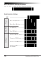
General Features ............................................................................................ 80
Good Read Beeper Settings ................................................................... 80
Read Verification ..................................................................................... 82
Low Power Mode .................................................................................... 85
Debug Mode ........................................................................................... 86
AutoSense® Stand Mode ....................................................................... 86
Appendix A
Additional Information -------------------------------------------------------- 87
Host Programming .......................................................................................... 87
Creating MultiFunction Labels ........................................................................ 87
Need More Information? ................................................................................. 87
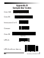
Appendix B
Sample Bar Codes -------------------------------------------------------------- 88
ii
QuickScan 6000/6000 Plus
Introduction
This manual contains instructions for changing interfaces and bar codes
for customizing the scanner's operation. Since the QuickScan 6000/6000 Plus
scanner contains software enhancements and characteristics that set it
apart from other scanners, it is recommended that this guide be used as
the sole source of programming labels and information (except for other
QuickScan 6000/6000 Plus product-specific publications).
The organization of this manual is intended to support a variety of users
while making it quick and easy to find the information you need. Look at
the descriptions that follow to find where to go from here.
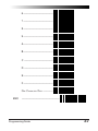
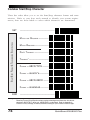
Understanding the Basics
If you do not regularly use bar code labels to configure (program)
scanners, it will be very helpful to read the introductory portions of this
manual prior to beginning your programming session. In addition to the
information that follows, information of specific interest to you is titled:
—
—
—
—
—
—
—
—
—
—
Integrating Peripherals with Host Systems
Changing Interfaces
Customizing Your Scanner Operation
Programming Overview
What is Programming Mode?
How to Program Using Bar codes
The Programming Session
Scanner Response When in Programming Mode
If You Make A Mistake
Where to Go From Here
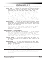
Integrating Peripherals With Host Systems
It's important to understand that the scanner must contain software and
hardware that supports a specific interface in order to use that interface.
The following pages describe interface hardware and list software interface groups available on current models.
Optimally, you'll want details about how your scanner was configured at
the factory before attempting to customize any settings. If you don't have
that information, contact your dealer for factory configuration information.
After determining the changes and/or additions you desire, locate the
programming labels and follow the related instructions in this manual to
adjust the scanner. Once you've completed these steps, you can begin
scanning.
Programming Guide
1
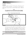
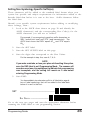
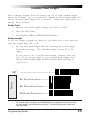
Changing Interfaces
To change a scanner's interface…
Hardware
If necessary, replace the scanner's interface cable to match the new host
terminal's connection requirements. To disconnect the cable from the
scanner, insert a .050” hex driver or bent paper clip into the CABLE RELEASE hole, and press down to unlock the cable connector. Reference
Figure 1.
NOTE
We recommend that you disconnect power before plugging/
unplugging cables to avoid any possibility of equipment damage.
Figure 1. Disconnecting the Interface Cable`
Paper Clip
Cable Release
Interface
Connector
Software
2
1.
Verify that your scanner supports the desired interface1. The list
on the following page indicates interfaces available at the time of
this writing. Your scanner comes equipped from the factory with
the ability to connect and communicate with at least two major
interface types. For example, OCIA/RS-232 and Keyboard Wedge/
Wand Emulation are two common pairings. Contact your nearest service
depot if you don't know your scanner's interface group, or need to have the
scanner altered to change to another I/F group.
1
Contact your dealer if your desired interface is not listed. Interface group definitions
are subject to change without notice.
QuickScan 6000/6000 Plus
OCIA
•
•
•
•
Datalogic OCIA
NCR 8-Bit OCIA
SNI OCIA
NCR 9-Bit OCIA
RS-232
• Datalogic RS-232
• SNI RS-232
IBM
• IBM 4683/84, 4693/94 Port 5B
• 4682/92 Port E
• IBM 4683/84, 4693/94 Port 9A, 9B, 9C, 9E
Wand Emulation
Keyboard Wedge
• I/F Type A — PC/XT w/foreign keyboard
• I/F Type B — AT, PS/2 25-286, 30-286, 50, 50Z, 60, 70, 80, 90 &
95 w/foreign keyboard
• I/F Type C — PS/2 25 and 30 w/foreign keyboard
• I/F Type D — PC/XT w/US keyboard
• I/F Type E — AT, PS/2 25-286, 30-286, 50, 50Z, 60, 70, 80, 90 &
95 w/US keyboard
• I/F Type F — PS/2 25 and 30 w/US keyboard
• I/F Type G — IBM 3xxx w/122 keyboard (QuickScan 6000 Plus ONLY)
• I/F Type H — IBM 3xxx w/102 keyboard (QuickScan 6000 Plus ONLY)
• I/F Type I — PS/55 5530T w/104 keyboard (QuickScan 6000 Plus ONLY)
• I/F Type J NEC 9801 (QuickScan 6000 Plus ONLY)
2.
Turn to the appropriate page in this manual and enable the
desired interface or interface sub-type by scanning its programming bar code. These interface/interface sub-type
selection bar codes are located at the beginning of each of
these sections of the manual: IBM, OCIA, Wand Emulation,
RS-232, and Keyboard Wedge. This will enable the software
for the new interface and disable the 'old' interface software.
Once enabled, the new interface becomes the default interface that is active whenever power is applied to the scanner.
3.
Scan a bar code to verify that the scanner communicates
correctly with the host system. Some sample bar codes are
provided on the last pages of this manual. If any changes to
the scanner's factory settings are needed, use the instructions
titled, Customizing Your Scanner Operation.
Programming Guide
3
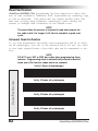
Customizing Your Scanner Operation
When enabling a new interface, it may be necessary to modify the original factory
settings to match your specific host system's communication and symbology
requirements. Check with your system administrator to identify your host system's
specific interface requirements to ensure that they match the new interface you've
selected. Also, the scanner's operational features, such as speaker volume, can be
customized to match your unique requirements.
1.
Use the labels in this manual to modify the standard configuration to
match your specific interface requirements or user preference.
NOTE
Ensure that your planned modifications are compatible with the
current interface. For example, baud rate selections are only valid
in the RS-232 interface. The scanner will sound an error tone (six
rapid beeps) when scanning programming labels for features
invalid to the current interface.
2.
Enable any additional symbologies as required and exit
Programming Mode.
3.
Scan a regular bar code label and verify that the scanner and
host communicate correctly.
4.
You have completed the factory settings change procedure.
If you experience difficulties, have questions or require additional information, contact your local distributor using the listings located on the
back cover of this guide.
Programming Overview
This section describes how to set the scanner's programmable features. These
4
QuickScan 6000/6000 Plus
features can be configured using the bar code labels contained in this manual or by
using commands sent from the host. Refer to Appendix A, Additional Information,
for host programming details. If you program the scanner using these bar codes, the
scanner stores the changes until reprogrammed.
What Is Programming Mode?
To change the scanner's programmed settings, it is necessary to place the
scanner in Programming Mode using the special SET label. This ensures
that the scanner only recognizes the special programming labels contained in this programming guide.
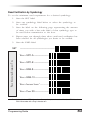
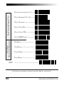
How To Program Using Bar Codes
The following pages contain special bar code labels that are used to
change or enable the scanner's programmable options. All programming
sessions follow this order, unless otherwise instructed:
1.
Scan the SET label at the top of the page. The scanner will
emit a 'good read' beep, indicating it has read the label.
2.
Scan the feature label(s) for the programmable options
you wish to enable. With few exceptions1, the scanner will
emit a triple beep each time you scan a valid programming
label. (Note that not all features are available for all interfaces and that the scanner will sound an error tone when
scanning programming labels for features invalid to the
current interface.)
3.
Scan the END label at the bottom of the page to complete
the programming session and exit Programming Mode. The
scanner will sound one 'good read' beep upon exiting
Programming Mode.
4.
Maintain a good record of all changes made to ensure that
you know if the original factory settings have been changed.
1
Some features, such as Minimum Label Length or Label ID, require you to select the length
by scanning a series of single-digit bar codes. A single 'good read' beep is sounded when
scanning these single digits in Programming Mode. Only the final required digit in the
sequence will produce a triple beep when scanned, indicating a successfully programmed
feature.
Programming Guide
5
The Programming Session
It is possible to program multiple features during a single programming
session (a programming session is defined as the period of time between
scanning the “set” label and scanning the “end” label). However, it is recommended
that sessions be limited to one feature, as it can be difficult to discover where an error
has been made, should you make a mistake in the programming sequence. Additionally, it can be confusing to determine which features may or may not have been
successfully set following such a session.
The scanner will not exit Programming Mode unless the END label is scanned.
Disconnecting power during Programming Mode, before scanning the END label,
will cause the scanner to forget any programming labels scanned during the current
programming session and will cause the scanner to return to its previous settings.
Scanner Response When In Programming Mode
As discussed earlier, Programming Mode is entered by scanning a SET
label. The green LED will flash continuously at 1Hz duty cycle while the
scanner is in Programming Mode. As long as it is in Programming Mode,
the scanner will not decode regular bar code labels and will only enable
features supported by the currently active interface.
Scanning regular (non-programming) bar code labels — the
scanner will reject the label, sounding an error tone (six rapid
beeps).
Scanning a valid programming label
a.
—
If the feature is supported by the active interface, the
scanner will sound three beeps.
b. If incorrect programming has been entered, the error tone
will be sounded (six rapid beeps). Additionally, when
programming a feature requiring you to scan single digits
to set a multi-digit number, such as Minimum Label
Length or Label ID, scanning the END label before
completing all input will result in an error tone and cause
the scanner to exit Programming Mode. Under these
circumstances, the current feature you were trying to set
is thrown out; any previous labels scanned during the
session will take effect.
6
QuickScan 6000/6000 Plus
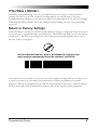
If You Make a Mistake...
If, during a programming session, you find that you are unsure of the scanner's
settings or wish to reset the scanner's configuration, use the Return to Factory
Settings label on this page to return the scanner's configuration to the factory settings.
Scanning this label will also reset any changes made during previous programming
sessions.
Return to Factory Settings
W
AR
NI
NG
Scan this label to return the scanner to the default settings configured at the factory for
your scanner’s original interface specifications. This label is typically used to return the
scanner to a “known” operating state when the present programming status is not
known, faulty, or suspect.
Use this label with caution, since it will disable ALL features that
may have been programmed since the scanner’s installation.
If you don't have a record of your site/system's original configuration, you may need
to call your nearest service depot for assistance to return the scanner to normal
function. Please be prepared to provide information about the store/chain, location,
POS system and other pertinent information about the scanner being repaired.
Programming Guide
7
Where To Go From Here
Programming is easy and straightforward if you follow these steps:
1.
If you are changing interfaces, first connect the scanner to the new host
using the new interface cable. Scan the interface enable bar code label1 .
2.
Scan any feature labels that are unique to the interface you are currently
programming. These interface specific programming labels immediately follow each interface selection label.
3.
Turn to the Symbology section if you are going to change any bar code
symbologies or modify any symbology related features.
4.
Turn to the General Features section of this guide if you wish to
change or modify any of the scanner's other features.
Once the necessary changes have been made, and you have scanned the END label,
you are ready to scan.
1
8
This step is not necessary for QuickScan 6000 Plus scanners, unless you require a
specific interface sub-type such as SNI OCIA or IBM sub-type 4682/92 Port E.
Interface software is automatically selected when the QuickScan 6000 Plus hardware
connection (via a new interface cable) is made.
QuickScan 6000/6000 Plus
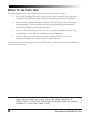
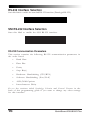
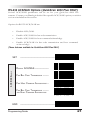
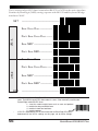
IBM 4683/84 • 4693/94 Port 5B Interface Selection
Scan this label to enable the IBM 468x Port 5B interface.
IBM 4683/84 • 4693/94 Port 5B Settings
Data Format: Send As Code 39 — converts bar code data (UPC/EAN,
add-ons, Code 93, Codabar, MSI/Plessey and Code 128) into Code 39
format before sending the data to the host.
These settings are for IBM 4683/84 • 4693/94 Port 5B interface ONLY.
Limit Command Set — is an option that causes the scanner to ignore
'enable scanner' and 'disable scanner' commands sent from the host.
Transmit Unsolicited Status1 — when enabled, this option causes the
scanner to transmit a status message to the host upon receipt of an "SNRM".
SET
---------------------------------------------SEND AS CODE 39 ----------------
DATA FORMAT
DON'T S END AS CODE 39 -------ENABLE LIMIT COMMAND SET ----DISABLE LIMIT COMMAND SET ----TRANSMIT UNSOLICITED STATUS --DON 'T TRANSMIT UNSOLICITED STATUS --END
1
----------------------------------------------
For this IBM interface, the setting for Unsolicited Status is normally Enabled.
Programming Guide
9
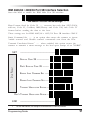
IBM 4683/84 • 4693/94 Port 9A, 9B, 9C, 9E I/F Selection
Scan this label to enable the IBM 468x/9x Port 9x interface.
IBM 4683/84 • 4693/94 Port 9A, 9B, 9C, 9E Settings
Data Format: Send As Code 39 — converts bar code data (UPC/EAN,
add-ons, Code 93, Codabar, MSI/Plessey and Code 128) into Code 39
format before sending the data to the host.
These settings are for IBM 4683/84 • 4693/94 Port 9A, 9B, 9C, 9E interface ONLY.
Limit Command Set — is an option that causes the scanner to ignore
'enable scanner' and 'disable scanner' commands sent from the host.
Transmit Unsolicited Status1 — when enabled, this option causes the
scanner to transmit a status message to the host upon receipt of an
"SNRM".
SET
---------------------------------------------SEND AS CODE 39 ----------------
DATA F ORMAT
DON 'T S END AS CODE 39 -------ENABLE LIMIT COMMAND SET ----DISABLE LIMIT COMMAND SET ----TRANSMIT UNSOLICITED S TATUS --DON' T TRANSMIT UNSOLICITED STATUS --END
1
10
----------------------------------------------
For this IBM interface, the setting for Unsolicited Status is normally Disabled.
QuickScan 6000/6000 Plus
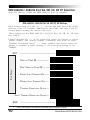
IBM 4682/92 Port E Interface Selection
Scan this label to enable the IBM 468x/9x Port E interface.
IBM 4682/92 Port E Settings
Data Format: Send As Code 39 — converts bar code data (UPC/EAN,
add-ons, Code 93, Codabar, MSI/Plessey and Code 128) into Code 39
format before sending the data to the host.
These settings are for IBM 4682/92 Port E interface ONLY.
Limit Command Set — is an option that causes the scanner to ignore
'enable scanner' and 'disable scanner' commands sent from the host.
Transmit Unsolicited Status1 — when enabled, this option causes the scanner
to transmit a status message to the host upon receipt of an "SNRM".
SET
---------------------------------------------SEND AS CODE 39 ----------------
DATA F ORMAT
DON 'T S END AS CODE 39 -------ENABLE LIMIT COMMAND SET ----DISABLE LIMIT COMMAND SET ----TRANSMIT UNSOLICITED S TATUS --DON 'T TRANSMIT UNSOLICITED STATUS --END
1
----------------------------------------------
For this IBM interface, the setting for Unsolicited Status is normally Disabled.
Programming Guide
11
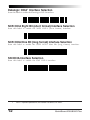
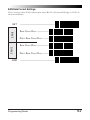
Datalogic OCIA1 Interface Selection
Scan this label to enable the Datalogic OCIA interface.
NCR OCIA Eight Bit (short format) Interface Selection
Scan this label to enable the NCR OCIA (short format) interface.
NCR OCIA Nine Bit (long format) Interface Selection
Scan this label to enable the NCR OCIA Nine Bit (long format) interface.
SNI OCIA Interface Selection
Scan this label to enable the SNI OCIA interface.
1
12
NOTE: In previous publications, this interface was termed, "SP OCIA".
QuickScan 6000/6000 Plus
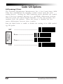
OCIA Options
Use these labels to change the settings as desired.
descriptions explain each selection.
The following brief
Beep if Not on File — when enabled requires the scanner to
beep when a label is scanned that is not on file.
Host Commands — when enabled allows the scanner to
accept commands directly from the host.
Intercharacter Delay — refers to a pause, if any, between
each character before being sent to the host. This time delay is
used to control the flow of data from the scanner, but it should
not be required for most applications. When enabled, OCIA
intercharacter delay is set at 70µs.
BEEP IF
NOT ON FILE
ENABLE -----------------------------
HOST
COMMANDS
----------------------------------------------
ENABLE -----------------------------
INTERCHARACTER
DELAY
SET
ENABLE -----------------------------
END
DISABLE -----------------------------
DISABLE -----------------------------
DISABLE --------------------------------------------------------------------------
Programming Guide
13
Wand Emulation Interface Selection
Scan this label to enable the Wand Emulation interface.
Wand Emulation Settings
POLARITY
SET
---------------------------------------------SPACE L OW, BAR HIGH -----------
SIGNAL SPEED
SPACE HIGH, BAR LOW ----------LOW (660 µS) -------------------HIGH (330 µS ) --------------------
DATA F ORMAT
TRANSMIT IN NORMAL F ORMAT ----TRANSMIT IN C39 FORMAT -------TRANSMIT IN C128 FORMAT -----TRANSMIT IN C39 ----------------FULL ASCII
14
QuickScan 6000/6000 Plus
I DLE STATE
TRANSMIT A NOISE
PATTERN B EFORE
LABEL TRANSMISSION
TRANSMIT C128
FUNCTION CHAR'S
END
LOW --------------------------------HIGH -------------------------------TRANSMIT PRE-NOISE ------------DON'T TRANSMIT PRE-NOISE -----ENABLE ----------------------------DISABLE --------------------------------------------------------------------------
Go to the sections titled Symbology Selection and General Features in the
back of this programming guide if you want to change any other settings
for this interface.
Programming Guide
15
RS-232 Interface Selection
Scan this label to enable the standard RS-232 interface (Datalogic RS-232).
SNI RS-232 Interface Selection
Scan this label to enable the SNI RS-232 interface.
RS-232 Communication Parameters
This section contains the following RS-232 communication parameters in
the order listed:
•
Baud Rate
•
Data Bits
•
Parity
•
Stop Bit(s)
•
Hardware Handshaking (CTS/RTS)
•
Software Handshaking (Xon/Xoff)
•
ACK/NAK Options
•
Intercharacter Delay
Go to the sections titled Symbology Selection and General Features in the
back of this programming guide if you want to change any other settings
for this interface.
16
QuickScan 6000/6000 Plus
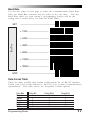
Baud Rate
Use the bar codes on this page to select the communications Baud Rate.
Only one Baud Rate selection may be active at any one time.
The last
Baud Rate label you scan during a programming session will be the
setting that is stored when you scan the END label.
SET
---------------------------------------------= 1200 ----------------------------
BAUD RATE
= 2400 ---------------------------= 4800 ---------------------------= 9600 ---------------------------= 19200 -------------------------= 38400 -------------------------END
----------------------------------------------
Data Format Table
There are many possible data format configurations for an RS-232 interface.
Check your host system manual to find out your system's communications
requirements. This table shows the acceptable format options.
Data Bits
Seven
Seven
Seven
Eight
Eight
Eight
Programming Guide
Start Bit
1
1
1
1
1
1
Parity Bit(s)
0
1
1
0
0
1
Stop Bit(s)
2
1
2
1
2
1
17
Data Format Settings
The bar codes on this page can be used to select the data format configuration needed to communicate with your system.
SET
---------------------------------------------NONE -------------------------------
PARITY
EVEN -------------------------------O DD -------------------------------MARK -------------------------------
DATA BITS
STOP B ITS
SPACE ------------------------------
END
18
O NE --------------------------------TWO -------------------------------SEVEN BITS -----------------------EIGHT B ITS ----------------------------------------------------------------------
QuickScan 6000/6000 Plus
Handshaking
Review your system documentation to identify handshaking requirements,
and use these labels to change the settings if required. The following brief
descriptions explain each selection.
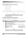
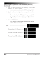
Hardware Control
CTS/RTS Flow Control — is hardware handshaking. The
scanner activates the RTS (Ready to Send) line when it is ready to
send data to the host. The scanner waits for an active Clear to
Send (CTS) signal from the host before transmitting data. If
hardware control is disabled, CTS/RTS communication will not
take place. If the host deactivates the CTS line during data transmission, the host will receive additional characters for no more
than 2msec 1.
CTS/RTS Flow Control
Data
Label Transmission
Disabled
Xmission
Label Transmission
Active
CTS
Inactive
CTS Scan Control — is also a hardware control. When scan
control is enabled, label transmission is disabled until CTS is
asserted and de-asserted.
CTS Scan Control
Data
Label 1
Label 1
Will not scan again
until toggle
Label 2
Disabled until
Assert
CTS
1
De-assert
Varies slightly depending upon baud rate selected.
Programming Guide
19
Software Control
XON/XOFF — this is software handshaking that allows the host to
control data transmission. If the host sends an XOFF command to
the scanner, the scanner will not send the bar code data until it
receives an XON command from the host. If the host sends the
XOFF command during data transmission, the host will receive
additional characters for no more than 2msec1.
NOTE
Hardware/software controls are mutually exclusive. Enable only one
of these features at a time, as enabling multiple controls can produce
unpredictable results.
ENABLE CTS/RTS F LOW CONTROL -ENABLE CTS SCAN CONTROL ---ENABLE X ON/ XOFF ---------------DISABLE XON/X OFF ----------------
END
1
20
---------------------------------------------DISABLE HARDWARE CONTROL -----
SOFTWRE CONTROL
HARDWARE CONTROL
SET
----------------------------------------------
Varies slightly depending upon baud rate selected.
QuickScan 6000/6000 Plus
RS-232 ACK/NAK Options (QuickScan 6000 Plus ONLY)
Several ACK/NAK parameters can be set for your QuickScan 6000 Plus
scanner. Contact your Datalogic dealer if the specific ACK/NAK option you wish to
set is not included in this section.
Options for RS-232 ACK/NAK are:
•
Disable ACK/NAK
•
Enable ACK/NAK for bar code transmission
•
Enable ACK/NAK for host command acknowledge
•
Enable ACK/NAK for bar code transmission and host command
acknowledge.
(These features available for QuickScan 6000 Plus ONLY)
SET
----------------------------------------------
ACK/NAK ENABLE
DISABLE ACK/NAK ------------------FOR BAR CODE TRANSMISSION -------FOR HOST COMMAND ACKNOWLEDGE -FOR BAR CODE TRANSMISSION -------AND H OST COMMAND A CKNOWLEDGE
END
----------------------------------------------
Programming Guide
21
Intercharacter Delay
Intercharacter Delay refers to the pause, if any, between each character
before it is sent to the host. This time delay is used to control the flow of
data from the scanner, but it should not be required for most applications.
Use these labels to select the desired Intercharacter Delay.
SET
---------------------------------------------= NONE ---------------------------= 10 MILLISECONDS ----------------
I NTERCHARACTER DELAY
= 20 MILLISECONDS ---------------= 30 MILLISECONDS ---------------= 40 MILLISECONDS ---------------= 50 MILLISECONDS ---------------= 60 MILLISECONDS ---------------= 70 MILLISECONDS ---------------= 80 MILLISECONDS ----------------
22
QuickScan 6000/6000 Plus
INTERCHARACTER
DELAY
Intercharacter Delay
(continued)
END
= 90 MILLISECONDS ---------------= 100 MILLISECONDS -----------------------------------------------------------
Programming Guide
23
This section contains the following PC Keyboard Wedge communication
parameters in the order listed:
Keyboard Wedge Communication Parameters
•
Interface Selection
•
Connect to Laptop
•
Caps lock Settings
•
Country modes
•
Intercharacter Delay
Go to the sections titled Symbology Selection and General Features in the
back of this programming guide if you want to change any other settings.
NOTE
If the transmission parameters are configured such that a label
results in no actual data to send, the label will be accepted, beeped,
and no data transmitted.
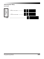
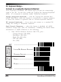
PC Keyboard Wedge Interface Selection
The scanner supports ten1 PC Keyboard Wedge interfaces. The table
below defines the different interface selections.
I/F Type
A
B
C
D
E
F
G
H
I
J
PCs Supported
PC/XT w/Alternate Key Encoding
AT, PS/2 25-286, 30-286, 50, 50Z, 60, 70, 80, 90 & 95 w/Alternate Key Encoding
PS/2 25 and 30 w/Alternate Key Encoding
PC/XT w/Standard Key Encoding
AT, PS/2 25-286, 30-286, 50, 50Z, 60, 70, 80, 90 & 95 w/Standard Key Encoding
PS/2 25 and 30 w/Standard Key Encoding
IBM 3xxx w/122 keyboard
(QuickScan 6000 Plus ONLY)
IBM 3xxx w/102 keyboard
(QuickScan 6000 Plus ONLY)
PS/55 5530T w/104 keyboard
(QuickScan 6000 Plus ONLY)
NEC 9801
(QuickScan 6000 Plus ONLY)
NOTE
We recommend that you disconnect power before plugging/
unplugging cables to avoid any possibility of equipment damage.
24
QuickScan 6000/6000 Plus
PC Keyboard Wedge Interface Selection—continued
The scanner supports ten1 PC Keyboard Wedge interfaces. The table
below defines the different interface selections.
SET
---------------------------------------------A-----------------------------------B-----------------------------------C -----------------------------------
I NTERFACE (I/F) TYPE
(SEE TABLE ON PREVIOUS PAGE)
D ----------------------------------E-----------------------------------F -----------------------------------G ----------------------------------H ----------------------------------I ------------------------------------J ------------------------------------
END
1
----------------------------------------------
Keyboard Wedge interfaces G through J are only supported by the QuickScan 6000 Plus
scanner.
Programming Guide
25
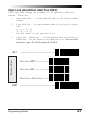
PC Keyboard Wedge –
Connect to a Laptop/No Keyboard Attached
If no keyboard is attached, the scanner must provide the acknowledge
signal to the PC. In this case, enable the "Laptop/No External Keyboard"
mode. If a keyboard is attached, enable "Keyboard Attached".
Laptop (integrated keyboard) — scan the "Laptop/No External Keyboard" label below when the scanner is connected to a laptop computer
or when the scanner is operated with no external keyboard attached.
PC (external keyboard) — if you move the scanner to a standard PC,
change the setting to "Keyboard Attached".
Send Control Characters — when this feature is disabled, all ASCII
characters except NUL (00h) are transmitted. Enabling this feature limits
transmission of ASCII characters to the following:
•
Only ASCII characters between 20h..127h, plus…
- Carriage Return (CR=0Dh)
- BackSpace (BS=08h)
- Right Tab (HT=09h)
- Left Tab (0Bh)
- Esc (1Bh)
SEND CONTROL
CHARACTERS
CONNECT TO
LAPTOP OR PC
SET
END
26
---------------------------------------------LAPTOP/NO EXTERNAL K EYBOARD KEYBOARD A TTACHED -------------ENABLE ----------------------------DISABLE --------------------------------------------------------------------------
QuickScan 6000/6000 Plus
Caps Lock (QuickScan 6000 Plus ONLY)
Three caps lock settings are available for the QuickScan 6000 Plus
scanner. These are:
•
Caps Lock Off — to send character data (to the host)in normal
format.
•
Caps Lock On — to send character data (to the host) in reverse
case:
(a…z) = (A…Z)
(A…Z) = (a…z)
Use this feature if your caps lock is on.
•
Caps Lock = Shift-Lock — to send character data (to the host) in
shifted case. Use this feature if your shift lock is on. For use with
interface type G (122-keyboard) ONLY.
CAPS LOCK OPTIONS
SET
----------------------------------------------
CAPS LOCK OFF ------------------
CAPS LOCK ON -------------------
CAPS LOCK = SHIFT-L OCK -------END
----------------------------------------------
Programming Guide
27
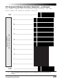
Country Mode (QuickScan 6000 Plus ONLY)
The following country/languages can be selected for the QuickScan 6000
Plus scanner when configured for I/F Type E only:
•
•
•
•
USA
Belgium
Britain
Denmark
SET
• France
• Germany
• Italy
• Norway
• Portugal
• Japanese 106-Key
• Spain
• Sweden
• Switzerland
---------------------------------------------USA ------------------------------BELGIUM ----------------------------
COUNTRY MODE
BRITAIN ----------------------------DENMARK --------------------------FRANCE ----------------------------G ERMANY --------------------------ITALY -------------------------------NORWAY ---------------------------PORTUGAL --------------------------
28
QuickScan 6000/6000 Plus
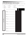
Country Mode (QuickScan 6000 Plus ONLY)—continued
COUNTRY MODE
SPAIN ------------------------------SWEDEN ---------------------------SWITZERLAND ----------------------JAPANESE 106-KEY --------------END
----------------------------------------------
Programming Guide
29
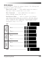
Intercharacter Delay
Intercharacter Delay refers to the pause, if any, between each character
before it is sent to the host. This time delay is used to control the flow of
data from the scanner, but it should not be required for most applications.
Use these labels to select the desired Intercharacter Delay.
SET
---------------------------------------------= NONE ---------------------------= 5 MILLISECONDS -----------------= 10 MILLISECONDS ----------------
INTERCHARACTER DELAY
= 15 MILLISECONDS ---------------= 20 MILLISECONDS ---------------= 25 MILLISECONDS ---------------= 30 MILLISECONDS ---------------= 35 MILLISECONDS ---------------= 40 MILLISECONDS ---------------= 45 MILLISECONDS ---------------= 50 MILLISECONDS ----------------
30
QuickScan 6000/6000 Plus
Intercharacter Delay—continued
= 55 MILLISECONDS ---------------= 60 MILLISECONDS ---------------= 65 MILLISECONDS ----------------
INTERCHARACTER DELAY
= 70 MILLISECONDS ---------------= 75 MILLISECONDS ---------------= 80 MILLISECONDS ---------------= 85 MILLISECONDS ---------------= 90 MILLISECONDS ---------------= 95 MILLISECONDS ---------------= 99 MILLISECONDS ---------------END
----------------------------------------------
Programming Guide
31
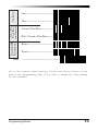
Label Transmit Format Configuration Items
(RS-232 and Keyboard Wedge Interfaces Only)
If you need to send information in addition to label data, the scanner can
be configured to transmit prefixes and/or suffixes as well as symbology
specific identifier characters (Label I.D.).
Prefix & Suffix
As the examples below show, none, one or two symbology specific ASCII
characters can be added to the beginning of label in addition to multiple
prefix and suffix characters.
NOTE
Using this feature requires a thorough understanding
of your specific system requirements.
The options available using this feature are:
•
Symbology specific (0 - 2) characters + label data
PP + label data
•
Non-symbology specific characters (1-2) as a prefix + label
data
CpCp + label data
•
Label data + non-symbology specific characters (0-2) as a
suffix
label data + CsCs
•
Non-symbology specific characters (1-2) as a prefix + symbology specific characters (0-2) + label data
CpCp + PP + label data
•
Symbology specific characters (0-2) + label data + nonsymbology specific characters (1-2) as a suffix
PP + label data + CsCs
32
QuickScan 6000/6000 Plus
•
Non-symbology specific characters (1-2) as a prefix + label
data + non-symbology specific characters (1-2) as a suffix
CpCp + label data + CsCs
•
Non-symbology specific characters (1-2) as a prefix + symbology specific characters (0-2) + label data + non-symbology
specific characters (1-2) as a suffix
CpCp + PP + label data + CsCs
•
Non-symbology specific characters (1-2) as a prefix + label
data + symbology specific characters + non-symbology
specific characters used as suffixes.
CpCp + label data + PP + CsCs
PP = symbology specific characters (Label I.D.)
CpCp = non-symbology specific ASCII characters used as prefixes
CsCs = non-symbology specific ASCII characters used as suffixes
Programming Guide
33
Non-Symbology Specific Items
Setting Non-Symbology Specific Prefix(es)
These characters will be added to the standard label format when your
host system has specific and unique requirements for information added
to the barcode label data before it is sent to the host. Identify your
specific system requirements before adding or modifying these settings,
then...
1.
Look at the ASCII chart shown on page 38 and identify the
ASCII character(s) and the corresponding Hex Code(s) for the
ASCII characters you will use as prefixes.
For example, if you are going to send two prefix characters as
'STX' (start transmit) and 'SP' (Space). The ASCII chart shows
that 'STX' equals 02 hex and 'SP' equals 20hex.
2.
Scan the SET label.
3.
Scan the SET PREFIX label on this page.
4.
Scan the digits that correspond to the Hex Values.
For the example in step four, scan 0, 2, 2, 0.
NOTE
If you make a mistake, or lose your place while setting this option,
scan the END label to exit Programming Mode. The scanner will
sound an error tone (six rapid beeps) to indicate that programming
was incomplete, and the setting will remain as it was before
entering Programming Mode.
5.
Scan END.
You have added a two character prefix to all label data, regardless of label symbology, that will be added to the label data
before it is sent to the host.
SET
---------------------------------------------SET P REFIX ------------------------
Go to the second page following this and scan the appropriate characters
before scanning the END label to exit programming session.
34
QuickScan 6000/6000 Plus
Setting Non-Symbology Specific Suffix(es)
These characters will be added to the standard label format when your
system has specific and unique requirements for information added to the
barcode label data before it is sent to the host. Suffix characters follow
the label data.
Identify your specific system requirements before adding or modifying
these settings, then...
1.
Look at the ASCII chart shown on page 38 and identify the
ASCII character(s) and the corresponding Hex Code(s) for the
ASCII characters you will use as suffixes.
For example, if you are going to send two suffix characters as
'BEL' (sound host tone) and 'ETX' (end transmission). The
ASCII chart shows that 'BEL' equals 07 hex and 'ETX' equals
03hex.
2.
Scan the SET label.
3.
Scan the SET SUFFIX label on this page.
4.
Scan the digits that correspond to the Hex Values.
For the example in step five, scan 0, 7, 0, 3.
NOTE
If you make a mistake, or lose your place while setting this option,
scan the END label to exit Programming Mode. The scanner will
sound an error tone (six rapid beeps) to indicate that programming
was incomplete, and the setting will remain as it was before
entering Programming Mode.
5.
Scan END.
You have added a two character suffix to all label data, regardless of label symbology, that will be added to the label data
before it is sent to the host.
SET
---------------------------------------------SET S UFFIX ------------------------
Go to the next two pages and scan the appropriate characters before
scanning the END label to exit programming session.
Programming Guide
35
Setting A Single Character Prefix or Suffix
To set one ASCII character as a prefix or suffix, follow steps one through
four on the previous two pages (select prefix or suffix), then...
1.
Scan the two digit Hex Code for that character.
(e.g. 03, 8F, ...FF)
NOTE
If you make a mistake, or lose your place while setting this option,
scan the END label to exit Programming Mode. The scanner will
sound an error tone (six rapid beeps) to indicate that programming
was incomplete, and the setting will remain as it was before
entering Programming Mode.
2.
Scan the ONE CHARACTER ONLY label on the following
page.
3.
Scan the END label.
You have set a single character prefix or suffix.
Setting Prefix and/or Suffix Characters
NOTE
You must scan the SET label and either the SET PREFIX or SET
SUFFIX label before using the labels on this page.
0 -----------------------------------1 -----------------------------------2 -----------------------------------3 -----------------------------------4 -----------------------------------5 ------------------------------------
36
QuickScan 6000/6000 Plus
6 -----------------------------------7 -----------------------------------8 -----------------------------------9 -----------------------------------A-----------------------------------B-----------------------------------C ----------------------------------D ----------------------------------E-----------------------------------F -----------------------------------ONE CHARACTER ONLY -----------END
----------------------------------------------
Programming Guide
37
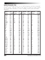
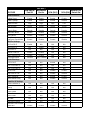
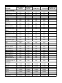
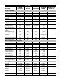
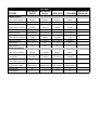
ASCII Character Set
The table on this page shows a set of ASCII characters and their corresponding Hex Values. The Hex Values in this table are needed for setting symbology specific label identifiers, as well as enabling custom prefix and suffix
characters.
ASCII
Hex
ASCII
Hex
ASCII
Hex
ASCII
Hex
Char
Value
Char
Value
Char
Value
Char
Value
nul
soh
stx
etx
eot
enq
ack
bel
bs
ht
lf
vt
ff
cr
so
si
dle
dc1
dc2
dc3
dc4
nak
syn
etb
can
em
sub
esc
00
01
02
03
04
05
06
07
08
09
0A
0B
0C
0D
0E
0F
10
11
12
13
14
15
16
17
18
19
1A
1B
SP
20
21
22
23
24
25
26
27
28
29
2A
2B
2C
2D
2E
2F
30
31
32
33
34
35
36
37
38
39
3A
3B
@
A
B
C
D
E
F
G
H
I
J
K
L
M
N
O
P
Q
R
S
T
U
V
W
X
Y
Z
[
40
41
42
43
44
45
46
47
48
49
4A
4B
4C
4D
4E
4F
50
51
52
53
54
55
56
57
58
59
5A
5B
‘
a
b
c
d
e
f
g
h
i
j
k
l
m
n
o
p
q
r
s
t
u
v
w
x
y
z
{
38
!
“
#
$
%
&
‘
(
)
*
+
‘
.
/
0
1
2
3
4
5
6
7
8
9
:
;
60
61
62
63
64
65
66
67
68
69
6A
6B
6C
6D
6E
6F
70
71
72
73
74
75
76
77
78
79
7A
7B
QuickScan 6000/6000 Plus
Symbology-Specific Label I.D.
Setting Symbology-Specific Label Identifiers (Label I.D.)
Symbology-specific label identifiers comprise one or two ASCII characters
that can precede or follow barcode label data as it is transmitted to the
host. The host uses these characters as a means of distinguishing between symbologies.
Industry standards have been established for symbology-specific label
identifiers, and are listed in the table below. Most scanners will have
factory default identifiers preset to these standards.
Table 1. Industry Standard Label Identifiers (all are prefixes)
UPC-A ------------------------------ 'A'
UPC-E ------------------------------ 'E'
EAN-8 ---------------------------- 'FF'
EAN-13 ----------------------------- 'F'
UPC-A (2 add-on) -------------- 'A'
UPC-A (5 Add-on) -------------- 'A'
UPC-A (8 Add-on) --------------- 'A'
UPC-E (2 add-on) -------------- 'E'
UPC-E (5 Add-on) -------------- 'E'
UPC-E (8 Add-on) --------------- 'E'
EAN-8 (2 add-on) ------------- 'FF'
EAN-8 (5 Add-on) ------------ 'FF'
EAN-8 (8 Add-on) ------------- 'FF'
EAN-13 (2 add-on) ------------- 'F'
EAN-13 (5 Add-on) ------------- 'F'
EAN-13 (8 Add-on) -------------- 'F'
Code 39 ----------------------------- '*'
Codabar --------------------------- '%'
Interleaved.2 of 5 ---------------- 'i'
Code 93 ---------------------------- '&'
Code 128 -------------------------- '#'
MSI/Plessey --------------------- '@'
To set symbology-specific label identifiers:
1.
Look at the ASCII chart shown on the previous page and
identify the ASCII character(s) and the corresponding Hex
Code(s) for the ASCII characters you will use as identifiers.
You will also need to determine whether the character(s) will
need to be sent as a prefix or a suffix.
For example: You need to change the label identifier prefix for
UPC-A to 'A1'.
2.
Scan the SET label below.
3.
Scan either the TRANSMIT LABEL I.D. AS PREFIX or TRANSMIT LABEL I.D. AS SUFFIX, depending on your requirements.
For our example, the 'transmit as prefix' label would be scanned.
Programming Guide
39
Setting Symbology Specific Label Identifiers (Label I.D.)
(Continued)
4.
Scan the label representing the symbology whose label
identifier you wish to modify.
In our example, we would scan the 'UPC-A' symbology label.
5.
Identify and scan the digits that correspond to the Hex
Values.
The hex values from the ASCII chart that correspond to 'A1'
from our example are as follows: 41 hex = 'A', and
31 hex = '1'. Thus, we would scan digit programming labels in this
order: 4, 1, 3, 1.
6.
Scan the END label.
In our example, you have changed the default label identifier
prefix for UPC-A from 'A' to 'A1'.
SET
---------------------------------------------DISABLE LABEL I.D. C ONTROL ------TRANSMIT LABEL I.D. AS P REFIX ----TRANSMIT LABEL I.D. AS S UFFIX -----
40
QuickScan 6000/6000 Plus
Label I.D. Symbology Selection
UPC-A ---------------------------UPC-A W/2 DIGIT ADD-ON -------UPC-A W/5 DIGIT ADD-ON --------
SET S YMBOLOGY SPECIFIC LABEL IDENTIFIER FOR:
UPC-A W/C128 ADD-ON -------UPC-E ---------------------------UPC-E W/2 DIGIT ADD-ON -------UPC-E W/5 DIGIT ADD-ON -------UPC-E W/C128 ADD-ON -------EAN-8 ---------------------------EAN-8 W/2 DIGIT ADD-ON -------EAN-8 W/5 DIGIT ADD-ON -------EAN-8 W/C128 ADD-ON -------EAN-13 ---------------------------
Programming Guide
41
Label I.D. Symbology Selection
(Continued)
EAN-13 W/2 DIGIT ADD-ON ------
SET SYMBOLOGY SPECIFIC LABEL IDENTIFIER FOR:
EAN-13 W/5 DIGIT ADD-ON -----EAN-13 W/C128 ADD-ON ------CODE 39 --------------------------CODABAR --------------------------I NTERLEAVED 2 OF 5 --------------STANDARD 2 OF 5 ----------------CODE 93 --------------------------CODE 128 ------------------------MSI/PLESSEY ---------------------END
42
----------------------------------------------
QuickScan 6000/6000 Plus
How to Set Single Character Label I.D.
If you only want a single character identifier, follow this modified procedure for setting label identifier.
1.
Look at the ASCII chart shown on page 38 and identify the
ASCII character and the corresponding Hex Code for the
ASCII character you will use as the symbology specific
identifier.
2.
Scan the SET label.
3.
Scan the label identifier label for the symbology identifier that
you are going to change.
As an example, assume that you want to change the label
identifier for EAN-8 from the default setting FF to the ASCII
value 8. Scan the Set Symbology Specific Label Identifier
barcode for EAN-8.
5.
Identify the hex value that correspond to the ASCII character.
In this example '8' equals 38 hex.
Simply follow the hex value for '8' (38hex) with the One Character
Only label. This tells the scanner that '8' is a single digit label
identifier.
6.
Scan the barcodes values.
For the example in step five, scan 3, 8, One Character Only on
the following two pages.
NOTE
If you make a mistake, or lose your place while setting this option,
scan the END label to exit Programming Mode. The scanner will
sound an error tone (six rapid beeps) to indicate that programming
was incomplete, and the setting will remain as it was before
entering Programming Mode.
7.
Scan the END label.
You have changed the default label identifier for EAN-8 from
'FF' to '8'.
Programming Guide
43
Disabling Label I.D. for a Specific Symbology
This procedure is the same as setting a single character symbology
identifier, except you should scan two zeros and the One Character Only
labels before scanning the END label.
Symbology Specific Label Identifiers Characters
Use the labels on this page to change or modify symbology identifiers.
0 -----------------------------------1 -----------------------------------2 -----------------------------------3 -----------------------------------4 -----------------------------------5 -----------------------------------6 -----------------------------------7 -----------------------------------8 -----------------------------------9 ------------------------------------
44
QuickScan 6000/6000 Plus
A-----------------------------------B-----------------------------------C ----------------------------------D ----------------------------------E-----------------------------------F -----------------------------------ONE CHARACTER ONLY -----------END
----------------------------------------------
Programming Guide
45
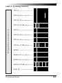
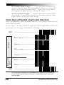
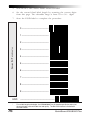
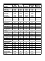
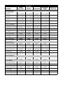
Symbologies
Symbology selection (bar code type) determines which symbologies the scanner will
decode. The chart below shows the symbologies that are supported by each interface.
Once you have identified the symbologies you wish to enable, turn to the following
pages, enable those symbologies and set the data format options (e.g. check digit,
start/stop characters) required by your host system for each symbology type. You
must enable the symbology format options settings that are compatible with your
host system.
INTERFACE TYPE
UPC-A & E, EAN-8 & 13
UPC/EAN w/P2 Add-ons
UPC/EAN w/P5 Add-ons
UPC/EAN w/C128 Add-ons
Code 39
Code 39 Pharmacodes
Interleaved 2 of 5
Interleaved 2 of 5/IATA
Standard 2 of 5
Codabar
Code 93
Code 128
MSI/Plessey
The factory settings for each interface were chosen to meet the standard industry
requirements and in most cases you will not need to change the symbology format
settings. If you are unsure of your system requirements, test the scanner using the
factory settings before making any changes.
IBM Port 5B
IBM Port 9B
IBM Port E
NCA OCIA (8 bit)
NCA OCIA (9 bit)
Datalogic OCIA
SNI OCIA
Wand Emulation
RS-232
Keyboard Wedge
KEY
QuickScan 6000 and QuickScan 6000 Plus
QuickScan 6000 Plus
The symbology can be enabled through configuration item; however,
labels will not be decoded or transmitted by the interface.
{
46
QuickScan 6000/6000 Plus
Symbology Options Overview
Enable All Symbologies — allows the scanner to auto-discriminate between
all the symbologies in this list. Use this selection only if you must constantly
read a wide variety of symbologies. Turn to the following pages for
enabling additional symbology specific options.
Disable All Symbologies — disables all symbologies1. The scanner will only
recognize the programming labels contained in this manual while you are
in Programming Mode.
Enable UPC/EAN — tells the scanner to recognize UPC-A, UPC-E, EAN8, and EAN-13. If you enable this symbology, additional options for
symbology expansion and reading add-ons are available. Allows selection
of expansion and add-on options.
Enable Code 39 — selects Code 39 as an active symbology. Allows selection
of Check Digit, Start/Stop and Single Digit options.
PharmaCode 39 — is a symbology subset of Code 39. Enabling PharmaCode
39 selects this special Italian code as the active Code 39 symbology
(superceding standard Code 39 features).
NOTE
Standard Code 39 must be enabled before PharmaCode can be
enabled.
Enable Interleaved 2 of 5 — selects Interleaved 2 of 5 as an active
symbology. Allows change of Check Digit or label format (fixed
or variable length) options.
Enable Standard 2 of 5 — selects Standard 2 of 5 as an active
symbology. Options for this symbology are similar to Interleaved 2 of 5 features.
1
Code 128 is always active for the purpose of reading programming bar code labels; however,
the scanner does not transmit data to the host when in Programming Mode. Scanning the
DISABLE ALL SYMBOLOGIES label will disable Code 128 transmission to the host.
Programming Guide
47
IATA — is a special symbology subset of Standard 2 of 5. Enabling IATA
selects this custom code as the active Standard 2 of 5 symbology (superceding any other Standard 2 of 5 features).
NOTE
Standard 2 of 5 must be enabled before IATA can be enabled.
Enable Codabar — selects Codabar as an active symbology. Allows selection
of Check Digit, Start/Stop character and format, or label format (fixed or
variable length) options.
Enable Code 93 — selects Code 93 as an active symbology. The scanner is preset
to recognize all Code 93 bar codes that have between 2 and 50 characters.
Code 93 has no user-selectable options.
Enable Code 1281 — selects Code 128 as an active symbology. The scanner
is preset to recognize all Code 128 bar codes that have between 2 and 50
characters. Code 128 has no user selectable options.
Enable MSI/Plessey — selects MSI/Plessey as an active symbology. Allows
selection of Check Digit or label format (fixed or variable length) options.
Universal Symbology Selection
To set the scanner to read all symbologies, scan the ENABLE ALL SYMBOLOGIES bar code below.
NOTE
DO NOT scan SET or END bar codes when programming universal
symbology features. Programming mode is automatically entered
and exited when one of the two special bar codes below are
scanned.
Enable All Symbologies
Disable All Symbologies1
1
48
Code 128 is always active for the purpose of reading programming bar code labels;
however, the scanner does not transmit data to the host when in Programming Mode.
QuickScan 6000/6000 Plus
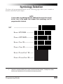
Symbology Selection
The bar code programming labels on the following pages allow you to enable or
disable individual symbologies.
NOTE
If you enable a symbology that has additional features that should
be set, turn to the pages that support that symbology and its
programmable features.
SET
---------------------------------------------ENABLE UPC/EAN -------------DISABLE UPC/EAN -------------ENABLE CODE 39-----------------DISABLE CODE 39 ----------------ENABLE P HARMACODE2 39 ------DISABLE PHARMACODE 39 --------
2
Code 39 must first be enabled for the scanner to read PharmaCode 39 labels. Enabling PharmaCode
39 will convert Code 39 data to PharmaCode format whenever possible.
Programming Guide
49
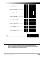
ENABLE I NTERLEAVED 2
OF
5 -----
DISABLE INTERLEAVED 2 OF 5 -----
ENABLE STANDARD 2
OF
5--------
DISABLE STANDARD 2
OF
5 -------
ENABLE IATA 3 --------------------
DISABLE IATA ---------------------
3
50
Standard 2 of 5 must first be enabled before IATA can be enabled; however, the scanner will not read
Standard 2 of 5 labels when IATA is enabled.
QuickScan 6000/6000 Plus
ENABLE CODABAR -----------------DISABLE C ODABAR -----------------ENABLE CODE 93-----------------DISABLE CODE 93 ----------------ENABLE CODE 128 ---------------DISABLE CODE 1284 -------------ENABLE MSI/P LESSEY -----------DISABLE MSI/PLESSEY ------------
END
4
----------------------------------------------
Code 128 is always active for the purpose of reading programming bar code labels. Scanning the
DISABLE ALL SYMBOLOGIES or the DISABLE CODE 128 labels disables Code 128 transmission to
the host (disables decoding of all C128 non-programming labels).
Programming Guide
51
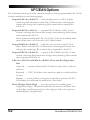
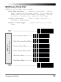
UPC/EAN Options
The information below provides a brief description of the programmable UPC/EAN
features included on the following pages.
Expand UPC-A to EAN-13 — adds a leading zero to a UPC-A label
which 'expands' the label to the EAN-13 data format. Selecting this
feature also changes the symbology ID to match those required for
EAN-13.
Expand UPC-E to UPC-A — expands UPC-E labels to UPC-A data
format. Selecting this feature also changes the symbology ID to match
those required for UPC-A.
If this feature and Expand UPC-A to EAN-13 are both enabled, label
data will be sent to the host in EAN-13 label format.
Expand EAN-8 to EAN-13 — adds five zeros in front of an EAN-8
label. Data is sent in EAN-13 data format. Selecting this feature also
changes the symbology ID to match those required for EAN-13.
Expand UPC-E to EAN-13 — expands UPC-E labels to EAN-13 data
format. Selecting this feature also changes the symbology ID to match
those required for EAN-13.
UPC-A or UPC-E and EAN-8 or EAN-13 Two and Five Digit AddOns
Optional — scanner will read UPC/EAN bar codes with or without
add-ons.
Required — UPC/EAN bar codes must have add-on or label will not
be read.
Disable — scanner will not recognize/read add-on portion of UPC/
EAN labels, but will read the main body of the label.
Price/Weight Check Digit — provides options for enabling price/
weight check digits. The feature includes selections for domestic four
or five digit, and European four or five digit, as well as the option to
disable the price/weight check.
52
QuickScan 6000/6000 Plus
UPC/EAN Expansion
Expand EAN-8 to EAN-13
•
Expand UPC-E to UPC-A
•
Expand UPC-E to EAN-13
SET
----------------------------------------------
EXPANSION
•
EXPAND1 ------------------------------------------------DON'T EXPAND ---------------------
EXPANSION
UPC-E TO UPC-A
Expand UPC-A to EAN-13
EXPAND1 ----------------------------
EXPANSION
EAN-8 TO EAN-13
UPC-E TO EAN-13
•
EXPAND1 ----------------------------
DON'T EXPAND ---------------------
DON'T EXPAND --------------------EXPAND1 -------------------------------------------------
EXPANSION
UPC-A TO EAN-13
Use these labels to enable or disable:
DON'T EXPAND ---------------------
END
1
----------------------------------------------
When any expansion feature is enabled, the transmission of the Prefix, Suffix, Check Digit
and Number System Digit (NSD) are controlled by your selections for the symbology
'expanded to' rather than the symbology 'expanded from'. For example, if you expand UPC-E
to UPC-A, settings for UPC-A determine how the scanner sends a bar code's contents.
Programming Guide
53
UPC/EAN Add-Ons
If you need to scan UPC or EAN labels that include add-on codes, the selections on
this page set the scanner's Add-on feature. Three add-on read modes are available:
optional, required and disabled.
Optional — the scanner will recognize UPC bar codes with or without
add-ons.
NOTE
Due to the structure of add-on codes, selecting the Optional
setting makes it impossible to ensure that the scanner will always
read the add-on portion of the label. Datalogic makes no guarantee, either written or implied, that scanners with optional add-on
decoding enabled will perform with the speed and accuracy required for any given application.
Required — the scanner will not recognize or decode any UPC/
EAN labels that do not contain an add-on segment.
Disabled — the scanner will not recognize or decode any addon segment of UPC/EAN labels. The scanner will read and
decode the standard UPC/EAN portion of the label.
TWO DIGIT & FIVE DIGIT
ADD-ONS
SET
END
---------------------------------------------O PTIONAL --------------------------REQUIRED --------------------------DISABLED ------------------------------------------------------------------------
C128 and Custom Add-Ons
A wide array of add-on options are available to streamline your installation to best advantage. Call your salesman or service provider for assistance in customizing your scanner's add-on capabilities to your own
unique specifications.
54
QuickScan 6000/6000 Plus
Price/Weight Check Digit
The price/weight check digit selections allow you to specify whether the scanner
should calculate an extra check digit based on a four or five-digit price/weight block
and compare it with the price/weight check digit contained in the bar code. If the
calculated check digit does not match the value of the check digit contained in the bar
code, the label will be rejected as invalid. Select domestic four or five digit, European
four or five digit, or disable the price/weight check.
SET
----------------------------------------------
PRICE/WEIGHT CHECK DIGIT
DISABLE PRICE/W EIGHT CHECK --ENABLE 4 DIGIT CHECK ----------ENABLE 5 DIGIT CHECK ----------ENABLE E URO 4 DIGIT CHECK ---ENABLE E URO 5 DIGIT CHECK ---END
----------------------------------------------
UPC Data Format Settings
Programming Guide
55
These settings affect UPC data format when RS-232 or OCIA is the active interface.
Number System Digit (NSD) settings operate with RS-232 and Keyboard Wedge
interfaces ONLY.
SET
---------------------------------------------SEND CHECK DIGIT ----------------
UPC-A
DON'T S END CHECK DIGIT -------SEND NSD1 ----------------------DON'T SEND NSD1 --------------SEND CHECK DIGIT 2 ---------------
UPC-E
DON'T SEND CHECK DIGIT 2 ------SEND NSD2 ----------------------DON'T SEND NSD2 --------------END
1
2
56
----------------------------------------------
NSD = Number System Digit. The NSD character is the character that precedes the UPC bar
code. The NSD for regular UPC-A bar codes is a zero. Other commonly used Number
System Digits used with UPC-A are:
2 - used for random weight items such as meat and produce
3 - used for the drug and health items
4 - used for in-store non-food items
5 - used for coupons
If UPC-E is expanded to UPC-A, the transmission of Check Digit (CD) and NSD will be
determined by the UPC-A settings on this page, not by these settings.
QuickScan 6000/6000 Plus
EAN Data Format Settings
These settings affect EAN data format when RS-232, Keyboard Wedge or OCIA is
the active interface.
EAN-8
SET
---------------------------------------------SEND CHECK DIGIT ----------------
EAN-13
DON'T S END CHECK DIGIT --------
END
SEND CHECK DIGIT ---------------DON'T S END CHECK DIGIT -----------------------------------------------------
Programming Guide
57
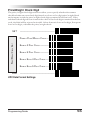
Code 39 Options
The Code 39 symbology has the following programmable features:
Check Digit — calculates the Check Digit to verify that the
Check Digit contained in the bar code label is correct. If you
enable this feature, your bar codes must contain a Check
Digit.
You may also choose to transmit or not transmit the Check
Digit independent of whether the Check Digit is calculated by
the scanner. If you choose to Transmit Check Digit, but not
calculate, the scanner sends the Check Digit encoded in the
bar code without verifying its accuracy. If you choose Don't
Transmit Check Digit, the scanner will remove the Check
Digit's contents before sending the bar code data to the host.
Start/Stop Characters — you can choose either Send or Don't
Send depending on your host's interface requirement.
Code 39 Full ASCII — enables or disable the ability to decode
Code 39 Full ASCII labels.
Code 39 Minimum Label Length — sets the minimum label
length required for Code 39 labels (not including the check
character). This feature is provided to ignore small label
segments, reducing the possibility that a portion of a good
label is incorrectly seen as an entire label.
58
QuickScan 6000/6000 Plus
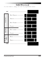
Code 39 (continued)
Use these labels to change the Code 39 programmable features.
SET
----------------------------------------------
CHECK DIGIT
DON 'T COMPUTE ------------------COMPUTE --------------------------DON'T TRANSMIT -------------------
CODE 39 FULL
ASCII
START/STOP
TRANSMIT ---------------------------
END
DON'T TRANSMIT -------------------TRANSMIT --------------------------ENABLE ----------------------------DISABLE --------------------------------------------------------------------------
Programming Guide
59
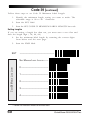
Code 39 (continued)
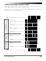
Follow these steps to set Code 39 Minimum Label Length:
1.
Identify the minimum length setting you want to make. The
selectable range is 00 to 48 * characters.
2.
Scan the SET label.
3.
Scan the SET CODE 39 MINIMUM LABEL LENGTH bar code.
Setting Lengths
If you are setting a length less than ten, you must scan a zero first and
then the length digit ( 04, 06, 08).
4.
Set the minimum label length by scanning the correct digits
from below and the next page.
5.
Scan the END label.
SET
----------------------------------------------
CODE 39 MINIMUM LABEL LENGTH
SET M INIMUM LABEL L ENGTH -----0 -----------------------------------1 -----------------------------------2 -----------------------------------3 -----------------------------------4 ------------------------------------
* The IBM POS Interface is limited to 32 character labels.
60
QuickScan 6000/6000 Plus
CODE 39 MINIMUM LABEL LENGTH
5 -----------------------------------6 -----------------------------------7 -----------------------------------8 -----------------------------------9 -----------------------------------END
----------------------------------------------
Programming Guide
61
Code 128 Options
AIM Symbology ID Prefix
The Automatic Identification Manufacturers, Inc. of the United States (AIM
USA) have standardized the reporting of data sources from bar code
reading devices. Sending the AIM symbology prefix identifies the symbology to the host terminal, allowing it to specifically differentiate between
UCC-128 (Code 128 with Function Character 1 in the first position) and
standard Code 128 symbols. When this feature is disabled, the host
cannot differentiate between these symbols.
Scan the labels below to enable or disable the sending of an AIM symbology ID prefix.
AIM SYMBOLOGY
ID PREFIX
SET
END
62
---------------------------------------------ENABLE ----------------------------DISABLE --------------------------------------------------------------------------
QuickScan 6000/6000 Plus
Interleaved 2 of 5
The Interleaved 2 of 5 symbology has the following programmable features:
Check Digit — calculates the Check Digit to verify that the Check
Digit contained in the bar code label is correct. If you enable
this feature, your bar codes must contain a Check Digit.
You may also choose to transmit or not transmit the Check
Digit independent of whether the Check Digit is calculated by
the scanner. The Transmit Check Digit will have no effect
unless the Compute Check Digit feature is enabled. If you
choose Don’t Compute Check Digit, the scanner sends the
Check Digit encoded in the bar code without verifying its
accuracy. If you choose both Compute Check Digit and Don't
Transmit Check Digit, the scanner will remove the Check Digit's
contents before sending the bar code data to the host.
Label Format — provides the selection between fixed or variable
length labels. If your application has labels with specific fixed
lengths, we recommend selecting fixed lengths to improve read
rate and avoid short reads.
You can select any valid number of digits for reading specific
length labels only. Read the following details for specific
Interleaved 2 of 5 limits.
Interleaved 2 of 5 Label Lengths
Interleaved 2 of 5 Minimum Label Length — sets the minimum
label length required for I 2/5 labels (not including the check
character). This feature is provided to ignore small label
segments, reducing the possibility that a portion of a good label
is incorrectly seen as an entire label.
Variable Length — if you select variable length, the scanner will
recognize labels with an even number of digits between 04 and
50 * digits.
Fixed Length — if you select fixed length, there are three labels
for programming your scanner to read either one or two fixed
lengths. The labels are:
•
Set First Fixed Length — use this label to instruct the
scanner that the next two programming labels you scan will
define the first fixed label length. This setting can be any even
number of digits between 02 and 50 * digits.
*
For variable length symbologies, the QS6000/6000 Plus will decode up to 50 characters, but
the actual length varies with label size and quality. The IBM POS interface is limited to 32
characters labels.
Programming Guide
63
•
Set Second Fixed Length — use this label to instruct the scanner
that the next two programming labels you scan will define the
second fixed label length. Again, this setting can be any even
number of digits between 02 and 50 * digits.
•
No Second Fixed Length — scan this label after setting the first
fixed length to instruct the scanner to recognize only the label
length chosen as the first fixed length.
Check Digit and Variable Length Label Selections
These programming labels determine whether you compute and send the
check digit contents.
If you want to set the scanner to read only fixed length labels, follow the
procedures on the pages immediately following.
SET
----------------------------------------------
CHECK DIGIT
DON'T COMPUTE ------------------COMPUTE --------------------------DON'T TRANSMIT -------------------
VARIBLE LENGTH
LABELS
TRANSMIT --------------------------ENABLE ----------------------------DISABLE -----------------------------
END
*
64
----------------------------------------------
For variable length symbologies, the QS6000/6000 Plus will decode up to 50 characters, but
the actual length varies with label size and quality. The IBM POS interface is limited to 32
characters labels.
QuickScan 6000/6000 Plus
Setting Interleaved 2 of 5 Fixed and Minimum Label Lengths
All interfaces that are shipped with the standard factory configuration are
set to read variable length labels. If you switch from variable to fixed
length labels (by disabling variable lengths on the previous page), the
default fixed label lengths are 14 digits and 8 digits. Follow the steps
below to change these defaults. All fixed length settings for Interleaved 2
of 5 must be an even number.
Set Fixed
1. Identify the fixed length settings you want to make.
2.
Scan the SET label.
3.
Scan the ENABLE FIRST FIXED bar code.
Setting Fixed Lengths
If you are setting a length less than ten, you must scan a zero first and
then the length digit ( 04, 06, 08).
4.
Set the first fixed label length by scanning the correct digits
from the next two pages.
If you need to set a second fixed length, continue with step
five. If you do not need to set a second fixed length scan the
NO SECOND FIXED LENGTH below and skip to step seven.
5.
Scan the SET SECOND FIXED label.
6.
Set the second fixed label length by scanning the correct
digits from this page.
7.
Scan the END label to complete the procedure.
Setting Minimum Label Length
1. Identify the minimum length setting you want to make. The
selectable range is 00 to 50 * characters.
2.
Scan the SET label.
3.
Scan the SET MINIMUM LABEL LENGTH bar code.
If you are setting a length less than ten, you must scan a zero first and
then the length digit ( 04, 06, 08).
4.
Set the minimum label length by scanning the correct digits
from the next two pages
5.
Scan the END label.
*
For variable length symbologies, the QS6000/6000 Plus will decode up to 50 characters, but
the actual length varies with label size and quality. The IBM POS interface is limited to 32
characters labels.
Programming Guide
65
SET
---------------------------------------------SET FIRST F IXED L ENGTH ---------
INTERLEAVED 2 OF 5 FIXED AND MINIMUM LABEL LENGTHS
SET S ECOND FIXED L ENGTH -----NO SECOND F IXED L ENGTH ------SET M INIMUM L ABEL L ENGTH -----0 -----------------------------------1 -----------------------------------2 -----------------------------------3 -----------------------------------4 -----------------------------------5 -----------------------------------6 -----------------------------------8 -----------------------------------END
66
---------------------------------------------QuickScan 6000/6000 Plus
Standard 2 of 5
The Standard 2 of 5 symbology has the following programmable features:
Check Digit — calculates the Check Digit to verify that the
Check Digit contained in the bar code label is correct. If you
enable this feature, your bar codes must contain a Check Digit.
You may also choose to transmit or not transmit the Check
Digit independent of whether the Check Digit is calculated by
the scanner. The Transmit Check Digit will have no effect
unless the Compute Check Digit feature is enabled. If you
choose Don’t Compute Check Digit, the scanner sends the
Check Digit encoded in the bar code without verifying its
accuracy. If you choose both Compute Check Digit and Don't
Transmit Check Digit, the scanner will remove the Check
Digit's contents before sending the bar code data to the host.
The Transmit Check Digit option has no effect unless the
Compute Check Digit option is enabled.
Label Format — provides the selection between fixed or
variable length labels. If your application has labels with
specific fixed lengths, we recommend selecting fixed lengths
to improve read rate and avoid short reads.
You can select any valid number of digits for reading specific
length labels only. Read the following details for specific
Standard 2 of 5 limits.
Standard 2 of 5 Label Lengths
Standard 2 of 5 Minimum Label Length — sets the minimum
label length required for Standard 2/5 labels (not including
the check character). This feature is provided to ignore small
label segments, reducing the possibility that a portion of a
good label is incorrectly seen as an entire label.
Variable Length — if you select variable length, the scanner will
recognize labels with a number of digits between 01 and 50 * digits.
Fixed Length — if you select fixed length, there are three labels
for programming your scanner to read either one or two fixed
lengths. The labels are:
•
Set First Fixed Length — use this label to instruct the scanner
that the next two programming labels you scan will define the
first fixed label length. This setting can be any number of digits
between 01 and 50 * digits.
*
For variable length symbologies, the QS6000/6000 Plus will decode up to 50 characters, but
the actual length varies with label size and quality. The IBM POS interface is limited to 32
characters labels.
Programming Guide
67
•
Set Second Fixed Length —
use this label to instruct the
scanner that the next two programming labels you scan will
define the second fixed label length. Again, this setting can be
any number of digits between 01 and 50 * digits.
•
No Second Fixed Length — scan this label after setting the first
fixed length to instruct the scanner to recognize only the label
length chosen as the first fixed length.
Check Digit and Variable Length Label Selections
These programming labels determine whether you compute and send the
check digit contents.
If you want to set the scanner to read only fixed length labels, follow the
procedures on the pages immediately following.
SET
----------------------------------------------
CHECK DIGIT
DON 'T COMPUTE --------------------
COMPUTE --------------------------DON'T TRANSMIT --------------------
VARIBLE LENGTH
LABELS
TRANSMIT --------------------------ENABLE ----------------------------DISABLE -----------------------------
END
*
68
----------------------------------------------
For variable length symbologies, the QS6000/6000 Plus will decode up to 50 characters, but
the actual length varies with label size and quality. The IBM POS interface is limited to 32
characters labels.
QuickScan 6000/6000 Plus
Setting Standard 2 of 5 Fixed and Minimum Label Lengths
All interfaces that are shipped with the standard factory configuration are
set to read variable length labels. If you switch from variable to fixed
length labels, the default fixed label lengths are 14 digits and 8 digits.
Follow the steps below to change these defaults.
Set Fixed
1. Identify the fixed length settings you want to make.
2.
Scan the SET label.
3.
Scan the ENABLE FIRST FIXED bar code.
Setting Fixed Lengths
If you are setting a length less than ten, you must scan a zero first and
then the length digit ( 04, 07, 08).
4.
Set the first fixed label length by scanning the correct digits
from the next two pages.
If you need to set a second fixed length, continue with step
five. If you do not need to set a second fixed length scan the
NO SECOND FIXED LENGTH below and skip to step seven.
5.
Scan the SET SECOND FIXED label.
6.
Set the second fixed label length by scanning the correct
digits from this page.
7.
Scan the END label to complete the procedure.
Setting Minimum Label Length
1. Identify the minimum length setting you want to make. The
selectable range is 01 to 50 * characters.
2.
Scan the SET label.
3.
Scan the SET MINIMUM LABEL LENGTH bar code.
If you are setting a length less than ten, you must scan a zero first and
then the length digit ( 04, 07, 08).
4.
Set the minimum label length by scanning the correct digits
from the next two pages.
5.
Scan the END label.
*
For variable length symbologies, the QS6000/6000 Plus will decode up to 50 characters, but
the actual length varies with label size and quality. The IBM POS interface is limited to 32
characters labels.
Programming Guide
69
SET
---------------------------------------------SET FIRST F IXED L ENGTH ---------
STANDARD 2 OF 5 FIXED AND MINIMUM LABEL LENGTHS
SET S ECOND FIXED L ENGTH -----NO SECOND F IXED L ENGTH ------SET M INIMUM L ABEL L ENGTH -----0 -----------------------------------1 -----------------------------------2 -----------------------------------3 -----------------------------------4 -----------------------------------5 -----------------------------------6 ------------------------------------
70
QuickScan 6000/6000 Plus
S TANDARD 2 OF 5 FIXED AND
MINIMUM LABEL LENGTHS
END
7 -----------------------------------8 -----------------------------------9 ---------------------------------------------------------------------------------
Programming Guide
71
Codabar Options
The Codabar symbology has the following programmable features:
Check Digit — calculates the Check Digit to verify the label's
contents have been read correctly. If you enable this feature,
your bar codes must include a Check Digit. You may also
choose to transmit or not transmit the Check Digit.
Start/Stop Characters — you can choose either Send or Don't
Send depending on your host's interface requirement.
Start/Stop Format — if you need to send the Start/Stop
characters, there are four standard format options that you
can select from; ABCD/TN*E, ABCD/ABCD, abcd/tn*e, or
abcd/abcd. This setting must match your system requirements. If you select one of these options, it determines how
the ASCII characters A, B, C, D that are used for Start/Stop
characters, will be translated before being sent to the host.
Start/Stop Match — the requirement that the Start and Stop
characters must match (be identical) can be enabled or
disabled.
Label Format — provides the selection between fixed or
variable length labels. If your application has labels with
specific fixed length, we recommend selecting fixed lengths
to improve read rate.
If you select variable length, the scanner will recognize labels
with between 03 and 47 * digits (not including the optional
check digit).
Set First Fixed Length — if you select fixed length, use
this feature to set a first fixed label length to a setting between 03 and 50 * digits.
Set Second Fixed Length — if you select fixed length, use
this feature to set a second fixed label length to a setting
between 03 and 50 * digits.
No Second Fixed Length — scan this label after setting the
first fixed length to instruct the scanner to recognize only the
label length chosen as the first label length.
Gap Check — allows the scanner to combine two label halves
printed in close proximity to each other that may have been
printed at different times and perhaps different locations.
*
72
For variable length symbologies, the QS6000/6000 Plus will decode up to 50 characters, but
the actual length varies with label size and quality. The IBM POS interface is limited to 32
characters labels.
QuickScan 6000/6000 Plus
Codabar Check Digit & Variable Length
These programming labels determine whether you compute and send the
check digit contents and enables variable length.
If you want to set the scanner to read only fixed length labels, follow the
procedures on the following pages.
SET
----------------------------------------------
CHECK DIGIT
DON'T COMPUTE -------------------COMPUTE --------------------------DON'T TRANSMIT --------------------
GAP CHECK
VARIABLE LENGTH
LABELS
TRANSMIT ---------------------------
END
ENABLE ----------------------------DISABLE ----------------------------ENABLE ----------------------------DISABLE --------------------------------------------------------------------------
Programming Guide
73
Codabar Start/Stop Character
These bar codes allow you to set the Start/Stop character format and transmission. Refer to your host user's manual to identify your system requirements, then use these labels to select which characters are transmitted.
SET
----------------------------------------------
START/STOP F ORMAT & TRANSMISSION S PECIFICATIONS
MATCH NOT REQUIRED ------------MATCH REQUIRED -----------------DON'T T RANSMIT ------------------TRANSMIT1 -------------------------FORMAT = ABCD/TN*E -------FORMAT = abcd/tn*e -----------FORMAT = ABCD/ABCD ------FORMAT = abcd/abcd ----------END
1
74
----------------------------------------------
Choosing Transmit Start/Stop characters requires selecting one of these four data format
selections: ABCD/TN*E, abcd, tn*e, ABCD/ABCD, or abcd/abcd. Refer to Appendix A,
Standard Factory Settings, to identify the default setting for your scanner's interface type.
QuickScan 6000/6000 Plus
Codabar Fixed Length
Most scanners shipped from the factory are set to read variable length
labels for Codabar. If you switch from variable to fixed length labels, the
factory set fixed label lengths are 14 and 08. Follow the steps below to
change these defaults.
Enable Fixed
1. Identify the fixed length settings you want to make.
2.
Scan the SET label.
3.
Scan the SET FIRST FIXED LENGTH label.
Setting Lengths
If you are setting a length less than ten, you must scan a zero first and
then the length digit (02, ...09).
4.
Set the first fixed length label by scanning the correct digits
from the next page. The selectable range is from 03 to 50 *
digits.
If you need to set a second fixed length, continue with step
five. If you do not need to set a second fixed length, scan
the NO SECOND FIXED LENGTH label below and skip to
step seven.
SET
----------------------------------------------
CODABAR
SET FIRST F IXED L ENGTH --------SET S ECOND FIXED L ENGTH -----NO SECOND F IXED L ENGTH -------
*
For variable length symbologies, the QS6000/6000 Plus will decode up to 50 characters, but
the actual length varies with label size and quality. The IBM POS interface is limited to 32
characters labels.
Programming Guide
75
5.
Scan the SET SECOND FIXED LENGTH label.
6.
Set the second fixed label length by scanning the correct digits
from this page. The selectable range is from 03 to 50 * digits.
7.
Scan the END label to complete the procedure.
0 -----------------------------------1 ------------------------------------
CODABAR SET F IXED LENGTHS
2 -----------------------------------3 -----------------------------------4 -----------------------------------5 -----------------------------------6 -----------------------------------7 -----------------------------------8 -----------------------------------9 -----------------------------------END
*
76
----------------------------------------------
For variable length symbologies, the QS6000/6000 Plus will decode up to 50 characters, but
the actual length varies with label size and quality. The IBM POS interface is limited to 32
characters labels.
QuickScan 6000/6000 Plus
MSI/Plessey Check Digit
MSI/Plessey Check Digit options include:
Check Digit Calculation — calculates the Check Digit to verify the
labels contents have been read correctly. If you enable this
feature, your bar codes must include a Check Digit. You may
also choose to transmit or not transmit the Check Digit.
Transmit Check Digit — enables or disable transmission of
MSI/Plessey Check Digit(s).
Number of Check Digits — specifies either one or two Check
Digits.
SET
----------------------------------------------
MSI/PLESSEY
CHECK DIGIT SELECTIONS
CALCULATE CHECK DIGIT ---------DON 'T CALCULATE CHECK DIGIT -TRANSMIT CHECK DIGIT -----------DON'T TRANSMIT CHECK DIGIT ---ONE CHECK DIGIT ----------------TWO CHECK DIGITS ---------------END
----------------------------------------------
Programming Guide
77
MSI/Plessey Fixed Length
With the QuickScan 6000/6000 Plus scanner, you now have the option of
requiring MSI/Plessey labels to have one or two fixed length(s).
To set fixed length(s) for MSI/Plessey labels:
1.
Identify the fixed length setting(s) you wish to make. Fixed
lengths can be set from four to fifteen, including check
character(s).
2.
Scan the SET label.
3.
Scan the ENABLE MSI/PLESSEY FIXED label.
4.
Scan the SET FIRST FIXED LENGTH label.
5.
Set the first fixed label length by scanning the correct digits
on the following page. If you are setting a length less than
ten, you must scan a zero first and then the length digit (e.g.,
04, 06, 09). If a second fixed length is not needed, skip to
Step 8.
6.
If a second fixed length is desired, scan the SET SECOND
FIXED LENGTH label.
7.
Set the second fixed label length by scanning the correct
digits on the following page. Remember, if you're setting a
length less than ten, you must scan a zero first and then the
length digit.
8.
Scan the END label.
MSI/PLESSEY
ENABLE F IXED LENGTHS
SET
78
---------------------------------------------ENABLE MSI/P LESSEY FIXED ----DISABLE MSI/PLESSEY FIXED ----
QuickScan 6000/6000 Plus
SET FIRST F IXED L ENGTH --------SET S ECOND FIXED LENGTH -----NO SECOND F IXED LENGTH ------0 ------------------------------------
MSI/PLESSEY SET FIXED LENGTHS
1 -----------------------------------2 -----------------------------------3 -----------------------------------4 -----------------------------------5 -----------------------------------6 -----------------------------------7 -----------------------------------8 -----------------------------------9 -----------------------------------END
----------------------------------------------
Programming Guide
79
General Features
The following section contains the general features that are common to all
interfaces. These features allow modification of the scanner's behavior to
accomodate user preferences.
Good Read Beeper Settings
These labels provide options for the scanner's audible 'beep' signal.
Audible Signal — enables/disables the beep upon completion of a
good read.
NOTE
It is strongly recommended that this feature remain enabled, as the
good read beep provides the best scanning status feedback to the
user. Error tones are always enabled and cannot be disabled.
Power-up Beep — when enabled, beeps upon scanner power-up.
Beeper Volume — allows setting of the beeper to NORMAL or HIGH
volume.
Good Read Beep Duration — can be adjusted to short (100msec),
medium (250msec), or long (500msec) durations.
When to Beep — may be programmed to announce a 'good read'
upon completion of one of the following events:
80
•
Decode of a bar code's label
•
Transmission from the scanner to the host
•
CTS activation at the host terminal (RS-232 models ONLY)
QuickScan 6000/6000 Plus
---------------------------------------------OFF ---------------------------------
POWER-UP BEEP
O N ---------------------------------ENABLE -----------------------------
BEEPER VOLUME
A UDIBLE SIGNAL
SET
NORMAL -----------------------------
DISABLE -----------------------------
LOUD --------------------------------
BEEP DURATION
SHORT -----------------------------MEDIUM ----------------------------LONG --------------------------------
WHEN TO BEEP
AFTER DECODE ---------------------
END
AFTER LABEL X-MISSION ----------AFTER CTS A CTIVATION -------------------------------------------------------
Programming Guide
81
Read Verification
QuickScan 6000/6000 Plus programming has been improved to allow selection of read verification "minimum read" requirements by symbology type,
as well as universally. This means that the scanner needn't waste valuable time verifying high-confidence symbologies, while offering the
security of multiple read verification on less reliable codes.
NOTE
The more times the scanner is required to read and compare the
bar code's data, the longer it will take to complete a good read
cycle.
Universal Read Verification
To set read requirements universally (read requirements will be in effect
for all symbologies), scan one of the selections below for one, two, three
or four reads required before a bar code's data can be transmitted to the
host.
NOTE
DO NOT scan SET or END bar codes when programming these
features. Programming mode is automatically entered and exited
when one of the four bar codes below are scanned.
UNIVERSAL READ V ERIFICATION
Verify 1 Read, all symbologies
Verify 2 Reads, all symbologies
Verify 3 Reads, all symbologies
Verify 4 Reads, all symbologies
82
QuickScan 6000/6000 Plus
Read Verification by Symbology
To set the minimum read requirement for a desired symbology:
1.
Scan the SET label.
2.
Scan one symbology label below to select the symbology to
be verified.
3.
Scan the label on the following page representing the amount
of times you wish a bar code label of that symbology type to
be read before transmission to the host.
4.
Repeat steps one through three above until read verification has
been selected for all symbologies you desire to be verified.
5.
Scan the END label.
SET
----------------------------------------------
READ VERIFICATION S YMBOLOGY TYPE
VERIFY UPC-A ------------------VERIFY UPC-E ------------------VERIFY EAN-8 -------------------VERIFY EAN-13 -----------------VERIFY INSTORE LABEL1 -------------------VERIFY CODE 39 ------------------
1
Instore labels are UPC-A bar codes with a number system character of 2 or 4, and EAN-8 and
EAN-13 bar codes with a Flag 1 character of 2.
Programming Guide
83
READ VERIFICATION SYMBOLOGY TYPE
VERIFY INTERLEAVED 2 OF 5 -----VERIFY S TANDARD2 2 OF 5 -------VERIFY CODABAR ------------------VERIFY CODE 93 -----------------VERIFY CODE 128 ----------------
VERIFY READS
(APPLIES TO ALL SYMBOLOGIES
VERIFY MSI/PLESSEY ------------ONE READ ------------------------TWO READS -----------------------THREE READS ---------------------FOUR READS -----------------------
END
2
84
----------------------------------------------
The Standard 2 of 5 symbology is available for QuickScan 6000 Plus scanners ONLY.
QuickScan 6000/6000 Plus
Low Power Mode
QuickScan 6000/6000 Plus incorporates two optional low power modes to
optimize power usage and extend scanner life.
NOTE
These features are only available with RS-232, Wand Emulation
and Keyboard Wedge host interfaces.
WARNING
DO NOT use Very Low Power Mode in conjunction with Stand
Mode, as this feature is not compatible and may cause unexpected
behavior.
Low Power Idle — places the scanner's microcontroller into a WAIT
state during idle periods. Any interrupt will bring the scanner
to life, including internal timer and watchdog events.
Very Low Power Mode (RS-232 and Wand Emulation interfaces
ONLY1) — places the scanner in a STOP state during idle
periods. The scanner can only be brought out of its STOP state
by a trigger pull or hardware reset.
SET
LOW P OWER MODE
DISABLE ----------------------------LOW P OWER IDLE -----------------VERY LOW POWER MODE1 ---------------
END
1
----------------------------------------------
----------------------------------------------
Very Low Power Mode can be used with RS-232 and Wand Emulation Interfaces ONLY . If
Very Low Power Mode is selected with other interfaces will cause the scanner to default to
Low Power Idle instead.
Programming Guide
85
Debug Mode
When enabled, this mode will cause any product labels that are read to
be discarded with no attempt made to transmit them to a host. Any host
scanning control will also be disabled while this option is in effect. This
mode may be enabled in conjunction with any of the defined host
interfaces. All other programmable options that are set for that interface
will remain in effect while in debug mode.
DEBUG MODE
SET
---------------------------------------------ENABLE ----------------------------DISABLE -----------------------------
END
----------------------------------------------
AutoSense® Stand Mode
AutoSense Stand Mode must be enabled when the scanner is used with
the QuickScan 6000/6000 Plus stand accessory. This feature allows "hands
free" operation of the scanner when placed in the stand.
WARNING
Very Low Power Mode must be disabled when using AutoSense
Stand Mode, as these features are not compatible and may cause
unexpected behavior.
AUTOSENSE
STAND MODE
SET
END
86
---------------------------------------------ENABLE ----------------------------DISABLE -------------------------------------------------------------------------QuickScan 6000/6000 Plus
Appendix A
Additional Information
Host Programming
Some interfaces and host systems include the ability to configure the scanner by
sending commands to the scanner. Consult your host system manual for more
infomation about this feature.
Creating MultiFunction Labels
The term 'multifunction label' describes a programming label that contains multiple
programming features in one programming label. These labels can be created with
label-making software that supports Code 128.
Need More Information?
If you require more information about using your host system to change the
scanner's programmable features or detailed instructions about creating multifunction
labels, contact your local dealer or distributor or call (in the U.S. or Canada) Datalogic
Technical Support at 1-800-547-2507.
If you have specific comments about the contents of this Programming Guide or any
other technical literature distributed by Datalogic, call 1-800-547-2507 and ask for
extension 3541.
Programming Guide
87
Appendix B
Sample Bar Codes
CODE 128
C o d e
1 2 8
.
T e s
t
CODE 39
C
O
D
E
3
9
.
T
E
S
T
INTERLEAVED 2 OF 5
0 1 2 3 4 5 6 7 8 9
CODABAR
A $ 9 9 . 9 5 A
CODE 93
Code 93.test
UPC-A
0
00112
23344
0
4 9
UPC-A W/2 DIGIT ADD-ON
0
88
60992
01118
7
QuickScan 6000/6000 Plus
6 9 0 0 0
UPC-A W/ 5 DIGIT ADD-ON
0
08029
51041
8
UPC-E
998875
0
0
EAN-8 (JAN-8)
0021 0126
EAN-13 (JAN-13)
1
101234
567891
MSI/PLESSEY
14476925
Programming Guide
89
NOTES
90
QuickScan 6000/6000 Plus
DEFAULT
FEATURE
IBM 468x/9x IBM 468x/9x
Port 5B
Port 9x
OCIA (DLS)
Record Your
OCIA (SNI) Default Set
General Features
Audible Signal
Enable
Enable
Enable
Enable
Power-Up Beep
Enable
Enable
Enable
Disable
High
High
High
Low
Beeper Volume
Beep Duration
When to Beep
100ms
100ms
100ms
100ms
Beep/LED After Beep/LED After Beep/LED After Beep/LED After
Decode
Decode
Decode
Decode
Low Power Mode
Disable
Disable
Disable
Disable
Debug Mode
Disable
Disable
Disable
Disable
AutoSense Stand Mode
IBM I/F s Settings
Disable
Disable
Disable
Disable
IBM Port 5B I/F
Enable
N/A
N/A
N/A
IBM Port 9X I/F
N/A
Enable
N/A
N/A
IBM Port E I/F
N/A
N/A
N/A
N/A
Send as Code 39
Disable
Disable
N/A
N/A
Limit Command Set
Disable
Disable
N/A
N/A
Unsolicited Status
OCIA I/F Settings
Transmit
Don't Transmit
N/A
N/A
DLS OCIA I/F
N/A
N/A
Enable
N/A
NCR OCIA 8-Bit I/F
N/A
N/A
N/A
N/A
NCR OCIA 9-Bit I/F
N/A
N/A
N/A
N/A
SNI OCIA I/F
N/A
N/A
Disable
Enable
Beep if Not on File
N/A
N/A
Disable
Disable
Host Commands
N/A
N/A
Enable
Enable
Intercharacter Delay
Wand Em. I/F Settings
N/A
N/A
Disable
Disable
Wand Emulation I/F
N/A
N/A
N/A
N/A
Polarity
N/A
N/A
N/A
N/A
Signal Speed
N/A
N/A
N/A
N/A
Data Format
N/A
N/A
N/A
N/A
Idle State
N/A
N/A
N/A
N/A
Transmit Pre-Noise
Transmit C128 Function
Characters
N/A
N/A
N/A
N/A
Disable
Disable
Disable
Disable
DEFAULT
Wand
Emulation
RS-232
SNI RS-232
Keyboard
Wedge
Audible Signal
Enable
Enable
Enable
Enable
Power-Up Beep
Enable
Enable
Enable
Enable
High
High
Low
High
FEATURE
General Features
Beeper Volume
Beep Duration
When to Beep
100ms
100ms
100ms
100ms
Beep/LED After Beep/LED After Beep/LED After Beep/LED After
Decode
Decode
Decode
Decode
Low Power Mode
Disable
Disable
Disable
Disable
Debug Mode
Disable
Disable
Disable
Disable
AutoSense Stand Mode
IBM I/F s Settings
Disable
Disable
Disable
Disable
IBM Port 5B I/F
N/A
N/A
N/A
N/A
IBM Port 9X I/F
N/A
N/A
N/A
N/A
IBM Port E I/F
N/A
N/A
N/A
N/A
Send as Code 39
N/A
N/A
N/A
N/A
Limit Command Set
N/A
N/A
N/A
N/A
Unsolicited Status
OCIA I/F
N/A
N/A
N/A
N/A
DLS OCIA I/F
N/A
N/A
N/A
N/A
NCR OCIA 8-Bit I/F
N/A
N/A
N/A
N/A
NCR OCIA 9-Bit I/F
N/A
N/A
N/A
N/A
SNI OCIA I/F
N/A
N/A
N/A
N/A
Beep if Not on File
N/A
N/A
N/A
N/A
Host Commands
N/A
N/A
N/A
N/A
Intercharacter Delay
Wand Em. I/F Settings
N/A
N/A
N/A
N/A
Enable
Space Low, Bar
High
660µsec/
module
Transmit as
normal
N/A
N/A
N/A
N/A
N/A
N/A
N/A
N/A
N/A
N/A
N/A
N/A
Idle State
Idle Low
N/A
N/A
N/A
Transmit Pre-Noise
Transmit C128 Function
Characters
Enable
N/A
N/A
N/A
Enable
Disable
Disable
Disable
Wand Emulation I/F
Polarity
Signal Speed
Data Format
Record Your
Default Set
DEFAULT
FEATURE
IBM 468x/9x IBM 468x/9x
Port 5B
Port 9x
OCIA (DLS)
Record Your
OCIA (SNI) Default Set
RS-232 I/F Settings
RS-232 I/F
SNI RS-232 I/F
Baud Rate
Parity
Stop Bits
Data Bits
Hardware Control
(RTS/CTS)
N/A
N/A
N/A
N/A
N/A
N/A
N/A
N/A
N/A
N/A
N/A
N/A
N/A
N/A
N/A
N/A
N/A
N/A
N/A
N/A
N/A
N/A
N/A
N/A
N/A
N/A
N/A
N/A
Software Control
N/A
N/A
N/A
N/A
Intercharacter Delay
Keyboard Wedge I/F
Settings
N/A
N/A
N/A
N/A
KBD Wedge I/F Type
External Keyboard/No
Keyboard
N/A
N/A
N/A
N/A
N/A
N/A
N/A
N/A
Send Control Characters
N/A
N/A
N/A
N/A
Intercharacter Delay
N/A
Label Transmit Format Config Items
Prefix
N/A
Suffix
N/A
N/A
N/A
N/A
N/A
N/A
N/A
N/A
N/A
N/A
Label I.D. Control
N/A
N/A
N/A
N/A
UPC-A Label I.D.
N/A
N/A
N/A
N/A
Code 39 Label I.D.
N/A
N/A
N/A
N/A
Codabar Label I.D.
N/A
N/A
N/A
N/A
I 2 of 5 Label I.D.
N/A
N/A
N/A
N/A
Code 93 Label I.D.
N/A
N/A
N/A
N/A
Code 128 Label I.D.
N/A
N/A
N/A
N/A
MSI/Plessey Label I.D.
Symbology
N/A
N/A
N/A
N/A
UPC/EAN
Enable
Enable
Enable
Enable
Code 39
Enable
Enable
Enable
Enable
Interleaved 2 of 5
Enable
Enable
Enable
Enable
Codabar
Disable
Disable
Disable
Disable
Code 93
Disable
Disable
Disable
Disable
Code 128
Disable
Disable
Disable
Disable
MSI/Plessey
Disable
Disable
Disable
Disable
DEFAULT
Wand
Emulation
RS-232
SNI RS-232
RS-232 I/F
SNI RS-232 I/F
Baud Rate
Parity
Stop Bits
Data Bits
Hardware Control
(RTS/CTS)
N/A
N/A
N/A
N/A
N/A
N/A
Enable Std
N/A
9600
None
1
8
N/A
N/A
N/A
N/A
N/A
N/A
N/A
Disable
Software Control
N/A
Xon/Xoff
N/A
Enable
9600
Odd
1
8
Use CTS/RTS
Flow Control
Disable
Xon/Xoff
Intercharacter Delay
Keyboard Wedge I/F
Settings
N/A
0
0
N/A
KBD Wedge I/F Type
External Keyboard/No
Keyboard
N/A
N/A
N/A
Type E
N/A
N/A
N/A
External Kbd
Send Control Characters
N/A
N/A
N/A
Disable
N/A
N/A
0
Disable
Global D00
Transmit as
Prefix
Disable
Global D00
Transmit as
Prefix
Disable
Global D00
Transmit as
Prefix
FEATURE
Keyboard
Wedge
RS-232 I/F Settings
Intercharacter Delay
N/A
Label Transmit Format Config Items
Prefix
N/A
Suffix
N/A
N/A
N/A
Label I.D. Control
N/A
UPC-A Label I.D.
N/A
4100
4100
4100
Code 39 Label I.D.
N/A
2A00
4D00
2A00
Codabar Label I.D.
N/A
2500
4.00E+00
2500
I 2 of 5 Label I.D.
N/A
6900
4900
6900
Code 93 Label I.D.
N/A
2600
4C00
2600
Code 128 Label I.D.
N/A
2300
4B00
2300
MSI/Plessey Label I.D.
Symbology
N/A
4000
4F00
4
UPC/EAN
Enable
Enable
Enable
Enable
Code 39
Enable
Enable
Enable
Enable
Interleaved 2 of 5
Enable
Enable
Enable
Enable
Codabar
Enable
Enable
Enable
Enable
Code 93
Enable
Enable
Enable
Enable
Code 128
Enable
Enable
Enable
Enable
MSI/Plessey
Enable
Enable
Enable
Enable
Record Your
Default Set
DEFAULT
IBM 468x/9x IBM 468x/9x
Port 5B
Port 9x
OCIA (DLS)
Don’t Expand
Don’t Expand
Don’t Expand
Don’t Expand
Don’t Expand
Don’t Expand
Don’t Expand
Don’t Expand
Don’t Expand
Don’t Expand
Don’t Expand
Don’t Expand
Don’t Expand
Don’t Expand
Don’t Expand
Don’t Expand
Price/Weight Check Digit
Disable
Disable
Disable
Disable
UPC-A Check Digit
Enable
Enable
Enable
Enable
UPC-A NSD
Transmit
Transmit
Transmit
Transmit
UPC-E Check Digit
Enable
Enable
Disable
Disable
UPC-E NSD
Transmit
Transmit
Transmit
Disable
EAN-8 Check Digit
Enable
Enable
Enable
Enable
EAN-13 Check Digit
Code 39 Options
Enable
Enable
Enable
Enable
Check Digit Compute
Ignore
Ignore
Ignore
Ignore
FEATURE
UPC/EAN Options
UPC-A to EAN-13
Expansion
UPC-E to UPC-A
Expansion
EAN-8 to EAN-13
Expansion
UPC-E to EAN-13
Expansion
Record Your
OCIA (SNI) Default Set
2 and 5 Digit Addons
Check Digit Transmit
Don’t Transmit Don’t Transmit Don’t Transmit Don’t Transmit
Start/Stop Character
Don’t Transmit Don’t Transmit
Transmit
Transmit
Disable
Disable
Disable
Disable
2
2
2
2
AIM Symbology ID Prefix
I 2 of 5 Options
Disable
Disable
Disable
Disable
Check Digit Compute
Ignore
Ignore
Ignore
Ignore
Check Digit Transmit
Transmit
Transmit
Transmit
Transmit
Variable Length Labels
Enable
Enable
Enable
Enable
Fixed Length 1
14
14
14
14
Fixed Length 2
8
8
8
8
Minimum Label Length
8
8
8
8
C39 Full ASCII
Minimum Label Length
Code 128 Options
DEFAULT
Wand
Emulation
RS-232
SNI RS-232
Keyboard
Wedge
Don’t Expand
Don’t Expand
Expand
Don’t Expand
Don’t Expand
Don’t Expand
Don’t Expand
Don’t Expand
Don’t Expand
Don’t Expand
Don’t Expand
Don’t Expand
Don’t Expand
Don’t Expand
Don’t Expand
Don’t Expand
Price/Weight Check Digit
Disable
Disable
Disable
Disable
UPC-A Check Digit
Enable
Enable
Enable
Enable
Don’t Transmit
Transmit
Transmit
Transmit
Enable
Enable
Disable
Enable
Don’t Transmit
Transmit
Transmit
Transmit
EAN-8 Check Digit
Enable
Enable
Enable
Enable
EAN-13 Check Digit
Code 39 Options
Enable
Enable
Enable
Enable
Check Digit Compute
Ignore
Ignore
Ignore
Ignore
FEATURE
UPC/EAN Options
UPC-A to EAN-13
Expansion
UPC-E to UPC-A
Expansion
EAN-8 to EAN-13
Expansion
UPC-E to EAN-13
Expansion
2 and 5 Digit Addons
UPC-A NSD
UPC-E Check Digit
UPC-E NSD
Check Digit Transmit
Don’t Transmit Don’t Transmit Don’t Transmit Don’t Transmit
Start/Stop Character
Transmit
Transmit
Transmit
Don’t Transmit
C39 Full ASCII
Disable
Disable
Disable
Disable
2
2
2
2
AIM Symbology ID Prefix
I 2 of 5 Options
Disable
Disable
Disable
Disable
Check Digit Compute
Ignore
Ignore
Ignore
Ignore
Check Digit Transmit
Transmit
Transmit
Transmit
Transmit
Variable Length Labels
Enable
Enable
Enable
Enable
Fixed Length 1
14
14
14
14
Fixed Length 2
8
8
8
8
Minimum Label Length
8
8
8
8
Minimum Label Length
Code 128 Options
Record Your
Default Set
DEFAULT
FEATURE
IBM 468x/9x IBM 468x/9x
Port 5B
Port 9x
OCIA (DLS)
Record Your
OCIA (SNI) Default Set
Codabar Options
Check Digit Compute
Require
Require
Require
Ignore
Check Digit Transmit
Transmit
Transmit
Don’t Transmit
Transmit
Variable Length Labels
Enable
Enable
Enable
Enable
Gap Check
Disable
Disable
Disable
Disable
Not Required
Not Required
Not Required
Not Required
Start/Stop Match
Start/Stop Transmission
Enable
Enable
Enable
Enable
ABCD/ABCD
ABCD/ABCD
ABCD/ABCD
abcd/abcd
Fixed Length 1
14
14
14
14
Fixed Length 2
MSI/Plessey Options
8
8
8
8
Check Digit Calculation
Check Digit
Transmission
Require
Require
Require
Ignore
Transmit
Transmit
Transmit
Transmit
1
Disable
Requirement
1
Disable
Requirement
1
Disable
Requirement
1
Disable
Requirement
6
7
6
7
6
7
6
7
Start/Stop Format
One or Two Check Digits
Fixed Length Control
Fixed Length 1
Fixed Length 2
DEFAULT
FEATURE
Wand
Emulation
RS-232
SNI RS-232
Keyboard
Wedge
Codabar Options
Check Digit Compute
Ignore
Require
Ignore
Require
Check Digit Transmit
Transmit
Transmit
Transmit
Don’t Transmit
Variable Length Labels
Enable
Enable
Enable
Enable
Gap Check
Disable
Disable
Disable
Disable
Not Required
Not Required
Not Required
Not Required
Start/Stop Match
Start/Stop Transmission
Start/Stop Format
Enable
ABCD/TN*E
Enable
ABCD/ABCD
Enable
Disable
abcd/abcd
ABCD/ABCD
Fixed Length 1
14
14
14
14
Fixed Length 2
MSI/Plessey Options
8
8
8
8
Check Digit Calculation
Check Digit
Transmission
Ignore
Require
Require
Require
Transmit
Transmit
Transmit
Transmit
1
Disable
Requirement
1
Disable
Requirement
1
Disable
Requirement
1
Disable
Requirement
6
7
6
7
6
7
6
7
One or Two Check Digits
Fixed Length Control
Fixed Length 1
Fixed Length 2
Record Your
Default Set
Australia
Datalogic Scanning Pty Ltd
North Ryde, Australia
Telephone: [61] (2) 9870 3200
Fax: [61] (2) 9878 8688
Japan
Datalogic Scanning KK
Shinagawa, Tokyo, Japan
Telephone: 81 (0)3 3491 6761
Fax: 81 (0)3 3491 6656
France and Benelux
Datalogic Scanning Sarl
LES ULIS Cedex, France
Telephone: [33].01.64.86.71.00
Fax: [33].01.64 46.72.44
Latin America
Datalogic Scanning, Inc
Miami, Florida, USA
Telephone: (305) 591-3222
Fax: (305) 591-3007
Germany
Datalogic Scanning GmbH
Darmstadt, Germany
Telephone: 49 (0) 61 51/93 58-0
Fax: 49 (0) 61 51/93 58 58
Spain and Portugal
Datalogic Scanning Sarl Sucursal
en España
Madrid, Spain
Telephone: 34 91 746 28 60
Fax: 34 91 742 35 33
Italy
Datalogic Scanning SpA
Vimercate (MI), Italy
Telephone: [39] (0) 39/62903.1
Fax: [39] (0) 39/6859496
United Kingdom
Datalogic Scanning LTD
Watford, England
Telephone: 44 (0) 1923 809500
Fax: 44 (0) 1923 809 505
www.scanning.datalogic.com
Datalogic Scanning, Inc.
959 Terry Street
Eugene, OR 97402
Telephone: (541) 683-5700
Fax: (541) 345-7140
© 1999-2007 Datalogic Scanning, Inc.R44-2673 (Rev A)
5/07