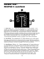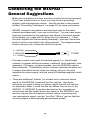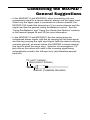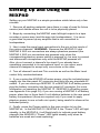
1
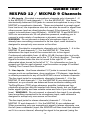
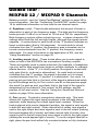
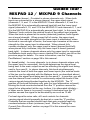
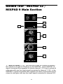
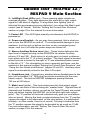
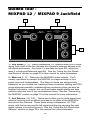
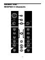
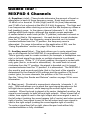
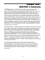
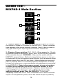
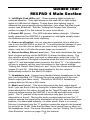
MIXPAD
M
DII
D
PA
O A
AU
O
U
X
CO
ER
O A
O
AU
U
D
DII
D
O AU
IO AU
D
PA
X
I
I
D
M
SAMSON
®
CT M
I
Produced by On The Right Wavelength for Samson Technologies Corp.
Copyright 1996, 1997, Samson Technologies Corp.
Printed February, 1997
Samson Technologies Corp.
575 Underhill Blvd.
P.O. Box 9031
Syosset, NY 11791-9031
Phone: 1-800-3-SAMSON (1-800-372-6766)
Fax: 516-364-3888
www.samsontech.com
Table of Contents
Introduction 1
MIXPAD Features 2
Guided Tours 4
MIXPAD 12/9 Channels 4
MIXPAD 12/9 Main Section 8
MIXPAD 12/9 Jackfield 10
Connecting the MIXPAD 4 Carrying Strap 11
MIXPAD 4 Channels 12
MIXPAD 4 Main Section 16
MIXPAD 4 Jackfield 18
Connecting the MIXPAD 19
Setting Up and Using the MIXPAD 22
Setting the Correct Gain Structure 23
Grounding Techniques 26
Using Pan/Balance 28
Using Equalization 30
Using Aux Sends and Returns 32
Appendix A: Operating the
MIXPAD 12/9 off Battery Power 34
MIXPAD 12/9 Specifications 36
MIXPAD 4 Specifications 37
Introduction
Congratulations on your purchase of the Samson MIXPAD! One of the
smallest mixers ever made, the MIXPAD provides excellent sound
quality and a wealth of features normally found only in full-size units.
Although it has been designed for easy operation, we suggest you take
some time to go through these pages so you can fully understand how
we’ve implemented a number of unique functions.
This manual covers three models: the MIXPAD 12, MIXPAD 9, and
MIXPAD 4. The first two of these are identical apart from the fact that
the MIXPAD 12 provides six monophonic and three stereo input
channels (for a total of twelve channels), while the MIXPAD 9 provides
three monophonic and three stereo input channels (for a total of nine
channels). The MIXPAD 4 provides two monophonic input channels
and one stereo input channel (for a total of four channels) and offers a
slightly different feature set (such as three-band equalization and
independent channel phantom power switches). Because of their
unusually small size and portability, all three models are well-suited for
specialized applications such as videography, remote site recording,
ENG (Electronic News Gathering), or audio coverage of fast-paced
outdoor events such as sports shows.
In these pages, we’ll provide you with an overview of the unit’s features,
followed by a guided tour of the MIXPAD channels, main section and
jackfield. Then we’ll describe how to set up your MIXPAD, including
instructions on how to set the optimum gain structure. Next, we’ll cover
a number of specific MIXPAD functions (such as panning, equalization,
and auxiliary sends and returns) in detail. Finally, we’ll wrap things up
with full specifications. You’ll also find a warranty card enclosed—
please don’t forget to fill it out and mail it so that you can receive online
technical support and so we can send you updated information about
these and other Samson products in the future.
SPECIAL NOTE: Should your MIXPAD ever require servicing, a Return
Authorization (RA) number is necessary. Without this number, the unit
will not be accepted. Please call Samson at 1-800-372-6766 for a
Return Authorization number prior to shipping your unit. Please retain
the original packing materials and, if possible, return the unit in its
original carton and packing materials.
1
MIXPAD Features
The compact design of the MIXPAD belies an extraordinary versatility.
Add excellent sound quality to the equation, and you’ve got a product
which is equally useful as a live performance mixer and for field
recording applications. Here are some of the MIXPAD’s main features:
• In the MIXPAD 12, a total of twelve input channels (including three
stereo channels); in the MIXPAD 9, a total of nine input channels
(including three stereo channels); in the MIXPAD 4, a total of four
input channels (including one stereo channel). Monophonic
channels provide electronically balanced inputs that can be used for
microphone or line-level input, while stereo channels are ideal for
line-level sources such as outboard signal processors; CD players;
tape or cassette recorders; stereo drum machines; and keyboards
and MIDI tone modules.
• An electronically balanced main stereo output for connection to a
power amplifier or tape recorder.
• A dedicated Tape/CD input for playback of prerecorded material.
• In the MIXPAD 12 and MIXPAD 9, two auxiliary sends and two
stereo auxiliary returns (which can be used as four monophonic
returns). Aux send 1 is pre-fader (but post-equalizer), making it ideal
for use as a headphone or monitor cue mix, while Aux send 2 is
post-fader and post-equalizer.
• In the MIXPAD 4, one auxiliary send and one stereo auxiliary return
(which can be used as two monophonic returns), with the aux send
post-fader and post-equalizer.
• In the MIXPAD 12 and MIXPAD 9, independent 2-band equalization
for each channel, with 15 dB of cut or boost for low (100 Hz) and
high (10 kHz) frequencies.
• In the MIXPAD 4, independent 3-band equalization for each channel,
with 15 dB of cut or boost for low (80 Hz) and high (12 kHz)
frequencies, and 12 dB of cut or boost for the mid (2.5 kHz)
frequency.
2
MIXPAD Features
• Constant level pan controls for placing each monophonic channel in
the left-right stereo spectrum, as well as balance controls that allow
you to blend the relative levels of stereo inputs.
• Mic input trims that are continuously adjustable from +4 to -50 dB,
making it possible to use the MIXPAD with a wide variety of
microphones.
• The MIXPAD 12 and MIXPAD 9 provide 36 volts of phantom power
to all mic inputs, while the MIXPAD 4 provides 18 volts of phantom
power (with independent switches for each of its two mic input
channels), making it possible to use most condenser and dynamic
mics, as well as active DI (Direct Injection) boxes.
• Peak LEDs for the left and right main outputs, showing you when
signal is overloading or near overloading.
• Center detents for all pan, balance, and EQ controls, making it
easy to access them in low-light situations such as live performance.
• Convenient front-panel Power switch, Power LED and dedicated
headphone jack.
• The MIXPAD 4 runs on either AC or battery power (requiring just two
standard 9 volt batteries—three if you need phantom power), with
optional battery power available for the MIXPAD 12 and MIXPAD 9
(see Appendix A on page 34), enabling the unit to be used for
ENG (Electronic News Gathering), field broadcast and recording
purposes. In the MIXPAD 4, the front-panel Power LED also
indicates battery strength.
• The MIXPAD 4 includes a handy carrying strap for easy portability.
• Last but certainly not least, affordability. The Samson MIXPAD
has been designed from the ground up to provide versatility and
excellent sound quality at a cost-conscious price.
3
Guided Tour MIXPAD 12 /MIXPAD 9 Channels
1
MIC
-10
2
0
TRIM
+4
L
-50
MONO
3
R
LINE
O
O
-15
+15
-15
HIGH
-15
+15
HIGH
4
O
O
+15
-15
LOW
+15
LOW
O
O
+10
PRE
+10
PRE
5
AUX1
AUX1
O
O
+10
+10
AUX 2
AUX 2
6
L
7
R
PAN
O
L
R
BALANCE
O
8
+10
+10
LEVEL
LEVEL
Mono Channel
Stereo Channel
4
Guided Tour MIXPAD 12 / MIXPAD 9 Channels
1: Mic inputs - Provided in monophonic channels only (channels 1 - 6
in the MIXPAD 12 and channels 1 - 3 in the MIXPAD 9). Use these
electronically balanced XLR jacks to connect microphones to any of the
MIXPAD’s monophonic channels. These are intended to accept signal
from low-level, low-impedance mics but can also be used for signal from
other sources (such as direct injection boxes) if the channel’s Trim
control is turned down (see #2 below). All MIXPAD 12 and MIXPAD 9
XLR mic connectors are 36 volt phantom powered, enabling you to
connect a wide variety of condenser or dynamic microphones.
WARNING: Do not connect a channel’s microphone input if you
already have something connected to its line input; each channel is
designed to accept only one source or the other.
2: Trim - Provided in monophonic channels only (channels 1 - 6 in the
MIXPAD 12 and channels 1 - 3 in the MIXPAD 9). This knob
determines the input level of the connected mic or line signal.
Continuously adjustable from +4 dB to -50 dB, the input trim is at unity
gain (no boost or cut) when set to the “0” (9 o’clock) position. The input
signal is boosted when the trim is turned to the right of “0” and
attenuated when turned to the left of “0.” For information on how to
properly set this for each channel, see the section on page 23 entitled
“Setting The Correct Gain Structure.”
3: Line inputs - Use these standard 1/4" jacks to connect line-level
sources such as synthesizers, drum machines, CD players, tape decks,
or effects processors to any of the MIXPAD’s mono or stereo channels.
The line input jacks for monophonic channels (channels 1 - 6 in the
MIXPAD 12 and channels 1 - 3 in the MIXPAD 9) are electronically
balanced, so you should use balanced three-conductor cabling and
Tip/Ring/Sleeve (TRS) plugs wherever possible (unbalanced twoconductor plugs can also be inserted into these inputs, but you’ll get
better signal quality and less outside noise and hum if you use balanced
lines). WARNING: Do not connect a channel’s line input if you already
have something connected to its microphone input; each channel is
designed to accept only one source or the other.
The line input jacks for stereo channels (channels 7 - 12 in the
MIXPAD 12 and channels 4 - 9 in the MIXPAD 9) are unbalanced.
When connecting only one monophonic signal to stereo channels, use
the left (even-numbered) input; the MIXPAD will then treat that channel
as if it is a mono channel, allowing the signal to be panned (using the
5
Guided Tour MIXPAD 12 / MIXPAD 9 Channels
Balance control)—see the “Using Pan/Balance” section on page 28 for
more information. See the “Connecting The MIXPAD” section on page
19 for additional information on how best to use channel inputs.
4: Equalizer (violet) - These knobs determine the amount of boost or
attenuation in each of two frequency areas. The high and low frequency
knobs provide 15 dB of cut or boost at 10 kHz and 100 Hz, respectively.
Both frequency controls utilize a shelving curve. In stereo channels, EQ
settings affect both the left and right inputs, although the signals remain
separate. A center detent in each knob (at the “0” position) indicates no
boost or attenuation (that is, flat response). As each knob is turned
clockwise from the “0” position, the frequency area is boosted; as it is
turned counterclockwise from the “0” position, the frequency area is
attenuated. For more information on the application of EQ, see the
“Using Equalization” section on page 30.
5: Auxiliary sends (blue) - These knobs allow you to route signal to
either or both of the MIXPAD’s two monophonic Auxiliary outputs.
These are typically used to create submixes (for example, a headphone
cue mix) and to feed signal from single or multiple channels to outboard
effects devices. At the “0” (2 o’clock) position, the signal is routed with
unity gain (that is, no boost or attenuation). As each knob is turned
clockwise from the “0” position, the signal is boosted; as it is turned
counterclockwise from the “0” position, it is attenuated. Aux send 1 is
post-eq but pre-fade; that is, the level of the signal is determined solely
by its EQ settings and by its Trim control; see #2 on the previous page.
Aux send 2 is post-eq and post-fade; that is, the level of the signal is
determined by the channel’s Trim control, its EQ settings, and the
position of its Level control. See the “Using Aux Sends and Returns”
section on page 32 for more information.
6: Pan (green) - Provided in monophonic channels only. This knob
allows you to place the input signal anywhere in the left-right stereo
spectrum, while keeping the overall signal level constant. When the
knob is placed at its center (detented) position, the signal is sent equally
to both left and right outputs. When moved left of center, less signal is
sent to the right output and more signal is sent to the left output (making
the sound appear left of center) and when moved right of center, less
signal is sent to the left output and more signal is sent to the right output
(making the sound appear right of center). To route a signal hard left or
right, place the pan knob either fully counterclockwise or fully clockwise.
6
Guided Tour MIXPAD 12 / MIXPAD 9 Channels
7: Balance (brown) - Provided in stereo channels only. When both
inputs are connected to a stereo channel, the upper input signal
(channels 7, 9, and 11 in the MIXPAD 12 and channels 4, 6, and 8 in
the MIXPAD 9) is automatically panned hard left and the lower input
signal (channels 8, 10, and 12 in the MIXPAD 12 and channels 5, 7, and
9 in the MIXPAD 9) is automatically panned hard right. In this case, the
“Balance” knob controls the relative levels of the paired input signals.
When the knob is placed at its center (detented) position, both signals
are at equal strength. When moved left of center, the upper input
remains at the same strength but the lower input is attenuated; when
the knob is moved right of center, the lower input remains at the same
strength but the upper input is attenuated. When placed fully
counter-clockwise, only the upper input is heard (panned hard left);
when placed fully clockwise, only the lower input is heard (panned
hard right). In stereo channels where only the upper input is connected,
the Balance knob works like a mono channel Pan control; see #6 on the
previous page for details. For more information, see the “Using
Pan/Balance” section on page 28 in this manual.
8: Level (white) - In mono channels (or in stereo channels where only
the upper input is connected), this knob determines the signal level
being sent to the main output as well as affecting the signal level being
sent to Aux send 2. In stereo channels, this knob simultaneously
controls the level of both the upper and lower inputs (the relative levels
of the two can be adjusted with the Balance knob, as described above)
as well as the signal level being sent to Aux send 2. In practice, you will
use the channel Level controls to continuously adjust the levels of the
various signals being blended together by the MIXPAD. The “0”
position of the knob indicates unity gain (no level attenuation or boost).
Moving the knob counterclockwise from the “0” position causes the
signal to be attenuated (at the very bottom, it is attenuated infinitely—
in other words, there is no sound); moving it clockwise from the “0”
position causes the signal to be boosted by as much as 10 dB.
For best signal-to-noise ratio, all Level controls for channels
carrying signal should generally be kept at or near the “0” position.
Channels that are unused should have their gain controls kept fully
counterclockwise at their (minimum) level. See the “Setting the
Correct Gain Structure” section on page 23 in this manual for more
information.
7
Guided Tour - MIXPAD 12 /
MIXPAD 9 Main Section
TAPE/CD
1
LEFT
RIGHT
LEFT
RIGHT
2
4
3
POWER
O
AUX
+10
RET.1/2
5
O
AUX
+10
RET. 3/4
6
O
7
+10
MAIN LEVEL
1: Tape/CD inputs (L, R) - Use this set of dual RCA jacks to connect
the outputs of a tape or CD player to the MIXPAD. In the MIXPAD 12,
signal connected here appears at stereo channel 11/12 and is mixed at
unity gain with any line input signal connected to channel 11/12. In the
MIXPAD 9, signal connected here appears at stereo channel 8/9 and is
mixed at unity gain with any line input signal connected to channel 8/9.
8
Guided Tour - MIXPAD 12 /
MIXPAD 9 Main Section
2: Left/Right Peak LEDs (red) - These warning lights indicate an
overload situation. They light whenever the main left or right output
signal is 5 dB short of clipping. To stop them from lighting (and to
eliminate the accompanying sonic distortion), turn down the Main Level
control (see #7 below). See the “Setting the Correct Gain Structure”
section on page 23 in this manual for more information.
3: Power LED - This LED lights steadily red whenever the MIXPAD is
powered on.
4: Power on-off switch - As you may have guessed, this is what you
use to turn the MIXPAD on and off. To avoid potential damage to your
speakers, turn the unit on before you turn on any connected power
amps—and turn it off after the power amps are turned off.
5: Stereo Auxiliary Return Level (tan) - These knobs determine the
input level of signal arriving via the MIXPAD’s two stereo Auxiliary
returns (1/2 and 3/4). Each return is at unity gain (no boost or attenuation) when set to the “0” (2 o’clock) position. The input signal is boosted
when the knob is turned to the right of “0” and attenuated when turned
to the left of “0.” For information on how to properly set these, see the
sections in this manual entitled “Setting the Correct Gain Structure” and
“Using the Aux Sends and Returns” (pages 23 and 32). Auxiliary return
signal is automatically routed to the Main L/R output.
6: Headphone jack - Connect any standard stereo headphones to this
jack (via a standard 1/4" TRS plug) for private monitoring of the main
stereo output. The built-in MIXPAD headphone preamp delivers
100 mw at 600 ohms.
7: Main Level (white) - This knob determines the final output signal
level—you can think of this as being the “master fader.” Signals from all
channels and Auxiliary returns, as well as the Tape/CD input are routed
here just before leaving the MIXPAD via its left and right main output
jacks. The “0” position of the knob indicates unity gain (no level attenuation or boost). Moving the knob counterclockwise from the “0” position
causes the signal to be attenuated (at the very bottom, it is attenuated
infinitely—in other words, there is no sound). Moving it clockwise from
the “0” position causes the signal to be boosted by as much as 10 dB.
For more information, see the “Setting The Correct Gain Structure”
section on page 23 in this manual.
9
Guided Tour MIXPAD 12 / MIXPAD 9 Jackfield
2
1
AUX
SEND 1
AUX
SEND 2
LEFT
OUTPUT
BALANCED
+4dBu
RIGHT
AUX
RETURN
1/2
AUX
RETURN
3/4
3
1: Aux Sends (1, 2) - These unbalanced 1/4" outputs allow you to route
signal from each of the two discrete Aux Sends to external devices such
as effects processors. Aux send 1 is pre-fade but post-EQ, while Aux
send 2 is both post-fade and post-EQ. See the “Using the Aux Sends
and Returns” section on page 32 in this manual for more information.
2: Main out (L, R) - These are the MIXPAD’s main outputs. You’ll
usually use these to connect the MIXPAD to a tape recorder or to a
power amp and loudspeakers. The Main out jacks are electronically
balanced, so you should use balanced three-conductor cabling and TRS
plugs wherever possible (unbalanced two-conductor plugs can also be
inserted into these outputs, but you’ll get better signal quality and less
outside noise and hum if you use balanced lines). See the “Connecting
the MIXPAD” section on page 19 in this manual for more information.
3: Aux Returns (1/2, 3/4) - These inputs allow you to route signal from
external devices such as effects processors to either of the MIXPAD's
two stereo Aux Returns. These jacks accept unbalanced 1/4" TRS
plugs, with the tip carrying the left signal and the ring carrying the right
signal (sleeve is common ground). See the “Using the Aux Sends and
Returns” section on page 32 in this manual for more information.
10
Connecting the MIXPAD 4
Carrying Strap
MIXPAD4
XLR/LINE INPUT
2/TIP
+
3/RING
-
1
5
1/SLEEVE GND
2
AUX SEND/RETURN
TIP
4
AVIS;
RISQUE DE CHOC ELECTRIQUE
NE PAS OUVRIR
DO NOT EXPOSE THIS EQUIPMENT
TO RAIN OR MOISTURE
3
+
SLEEVE GND.
D.C. INPUT
DC INPUT
PIN 1 +15V
PIN 4 +32V
PIN 2 -15V
PIN 5 GND
S/N
PIN 3 GND
M IXPAD 4
The MIXPAD 4 is supplied with a handy carrying strap for easy
portability. As shown in the illustration above, attach the strap to the
MIXPAD 4 by placing the buckles in the connector slots and pressing
them in firmly until they snap in place. Remove the carrying strap by
gently squeezing together the outside buckle clips in order to extract
them from the connector slots.
11
Guided Tour MIXPAD 4 Channels
1
MIC
-20
-10
2
0
TRIM
-50
-6
4R
3L
3
LINE
LINE
O
-15
O
+15
HIGH
-15
+15
HIGH
O
O
4
-12
+12
MID
-12
-15
+12
MID
O
O
+15
LOW
-15
+15
LOW
O
O
5
∞
∞
+10
AUX
+10
AUX
6
L
R
PAN
L
R
BALANCE
7
O
O
8
∞
∞
+10
LEVEL
+10
LEVEL
12
Guided Tour MIXPAD 4 Channels
1: Mic inputs - Provided in monophonic channels only (channels 1 and
2). Use these electronically balanced XLR jacks to connect microphones
to either of the MIXPAD 4’s two monophonic channels. These are
intended to accept signal from low-level, low-impedance mics but can
also be used for signal from other sources (such as direct injection
boxes) if the channel’s Trim control is turned down (see #2 below).
When the channel’s Phantom Power switch is pressed in (see #2 on
page 16), 18 volts of phantom power is delivered to pins 2 and 3 of that
channel’s XLR mic input, enabling you to connect most condenser
microphones. WARNING: Do not connect a channel’s microphone
input if you already have something connected to its line input; each
channel is designed to accept only one source or the other.
2: Trim - Provided in monophonic channels only (channels 1 and 2).
This knob determines the input level of the connected mic or line signal.
Continuously adjustable from -6 dB to -50 dB, the input trim is at unity
gain (no boost or cut) when set to the “0” (9 o’clock) position. The input
signal is boosted when the trim is turned to the right of “0” and
attenuated when turned to the left of “0.” For information on how to
properly set this for each channel, see the section on page 23 in this
manual entitled “Setting The Correct Gain Structure.”
3: Line inputs - Use these 1/4" jacks to connect line-level sources such
as synthesizers, drum machines, CD players, tape decks, or effects
processors to any of the MIXPAD’s mono or stereo channels. The line
input jacks for monophonic channels (channels 1 - 2) are electronically
balanced, so you should use balanced three-conductor cabling and
Tip/Ring/Sleeve (TRS) plugs wherever possible (unbalanced twoconductor plugs can also be inserted into these inputs, but you’ll get
better signal quality and less outside noise and hum if you use balanced
lines). WARNING: Do not connect a channel’s line input if you already
have something connected to its microphone input; each channel is
designed to accept only one source or the other.
The line input jack for the stereo channel (channels 3 - 4) accepts a
single unbalanced 1/4" TRS plug, with the tip carrying the left signal and
the ring carrying the right signal (sleeve is common ground). See the
“Connecting The MIXPAD” section on page 19 in this manual for
additional information on how best to use channel inputs.
13
Guided Tour MIXPAD 4 Channels
4: Equalizer (violet) - These knobs determine the amount of boost or
attenuation in each of three frequency areas. Each knob provides
15 dB of cut or boost at 12 kHz (High) and 80 Hz (Low) frequencies,
and 12 dB of cut or boost at the Mid (2.5 kHz) frequency. The High and
Low frequencies utilize shelving curves and the Mid frequency utilizes a
bell (peaking) curve. In the stereo channel (channels 3 - 4), the EQ
settings affect both inputs, although the signals remain separate.
A center detent in each knob (at the “0” position) indicates no boost or
attenuation (that is, flat response). As each knob is turned clockwise
from the “0” position, the frequency area is boosted; as it is turned
counterclockwise from the “0” position, the frequency area is
attenuated. For more information on the application of EQ, see the
“Using Equalization” section on page 30 in this manual.
5: Auxiliary send (blue) - This knob allows you to route signal from
any or all channels to the MIXPAD 4’s monophonic Auxiliary output.
This is typically used to create a submix (for example, a headphone cue
mix) or to feed signal from single or multiple channels to outboard
effects devices. At the “0” (2 o’clock) position, the signal is routed with
unity gain (that is, no boost or attenuation). As each knob is turned
clockwise from the “0” position, the signal is boosted; as it is turned
counterclockwise from the “0” position, it is attenuated. The MIXPAD 4
Aux send is post-eq and post-fade; that is, the level of the signal is
determined by the channel’s EQ settings and the position of its Level
control (plus, in mono channels, the position of its Trim control).
See the “Using Aux Sends and Returns” section on page 32 for more
information.
6: Pan (green) - Provided in monophonic channels (channels 1 - 2)
only. This knob allows you to place the input signal anywhere in the
left-right stereo spectrum, while keeping the overall signal level
constant. When the knob is placed at its center (detented) position, the
signal is sent equally to both left and right outputs. When moved left of
center, less signal is sent to the right output and more signal is sent to
the left output (making the sound appear left of center) and when moved
right of center, less signal is sent to the left output and more signal is
sent to the right output (making the sound appear right of center).
To route a signal hard left or right, place the pan knob either fully
counterclockwise or fully clockwise.
14
Guided Tour MIXPAD 4 Channels
7: Balance (brown) - Provided in the stereo channel (channels 3 - 4)
only. When both inputs are connected to the stereo channel, the
channel 3 input signal is automatically panned hard left and the channel
4 input signal is automatically panned hard right. In this case, the
“Balance” knob controls the relative levels of the paired input signals.
When the knob is placed at its center (detented) position, both signals
are at equal strength. When moved left of center, the channel 3 input
remains at the same strength but the channel 4 input is attenuated; when
the knob is moved right of center, the channel 4 input remains at the
same strength but the channel 3 input is attenuated. When placed fully
counter-clockwise, only the channel 3 input is heard (panned hard left);
when placed fully clockwise, only the channel 4 input is heard (panned
hard right). For more information, see the “Using Pan/Balance” section
on page 28 in this manual.
8: Level (white) - This knob determines the signal level being sent to the
main output. When both channels are connected in the stereo channel ,
this knob simultaneously controls the level of both inputs (the relative
levels of the two can be adjusted with the Balance knob, as described
above). In practice, you will use the channel Level controls to
continuously adjust the levels of the various signals being blended
together by the MIXPAD 4. The “0” position of the knob indicates unity
gain (no level attenuation or boost). Moving the knob counterclockwise
from the “0” position causes the signal to be attenuated (at the very
bottom, it is attenuated infinitely—in other words, there is no sound);
moving it clockwise from the “0” position causes the signal to be boosted
by as much as 10 dB.
For best signal-to-noise ratio, all Level controls for channels
carrying signal should generally be kept at or near the “0” position.
Channels that are unused should have their gain controls kept fully
counterclockwise at their (minimum) level. See the “Setting the
Correct Gain Structure” section on page 23 in this manual for more
information.
15
Guided Tour MIXPAD 4 Main Section
TAPE/CD INPUT
1
3L
4R
PHANTOM POWER
2
CH1
L
CH2
3
PEAK
R
5
4
POWER
O
6
∞
+10
AUX RET 1/2
7
O
8
∞
+10
MAIN LEVEL
1: Tape/CD inputs (L, R) - Use this set of dual RCA jacks to connect
the outputs of a tape or CD player to the MIXPAD 4. Signal connected
here appears at the stereo channel (channels 3 and 4) and is mixed at
unity gain with any line input signal connected to channel 3/4.
2: Phantom Power switches (Ch 1, Ch 2) - When pressed in, 18 volts
of phantom power is delivered to pins 2 and 3 of the XLR mic connector
of the selected channel. WARNING: Only use this switch with the
MIXPAD 4 powered down. Before turning phantom power on, be sure
to disconnect all non-microphone signal sources (such as passive direct
injection boxes) from the XLR mic jacks. Although phantom power will
have no adverse affect on connected dynamic microphones, it should
be used only when one or more condenser microphones are connected
to the MIXPAD 4. Refer to the owners manual of your microphone
or active direct injection (DI) box to determine whether or not it
requires 18 volts of phantom power—Samson cannot assume
responsibility if you damage a mic or DI box by incorrectly
applying phantom power from the MIXPAD 4. If you’re not
completely certain that one or more connected mics or active DI boxes
require 18 volts phantom power, leave this switch off (its out position).
16
Guided Tour MIXPAD 4 Main Section
3: Left/Right Peak LEDs (red) - These warning lights indicate an
overload situation. They light whenever the main left or right output
signal is 5 dB short of clipping. To stop them from lighting (and to
eliminate the accompanying sonic distortion), turn down the Main Level
control (see #8 below). See the “Setting the Correct Gain Structure”
section on page 23 in this manual for more information.
4: Power LED (green) - This LED indicates battery strength. It flashes
briefly whenever the MIXPAD 4 is powered on and lights steadily when
the batteries are low and need replacing.
5: Power on-off switch - As you may have guessed, this is what you
use to turn the MIXPAD 4 on and off. To avoid potential damage to your
speakers, turn the unit on before you turn on any connected power
amps—and turn it off after the power amps are turned off.
6: Stereo Auxiliary Return Level (tan) - This knob determines the input
level of signal arriving via the MIXPAD 4’s stereo Auxiliary return. The
Aux return is at unity gain (no boost or attenuation) when set to the “0”
(2 o’clock) position; the signal is boosted when the knob is turned to the
right of “0” and attenuated when turned to the left of “0.” For information
on how to properly set this, see the sections in this manual entitled
“Setting the Correct Gain Structure” and “Using Aux Sends and Returns”
(pages 23 and 32). Note that signal applied to the Aux return is
automatically routed to the Main L/R output.
7: Headphone jack - Connect any standard stereo headphones to this
jack (via a standard 1/4" TRS plug) for private monitoring of the main
stereo output (pre-Main Level). The built-in MIXPAD 4 headphone
preamp delivers 38 mw at 600 ohms.
8: Main Level (white) - This knob determines the final output signal
level—you can think of this as being the “master fader.” Signals from all
channels and the Aux return, as well as the Tape/CD input are routed
here just before leaving the MIXPAD 4 via its left and right main output
jacks. The “0” position of the knob indicates unity gain (no level
attenuation or boost). Moving the knob counterclockwise from the “0”
position causes the signal to be attenuated (at the fully counterclockwise
position, it is attenuated infinitely—in other words, there is no sound).
Moving it clockwise from the “0” position causes the signal to be boosted
by as much as 10 dB. Note that the Main Level control has no effect on
the headphone level. For more information, see the “Setting The Correct
Gain Structure” section on page 23 of this manual.
17
Guided Tour MIXPAD 4 Jackfield
1
LEFT
MAIN OUTPUT
RIGHT
BALANCED +4dBu
AUX SEND
AUX RET 1/MONO
3
2
AUX RET 2
1: Main out (L, R) - These are the MIXPAD 4’s main outputs. You’ll
usually use these to connect the MIXPAD 4 to a tape recorder or to a
power amp and loudspeakers. The Main out jacks are electronically
balanced, so you should use balanced three-conductor cabling and
TRS plugs wherever possible (unbalanced two-conductor plugs can also
be inserted into these outputs, but you’ll get better signal quality and
less outside noise and hum if you use balanced lines). See the
“Connecting the MIXPAD” section on page 19 for more information.
2: Aux Send - This unbalanced 1/4" output allows you to route signal
from any or all channels to external devices such as effects processors.
The MIXPAD 4 Aux send is post-fade and post-EQ. See the “Using Aux
Sends and Returns” section on page 32 for more information.
3: Aux Return (1/Mono / 2) - These unbalanced 1/4" inputs allow you
to route signal from external devices such as effects processors to the
MIXPAD 4’s stereo Aux Return. When connecting only a single mono
signal to the Aux Return, use the “ Aux Ret. 1/Mono” input; the signal
will then be automatically panned dead center. When connecting stereo
signals, use both jacks; the signal connected to the “Aux Ret. 1/Mono”
jack will be automatically panned hard left and the signal connected to
the “Aux Ret 2” jack will be automatically panned hard right. See
“Using Aux Sends and Returns” on page 32 for more information.
18
Connecting the MIXPAD General Suggestions
The actual connections you’ll make to and from the MIXPAD will vary
according to the environment you use it in and the particular equipment
you have, but here are a few basic rules concerning MIXPAD
connections that will apply in most situations:
• In general, it’s best to make all connections with the MIXPAD and
any connected power amplifiers turned off. If you must make
connections with the power on, make sure that the Main Level
control is completely down (turn the knob fully counterclockwise).
Whenever powering down, turn the Main Level control completely
down and turn off the main power amps first. Wait a few seconds
for their power supplies to discharge and then turn off all connected
equipment, turning the MIXPAD off last.
• Try to use balanced connectors and cabling wherever possible.
These kind of connections do a better job of rejecting extraneous
noise and hum and generally provide a cleaner signal. Although
the MIXPAD will accept unbalanced connectors throughout, it
specifically provides electronically balanced inputs for all mono line
inputs (channels 1 - 6 in the MIXPAD 12; channels 1 - 3 in the
MIXPAD 9; and channels 1 - 2 in the MIXPAD 4) and for its main
outputs. The wiring diagram below shows how 1/4" TRS
(Tip/Ring/Sleeve) connectors should be wired for use with these
inputs and outputs:
SLEEVE
TIP +
GROUND
RING -
TIP
RING
Unbalanced cables use standard 1/4" phone connectors, wired as
follows:
+ SIGNAL
+ SIGNAL
GROUND
GROUND
19
Connecting the MIXPAD General Suggestions
• Make one connection at a time and then monitor the incoming signal.
If you hear a distinct hum or buzz, you may have a grounding
problem with that particular device. See the section in this manual
entitled “Grounding Techniques” (on page 26) for more information.
• NEVER connect a microphone and line level input to the same
channel simultaneously—use one or the other. You can have some
channels connected to microphones and others to line level signals
(for example, you might want to plug mics into channels 1 - 2 and
line level signals into the remaining channels)—just don’t have both
kinds of inputs connected to the same channel. The diagram below
shows how your mic connectors should be wired:
3 - SIGNAL
1 GROUND
2 + SIGNAL
T TO MIC
• For easy control over a pair of matched signals (i.e. the left-right
outputs of a stereo effects processor, keyboard, drum machine, tone
generator, CD player, or tape recorder), use the MIXPAD’s stereo
input channels. The Balance control in these channels will allow you
to adjust the relative levels of the two inputs, and you can also
equalize the stereo signal, with the same EQ settings applied to both
inputs.
• There are additional “hidden” (or at least not so obvious) stereo
inputs to the MIXPAD; these are the Aux returns. Use these
whenever you want to bring in a stereo signal that will not need to
be equalized. Bear in mind that the two stereo Aux returns in the
MIXPAD 12 / MIXPAD 9 can also be used as four monophonic
returns and that the single stereo Aux return in the MIXPAD 4 can
also be used as two monophonic returns (when connecting only
one monophonic signal, use the “Aux Ret. 1/Mono” jack so that the
returning signal is automatically panned dead center).
20
Connecting the MIXPAD General Suggestions
• In the MIXPAD 12 and MIXPAD 9, when connecting only one
monophonic signal to a stereo channel, always use the upper input.
When only the upper input is connected in a stereo channel, the
MIXPAD 12/9 treats that channel as if it is a mono channel and the
signal can then be panned (using the Balance control). See the
“Using Pan/Balance” and “Using Aux Sends And Returns” sections
in this manual (pages 28 and 32) for more information.
• In the MIXPAD 12 and MIXPAD 9, the Aux return jacks are
unbalanced stereo inputs, with the tip carrying the left input signal
and the ring carrying the right input signal (with the sleeve carrying
common ground), as shown below (the MIXPAD 4 stereo channel
line input is wired the same way). Insertion of a monophonic 1/4"
jack into an Aux return will result in the incoming signal being
automatically routed to the left input only (and therefore panned
hard left).
TIP (LEFT SIGNAL)
RING (RIGHT SIGNAL)
SLEEVE (COMMON GROUND)
21
Setting Up and Using the
MIXPAD
Setting up your MIXPAD is a simple procedure which takes only a few
minutes:
1. Remove all packing materials (save them in case of need for future
service) and decide where the unit is to be physically placed.
2. Begin by connecting the MIXPAD main left/right outputs to a tape
recorder or power amp (and the amp into loudspeakers). It is never
a good idea to power up any amplifier that is not connected to
loudspeakers.
3. Next, make the signal input connections to the mic or line inputs of
the various channels. WARNING: Because the MIXPAD 12 and
MIXPAD 9 XLR mic connectors are always phantom powered (the
MIXPAD 4 XLR mic connectors are powered only when the
corresponding phantom power switch is pressed in), be sure to connect
and disconnect microphones only with the MIXPAD powered off.
Also, do not connect a channel’s line input if you already have
something connected to its microphone input, or vice versa; each
channel is designed to accept only one source or the other.
4. Turn all channel Level and Trim controls as well as the Main Level
control fully counterclockwise.
5. If you running the MIXPAD off mains power, plug the included power
supply into the rear panel AC connector and then into any standard AC
socket. If you are running a MIXPAD 12 or MIXPAD 9 off battery power,
plug the battery connector into the rear panel AC connector (for more
information on operating the MIXPAD 12 / MIXPAD 9 off battery power,
see Appendix A on page 34); if you are running a MIXPAD 4 off battery
power, place two or three fresh 9 volt alkaline batteries in the rear panel
battery compartment (three are required only if you need to apply
phantom power to one or both mic inputs), being careful to observe the
indicated polarity.
6. Finally, press the Power switch in the main section to turn the
MIXPAD on. In the MIXPAD 12 / MIXPAD 9, the “Power” LED will light
steadily; in the MIXPAD 4, it will flash briefly to indicate good battery
strength (the MIXPAD 4 “Power” LED lights steadily only when its
batteries are weak and need replacing).
22
Setting the Correct Gain
Structure
You’re now ready to establish the correct gain structure—the key to
getting the best performance from the MIXPAD, or from any mixer, for
that matter. This is a simple procedure that ensures optimum input and
output levels so that no unnecessary noise (caused by too low a signal)
or overload distortion (caused by too high a signal) is created. Here’s a
step-by-step description of how to do so:
a. With all connections made (as described above) but with the power
amplifier and MIXPAD powered off, set the power amplifier volume to
minimum. On the MIXPAD, turn all channel Trim and Level controls fully
counterclockwise, and set the Main Level control to its “0” position.
b. If you are using a MIXPAD 4 and either or both connected
microphones require 18 volts phantom power, press in the corresponding
phantom power switch.
c. Set all channel equalizer and pan/balance knobs to their center
detented “0” positions.
d. Set all channel Aux send knobs and all Aux return level knobs fully
counterclockwise.
e. Turn on all devices connected to channel line inputs and Aux returns
and set their level controls to unity gain or, if there is no unity gain indicated on their output control, to maximum. If you’ve got effects processors connected to Aux returns, make sure they are sending completely
“wet” (processed) signal, with no “dry” (unprocessed) signal mixed in.
f. Press the MIXPAD Power switch in order to turn the unit on. Finally,
turn on the power amplifier and set it to a moderate listening level.
g. Play an instrument connected to one of the MIXPAD’s line inputs*
and, while doing so, slowly raise the corresponding channel Level control
to the 2 o’clock “0” position (for most line-level signals, the Trim control
should remain fully counterclockwise). Listen for signs of any distortion.
If you hear any, you may need to lower the output level of the instrument,
though this will rarely occur. Conversely, if the signal is too low,
something’s wrong: in all likelihood, the connecting audio cable is faulty.
* If you’re using an instrument such as electric guitar or bass, we
recommend that you connect it to the MIXPAD with a direct injection box
to ensure correct impedance.
23
Setting the Correct Gain
Structure
h. Once you’ve set the optimum level in step (g) above, continue
playing the instrument and slowly raise the power amplifier volume until
you reach the level you want to hear.
i. Repeat step (g) above for each instrument connected to the
MIXPAD channel line inputs.
j. The procedure for setting optimum microphone levels is virtually
identical; sing or speak into the mic at the level you expect to use in
performance while slowly raising the Level control for that channel to its
2 o’clock “0” position. Then carefully raise the Trim control for that
channel until the main Left/Right peak LEDs in the main section just
begin to light occasionally during the loudest signals. Again, listen
carefully for any signs of audible distortion or unusually weak signal
(indicating a likely fault in cabling).
k. If you have any outboard signal processors connected to the Aux
send and return jacks on the rear panel, follow this step. Because
outboard effects processors can sometimes be quite noisy, it’s
particularly important to maximize the amount of signal being sent to
them via the MIXPAD Aux sends. The idea is to drive these devices as
hot as possible (short of overloading them) and then to use the
corresponding Aux return level to carefully adjust the amount of
processed signal being blended with the dry signal. To set optimum
Aux send levels, use a channel that has already had its gain structure
adjusted in step (g) or (j) above. Turn the Aux send knob(s) for that
channel to the “0” (unity gain) position and then play the instrument
(or sing into the microphone) connected to that channel. Adjust the
input levels of connected outboard effects processors so that their meter
shows incoming signal normally in the 0 vu range (with only occasional
higher excursions). Then it’s time to optimize the Aux return levels.
While continuing to play your instrument (or continuing to sing into the
microphone), slowly raise the Aux return level control(s) until you hear
the desired amount of processed signal added to the dry signal.
For more information, see the “Using the Aux Sends and Returns”
section on page 32 in this manual.
24
Setting the Correct Gain
Structure
l. The gain structure is now correctly set—you’ve optimized the level of
all signals coming into and out of the MIXPAD, and the end result will be
minimum noise and distortion and maximum clean sound. You’ll now
find that the majority of your mixes can be accomplished with most
channel Level controls at or near their 2 o’clock “0” (unity gain) position
and that the main Left/Right peak LEDs rarely if ever light (remember, if
they do light, it means that something is distorting!). If you need to make
adjustments to the overall level, alter the level control of your power
amplifier.
If you encounter difficulty with any aspect of setting up or using your
MIXPAD, you can call Samson Technical Support (1-800-372-6766)
between 9 AM and 5 PM EST.
25
Grounding Techniques
Hum and buzz are the biggest enemies you face when interconnecting
a large number of different pieces of equipment to a central audio mixer.
This is because each piece of equipment may operate at a marginally
different voltage (this difference is called potential) and, when two
devices at slightly different potential are physically connected with
audio cabling, the end result can be nasty, extraneous noise (mind you,
connecting two devices at very different potential can result in a major
electrical shock!).
However, there are several steps you can take to avoid grounding
problems. First, assuming you have an isolated electrical circuit that
can handle the electrical demands of your mixer and all connected
audio equipment (these needs will usually be modest), you should
always plug your mixer and all connected equipment into the same
circuit. If possible, nothing else but this equipment should be connected
to that circuit. If you can’t do this, at least avoid plugging your mixer and
audio equipment into the same circuit that is already powering things
like heavy machinery, air conditioners, heaters, refrigerators, washing
machines, neon signs or fluorescent light fixtures. One particular culprit
that will almost certainly create problems is the standard light dimmer
(the kind that uses silicon controlled rectifiers). Where low-level lighting
is desired, use incandescent fixtures with autotransformer-type dimmers
(sometimes called Variacs) instead—these cost considerably more than
the standard dimmer you’ll find at your local hardware store, but are well
worth the extra expense.
If you hear hum or buzz from a device that uses an external two-prong
AC/DC adapter (such as the MIXPAD), you can try reversing the plug in
the socket. If that doesn’t work, you may need to physically ground that
device’s chassis by connecting a wire (called a strap) from it to a
grounded piece of metal. Some pieces of equipment have a screw-type
ground post to which the strap can be connected; if not, you can attach
some kind of metallic binding post to the case itself. If you are using
rack-mounted audio devices and are experiencing hum or buzz, there’s
a simple test to determine the source of the problem: while keeping all
devices powered on and connected with audio cabling, physically
remove each device, one by one, from the rack. If the hum disappears
when a particular device is removed, you’ll know that device is probably
the culprit.
26
Grounding Techniques
We also recommend that you use balanced audio cabling and
connectors wherever possible. The MIXPAD provides electronically
balanced inputs for mono line channel inputs and for its main outputs.
The wiring diagram in the “Connecting The MIXPAD” section of this
manual (on page 19) shows how 1/4" TRS (Tip/Ring/Sleeve) connectors
should be wired for use with these inputs and outputs.
In addition, you can minimize possible interference by planning your
audio, electrical, and computer cable runs so that they are as far apart
from one another as possible and so they don’t run parallel to one
another. If they have to cross, try to ensure that they do so at a 90°
angle (that is, perpendicular to one another). In particular, try to keep
audio cabling away from external AC/DC adapters.
Another, less common problem you may encounter is that of oscillation
(a ringing tone), which, apart from being annoying, is potentially
dangerous to your speakers. This is generally caused either by poor
outside wiring or by returning a signal out of phase (most commonly from
an outboard signal processor). If audible oscillation occurs, try isolating
each input signal by turning down all other inputs. If one signal alone is
causing the problem, you should be able to eliminate the oscillation by
reversing that signal’s phase (many signal processors have a switch that
allows you to do this).
27
Using Pan/Balance
L
The final Main output of the
MIXPAD is stereo—that is, there
are two discrete output jacks,
labeled “left” and “right,” which
will normally be routed to a
stereo power amplifier and two
discrete speakers.* Because of
this, you will usually be working
with a stereo field that ranges from hard left to
hard right. The Pan control in monophonic
channels (and the Balance control in MIXPAD 12
and MIXPAD 9 stereo channels, when only the
upper input is connected) allows you to place
each individual sound at any point within this
left-right field, while keeping the overall level
constant.
OUTPUT
BALANCED
+4dBu
LEFT
R
PAN
RIGHT
You can use stereo panning creatively in a variety
of ways: For example, you might want to have
guitars coming from one speaker and keyboards
from another, or you might use panning to “spread” the signal from a
piano miked with two microphones—one over the bass notes (panned
left) and the other over the treble notes (panned right). By turning a Pan
knob while a signal is present, the sound appears to move in space (a
process known as dynamic panning)—this can be particularly effective
when applied to sound effects.
L
R
BALANCE
In live performance, you may want to resist the temptation to pan
anything completely hard left or right, since some members of the
audience not seated in the center of the venue may miss some signal
altogether. In these circumstances, you’re best to use modest panning,
with signals routed no further than the 9 o’clock and 3 o’clock positions.
* You can, of course, also use the MIXPAD monophonically—simply
route the same signal to both the left and right outputs.
28
Using Pan/Balance
In the MIXPAD 4 stereo channel (channels 3/4) and in MIXPAD 12 and
MIXPAD 9 stereo channels (channels 7/8, 9/10, and 11/12 in the
MIXPAD 12; channels 4/5, 6/7, and 8/9 in the MIXPAD 9) where both
inputs are connected, the upper input signal is automatically panned
hard left and the lower input signal is automatically panned hard right.
The Balance knob in these channels controls the relative levels of the
two input signals. When the knob is placed at its center (detented)
position, both the upper and lower inputs are at equal strength. When
moved left of center, the signal of the upper channel remains the same
but the signal of the lower channel is attenuated; when the knob is
moved right of center, the reverse occurs: the signal of the lower channel
remains the same but the signal of the upper channel is attenuated.
When placed fully counter-clockwise, only the upper channel is heard;
when placed fully clockwise, only the lower channel is heard.
29
Using Equalization
O
-15
+15
HIGH
O
-15
+15
LOW
MIXPAD 12/9 EQ
O
-15
HIGH
+15
O
-12
MID
+12
One of the most exciting aspects of using a mixer
such as the MIXPAD is the ability to shape a
sound, using a process called equalization. But
there are few areas of sound engineering more
misunderstood than equalization, and, just as
good EQ can really help a sound, bad EQ can
really hurt it, so read on...
Every naturally occurring sound consists of a
broad range of pitches, or frequencies, combined
together in a unique way. This blend is what
gives every sound its distinctive tonal color.
The EQ section in a mixer allows you to alter a
sound by boosting or attenuating specific
frequency areas. The MIXPAD 12 and MIXPAD 9
both provide independent two-band equalization
controls for each of their input channels, while the
MIXPAD 4 provides independent three-band
equalization controls for each input channel.
In all models, the EQ controls in stereo channels
affect both input signals identically.
O
Each EQ knob is labeled with the maximum
amount of cut or boost provided (± 15 dB in the
-15
+15
case of the High and Low frequencies, and, in
LOW
the MIXPAD 4, ±12 dB in the case of the Mid
MIXPAD 4 EQ
frequency). In the MIXPAD 12 and MIXPAD 9, the
High EQ knob affects frequencies above 10 kHz, while the Low EQ
knob affects frequencies below 100 Hz (with both using a shelving
curve). In the MIXPAD 4, the High EQ knob affects frequencies above
12 kHz, while the Low EQ knob affects frequencies below 80 Hz (with
both again using a shelving curve). The MIXPAD 4 also provides an
additional Mid EQ knob, affecting frequencies around 2.5 kHz (using a
bell, or peaking curve). We provided these particular frequency areas
because they have maximum impact on musical signals—that’s why
they are sometimes known as “sweet spots.” When an EQ knob is in its
center detented position (at “0”), it is having no effect. When it is moved
right of center, the particular frequency area is being boosted; when it is
moved left of center, the frequency area is being attenuated.
30
Using Equalization
In most instances, the best way to approach equalization is to think in
terms of which frequency areas you need to attenuate, as opposed to
which ones you need to boost (boosting a frequency area also has the
effect of boosting the overall signal; too much EQ boost can actually
cause overload—with the accompanying Left/Right Peak LED warning!).
Be aware of the phenomenon of masking, where loud sounds in one
frequency range obscure softer sounds in the same range; by cutting EQ
“notches” in a loud signal, you can actually make room for a softer one to
shine through. And try not to think of EQ as a miracle worker—no
amount of equalization can put a singer in tune or remove the distortion
from an overloaded input signal! The key is to get the signal right in the
first place, by using correct gain structure and mic placement.
Although the specific EQ you will apply to a signal is very much a matter
of personal taste, here are a few general suggestions: Boosting the low
frequency of instruments such as bass drums or bass guitar will add
warmth and make the sound “fatter”; conversely, you may want to
attenuate the low frequency component of instruments such as cymbals,
high-hats, and shakers so as to “thin” them out. Be careful not to boost
high frequencies too much or you risk adding hiss to the signal, though
just a touch can help add “shimmer” to an acoustic guitar, ride cymbal,
or high-hat. If you are using a MIXPAD 4, you’ll find the mid-range EQ
control to be particularly effective for vocals—attenuating it can give a
vocal performance more of an “FM-radio” feel and boosting it can help a
vocal cut through dense instrumentation. Finally, because the MIXPAD’s
High and Low EQ controls both utilize shelving curves, attenuated High
EQ settings can be used to reduce hiss (which is composed almost
exclusively of high frequencies) and attenuated Low EQ settings can be
used to reduce rumble (which is composed almost exclusively of low
frequencies).
31
Using Aux Sends and Returns
O
+10
PRE
AUX1
The purpose of Auxiliary sends are to allow you
to combine the signal from multiple channels
and send the resulting mix to external devices
such as effects processors. The MIXPAD 12
and MIXPAD 9 provide two such sends, while
the MIXPAD 4 provides one.
O
When a channel’s Aux send knob is at its
“0” position, the signal is routed with unity gain
AUX 2
(that is, no boost or attenuation). As it is turned
MIXPAD 12/9 Aux sends clockwise from the 0 position, the signal is
boosted; as it is turned counterclockwise from
the 0 position, it is attenuated. In the MIXPAD 12 and MIXPAD 9, Aux
send 1 is post-eq but pre-fader; that is, the level of the signal sent
through this knob is determined by the EQ settings and (in mono
channels) the position of the Trim control. It is, however, unaffected by
the channel Level setting; for this reason, it is optimum for applications
like headphone cueing or sending a feed to onstage monitors—both
situations where you want the performer’s mix to be independent of the
main mix. You can also use Aux 1 to route signal to a reverb processor
in order to create a distancing kind of effect where the “wet” reverb
signal remains constant even as the “dry” source signal fades away.
In contrast, Aux send 2 is post-eq and post-fader; that is, the level of the
signal is determined by EQ settings and the channel Level setting, as
well as (in mono channels) the position of the Trim control. This is the
condition of the single Aux send provided by the MIXPAD 4. Here, raising or lowering the Level of the channel will affect the send level as well.
+10
The MIXPAD 12 and MIXPAD 9 also provide
two stereo Aux returns (the MIXPAD 4
O
provides one stereo Aux return). These allow
you to return signal from outboard devices,
either in stereo pairs or monophonically (many
+10
AUX RET.1/2
popular effects processors provide a single
O
mono input but have two stereo outputs).
You can think of the MIXPAD’s stereo Auxiliary
returns as being somewhat similar to a stereo
+10
channel, except that a signal being brought into
AUX RET. 3/4
to a stereo channel can be equalized if
MIXPAD 12/9 Aux returns
necessary and optionally sent on to other
32
Using Aux Sends and Returns
outboard devices (via Aux sends). In
AUX
RETURN
practice, you’ll probably want to use the
1/2
Aux returns to bring in signal from
connected effects processors. If the effects
processors have stereo outputs, they
should be connected to both the left and
AUX
RETURN
right Auxiliary return inputs so that their
3/4
stereo integrity is retained. If they have
mono outputs, you can route them to either
the left or right inputs. In this way, you can
actually connect up to four monophonic
devices to the MIXPAD 12 or MIXPAD 9’s MIXPAD 12/9 Aux return jacks
Aux return section (or two monophonic
devices to the MIXPAD 4’s Aux return).
AUX RET 1/MONO
Signal arriving at the left input is
automatically panned hard left and signal
arriving at the right input is automatically
panned hard right.
AUX RET 2
In the MIXPAD 12 and MIXPAD 9, the Aux
return jacks are unbalanced stereo inputs,
with the tip carrying the left input signal and
the ring carrying the right input signal (the
sleeve carries common ground), as shown in
the wiring diagram on page 21 of this
MIXPAD 4 Aux return jacks
manual. Insertion of a monophonic 1/4"
jack into an Aux return will result in the
incoming signal being automatically routed to the left input only (and
therefore panned hard left). The MIXPAD 4 provides independent
unbalanced 1/4" inputs for each Aux return “side.” When connecting
only a single mono signal to the MIXPAD 4 Aux Return, use the
“Aux Ret. 1/Mono” input; the signal will then be automatically panned
dead center. When connecting stereo signals, use both jacks; the signal
connected to the “Aux Ret. 1/Mono” jack will be automatically panned
hard left and the signal connected to the “Aux Ret 2” jack will be
automatically panned hard right.
33
Appendix A: Operating the
MIXPAD 12/9 off Battery Power
The MIXPAD 12 and MIXPAD 9 can optionally be battery powered.
This requires the use of two 12 Volt rechargeable Lead-Acid (Gelcell)
batteries, connected to the rear panel DC connector, wired as shown in
the illustration below. These batteries will provide the necessary bi-polar
voltages needed to operate and maintain excellent audio quality.
1m
1 piece
20cm
Phantom Power
M9/M12 Connector
Standard 5 Pin DIN (MIDI) Connector
+12V
-12V
Ground
Male
Male
Ground
"T" Connector
(2 pieces)
All Quick Disconnects are Female except
where noted. All Male and Female Quick
Disconnects are fully insulated and .187"
20cm
Female .187" Quick Disconnect
Jumper
(2 pieces)
Male .187" Quick Disconnect
Rear View of Connector for soldering
Pin 1 = +12V
Pin 2 = Ground
1
3
Pin 3 = Ground
45º 4
5
Pin 4 = -12V
2
Pin 5 = Phantom Power
-12V
Ground
Ground
+12V
Phantom Power
"T" Connector
All Batteries .187" Male Quick Disconnect
34
Jumper
Appendix A: Operating the
MIXPAD 12/9 off Battery Power
The current draw of the two models (without phantom power) are:
MIXPAD9:
125mA (.125A)
MIXPAD12:
160mA (.160A)
Typical usage times for the two models:
MIXPAD9
10 hours
MIXPAD12
8 hours
If you are using dynamic microphones, no phantom power is necessary.
To power a condenser microphone, we recommend the use of one
additional 12 Volt rechargeable battery. (Note: Batteries come with
many connector options. We recommend the type with .187" quick
disconnects for ease of connection.) Optional battery connect kits for
both the MIXPAD9 and MIXPAD12 are also available; contact your local
authorized Samson Audio dealer for more information.
Recommended batteries:
PowerSonic
Eagle Picher
Panasonic
Yuasa
Union
PS-1212
CF12V1.5
LCR12V1.3P
NP1.2-12
MX12012
Batteries and rechargers are available through the following national
electronic parts distributors:
For PowerSonic and Eagle-Picher Batteries and accessories:
MOUSER Electronics (800-346-6873)
RS Electronics (800-555-5312) (PowerSonic only)
For Panasonic batteries and accessories:
Digi-Key (800-344-4539)
For Yuasa batteries and accessories:
Newark Electronics (800-367-3573)
For Union batteries and accessories:
Plainview Batteries (516-249-2873)
If you require any assistance regarding use and/or purchase of
batteries, please feel free to contact the Samson Technologies
Customer Service Dept. at 516-364-2244 between 9AM and 5PM EST.
35
MIXPAD 12 / 9 Specifications
Normal
Frequency Response (Trim @ Min, unity gain ± 3 dB)
Mic to Main
5 Hz - 65 kHz
Line to Main
5 Hz - 65 kHz
Aux Return to Main
5 Hz - 75 kHz
Line to Aux Send 1/2
5 Hz - 75 kHz
Limit
10 Hz - 50 kHz
T.H.D. (Trim @ Min, +4dBu output, unity gain, 1 kHz w/30 Hz LPF)
Mic/Line to Main (Mono Ch)
0.002%
0.01%
Line to Main (Stereo Ch)
0.002%
0.01%
Line to Aux Send
0.002%
0.01%
Equivalent Input Noise (“A” filter on, input shorted)
Mic
-128 dB
Line
-111 dB
-128 dB
-111 dB
Maximum Voltage Gain
Mic to Main
Line to Main (Mono Ch)
Line/Tape to Main (Stereo Ch)
Aux Return to Main
Mic to Aux Send 1 (Mono Ch)
Mic to Aux Send 2 (Mono Ch)
Line to Aux Send 1 (Stereo Ch)
Line to Aux Send 2 (Stereo Ch)
74 dB
54 dB
34 dB
20 dB
64 dB
74 dB
24 dB
34 dB
Residual Noise (30 kHz LPF, all control Min)
L/R Main
Aux Send 1/2
100 dB
92 dB/91 dB
95 dB
85 dB
Crosstalk (@ 1 kHz w/ 30 kHz LPF)
Ch vs. Ch
Input vs. Output
77 dB
82 dB
70 dB
75 dB
Peak LED Sensitivity (before clipping)
3 dB
3 ± 2dB
Headphone output (600 ohm load)
112 mW
100 mW
Maximum Input Level (1 kHz, ± 3dB)
Mic Input (Mono Ch)
Line Input (Stereo Ch)
+22 dBu
+7 dBu
Input Channel Equalizer (± 2dB)
High (shelving)
Low (shelving)
10 kHz ±15 dB
100 Hz ±15 dB
Dimensions (W x D x H)
MIXPAD 9: 239 x 228 x 58 mm
(9.4 x 9 x 2.3 in.)
MIXPAD 12: 324 x 228 x 58 mm
(12.75 x 9 x 2.3 in.)
MIXPAD 9: 2.5 kg • 5.5 lbs
MIXPAD 12: 2.9 kg • 6.5 lbs
Weight
36
MIXPAD 4 Specifications
Normal
Frequency Response (Trim @ Min, unity gain ± 3 dB)
Mic to Main
5 Hz - 54 kHz
Line to Main
5 Hz - 54 kHz
Aux Return to Main
5 Hz - 98 kHz
Line to Aux Send
5 Hz - 57 kHz
Limit
10 Hz - 50 kHz
T.H.D. (Trim @ Min, +4dBu output, unity gain, 1 kHz w/30 Hz LPF)
Mic/Line to Main (Mono Ch)
0.02%
0.05%
Line to Main (Stereo Ch)
0.02%
0.05%
Line to Aux Send
0.02%
0.05%
Equivalent Input Noise (“A” filter on, input shorted)
Mic
-128 dB
Line
-104 dB
-128 dB
Maximum Voltage Gain
Mic to Main
Line to Main (Mono Ch)
Line/Tape to Main (Stereo Ch)
Aux Return to Main
Mic to Aux Send
Line to Aux Send (Stereo Ch)
74 dB
56 dB
34 dB
20 dB
74 dB
34 dB
Residual Noise (30 kHz LPF, all control Min)
Main
Aux Send
-89 dBu
-86 dBu
-85 dBu
-82 dBu
Crosstalk (@ 1 kHz w/ 30 kHz LPF)
Ch vs. Ch
Input vs. Output
75 dB
87.5 dB
70 dB
80 dB
Peak LED Sensitivity (before clipping)
5 dB
5 ± 2dB
Headphone output (600 ohm load)
38 mW
30 mW
Maximum Input Level (1 kHz, ± 3dB)
Mic Input (Mono Ch)
Line Input (Stereo Ch)
10.5 dBu
7.6 dBu
Input Channel Equalizer (± 2dB)
High (shelving)
Mid (peaking)
Low (shelving)
12 kHz ±15 dB
2.5 kHz ± 12 dB
80 Hz ±15 dB
Dimensions (W x D x H)
163 x 228 x 69 mm
(6.4 x 9 x 2.7 in.)
Weight
900 g. • 2 lbs.
37
Notes