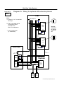
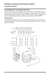
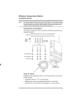
1
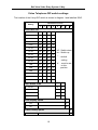
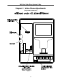
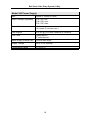
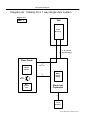
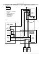
Bell System (Telephones) Ltd.
bellview
Video Entry System
1 Way
Installation & Operation
Manual
PD-010 Issue 2
TABLE OF CONTENTS
General Description . . . . . . . . . . . . . . . . . . . . . . . . . . . . . . . . . . . . . . . . . . . . . . . . 1
Video Telephone (model BV) . . . . . . . . . . . . . . . . . . . . . . . . . . . . . . . . . . . . . . . . . . . . . . . . . 1
Entrance Panel (BVP series) . . . . . . . . . . . . . . . . . . . . . . . . . . . . . . . . . . . . . . . . . . . . . . . . . 1
System Features . . . . . . . . . . . . . . . . . . . . . . . . . . . . . . . . . . . . . . . . . . . . . . . . . . . . . . . . . . . 1
System Operation . . . . . . . . . . . . . . . . . . . . . . . . . . . . . . . . . . . . . . . . . . . . . . . . . . 3
General . . . . . . . . . . . . . . . . . . . . . . . . . . . . . . . . . . . . . . . . . . . . . . . . . . . . . . . . . . . . . . . . . .
Privacy mode (buzzer mute) . . . . . . . . . . . . . . . . . . . . . . . . . . . . . . . . . . . . . . . . . . . . . . . . . .
Monitor Mode . . . . . . . . . . . . . . . . . . . . . . . . . . . . . . . . . . . . . . . . . . . . . . . . . . . . . . . . . . . . .
Systems with extension telephones . . . . . . . . . . . . . . . . . . . . . . . . . . . . . . . . . . . . . . . . . . . .
3
3
3
3
Installation . . . . . . . . . . . . . . . . . . . . . . . . . . . . . . . . . . . . . . . . . . . . . . . . . . . . . . . . 4
Important Safety Information . . . . . . . . . . . . . . . . . . . . . . . . . . . . . . . . . . . . . . . . . . . . . . . . .
Equipment supplied . . . . . . . . . . . . . . . . . . . . . . . . . . . . . . . . . . . . . . . . . . . . . . . . . . . . . . . .
Model 540 Power Supply . . . . . . . . . . . . . . . . . . . . . . . . . . . . . . . . . . . . . . . . . . . . . . . . . . . .
Entrance Panel . . . . . . . . . . . . . . . . . . . . . . . . . . . . . . . . . . . . . . . . . . . . . . . . . . . . . . . . . . . .
Electric Door Release . . . . . . . . . . . . . . . . . . . . . . . . . . . . . . . . . . . . . . . . . . . . . . . . . . . . . . .
Video Telephones . . . . . . . . . . . . . . . . . . . . . . . . . . . . . . . . . . . . . . . . . . . . . . . . . . . . . . . . . .
5
6
6
6
7
7
Commissioning . . . . . . . . . . . . . . . . . . . . . . . . . . . . . . . . . . . . . . . . . . . . . . . . . . . . 8
Video Telephone settings . . . . . . . . . . . . . . . . . . . . . . . . . . . . . . . . . . . . . . . . . . . . . . . . . . . . 8
Picture Adjustment . . . . . . . . . . . . . . . . . . . . . . . . . . . . . . . . . . . . . . . . . . . . . . . . . . . 8
Buzzer mute time . . . . . . . . . . . . . . . . . . . . . . . . . . . . . . . . . . . . . . . . . . . . . . . . . . . . 8
Call Active time . . . . . . . . . . . . . . . . . . . . . . . . . . . . . . . . . . . . . . . . . . . . . . . . . . . . . 8
Disabling the VIEW button . . . . . . . . . . . . . . . . . . . . . . . . . . . . . . . . . . . . . . . . . . . . . 9
Lock Release Adjustment . . . . . . . . . . . . . . . . . . . . . . . . . . . . . . . . . . . . . . . . . . . . . . . . . . . . 9
540 Power Supply . . . . . . . . . . . . . . . . . . . . . . . . . . . . . . . . . . . . . . . . . . . . . . . . . . . 9
Speech Adjustments . . . . . . . . . . . . . . . . . . . . . . . . . . . . . . . . . . . . . . . . . . . . . . . . . . . . . . . . 9
DIP switch settings . . . . . . . . . . . . . . . . . . . . . . . . . . . . . . . . . . . . . . . . . . . . . . . . . . 10
Diagram 1 : Video Phone Adjustments . . . . . . . . . . . . . . . . . . . . . . . . . . . . . . . . . . . . . . . . 11
Troubleshooting . . . . . . . . . . . . . . . . . . . . . . . . . . . . . . . . . . . . . . . . . . . . . . . . . . 12
Fault Finding . . . . . . . . . . . . . . . . . . . . . . . . . . . . . . . . . . . . . . . . . . . . . . . . . . . . . . . . . . . . . 13
Specifications . . . . . . . . . . . . . . . . . . . . . . . . . . . . . . . . . . . . . . . . . . . . . . . . . . . . 16
Model BV Video Telephone . . . . . . . . . . . . . . . . . . . . . . . . . . . . . . . . . . . . . . . . . . . . . . . . .
Model 61 Speech Unit . . . . . . . . . . . . . . . . . . . . . . . . . . . . . . . . . . . . . . . . . . . . . . . . . . . . .
Model BV700 Camera . . . . . . . . . . . . . . . . . . . . . . . . . . . . . . . . . . . . . . . . . . . . . . . . . . . . .
Model 540 Power Supply . . . . . . . . . . . . . . . . . . . . . . . . . . . . . . . . . . . . . . . . . . . . . . . . . . .
17
17
17
18
Cable and Wiring Details . . . . . . . . . . . . . . . . . . . . . . . . . . . . . . . . . . . . . . . . . . . 20
Cable requirement . . . . . . . . . . . . . . . . . . . . . . . . . . . . . . . . . . . . . . . . . . . . . . . . . . . . . . . .
Diagram 2a : Cabling for a 1 way single door system . . . . . . . . . . . . . . . . . . . . . . . . . . . . .
Diagram 2b : Wiring for a 1 way single phone system . . . . . . . . . . . . . . . . . . . . . . . . . . . . .
Diagram 2c : Wiring for systems with extension phones . . . . . . . . . . . . . . . . . . . . . . . . . . .
21
22
23
24
Bell View Video Entry System 1 Way
General Description
The bellview Video Door Entry Telephone System is a high quality, versatile security
product for controlling access to private houses, residential homes, blocks of flats and
offices. The occupant is supplied with an individual video entry telephone, which
enables them to view the person calling at the entrance; to converse with the caller; and
if desired allow them access to the building via an electric lock release.
For a large flat or office, up to 3 extra video entry telephones (extension telephones)
maybe used, enabling the occupant(s) to answer the caller from various locations, such
as a kitchen or bedroom.
Video Telephone (model BV)
This is a slimline, wall-mounting unit, manufactured in high quality impact resistant ABS
plastic. It has a 4" flat tube display with variable contrast and brightness, providing a
high definition, high quality picture.
Entrance Panel (BVP series)
The BVP series aluminium panel is supplied with a flush-fitting back box. Stainless steel
or brass Vandal Resistant panels are also available to order, engraved with the
customers particular requirements. The panel includes a high quality two-way speech
amplifier (model 61) concealed behind a grill, and a solid-state CCD camera (model
BV700) which is protected by a high impact strength lexan window. The camera
includes four, high intensity infrared lamps for illumination of the caller at night time.
System Features
!
!
!
!
!
!
!
!
4" Flat screen monitor
High resolution CCD Camera with infrared lamps
High quality, full-duplex speech amplifier
Privacy function (buzzer mute)
Full privacy of speech
Outputs for fail safe and fail secure locks
Lock release timer
Up to 3 extension telephones
1
Bell View Video Entry System 1 Way
Telephone Controls
Brightness
Contrast
Door Open LED
Mute LED
DOOR
VIEW
CAMERA
Unlocks the door
PORTER
PRIVATE
Camera Select
Monitor entrance
2
Buzzer mute
Bell View Video Entry System 1 Way
System Operation
General
The entrance panel, which includes the camera and speech unit, should be located on
a wall adjacent to the building entrance. A visitor can contact the resident by pressing
the call button on the entrance panel which will call the resident's video telephone
(sounding a buzzer), activating the display and enabling speech. The resident can view
the caller on the video screen and by picking up the handset freely converse with the
visitor. The telephone will remain active for a fixed period (adjustable 30-120 seconds).
If the resident wishes the caller to gain access to the building, the DOOR button can be
pushed while the video telephone is still active; this will operate an electric lock release
on the entrance door for a short period (adjustable, typically 5 seconds).
Privacy mode (buzzer mute)
To avoid disturbance from nuisance calls the resident may push the PRIVATE button
on the video telephone. This will mute the buzzer for a fixed period (adjustable between
1 minute and 10 hours) and illuminate a red indicator lamp. Pushing the button again
will reenable the buzzer and extinguish the lamp.
Monitor Mode
A resident may view the entrance at any time by pressing the telephone VIEW button
(This feature may be disabled if required).
Systems with extension telephones
When a visitor contacts a resident by pressing the call button, all telephones within the
resident’s dwelling will buzz, but the display will not automatically illuminate. The
occupant can then press the VIEW button on the nearest telephone to activate the
display and enable speech as above.
3
Bell View Video Entry System 1 Way
Installation
4
Bell View Video Entry System 1 Way
Important Safety Information
Connections to the 240V AC mains supply must be carried out by a qualified electrician
or similar competent person, and made in accordance with accepted safety practices.
A two-pole switch (as provided by a Consumer Unit or Switch-Fuse) must be included
to isolate both Live and Neutral during Installation or Maintenance. The circuit must be
protected by a fuse or other current-limiting device, rated according to the capacity of
the cable used, up to a maximum of 10A. Use only mains cable to BS6004 or
equivalent, within the following specified limits:
Min
Max
Conductor Diameter
1.0mm (0.8mm2)
2.25mm (4mm2)
Cable Diameter
4.0mm
8.0mm
The M540 power supply is fitted with an internal mains fuse; always replace with the
correct type and rating. The fuse must be of the 20mm glass type, approved to BS EN
60127 or equivalent:
T250mA 250V ( 250mA, 250V, Time delay)
Environment
All equipment except the entrance panel must be placed in a protected indoor
environment.
Video Telephone
The display module of the video telephone has a high voltage circuit (2KV) which
represents a shock hazard. When the top cover of the telephone is removed,
precautions must be taken to avoid contact with this module.
5
Bell View Video Entry System 1 Way
Equipment supplied
BV1 Video System 1 Way Kit
1
BV Video Telephone
1
BVP1 1 Button aluminium panel
1
61 Speech unit (inside the panel)
1
BV700 Camera (inside the panel)
1
540 Power Supply
1
210 Surface Lock Release (fail-secure)
The model 206 lock release can be supplied instead of a 210, if fail-safe operation is
required. Refer to page 7.
Model 540 Power Supply
Read the section called ‘Important Safety Information’ before installing the power
supply.
The power supply must be wall-mounted onto plasterboard, wood or a similar nonconductive material, in a protected indoor environment such as an electrical cupboard.
When fitting the power supply cable (both mains and low voltage) ensure the cable
entry cutouts in the enclosure lid are no larger than necessary for the cable diameter
used and under no circumstances must they be taken beyond the outer cutout zones.
Entrance Panel
Careful consideration should be given to the location of the entrance panel to ensure
the best possible lighting conditions for the camera. In general strong backlighting of the
subject ( by the sun and sky) should be avoided as the contrast between foreground
and background may be too great for the camera. The field of view should contain as
little of the sky as possible, particularly if south facing. A wall or other buildings would
be preferable. If a backlit situation is unavoidable, additional lighting may be necessary
to illuminate the caller and avoid a dark outline image.
The panel should be mounted at an optimum height of 1.6 m, measured between the
ground and camera window.
6
Bell View Video Entry System 1 Way
Electric Door Release
The system is supplied with a Fail-Secure release (FAIL-SECR connections), which
requires power to release the lock and will secure the door upon power failure. Fail-Safe
(FAIL-SAFE connections) lock releases and magnetic locks can also be connected,
requiring continuous power to hold the lock and releasing the door upon power failure.
All of these types can be accommodated providing they are rated at 12V DC with a
maximum current consumption of 0.5A. For lock releases that have different
requirements contact your distributor for further guidance.
When installing lock releases please allow a little movement on the door as operation
will be impaired if fitted too tight.
Video Telephones (Refer to diagram 1)
Refer to the ‘Commissioning’ section for further information.
The model 500PX series telephone (depending on the features required) maybe used
in place of one or more video telephones, if audio only is required.
Up to 3 extension video telephones maybe fitted. If more than 4 video telephones are
required refer to your distributor or the manufacturer for further guidance.
7
Bell View Video Entry System 1 Way
Commissioning
Video Telephone settings (refer to diagram 1)
IMPORTANT:
Single Telephone system
The video telephone must have the terminating slide switch set to 75R, to correctly
terminate the 75S coax cable, refer to diagram 1.
The Auto-Display option must be set to on, refer to page 10.
Systems with Extension Telephones
The most distant telephone must have the terminating switch set to 75R, all others set
to ‘HI’, refer to diagram 1.
The Auto-Display option must be set to off, refer to page 10.
Picture Adjustment
To adjust the BRIGHTNESS and CONTRAST of the picture adjust the two thumbwheel controls at the left hand side of the telephone.
Buzzer mute time
This is he time for which the telephone buzzer will be switched off when the buzzer
mute button is pressed. Set between 1 minute and 10 hours (see SW2 settings,
overleaf).
Call Active time
The telephone active time is the duration for which the telephone remains active
(display and speech) when called. Set between 30 and 120 seconds (see SW2 settings
overleaf).
Auto - Display option
This option allows the display and speech to activate when the telephone is called;
when deselected the telephone will buzz, but display and speech will not activate until
the VIEW button is pressed, refer to page 10.
On systems with extension video telephones, to avoid an excessive power supply
requirement, this option must be disabled.
8
Bell View Video Entry System 1 Way
Disabling the VIEW button
The VIEW button can be enabled/disabled by using the slide switch on the telephone
PCB (BV/2), refer to diagram 1.
CAMERA button
The camera button is only used on systems with more than 1 door.
Lock Release Adjustment
540 Power Supply
Adjust the preset VR1 to the required time, turning clockwise to increase the time.
Shorting ‘Z’ to ‘12V -’ will operate the internal lock relay, for the preset time (and an
audible click heard).
Speech Adjustments
Make sure the Speech Unit is fitted tight against the front grill to avoid possible
feedback effects. The speech volume may be adjusted by carefully applying a small
screwdriver to the back of the Speech Unit; 'A' (speaker symbol) adjusts the speech
level at the panel and 'B' (microphone symbol) adjusts the speech level at the
telephone.
9
Bell View Video Entry System 1 Way
Video Telephone DIP switch settings
The location of the 8 way DIP switch is shown in diagram 1 and labelled ‘SW2'.
DIP Switch Position
Setting
1
2
3
4
1 min
off
off
off
off
2 min
off
off
off
on
3 min
off
off
on
off
5 min
off
off
on
on
8 min
off
on
off
off
10 min
off
on
off
on
15 min
off
on
on
off
20 min
off
on
on
on
30 min
on
off
off
off
45 min
on
off
off
on
1HR
on
off
on
off
2HR
on
off
on
on
3HR
on
on
off
off
5HR
on
on
off
on
8HR
on
on
on
off
10HR
on
on
on
on
5
6
7
8
Buzzer Mute Time
*
* - default
setting
# - must be set
to this
position
5
6
30 sec
off
off
60 sec
off
on
90 sec
on
off
120 sec
on
on
Call / Active Time
*
off - Switch down
on - Switch up
Auto-Display option
7
*
Yes
on
No
off
Video Privacy option
8
#
off
No
10
Bell View Video Entry System 1 Way
Diagram 1 : Video Phone Adjustments
(top cover removed)
IMPORTANT
Refer to page 8
11
Bell View Video Entry System 1 Way
Troubleshooting
12
Bell View Video Entry System 1 Way
Fault Finding
Speech Problems
Low speech volume
!
!
!
!
Constant tone/feedback when in
use.
!
!
!
!
!
!
Speech not audible when phone is
live.
!
!
!
No speech when the phone is
buzzed
!
!
!
Volume adjustment required on the Speech Unit,
see page 9 under SPEECH ADJUSTMENTS.
Speech Unit is not tight against the panel grill.
Panel grill is blocked.
Speech Unit supply voltage low. Check 10V-15V
across 'C' and 'H' on unit, after activating first.
Volume adjustment required on the Speech Unit,
see page 9 under SPEECH ADJUSTMENTS.
‘O’ connection between Speech unit and
telephone open circuit.
Speech Unit is not tight against the panel grill.
Entrance panel and telephone too close together.
The entrance panel is surrounded by reflecting
walls.
Panel grill is blocked.
Low speech volume. To increase refer to page 9
under SPEECH ADJUSTMENTS.
No / low supply to Speech Unit. Check 10V-15V
across 'C' (positive) and 'H' on the unit, after
activating first.
Faulty 'R', 'O', or 'T' line.
Check ‘Auto - Display’ DIP switch setting is ON.
Refer to pages 8 and 10.
No / low supply to ‘+’ and ‘-’ video supply at the
phone. Check 10V - 15V across connections.
Wiring fault on the speech signal connections ‘R’
or ‘T’. ‘R’ carries the phone microphone signal to
the speech unit. ‘T’ the Speech unit microphone to
the phone.
13
Bell View Video Entry System 1 Way
Video Problems
Video picture impaired or
unsynchronised.
!
!
!
!
!
1 or more phone terminating slide switches have
not been set correctly. Refer to page 7.
Poor coaxial cable connection or screen not
connected.
Phone too close to a magnetic field, e.g.
transformer.
Coaxial cable running too close to mains cable.
Coaxial cable is not of 75S type.
Entrance cannot be seen at night.
!
Picture does not appear when the
phone is buzzed.
If the screen lights up:!
!
!
Power not connected to Camera IR night
illumination. Connect '1' to '+' on Camera.
Fault on Video coaxial cable. Check 'M' and 'S'
connections.
No / low supply to Camera. Check 10V-15V across
Camera '+' and '-'.
Coaxial cable is not of 75S type.
If the screen does not light up:!
!
Check ‘Auto - Display’ DIP switch setting is ON.
Refer to pages 8 and 10.
No / low supply to '+' and '-' video supply on
phone. Check 10V-15V present.
14
Bell View Video Entry System 1 Way
Miscellaneous Problems
Telephone will not buzz.
!
!
!
Telephone ‘DOOR’ button does not
operate release.
!
!
!
!
Lock release operates all the time.
!
!
!
Supply voltage low (less than 10V,
any system component).
!
!
Buzzer disabled by PRIVATE button. Check red
telephone LED is off.
Faulty ‘V’,'O' or 'I' line between power supply and
phone. Check 10V - 15V across ‘V’ and ‘O’, and
10V - 15V across ‘I’ and ‘O’ when called.
Faulty panel button.
Telephone is not live.
Fault on 'Z' or 'O' line. Check shorting 'Z' to 0V at
the M540 power supply, when live, operates the
release.
Lock release supply low. Check 10V-15V across
the release with the lock button pressed and the
phone live.
Faulty ‘DOOR’ button on telephone.
If the lock is a 'fail safe' type it has been connected
to 'FAIL SECR'/'fail secure' output. If the lock is a
'fail secure' type it has been connected to 'FAIL
SAFE' /'fail safe' output. Check to see if the
release is inactive when the lock button is pressed
or try swapping the connections over.
‘DOOR’ button stuck down (lock operates only
when live).
'Z' and 'O' lines permanently shorted together.
Short circuit. Disconnect power supply loads and
check the output is 12V - 15V. Systematically
disconnect components one at a time or isolate
floors, etc. until the voltage is correct. Start with
connections close to the Power Supply.
Cable voltage drop too high. Try doubling wires up
with spare cores. Refer to the Cable and Wiring
Details sections.
15
Bell View Video Entry System 1 Way
Specifications
16
Bell View Video Entry System 1 Way
Model BV Video Telephone
Size
180 mm x 245 mm x 75 mm
Fixing
Wall mounted
Supply Voltage
10 V DC min.
15 V DC max.
Current consumption
405 mA maximum active
27 mA maximum idle
Call / Active time
30, 60, 90 or 120 seconds
Buzzer mute time
1 minute min
10 hours max
Model 61 Speech Unit
Size
98 mm x 60 mm x 24 mm
Supply voltage
6 V AC/DC min.
15 V AC/DC max.
Current consumption
100 mA DC max.
140 mA AC max.
Model BV700 Camera
Size
60 mm x 57 mm x 31 mm
Image Device
1/3" CCD
Sensitivity
0.1 lux.
Current consumption
175 mA max. without IR
215 mA max. with IR
Minimum focus
100 mm
Viewing angle
92E (typical)
Supply Voltage
9 V DC minimum
15 V DC maximum
17
Bell View Video Entry System 1 Way
Model 540 Power Supply
Size
236mm x 105mm x 81mm
Output Voltage (regulated)
12.0 V DC min.
13.8 V DC nom.
15.0 V DC max.
Output Current
1.5 A continuous
2.0 A peak (5 minutes max.)
Lock outputs
12 V DC @ 0.5 A max. resistive or inductive
Lock Time
3 seconds min.
27 seconds max.
Mains Supply Internal fuse
T250mA Anti-surge
Supply Voltage
240 V 50 Hz nominal
Temperature Range
0EC to 50EC
18
Bell View Video Entry System 1 Way
Notes
19
Bell View Video System
Cable and Wiring Details
1 Way
Single Door System
CW1
Page 1 of 5
Bell View Video System
1 Way Single Door Systems
Cable Requirement
(Refer to diagrams 2a and 2b.)
Cable types (solid core)
0.5 mm
1.0 mm
Co-ax
Twisted pair, e.g. BT spec CW1308
1.0 mm2 ‘Twin & Earth’
75 Ohm Low loss, e.g. CT100, RG6
Video phones
Total Cable Length
Power (+,-)
50 m
8 @ 0.5 mm [double +, -]
100 m
e.g.
Other connections
2 @ 1.0 mm
Video Signal
75 Ohm Co-ax
4 @ 0.5 mm
75 Ohm Co-ax
A Video phone with a 50 m length requires ; 8 conductors @ 0.5 mm.
Note
Where possible (for optimum speech clarity), a twisted-pair should be used for ‘R’ and ‘O’ connections to the video phone.
Entrance
Connections
No. of Cores
Max
Length
Solid Core
Diameter
Camera + Speech unit + Call Button
5 + 75 Ohm Co-ax
50 m
0.5 mm
Lock Release (up to 0.5 A)
2
25 m
100 m
0.5 mm
1.0 mm
Page 2 of 5
Bell View Video System
Diagram 2a : Cabling for a 1 way Single door system
Page 3 of 5
BV 1
Flat
Video
Phone(s)
6 - 8 (see the
previous page)
Door Panel
*1
75R Co-ax
BV700
Camera
5
Call
Button
M61
Speech
Unit
M540
Power
Supply
Electrical
Cupboard
2
Lock
Release
© 1997 Bell System (Telephones) Ltd.
Bell View Video System
Diagram 2b : Wiring for a 1 way single phone system
Page 4 of 5
Flat
BV 1
I
R
O
T
Z
V
L
Notes
*1 Connect '+' to '1' to activate
IR lamps.
*2 The Co-ax cable can be
connected to either
terminal block.
Video
Phone
+
-
** Use a twisted-pair
(2 conductors).
*2
M S
S M
2
2
**
**
75R Co-ax
Door Panel
Call
Button
M
S
BV700
Camera
Electrical
Cupboard
1
*1 +
Z
+
M61
C
+
- H
-
Speech R
unit
O
+
-
T
+
-
206
210
Lock
Release
Lock
Release
12V
M540
FAIL
SAFE
Power
Supply
FAIL
SECR
Alternative Locks
© 1997 Bell System (Telephones) Ltd.
Bell View Video System
Page 5 of 5
Diagram 2c : Wiring for systems with extension phones
BV 1
Flat
Notes
*1 Connect '+' to '1' to activate
IR lamps.
Next Telephone
75R
I
R
O
T
Z
V
L
*2 The Co-ax cable can be
connected to either
terminal block.
Max. of 4 telephones.
Extension
Video
Phone
Set last
telephone
to 75R all
others to
HI
+
-
*2
** Use a twisted-pair
(2 conductors).
M S
I
R
O
T
Z
V
L
S M
HI
Video
Phone
+
*2
M S
S M
Door Panel
2
2
Call
Button
**
**
75R Co-ax
M
S
BV700
Camera
Electrical
Cupboard
1
*1 +
Z
+
M61
Speech
unit
C
+
- H
-
R
O
T
+
+
-
206
210
Lock
Release
Lock
Release
12V
M540
FAIL
SAFE
Power
Supply
FAIL
SECR
Alternative Locks
© 1997 Bell System (Telephones) Ltd.
c
This product complies with European directive 89/336/EEC on
Electromagnetic Compatibility and Low Voltage Directve 72/23/EEC.
Emissions:
Immunity:
Low Voltage :
Generic BSEN 50081-1
Generic BSEN 50082-1 (IEC801-2, IEC801-6)
Generic BSEN 60950
Bell System (Telephones) Ltd.
Milton Keynes
Made in the United Kingdom