1
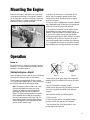
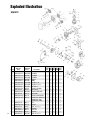
® ENGINE INSTRUCTION MANUAL 4 3 5 2 7 1 6 G26 Air G26/G231 Marine G26/G231 Heli G38 G62 GT80 Twin G45 1 2 3 4 5 6 7 Table of Contents Introduction . . . . . . . . . . . . . . . . . . . . . . . . . . . . . . . . . . . . . . . . . . . . . . . . . . . . . . . . . . . . . . . . . . . . . . . 3 Safety Instructions . . . . . . . . . . . . . . . . . . . . . . . . . . . . . . . . . . . . . . . . . . . . . . . . . . . . . . . . . . . . . . . . . . 3 Support Equipment . . . . . . . . . . . . . . . . . . . . . . . . . . . . . . . . . . . . . . . . . . . . . . . . . . . . . . . . . . . . . . . . . 4 Mounting the Engine . . . . . . . . . . . . . . . . . . . . . . . . . . . . . . . . . . . . . . . . . . . . . . . . . . . . . . . . . . . . . . . . 5 Operation . . . . . . . . . . . . . . . . . . . . . . . . . . . . . . . . . . . . . . . . . . . . . . . . . . . . . . . . . . . . . . . . . . . . . . . . . 5 Break In . . . . . . . . . . . . . . . . . . . . . . . . . . . . . . . . . . . . . . . . . . . . . . . . . . . . . . . . . . . . . . . . . . . 5 Starting the Engine, Aircraft . . . . . . . . . . . . . . . . . . . . . . . . . . . . . . . . . . . . . . . . . . . . . . . . . . . . 5 Starting the Engine, Heli & Boat . . . . . . . . . . . . . . . . . . . . . . . . . . . . . . . . . . . . . . . . . . . . . . . . . . 6 Stopping the Engine . . . . . . . . . . . . . . . . . . . . . . . . . . . . . . . . . . . . . . . . . . . . . . . . . . . . . . . . . . . 6 Carburetor Adjustment . . . . . . . . . . . . . . . . . . . . . . . . . . . . . . . . . . . . . . . . . . . . . . . . . . . . . . . . . 6 Engine Care and Maintenance . . . . . . . . . . . . . . . . . . . . . . . . . . . . . . . . . . . . . . . . . . . . . . . . . . . . . . . . . 7 Recommendations . . . . . . . . . . . . . . . . . . . . . . . . . . . . . . . . . . . . . . . . . . . . . . . . . . . . . . . . . . . 7 Servicing the Engine . . . . . . . . . . . . . . . . . . . . . . . . . . . . . . . . . . . . . . . . . . . . . . . . . . . . . . . . . . 7 Disassembly . . . . . . . . . . . . . . . . . . . . . . . . . . . . . . . . . . . . . . . . . . . . . . . . . . . . . . . . . . . . . . . . . 7 Assembly . . . . . . . . . . . . . . . . . . . . . . . . . . . . . . . . . . . . . . . . . . . . . . . . . . . . . . . . . . . . . . . . . . 8 Charts . . . . . . . . . . . . . . . . . . . . . . . . . . . . . . . . . . . . . . . . . . . . . . . . . . . . . . . . . . . . . . . . . . . . . 9 Troubleshooting Guide for Gasoline Engines . . . . . . . . . . . . . . . . . . . . . . . . . . . . . . . . . . . . . . . . . . . . . 11 Propeller Chart . . . . . . . . . . . . . . . . . . . . . . . . . . . . . . . . . . . . . . . . . . . . . . . . . . . . . . . . . . . . . . . . . . . . 12 Engine Specifications . . . . . . . . . . . . . . . . . . . . . . . . . . . . . . . . . . . . . . . . . . . . . . . . . . . . . . . . . . . . . . . 13 Exploded Illustration . . . . . . . . . . . . . . . . . . . . . . . . . . . . . . . . . . . . . . . . . . . . . . . . . . . . . . . . . . . . . . . 14 G26/G231 . . . . . . . . . . . . . . . . . . . . . . . . . . . . . . . . . . . . . . . . . . . . . . . . . . . . . . . . . . . . . . . . . 14 G38 . . . . . . . . . . . . . . . . . . . . . . . . . . . . . . . . . . . . . . . . . . . . . . . . . . . . . . . . . . . . . . . . . . . . . . 16 G45 . . . . . . . . . . . . . . . . . . . . . . . . . . . . . . . . . . . . . . . . . . . . . . . . . . . . . . . . . . . . . . . . . . . . . . . 17 G62 . . . . . . . . . . . . . . . . . . . . . . . . . . . . . . . . . . . . . . . . . . . . . . . . . . . . . . . . . . . . . . . . . . . . . . . 18 GT80 . . . . . . . . . . . . . . . . . . . . . . . . . . . . . . . . . . . . . . . . . . . . . . . . . . . . . . . . . . . . . . . . . . . . . . 19 Warranty Information . . . . . . . . . . . . . . . . . . . . . . . . . . . . . . . . . . . . . . . . . . . . . . . . . . . . . . . . . . . . . . . . 20 Warranty Repairs . . . . . . . . . . . . . . . . . . . . . . . . . . . . . . . . . . . . . . . . . . . . . . . . . . . . . . . . . . . . 20 Non-Warranty Repairs . . . . . . . . . . . . . . . . . . . . . . . . . . . . . . . . . . . . . . . . . . . . . . . . . . . . . . . 20 Registration Form . . . . . . . . . . . . . . . . . . . . . . . . . . . . . . . . . . . . . . . . . . . . . . . . . . . . . . . . . . . . 21 Very Important Failure to read and follow these instructions before you proceed may result in engine damage and the voiding of your warranty! Introduction Congratulations on purchasing a Zenoah® engine. Cared for properly, these high-quality, finely crafted engines will offer many years of reliability. This instruction manual has been developed to ensure optimum performance from the Zenoah engine you have purchased. It’s important that the instructions are read thoroughly prior to mounting and running the engine. Safety Instructions This manual describes the engine’s features and functions. For specific information on mounting, see the instruction manual included with the model airplane, helicopter or boat in which you intend to install the engine. This model engine will give you considerable pleasure, satisfaction and performance if you strictly follow these safety instructions and take heed of the warnings as to the engine’s safe and proper use. This engine has more than enough power to cause harm if misused or if the safety precautions are not observed. Always 1. Use genuine parts for replacement. 2. Check the propeller, rotor (helicopter) or screw propeller (boat) prior to each time the engine is used. If nicked, scratched, cracked or damaged in any way, replace it with a new one. 3. Use the correct size and pitch of propeller for your engine; refer to the propeller chart in this manual. 4. It is extremely important to balance the propeller prior to installation of the engine. Failure to do so may cause damage to the Zenoah engine and/or the airframe. Securely tighten the propeller nut against the washer and propeller. 5. Inspect the tightness of the propeller nut prior to each flight. 6. Keep your face and body away from the path of the propeller blades when starting or running your engine. 8. Make all carburetor adjustments from behind the propeller. 9. To stop the engine, the black lead wire from the coil should be grounded to the engine body, or use the throttle linkage to shut off the air by closing the throttle valve completely. Do not use hands, fingers or any other part of the body to stop the propeller. Do not throw any object into a propeller to stop it! 10. Ensure that all spectators, especially children, are at least 20 feet away when you start running the engine. 11. Make sure your fuel is kept in a safe place well away from sparks, heat or anything that could ignite the fuel. Recommendations 1. Use safety glasses or goggles when starting and running your engine. 2. Do not run the engine in the vicinity of loose gravel or sand. The propeller may throw such materials into your eyes. The engine could also ingest these harmful materials. 3. Avoid loose clothing when operating your model engine, as it could become entangled in the propeller, creating the possibility of bodily harm. All loose objects (screwdrivers, pencils, nickel cadmium glow drivers, etc.) should be removed from your pockets so that they do not fall into the propeller. 7. Use a thickly padded glove when hand starting the engine. Safety Instructions (continued) Caution Disassembly 1. Model engines get very hot while running. Do not attempt to handle them until they have cooled. The Zenoah engine can be disassembled or reassembled without any specific difficulties. Refer to the Engine Maintenance Section for specific instructions on these procedures. If you need service to your Zenoah engine, please send it to the authorized service center at the . following address: 2. Always run your model engines in a well-ventilated area. Similar to automotive engines, model engines produce harmful carbon monoxide fumes. 3. Never modify the flywheel. 4. Check the flywheel. If it’s damaged, replace it with a new one. 5. When mixing the fuel or operating the engine, do so in a well-ventilated area 6. Remember that model engines produce a substantial amount of power, more than enough to seriously injure people and/or do considerable damage to property. Always use common sense, skill and constant observance of safety precautions. ® Horizon Hobby, Inc. Attention: Zenoah Service 4105 Fieldstone Road Champaign, IL 61822 Phone: (217) 355-9511 Engine Parts Identification It’s important to be able to identify the parts of your Zenoah engines. Inside this manual you will find an exploded view of Zenoah engines, as well as a chart including part numbers and descriptions. This will assist you in easily and rapidly identifying the respective parts of your Zenoah engine. Support Equipment The following items are not included with your Zenoah engine but are necessary for operation. Fuel—Mix gasoline and 2-stroke gas compatible oil at a mixing ratio of 25–40:1. Note: Be sure to use a gasoline-resistant fuel tubing (do not use any silicone rubber tube). Never use any alcohol fuel or alcohol-added fuel as this will damage the rubber part of the carburetor. Propeller—Refer to the Propeller Selection Chart located on Page 8 to determine the best initial propeller for your particular application. Manual or Electric Starter—For manual starts, a chicken stick is highly recommended. Never use your fingers to start any model engine as you could be injured. If you must hand-start a gasoline engine, be sure to protect your hand with a heavily padded glove. There are a variety of heavy-duty electric starters on the market that can be used. Evolution Oil EVOX1001Q Mounting the Engine Make sure the engine is mounted on the aircraft using aircraft grade plywood that’s at least 6mm in thickness for the G26 engine, and 10mm in thickness for the G38 through GT80 twin, or a mount of equivalent strength. Make sure it’s firmly mounted with 4 bolts. 1. Be sure to set flat washers or a metal plate on the reverse side of the mount to prevent the bolts from sinking into the mount. Periodically check the engine mount for loose bolts. 2. Since the engine is equipped with a floatless carburetor with a diaphragm pump, the direction of the cylinder and position of the fuel tank can be freely selected. 3. If the engine is mounted on a shock (rubber) mount placed between the engine and the firewall for antivibration, check the hardness of the rubber, making sure it’s not too soft, in order to avoid excessive vibration during engine operating rpms. Note carefully if the engine is vibrating at idle, as excessive vibration can result in erratic engine operation due to overflow at the carburetor. 4. It is suggested that the bolts for the muffler be coated with threadlock when mounting the muffler to the engine. Operation Break In Coil No specific break in is required. The engine is gradually broken in as it is used, and the output power increases gradually as the engine breaks in. Starting the Engine—Aircraft Before attempting to start the engine, be sure to read through all the steps for starting the engine as outlined below: Zenoah engines are equipped with the ultra compact C.D.I. type flywheel magneto ignition system and should be started according to the following procedure: Note: The magneto system is timed in such a way that when the compression stroke starts (refer to Figure 1-A) sparks are never produced on the spark plug, no matter how fast the propeller is flipped. The correct starting procedure is to quickly flip the propeller when the edge of the magnet on the rotor is approaching the coil (Figure 1-B). This means that the propeller should be quickly flipped at about 90 degrees in crank angle before the compression stroke is about to start. Magnet Fig 1-A Fig 1-B 1. Make sure the spark (glow) plug(s) are installed and tightened. Check the condition of the plug cap for cracks or breaks. 2. Be sure the propeller is properly secured. 3. Make sure the fuel tank line(s) are properly connected. The main line should be connected to the carburetor spray bar. 4. Be certain the mufflers are installed properly. 5. Fill the fuel tank. 6. Choke the engine and turn the propeller through a few times until the fuel appears at the carburetor. 7. Set the throttle valve at the idle position or at the position slightly open from idle. Operation (continued) 8. Quickly flip the propeller in a counterclockwise direction. (See note on previous page) We recommend the Zenoah ZEN20000 Kill Switch. Refer to the example shown in the following diagram. 9. The engine should start after a few flips of the propeller. 10. Be sure to open the choke when the initial firing of the engine is heard. Red Lead 11. When the choke is opened, be sure to close the throttle valve to a position near the idle position before the next flipping of the propeller is attempted. Black Lead CAUTION: If the engine is started when the throttle is wide open, a great thrusting force will be generated, which can be very dangerous. 12. If you do not use a chicken stick to start the engine, be sure to wear a thick glove when flipping the propeller and use all fingers, except the thumb, for the flipping operation. 13. Do not over-rev the engine. These engines are designed to develop maximum output with the standard muffler and the recommended propeller size. Please refer to the propeller chart on page 10 to confirm the proper propeller for the applicable Zenoah engine. ® Kill Switch Engine Body Ground Carburetor Adjustment The carburetor is provided with three adjustment screws, which are factory set to the best (approximate) positions. They may need minor adjustment, depending upon the temperature, humidity, atmospheric pressure (altitude), etc., of the area where the engine is being used. Starting the Engine—Helicopter and Boat 1. Fill the tank with fuel. High-Speed Needle Low-Speed Needle 2. Push the priming bulb located on the carburetor until fuel appears in the priming bulb (for helicopter). 3. Choke the engine and open the throttle valve approximately 1/3–1/2 of the full open position. 4. Quickly pull the starter cord until the initial firing of the engine is heard. 5. When the initial firing is heard, open the choke, set the throttle valve at the idle position or at the position slightly open from the idle position and quickly pull the starter cord a few more times until the engine starts. 6. For helicopter operation, you should adjust the rotorpitch to obtain a 9,000 to 10,000 rpm of the engine at full throttle operation. Stopping the Engine The ability to shut down the engine in an emergency is extremely important. For stopping the engine, the black lead wire from the coil should be grounded to the engine body, or the throttle valve should be closed completely. Installation of a “stop” or “kill” switch is recommended. Idle Screw 1. Start the engine without making any adjustments. 2. Make adjustments only when the engine shows signs of inefficient operation. 3. Standard settings of each needle is as follows: a. Low-Speed Needle: 11/8 plus/minus 1/4 b. High-Speed Needle: 13/8 plus/minus 1/4 Idle Screw: Turning this screw clockwise increases the idling rpm. Turning it counterclockwise decreases the idling rpm. Low-Speed Needle: This is the fuel adjust screw (not the air screw). Turning this needle clockwise makes the gas mixture leaner, and turning it counterclockwise makes it richer. Operation (continued) High-Speed Needle: Turning this needle clockwise makes the gas mixture leaner, and turning it counterclockwise makes it richer. Set this needle at a position which is 1/4 open from the maximum rpm position while the aircraft is on the ground. When the engine has just started and is not warm enough, there may be insufficient acceleration and the engine may die. Be sure to allow the engine to warm up at idle for a few minutes before conducting normal operation. Note: Do not tighten the high and low speed . needles too tightly. Engine Care and Maintenance Recommendations • Engine oil To extend the life of your Zenoah® engine, the following is recommended: • Washing gasoline 1. Use an Evolution quality 2-stroke oil mixed at 32 to 1. • Scraper 2. Use the recommended spark plugs. • Cloth 3. Use the proper propeller size and balance the . propeller prior to use. The engine can be disassembled or reassembled without any specific difficulties, but note the following: 4. Always adjust the engine to a slightly rich setting. For disassembling, the special tools shown in the parts list are required (stopper, puller assembly), in addition to general tools. Be sure to use a new gasket when the crankcase and cylinder have been disassembled. 5. For long-term storage, make sure there is no fuel left in the tank or the engine. Remove the spark plug(s) and apply several drops of high-quality oil (e.g., Marvel Air Tool Oil) to the top of the engine and into the spark plug hole. Rotate the crankshaft several times. Store the engine in the box it came in or on the airplane with the nose down in order to keep oil in the bearings. • Brush Note: Because the crankshaft is of the assembly type, do not disassemble, hit or twist its end. Disassembly Servicing the Engine 1. Dismount the engine from the model. Required Tools 2. Remove the carburetor and insulator carefully without damaging the gasket. • Regular screwdriver • Phillips screwdriver • Hexagonal wrench (4mm/5/32") • Open wrench (19mm/3/4") • Plastic hammer • Thickness gauge 3. Remove the muffler. 4. Remove the spark plug and ignition module. 5. Remove the propeller hub. 6. Remove the rotor (flywheel). If it cannot be detached, use a plastic hammer and tap the part lightly. • Threadlock (Blue Threadlock Z-42 or equivalent) a. Screw the stopper in place of the spark plug, then turn the rotor counterclockwise until the piston touches the stopper. Take care, as it can cause damage to the piston or connecting rod if the stopper is not screwed into the bottom. • Lithium grease b. Loosen and remove the rotor securing nut. • Tapered round rod • Liquid gasket (Permatex or equivalent) Engine Care and Maintenance (continued) c. Remove the rotor by using the puller. Do not hit the crankshaft with the plastic hammer, as this can increase the runout of the shaft. 7. Remove the mounting plate. 8. Remove the four bolts from the crankcase. 9. Tap around the case fitting side gently with the plastic hammer and slowly separate the crankcase from the cylinder block. 10. Pull out the crankshaft with the piston, bearings, and other parts attached. 8. Put the piston in the cylinder, with the piston’s arrow facing in the exhaust port direction. Set the crankshaft to the cylinder block. Then, fit the oil seal to the cylinder block. The snap ring joint should be set vertically to the cylinder. 9. Fit the crankcase to the cylinder block and tighten the bolts. 11. Remove the Woodruff key from the crankshaft. 10. Check that the crankshaft can be smoothly turned by hand. 12. Remove the oil seal, snap ring and bearings. 11. Put back the Woodruff key. 13. Remove the circlip and pull out the piston pin. 12. Replace the rotor (flywheel), fitting it to the Woodruff key. Tighten the hub nut after having applied threadlock (Blue Threadlock Z-42 or equivalent) to the threads. 14. Remove the thrust washers and needle bearing from the smaller end of the connecting rod (G38). 15. Remove the piston ring. 16. Wash each part. Check for abrasion and damage, and replace any part that is defective. Assembly (G38) 1. Apply engine oil (SAE #30) to the inside of the cylinder and to the needle bearings on the larger end of the connecting rod. 2. Fit the piston ring to the piston. 3. Mount the needle bearing and thrust washer (with its oil slot facing inside) to the smaller end of the connecting rod and apply engine oil (SAE #30). 4. With the arrow on the top of the piston facing the straight side (opposite side to the propeller) of the crankshaft, fit the piston to the top of the connecting rod and insert the piston pin with its blank end to the exhaust port side. 5. Fit the circlip. 6. Fit the bearings, snap ring and oil seal to the crankshaft. (Apply lithium grease to the lip area of the oil seal and fit it, paying attention to its direction.) 7. Wipe the contact surfaces of the cylinder block and crankcase, and apply liquid gasket (Permatex or equivalent). 13. Apply threadlock (Blue Threadlock Z-42) to the muffler bolts and mount the muffler. 14. Apply threadlock (Blue Threadlock Z-42) to the ignition module setscrews and fix the coil temporarily. 15. Set the rotor (flywheel) so that the magnet is located on the opposite side of the module (G38). Place a thickness gauge between the core of the module and rotor (flywheel) and adjust the clearance to 0.25 ^ 0.35 mm (0.01 ^ 0.014 in). Then tighten the setscrews after having applied threadlock (Blue Threadlock Z-42) to them. 16. Using a new gasket, fix the insulator with screws to which threadlock (Blue Threadlock Z-42) has been applied. 17. Using a new gasket, mount the carburetor with screws, paying attention to its mounting direction. 18. Tighten the mounting plate, using screws with threadlock (Blue Threadlock Z-42) applied. 19. Install the spark plug. Note: Disassembly and assembly steps were written using a G38 engine as an example, but they apply to all engines. Engine Care and Maintenance (continued) Maintenance Chart Items Before Use Every 25 hours Every 100 hours Leakage, Damage/Crack Losing Speed Check/Adjust Air-cleaner (PUH) Check/Cleaning Spark Plug (gap) Check/Adjust Cylinder (barrel) Check/Cleaning Piston, Ring Check/Cleaning Muffler & Bolt Check/Cleaning Bearings Check/Cleaning Crankshaft Rotor Action Check P P P P P P P P P P P P P P P P Check/Alignment Check Propeller Hub (PU) Check/Alignment Water Jacket (PUM) Check/Leakage P P P P P P P P P P P P P Note Replace if necessary ì ì ì ì ì ì ì ì ì Specifications & Technical Data Items Unit G260PU G260PUM G260PUH G231PUM G231PUH Type –– Air Cooled Water Cooled Air Cooled Water Cooled Air Cooled Bore x Stroke mm 34 x 28 Displacement 3 cm Effective Compression Ratio Carburetor 25.4 ë ë ë ë –– 8.4 ë ë Type (Walbro) WT-645 Venturi (mm) 12.7 Air Cleaner WT-644 ë WT-677 ë 22.5 ë ë ë ë 32 x 28 WT-644 ë WT-677 ë –– –– –– Hand Flipping or Electric Motor Recoil Starter Type CDI BTDC/rpm 28/7000 STD RZ7C Option –– CMR8H/7H –– CMR6H/7H –– Idle Speed rpm 1800 APC 18 x 8 3500 3000 3500 3000 Max. Power rpm 1.62/12000 2.16/12000 1.71/13000 2.09/12000 1.58/13000 Min. Torque rpm 1.48/9000 1.94/9500 1.42/9500 1.79/10000 1.34/9000 760 720 700 1.77 (*1.57) 1.55 1.78 (*1.58) Starting Ignition Spark Plug ë 30/7000 ë Fuel Consumption cc 790 710 Weight kg 1.69 (* 1.52) 1.54 Dry Type –– Dry Type ë ë ë ë ë ë ë ë ë ë ë ë Engine Care and Maintenance (continued) Maintenance Specifications Items Standard Limit Standard Limit Measuring Device Bore (mm) ø34 Plating damaged ø32 Plating damaged Eye Checking Diameter (mm) ø33.97 ø33.87 ø31.97 ø31.87 Micro Meter Piston Ring Groove Width (mm) 1.01 1.11 1.01 1.11 Thickness Gauge Piston Ring Hole (mm) ø8.01 ø8.05 ø8.01 ø8.05 Cylinder Gauge Clearance Between Piston and Cylinder (mm) 0.03–0.05 0.15 0.03–0.05 0.15 Micro Meter Cylinder Gauge Clearance Between Groove and Piston Ring (mm) 0.02–0.04 0.1 0.02–0.04 0.1 Thickness Gauge End Gap (mm) 0.05–0.25 0.5 0.05–0.25 0.5 Thickness Gauge Width (mm) 0.98 0.93 0.98 0.93 Micro Meter Piston Pin Diameter (mm) ø8 ø7.98 ø8 ø7.98 Micro Meter Connecting Rod, Small End (mm) ø11 ø11.05 ø11 ø11.05 Cylinder Gauge Crankshaft Dia. at Main Bearing (mm) ø12 ø11.98 ø12 ø11.98 Micro Meter Eccentricity (mm) –– 0.07 –– 0.07 Dial Gauge Axial Play (mm) –– 0.5 –– 0.5 Thickness Gauge Main Bearing –– Gritty or Has Flat Spot –– Gritty or Has Flat Spot –– Cylinder Piston Piston Ring 10 Remarks At the skirt end and the right angle to the piston pin When inserted in a new cylinder Troubleshooting Guide for Gasoline Engines Generally speaking, there are very few things that will keep today’s modern engines from starting. Use good quality “fresh” fuel and make sure that good plugs are installed. Should the engine fail to start after these items are verified, refer to the charts on the following page. a) The engine does not start. The crankshaft does not rotate Seizure, intrusion of a foreign substance The crankshaft rotates The fuel has not been fed to the carburetor Disassemble and repair Clogging inside the carburetor Disassemble and clean Clogging of the fuel piping Clean The fuel has been fed to the carburetor No compression (normally 7 kg/cm2 99.5 psi or more) Compression adequate The spark plug does not spark Loosened Tighten further spark plug Replace Abrasion or damage of the cylinder, piston, or piston ring The spark plug does spark Remove the spark plug and dry it The carburetor has not been properly Readjust adjusted The fuel is not Replace suitable The Stop switch has Turn on been turned off Wiring is disconnected Repair The spark plug is defective Replace The ignition module is defective Replace The air gap is too large Adjust Adjust The spark plug gap is too large Wet plug b) The engine stops by itself It suddenly stops The crankshaft does not rotate or is abnormally heavy The crankshaft rotates See a) The plug cap has come off Wiring disconnection Put back Spark plug bridge Use a standard plug Use clean fuel The Stop switch has been turned off It slows down and stops Out of fuel Not out of fuel Repair Turn on Refuel The fuel is not fed to the carburetor Water is mixed in the fuel See a) Replace c) Lower power output Overheating The carburetor has not beeen properly adjusted Air suction from a carburetor joint or oil seal Abrasion of the piston ring The fuel is not suitable Clogging of the muffler or exhaust port due to carbon The spark plug heat range is not proper Readjust Repair Replace Replace Clean Replace d) The engine does not stop Overheating The Stop switch is defective Switch wiring is disconnected See c) Repair Repair 11 Troubleshooting Guide for Gasoline Engines (continued) In the event that none of the above procedures result . in the engine running properly, contact our service department for suggestions at: Horizon Hobby, Inc. 4105 Fieldstone Road Champaign, IL 61822 Phone: 217-355-9511 (M–F 8:00–5:00 CST) Propeller Chart This chart enables you to select the best propeller for initial setup of your Zenoah engine. Remember, it’s imperative to balance each propeller prior to installation onto your Zenoah engine. Failure to do so may cause unwanted vibration in your aircraft. EnginePropeller G26A 16x8 @ 8,700 G231 Heli G26 Heli Adjust pitch of rotor to obtain . 9,000–10,000 rpm of the . engine at full throttle G26 Marine 12 G231 Marine Diameter = 65–75mm Pitch ratio 1.9–1.4mm G38 Gas 18x10 @ 7,300 G45 Gas 20x10 @ 7,200 G62 Gas 22x10 @ 7,200 GT80 Gas 22x12 @ 7,200 24x10 @ 7,200 Note: All recommendations are based on engines using APC brand props. Engine Specifications Outside Dimensions (mm) Items Length Width Height Operating RPM Optional Mufflers G26A 139mm 105mm 181mm 2,000–10,000 BIS07123 G26M 139mm 105mm 181mm 2,000–10,000 G26H 139mm 105mm 181mm 2,000–10,000 — — G231 HELI 142mm 105mm 181mm 3,000–11,000 G231 MARINE 142mm 105mm 181mm 3,500–15,000 G38 — — 170mm 130mm 215mm 2,000–9,000 BIS07138 G45 152mm 130mm 185mm 2,000–10,000 BIS07145 G62 162.5mm 140mm 185mm 2,000–10,000 BIS07163 GT80 191.5mm 257mm 190mm 1,800–10,000 BIS07445/6 Specifications Displacement (cu in) Bore (in) Stroke (in) Weight (oz) K (ISO) HP (H/M) Carb (Walbro) G26A/M/H 1.55 1.41 1.1 54/57 M8x1.25/6x1 2.4 WT645/WT644/WT677 G231M/H 1.4 1.3 1.1 54 M8x1.25 2.2 WT644/WT643 G38 2.3 1.5 1.3 67 M10x1.25 2.2 WT338/WTA-6A G45 2.74 1.69 1.22 74 8x1 3.3 HDA-48D G62 3.8 1.9 1.4 73 10x1 4.75 HDA-48D GT80 4.8 1.60 1.22 126 10x1.25 6 WJ-64 * w/spring starter 13 Exploded Illustration G26/G231 14 New Zen Key #Part # 14 1-1 1- 2 2-1 2-2 3 4 5 6 7 8 9 10 11 12 13 14 15 16 17 18 19 20 21 Out of Date Part # ZENT207512110 ZEN2601 ZENT207012111 ZEN2301RCA ZENT207612110 ZEN2601M ZENT207812110 ZEN23102M ZENT207612210 ZEN2603M ZEN0785100515 ZEN2304M ZEN0700013040 ZEN23105M ZENT207612320 ZEN23106M ZEN116012330 ZEN2307M ZENT207513120 ZEN23108 ZEN331012281 ZEN2309 ZENT207513150 ZEN2305RC ZEN114813162 ZEN23111 ZENT207514120 ZEN23112 ZENT207521100 ZEN23114 ZEN262921130 ZEN6213 ZENT207521140 ZEN23116 ZEN216921210 ZEN3828 ZEN33301412 ZEN2318 ZEN0406502812 ZEN2319 ZEN0603406001 ZEN2320 ZEN185021220 ZEN2321M Quantity Per Unit G260G260G260G231G231 DescriptionPUPUMPUHPUMPUH CYLINDER CYLINDER CYLINDER CYLINDER JACKET JOINT O-RING 3 x 40 O-RING 1.5 x 15.5 BOLT M3 x 8 GASKET, CYLINDER BOLT M5X20 GASKET, INSULATOR INSULATOR GASKET, CARBURETOR CRANKCASE, COMPLETE CRANKCASE, REAR CRANKCASE, FRONT PIN GASKET SEAL, 12 x 22 x 7 BEARING Snap Ring BEARING SEAL, 12 x 28 x 7 1 – – – – – – – – 1 6 1 1 1 1 1 1 3 1 1 2 1 1 – – – 1 – 1 2 1 1 2 1 6 1 1 1 1 1 1 3 1 1 2 1 – 1 1 – – – – – – – – 1 6 1 1 2 1 1 1 3 1 1 2 1 1 – – – – 1 1 2 1 1 2 1 6 1 1 1 1 1 1 3 1 1 2 1 – 1 – 1 – – – – – – – 1 6 1 1 2 1 1 1 3 1 1 2 1 1 – Exploded Illustration G26/G231 continued Quantity Per Unit New ZenOut of Date G260G260G260G231G231 Key #Part # Part # DescriptionPUPUMPUHPUMPUH 22 23-1 23-2 24-1 24-2 25-1 25-2 26 27 28 29 30 31 32 33 34 35 36 37 38-1 38-2 39 40 41 42 43 44 45 46 47 48 49 50 51-1 51-2 51- 3 52 53 54 55 56 57-1 57-2 58-1 58-2 59-1 59-2 60 61 62 ZEN0125230530 ZEN2322 ZENT208841110 ZEN2623 ZENT207041110 ZEN2320RC ZENT208841210 ZEN2624 ZENT207041210 ZEN2321RC ZEN2625 ZEN160041310 ZEN2322RC ZEN110141310 ZEN2323RC ZEN126041320 ZEN550041410 ZEN2324RC ZEN110141340 ZEN2325RC ZENT207542000 ZEN23129 ZEN2330 ZEN115574110 ZEN2331 ZEN026210516 ZEN2327RC ZEN165043230 ZEN116075210 ZEN2333M ZEN2634 ZEN186175101 ZEN2341 ZEN026330414 ZEN100043240 ZEN2328RC ZEN114043250 ZEN2337 ZEN6236 ZEN262971210 ZEN2339M ZEN116071211 ZEN115571110 ZEN2354 ZEN6241 ZEN026030422 ZEN2341 ZEN026330414 ZENT207572210 ZEN2638 ZEN190072120 ZEN6239 ZEN262971311 ZEN6237 ZENT207073110 ZEN26451 ZEN2667M ZEN369991975 ZEN2648 ZEN026330555 ZEN2647 ZEN114283110 ZEN848ES08300 ZEN2649A ZENT207782000 ZEN23150H ZEN2650 ZEN2650 ZENT207581000 ZEN2651 ZENT207681000 ZEN23151 ZENT207781000 ZEN23152 ZEN115243260 ZEN2359 ZEN115243281 ZEN2360 ZEN115243290 ZEN2361 ZEN2362 ZEN335053410 ZEN23156 ZEN114013141 ZEN0125230550 ZEN2357 ZEN0125230560 ZEN2357H ZEN2358 ZEN026330408 ZEN2358H ZEN026390416 ZENT207515110 ZEN2655 ZEN114808010 ZEN2355 ZEN2366 ZEN114515412 ZEN115815420 ZEN2367 ZENT303991310 ZEN23124RC ZEN20010 ZEN20010 ZEN20005 ZEN20005 BOLT, M5 x 30 PISTON PISTON RING RING PISTON PIN PISTON PIN SNAP RING BEARING WASHER CRANKSHAFT, COMPLETE MOUNT, PLATE SCREW, M5 x 16 NUT, M8 PULLEY RECOIL ASSEMBLY SCREW, M4 x 14 KEY SHIM COIL, (GREY) COIL, (RED) ROTOR SCREW M4 x 22 SCREW M4 x 14 PLUG CAP SPRING COIL SPARK PLUG RZ7C SPARK PLUG MARINE ONLY SCREW, M5 x 55 SPACER, 5 x 10 x 1.6 AIR TUNNEL (VENTURI) CLEANER ASSEMBLY TUBE CARBURETOR ASSY WT-645 CARBURETOR ASSY WT-644 CARBURETOR ASSY WT-643 HUB STUD WASHER NUT, M8 GASKET, MUFFLER BOLT, M5 x 502 BOLT, M5 x 60 SCREW, M4 x 8 SCREW, M4 x 16 MUFFLER MUFFLER SPACER SPACER SOCKET piston stopper, option for G260PUA/M/H Piston Stopper 4 1 – 1 – 1 – 2 1 2 1 1 3 1 – – – 1 1 1 – 1 2 2 1 1 1 1 – 2 2 1 – 1 1 – – 1 1 1 1 1 – – 1 – 1 – – – 1 1 4 1 – 1 – 1 – 2 1 2 1 1 3 – 1 1 4 1 1 – 1 1 2 2 1 1 1 1 1 2 2 1 – 1 – 1 – – – – – – – – – – – – – – 1 1 4 1 – 1 – 1 – 2 1 2 1 1 3 – 1 1 4 1 1 – 1 1 2 2 1 1 1 1 – 2 – – 1 – – – 1 – – – – 2 – 2 – 1 – 1 1 1 1 1 4 – 1 – 1 – 1 2 1 2 1 1 3 – 1 1 4 1 1 – 1 1 2 2 1 1 1 1 1 2 2 1 – 1 – 1 – – – – – – – – – – – – – – 1 1 4 – 1 – 1 – 1 2 1 2 1 1 3 – 1 1 4 1 1 – 1 1 2 2 1 1 1 1 – 2 – – 1 – – – 1 – – – – 2 2 – 1 – 1 1 1 1 1 15 Exploded Illustration (Standard Accessory for G380PU) G38 Index No. 1 2 3 4 5 6 11 12 13 14 15 16 17 18 19 20 21 22 23 24 25 26 27 28 29 30 31 32 33 34 35 16 New ZEN Part No. ZEN337812111 ZEN333014111 ZEN333014121 ZEN026020520 ZEN333014132 ZEN337815000 ZEN284115210 ZEN333015220 ZEN337821110 ZEN0125230540 ZEN029220510 ZEN312013510 ZEN313013520 ZEN334041113 ZEN334041211 ZEN330441310 ZEN331041320 ZEN165041510 ZEN331041410 ZEN337842000 ZEN603006201 ZEN165021220 ZEN0406503212 ZEN216921210 ZEN126043240 ZEN165043230 ZEN029020820 ZEN0164120812 ZEN260951110 ZEN354411510 ZEN114543290 Out of Date Part No. ZEN3801 ZEN3802 ZEN3803 ZEN3804 ZEN3805 ZEN3806 ZEN3811 ZEN3812 ZEN3813 ZEN3814 ZEN3815 ZEN3816 ZEN3817 ZEN3818 ZEN3819 ZEN3820 ZEN3821 ZEN3822 ZEN3823 ZEN3824 ZEN3825 ZEN3826 ZEN3827 ZEN3828 ZEN3829 ZEN2327RC ZEN3831 ZEN3832 ZEN3833 ZEN6232 ZEN3835 Description cylinder insulator carb gasket insulator screw insulator gasket muffler assembly muffler gasket muffler bolt crankcase case bolt case washer case plug plug gasket piston piston ring piston pin pin retainer conrod spacer conrod bearing crankshaft crankshaft bearing front oil seal snap ring rear oil seal key rotor nut lock washer rotor washer prop hub (new) hub bolt prop washer (new) Qty/ unit 1 1 1 2 1 1 1 2 1 4 4 1 1 1 1 1 2 2 1 1 2 1 1 1 1 1 1 1 1 2 1 Index No. New Part No. 36 ZEN260951411 37 ZEN337871110 38 ZEN260971210 39 ZEN126071261 40 ZEN262972210 41 ZEN190072120 42 ZEN6242 43 ZEN3843 44-1 ZEN3844 45 ZEN026010540 46 ZEN337885111 47 ZEN026000512 ZEN337806040 ZEN20005 Out of Date Part No. ZEN3836 ZEN3837 ZEN3838 ZEN3839 ZEN6238 ZEN6239 ZEN6242 ZEN3843 ZEN3844 ZEN3845 ZEN3846 ZEN3847 ZEN3871 ZEN20005 Qty/ unit Description prop bolt (new) module rotor (new) spacer (module) plug cap (black) cap spring spark plug, c859 module bolt carb ass’y (ht-338)w/choke carb screw mount mounting bolt screw/nut set piston stopper } for g380pu 2 1 1 3 1 1 1 3 1 2 1 4 1 1 Exploded Illustration G45 Index No. 1 2 3 4 5 6 7 8 9 10 11 13 14 15 16 17 18 19 20 21 22 23 24 25 26 27 28 29 30 31 32 New Part No. ZEN281712111 ZEN281714110 ZEN281714121 ZEN48013180 ZEN848C9014C2 ZEN267014211 ZEN48013180 ZEN262951111 ZEN335615210 ZEN335615220 ZEN285015230 ZEN281721101 ZEN262921130 ZEN0406503515 ZENT401221240 ZEN152021220 ZEN140021220 ZEN267021250 ZEN281721311 ZEN48013180 ZEN281722210 ZEN267041114 ZEN267041211 ZEN335041310 ZEN335041320 ZEN140041410 ZEN267041510 ZEN281742001 ZEN130042410 ZEN100043240 ZEN140043230 Out of Date Part No. ZEN4501 ZEN4502 ZEN4503 ZEN4504 ZEN6204 ZEN4506 ZEN4504 ZEN6207 ZEN6208 ZEN6209A ZEN6210 ZEN4513 ZEN6213 ZEN6214 ZEN6215 ZEN6216 ZEN6217 ZEN6276 ZEN4520 ZEN4504 ZEN4522 ZEN4523 ZEN4524 ZEN4525 ZEN6223 ZEN6224 ZEN4528 ZEN4529 ZEN6228 ZEN6227 ZEN6229 Description cylinder insulator insulator gasket bolt carburetor gasket cylinder gasket bolt muffler muffler gasket muffler bolt muffler nut crankcase comp. case pin snap ring bearing rear oil seal front oil seal elbow fuel nipple case gasket bolt pipe piston piston ring piston pin pin retainer conrod bearing washer crankshaft comp. shim key flywheel nut Qty/ unit 1 1 1 2 1 1 4 1 1 2 2 1 3 1 2 1 1 1 1 4 1 1 2 1 2 1 2 1 0-2 1 1 Index No. 33 34 35 36 37 38 39 40 41 42 43 44 45 46 47 48 49 50 51 52 53 54 55 56 57 New Part No. ZEN262951110 ZEN354411510 ZEN262951310 ZEN262951410 ZEN6257 ZEN149071110 ZEN262971210 ZEN262971311 ZEN262972210 ZEN90072120 ZEN026330416 ZEN26030422 ZEN6242 ZEN6243 ZEN0125230550 ZEN6245 ZEN0160120513 ZEN262991510 ZEN262891110 ZEN0125230614 ZEN029020615 ZEN149096101 ZEN20005 ZEN6253 DISCONTINUED Out of Date Part No. ZEN6230 ZEN6232 ZEN6233 ZEN6234 ZEN6257 ZEN6235 ZEN6236 ZEN6237 ZEN6238 ZEN6239 ZEN4543 ZEN6241 ZEN6242 ZEN6243 ZEN4547 ZEN6245 ZEN6246 ZEN6247 ZEN6248 ZEN6249 ZEN6250 ZEN6251 ZEN20005 ZEN6253 ZEN4557 Description prop hub hub bolt washer prop bolt magneto assembly rotor source coil ignition coil plug cap (black) cap spring source coil screw coil screw spark plug carburetor assembly bolt washer washer bolt mount bolt washer } *for g450pu puller assembly stopper (optional) guide (optional) wrench (optional) Qty/ unit 1 2 1 1 1 1 1 1 1 1 2 2 1 1 2 2 2 1 1 4 4 1 1 1 1 17 Exploded Illustration G62 * (Accessory for G620PU-1) Index No. 1 2 3 4 5 6 7 8 9 10 11,12 13 14 15 16 17 18 19 20 21 22 23 24 25 26 27 28 29 30 New ZEN Part No. ZEN336612116 ZEN848C9014B3 ZEN261814120 ZEN848C9014C2 ZEN261614211 ZEN331012281 ZEN262951111 ZEN335615210 ZEN335615220 ZEN285015230 ZEN262921100 ZEN262921130 ZEN0406503515 ZENT401221240 ZEN152021220 ZEN140021220 ZEN262921311 ZEN335021320 ZEN261841112 ZEN261841210 ZEN336641310 ZEN335041320 ZEN140041410 ZEN261641510 ZEN262942002 ZEN100043240 ZEN130042410 ZEN140043230 ZEN262951110 Out of Date Part No. ZEN6201 ZEN6202 ZEN6203 ZEN6204 ZEN6205 ZEN2309 ZEN6207 ZEN6208 ZEN6209 ZEN6210 ZEN6211 ZEN6213 ZEN6214 ZEN6215 ZEN6216 ZEN6217 ZEN6218 ZEN6219 ZEN6220 ZEN6221 ZEN6222 ZEN6223 ZEN6224 ZEN6225 ZEN6226 ZEN6227 ZEN6228 ZEN6229 ZEN6230 Description cylinder insulator gasket insulator carburetor gasket cylinder base gasket cylinder bolt muffler muffler gasket muffler bolt muffler nut crankcase comp. case pin snap ring bearing rear oil seal front oil seal crankcase gasket case assembly bolt piston piston ring piston pin pin retainer needle bearing connecting rod spacer crankshaft comp. key shim flywheel nut hub, propeller comp. for g620pu-1 18 Qty/ unit Index No. 1 1 1 1 1 4 1 1 2 2 1 3 1 2 1 1 1 4 1 4 1 1 2 1 2 1 2 1 0-2 1 31 32 33 34 35 36 37 38 39 40 41 42 43 44 45 46 47 48 49 50 51 52 53 New ZEN Part No. ZEN0402500312 ZEN354411510 ZEN262951310 ZEN262951410 ZEN149071110 ZEN262971210 ZEN262971311 ZEN262972210 ZEN190072120 ZEN026330416 ZEN026030422 ZEN6242 ZEN6243 ZEN262982210 ZEN6245 ZEN016020513 ZEN262991510 ZEN262891110 ZEN0125230614 ZEN029020615 ZEN149096101 ZEN20005 ZEN6253 ZEN6200 ZEN6258 ZEN262981420 ZEN6257 Out of Date Part No. ZEN6231 ZEN6232 ZEN6233 ZEN6234 ZEN6235 ZEN6236 ZEN6237 ZEN6238 ZEN6239 ZEN6240 ZEN6241 ZEN6242 ZEN6243 ZEN6244 ZEN6245 ZEN6246 ZEN6247 ZEN6248 ZEN6249 ZEN6250 ZEN6251 ZEN20005 ZEN6253 ZEN6200 ZEN6255 ZEN6256 ZEN6257 Description pin for g620pu-1 hub bolt prop washer prop bolt rotor source coil ignition coil plug cap (black) plug cap spring ignition coil screw source coil screw spark plug, c859 carburetor assembly carb mount screw carb washer washer tap prop bolt mount bolt washer } *for g62pu puller assembly stopper (optional) piston pin guide spring starter high-speed needle low-speed needle magneto assembly Qty/ unit 1 2 1 1 1 1 1 1 1 2 2 1 1 2 2 2 1 1 4 4 1 1 1 1 1 1 1 Exploded Illustration GT80 Index No. Index No. 1 2 3 4 5 6 7 8 9 10 11 12 13 14 15 16 17 18 19 20 21 22 23 24 25 26 27 28 29 30 31 New ZEN Part No. ZEN289812111 ZEN289814111 ZEN285014123 discontinued ZEN289881000 ZEN289814131 ZEN0125230550 ZEN289814210 ZEN0215230520 ZEN289821001 ZEN202921130 ZENT401221240 ZEN0406503515 ZEN0603406202 ZEN140021220 ZEN267021250 ZEN106581100 ZEN289821310 ZEN0215230520 ZEN285041110 ZEN285041210 ZEN285041310 ZEN130041320 ZEN44524 ZEN44525 ZEN289842000 ZEN130042410 ZEN100043240 ZEN140043230 ZEN149071110 ZEN262971210 Out of Date Part No. ZEN44501 ZEN44502 ZEN44503 ZEN3848 ZEN44505 ZEN44506 ZEN2357 ZEN44508 ZEN44509 ZEN44510 ZEN6213 ZEN6215 ZEN6214 ZEN44514 ZEN6217 ZEN6276 ZEN44517 ZEN44518 ZEN44509 ZEN44520 ZEN44521 ZEN44522 ZEN44523 ZEN44524 ZEN44525 ZEN44526 ZEN6228 ZEN6227 ZEN6229 ZEN6235 ZEN6236 Description cylinder manifold manifold gasket manifold bolt carburetor ass’y carburetor gasket carb bolt cylinder gasket bolt crankcase ass’y pin bearing snap ring bearing front oil seal fuel nipple elbow pipe crankcase gasket bolt piston piston ring piston pin pin retainer bearing thrust washer crankshaft comp shim key nut rotor source coil Qty/ unit 2 1 2 4 1 1 2 2 8 1 4 2 2 1 1 1 1 1 4 2 4 2 4 2 4 1 0-2 1 1 1 1 32 33 34 35 36 37 38 39 40 41 42 43 44 45 46 47 48 49 50 51 52 53 54 55 56 57 58 59 60 New ZEN Part No. ZEN262972210 ZEN289871510 ZEN262922210 ZEN190072120 ZEN6242 ZEN026330414 ZEN026030422 ZEN289815110 ZENT210015210 ZEN335615220 ZEN285015230 ZEN289874110 ZEN0125230614 ZEN269975110 ZEN269975200 ZEN269975310 ZEN268975320 ZEN331071150 ZEN0125230625 ZEN269975410 ZEN262851101 ZEN0402500312 ZEN354411510 ZEN262951310 ZEN262951410 ZEN262991510 ZEN111091320 ZEN149096101 ZEN20005 ZEN289881410 ZEN289881420 Out of Date Part No. ZEN6238 ZEN44533 ZEN6238 ZEN6239 ZEN6242 ZEN44537 ZEN44538 ZEN44539 ZEN44540 ZEN6209 ZEN44542 ZEN44543 ZEN44544 ZEN44545 ZEN44546 ZEN44547 ZEN44548 ZEN44549 ZEN44550 ZEN44551 ZEN44552 ZEN44553 ZEN6232 ZEN6233 ZEN6234 ZEN6247 ZEN44555 ZEN6251 ZEN44554 ZEN44556 ZEN44557 Description ignition coil cord plug cap (black) cap spring spark plug, c859 screw screw muffler muffler gaslet muffler bolt nut mount bolt boss clutch comp spring collar washer bolt pad hub. propeller comp pin hub bolt hub washer prop bolt tap prop bolt socket puller ass’y (optional) stopper (optional) high-speed needle low-speed needle Qty/ unit 2 1 2 2 2 4 2 2 2 4 4 1 3 1 1 1 1 1 1 1 1 2 2 1 1 1 1 1 1 1 1 G80A Index No. 01 02 20 21 40 New ZEN Part No. ZEN286912110 ZENT208014110 ZENT200241110 ZEN266041211 ZEN20006 Out of Date Part No. ZEN8001 ZEN8002 ZEN8020 ZEN8021 ZEN20006 Description cylinder intake manifold (black) piston piston ring carburetor insulator Qty/ unit 2 1 2 2 1 19 Warranty Information Warranty Repairs Exclusive Warranty- Horizon Hobby, Inc., (Horizon) warranties that the Products purchased (the "Product") will be free from defects in materials and workmanship for a period of 3 years from the date of purchase by the Purchaser. you must contact Horizon directly. This will enable Horizon to better answer your questions and service you in the event that you may need any assistance. For questions or assistance, please direct your email to . [email protected], or call 877.504.0233 toll free to speak to a service technician. Limited Warranty Inspection or Repairs (a) This warranty is limited to the original Purchaser ("Purchaser") and is not transferable. REPAIR OR REPLACEMENT AS PROVIDED UNDER THIS WARRANTY IS THE EXCLUSIVE REMEDY OF THE PURCHASER. This warranty covers only those Products purchased from an authorized Horizon dealer. Third party transactions are not covered by this warranty. Proof of purchase is required for warranty claims. Further, Horizon reserves the right to change or modify this warranty without notice and disclaims all other warranties, express or implied. If this Product needs to be inspected or repaired, please call for a Return Merchandise Authorization (RMA). Pack the Product securely using a shipping carton. Please note that original boxes may be included, but are not designed to withstand the rigors of shipping without additional protection. Ship via a carrier that provides tracking and insurance for lost or damaged parcels, as Horizon is not responsible for merchandise until it arrives and is accepted at our facility. A Service Repair Request is available at www.horizonhobby.com on the “Support” tab. If you do not have internet access, please include a letter with your complete name, street address, email address and phone number where you can be reached during business days, your RMA number, a list of the included items, method of payment for any non-warranty expenses and a brief summary of the problem. Your original sales receipt must also be included for warranty consideration. Be sure your name, address, and RMA number are clearly written on the outside of the shipping carton. (b) Limitations- HORIZON MAKES NO WARRANTY OR REPRESENTATION, EXPRESS OR IMPLIED, ABOUT NONINFRINGEMENT, MERCHANTABILITY OR FITNESS FOR A PARTICULAR PURPOSE OF THE PRODUCT. THE PURCHASER ACKNOWLEDGES THAT THEY ALONE HAVE DETERMINED THAT THE PRODUCT WILL SUITABLY MEET THE REQUIREMENTS OF THE PURCHASER’S INTENDED USE. (c) Purchaser Remedy- Horizon's sole obligation hereunder shall be that Horizon will, at its option, (i) repair or (ii) replace, any Product determined by Horizon to be defective. In the event of a defect, these are the Purchaser's exclusive remedies. Horizon reserves the right to inspect any and all equipment involved in a warranty claim. Repair or replacement decisions are at the sole discretion of Horizon. This warranty does not cover cosmetic damage or damage due to acts of God, accident, misuse, abuse, negligence, commercial use, or modification of or to any part of the Product. This warranty does not cover damage due to improper installation, operation, maintenance, or attempted repair by anyone other than Horizon. Return of any goods by Purchaser must be approved in writing by Horizon before shipment. Damage Limits HORIZON SHALL NOT BE LIABLE FOR SPECIAL, INDIRECT OR CONSEQUENTIAL DAMAGES, LOSS OF PROFITS OR PRODUCTION OR COMMERCIAL LOSS IN ANY WAY CONNECTED WITH THE PRODUCT, WHETHER SUCH CLAIM IS BASED IN CONTRACT, WARRANTY, NEGLIGENCE, OR STRICT LIABILITY. Further, in no event shall the liability of Horizon exceed the individual price of the Product on which liability is asserted. As Horizon has no control over use, setup, final assembly, modification or misuse, no liability shall be assumed nor accepted for any resulting damage or injury. By the act of use, setup or assembly, the user accepts all resulting liability. If you as the Purchaser or user are not prepared to accept the liability associated with the use of this Product, you are advised to return this Product immediately in new and unused condition to the place of purchase. Law: These Terms are governed by Illinois law (without regard to conflict of law principals). Safety Precautions This is a sophisticated hobby Product and not a toy. It must be operated with caution and common sense and requires some basic mechanical ability. Failure to operate this Product in a safe and responsible manner could result in injury or damage to the Product or other property. This Product is not intended for use by children without direct adult supervision. The Product manual contains instructions for safety, operation and maintenance. It is essential to read and follow all the instructions and warnings in the manual, prior to assembly, setup or use, in order to operate correctly and avoid damage or injury. Questions, Assistance, and Repairs 20 Your local hobby store and/or place of purchase cannot provide warranty support or repair. Once assembly, setup or use of the Product has been started, Warranty Inspection and Repairs To receive warranty service, you must include your original sales receipt verifying the proof-of-purchase date. Provided warranty conditions have been met, your Product will be repaired or replaced free of charge. Repair or replacement decisions are at the sole discretion of Horizon Hobby. Non-Warranty Repairs Should your repair not be covered by warranty the repair will be completed and payment will be required without notification or estimate of the expense unless the expense exceeds 50% of the retail purchase cost. By submitting the item for repair you are agreeing to payment of the repair without notification. Repair estimates are available upon request. You must include this request with your repair. Non-warranty repair estimates will be billed a minimum of ½ hour of labor. In addition you will be billed for return freight. Please advise us of your preferred method of payment. Horizon accepts money orders and cashiers checks, as well as Visa, MasterCard, American Express, and Discover cards. If you choose to pay by credit card, please include your credit card number and expiration date. Any repair left unpaid or unclaimed after 90 days will be considered abandoned and will be disposed of accordingly. Please note: nonwarranty repair is only available on electronics and model engines. Electronics and engines requiring inspection or repair should be shipped to the following address: Horizon Service Center 4105 Fieldstone Road Champaign, Illinois 61822 All other Products requiring warranty inspection or repair should be shipped to the following address: Horizon Product Support 4105 Fieldstone Road Champaign, Illinois 61822 Please call 877-504-0233 with any questions or concerns regarding this product or warranty. Warranty Information (continued) Registration Form Fill in and mail this form along with your dated sales receipt (send a copy, keep the original for your files) within 10 days of purchase to: Horizon Service Center Attn: Zenoah Warranty Dept. 4105 Fieldstone Road Champaign, IL 61822 Engine Type: _ _________________________________________________________________________________ Date of Purchase: _______________________________________________________________________________ Owner’s Name: _ _______________________________________________________________________________ Street Address: _ _______________________________________________________________________________ City/State/Zip: _ ________________________________________________________________________________ Daytime Phone Number: __________________________________________________________________________ Purchased From: ________________________________________________________________________________ Dealer’s Name: _________________________________________________________________________________ Street Address: _ _______________________________________________________________________________ City/State/Zip: __________________________________________________________________________________ Please cut on dotted line. 21 22 23 © Copyright 2007, Horizon Hobby, Inc. www.horizonhobby.com ZZPZ200 6135.2