1
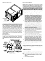
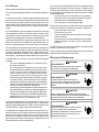
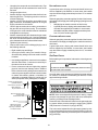
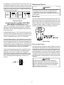
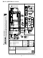
115 VOLT LINE CONNECTION OF ACCESSORIES
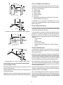
24 VAC HUMIDIFIER
ELECTRONIC AIR CLEANER
Optional
Accessories
EAC
Transformer
Line
Line
Transformer
EAC-H
The yellow wire connected to the I.D. Blower pressure switch
is powered anytime the pressure switch is closed and provides
(GME8, AMEH8, GDH8 & A/GMH8 MODELS ONLY)
24 VAC humidifier control. Remove the yellow wire and connect a field supplied jumper wire with a “piggyback” terminal to
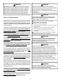
WARNING
the pressure switch terminal. Reconnect the yellow wire to the
HIGH VOLTAGE !
“piggyback” terminal on the jumper wire and then connect the
24 VAC line of the humidifier to the stripped end of the jumper
TO AVOID PERSONAL INJURY OR DEATH DUE TO wire. Using a wire nut or a field-supplied quick connect terminal
ELECTRICAL SHOCK, DISCONNECT ELECTRICAL POWER can make this connection. The wiring must conform to all local
BEFORE SERVICING OR CHANGING ANY ELECTRICAL and national codes. Connect the COM side of the humidifier to
WIRING.
the B/C terminal on the furnace control board (or to the COM
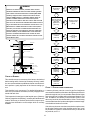
The furnace integrated control module is equipped with line side of the 24 VAC transformer). DO NOT CONNECT 115V
voltage accessory terminals for controlling power to an optional HUMIDIFIER TO THESE TERMINALS.
field-supplied electronic air cleaner.
GAS SUPPLY AND PIPING
The accessory load specifications are as follows:
The furnace rating plate includes the approved furnace gas inElectronic Air Cleaner
1.0 Amp maximum at 120 VAC
put rating and gas types. The furnace must be equipped to
operate on the type of gas applied. This includes any converTurn OFF power to the furnace before installing any accesso- sion kits required for alternate fuels and/or high altitude.
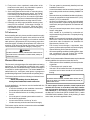
ries. Follow the air cleaner manufacturers’ instructions for loCAUTION
cating, mounting, grounding, and controlling these accessories. Accessory wiring connections are to be made through
TO PREVENT UNRELIABLE OPERATION OR EQUIPMENT DAMAGE, THE the 1/4" quick connect terminals provided on the furnace inteINLET GAS SUPPLY PRESSURE MUST BE AS SPECIFIED ON THE UNIT grated control module. The electronic air cleaner hot terminal
RATING PLATE WITH ALL OTHER HOUSEHOLD GAS FIRED APPLIANCES is identified as EAC-H and the neutral terminal is identified as
OPERATING.
NEUTRAL. All field wiring must conform to applicable codes.
Connections should be made as shown in the following illustraInlet gas supply pressures must be maintained within the ranges
tion.
specified in the following table. The supply pressure must be
constant and available with all other household gas fired appliControl Module
ances operating. The minimum gas supply pressure must be
Neutral
120
VAC
Hot 120 VAC
maintained to prevent unreliable ignition. The maximum must
not be exceeded to prevent unit overfiring.
NOTE: Do not remove the gas valve inlet plug before the gas
line is installed. replace if water or debris has been introduced.
Air Cleaner
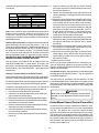
INLET GAS SUPPLY PRESSURE
GME8, AMEH8, GDH8 & A/GMH8 MODELS ONLY
If it is necessary for the installer to supply additional line voltage wiring to the inside of the furnace, the wiring must conform
to all local codes, and have a minimum temperature rating of
105°C. All line voltage wire splices must be made inside the
furnace junction box.
Natural Gas
Minimum: 4.5" w.c.
Maximum: 10.0" w.c.
Propane Gas
Minimum: 11.0" w.c.
Maximum: 13.0" w.c.
NOTE: Adjusting the minimum supply pressure below the limits
in the above table could lead to unreliable ignition. Gas input to
the burners must not exceed the rated input shown on the
rating plate. Overfiring of the furnace can result in premature
heat exchanger failure. Gas pressures in excess of 13 inches
The integrated control module electronic air cleaner terminals water column can also cause permanent damage to the gas
(EAC) are energized with 115 volts whenever the circulator blower valve.
is energized.
At all altitudes, the manifold pressure must be within 0.3 inches
w.c. of that listed in the Specification Sheet applicable to your
model for the fuel used. At all altitudes and with either fuel, the
air temperature rise must be within the range listed on the furnace nameplate. Should this appliance be converted to LP,
refer to the instructions included in the factory authorized LP
conversion kit.
19