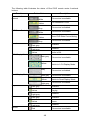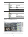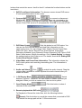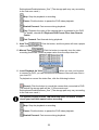
1
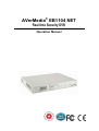
AVerMedia® EB1104 NET
Real-time Security DVR
Operation Manual
FCC NOTICE
This device has been tested and found to comply with the limits for a Class A digital device,
pursuant to Part 15 of the FCC Rules. These limits are designed to provide reasonable protection
against harmful interference in a commercial, industrial or business environment. This equipment
can generate, use and radiate radio frequency energy and, if not installed and used in accordance
with the instruction, may cause harmful interference to radio communications. However, there is no
guarantee that interference will not occur in a particular installation. If this equipment does cause
harmful interference to radio or television reception, which can be determined by turning the
equipment off and on, the user is encouraged to try to correct the interference by one or more of the
following measures:
• Reorient or relocate the receiving antenna.
• Increase the separation between the equipment and receiver.
• Connect the equipment into an outlet on a circuit different from that to which the receiver is
connected.
• Consult the dealer or an experienced radio/TV technician for help.
This device complies with Part 15 of the FCC Rules. Operation is subject to the following two
conditions: (1) this device may not cause harmful interference, and (2) this device must accept
any interference received, including interference that may cause undesired operation.
CAUTION ON MODIFICATIONS
To comply with the limits for the Class A digital device, pursuant to Part 15 of the FCC Rules, this
device must be installed in computer equipment certified to comply with the Class A limits. All cables
used to connect the computer and peripherals must be shielded and grounded. Operation with
non-certified computers or non-shielded cables may result in interference to radio or television
reception.
Any changes or modifications not expressly approved by the grantee of this device could void the
user's authority to operate the equipment.
CE NOTICE
This is a Class A product.
DISCLAIMER
No warranty or representation, either expressed or implied, is made with respect to the contents of
this documentation, its quality, performance, merchantability, or fitness for a particular purpose.
Information presented in this documentation has been carefully checked for reliability; however, no
responsibility is assumed for inaccuracies. The information contained in this documentation is
subject to change without notice.
In no event will AVerMedia be liable for direct, indirect, special, incidental, or consequential
damages arising out of the use or inability to use this product or documentation, even if advised of
the possibility of such damages.
TRADEMARKS
AVerMedia is a registered trademark of AVerMedia TECHNOLOGIES, Inc. All other products or
corporate names mentioned in this documentation are for identification and explanation purposes
only, and may be trademarks or registered trademarks of their respective owners.
COPYRIGHT
©
2005 by AVerMedia TECHNOLOGIES, Inc. All rights reserved. No part of this publication may be
reproduced, transmitted, transcribed, stored in a retrieval system, or translated into any language in
any form by any means without the written permission of AVerMedia TECHNOLOGIES, Inc.
VER 01
WARNING
TO REDUCE RISK OF FIRE OR ELECTRIC SHOCK,
DO NOT EXPOSE THIS APPLIANCE TO RAIN OR
MOISTURE.
CAUTION
IF THERE IS ANY DAMAGE, SHORTAGE OR
IMAPPROPRIATE ITEM IN THE PACKAGE, PLEASE
CONTACT WITH YOUR LOCAL DEALER. WARRANTY
VOID FOR ANY UNAUTHORIZED PRODUCT
MODIFICATION.
Table of Contents
Chapter 1 Introduction .......................................................................................... 3
1.1
Features and Specifications ....................................................................... 3
1.2
Package Content........................................................................................ 5
1.3
Front Panel ................................................................................................ 6
1.4
Back Panel................................................................................................. 7
1.5
Setting Up the DVR Unit ............................................................................ 8
1.5.1 Installing Hard Drives............................................................................. 8
1.5.2 Installing a Removable Hard Drive Case in a PC (Optional)................ 13
1.5.3 Connecting Devices............................................................................. 13
1.5.3.1 Basic Devices .................................................................................. 14
1.5.3.2 Optional Devices .............................................................................. 14
Chapter 2 Operating the DVR Unit ..................................................................... 16
2.1
First Time Use .......................................................................................... 16
2.2
Surveillance Screen ................................................................................. 17
2.2.1 Setting the Video Quality...................................................................... 18
2.3
Video Recording and Playback ................................................................ 19
2.3.1 Recording surveillance video............................................................... 19
2.3.2 Playing back the recorded video.......................................................... 20
Chapter 3 Setup Menu......................................................................................... 23
3.1
CAMERA SELECT ................................................................................... 24
3.2
RECORD SELECT................................................................................... 25
3.3
RECORD MODE...................................................................................... 25
3.4
RECORD FRAME RATE.......................................................................... 26
3.5
VIDEO QUALITY...................................................................................... 26
3.6
RECORD SCHEDULE ............................................................................. 26
3.7
SUB MENU .............................................................................................. 28
3.7.1 PASSWORD CHANGE........................................................................ 28
3.7.2 TIME SET ............................................................................................ 29
3.7.3 VGA SETUP ........................................................................................ 29
3.7.4 MOTION SETUP ................................................................................. 30
3.7.5 AUTO RECORD .................................................................................. 31
3.7.6 AUTO SCAN........................................................................................ 32
3.7.7 PASSWORD SETUP ........................................................................... 32
3.7.8 AUDIO RECORD................................................................................. 33
3.7.9 AUDIO MUTE ...................................................................................... 34
3.8
HARD DRIVE SETUP .............................................................................. 35
1
3.8.1 OVERWRITE ENABLED ..................................................................... 35
3.8.2 MASTER HDD SIZE and MASTER HDD USED ................................. 35
3.8.3 MASTER HDD FORMAT ..................................................................... 35
3.8.4 SLAVE HDD SIZE and SLAVE HDD USED......................................... 35
3.8.5 SLAVE HDD FORMAT......................................................................... 35
3.9
SENSOR SETUP ..................................................................................... 36
3.9.1 SENSOR RECORD TIME ................................................................... 36
3.9.2 ALARM OUT TIME .............................................................................. 36
3.9.3 CHANNEL-1 ~ CHANNEL-4 ................................................................ 36
3.10 LANGEUAGE SETUP.............................................................................. 37
3.11 NETWORK SETUP.................................................................................. 37
3.11.1 ACCEPT CLIENT ............................................................................... 37
3.11.2 MAC ADDRESS ................................................................................. 37
3.11.3 IP ADDRESS ....................................................................................... 37
3.11.4 SUBMASK ........................................................................................... 38
3.11.5 GATEWAY ........................................................................................... 38
Chapter 4 Connect to a PC ................................................................................. 39
4.1
First Time Use .......................................................................................... 39
4.2
Operating EB-DVR Playback Application ................................................. 41
4.2.1 Channel Selection ............................................................................... 43
4.2.2 Video Playback List ............................................................................. 43
4.2.3 Snapshot ............................................................................................. 45
4.2.4 Print ..................................................................................................... 45
4.2.5 Save as AVI Files................................................................................. 45
4.3
Real-Time Monitoring from a Remote Computer...................................... 45
4.3.1 Status of Functional Buttons and Icons .................................................. 47
4.4
Using the 4-CH Remote Center ............................................................... 50
4.5
Using Dual DVR Remote Center.............................................................. 53
4.5.1 Setting DVR Control from Remote Center ........................................... 60
4.5.2 Playback DVR Events Files from Remote Center ................................ 61
4.5.3 Local Recording ................................................................................... 62
4.5.4 Local Playback Recording Files ........................................................... 63
4.5.5 Full Screen Display .............................................................................. 63
Warranty Notice ................................................................................................... 65
2
Chapter 1 Introduction
EB1104 NET is a 4-channel video and 1-channel audio stand-alone network DVR
unit that provides real-time monitoring and digital recording of surveillance video.
Up to four video cameras and four sensor devices can be hooked up to this DVR
unit. It is also equipped with an output relay that allows connection of an alarm
device. The DVR system provides remote real-time monitoring that facilitates a
remote user to monitor the screens anytime as long as Internet is available.
Surveillance, digital recording and playback are controlled through the front panel
buttons. Users can connect EB1104 NET to a PC to trace back video files, and
even save image as both BMP and AVI files. With the On-Screen-Display (OSD)
menu, you can customize video recording settings, sensor and alarm settings,
password protection, hard drive recycling, and more.
Surveillance video is recorded in high-quality Motion-JPEG format. Two recording
modes, Each Mode and Quad Mode, are supported. EACH Mode can record video
from each video camera in 640 x 480 resolution at 7.5 fps. QUAD Mode can record
video in 640 x 480 resolution and up to 30 fps/25 fps (NTSC/PAL).
Connecting cameras, sensors, microphone, speaker, alarm, and display device
1.1 Features and Specifications
• Non-PC stand-alone security network digital video recorder
• 4 composite video inputs and 1 composite output
3
• 1 audio input and 1 audio output
• VGA output for LCD monitor display
• Front panel buttons and OSD control
• Motion-JPEG video compression
• Default factory setting to NTSC or PAL
• Supports 2 hard drives (not included)
• Full-screen resolution:
Display: 720 x 480 (NTSC), 720 x 576 (PAL)
Recording: 640 x 224 (NTSC), 640 x 272 (PAL)
• Display and recording frame rate:
Quad mode: 30/25 fps (NTSC/PAL) per channel, total of 120/100 fps
(NTSC/PAL)
• Scheduled recording (00:00~23:00 set by hour )
• Search for recorded videos by date/time/event
• Input/Output: 4 sensor inputs and 1 relay output control
• Motion detection recording.
• Removable hard disk bay
• 1 USB 2.0 Port
• Software CD with USB playback application for Windows 2000/XP
• Real-time remote monitoring the cameras
• Remote control multiple DVR servers through browser
• Remote preview DVR cameras through browser
• Flexible recording data storage path: Data can be saved on both server side and
client side
• Adjustable audio volume via browser
• Multiple language operation screens
4
1.2 Package Content
AVerMedia® EB1104NET Unit
2
Remote Control & Batteries (Optional)
3
Power Cord (*The power cord may vary according to the local electricity
system.)
4
Power Adaptor
5
DVR accessories (including 4 screws and 1 Ω hook)
6
Quick Install Guide
7
USB Cable
8
Software CD (Manual is included)
9
Removable hard disk drawer accessories (with spare screws)
1
If there is any damage, shortage or inappropriate item in the
package contents, please contact with your local dealer.
5
1.3 Front Panel
1.
REC : Start video recording.
2.
3.
4.
MENU : Open/Close the OSD main menu or subsequent submenus.
: Go up one item.
: Go down one item.
5.
SELECT :
(a) Cycle through various options in a selected menu item.
(b) Open a submenu
6.
:
(a) Display Channel 1 in full-screen.
(b) Pressing this button is equivalent to entering the number "1" when in the
OSD menu.
7.
:
(a) Display Channel 2 in full-screen.
(b) Pressing this button is equivalent to entering the number "2" when in the
OSD menu.
8.
:
(a) Display Channel 3 in full-screen.
(b) Pressing this button is equivalent to entering the number "3" when in the
OSD menu.
9.
:
(a) Display Channel 4 in full-screen.
(b) Pressing this button is equivalent to entering the number "4" when in the
OSD menu.
10.
:
Display cameras in quad screen.
11. ►:
(a) Display the Playlist.
(b) Play back a recording.
12. : Pause playback/recording.
13. ▓: Stop playback/recording
14. : Fast reverse during playback.
15. :
(a) Fast forward during playback.
(b) Switch between the play list and the date/time search controls.
16. Removable hard disk rack with lock
6
CAUTION
BEFORE REMOVING THE REMOVABLE OR INTERNAL HARD DISK,
POWER OFF THE DVR UNIT FIRST.
17.
18.
19.
20.
21.
Removable Hard disk LED
Removable Power LED
Internal Hard Disk LED
DVR Power LED
USB2.0 Socket
1.4 Back Panel
1
LAN Socket: Connect a PC and DVR with a RJ-45 cable to allow remote
real-time surveillance for both intranet and Internet.
2
Audio IN Slot: Input audio signals from an assigned device.
3
Audio OUT Slot: Connect to a speaker to output the audio.
4
VGA OUT (15-pin D-Sub): VGA output for connection to a VGA monitor.
5
VIDEO OUT(BNC): Composite video output for connection to a television
monitor.
6
CH1 ~ CH4(BNC) : Composite video input for connection of up to four video
cameras. (Video input : V = 1 Vp-p)
7
Sensor Inputs and Relay Output: For connection of up to 4 sensor devices
and 1 alarm device. (Relay : 1A @ 125V AC/30V DC)
8
NTSC/PAL Switch: Switch to your local video system.
9
Power Socket: For connecting the power adapter. (12V @ 4.2A)
10 Ω Hook: Fix the power adapter after it is plugged into Power Socket.
7
1.5 Setting Up the DVR Unit
1.5.1 Installing Hard Drives
The DVR unit allows you to install up to two hard drives (a master and slave drive).
Before you install hard drives, please decide the priorities of your hard disks. Adjust
the jumpers’ settings according to the instructions on your hard disk label before
you fix the hard disks.
The minimum hard disks capacity should be 40GB/ 7200RPM.
Hard disks of the same brand are recommended when you install the
hard disks in the DVR. A hard disk compatibility issue may occur due
to different hard disk models.
For more information of the recommended hard disk list, please go to
http://www.avermedia.com/nvd/hardware-recom.htm
8
Follow the steps to install hard disks inside DVR. The DVR provides a flexible
choice to fix either the master hard disk or the slave hard disk inside the DVR.
1. Loosen screws.
2. Remote the upper cover backward and
lift the cover.
3. Loosen 4 screws on the hard disk rack.
4. Tighten screws at sides of the hard disk.
9
5. Connect the gray IDE cable connector to
the hard disk IDE slot, and then connect
the power connect to the hard disk
power slot.
6. Tighten the 4 screws to fix the hard disk.
7. Tighten the screws.
8. Unlock the removable hard disk drawer
before you pull out the removable
drawer.
9. To install a hard disk in the removable
hard disk drawer,remove the removable
hard drive drawer from the case.
10
10. Remove the upper cover of the drawer
and take the hard disk accessories
package out.
11. Connect the power connector to the hard
drive as the right picture shows.
12. Connect the hard disk connector into the
inner tray’s slot.
13. Close the upper cover of the drawer.
Slide the drawer into the removable hard
drive case, and lock the drawer.
14. Lock the drawer before you start to use
EB1104 NET DVR system.
15. Power on the unit to see the LED indicators on the front side of the removable
hard disk holder. If the LED indicators light up, you may use the hard disk.
11
In the situation you want to remove the hard disk from the removable hard
disk drawer, power off the DVR. Unlock the removable hard disk drawer
first.
The following chapters will describe the hard disk in a removable hard disk
drawer as HDD A and the other hard disk inside DVR unit as HDD B to
differentiate the hard disks in the following content.
HDD A
HD D B
12
1.5.2 Installing a Removable Hard Drive Case in a PC (Optional)
For users who purchase an optional hard drive case, please follow the steps to
install the case in a PC.
1.
Power off your PC and remove the cover of your PC.
2.
Remove a front cover and free a 5 1/4” drive bay. Insert the hard disk holder.
Mount the hard disk holder, screw up the holder, and connect the IDE slot and
power connector from PC’s motherboard.
3.
Remove the drawer of the removable hard disk case. Please refer to 1.5.1
Installing Hard Drives to install the hard drive.
4.
Slide the drawer into the removable hard disk case, power on the PC and
check the LED indicators. If the LED indicators light up, it is ok to use the hard
drive in the removable case.
1.5.3 Connecting Devices
At the back panel of the DVR unit, you can connect up to 4 video cameras, 4
sensor devices, 1 audio input and 1 alarm device. Please follow the illustration to
connect devices. To listen to a real-time audio channel, you can connect 1 PC
speaker to DVR. Use a USB cable to connect to a PC if it is necessary.
13
1.5.3.1 Basic Devices
• Cameras
Connect the video output of each video camera or composite video source to
the CH1 ~ CH4 connectors.
• VGA monitor
Connect a VGA monitor to the VGA OUT connector of the DVR unit to use as a
display for video surveillance and playback.
• Power adapter
Plug the provided 110V AC or 220V power adapter into the DVR unit's power
socket.
• Microphone and speaker
Plug a microphone in DVR unit’s audio input socket. Connect a speaker with
amplifier to the audio output socket to play the audio for real-time surveillance.
An AV-jack may be necessary depending on the speaker.
To avoid echoes, please turn off the speaker when DVR is recording. Keep it
away from microphones to avoid unnecessary echoes and interruptions when
DVR is recording.
• Internet devices
Plug a RJ-45 connector into the LAN socket for intranet or Internet.
1.5.3.2 Optional Devices
• Television monitor
Use a BNC-to-RCA adapter to connect a regular TV monitor to the DVR unit's
VIDEO OUT connector.
• Sensors and alarm device
14
Connect up to four sensor devices to the terminals that are numbered 1 to 8 at
the back panel. Each pair of terminals is for the ground (-) and positive (+) input
voltage. For instance:
Terminal 1 : Connect to the ground (-) wire of Sensor 1
Terminal 2 : Connect to the positive (+) wire of Sensor 1
....
....
Terminal 7 : Connect to the ground (-) wire of Sensor 4
Terminal 8 : Connect to the positive (+) wire of Sensor 4
Connect an alarm device to the terminals that are numbered 9 and 10:
Terminal 9 : Connect to the positive (+) wire of the alarm device
Terminal 10 : Connect to the ground (-) wire of the alarm device
• Desktop/Laptop computer
Connect EB1104 NET DVR and PC with the USB cable in the package before
you execute the playback application.
15
Chapter 2 Operating the DVR Unit
2.1 First Time Use
Connecting the DVR unit to a power outlet automatically turns on its power. When
you install new hard disks in your DVR, the system will detect hard disks status and
show “HDD FORMAT SELECT(YES) /MENU(NO)”. Press
to format hard
disks.
V2-0-04
HDD Checking …
MASTER
123593 MB
SLAVE
123593 MB
HDD FORMAT
(SELECT) YES/(MENU) NO
The system will show “ARE YOU SURE PLAY(FORMAT)/STOP(NOT FORMAT)” to
confirm again. Press ► to format hard disks and you will see “HDD FORMATTING”
on the DVR screen.
V2-0-04
HDD Checking …
MASTER
123593 MB
SLAVE
123593 MB
HDD FORMAT
(SELECT) YES/(MENU) NO
ARE YOU SURE
(PLAY) FORMAT/(STOP) NOT FORMAT
When the DVR screen shows “NEW HDD Format completed”, the formatting is
completed.
V2-0-04
HDD Checking …
MASTER
123593 MB
SLAVE
123593 MB
HDD FORMATTING
NEW HDD Format completed
16
Sometimes the system has trouble detecting the hard disks, it
shows “Turn off and on the DVR” on the screen.
Turn off and on the DVR
Follow the instruction to unplug DVR. Reboot and the system will
show the normal first time use screen.
After you format the hard drive(s), please enter the default password before you
enter the main menu. The factory default password is "111111". Use the following
front panel buttons to input a numeric password:
For "1"
For "2"
For "3"
For "4"
You can go to SUBMENU to change the password, and enable the
PASSWORD SETUP function. The default PASSWORD SETUP
setting is NO.
2.2
Surveillance Screen
Surveillance video can be viewed and recorded in two screen modes: EACH mode
and QUAD mode.
Under the EACH mode, video from the video cameras is recorded in full-screen
resolution, but each video takes turns in being recorded (from one camera to the
next). Each of the surveillance videos is recorded only at a maximum frame rate of
7.5fps. When viewing live video using EACH mode, you can switch between full
screen and quad screen.
Whereas in QUAD mode, video from the video cameras is recorded at a lower
resolution, yet each video is recorded in full frame rate, full motion. Videos recorded
17
in QUAD mode can only be played back in QUAD mode.
EACH mode
QUAD mode
Use the following front panel buttons to select the desired video camera to display
in full screen:
CH1: Camera 1
CH2: Camera 2
CH3: Camera 3
CH4: Camera 4
Note: The recording mode can be selected in the OSD main menu.
2.2.1
Setting the Video Quality
Whether you are under Each Mode or Quad Mode, you can modify the video
quality and adjust the video image to a better quality according to the real situation.
When you are in Each Mode, select a camera. Press
to see a video quality
setting screen. You can modify HUE, Saturation, Contrast, and Brightness for this
assigned camera. The default value for each video quality item is 5. Press or 18
to move the cursor to the video quality item you want to change and click
change the value. Repeat the same steps until you finish all settings.
Click
to
to exit the setting screen.
When you are under the Quad Mode, you can change the video value setting for all
cameras at the same time. The system provides a 9-level video quality setting
to see a video quality setting screen. You can modify Hue,
value. Press
Saturation, Contrast, and Brightness for all cameras. The default value for each
video quality item is 5. Press or to move the cursor to the video quality item
you want to change and click
to change the value. Repeat the same steps
until you finish all settings. After you finish the setting, all the cameras will adopt the
same video quality settings.
Click
to exit the setting screen.
2.3 Video Recording and Playback
When you are back to the preview mode, the system will start to record the video
automatically when it detects a 10-second idleness. The default setting for auto
record is on. When “PASSWORD SETUP” is enabled, you need to enter the
password after clicking the STOP button. Please enter your password. The system
stops recording when the authentication is confirmed.
2.3.1 Recording surveillance video
1
To customize recording settings, press
and choose the desired recording
settings. Refer to the section, "Setup Menu" for details.
19
2
Press the
button. During recording, the screen shows the following:
R1
2R
R3
4R
8
1
2
EACH
REC
(S)
(T) 2005 /04 /18 17 : 20 : 25
MASTER
18%
3
7
6
5
4
Here is a simple description of the screen item.
Screen Items
Description
1
Recording status
2
Display mode
3
Recording hard disk.
“M” means Master, and “S” means Slave.
4
Recording mode
5
Recording hard disk.
6
Percentage of the used hard disk space
7
Recording time
8
“4R” means “Channel 4 is recording”.
3
To stop the recording, press ▓.
2.3.2 Playing back the recorded video
1
Press X to display the Playlist:
20
2
If you want to switch to the other hard drive or search for a range of video
recordings, press . The ">" arrowhead cursor will then move up to the top of
the screen.
3
Press
4
Press to move down to the recording date and time entries.
5
Press or to move through each item in the recording date and time entries.
While on an item such as the month, press
button repeatedly to cycle
through the numbers, and stop pressing the button when you have reached the
desired number.
6
Press to move the cursor back to the Playlist.
7
Press or to move up or down in the Playlist.
8
When you have selected the desired video recording, press X to play back.
button to switch between the MASTER and SLAVE drives.
21
9
To fast forward through the video, press . To fast reverse, press .
10 Press to pause playback, or press ▓ to stop playback.
22
Chapter 3 Setup Menu
MAIN MENU
> CAMERA SELECT
RECORD SELECT
RECORD MODE
RECORD FRAMERATE
VIDEO QUALITY
RECORD SCHEDULE
SUBMENU
HARD DRIVE SETUP
SENSOR SETUP
LANGUAGE SETUP
NETWORK SETUP
1234
1234
EACH
30
NORMAL
RECORD SCHEDULE
v
+TTTSSSSSTTTTMMMMTTTTT+
|
|
|
|
|
|
|
|
|
0
3
6
9
12 15 18 21 24
PRESS (< , >), THEN(SELECT)
PRESS (MENU) TO EXIT
EN
PRESS (< , >), THEN(SELECT)
PRESS (MENU) TO EXIT
SUB MENU
> PASSWORD CHANGE
TIME SET
VGA SETUP
MOTION SETUP
AUTO RECORD
AUTO SCAN
PASSWORD SETUP
AUDIO RECORD
AUDIO MUTE
TIME
CURRENT PASSWORD:
NEW
ON
OFF
NO
OFF
OFF
VGA SETUP
2004/01/10 15:30:25
^
> RESOLUTION
1024 ^ 768
REFRESH RATE
60HZ
PRESS (<, >),THEN(SELECT)
PRESS (MENU) TO EXIT
PRESS (< , >), THEN(SELECT)
PRESS (MENU) TO EXIT
MOTION SETUP
MOTION CAMERA
____
MOTION SENSITIVITY
05
MOTION RECORD TIME 05
PASSWORD:
CONFIRM PASSWORD:
HARD DRIVE SETUP
> OVERWRITE ENABLED
YES
MASTER HDD SIZE
80072MB
MASTER HDD USED
16014MB 20%
MASTER HDD FORMAT
SLAVE HDD SIZE
N/A
SLAVE HDD USED
N/A
SLAVE HDD FORMAT
PRESS (< , >), THEN(SELECT)
PRESS (MENU) TO EXIT
SENSOR SETUP
> SENSOR RECORD TIME
ALARM OUT TIME
CHANNEL-1
CHANNEL-2
CHANNEL-3
CHANNEL-4
15
05
TYPE:NORMAL-CLOSE
TYPE:NORMAL-OPEN
NOT INSTALLED
NOT INSTALLED
PRESS (< , >), THEN(SELECT)
PRESS (MENU) TO EXIT
> English
Japanese
French
Spanish
Polish
NETWORK MENU
> ACCEPT CLIENT
MAC ADDRESS
IP ADDRESS
SUBNET MASK
GATEWAY
FF:FF:FF:FF:FF:FF
61.62.184.32
255.255.255.000
61.62.184.254
PRESS (< , >), THEN(SELECT)
PRESS (MENU) TO EXIT
23
PRESS (< , >), THEN(SELECT)
PRESS (MENU) TO EXIT
1 Press
button to display the OSD main menu.
MAIN MENU
> CAMERA SELECT
RECORD SELECT
RECORD MODE
RECORD FRAMERATE
VIDEO QUALITY
RECORD SCHEDULE
SUBMENU
HARD DRIVE SETUP
SENSOR SETUP
LANGUAGE SETUP
NETWORK SETUP
1234
1234
EACH
30
NORMAL
EN
PRESS (< , >), THEN(SELECT)
PRESS (MENU) TO EXIT
2 Press or to move up or down through the items in the menu. The ">"
arrowhead cursor moves as you press these buttons.
3 The first five items in the menu provide selectable settings. Press
to
repeatedly cycle through the available settings. Stop pressing the button when
you have chosen the desired setting.
4 The last four items in the menu are second-level menus. Press
the corresponding menu.
5 When you are in a second-level menu, press
to display
to return to the main menu.
6 To close the main menu and return to the surveillance screen, press
again.
When you are back to the preview mode, the system will start to
record the video automatically when it detects a 10-second
idleness. If you already adjust the PASSWORD SETUP to YES,
please enter the password to interrupt the recording before clicking
the STOP button. The system stops recording when the
authentication is confirmed.
3.1 CAMERA SELECT
This determines which of the cameras will be displayed on the surveillance screen.
Use the following front panel buttons to individually switch on or off each of the
camera displays:
24
CH1: Camera 1
You can also press
For instance:
CH2: Camera 2
CH3: Camera 3
CH4: Camera 4
to cycle through different camera display combinations.
(1 2 3 4) : Switch on all camera displays.
(1 - - 4) : Switch on camera display 1 and 4 only.
(- 2 3 -) : Switch on camera display 2 and 3 only.
(- - - -) : Disable all camera displays.
3.2 RECORD SELECT
This determines which of the cameras surveillance video will be recorded from. The
way to select cameras is the same as CAMERA SELECT.
Note: Only the enabled camera displays in the CAMERA SELECT item can be
selected for recording.
3.3 RECORD MODE
There are two recording modes to choose from: EACH and QUAD.
When you choose the EACH recording mode, you can view each camera display in
full-screen during the recording process by using the following front panel buttons:
CH1: Camera 1
CH2: Camera 2
CH3: Camera 3
CH4: Camera 4
Likewise, when you finish recording, you can also play back the recorded video in
full-screen by using the above buttons.
While you are viewing or recording video in full screen, press
display back to quad screen.
to switch the
Note: Refer to the section "2.2 Surveillance Screen" for details on the differences
between EACH and QUAD modes.
25
3.4 RECORD FRAME RATE
This sets the number of images per second of video that is recorded. There are 6
record frame rates for selection for NTSC video system, including 30,15,10,7,5 and
4. For PAL video system, the system provides 5 recording frame rates, including
25,12,8,6,and 4.When you select a larger frame rate, the recording file size will be
larger.
By default, frame rate is set at 30 fps for NTSC, 25 fps for PAL.
3.5 VIDEO QUALITY
There are three video quality settings to choose from: BEST, GOOD or NORMAL.
Choosing NORMAL allows you to record more on hard drive, but the quality of
recorded video images is moderate.
Recording hours on 120GB hard drive are approximately as follows:
Video
Signal
Display
Format
QUAD
mode
NTSC
EACH
mode
Video
Signal
Display
Format
QUAD
mode
PAL
EACH
mode
Video
Quality
30 fps
15 fps
7 fps
4 fps
BEST
41 hrs
83 hrs
178 hrs
312 hrs
GOOD
53 hrs
106hrs
227hrs
397hrs
NORMAL
65hrs
129hrs
277hrs
485hrs
BEST
71 hrs
141hrs
302hrs
529hrs
GOOD
93 hrs
186 hrs
399 hrs
698 hrs
NORMAL
116hrs
233hrs
499hrs
873hrs
Video
Quality
25fps
12 fps
6 fps
4 fps
BEST
44 hrs
87hrs
187hrs
280hrs
GOOD
55 hrs
110hrs
236hrs
354hrs
NORMAL
67hrs
134hrs
286hrs
429hrs
BEST
71 hrs
143hrs
305hrs
458hrs
GOOD
94hrs
188hrs
402hrs
603hrs
NORMAL
125hrs
251hrs
536hrs
804hrs
*The data size may vary depending on the complexity of video scenes.
* For more information about the recording time, please visit:
http://www.avermedia.com/nvd/recording%20hour(EN0903).htm
3.6 RECORD SCHEDULE
By default, the DVR unit is customized for continuous 24-hour video recording. If
26
you prefer to record video only at certain time schedules within a day, you can
choose specific recording hours. If the DVR unit is connected to sensor devices,
you can also customize the unit to initiate video recording only when the sensors
detect an event.
RECORD SCHEDULE
v
+TTTTTTTTTTTTTTTTTTTTTTT+
|
|
|
|
|
|
|
|
|
0
3
6
9
12 15 18 21 24
PRESS (< , >), THEN(SELECT)
PRESS (MENU) TO EXIT
To customize the recording schedule:
1 Each number in the RECORD SCHEDULE menu represents the time schedule
(in hours) for recording, and the "v" cursor indicates the time that is selected.
Press or to move through the time schedules.
2 Press
repeatedly to cycle through these settings:
( T ) For automatic non-stop video recording
( S ) For sensor recording. The DVR unit initiates recording only when
the attached sensor devices detect motion from the video cameras.
( M ) For motion recording. The DVR unit initiates recording only when
motion is detected from video cameras.
( - ) Disables recording at that time schedule.
27
3.7 SUB MENU
The SUB MENU allows you to enable password setup, change the password,
system date and time, VGA display settings, motion setup, auto record setup, auto
scan setup, audio record and mute setting.
SUB MENU
> PASSWORD CHANGE
TIME SET
VGA SETUP
MOTION SETUP
AUTO RECORD
AUTO SCAN
PASSWORD SETUP
AUDIO RECORD
AUDIO MUTE
ON
OFF
NO
OFF
OFF
PRESS (< , >), THEN(SELECT)
PRESS (MENU) TO EXIT
3.7.1 PASSWORD CHANGE
To change the password:
1.
Input the prompted information:
CURRENT PASSWORD :
------
NEW
PASSWORD :
------
CONFIRM PASSWORD :
------
The factory default password is "111111". Use the following front panel
buttons to input a numeric password:
For "1"
2.
For "2"
For "3"
For "4"
The "Password changed" message is then displayed. This message flashes
three times, and then you will be returned to the SUB MENU.
28
Note: You will be prompted to enter the password when you attempt to format
the hard drive(s) in the HARD DRIVE SETUP menu.
3.7.2 TIME SET
TIME
2004/01/10 15:30:25
^
PRESS (< , >), THEN(SELECT)
PRESS (MENU) TO EXIT
To change the system date and time:
1.
Press or to move through the "YYYY/MM/DD" and "HH:MM:SS "
entries. The "^" cursor indicates the entry that is selected.
2.
Per selected entry, press
repeatedly to cycle through the numbers.
Stop pressing the button when you reach the desired number.
3.7.3 VGA SETUP
VGA SETUP
> RESOLUTION
REFRESH RATE
1024 ^ 768
60HZ
PRESS (< , >), THEN(SELECT)
PRESS (MENU) TO EXIT
Set RESOLUTION and REFRESH RATE based on the supported display
mode and refresh rate of the VGA monitor that is connected to the DVR unit.
Different monitors support different refresh rates:
Resolution
640 x 480
800 x 600
1024 x 768
1280 x 1024
Refresh Rate Frequency (Hz)
60, 72, 75, 85
60, 72, 75, 85
60, 70, 75, 85
60
Note: The best refresh rate for LCD monitor is 60Hz.
29
3.7.4 MOTION SETUP
MOTION SETUP
>MOTION CAMERA
MOTION SENSITIVITY
MOTION RECORD TIME
____
01
05
PRESS (< , >), THEN(SELECT)
PRESS (MENU) TO EXIT
To change MOTION CAMERA,
1. Press or to move the arrowhead cursor to MOTION CAMERA in the
menu.
2. Press the channel buttons to select cameras that you want to setup.
To setup all cameras, press
. You will see the screen shows
MOTION CAMERA 1 2 3 4. Press the same button again to cancel the
setting.
To setup channel 1 and 4 only, press
. You will see the screen
shows MOTION CAMERA 1--4.Press the same buttons again to cancel
the setting.
. You will see the screen
To setup channel 2 and 3 only, press
shows MOTION CAMERA -2 3-. Press the same buttons again to cancel
the setting.
To adjust MOTION SENSIVITY,
1.
Press or to move the arrowhead cursor to MOTION SENSITIVITY
in the menu.
2.
Press
repeatedly to cycle through the numbers. The sensitivity
level ranges from 1 to 10. Level 10 is the least sensitive one and Level 1
is the most sensitive one.
To setup the MOTION RECORD TIME,
1.
Press or to move the arrowhead cursor to MOTION RECORD
30
TIME in the menu.
2.
Press
repeatedly to cycle through the numbers. The time setting
ranges from 5 to 30 seconds. Stop pressing the button when reach the
desired numbers.
3.7.5 AUTO RECORD
SUB MENU
PASSWORD CHANGE
TIME SET
VGA SETUP
MOTION SETUP
> AUTO RECORD
AUTO SCAN
PASSWORD SETUP
AUDIO RECORD
AUDIO MUTE
ON
OFF
NO
OFF
OFF
PRESS (< , >), THEN(SELECT)
PRESS (MENU) TO EXIT
AUTO RECORD keeps recording automatically after configuration events by
users or an unpredictable electricity break. When you are back to the
preview mode, the system will start to record the video automatically when it
detects a 10-second idleness. When the hard disk space is running out, the
system will recycle the hard disk space and delete the earliest recordings.
The default HDD overwrite is enabled.
To setup the AUTO RECORD,
1.
Press or to move the arrowhead cursor to AUTO RECORD in the
menu.
2.
Press
to switch to ON or OFF according to your demand. Click
to exit this menu.
31
3.7.6 AUTO SCAN
SUB MENU
PASSWORD CHANGE
TIME SET
VGA SETUP
MOTION SETUP
AUTO RECORD
> AUTO SCAN
PASSWORD SETUP
AUDIO RECORD
AUDIO MUTE
ON
OFF
NO
OFF
OFF
PRESS (< , >), THEN(SELECT)
PRESS (MENU) TO EXIT
AUTO SCAN cycles the videos of each camera when the system is in EACH
MODE.
To setup the AUTO SCAN,
1.
Press or to move the arrowhead cursor to AUTO SCAN in the
menu.
2.
Press
to switch to ON or OFF according to your demand. Click
to exit this menu.
3.7.7 PASSWORD SETUP
SUB MENU
PASSWORD CHANGE
TIME SET
VGA SETUP
MOTION SETUP
AUTO RECORD
AUTO SCAN
> PASSWORD SETUP
AUDIO RECORD
AUDIO MUTE
ON
OFF
NO
OFF
OFF
PRESS (< , >), THEN(SELECT)
PRESS (MENU) TO EXIT
You can change the PASSWORD SETUP setting under the SUB MENU to
enable PASSWORD SETUP. PASSWORD SETUP function protects your
32
system from someone who intends to interrupt the recording or change the
settings.
The default setting for the PASSWORD SETUP is NO. Please move the
arrow cursor to PASSWORD SETUP and press
to adjust the setting to
YES, and press
to return to MAIN MENU. After the function is enabled,
the system will request for the password before you enter MAIN MENU or
stop the recording. After the password confirmation, you are able to stop the
recording or enter the MAIN MENU to change the setting.
3.7.8 AUDIO RECORD
SUB MENU
PASSWORD CHANGE
TIME SET
VGA SETUP
MOTION SETUP
AUTO RECORD
AUTO SCAN
PASSWORD SETUP
> AUDIO RECORD
AUDIO MUTE
ON
OFF
NO
OFF
OFF
PRESS (< , >), THEN(SELECT)
PRESS (MENU) TO EXIT
The system supports audio recording for ONE channel.
To setup the AUDIO RECORD,
1.
Press or to move the arrowhead cursor to AUDIO RECORD in the
menu.
2.
Press
to switch to ON or OFF according to your demand. Click
to exit this menu.
33
3.7.9 AUDIO MUTE
SUB MENU
PASSWORD CHANGE
TIME SET
VGA SETUP
MOTION SETUP
AUTO RECORD
AUTO SCAN
PASSWORD SETUP
AUDIO RECORD
> AUDIO MUTE
ON
OFF
NO
OFF
OFF
PRESS (< , >), THEN(SELECT)
PRESS (MENU) TO EXIT
When the DVR is connected to the speaker, it will transmit the audio of a
microphone. When DVR is under preview or record mode, you can either
turn on the AUDIO MUTE or turn off the speaker if you don’t want to listen to
the audio. Otherwise, you may listen to the audio if you turn off the AUDIO
MUTE.
To setup the AUDIO MUTE,
1.
Press or to move the arrowhead cursor to AUTO MUTE in the
menu.
2.
Press
to switch to ON or OFF according to your demand. Click
to exit this menu.
34
3.8 HARD DRIVE SETUP
HARD DRIVE SETUP
> OVERWRITE ENABLED
YES
MASTER HDD SIZE
80072MB
MASTER HDD USED
16014MB 20%
MASTER HDD FORMAT
SLAVE HDD SIZE
N/A
SLAVE HDD USED
N/A
SLAVE HDD FORMAT
PRESS (< , >), THEN(SELECT)
PRESS (MENU) TO EXIT
3.8.1
OVERWRITE ENABLED
This allows old video recordings on the hard drive(s) to be automatically
overwritten with new recordings when hard drive space is full.
Press
3.8.2
to enable or disable this feature (i.e., choose YES or NO).
MASTER HDD SIZE and MASTER HDD USED
These items show the MASTER hard drive capacity and the amount of disk
space that has been used up by the video recordings.
3.8.3
MASTER HDD FORMAT
Press
on this menu item to reformat the MASTER hard drive. You will
then be prompted to enter the password. If an invalid password is entered,
you will not be allowed to format the hard drive.
Note: All recordings on the MASTER hard drive will be deleted when you
reformat the hard drive.
3.8.4
SLAVE HDD SIZE and SLAVE HDD USED
These items show the SLAVE hard drive capacity and the amount of disk
space that has been used up by the video recordings.
3.8.5
SLAVE HDD FORMAT
on this menu item to reformat the SLAVE hard drive. You will
Press
then be prompted to enter the password. If an invalid password is entered,
you will not be allowed to format the hard drive.
Note: All recordings on the SLAVE hard drive will be deleted when you
reformat the hard drive.
35
3.9 SENSOR SETUP
SENSOR SETUP
> SENSOR RECORD TIME
ALARM OUT TIME
CHANNEL-1
CHANNEL-2
CHANNEL-3
CHANNEL-4
15
05
TYPE:NORMAL-CLOSE
TYPE:NORMAL-OPEN
NOT INSTALLED
NOT INSTALLED
PRESS (< , >), THEN(SELECT)
PRESS (MENU) TO EXIT
3.9.1
SENSOR RECORD TIME
This determines the duration of sensor recording (in minutes) in the event that t
he sensor devices detect an event. There are 6 selections to choose from.
3.9.2
ALARM OUT TIME
This determines the duration of sound (in minutes) that is set off when the
alarm device is triggered.
3.9.3
CHANNEL-1 ~ CHANNEL-4
These correspond to the four sets of sensor inputs on the DVR unit. Customize
these according to the initial state of the attached sensor devices. There are
three states to choose from:
NOT INSTALLED: Indicates that the channel does not have a sensor
device connected.
NORMAL-OPEN: Indicates that the initial state of the sensor device is
Normal-Open. When the sensor device detects an
event and its state changes to Normal-Close, video
recording is initiated.
NORMAL-CLOSE: Indicates that the initial state of the sensor device is
Normal-Close. When the sensor device detects an
event and its state changes to Normal-Open, video
recording is initiated.
36
3.10 LANGEUAGE SETUP
> ENGLISH
JAPANESE
FRENCH
SPANISH
POLISH
Move the cursor to LANGUAGE SETUP and press
on MAIN MENU, you will
see a language list. Select a proper language and click
to return to MAIN
MENU. The language on the screen will turn to your assigned language.
3.11 NETWORK SETUP
Please select Network setting on the main menu. Press
OSD screen.
to see the following
NETWORK MENU
> ACCEPT CLIENT
MAC ADDRES
IP ADDRESS
SUBNET MASK
GATEWAY
(YES)
AB:E2:C1:D3:EE:B5
61.32.11.15
255.255.255.0
61.32.11.10
PRESS (< , >), THEN(SELECT)
PRESS (MENU) TO EXIT
3.11.1
ACCEPT CLIENT
The DVR can accept or refuse an inbound connection from a remote client as
you enable or disable the function, ACCEPT CLIENT.
Move the cursor to ACCEPT CLIENT and press
inbound connections, click
again to change to NO.
3.11.2
for YES. To refuse
MAC ADDRESS
The system will catch a MAC address automatically when you turn on this DVR.
You don’t need to setup MAC address.
3.11.3 IP ADDRESS
Move the cursor to IP ADDRESS and press
37
to enter the IP ADDRESS.
When the system will appear an upper arrow below the digit, click or to
select a proper digit. Press
to return to NETWORK MENU when you
finish entering IP address. Please use a fixed IP when you set up the IP
ADDRESS.
3.11.4 SUBMASK
Move the cursor to SUBMASK and press
to enter the SUBMASK. When
the system will appear an upper arrow below the digit, click or to select a
proper digit. Press
to return to﹪ NETWORK MENU when you finish
entering SUBMASK.
3.11.5 GATEWAY
to enter the GATEWAY. When
Move the cursor to GATEWAY and press
the system will appear an upper arrow below the digit, click or to select a
proper digit. Press
to return to NETWORK MENU when you finish
entering GATEWAY.
38
Chapter 4 Connect to a PC
EB1104 NET provides a convenient tool to trace back the recorded surveillance
video, catch specific images and save as AVI files. With the Playback Application,
users can play back the surveillance video, catch images and backup all recorded
images easily .
4.1 First Time Use
Connecting DVR unit to a power outlet automatically turns on its power.
If the user needs to save the recording data as AVI files or watch data in
both HDD A and HDD B, please follow the steps to connect your PC and
DVR unit with an USB cable after installing the playback application.
1. Press ▓ to stop recording if DVR is recording.
2. Press
on the DVR front panel to enter MAIN MENU.
3. Connect the USB cable to your PC and DVR unit.
After you finish the play/backup task, please follow the step to unplug the
USB cable:
1. Close the playback application.
2. Unplug the USB cable.
3. Return to Each mode or Quad mode.
39
Follow the instructions to install the driver:
1.
Insert the CD driver into CD-ROM’s
plate. Click Install USB Playback
Application to install the system.
Note: The application supports
Windows 2000/XP only.
2.
You will see the screen on the right
side.
3.
Click Next. Follow the steps to finish
the installation.
4.
Please click Browser.. to change the
directory if it is necessary. Click Next
to continue the installation.
Note: You can see the DVR Playback
Application version on the top of this
screen when you install this
application.
40
5.
Click Finish to complete the
installation.
4.2 Operating EB-DVR Playback Application
Click
to run the application. Select the hard disk and then select a
proper video system according to your local video system. Click OK.
When you install 2 hard disks in the DVR, the master hard disk will be prior to
the slave hard disk. Hence, you will see the master hard disk on the top of the
HDD list.
You will see EB-DVR screen as followed.
41
1.
Time Slider: Drag the slider right or left to fast search an event.
2.
Mute: Click the button to enable audio. When the audio is enabled, the button
turns
.
3.
Volume Slider: Drag the volume slider right to volume up the audio ;drag the
slider left to volume down the audio.
4.
Back One Frame: Display a backward static frame.
5.
Back Play: Play the video backward.
6.
Pause: Pause the playback.
7.
Play: Play the recorded video.
8.
Forward One Frame: Display a forward static frame.
9.
Recording Time: Display recording date and time of the file.
10. Speed Down/Up: Click
or
to speed down/up the playing speed.
The system provides 5 speeds:1X, 2X, 4X,8X and 16X for selection.
11. Each Display Mode: Click
,
,
, or
to show Each Mode
Display. The screen will show only one screen of the assigned camera. You
can switch the cameras between Camera1- Camera4.
12. Quad Display Mode: You can click
to quad screen. The system will
show 4 cameras at the same time. When you click the button, it turns yellow.
13. Change HDD: Switch between different hard disks.
42
14. Event List: Display all the recorded events stored in hard disks.
15. Transform to AVI: Record an appointed video and save it as an AVI file.
16. Print: Print the current display.
17. Snapshot: Save the present screen as a BMP file.
18. Version Identification: Press Ctrl + Alt + V buttons to see the product version
if you need this when you contact with customer service.
4.2.1 Channel Selection
This determines which of the cameras will be displayed on the surveillance
screen.
Choose an appointed channel to display the surveillance screen by clicking the
channel icon. Click once to show a full-screen display. To show a quad screen,
click the same icon again.
4.2.2 Video Playback List
After selecting the appointed hard drive, click
OK to play back the appointed surveillance.
to select an event and click
Click
to pop-up an event table as the following illustration shows. You will
see the table shows Record mode, Start time and End time of each event.
Record Mode can be “T”, “M” or “S”. “T” represents Total Recording, which
means the camera keeps on recording continually. “M” means Motion
Recording, which means the recording starts once the camera detects motion.
“S” represents Sensor Recording, which means the camera records when the
sensor detects an event.
Event List enables you to playback any recorded event anytime.
43
Record Mode
Start Time
End Time
When you decide which event to play, click
to display the video or click
to display a recorded dynamic event reversely. Click
to search the appointed
video. Users can select the forward search mode fast play at 2X, 4X, 8X or 16X
speed. Click once to fast play the video at 2X. Click twice to fast play the video at
4X. Click 3 times to fast play the video at 8X. Click 4 times to fast play the video
at 16X.Click the same button to cycle through different fast play modes. You can
also click
or
to speed up/ slow down the playing speed. The following
picture shows the video is played at a normal speed.
There are 5 play modes: X1, X2, X4, X8 and X16. “X1” means the record is
played at a normal speed.
44
Click
click
Click
to see a forward static play. To see a backward static display,
.
to pause the playing.
4.2.3 Snapshot
Click
to save the desired screen as a BMP file. Users can keep a
full-screen snapshot or a quad screen snapshot. This service allows to keep
static images.
4.2.4 Print
Click
to print the screen. Users can switch to a specific channel and print
out the image during the surveillance. Printing is allowed in a display of
full-screen mode or quad-screen.
4.2.5 Save as AVI Files
Users can backup or catch the data in DVR unit’s hard disks by saving the
recorded video as AVI files and play the files by Windows Media Player.
Click
to save an appointed surveillance video. After clicking the icon, a
window shows to request the file name and directory. Click Save to start the
recording. Click
again to finish the recording.
4.3 Real-Time Monitoring from a Remote Computer
EB1104 enables ONE user to monitor the cameras real-time from a remote PC in
each time, thus the remote administrator can monitor the camera remotely
everywhere as Internet is available. Make sure the DVR uses a fixed network IP
before you connect to the server from a client.
Please follow steps to use the network function.
1. Double click
on your desktop.
2. Enter DVR IP. You need to inquire your local dealer for the server IP and then
enter “/EB1104NET.htm” for 4-CH DVR remote center or “/EB2DVR.htm” for
DUAL DVR remote center after the server IP as the following picture. The
server IP that your local dealer provides may vary. Please refer to your local
45
dealers for server IP.
3. The system will show a security dialog screen, click Yes to continue.
4. Enter your DVR IP and password. Click OK to continue.
5. The remote center screen may vary due to the DVR server quantities. For ONE
DVR server users, you will see a 4-CH screen, as the lower-left picture shows.
For multiple DVR server users, you will see a dual DVR remote center screen,
as the lower-right picture shows.
4-CH remote center screen
Dual remote center screen
Check 4.4 Using the 4-CH DVR Remote Center and 4.5 Using Dual DVR
Remote Center for more information.
46
4.3.1 Status of Functional Buttons and Icons
The following table illustrates the status of 4-CH remote center functional buttons.
Function
Button Color
Connect to the
network
Dark gray
This service is available.
Yellow
The connection is ON
Light gray
This service is disabled.
Dark gray
This service is available.
Yellow
Show DVR State Control dialog
DVR State Control
Sound
Light gray
Dark gray
This service is disabled.
Light gray
Disabled
Yellow
Audio is ON.
1-CH Display Mode
Dark gray
Yellow
Light gray
Quad Display Mode
Play
Pause
Record
Description
Available
This service is available.
Switch to 1-CH Display Mode.
This service is disabled.
Dark gray
This service is available.
Yellow
Switch to Quad Display Mode.
Light gray
This service is disabled.
Dark gray
Available.
Yellow
Playing
Light gray
Disabled.
Dark gray
Available.
Yellow
Pause
Light gray
Disabled
Red
This service is available.
Yellow
Record
47
Rewind Forward
Fast Forward
Stop
Auto Frame Rate
Tune
Manual Frame Rate
Tune
Light gray
Disabled
Dark Gray
Available.
Yellow
Rewind Forward
Light gray
Disabled
Dark Gray
Available.
Yellow
Fast Forward
Light gray
Disabled
Dark Gray
Available.
Yellow
Stop
Light gray
Disabled
Dark Gray
This service is available.
Light Gray
This service is disabled.
Yellow
Auto tune mode
Dark Gray
This service is available.
Light Gray
This service is disabled.
Yellow
Manual tune mode
Monitor
Monitor
Fast Forward
Fast Forward
Rewind Forward
Rewind Forward
Stateless
Stateless
Play
Play
Pause
Pause
48
The following table illustrates the status of Dual DVR remote center functional
buttons.
Function
Button Color
Connect to the
network
White
This service is available.
Yellow
The connection is ON
Gray
This service is disabled.
White
This service is available.
Yellow
Show DVR State Control dialog
Gray
This service is disabled.
DVR State Control
Sound
Dark gray
Available
Light gray
Disabled
Yellow
Audio is ON.
1-CH Display Mode
Dark gray
Yellow
Gray
Quad Display Mode
Play
Pause
Record
Description
This service is available.
Switch to 1-CH Display Mode.
This service is disabled.
Dark gray
This service is available.
Yellow
Switch to Quad Display Mode.
Light gray
This service is disabled.
Dark gray
Available.
Yellow
Playing
Light gray
Disabled.
Dark gray
Available.
Yellow
Pause
Light gray
Disabled
Red
This service is available.
49
Rewind Forward
Fast Forward
Stop
Full Screen
Yellow
Record
Light gray
Disabled
Dark gray
Rewind Forward
Yellow
Pause
Light gray
Disabled
Dark gray
Available.
Yellow
Fast Forward
Light gray
Disabled
Dark gray
Available.
Yellow
Stop
Light gray
Disabled
Gray
This service is available.
Yellow
Click this button to switch to Full
Screen
Light gray
Disabled
4.4 Using the 4-CH Remote Center
When you connect to a 4-CH DVR Remote center, you will see the following
screen.
Here is a brief introduction of each button on the screen. Item1 to Item3 shows the
introduction to “Connection and DVR State”; Item 4 to Item8 explain the function
50
buttons that control the server. Item9 to Item11 indicate the function buttons on the
local client.
1. DVR IP and Speed Information: The browser screen shows DVR server
IP and speed information in the screen.
: Click
to connect or disconnect
2. Connect DVR
EB1104 NET server.The button turns yellow when it is connected to the
network. The system will show the following Client Connection Manager
screen. Enter DVR server’s IP and password. Click OK to connect to DVR.
3. DVR State Control
: Click this button to set DVR status. You
can see the DVR Record Mode and Hard Disk Information on the
upper-right corner. You can change Video Quality, Record Frame Rate,
Alarm Out Time, Sensor Record Time, Audio Record, Audio Mute,
Recording Schedule, Input Channels, Record Channels, DVR Time in DVR
State Control screen. Modify the settings. Click “Update Setting” to change
the settings before click Close to exit. For details, check 4.5.1 Setting DVR
Control from Remote Center.
4. Video Mode and Frame Rate Information: The information shows the
DVR visual system and recording transmitting rate. The information is
read-only.
5. Audio and Volume : Click
to enable the audio channel. Drag the
volume slider up/down to volume up/down the audio channel after you
enable the audio.
: Switch
6. 1-CH Display Mode
between Camera1- Camera4. You can enable or disable cameras you
assigned. When you click a camera icon, the icon turns yellow.
7. Quad Display Mode
cameras at the same time.
: Click this button to show 4
8. Remote playback the DVR video
:
To Playback or Record the video files, click the following buttons.
Record: Click the button to record the camera that connected to DVR.
The default file storage path will be “C:\Documents and
51
Settings\user\Desktop\stream_files” (The storage path may vary according
to the real user name.)
Stop: Stop the playback or recording.
Pause: Click the button to pause the DVR video playback.
Rewind Forward: Fast reverse during playback.
Play: Playback the video of the camera that is connected to the DVR.
For details, check 4.5.2 Playback DVR Events Files from Remote
Center.
Fast Forward: Fast forward during playback.
: Click the button, and the system will tune a proper
9. Auto Tune
video recording frame rate.
10. Manual Tune
: Click the button to manually tune the video
recording frame rate. Select a proper value from the drop-down list.
11. Local Playback the Video
: When you use your browser
to connect to DVR, you can record the surveillance video and save files in
your local PC.
To playback or record the video files, click the following buttons.
Record: Click the button to record the camera that connected to DVR.
The default file storage path will be “C:\Documents and
Settings\user\Desktop\stream_files” (The storage path may vary according
to the real user name.)
The system request at least 1GB hard disk space to record. Please
check your hard disk space before recording.
Stop: Stop the playback or recording.
Pause: Click the button to pause the DVR video playback.
Rewind Forward: Fast reverse during playback.
52
Play: Playback the video of the camera that is connected to the DVR.
Fast Forward: Fast forward during playback.
4.5 Using Dual DVR Remote Center
When you install 2 DVR severs and connect to the dual DVR remote center, you
will see the following screen.
The functional buttons on the Dual DVR remote center screen are mainly divided
into 3 groups: DVR1, DVR2 and the local playback buttons on the lower screen.
Group 1:DVR1 functional buttons
53
1. Connect /Disconnect
: Click
to connect to
DVR1 server from a remote client. The button turns yellow when it is
connected to the network. The system will show the following Client
Connection Manager screen. Enter DVR1 server’s IP and password. Click
OK to connect to DVR1. To disconnect the connection, click
again.
When you connect to a DVR from a remote client via network, please
don’t connect your DVR and PC with an USB cable.
2. DVR State Control
: Click
to set DVR1 settings
when DVR1 is under viewing mode. You can see the DVR Record Mode
and Hard Disk Information on the upper-right corner. You can modify Video
Quality, Record Frame Rate, Alarm Out Time, Sensor Record Time,
Audio Record, Audio Mute, Recording Schedule, Input Channels,
Record Channels, DVR Time on DVR State Control dialog. For details,
check 4.5.1 Setting DVR Control from Remote Center. For details, check
4.5.1 Setting DVR Control from Remote Center.
3. DVR Information: The dual remote center shows system status of DVR1
server, including DVR server IP, Video Mode, Speed and Frame Rate.
4. 1-CH Display Mode
: Click
,
,
and
to enable cameras. Switch
between Camera1- Camera4. When you click a camera button, the button
turns yellow.
You can choose to enable or disable desired cameras. The screen will
show “Disable Camera” on the screen if you disable some cameras. When
you click
,
,
and
you will see the following camera sequence.
54
at the same time,
: Click
this button to
5. Quad Display Mode
show 4 cameras at the same time. When Quad Mode is enable, the button
turns yellow
. Under a Quad Mode display, you can see
the following camera display sequence.
6. Audio
: Click
to enable audio. When the audio is enabled, the
. Drag the volume slider up/down to volume up/down the
button turns
audio when the audio is enabled.
7. Local Record and Stop buttons
: EB1104 NET DVR provides a local
recording function to facilitate a remote user to monitor remotely and record
channels on the client PC. Click
to start recording. When it is
recording, the button turn yellow
. The default file storage path will be
“C:\Documents and Settings\user\Desktop\stream_files” (The storage path
may vary according to the real user name.) Click
8. DVR 1 server record and playback buttons
to stop recording.
:
You can control DVR1’s and record playback buttons via a browser. Here ‘s
a brief introduction of DVR 1 server record and playback buttons.
55
Record: Click the button to record the camera that connected to DVR.
The default file storage path will be “C:\Documents and
Settings\user\Desktop\stream_files” (The storage path may vary according
to the real user name.)
Stop: Stop the playback or recording.
Pause: Click the button to pause the DVR video playback.
Rewind Forward: Fast reverse during playback.
Play: Playback the video of the camera that is connected to the DVR.
For details, check 4.5.2 Playback DVR Events Files from Remote
Center.
Fast Forward: Fast forward during playback.
Group 2:DVR 2 functional buttons
1. Connect /Disconnect
: Click
to connect to
DVR2 server from a remote client. The system will show the following
Client Connection Manager screen. Enter DVR2 server’s IP and password.
Click OK to connect to DVR1.
56
When you connect to a DVR from a remote client via network, please
don’t connect your DVR and PC with a USB cable.
2. DVR State Control
: Click
to set DVR2 settings
when DVR2 is under viewing mode. You can see the DVR Record Mode
and Hard Disk Information on the upper-right corner. You can modify Video
Quality, Record Frame Rate, Alarm Out Time, Sensor Record Time,
Audio Record, Audio Mute, Recording Schedule, Input Channels,
Record Channels, DVR Time on DVR State Control dialog. For details,
check 4.5.1 Setting DVR Control from Remote Center.
3. DVR Information: The dual remote center shows system status of DVR2
server, including DVR server IP, Video Mode, Speed and Frame Rate.
: Click
4. 1-CH Display Mode
,
,
and
to enable the cameras.
Switch between Camera1- Camera4. When you click a camera button, the
button turns yellow.
You can choose to enable or disable desired cameras. The screen will
show “Disable Camera” on the screen if you disable some cameras. When
,
,
and
you click
you will see the following camera sequence.
at the same time,
5. Quad Display Mode
: Click
this button to
show 4 cameras at the same time. When Quad Mode is enable, the button
turns yellow
. Under a quad-screen display, you can see the
following camera display sequence.
57
6. Audio and Volume Slider
: Click
to enable audio. When the
audio is enabled, the button turns
. Drag the volume slider up/down to
volume up/down the audio when the audio is enabled.
7. Local Record and Stop buttons
: EB1104 NET DVR provides a local
recording function to facilitate a remote user to monitor remotely and record
channels on the client PC. Click
to start recording. When it is
recording, the button turn yellow
. The default file storage path will be
“C:\Documents and Settings\user\Desktop\stream_files” (The storage path
may vary according to the real user name.) Click
to stop recording.
The system request at least 1GB hard disk space to record. Please
check your hard disk space before recording.
8. DVR 2 server record and playback buttons
:
You can control DVR2’s and record playback buttons via a browser. Here ‘s
a brief introduction of DVR 2 server record and playback buttons.
Record: Click the button to record the camera that connected to DVR.
The default file storage path will be “C:\Documents and
Settings\user\Desktop\stream_files” (The storage path may vary according
to the real user name.)
Stop: Stop the playback or recording.
Pause: Click the button to pause the DVR video playback.
Rewind Forward: Fast reverse during playback.
Play: Playback the video of the camera that is connected to the DVR.
58
For details, check 4.5.2 Playback DVR Events Files from Remote
Center
Fast Forward: Fast forward during playback.
Group 3: Local playback buttons on the lower screen
1. Full screen
:If you wish to see a larger screen when watching the
to switch to a full screen. Right click the mouse to
channels, click
return to a normal display.
2. Playback from client PC
: When you use
local recording function to record the video file, you can use the Local
Record and Stop buttons to play back present recording files that are kept
on the client PC.
Local Stop: Stop playing the video.
Pause: Click the button to pause the video playback on the local PC.
Local RF (Local Rewind Forward): Click this button to play backward
frames of the recording file that is saved on the local PC.
Local Play: Play the video files that were saved on the local PC. When
you click
, the system will request for a file name. Assign a desired
recording file. When the system is playing the file, the lower-left corner
will appear a “Play” in red. The lower-right corner will show the
recording time in white.
Local FF(Local Fast Forward): Click
to fast forward frames of
the recording file that is connected to the DVR. The recording files will
be saved on the local PC.
59
4.5.1
Setting DVR Control from Remote Center
EB1104 NET facilitates you to change the settings anytime anywhere via
Internet. When you monitor the cameras from a remote client, you can click
to modify all settings as the DVR is under viewing mode.
Click
to stop the recording task on the server side before you change the
DVR settings. Click
to show the DVR State Control dialog. You
can see the DVR Record Mode and Hard Disk Information, and modify Video
Quality, Record Frame Rate, Alarm Out Time, Sensor Record Time, Audio
Record, Audio Mute, Recording Schedule, Input Channels, Record Channels,
DVR Time on DVR State Control dialog.
1. Video Quality: There are three video quality settings for selection, BEST,
GOOD or NORMAL. Select a proper setting from the drop-down list. The
video quality may influence the total recording time of DVR. When you
select a better video quality, the file sizes will be larger. As a result, the
recording time will be shorter. For more information about recording hours
of hard disks of different sizes, please go to
http://www.avermedia.com/nvd/recording%20hour(EN0903).htm
2. Recording Frame Rate: This sets the number of images per second of
video that is recorded. There are different record frame rates for different
visual systems. For NTSC, the recording frame rate includes 30,15,10,7,5
and 4 (frames/sec). For PAL system, the recording frame rate includes
25,12, 8,6 and 4. When you select a larger frame rate, the recording file
size will be larger.
3. Alarm Out Time: This determines the duration of sound (in minutes) that is
set off when the alarm device is triggered. The system provides 8 time
modes for selection:off,05,10,15,20,25,30 and CONT(Continuous). Select
a proper one according to your demands.
4. Sensor Record Time: This determines the duration of sensor recording (in
minutes) in the event that the sensor devices detect an event. There are 6
selections to choose:5, 10, 15, 20, 25 and 30.
60
5. Audio Record: DVR supports one audio record for one camera. Select ON
or OFF from the drop-down list.
6. Audio Mute: Select ON or OFF from the drop-down list. When the DVR is
connected to the PC speaker, it will transmit the audio of a microphone.
When DVR is in preview or record mode, you can either turn on the AUDIO
MUTE if you don’t want to listen to the audio. Otherwise, you may listen to
the audio if you turn off the AUDIO MUTE.
7. Input Channel: Click the buttons to turn on/off the Input Channels. When
the buttons show “ON”, you can see the video images from the cameras
that are connected to DVR. When the buttons switch to “OFF”, the screens
of each camera will be black and show “Disable Camera”.
8. Record Channel: Click the buttons to turn on/off Record Channels. When
the buttons shows “ON”, it means the DVR is recording the assigned
channels.
9. DVR Time: Select a correct time to change the server’s time when you
modify DVR time Please pay attention to the time settings since this will
influence the future recording records.
10. Record Mode and Hard Disk Information: The dialog will show read-only
information of record mode and hard disk information.
11. Record Schedule: Click the desired time buttons to set a recording mode.
The system provides 4 recording modes
( T ) For automatic non-stop video recording
( S ) For sensor recording. The DVR unit initiates recording only when
the attached sensor devices detect motion from the video cameras.
( M ) For motion recording. The DVR unit initiates recording only when
motion is detected from video cameras.
( - ) Disables recording at that time schedule.
After you change the settings, please click “Update Setting” to update DVR
server’s settings before exit.
4.5.2
Playback DVR Events Files from Remote Center
Whether you are using a 4-CH DVR Remote center or a Dual DVR Remote
Center, you can take advantages of remote center to play back the recording
data on the DVR server. Please click
to stop the recording before you
playback the files. When you click
to stop recording, you can still
monitor the remote channels at the same time.
Click
to see a DVR Play dialog. You can select “Start Timed Play” or
“Start Event Play” to play back the recording files.
61
In this dialog, you will see detect the quantities of hard disks in the DVR. The
system will automatically show the recording start/end time. Select a proper
time between the start time and end time inside Timed Play column. Select a
desired hard disk and the time before you click the “Start Timed Play” button.
The system will simultaneously show event play numbers and list all events in
the lower list. In the list, you will see the event sequences, recording mode,
starting/ending time and the hard disk type. Select an event and click the ”Start
Event Play” button to play back the event.
When your use the remote center to play the event, you can click
the record or
recording or
4.5.3
to pause the playback. You can click
to stop
to rewind the
to forward play the event.
Local Recording
EB1104 NET DVR provides a local recording function to facilitate a remote
user to monitor remotely and record channels on the client PC. Whether you
are under a 4-CH remote center or a dual DVR remote center, please click the
recording button
in the following pictures to record. The default storage
path for the recording file will be “C:\Documents and
Settings\user\Desktop\stream_files”. The storage path may vary according to
the real user name.
62
4-CH remote center
Dual DVR remote center
When it is recording, the button turn yellow
.To stop recording, click
.
When you click different buttons to operate local recording files under a 4-CH
remote center, you will find the upper icons change. For details, check 4.3.1
Status of Functional Buttons and Icons.
4.5.4
Local Playback Recording Files
After you record the cameras remotely from the DVR server and save the files
on a client PC, the system saves the local recording files as “mys” format file.
button in one of the following pictures.
Click the
4-CH remote center
Dual DVR remote center
Whether you are using a 4-CH remote center or a dual DVR remote center,
click
, and the system will appear the following dialog.
Select a desired file to play the recording on the client PC. Click
to play the file or
recording or
4.5.5
to pause the playback. You can click
to stop
to rewind the
to forward play the recording file.
Full Screen Display
For 4-CH remote center users, click the right mouse button to switch to full
screen display. To exit full screen display mode, right click the mouse again.
63
to switch to a full screen. Click
For Dual DVR remote center users, click
the right mouse button to return to a normal display.
64
Warranty Notice
LIMITED WARRANTY
AVerMedia TECHNOLOGIES, Inc. warrants this product to be free of defects resulting from faulty manufacture
or components under the following terms:
WARRANTY LENGTH
Labor is warranted for (1) one year from the date of purchase.
Parts are warranted for (1) one year from the date of purchase.
Replacement products will be warranted for the remainder of the one year warranty period or (30) thirty days,
whichever is longer.
WHO IS PROTECTED
This warranty is enforceable only by the first consumer purchaser.
WHAT IS AND IS NOT COVERED
Except as specified below, this warranty covers all defects resulting from faulty manufacturing of this product.
The following are not covered by the warranty.
1. Any product on which the serial number has been defaced, modified, or removed.
2. Damage, deterioration, or malfunction resulting from :
A. Accident, abuse, misuse, neglect, fire, water, lightning, or other acts of nature, commercial or
industrial use, unauthorized product modification, or failure to follow instructions included with
the product.
B. Misapplication of service by someone other than the manufacturer’s representative.
C. Any shipment damages. (Claims must be made with carrier.)
D. Any other cause which does not relate to a product defect.
3. Cartons, cases, batteries, cabinets, tapes, or accessories used with product.
4. AVerMedia does not warrant that this product will meet your requirements; it is your responsibility to
determine the suitability of this product for your purpose.
WHAT WE WILL AND WILL NOT PAY FOR
We will pay labor and material expenses for covered items. However, we will not pay for the following :
1. Removal or installation charges.
2. Shipping charges.
3. Any incidental charges.
EXCLUSION OF DAMAGES
THE MANUFACTURER’S SOLE OBLIGATION AND LIABILITY UNDER THIS WARRANTY IS LIMITED TO
THE REPAIR OR REPLACEMENT OF A DEFECTIVE PRODUCT AT OUR OPTION. THE MANUFACTURER
SHALL NOT, IN ANY EVENT, BE LIABLE TO THE PURCHASER OR ANY THIRD PARTY FOR ANY
INCIDENTAL OR CONSEQUENTIAL DAMAGE (INCLUDING, BUT NOT LIMITED TO, DAMAGES
RESULTING FROM INTERRUPTION OF SERVICE AND LOSS OF BUSINESS) OR LIABILITY IN TORT
RELATING TO THIS PRODUCT OR RESULTING FROM ITS USE OR POSSESSION.
LIMITATIONS OF IMPLIED WARRANTIES
There are no other oral or written warranties, expressed or implied, including but not limited to those of
merchantability or fitness for a particular purpose. Any implied warranties are limited in duration to one year
from the date of purchase.
STATE LAW AND YOUR WARRANTY
This warranty gives you specific legal rights, and you may also have other rights granted under state law.
These rights vary from state to state.
CONTACT INFORMATION
http://www.avermedia.com
65