1
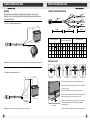
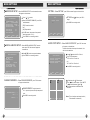
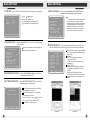
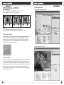
GUARANTEE CARD
ITEM:
MODEL:
DATE OF PURCHASE:
CLIENT NAME:
ITEM NO.:
CONTACT ADDRESS:
CONTACT TEL
IMPORTANT NOTICE
1. Please fill out the Guarantee Card strictly according to the facts;
2. Only will this Guarantee Card be valid when sealed by our
franchisers;
3. We provide 1 year warranty to the product. If product fails to
work properly under warranty period, our factory will help
repair it free of charge;
4. This limited warranty does not apply to:
(1). Damage to a product that is out of warranty;
(2) . Cosmetic damage, such as scratches, nicks and dents;
(3). Damage caused by accident, abuse, misuse, water, flood,
fire, or other acts of nature;
(4). Damage caused by service performed by anyone who is
not an authorized service provider;
(5). Damage to a product that has been modified or altered
without permission;
(6). Damage to a product that has been used in damp, high/low
temperature or any other harsh environments;
(7). Any other damages that are not caused by our factory.
5. Please keep the Guarantee Card properly. We reserve the right
to Refuse warranty in case of no Guarantee Card provided.
The instruction applies to VR8800 series products. Please read it carefully before
using the products!
DIRECTION BEFORE USE
ATTENTIONS
DIRECTION BEFORE USE
A TTE N TIO N S ........... ........... ........... .......... ........... ........... ...................... .......... .... ...
FU N CTI ON S UM MAR Y ...... .......... ........... ........... ..................... ........ ... ........... .........
A P P LIC ATIO N S ........ ..................... ........... ........... .......... ........... ........... ........... ......
P A C K IN G LIS T... ........... ........... .......... ........... ........... ........... .......... ........... ........... ..
TE C H NI CA L P A R AME TE R S..... ........... ........... ........... .......... ........... ........... ........... ..
IN TE R FAC E E X P LA N A TIO N......... ........... ........... ........... ........... .......... ........... .........
C O NN E CTIN G D IAG R A M...... ........... ........... ........... .......... ........... ........... ........... .....
W IR IN G ........ ........... ..................... ........... ........... ........... .......... ........... ........... .......
C O NTR OL W IR E SK E TC H MA P .......... ........... .......... ........... ........... ...................... ...
IN D IC A TOR INS T RU C TIO N S .......... ........... ........... .......... ........... ........... ........... ......
R E MO TE O P E R A TIO N .......... ........... ........... .......... ........... ........... ........... .......... ......
H A R D D RI VE . .......... ...................... ........... ........... .......... ........... ........... ........... .......
02
02
02
03
04
05
06
07
08
09
10
11
MENU SETTINGS
ME N U I NS TR U C TIO N. .......... ........... ........... ........... .......... ........... ........... ........... .....
C A ME R A S E TU P .... ........... .......... ........... ........... ........... .......... ........... ........... .........
R E C OR D S E TU P .... ........... ........... .......... ........... ........... ........... ..................... .........
R E C OR D FR A M E R A TE ... ........... ........... ........... .......... ........... ........... ........... ..........
V ID E O Q U A LITY . ........... ........... ........... ..................... ........... ........... ........... .......... .
R E C OR D S C H E D U LE ... ........... .......... ........... ........... ........... .......... ........... ........... ...
S E N S O R S E TU P ........... ........... ........... ........... .......... ........... ........... ........... .......... ..
S E NS O RE D R E CO RD T IM E ...... ........... ..................... ........... ........... ........... .......... .
A LA R M O N TIME .......... ........... ........... .......... ........... ........... ........... .......... ........... .
V ID E O LO S S S E TU P ....... ........... .......... ........... ........... ........... .......... ........... .........
H/W S E NS O R S E T UP ... ........... ........... ........... .......... ........... ........... ........... .......... .
MO TIO N D E TE C T S ET TUP . ........... ........... .......... ........... ........... ........... .......... .......
H A R D D RI VE S E TU P .......... .......... ........... ........... ........... .......... ...................... ........
MI S CE L LA N E O US S E TU P. .......... ........... ........... ........... .......... ........... ........... .........
CH A NG E P A S S W O R D. .. ........... .......... ........... ........... ........... ........... .......... ...........
S E T T IM E .... ........... ........... .......... ........... ........... ........... .......... ........... ........... ....
A UD IO S E T UP .... ........... ........... ........... .......... ........... ........... ........... .......... .........
P TZ S E TU P ........... ........... .......... ........... ........... ........... .......... ........... ........... ......
L AN G U A G E S E TU P . .......... ........... ........... ........... .......... ........... ........... ........... ......
US E P A S S W O RD LO GIN ... ........... ..................... ........... ........... ........... .......... ..
GP S TIME ZO N E S E TU P .......... ........... ........... ........... .......... ...................... ........
V I DE O S TA N D A R D ...... .......... ........... ........... ........... .......... ........... ........... .........
N E TW O R K S E TU P ........ ........... ........... ........... .......... ........... ........... ........... .......... ...
ID S E TUP .. ........... ........... ........... .......... ........... ........... ........... .......... ........... ..........
R E S E T M E NU .......... ........... .......... ........... ........... ........... .......... ........... ........... .......
12
12
12
13
13
13
14
14
14
14
14
14
15
15
15
15
16
17
17
17
17
18
18
19
19
DIRECTION FOR USE ...................................................................................... 20-2 2
GPRS TRACKING ........................................................................................... 2 3 -26
QUALITY WARRANTY ......................................................................... BACK COVER
1
1. Connect all the accessories before power on;
2. Disconnect the power when insert or remove the HDD, for avoiding HDD damaged;
3. Disconnect the power when connect or remove the cameras, for avoiding cameras damaged;
4. Collision will make HDD permanent damage;
5 . Please keep away the units away from water or liquid;
6 . Do not press bottons simultaneously or operate it abnormally, frequenty when the machine is
working.
FUNCTION SUMMARY
VR8800 series products (VR8800N, VR8800, VR8800G, and VR8800GP) are the next
generation, high-performance, 4-Channel D1 mobile DVR. It uses the MPEG-4 video
compression technique. The video resolution can be up to 720X576@50FPS (PAL) or
720X480@60FPS (NTSC) (over all 4 channels). It is a real-time, high-definition, lowpower-consumption and easy-operation professional vehicle DVR with large memory
capacity. The VR8800 series products are compatible with any CCD/CMOS cameras,
supports a maximum of 1 2.5" 1000GB SATA HDD. The video clips are stored on the HDD.
Users can view them through a TV or a monitor any time, or they can copy the video from the
HDD to a computer. The VR8800GP also supports GPS and GPRS, thus making it possible
for GPS tracking of vehicles. Because of this new feature, the user is able to know exactly
the real-time location, the running route, also the history trace of his (her) vehicle. And this
powerful GPS tracking can be easily realized by cell phone, or PC (software).
1. Immdiately auto record once power on;
2. Support 1000GB SATA HDD;
3. Overwriter when full or stop when full;
4. All files saved in HDD won't be lost when power off;
5. The date/time and ID stamp will be shown on the video;
6. Be compatitable with any CCD/CMOS cameras;
7. Can supply power to the camera directly;
8. Embeded CPU and Linux operation system;
9. Data exchange with PC via USB interface;
10. Anti-shake design, for protecting HDD;
11. Password access makes HDD date safe;
12. Options for continuous, real-time record or motion detect;
13. Clear shut down for HDD safe;
14. Support PAL/NTSC TV system;
15. Multi-language operation menu, plug in and play, no need software installation;
16. Online upgrade is avaliable;
17. This model has integrated real-time tracking capabilities, using GPS.
18. The real-time longitude, latitude and car moving speed will be stamped on the
video image;
19. With GPRS data transmission function, the real-time position of the vehicles can be
tracked by mobile phone or computer.
APPLICATIONS
VR8800 series products (VR800N, VR8800, VR8800G, VR8800GP) are widely used
4-channel HDD mobile DVR, using LINUX embedded systems.
Specifically designed for use in a motor vehicle of any kind, but can also be used quite
easily for other applications.
2
DIRECTION BEFORE USE
PACKING LIST
TECHNICAL PARAMETERS
2. One User's Manual;
1. One 4-CH DVR Mainframe;
Model
VR8800N
NO 3.5" TFT display, NO control box, NO GPS, NO GPRS
VR8800
With 3.5"TFT display, with control box, NO GPS, NO GPRS
VR8800G
With 3.5"TFT display, with control box, with GPS, NO GPRS
VR8800GP With 3.5"TFT display, with control box, with GPS, with GPRS
Working Voltage
4Keys(2 pcs);
3. AVP Combined Wire(4pcs);
Maximum
Current
6. One Remote Control;
5. AV Output Wire(1pcs);
DC8V~DC36V
(must be DC14V~DC36V when power camera directly)
VR8800N
400 +
- 20mA( Main frame )
VR8800
450 +
- 20mA( M ain fram e)
VR8800G
500 +
- 20mA( M ain fram e)
VR8800GP
560 +
- 20mA( M ain fram e)
Working Tempreture
-10C~+50C
O utput V oltag e(F or Cam era)
DC12V
Power Supply
Car battery
Maxim um M emo ry Capac ity
1000GB SATA HDD
Compression File Format
MPEG2/ MPEG4
Record Mode
Boot Record (default), Metion detect, schedule record
and manual record
7. One Power Wire;
8. One Combine wire for controlling ;
红色
黑色
黄色
绿色
9. One GPS Antenna
( Not for VR8800N and V R 8800) ;
11. One Control Box;
10 . One GPRS Antenna
( Only for VR8800GP) ;
12. Four Bolt Groups.
Record Quality
High/Standard/Low
Resolution
D1(PAL 720*576,NTSC 720*480)
Frame Rate
PAL(1~50fps optional), NTSC(1~60fps optional)
Record AV out Signal
4CH Audio+ 2CH Video
File Store Mode
Overwrite when full or stop when full
Internet Interface
One 10M/100M RJ45
Alarm Output
Can connect alarm with audio and light
HDD Interface
One 2.5"SATA HDD interface
Compatible Camera
Common CMOS & CCD
Dimension
180(L)mm*50 ( W) mm*194( H) mm
Net Weight
2.2KG
Notes:
1. In case there is being alteration to the product, pardoning does not notify separately.
3
4
DIRECTION BEFORE USE
DIRECTION BEFORE USE
INTERFACE EXPLANATION
CONNECTING DIAGRAM
LOCK
LOCK
Camera
USB
Fan
White Port : audio
Yellow Port: video
Black Port : power
AV INPUT 2
AV INPUT 1
AV INPUT 3
Camera
TV OUTPUT
AV INPUT 4
AV4
PO WE R
AV3
AV2
AV1
Video
TV
GPRS ANT
GPS ANT
POWER AND CONTROL WIRE JACK
. . . ..
RJ45
Audio
TV/Monitor
COMBINE WIRE FOR CONTROLLING
3.5 QUAD-VIEW DISPLAY
AV4
AV3
AV2
AV1
TV
GPRS
POWER
ANT
REC
STOP
MUTE
RJ45
GPS
2.5"HDD
PLAY
MENU
UP
LEFT
ANT
OK
4 pin
DOWN
Connet ctronal box
RIGHT
6 pin
ALL
Connet input alarm
FULL SCREEN OF CH1
5 pin
Connet output alarm+485PTZ control wrie
FULL SCREEN OF CH2
FULL SCREEN OF CH3
Combine wire for controlling
FULL SCREEN OF CH4
Note: The picture is for reference only , please refer to the actual product for appearance.
5
Power and control combine wire
6
DIRECTION BEFORE USE
DIRECTION BEFORE USE
WIRING
This manual considers the case where the power source is a
battery, and corresponding detailed wiring diagrams are shown in
the figures below.
CONTROL WIRE SKETCH MAP
6 pin
15 pin
6 pin
5 pin
5 pin
1. Wiring for automatic power on/off:
4 pin
Black-
Red+
-
+
4 pin
80cm
5 Core
(485Port and alarm output)
4Core(Control Box)
Green-
Yellow+
Car Accumulator
-
C olour
Pin
N umber
+
50cm
16cm
6Core(Alarm input)
Black White Red Gre en Black Brow n Red Orang e Yellow Black Brow n Red Orange Yellow Gree n
1
2
3
4
1
2
3
4
5
1
2
3
4
5
6
Function REC-LED VCC3.3 IR -IN G ND ALR-out1ALR-out2 G ND RS485+ RS485- ALR-in1 ALR-in2 ALR-in3 ALR-in4 ALR-GND ALR-GND
DB15
7
8
12
11
1
6
13
14
15
2
3
4
5
9
10
Cigar lighter
Attention: The system will power on automatically and start recording when the car ignited .
INSTALLATION
2. wiring for manual power on/off:
Black-
picture(1)
Red+
Picture (2)
Picture(3)
Picture(4)
Picture(5)
Step 1: Install the rubber air sac as shown in Picture (1);
+
-
Step 2: Install the nut and gasket in the order, as shown in
picture (2) and (3);
Here, the installation of the first bolt group finished;
Step 3: The installation of the other three bolt groups is the
same to the first group, as shown in step 1 and 2;
Green-
Car Accumulator
Yellow+
Picture(6)
Attention: Power on/off the system by turning on/off the switch.
7
Step 4: As shown in picture (4) and (5), this is to simulate
the situation when the DVR is installed using the bolt
mounting groups.
Notes: The order of installation is presented in Picture (6).
8
DIRECTION BEFORE USE
DIRECTION BEFORE USE
INDICATOR INSTRUCTIONS
REMOTE CONTROL
IR
Power State
IR: Remote control IR LED.
Power Indicator: Flash once power on.
State Indicator: Flash during record,play back and backup data.
REC
Record key
MENU
Menu key (enter menu or back to previous menu)
OK
Confirm
PLAY
Play/pause
STOP
Stop key
Up key
D own key
Left key
Right key
Fast rewind
KEY
Up key
Down key
Fast forward
1
C hannel 1 full screen display/Button 1
2
C hannel 2 full screen display/Button 2
3
Channel 3 full screen display/Button 3
Left key
Channel 4 full screen display/Button 4
Right key
5
Button 5
Confirm
6
Button 6
Menu key (enter menu or back
to previous menu)
Quad-view display
Play/pause
Pause
Mute
Stop key
Record key
Quad-view display
Mute
No use
No use
Notices: "
5 " and " 6 " are not available. The remote control must be used when entering
the numbers 5 and 6 in passwords.
Channel 1 full screen display/Button 1
Channel 2 full screen display/Button 2
Channel 3 full screen display/Button 3
Channel 4 full screen display/Button 4
CONTROL BOX
REC
STOP
Power indicator
Record indicator
REC Button: Start recording.
STOP Button: Stop recording.
IR Remote
Power indicator: The LED is on (red) when the DVR is power on;
Status indicator: The LED flash (green) when the DVR is recording; The LED is on (green)
when the DVR is playing back.
9
10
DIRECTION BEFORE USE
MENU SETTINGS
HARD DRIVE
MENU INSTRUCTION
Press "MENU" to enter MAIN MENU. The options listed as shown in the following picture:
HDD
Static or collision may cause permanent damage.
Please do not hit the HDD or touch the metal part of the HDD.
Disconnect the power when insert or remove the HDD.
Do not keep the machine working under shaky or dusty circumstance.
MAIN MENU
CAMERA SETUP
RECORD SETUP
RECORD FRAMERATE
VIDEO QUALITY
RECORD SCHEDULE
SENSOR SETUP
HARD DRIVE SETUP
MISCELLANEOUS SETUP
NETWORK SETUP
ID SETUP
RESET MUNU
(
Press " " / " " to select option;
Press "OK" to enter;
Press "MENU" to save settings and exit.
HIGH
)MOVE ( )SELECT ( )EXIT
Note:
( )EXIT=MENU
HARD DRIVE INSTALLTION
CAMERA SETUP-- Select"CAMERA SETUP" on main memu, Press "OK" to enter
the page as shown below:
1 ON
ON: Turn the cameras on;
OFF: Turn the cameras off;
Press" "/" "/" "/" " to select camera;
Press "OK" to switch between "ON" and "OFF";
Press "MENU" to save settings and exit.
2 ON
CAMERA SETUP
HDD
3 ON
(
4 ON
)MOVE ( )SELECT ( )EXIT
RECORD SETUP-- Select"RECORD SETUP" on main menu, Press "OK" to enter
the page as shown below:
1 ON
Unscrew the cover of the hard disk bay with hand and connect the HDD to the
flat cable inside;
Put the HDD in the hard disk bay as shown in the photo;
Screw the cover again and don't over tighten the screws.
2 ON
RECORD SETUP
3 ON
4 ON
ON: Turn camera recording on;
OFF: Turn camera recording off;
Press " "/" "/" "/" " to select camera;
Press "OK" to switch between "ON" and "OFF";
Press "MENU" to save settings and exit.
Notes: The newly-installed hard drive will be required being formatted. Just press OK
button to format, then hard drive can be used.
(
11
)MOVE ( )SELECT ( )EXIT
12
MENU SETTINGS
MENU SETTINGS
RECORD FRAMERATE --Select"RECORD FRAMERATE" on main menu,
press"OK" the screen will appear as shown below.
1 7FPS
2 7FPS
RECORD FRAMERATE
TOTAL
3 7FPS
(
28FPS
4 7FPS
)MOVE ( )+
( )- ( )EXIT
SENSOR SETUP --Select"SENSOR SETUP" on main menu, press"OK"the screen
will appear as shown below:
Frame options for each channel:
PAL: 1, 2, 3, 4, 5, 6(default), 7, 9, 1, 16,
25 (total 50 fps)
NTSC : 1, 2, 3, 4, 5, 6, 8 (default), 10 , 15 , 20 ,
30 (total 6 0 fps);
press " "/" "/" "/" " to select channel;
Press "OK" to confirm the FPS(1-30FPS);
Press "MENU" to save setting and exit to
main menu.
SENSOR SETUP
SENSORED RECORD TIME
ALARM ON TIME
VIDEO LOSS SETUP
H/W SENSOR SETUP
MOTION DETECTOR SETUP
(
10
OFF
Press" "/ " " to select, press"OK"to setup.
)MOVE ( )SELECT ( )EXIT
"SENSORED RECORD TIME": 5s,10s,15s,2 0s,25s a nd 30s a re optional, press"OK" to
s elect;
VIDEO QUALITY SETUP --Select"VIDEO QUALITY SETUP", press"OK" enter
into submenu as below:
There are three options: HIGH/NORMAL/LOW;
Press "OK" to select the quality level you need;
Press "MENU" to save settings and exit.
MAIN MENU
CAMERA SETUP
RECORD SETUP
RECORD FRAMERATE
VIDEO QUALITY
RECORD SCHEDULE
SENSOR SETUP
HARD DRIVE SETUP
MISCELLANEOUS SETUP
NETWORK SETUP
ID SETUP
RESET MUNU
(
"ALARM ON TIME": On,Off,5s, 1 0s,15s , 20s, 25 s and 30s are o ptional, press"OK" to select;
"VIDEO LOSS SETUP": On an d Off are optional, p ress"OK" to select;
"H/W SENSOR SETUP": Press"OK", the screen will appear a s sho wn in picture (1;
"Not Installed", "Normal-Open"and"Normal-Close" are o ptional, press"OK" to select.
1
HIGH
Camera-1
Camera-2
Camera-3
Camera-4
2
Normal-Open
Not installed
Not installed
Not installed
3
Motion Detector Setup
Camera - 1
Camera - 2
Camera - 3
Camera - 4
4
)MOVE ( )SELECT ( )EXIT
(
)MOVE ( )SELECT ( )EXIT
(
)MOVE ( )SELECT ( )EXIT
(2)
(1)
RECORD SCHEDULE --Select"RECORD SCHEDULE" on main menu,press"OK"the
screen will appear as shown below.
RECORD SCHEDULE
Press" "/" " to select time slot (0:00-23:00
avaliable).
Press "OK" to change record mode.
AM
PM
0 . . 3 . . 6 . . 9 . . 0 . . 3 . . 6 . . 9 . .
S
NO-RECORD
RECORD
S SENSOR-RECORD
(
AREA
AREA
AREA
AREA
)MOVE ( )SELECT ( )EXIT
S
NO-RECORD
RECORD
SENSOR-RECORD
Press "MENU" to save setting and exit.
" MOTION DETECTOR SETUP " : press"OK", the screen will appear as shown
in picture (2) ;
Press" "/" "/" "/" " to select the AREA.
Press"OK", the screen will appear as shown
in picture(3);
Motion Detector Camera 2 Sensor :0 :1 :2 :3
Different shape represents different sensitivity.
:0 Disable.
:2 Normal .
:1 Weak
:3 Very sensitive
press " "/" "/" "/" " to select area;
Press stop to modify sensitivity;
Press" MENU" to save setting and exit.
(
)MOVE ( )SELECT ( )EXIT
(3)
13
14
MENU SETTINGS
MENU SETTINGS
HARD DRIVE SETUP --Select"HARD DRIVE SETUP" on main menu,the screen
will appear as shown below :
HARD DRIVE SETUP
OVERWRITE ENABLED
[YES]
Hard
:HTS541680J9SA00
MASTER HDD SIZE
80072MB
MASTER HDD USED
17MB 0%
MASTER HDD FORMAT
SLAVE HDD SIZE
SLAVE HDD USED
SLAVE HDD FORMAT
(
N/A
N/A
)MOVE ( )SELECT ( )EXIT
Press " "/" " to select;
Select "OVERWRITE ENABLED", press OK to
switch between:
[YES]: Overwrite enabled;
and
[NO]: Stop when full
For HDD format, the password is requested
(default password:111111);
Press "MENU" to save setting and exit.
MISCELLANEOUS SETUP -- Select"MISCELLANEOUS SETUP" on main
SET TIME— —Select"SET TIME", press "OK"t he screen will sppear, as shown below :
SET TIME: Press" "/" "to select , press"OK" to
TIME
2010/06/08
change;
Press "MENU" to save setting and exit .
08:08:88
()MOVE ( ) CAM ID ()SELECT ( )EXIT
AUDIO PORT SETUP— —Select"AUDIO PORT SETUP", press "OK" the screen
will appear, as shown below :
This manual considers the setup to the channel 1, the
details are shown below:
menu, press"OK", the screen will appear as
shown below:
MISCELLANEOUS SETUP
Press" "/" "to select correspond submenu;
Press "MENU" to save setting and exit.
AUDIO PORT SETUP
CHANGE PASSWORD
SET TIME
AUDIO PORT SETUP
PTZ SETUP
LANGUAGE
ENGLISH
USE PASSWORD LOGIN
GPS TIME ZONE SETUP
VIDEO STANDARD
NTSC
(
AUDIO PORT1-VIDEO CHANNEL
AUDIO PORT1-RECORD
AUDIO PORT 2 -VIDEO CHANNEL
AUDIO PORT 2 -RECORD
[ 1]
[NO]
[ 2]
[NO]
)MOVE ( )SELECT ( )EXIT
(
CHANGE PASSWORD— —Select" CHANGE PASSWORD", press "OK" the screen
)MOVE ( )SELECT ( )EXIT
1
2
3
4
will appear as shown below :
CHANGE PASSWORD: The original password is
PASSWORD CURRENT [------]
NEW
[------]
CONFIRM [------]
15
Press " "/" " to select Audio Port 1-Record,
Press "OK" to switch between:
"YES" : Audio Port 1- Record is on;
and
"NO" : Audio Port 1- Record is off;
Press "MENU " to save setting and exit.
111111. Input the old password, then input newpassword
twice;
Press "MENU" to save setting and exit .
(
)MOVE ( )SELECT ( )EXIT
" " indicate audio ." " indicate mute.
Press " "/" "to select camera . Press "MUTE"
or " " to switch between" "and " ".
The same operation can be made to the
channel 2.
Notes: This unit only has one channel audio in(
Either channel 1or channel 2).
16
MENU SETTINGS
MENU SETTINGS
PTZ SETUP - -Select "PTZ SETUP", press"OK"the screen will appear, as shown below:
VIDEO STANDARD— — Press "OK" to switch between PAL and NTSC then the
Press " "/" " to select;
Press"OK"to change value;
ID means the ID of corresponding PTZ ;
Press "MENU" to save setting and exit.
PTZ SETUP
SPEED
PROTOCOL
CAMERA- [1]
[ 9600]
[PELCO-D]
ID- [1]
system will be back to preview mode automatic ally.
MISCELLANEOUS SETUP
CHANGE PASSWORD
SET TIME
HDDEN CHANNEL
[OFF]
AUDIO PORT SETUP
PTZ SETUP
LANGUAGE
ENGLISH
USE PASSWORD LOGIN
GPS TIME ZONE SETUP
VIDEO STANDARD
NTSC
Note:
1. This setup comes into effect immediately.
It is not necessary to restart the system.
2. Make sure the four cameras are the same
TV standard when they are used together.
3. Make sure the DVR is set to the same
standard as the cameras. Failure to do so
will result in no picture being recorded.
()MOVE ( ) CAM ID ()SELECT ( )EXIT
(
)MOVE ( )SELECT ( )EXIT
LANGUAGE SETUP— —Select" LANGUAGE SETUP ", press "OK" the screen will sppear,
as shown below:
MISCELLANEOUS SETUP
Press"OK" to switch between Chinese and English;
Press"Menu" to save setting and exit.
CHANGE PASSWORD
SET TIME
HDDEN CHANNEL
[OFF]
AUDIO PORT SETUP
PTZ SETUP
LANGUAGE
ENGLISH
USE PASSWORD LOGIN
GPS TIME ZONE SETUP
VIDEO STANDARD
NTSC
(
NETWORK SETUP— —User can remote monitor DVR after network setup done.
Select NETWORK SETUP on main menu, press "OK" to enter submenu as shown below:
NETWORK SETUP
MAC ADDRESS..
IP ALLOCATON
IP ADDRESS ...
SURNET MASK..
GATEWAY ... ...
DNS1 ADDRES S .
DNS2 ADDRES S .
HTTP PORT... .
USER SETTI NG...
DDNS SE TTING.. .
)MOVE ( )SELECT ( )EXIT
(
<66. 66.66.66.66 .66 >
[STATICI]
[0. 0.0.0]
[0.0.0.0]
[0.0 .0. 0]
[0.0.0.0]
[ 0.0.0.0 ]
[ 80]
)MOVE ( )SELECT ( )EXI T
USE PASSWORD LOGIN— —Select "USE PASSWORD LOGIN", press "OK" to
switch between "ON" and "OFF" .
MAC: DVR's ID on internet, user can set MAC
at will. The system will assign MAC address
automatically ;
IP options:
DHCP: the system gains necessary
network info(default)
STATIC: request user input necessary
Network info;
USER SETTING
Administer: can remote view and control
system.(default ID:ADMIN, Password:
ADMIN)
Guest(User): can only remote view
video.(default ID:NULL, Password: NULL)
Restart DVR after all settings done to save
settings.
GPS TIME ZONE SETUP-- Select" GPS TIME ZONE SETUP ", press "OK" the
screen will appear, as shown below :
GPS TIME ZONE SETUP
Longitude
(
17
17
E
TIMEZONE 08
Press"OK" to switch between E(east) and W(west),
Press" "/" " to select time zone;
Press "OK" to change tim e zone (0~12a djus t able).
For example t o set east 8 zone.
Press "OK" to s elect "E" , press " "/" " to selec t time
zone. Pres s "OK" to change time zone to be "8";
Press "M ENU" to save setting and exit.
)MOVE ( )SELECT ( )EXIT
Picture (4)
Picture (5)
18
MENU SETTINGS
ID SETUP— —S elect "ID S ETU P ", P R E SS "OK " th e p age w ill be sh own on the sc reen
as s ho wn in pic ture (6). A gain pres s "O K" the scree n will ap pea r as
s hown in picture (7) .
ID
ID
SETUP
.....
ID
[ABC01234]
SETUP
ABC01234
D
0
1
2
3
4
5
6
7
8
()MOVE ( ) CAM ID ()SELECT ( )EXIT
()MOVE ( ) CAM ID ()SELECT ( )EXIT
picture (6)
picture (7)
On picture (7) , press " "/" " to select the position. The position press " "/"
Press " MENU" to save setting and exit .
" to set value .
DIRECTION FOR USE
1. Connect all necessary parts then powe r on;
2. Turn on : For autom atic pow er on . The DVR will turn on autom atically w hen the car is ignited. O therw ise,
we need to sw itc h o n the unit by hand.
3. REC :1. Start re co rd ing when p ower on ; 2. Pre ss REC to rec ord in previe w m ode, an d press "STO P" to
s top rec ording.
4. Pla y b ack: In preview m ode(not recording),pre ss "PLAY"to playback the latest vid eo file;I n playback
s tate, pre ss "M ENU"for vide o file list, press" "/ " "to select the video file , a nd pres s"PLAY" to
play back, pres s" MENU "to back to previous menu.
5. PTZ Setup: In preview or rec ordin g s tate (full s creen), p ress"OK"to enter into su bm enu, again press "OK"
button c an widen/narrow view angle; press " "/ " " can m ak e the cam era sway to left o r right,
Press " "/ " " to up or down,press an y key to stop PTZ control, press"M EN U"to ex it.
6. In preview or rec ording s tate, the G PS data appears o n the top left co r ner;G PS data co nsists of
longitude , latitude, radial v elocity.
7. Remote Network monitoring.
The three pictures of Remote Network monitoring are shown as follow: Conneted State,
Capture Tool, Remote DVR Control Panel.
RESET MENU— —S ele ct"R E S ET ME NU ", P RE S S "OK "the sc reen w ill appear as
sho w n b elow:
RESET MENU
Push DVR system password to reset
every menu configurcetion except of
net work menu and system
Enter the password then reset the system
settings, press "MENU" to sae settings and be
back to Main Menu.
password
**********
( )EXIT
19
20
8. Motion detect setup:
As an example, let's take the door in channel 1 during 9am to 12am:
(1). On main menu, select RECORD SCHEDULE, press OK to enter submenu, set
9am~12am Record mode to be Sensor Record, then press MENU back to Main menu;
(2). On main menu, select SENSOR SETUP, press OK to enter submenu, set SENSORED
RECORD TIME, ALARM ON TIME at will, and open Channel 1 on H/W SENSOR
SETUP page, open Channel 1 on MOTION DETECT SETUP page and set the door
Area's sensitivity in Channel 1 to be 3;
(3). Press Menu back to preview mode;
(4). Press REC key to final confirm motion detect on function;
(5). Motion detect setup done;
(6). Set other channels in the same way or in the same time.
Notes: Kindly check P13 -14 for more detailed information when necessary.
9. Operation after connecting computer:
( 1 ). Copy the PCView_ex1082(1).exe to the local PC;
( 2 ). Turn on the DVR;
( 3 ). Connect the DVR with PC via USB cable;
(4). Run PCView_ex1082(1).exe;
(5). After connecting successfully, 4 channels will playback their lastest videos
automatically;
Operation
Software Icons
Back up
Play
Playback
Fast forward
Open the Browse Folders
Jump to next video clips
Jump back to last video clip
Play frame by frame rewind
Fast rewind
Play frame by frame
Reverse playback
Stream Capture
Pause
BMP Capture
Picture (9)
Picture (10)
(1). Backup
1 . Click" "Backup configuration Message box will pop up, the sceen will be shown as
picture (9);
2 . Set up the backup start and backup ends;
3 . Select the folder from the pc where you would like to save the backup;
4 . You can rename the filename , the backup files will be in .MCG format;
5 . During backup, the progress Dialog will be shown as picture (10), you can
click"cancel" to exit backup;
6 . The"backup done"message box will popup when backup done;
7 . Safely disconnect DVR from the PC;
8 . Click" "on left bottom of the Pcviewer-ex1082(1).exe window to choose and playback
files;
(2). Playback : click " "or " " for the file list, then choose file and playback;
(3). BMP Capture: clip " " will capture picture in BMP format;
(4). Stream Capture: click" " to capture video stream;
(5). Delete: no access to delete any single file on hard disk .
Picture (8)
21
22
GPRS TRACKING(Only for VR8800GP)
1.Install the SIM card
In order to do GPS tracking with VR8800GP, you need to install a SIM
card in VR8800GP. Please refer to the following pictures;
3.1 GP80 software Interface
3.1.1 GP80 Interface (Open Street Map)
Note:
(1). Install the SIM card correctly referring to the pictures above ;
(2). Make sure the SIM card supports GPRS function, and is in active condition.
2. GPS Tracking by Cell Phone
Cell phone tracking is easy. Just make sure there is a SIM card installed in VR8800GP , and
then call the SIM card number. Whenever you call the number, VR8800GP will reply you a
message with the real-time GPS information of the vehicle, including latitude, longitude,
and moving speed, so that you can learn exactly where the vehicle is and what place it is
heading for. See following picture for reference;
Latitude=23 35 30.50N
Longitude=123 59 46.61E,
Speed= 70.54Km/h,
2010-08-05,
13:30
3.1.2 GP80 Interface (Satellite Map)
3. GPS Tracking by PC
To do this, you need to buy a software called GP80 from us and use it with VR8800GP. This
software can be used in Windows 98, Windows 2000, Windows XP and other operating
systems and will be able to draw on the Map (you can select satellite map, Open Street map
or other kinds of map) the real-time location, the running route, and also the history trace of
the vehicle. With the help of the software, the administrator can easily know where the
vehicle is, what place it is heading for, and also where it has been. Please refer to the User's
Manual of GP80 for more details.
23
24
25
3.2 Real-time Tracking
3.2.1 Real-time Tracking (Open Street)
3.3 History Tracking
3.3.1 History Tracking (Open Street)
3.2.2 Real-time Tracking (Satellite)
3.3.2 History Tracking (Satellite)
26