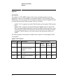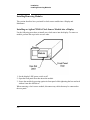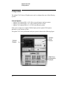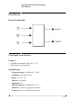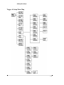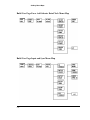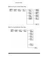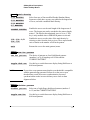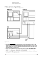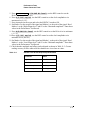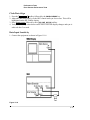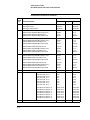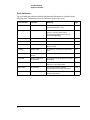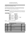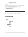
1
Agilent 71612 Series of Gb/s Testers
Operating and Programming Manual
SERIAL NUMBERS
This manual applies directly to Agilent 71612 12.5 Gb/s Error Performance Analyzers
comprising the following elements:
Agilent 70843
Option UHF 0.1-12.5 Gb/s Error Performance Analyzer with serial
number(s) prefixed 3xxxU or GBxxxxxxxx.
Agilent 70843
Option UHG 0.1-12.5 Gb/s Pattern Generator with serial number(s)
prefixed 3xxxU or GBxxxxxxxx.
Agilent 70843
Option UHH Error Detector with serial number(s) prefixed 3xxxU or
GBxxxxxxxx.
For additional important information about serial numbers, see SERIAL NUMBER
INFORMATION on page 1-9 in the Operating Manual.
Serial number information for other elements in the system is contained in the following
manuals:
Display
see Agilent 70004A Installation and Verification Manual.
Clock Source
see Agilent 70340A Operating and Calibration Manual.
© Copyright (2000, 2001, 2002) Agilent Technologies Ltd.
Agilent Part No. 71612-90023
Printed in U.K. July 2002
DECLARATION OF CONFORMITY
According to ISO/IEC Guide 22 and CEN/CENELEC EN45014
Manufacturer’s Name:
Manufacturer’s Address:
Agilent Technologies UK Limited
Telecomms Networks Test Division
South Queensferry
West Lothian, EH30 9TG
Scotland, United Kingdom
Declares that the product
Product Name:
0.1-12.5 Gb/s Error Performance Analyzer
Model Number:
70843C
Product Options:
This declaration covers all options of the above product as detailed in
TCF A-5951-9852-01.
EMC:
Conforms with the protection requirements of European Council Directive 89/336/EEC on the approximation of the
laws of the member states relating to electromagnetic compatibility, against EMC test specifications EN 55011:1991
(Group 1, Class A) and EN 50082-1:1992.
As Detailed in:
Electromagnetic Compatibility (EMC)
Technical Construction File (TCF) No. A-5951-9852-01
Assessed by:
DTI Appointed Competent Body
EMC Test Centre,
GEC-Marconi Avionics Ltd.,
Maxwell Building,
Donibristle Industrial Park,
Hillend,
Dunfermline
KY11 9LB
Scotland, United Kingdom
Technical Report Number:6893/2200/CBR, dated 21 August 1997
Safety:
The product conforms to the following safety standards:
IEC 61010-1(1990) +A1(1992) +A2(1995) / EN 61010-1:1993
IEC 60825-1(1993) / EN 60825-1:1994
Canada / CSA-C22.2 No. 1010.1-93
The product herewith complies with the requirements of the Low Voltage Directive 73/23/EEC, and carries the CE
mark accordingly.
South Queensferry, Scotland.
01 June 2001
Robert Tait
Product Regulations Manager
For further information, please contact your local Agilent Technologies sales office, agent, or distributor.
Europe Contact:
Your Local Agilent Technologies Sales and Service Office or Agilent Technologies Deutschland GmbH, Herrenberger Strasse 130,
71034 Boeblingen (Fax: +49-7031-143143)
DECLARATION OF CONFORMITY
According to ISO/IEC Guide 22 and CEN/CENELEC EN45014
Manufacturer’s Name:
Manufacturer’s Address:
Agilent Technologies UK Limited
Telecomms Networks Test Division
South Queensferry
West Lothian, EH30 9TG
Scotland, United Kingdom
Declares that the product
Product Name:
12.5Gb/s Error Performance Analyzer System
Model Number:
71612C
Product Options:
This declaration covers all options of the above product as detailed in
TCF A-5951-9852-01.
EMC:
Conforms with the protection requirements of European Council Directive 89/336/EEC on the approximation of the
laws of the member states relating to electromagnetic compatibility, against EMC test specifications EN 55011:1991
(Group 1, Class A) and EN 50082-1:1992.
As Detailed in:
Electromagnetic Compatibility (EMC)
Technical Construction File (TCF) No. A-5951-9852-01
Assessed by:
DTI Appointed Competent Body
EMC Test Centre,
GEC-Marconi Avionics Ltd.,
Maxwell Building,
Donibristle Industrial Park,
Hillend,
Dunfermline
KY11 9LB
Scotland, United Kingdom
Technical Report Number:6893/2200/CBR, dated 21 August 1997
Supplementary Information:
The individual components of the product meet relevant international safety standards.
The product herewith complies with the requirements of the Low Voltage Directive 73/23/EEC, and carries the CE
mark accordingly.
South Queensferry, Scotland.
01 June 2001
Robert Tait
Product Regulations Manager
For further information, please contact your local Agilent Technologies sales office, agent, or distributor.
WARNINGS
The following general safety precautions must be observed during all phases of operation, service, and
repair of this product. Failure to comply with these precautions or with specific warnings elsewhere in this
manual violates safety standards of design, manufacture, and intended use of the product. Agilent Technologies assumes no liability for the customer's failure to comply with these requirements.
This is a safety Class 1 instrument (provided with a protective earthing ground, incorporated in the powercord). The mains plug shall only be inserted in a socket outlet provided with a protective earth contact. Any
interruption of the protective conductor inside or outside of the instrument is likely to make the instrument
dangerous. Intentional interruption is prohibited.
DO NOT operate the product in an explosive atmosphere or in the presence of flammable gasses or fumes.
For continued protection against fire hazard, replace the line fuses only with the same type and ratings (see
.Fuse Ratings on page 2-10). The use of other fuses or materials is prohibited.
Keep away from live circuits: Operating personnel must not remove equipment covers or shields. Procedures involving the removal of covers and shields are for use by service-trained personnel only. Under certain conditions, dangerous voltages may exist even with the equipment switched off. To avoid dangerous
electrical shock, DO NOT perform procedures involving cover or shield removal unless you are qualified to
do so.
DO NOT operate damaged equipment: Whenever it is possible that the safety protection features built into
this product have been impaired, either through physical damage, excessive moisture, or any other reason,
REMOVE POWER and do not use the product until safe operation can be verified by service-trained personnel. If necessary, return the product to an Agilent Technologies Sales and Service Office for service and
repair to ensure the safety features are maintained.
DO NOT service or adjust alone: Do not attempt internal service or adjustment unless another person, capable of rendering first aid and resuscitation, is present.
DO NOT substitute parts or modify equipment: Because of the danger of introducing additional hazards, do
not install substitute parts or perform any unauthorized modification to the product. Return the product to an
Agilent Technologies Sales and Service Office for service and repair to ensure the safety features are maintained.
If this instrument is not used as specified, the protection provided by the equipment could be impaired. This
instrument must be used in a normal condition (in which all means of protection are intact) only.
No operator serviceable parts inside. Refer servicing to qualified personnel. To prevent electrical shock do
not remove covers.
CERTIFICATION
Agilent Technologies certifies that this product met its published specifications at the time of shipment from
the factory. Agilent Technologies further certifies that its calibration measurements are traceable to the
United States National Institute of Standards and Technology (formerly National Bureau of Standards), to
the extent allowed by that organization's calibration facility, and to the calibration facilities of other International Standards Organization members.
WARRANTY
This Agilent Technologies product is warranted against detects in materials and workmanship for a period of
one year from date of shipment. Duration and conditions of warranty for this product may be superseded
when the product is integrated into (becomes part of) other Agilent products. During the warranty period,
Agilent Technologies will, at its option, either repair or replace products which prove to be defective.
For warranty service or repair, this product must he returned to a service facility designated by Agilent Technologies. Buyer shall prepay shipping charges to Agilent and Agilent shall pay shipping charges to return the
product to Buyer. However, Buyer shall pay all shipping charges, duties, and taxes for products returned to
Agilent from another country.
Agilent warrants that its software and firmware designated by Agilent for use with a product will execute its
programming instructions when properly installed on that product. Agilent does not warrant that the operation of the product or software, or firmware will be uninterrupted or error free.
LIMITATION OF WARRANTY
The foregoing warranty shall not apply to defects resulting from improper or inadequate maintenance by
Buyer, Buyer-supplied products or interfacing, unauthorized modification or misuse, operation outside of
the environmental specifications for the products, or improper site preparation or maintenance.
The design and implementation of any circuit on this product is the sole responsibility of the Buyer. Agilent
does not warrant the Buyer's circuitry or malfunctions of Agilent products that result from the Buyer's circuitry. In addition, Agilent does not warrant any damage that occurs as a result of the Buyer's circuit or any
other detects that result from Buyer-supplied products.
NO OTHER WARRANTY IS EXPRESSED OR IMPLIED. AGILENT SPECIFICALLY DISCLAIMS
THE IMPLIED WARRANTIES OF MERCHANTABILITY AND FITNESS FOR A PARTICULAR
PURPOSE.
EXCLUSIVE REMEDIES
THE REMEDIES PROVIDED HEREIN ARE BUYER'S SOLE AND EXCLUSIVE REMEDIES.
AGILENT SHALL NOT BE LIABLE FOR ANY DIRECT, INDIRECT, SPECIAL, INCIDENTAL, OR
CONSEQUENTIAL DAMAGES, WHETHER BASED ON CONTRACT, TORT, OR ANY OTHER
LEGAL THEORY.
NOTICE
The information contained in this document is subject to change without notice. AGILENT
TECHNOLOGIES MAKES NO WARRANTY OF ANY KIND WITH REGARD TO THIS MATERIAL,
INCLUDING, BUT NOT LIMITED TO, THE IMPLIED WARRANTIES OF MERCHANTABILITY AND
FITNESS FOR A PARTICULAR PURPOSE. Agilent shall not be liable for errors contained herein or for
incidental or consequential damages in connection with the furnishing, performance or use of this material.
This document contains proprietary information which is protected by copyright. All rights are reserved. No
part of this document may he photocopied, reproduced, or translated without the prior written consent of the
Agilent Technologies. Agilent assumes no responsibility for the use or reliability of its software on
equipment that is not furnished by Agilent.
Restricted Rights Legend
Use, duplication or disclosure is subject to restrictions as set forth in subdivision (c)(1)(ii) of the Rights in
Technical Data and Computer Software clause at 52.227-FAR14. Agilent Technologies; 3000 Hanover
Street; Palo Alto, California 94304.
Printing History
The Printing History shown below lists all Editions and Updates of this manual and the printing date(s). The
first printing of the manual is Edition 1. The Edition number increments by 1 whenever the manual is
revised. Updates, which are issued between Editions, contain replacement pages to correct the current Edition of the manual. Updates are numbered sequentially starting with Update 1. When a new Edition is created, it contains all the Update information for the previous Edition. Each new Edition or Update also
includes a revised copy of this printing history page. Many product updates or revisions do not require manual changes and, conversely, manual corrections may be done without accompanying product changes.
Therefore, do not expect a one-to-one correspondence between product updates and manual updates.
Edition or
Update
Date
Part Number
Edition or
Update
Date
Part Number
Edition 1
Feb 1994
71612-90000
New Edition
Mar 2000
71612-90011
Edition 2
Jul 1995
71612.90000
New Edition
Mar 2001
71612-90015
New Edition
Jun 1998
71612-90007
New Edition
July 2001
71612-90016
New Edition
Dec 1998
71612-90008
New Edition
July 2002
71612-90023
Agilent 71612 Series of Gb/s Testers
Operating Manual
Contents - Operating Manual
1 General Information
Introduction 1-2
Safety Considerations 1-2
General 1-3
Safety Symbols 1-4
Other Regulatory Markings 1-5
Options 1-6
Introduction 1-6
Upgrade Options 1-8
Accessories Supplied 1-8
Recommended Accessory List 1-8
Serial Number Information 1-9
Returning Instruments for Service 1-9
Packaging Requirements 1-9
Preparing an Instrument for Shipping 1-10
Precautions 1-11
ESD Precautions 1-11
Static-safe Workstation 1-11
Static-safe Accessories 1-12
Lifting/Carrying the Agilent 70843 1-12
Display Cleaning 1-13
Cabinet Cleaning 1-13
How to Update the Agilent 70843 Firmware 1-13
To Update Control Processor Firmware 1-13
To Update Measurement Processor Firmware 1-14
2 Installation
Introduction 2-2
Preparation for Use 2-3
Initial Inspection 2-3
To Fit an Instrument Hardkey Panel 2-3
Statement of Compliance 2-4
Electromagnetic Compatibility (EMC) Information
Safety Information 2-4
Instruction for cleaning 2-4
Operating Requirements 2-4
Operating and Storage Environment 2-4
Physical Specifications 2-5
Cooling Considerations 2-5
2-4
Contents-1
Contents - Operating Manual
Lifting/Carrying the Agilent 70843 2-6
Power Requirements 2-6
Noise Declaration 2-7
Power Cables 2-7
Line Voltage Selection 2-8
Instrument (Agilent 70843) Line Voltage Selector 2-8
Display (Agilent 70004A) Line Voltage Selector 2-8
Line Fuses 2-9
Accessing the Agilent 70843 Line Fuse 2-9
Accessing the Display (Agilent 70004A) Fuses 2-10
.Fuse Ratings 2-10
HP-MSIB Address Switches 2-10
Factory Preset HP-MSIB Addresses 2-11
Agilent 70843 Address Switches 2-11
Agilent 70340A Clock Source Module Address Switches 2-12
Agilent 70004A Display Address Switches 2-12
GPIB Address Switches 2-12
To Change the GPIB Address 2-13
Factory Preset GPIB Addresses 2-13
Bench Operation 2-13
Rack Mount Installation 2-13
System Installation 2-15
Accessories 2-15
Cables 2-15
Connectors 2-15
Terminations 2-15
Procedure 2-16
System Verification 2-18
Error Performance Analyzer System Verification 2-18
Selftest at Power-on 2-19
Installing/Removing Modules 2-20
Installing an Agilent 70340A Clock Source Module into a Display 2-20
3 System Overview
Configurations 3-2
System Options 3-2
Additional System Options 3-3
Agilent 70843 Instrument Options
Documentation Overview 3-3
Contents-2
3-3
Contents - Operating Manual
4 Operating Features and Specifications
Introduction 4-2
Warm-up 4-2
Operating Temperature Specification 4-2
Calibration Interval 4-2
Pattern Generator 4-3
External connections 4-3
Patterns 4-3
PRBS Test Patterns 4-3
Zero Substitution/Variable Mark Density 4-3
Test Patterns 4-3
Zero Substitution 4-4
Variable Mark Density 4-4
User-programmable test patterns 4-4
Alternate test pattern - pattern generator only 4-4
Internal Disk Drive 4-5
Clock Input 4-5
Features 4-5
Specifications 4-5
Data and Data (inverted) Outputs 4-6
Features 4-6
Data output features not controlled by data output softkeys
Specifications 4-6
Data outputs - main 4-6
Error Add 4-8
Clock and Clock (inverted) Outputs 4-8
Specifications 4-8
Clock outputs - main 4-8
Subrate Clock & Data (inverted) Outputs 4-9
Features 4-9
Specifications 4-9
Trigger Output 4-9
Features 4-9
Pattern Mode 4-10
PRBS 2^31-1, 2^23-1, 2^15-1, 2^10-1, 2^7-1 4-10
Alternate pattern 4-10
All other patterns 4-10
Divided Clock Mode 4-10
Interface 4-10
Auxiliary Input 4-10
Alternate Pattern Selected 4-11
Data Output Inhibit (Gating mode) 4-11
4-6
Contents-3
Contents - Operating Manual
Interface 4-11
To Select Oneshot Mode 4-11
To Select Alternating Mode 4-11
Error Inject Input 4-12
Interface 4-12
Status Indicators 4-12
Pattern Generator indicators 4-12
Error Detector indicators 4-12
General instrument indicators 4-12
Rear Panel Switches 4-12
Error Detector 4-13
External connections 4-13
Clock Input (error detector) 4-13
Features 4-13
Specifications 4-13
Data Input 4-14
Features 4-14
Specifications 4-14
Pattern Trigger Output (error detector) 4-14
Features 4-15
Pattern Mode 4-15
PRBS 2^31-1, 2^23-1, 2^15-1, 2^10-1, 2^7-1 4-15
All other patterns 4-15
Divided Clock Mode 4-15
Specifications 4-15
Errors Output 4-15
Features 4-15
Interface 4-16
Gating Input 4-16
Interface 4-16
Automatic Clock-to-Data Alignment 4-17
Introduction 4-17
Definition 4-17
Eye Width 4-17
Automatic 0/1 Threshold Center 4-18
To perform a 0/1 Threshold Centering 4-18
Data Input 0/1 Threshold 4-18
Introduction 4-18
Measurements 4-18
Error Analysis 4-19
Power-loss Seconds 4-19
Sync-loss Seconds 4-20
Frequency Measurement 4-20
Contents-4
Contents - Operating Manual
Result Logging 4-20
Error Location (Agilent 71612 or Agilent 70843 Option UHJ) 4-20
Bit BER 4-20
Measurements 4-20
Error location capture 4-20
Block BER 4-21
Measurement Period 4-22
Measurement Period Features 4-22
Gating modes 4-22
Gating Period Definition 4-23
Burst gating 4-23
Pattern Synchronization 4-24
Synchronization Modes 4-24
Sync Gain Loss Criteria 4-24
Synchronization Times 4-24
Audible Output 4-24
Logging to External Printer 4-25
Functions 4-25
To Set Up Your Own Display of Results or Status Information 4-25
Procedure 4-25
Select and View the User's Page 4-25
To Build Your Own User's Page 4-26
5 Getting Started
Using the Agilent 70004A Display 5-2
Key Notation 5-2
Display Fixed Label Keys 5-3
Instrument Hardkeys 5-3
Parameter Control Keys 5-3
Instrument Softkeys 5-3
Softkeys and Windows Color Coding
Multi-State Functions 5-3
To Set Up the Display 5-4
Display Functions 5-4
Instrument Functions 5-5
System Turn-On 5-6
Introduction 5-6
Making Your First Measurement 5-7
Introduction 5-7
Procedure 5-7
Initial Switch On 5-7
Initial settings 5-7
5-3
Contents-5
Contents - Operating Manual
Perform a data eye measurement 5-8
Eye Edge Threshold 5-9
Automatic 0/1 Threshold Center 5-9
To Select a Measurement Gating Period 5-9
To Start a Measurement 5-9
Viewing Results and Introducing Errors into the System 5-9
To Select a Fixed Error Rate 5-10
To Add External Errors 5-10
Start a New Measurement 5-10
To View Measurement Results 5-10
To Verify/Demonstrate the Capture Error Feature (Option UHJ
instruments) 5-11
Procedure 5-11
6 Softkey Menu Maps
Introduction 6-2
Menu Map when MENU hardkey Selected 6-2
Menu Map when Result Pages hardkey Selected 6-3
Menu Map when Pattern hardkey Selected 6-3
PRBS Menu Map 6-4
Zerosub Menu Map 6-4
Markdensity Menu Map 6-5
Ram User Menu Map 6-5
Disk User Menu Map 6-6
Disk Utils Menu Map 6-6
Edit Ram User Menu Map 6-7
Edit Disk User Menu Map 6-7
Edit User Menu Map 6-8
Data Output Menu Map 6-8
Clock Output Menu Map 6-9
Error Add Menu Map 6-9
Subrate Outputs Menu Map 6-10
Trigger & Setup Menu Map 6-11
Miscellaneous Menu Map 6-12
Input & Eye Menu Map 6-12
Sync & Audio Menu Map 6-13
Gating Menu Map 6-14
Logging Menu Map 6-15
Error Location Menu Map 6-15
Build User Page Menu Map 6-16
Build User Page Pattern & Trigger Menu Map 6-16
Build User Page Data Output Menu Map 6-17
Contents-6
Contents - Operating Manual
Build User Page Clock Output Menu Map 6-17
Build User Page Error Add Subrate Data/Clock Menu Map 6-18
Build User Page Input and Sync Menu Map 6-18
Build User Page Gating and Error Location Menu Map 6-19
Build User Page Logging Menu Map 6-19
Build User Page Main Results Menu Map 6-20
Build User Page Other Results Menu Map 6-20
Build User Page Interval Results Menu Map 6-21
Build User Page G.821 Results Menu Map 6-21
Build User Page Eye Results Menu Map 6-22
Build User Page Big Results Menu Map 6-22
7 Softkey Menu Descriptions
Introduction 7-2
Softkey Menus 7-2
Softkeys requiring numeric entry 7-2
Softkey Labelling 7-2
Softkeys Color Coding 7-2
Primary Softkeys 7-3
Path Selection 7-3
Pattern Softkey Menus 7-4
Path 7-4
Description 7-4
Edit User Pattern Menu (RAM or disk) 7-6
Path 7-6
Description 7-6
disk Utils 7-9
Path 7-9
Description 7-9
Alternate Pattern Control 7-9
Path 7-9
Description 7-9
Data Output Menu 7-11
Path 7-11
Description 7-11
Clock Output Menu 7-13
Path 7-13
Description 7-13
Error Add Menu 7-14
Path 7-14
Description 7-14
Contents-7
Contents - Operating Manual
Subrate Outputs 7-15
Path 7-15
Description 7-15
Subrate Data Softkeys 7-15
Subrate Clock Softkeys 7-15
Trigger & Setup Menu 7-16
Path 7-16
Description 7-16
Pattern Generator Trigger Output 7-16
Error Detector Trigger Output 7-17
Error Detector Errors Output 7-17
Save and Recall Instrument Setup 7-18
Misc Menu 7-18
Path 7-18
Description 7-18
Result Pages Menu 7-22
Path 7-22
Description 7-22
Main Results Display 7-22
Other Results Display 7-23
Intervl Results 7-23
G.821 Results 7-24
Eye Results 7-24
User's Page 7-24
Build User-Page Menu 7-25
Path 7-25
Description 7-25
Pattern & Trigger USER'S PAGE menu 7-26
Data & Clock Output USER'S PAGE menus 7-26
Err-add Subrate USER'S PAGE menu 7-26
Input & Sync USER'S PAGE menu 7-27
Gating Err-loc USER'S PAGE menu 7-27
Logging USER'S PAGE menu 7-27
Main results USER'S PAGE menu 7-28
Other results USER'S PAGE menu 7-29
Interval results USER'S page menu 7-30
G.821 results USER'S PAGE menu 7-31
Eye results USER'S PAGE menu 7-31
BIG results USER'S PAGE menu 7-31
Input & Eye Menu 7-32
Path 7-32
Description 7-32
Contents-8
Contents - Operating Manual
Sync & Audio Menu 7-34
Path 7-34
Description 7-34
Gating Menu 7-35
Path 7-35
Description 7-35
Gating after a Power Loss 7-35
Error Location 7-37
Path 7-37
Description 7-37
Logging Menu 7-38
Path 7-38
Description 7-38
8 User Patterns and Disk Operation
Define, Edit and Store User Defined Patterns 8-2
Introduction 8-2
Basic Editor Operation 8-2
The Editor 8-3
Editor Features 8-3
Pattern Stores 8-3
Current Pattern 8-3
Choosing a Pattern 8-4
RAM-Based File Catalog 8-4
Disk-Based File Catalog 8-4
User Pattern Memory 8-5
Exiting the Editor By Mistake 8-5
Procedure 8-5
How to Set Up and Edit Your Own User Pattern 8-6
Introduction 8-6
To Edit User Patterns 8-6
Procedure 8-6
Set Pattern Length 8-7
Insert/Replace Bits in the Pattern 8-7
Delete Bits 8-7
To Save a Pattern 8-8
Procedure 8-8
To Load a Pattern Store Into the Editor 8-8
Procedure 8-8
To Load a PRBS or User Pattern into the Editor 8-9
Contents-9
Contents - Operating Manual
To Load a Block of Data (PRBS) 8-9
Procedure 8-9
To Edit Zero Substitution 8-9
To Edit Mark Density 8-9
To Load a User Pattern Into the Editor 8-10
Procedure 8-10
Load Copies of User Patterns 8-10
To Save a Block of Data 8-11
Procedure 8-11
To Delete a Block of Data 8-12
Procedure 8-12
Alternate Patterns 8-12
To Select Alternate Pattern Control 8-13
Procedure 8-13
To Generate an Alternate Pattern 8-13
Procedure 8-13
To Load a 2^10 PRBS into Half B of the Alternate Pattern
To Save the Alternate Pattern 8-15
Disk Operation 8-16
Introduction 8-16
Running out of Disk Space 8-16
Unable to Write to Disk 8-17
Disk Organization 8-17
Header String Length 8-18
Header String 8-19
Revision Code 8-19
Pattern Index 8-20
Pattern Label String Length 8-20
Pattern Length 8-20
Trigger Bit 8-20
Type of Pattern 8-20
Pattern Contents 8-20
9 Preset Instrument Configurations
Introduction 9-2
PRESET Instrument Configurations
Preset 1 Configuration 9-8
Preset 2 Configuration 9-10
User Pattern Default Settings 9-11
Contents-10
9-2
8-15
Contents - Operating Manual
10 Data Logging
Introduction 10-2
Recommended Printers 10-2
GP-IB (IEEE-488) to Centronics Printer Interface Converter 10-2
Printer Interface Cables 10-3
Printer Address 10-3
Selecting Logging Functions 10-3
To Log Results to an GP-IB External Printer 10-4
Connecting a Printer 10-4
To Log Results 10-4
To Output Results via GP-IB to a Controller 10-4
Procedure 10-4
When Measurement Results can be Logged 10-4
Logging During Gating 10-5
Logging Trigger Threshold 10-5
Results Logged During Gating 10-5
To Log Results During Gating 10-5
Procedure 10-5
End of Measurement Period Logging 10-6
End of Measurement Logging Trigger 10-6
To Log Results at the End of the Measurement Period 10-6
Log On Demand 10-7
Logging Alarms 10-7
To Log Alarms 10-7
Logging Squelch 10-7
To Squelch or not to Squelch 10-7
Results Storage 10-8
Results Storage when Logging is Switched On 10-8
11 Performance Tests
Introduction 11-2
Test Equipment Required 11-2
Parametric Testing 11-3
Preliminary setup 11-3
Data Risetime 11-4
Data Falltime 11-4
Data Jitter 11-5
Data (inverted) Risetime 11-6
Data (inverted) Falltime 11-6
Data (inverted) Jitter 11-7
Clock Risetime 11-8
Clock Falltime 11-8
Contents-11
Contents - Operating Manual
Clock (inverted) Risetime 11-9
Clock (inverted) Falltime 11-9
Pattern Generator Tests 11-10
Clock Input Minimum Level Alarm 11-10
Data Delay 11-11
Pattern Generator Trigger Output 11-13
Auxiliary Input (Alternate word switchover) 11-14
Error Inject (internal and external) 11-15
Error Detector Performance Tests 11-17
Clock Input Level Alarm 11-17
Pattern Sync Output 11-18
Gating Input & Error Measurement 11-19
Error Out 11-19
Audible Error Output 11-20
Data 0/1 Threshold Auto/Manual Test 11-20
Clock/Data Align 11-21
Data Input Sensitivity 11-21
Pattern Verification 11-23
Floppy Disk Read/Write 11-23
Residual Error Rate Test 11-23
To Verify/Demonstrate the Capture Error Feature (Option UHJ
instruments) 11-24
Agilent 70843 option UHF Line Final Test Data 11-25
12 Error Messages
Introduction 12-2
Non-Permanent Errors 12-3
Permanent Errors 12-10
13 Troubleshooting
Entry Chart 13-2
System Indicators 13-3
Error Indicators 13-4
Volt/Temp Troubleshooting 13-5
HP-MSIB Troubleshooting 13-6
MMS Error Messages 13-8
Error Reporting 13-8
Clock Loss Troubleshooting 13-9
Clock Source Output 13-9
Data Loss Troubleshooting 13-9
Sync Loss and Errors Troubleshooting
Contents-12
13-10
Contents - Operating Manual
Communication Troubleshooting 13-10
14 Appendix A:
Measurement Definitions
Measurement Definitions A-2
Error Measurements A-2
Error Count A-2
Delta Error Count A-2
Error Ratio A-2
Delta Error Ratio A-2
Errored Intervals A-2
Error Free Intervals A-2
Error Analysis A-2
% Unavailability A-2
% Availability A-3
% Errored Seconds A-3
% Severely Errored Seconds A-3
% Degraded Minutes A-3
Power Loss Seconds A-3
Sync-loss Seconds A-3
Error Location Analysis (Option UHJ instruments)
A-3
15 Appendix B:
Operating Notes
Setting Error Detector Sync Thresholds B-2
Introduction B-2
Setting Sync Thresholds B-2
Clock-to-Data Alignment Failure B-2
Pattern Generation B-3
Introduction B-3
Pattern Editor and Subrate Data B-4
Pattern Lengths Divisible By Four B-4
Pattern Lengths Not Divisible By Four B-4
Subrate Output Pattern Change with Trigger Bit Position
B-4
Contents-13
1
1
General Information
General Information
Introduction
Introduction
This chapter contains general information about the Agilent 71612 Series System and is
divided into the following sections:
Safety Considerations
General Safety Information, Safety Symbols
Options
Lists all the options available with your system.
Accessories Supplied
Lists the accessories supplied with your system.
Serial Number Information
Explains the Agilent Technologies serial numbering
system.
Returning Instruments for Service Contains information on how to return an instrument
to Agilent Technologies for service.
Precautions
Highlights electrostatic discharge procedures and
accessories available. This section also contains
information on lifting or carrying the Agilent 70843
and on cleaning the display.
Updating Firmware
Provides a procedure for updating the Agilent 70843
firmware.
Safety Considerations
This product is a Safety Class 1 instrument (provided with a protective earth terminal).
The instrument and manual should be reviewed for safety markings and instructions
before operation. Also read the Warnings page at the front of this manual
Safety Information
The following general safety precautions must be observed during all phases of operation,
service, and repair of this instrument. Failure to comply with these precautions or with
specific warnings elsewhere in this manual violates safety standards of design,
manufacture, and intended use of the instrument. Agilent Technologies Company assumes
no liability for the customer's failure to comply with these requirements.
1-2
General Information
Safety Considerations
While this is a Class I product, provided with a protective earthing conductor in a
powercord, an external protective earthing terminal has also been provided in later
models. This terminal (shown in the photograph below) is for use where the earthing
cannot be assured. At least an 18AWG earthing conductor should be used in such an
instance, to ground the instrument to an assured earth terminal.
General
DO NOT operate the product in an explosive atmosphere or in the presence of flammable
gasses or fumes.
DO NOT use repaired fuses or short-circuited fuseholders. For continued protection
against fire, replace the line fuse(s) only with fuse(s) of the same voltage and current
rating and type.
DO NOT perform procedures involving cover or shield removal unless you are qualified
to do so. Operating personnel must not remove equipment covers or shields. Procedures
involving the removal of covers and shields are for use by service-trained personnel only.
DO NOT service or adjust alone. Under certain conditions, dangerous voltages may exist
even with the equipment switched off. To avoid dangerous electrical shock, service
personnel must not attempt internal service or adjustment unless another person, capable
of rendering first aid and resuscitation, is present.
DO NOT operate damaged equipment. Whenever it is possible that the safety protection
features built into this product have been impaired, either through physical damage,
excessive moisture, or any other reason, REMOVE POWER and do not use the product
until safe operation can be verified by service-trained personnel. If necessary, return the
product to an Agilent Technologies Sales and Service Office for service and repair to
ensure the safety features are maintained.
DO NOT substitute parts or modify equipment. Because of the danger of introducing
additional hazards, do not install substitute parts or perform any unauthorized
modification to the product. Return the product to an Agilent Technologies Sales and
Service Office for service and repair to ensure the safety features are maintained.
1-3
General Information
Safety Considerations
Safety Symbols
The following symbols on the instrument and in the manual indicate precautions which
must be taken to maintain safe operation of the instrument.
The Instruction Documentation Symbol. The product is marked with this symbol when it is
necessary for the user to refer to the instructions in the supplied documentation.
Alternating current (AC)
Indicates the field wiring terminal that must be connected to earth ground before operating
the equipment - protects against electrical shock in case of fault. See Page 1-3 for further
details.
This symbol indicates the position of the operating switch for ‘On’ mode.
This symbol indicates the position of the operating switch for ‘Off’ mode.
This symbol indicates the position of the operating switch for ‘Stand-by’ mode. Note, the
instrument is NOT isolated from the mains when the switch is in this position.
To isolate the instrument, the mains coupler (mains input cord) should be removed from the
power supply.
This symbol represents the ‘IN‘ position of a bi-stable push-button switch.
This symbol represents the ‘OUT‘ position of a bi-stable push-button switch.
1-4
WARNING
Warning denotes a hazard. It calls attention to a procedure, which if not correctly performed or adhered to could result in injury or loss of life. Do not proceed beyond a warning
note until the indicated conditions are fully understood and met.
CAUTION
Caution denotes a hazard. It calls attention to a procedure, which if not correctly performed
or adhered to could result in damage to or destruction of the instrument. Do not proceed
beyond a caution note until the indicated conditions are fully understood and met.
General Information
Safety Considerations
Other Regulatory Markings
The CE mark shows that the product complies with all relevant European Legal Directives.
The C-Tick mark is a registered trademark of the Australian Communications Authority.
This signifies compliance with the Australian EMC Framework Regulations under the
terms of the Radiocommunications Act of 1992.
ISM 1-A
ICES/NMB-001
This is a symbol of an Industrial, Scientific, and Medical Group 1 Class A product.
This ISM device complies with Canadian ICES-001.
Cet appareil ISM est conforme a la norme NMB du Canada.
The CSA mark is a registered trademark of the Canadian Standards Association, and indicates compliance to the standards laid out by them.
1-5
General Information
Options
Options
Introduction
The Agilent 12.5 Gb/s BERT products offer a range of product options to suit user
applications. There are two standard core products (Agilent 71612 and Agilent 70843)
each having a set of user options. The core products cannot be ordered or supplied on their
own; they must be ordered with an option. They are as follows:
• Agilent 71612: comprises an Agilent 70004A display and an Agilent 70843 product
base.
• Agilent 70843: comprises an Agilent Technologies MMS system II cabinet with
PSU and control hardware/firmware functions for a BERT, pattern generator or error
detector option. Agilent 70843 options are provided for users who may not require
an Agilent 70004A display or who wish to operate the instrument remotely via
GPIB.
The following tables list the options available for the Agilent 71612 and Agilent 70843
core products.
Agilent 71612 Options
Product
Option
Description
Elements Included
Display
Pattern
Generator
Error
Detector
Clock
Source
71612
UHF
12.5 Gb/s error
performance analyzer
(BERT)
yes
yes
yes
yes
71612
UHG
12.5 Gb/s pattern
generator
yes
yes
no
yes
71612
UHH
12.5 Gb/s error detector
system
yes
no
yes
no
1-6
General Information
Options
Agilent 71612 Options continued
Product
Option
Description
71612
UHJ
add error location analysis to option UHF or UHH
71612
OB1
extra set of Agilent 71612 manuals
71612
1CM
rack mount kit; for instrument without handles fitted
71612
1CP
rack mount kit; for instrument with handles fitted
71612
100
add clock source
71612
806
change clock source to 83752A to enable operation down to 100 Mb/s
Agilent 70843 Options
Product
Option
Description
Elements Included
Display
Pattern
Generator
Error
Detector
Clock
Source
70843
UHF
12.5 Gb/s error
performance analyzer
(BERT)
no
yes
yes
no
70843
UHG
12.5 Gb/s pattern
generator
no
yes
no
no
70843
UHH
12.5 Gb/s error detector
no
no
yes
no
70843
UHJ
add error location analysis
to option UHF or UHH
70843
OB1
extra set of Agilent 71612
manuals
70843
1CM
rack mount kit; for
instrument without
handles fitted
70843
1CP
rack mount kit; for
instrument with handles
fitted
1-7
General Information
Accessories Supplied
Upgrade Options
The following options upgrade Agilent 71612 and Agilent 70843 option UHG pattern
generators and option UHH error detectors to full BERT capability. Both upgrades can
only be carried out at the manufacturing division.
Agilent 15807B Factory Upgrade to 12.5 Gb/s BERT
Product
Option
Description
15807B
001
add pattern generator
15807B
002
add error detector
Accessories Supplied
The accessories supplied with your system are listed below:
•
•
•
•
•
•
•
•
Two HP-MSIB cables.
Line power cable (2 off).
8 mm hex-ball driver.
4 off SMA to SMA test cables.
1 off N-SMA adapter.
5 off APC-3.5 mm connector savers.
2 off APC-3.5 mm male-female adapter.
7 off 50Ω SMA terminations.
Recommended Accessory List
The following items are not supplied with your instrument but are recommended
accessories.
•
•
•
•
1-8
APC-3.5 mm cables.
APC-3.5 mm attenuators.
APC-3.5 mm 50Ω terminations.
Torque wrench for APC-3.5 mm.
General Information
Serial Number Information
Serial Number Information
Attached to each element in your system is a serial number plate. A typical serial number
is in the form XXXXUXXXXX or GBXXXXXXXX. It is in two parts; the first four digits
and the letter are the serial prefix and the last five are the suffix. The prefix is the same for
identical elements, it only changes when a change is made to an element in your system.
The suffix however, is assigned sequentially and is different for each element. The
contents of this manual apply to the elements with the serial number prefix(es) listed
under SERIAL NUMBERS on the title page.
A system manufactured after the printing of this manual may have a number prefix that is
not listed on the title page. The unlisted serial number prefix indicates the system is
different from those described in this manual. The manual for this new element is
accompanied by a Manual Changes supplement. This supplement contains change
information that explains how to adapt the manual to the new element.
In addition to change information, the supplement may contain information for correcting
errors in the manual. To keep this manual as current and accurate as possible, Agilent
recommends that you periodically request the latest Manual Changes supplement. The
supplement for this manual is identified with the manual print date and part number, both
of which appear on the manual title page. Complementary copies of the supplement are
available from Agilent Technologies. For information concerning a serial number prefix
that is not listed on the Manual Changes supplement, contact your nearest Agilent
Technologies office.
Returning Instruments for Service
This section explains how you return an instrument to Agilent Technologies for servicing.
Packaging Requirements
Instruments can be damaged as a result of using packaging materials other than those
specified. Never use styrene pellets as packaging material. They do not adequately
cushion the instrument nor prevent it from shifting in the carton. They also cause
instrument damage by generating static electricity.
1-9
General Information
Returning Instruments for Service
Preparing an Instrument for Shipping
1. Fill out a blue repair tag (located at the front of this manual) and attach it to the
instrument. Include any error messages or specific performance data related to the
problem. If a blue tag is not available, the following information should be noted and
sent with the instrument:
• Type of service required.
• Description of the problem.
• Whether problem is constant or intermittent.
• Name and phone number of technical contact person.
• Return address.
• Model number of returned instrument.
• Full serial number or returned instrument.
• List of any accessories returned with the instrument.
2. Pack the instrument in the appropriate packaging materials. Original shipping or
equivalent materials should be used. If the original or equivalent material cannot be
obtained, follow the instructions below:
CA UTI O N
Inappropriate packaging of the instrument may result in damage to the
instrument during transit.
• Wrap the instrument in anti-static plastic to reduce the possibility of damage caused
by ESD.
• Use a double-walled, corrugated cardboard carton of 159 kg (350 lb) test strength.
CA UTI O N
If you are shipping a complete system, remove the module(s) from
Display and Mainframe, individually pack each element, then ship
them to Agilent Technologies.
• The carton must be large enough to allow 3 to 4 inches on all sides of the instrument
for packing material and strong enough to accommodate the weight of the
instrument.
• Surround the instrument with 3 to 4 inches of packing material, to protect the
instrument and prevent it from moving in the carton.
• If packing foam is not available, the best alternative is S.D.-240 Air CapTM from
Sealed Air Corporation (Commerce, California 90001). Air CapTM looks like a
plastic sheet filled with air bubbles.
• Use the pink (anti-static) Air Cap TM to reduce static electricity. Wrapping the
instrument several times in this material will protect the instrument and prevent it
from moving in the carton.
3. Seal the carton with strong nylon adhesive tape.
4. Mark the carton FRAGILE, HANDLE WITH CARE.
5. Retain copies of all shipping papers.
1-10
General Information
Precautions
Precautions
ESD Precautions
Electrostatic discharge (ESD) can damage or destroy electronic components. All work on
electronic assemblies should be performed at a static-safe workstation.
Static-safe Workstation
A typical static-safe workstation is illustrated in the following diagram. There are two
types of ESD protection:
• Wrist-strap (with >1 MΩ isolation to ground) with table mat.
• Heel-strap (with >1 MΩ isolation to ground) with conductive floor mat.
These two types must be used together to ensure adequate ESD protection. Isolation to
ground must be provided for personnel protection.
1-11
General Information
Precautions
Static-safe Accessories
The following table lists the accessories that may be ordered through any Agilent
Technologies sales and service office.
Part Number
Description
9300-0797
3M static control mat 0.6 m x 1.2 m (2 ft x 4 ft) and 4.6 m (15 ft) of ground
wire. (The wrist-strap and wrist-strap cord are not included. They must be
ordered separately.)
9300-0980
Wrist-strap cord 1.5 m (5 ft).
9300-1383
Wrist-strap, color black, stainless steel, has four adjustable links and a
7 mm post-type connection.
9300-1169
ESD heel-strap (reusable 6 to 12 months).
92175A
Black, hard surface, static control mat, 1.2 m x 1.5 m (4 ft x 5 ft)
92175B
Brown, soft surface, static control mat, 1.2 m x 2.4 m (4 ft x 8 ft)
92175C
Small, black, hard surface, static control mat, 0.9 m x 1.2 m (3 ft x 4 ft)
92175T
Table-top static control mat, 58 cm x 76 cm (23 in x 30 in)
92176A
Natural color anti-static carpet, 1.2 m x 1.8 m (4 ft x 6 ft)
92176B
Natural color anti-static carpet, 1.2 m x 2.4 m (4 ft x 8 ft)
92176C
Russet color anti-static carpet, 1.2 m x 1.8 m (4 ft x 6 ft)
92176D
Russet color anti-static carpet, 1.2 m x 2.4 m (4 ft x 8 ft)
Lifting/Carrying the Agilent 70843
WA RN IN G
1-12
Two people are needed to lift or carry the 70843 to avoid personal
injury. The weight of the product options are listed on page 2-5.
Make sure that the handles which are supplied with the product
are correctly fitted (see diagram on page 2-13) and use the handles
for carrying. It is important that proper manual handling
procedures are observed.
General Information
How to Update the Agilent 70843 Firmware
Display Cleaning
To avoid damaging the coating on the display, use a thin-film cleaner and a non-abrasive
cleaning cloth.
CA UTI O N
Hand and laboratory paper towels are abrasive, if these are used they
may damage the coating on the display.
Cabinet Cleaning
To clean the instrument cabinet: Use a soft, clean cloth to clean the front-panel and side
covers.
How to Update the Agilent 70843 Firmware
CA UTI O N
Do not attempt to update instrument firmware unless advised by
Agilent Technologies and supplied with an appropriate firmware
update disk.
The Agilent 70843 has two processor systems, a Control Processor and a Measurement
Processor. The firmware for either processor can be updated using the instrument floppy
disk drive. The first part of the update process is as follows:
1.
2.
3.
4.
5.
Power up instrument and Agilent 70004A display.
Press USER key on Agilent 70004A display under screen.
Press misc softkey (bottom left-hand softkey).
Insert firmware update disk into instrument.
Press update frmware softkey.
Now either update the Control Processor or Measurement Processor:
To Update Control Processor Firmware
1. Press UpdCntlAppl .
2. Confirm operation by pressing UPDATE YES softkey (top left-hand). Wait for update
to complete - this can take several minutes. During the update the GPIB indicator LEDs
light from left to right and the end of a successful update is indicated by the green
MSIB ACT LED flashing. If the update is unsuccessful the red MSIB ERR LED
flashes.
3. Power cycle.
1-13
General Information
How to Update the Agilent 70843 Firmware
To Update Measurement Processor Firmware
1. Press UpdMeasAppl .
2. Confirm operation by pressing UPDATE YES softkey (top left-hand).
3. Wait for update to complete, at the end of the update a message will appear at the
bottom of the screen requesting a power cycle.
4. Power cycle.
1-14
2
2
Installation
Installation
Introduction
Introduction
This chapter enables you to install your system ready for use. The information is presented
under the following headings:
Preparation for Use:
Provides information you should read before you
install your system. It contains information on initial
inspection, power requirements, address switches
and rack mount kits.
System Installation:
Shows you how to install your system. As you
progress through the procedure, you will be directed
to other relevant information.
System Verification:
Describes how you power-on and verify correct
system installation.
Selftest at Power-on:
Details the instrument status during selftest at
power-on.
Installing/Removing Modules:
Describes how you install a clock source module
into a Display and Mainframe.
WA RN IN G
2-2
If this instrument is not used as specified, the protection provided
by the equipment could be impaired. This instrument must be used
in a normal condition only (in which all means for protection are
intact).
Installation
Preparation for Use
Preparation for Use
This section should be read before you install your system. It contains the following:
•
•
•
•
•
•
•
•
•
Initial Inspection
Operating Requirements
Line Voltage Selection
Line Fuses
Power Cables
HP-MSIB Address Switches
GPIB Address Switches
Bench Operation
Rack Mount Kits
Initial Inspection
WA RN IN G
To avoid hazardous electrical shock, do not perform electrical tests
when there are signs of shipping damage to any portion of the
outer enclosure (covers, panels, meters).
Inspect the shipping container for damage. If the shipping container or cushioning
material is damaged, it should be kept until the contents of the shipment have been
checked for completeness and the elements in your system have been checked both
mechanically and electrically. Procedures for checking the electrical operation are given
starting on page 11-1 of this manual.
If any element in your system appears damaged or is defective, contact the nearest Agilent
service office. Agilent will arrange for repair or replacement of the equipment without
waiting for a claim settlement. Retain the shipping materials for the carrier to inspect.
Undamaged shipping materials should be kept. Original Agilent or equivalent shipping
materials are required for system or module re-shipment, as substandard packaging may
result in damage. Refer to Returning Instruments for Service on page 1-9 for information
on re-shipment.
To Fit an Instrument Hardkey Panel
On all Agilent 71612 systems, the instrument hardkey panel is fitted to the display at the
factory. For Agilent 70843 orders where the user already has an Agilent 70004A display,
refer to page 2-11 of the Agilent 70004A Display Installation and Verification manual
(part number 70004-90005) for advice on fitting the instrument hardkey panel.
2-3
Installation
Preparation for Use
Statement of Compliance
Electromagnetic Compatibility (EMC) Information
This product conforms with the protection requirements of European Council Directive
89/336/EEC for Electromagnetic Compatibility (EMC).
The conformity assessment requirements have been met using the technical Construction
file route to compliance, using EMC test specifications EN 55011:1991 (Group 1, Class
A) and EN 50082-1:1992.
In order to preserve the EMC performance of the product, any cable which becomes worn
of damaged must be replaced by the same type and specification.
See the Declaration of Conformity at the front of the manual.
Electrostatic discharge:
When any electrostatic discharge is applied to the instrument according to IEC 61000-43:1995, degradation of performance may be observed in the form of occasional bit errors
being counted.
Safety Information
This instrument has been designed and tested in accordance with publication EN610101(1993)/IEC 61010-1 (1990) +A1(1992) +A2(1995) / CSA C22.2 No.1010.1(1993)
Safety Requirements for Electrical Equipment for Measurement, Control and Laboratory
Use, and has been supplied in a safe condition. The instruction documentation contains
information and warnings which must be followed by the user to ensure safe operation and
to maintain the instrument in a safe condition.
Instruction for cleaning
To clean the instrument cabinet: Use a soft, clean damp cloth to clean the front-panel and
side covers.
Operating Requirements
Operating and Storage Environment
This instrument is designed for Indoor use only.
The module may be operated at temperatures from 5oC to 35oC at altitudes up to 3,000 m
(10,000 ft.) The module may be operated in environments up to 95% relative humidity to
40oC, but it should be protected from temperature extremes which may cause
condensation. To ensure adequate cooling do not obstruct air vents in the instrument
cabinet.
2-4
Installation
Preparation for Use
CA UTI O N
This instrument is designed for use in Installation Category II and
Pollution Degree 2 per IEC61010 and 60664 respectively.
Physical Specifications
The physical dimensions and weight of each element in your system are as follows:
Table 2-1
Dimensions and weight
Dimensions &
Weight
70843
Option
UHF
70843
Option
UHG
70843
Option
UHH
Weight
35 kg
29 kg
26 kg
Height
223 mm
223 mm
Width
426 mm
426 mm
Depth
500 mm
500 mm
70004A + 70340A
Cooling Considerations
NOT E
The Agilent 70843 12.5 Gb/s BERT will operate within the specified
temperature range (see page 4-2) but optimum performance is obtained
close to 25oC ambient temperature. During use, it is important to make
sure there is no obstruction to airflow through the instrument. Cooling
air is taken in on the right-hand side and is blown out through the lefthand side of the instrument, looking from the front. If this airflow is
obstructed the performance and reliability of the instrument will be
reduced. In the rack-mounted system, it is particularly important to
make sure the airflow is not obstructed. For example, cables in the side
of the racks can obstruct the airflow. Also, make sure the input air
temperature is not increased above the specified temperature range by
other instruments in the rack. If forced ventilation is used in a rack the
air pressure on both sides of the instrument must be the same for the
instrument cooling to operate correctly.
2-5
Installation
Preparation for Use
Lifting/Carrying the Agilent 70843
WA RN IN G
Two people are needed to lift or carry the 70843 to avoid personal
injury. The weight of the product options are listed on page 2-5.
Make sure that the handles which are supplied with the product
are correctly fitted (see diagram on page 2-13) and use the handles
for carrying. It is important that proper manual handling
procedures are observed.
Power Requirements
The line voltage requirements for the Agilent 70843 error performance analyzer and
Agilent 70004A display are as follows:
115 V line operation: 90 to 135 V ac, 47 to 66 Hz
230 V line operation: 180 to 264 V ac, 47 to 66 Hz
The maximum power consumption is as follows:
Agilent 70843: 850 VA typical
Agilent 70004A: 350 VA typical
2-6
Installation
Preparation for Use
WA RN IN G
While this is a Class 1 product, provided with a protective earthing
conductor in a power cord, an external protective earthing
terminal has also been provided (See photograph on page 1-3).
This terminal is for use where the earthing cannot be assured. At
least an 18AWG eathing conductor should be used in such an
instance, to ground the instrument to an assured earth terminal.
Noise Declaration
LpA<70db
am Arbeitsplatz (operator position)
normaler Betrieb (normal position)
nach DIN 45635 pt.19 (per ISO 7779)
Power Cables
The display and error performance analyzer are each equipped with a three-wire power
cable. When connected to a properly grounded power outlet, this cable grounds the
instrument case. The power cable shipped with each instrument depends on the country of
destination. The plug configuration and the power cable part numbers are listed below. If
the appropriate power cable(s) are not supplied with your system or are damaged, notify
the nearest Agilent sales and service office and replacement(s) will be provided.
The color code used in each power cable is given below:
Line: Brown
Neutral: Blue
Ground: Green/yellow
CA UTI O N
Always use the three-prong ac power cord supplied with this
instrument. Failure to ensure adequate earth grounding by not using
this cord may cause instrument damage.
2-7
Installation
Preparation for Use
Line Voltage Selection
Instrument (Agilent 70843) Line Voltage Selector
There is no Line Voltage Selector switch on the Agilent 70843. The instrument line input
circuits are auto-ranging and will operate at any voltage within the specified voltage range
(90 to 135 and 180 to 264 volts). The Line Input module (on the rear panel) incorporates
an ON/OFF switch - the `0' position is the OFF position. Refer to the paragraph on Line
Fuses on page 2-9 for advice on replacing fuses.
NOT E
See page 2-10 for fuse ratings for 115 V ac and 230 V ac operation.
CA UTI O N
Mains supply voltage fluctuations should not exceed +/-10% of the
nominal selected line voltage.
WA RN IN G
Appliance coupler (mains input power cord) on the rear panel is the power
disconnect device. Do not position the instrument such that access to the coupler
is impaired. If this instrument is mounted in a rack, access to the appliance
coupler may be impaired. In such an event, make sure that the rack system, in
which the system is mounted, has a readily accessible device which will isolate
the product from the mains supply.
CA UTI O N
This instrument has an autoranging line voltage input, be sure the
supply voltage is within the specified range.
WA RN IN G
For continued protection against fire hazard, replace the line fuse only with the
same type and line rating:
F 10A 250V for the 115V Setting (Agilent Part Number 2110-0051) or
F 7A 250V for the 230V Setting (Agilent Part Number 2110-0614).
The Display and Mainframe fuse ratings are 6.3A, 250V (Agilent Part Number
2110-0703) for both 115 and 230V ac operation.
The use of other fuses or materials is prohibited.
Display (Agilent 70004A) Line Voltage Selector
CA UTI O N
2-8
Before you connect the power cable to the display, check that the LINE
VOLTAGE SELECTOR switch is set for the correct line voltage
source.
If the wrong voltage is selected, one of the following may happen:
If 115 V line operation is selected and you connect to a 230 V ac line
power source, the fuse may blow.
If 230 V line operation is selected and you connect to a 115 V ac line
power source, the instrument will not power-on correctly.
Installation
Preparation for Use
The LINE VOLTAGE SELECTOR slide switch is located through a slot in the left sidepanel.
Line Fuses
The line fuses of the instrument, display and mainframe are located in the line-module
housings on the rear panel.
Accessing the Agilent 70843 Line Fuse
1. Make sure that no power cable is connected to the line-module housing.
2. Use a screwdriver to lever open the fuse holder. There are two fuses in the fuse holder;
one is the fuse for 230V operation and the other one is for 115V operation.
70843 Fuse Replacement
2-9
Installation
Preparation for Use
Accessing the Display (Agilent 70004A) Fuses
To access the fuses:
1. Ensure no power cable is connected to the line-module housing.
2. Use a screwdriver to lever open the fuse holder. A spare line fuse is located inside the
fuse holder.
Display Fuse Replacement
Fuse Ratings
The fuse ratings and the part numbers for 115 V ac and 230 V ac operation are listed
below:
• Agilent 70843: 115 V operation - F 10 A, 250 V, (part number 2110-0051).
• Agilent 70843: 230 V operation - F 7 A, 250 V, (part number 2110-0614).
• The Display fuse rating is 6.3 A, 250 V (Agilent 2110-0703) for both 115 and 230 V ac
operation.
HP-MSIB Address Switches
The HP-MSIB address of an Agilent 70843 error performance analyzer is factory preset to
row 0, column 18. Both error detector and pattern generator share the same HP-MSIB
address.
If you wish to change the HP-MSIB address, ensure you are fully aware of the HP-MSIB
address protocol.
2-10
Installation
Preparation for Use
Factory Preset HP-MSIB Addresses
The factory preset HP-MSIB addresses (row, column) are listed below:
Agilent 70004A display:
0, 20
Agilent 70843 error performance analyzer: 0, 18*
Agilent 70340A clock source:
1, 19
* The column value defines the factory-preset GPIB address.
Agilent 70843 Address Switches
These are accessed via the instrument rear panel. The factory preset settings are shown in
the following diagram:
2-11
Installation
Preparation for Use
Agilent 70340A Clock Source Module Address Switches
These switches are located on the clock source rear panel. The factory preset switch
settings are row 1, column 19 as shown in the following diagram:
Agilent 70004A Display Address Switches
These are located on the rear panel of the Agilent 70004A display, it has no row switches
(it defaults to row 0) - only column switches (the factory preset settings are shown in the
following diagram):
GPIB Address Switches
The HP-MSIB address switches also act as GPIB switches. If you want your system to
communicate over the GPIB:
The row switches must be set to 0.
The column switches define the GPIB address.
2-12
Installation
Preparation for Use
If you want to change the GPIB address (for example, use an address that is different from
that defined by the column switch settings), it is recommended that you use the Display,
Address Map function keys as follows:
CA UTI O N
It is not recommended that you change the GPIB address using the HPMSIB/GPIB switches as these also change the HP-MSIB address. If
the HP-MSIB address protocol is violated your system will fail to
operate.
To Change the GPIB Address
1. Press the Display DISPLAY fixed label key.
2. Press the Address Map left-menu softkey.
3. Rotate the large display knob clockwise until the green box rests on the 70843 Err Perf
Anl.
4. Press HP-IB ADDRSET , select an address using the numeric keypad then press
ENTER .
Factory Preset GPIB Addresses
The error performance analyzer GPIB address is factory preset to 18 (column part of
HP-MSIB switch setting).
Bench Operation
Plastic feet are included with Mainframes and stand-alone instruments to provide bench
operation convenience. The plastic feet are self-aligning when systems are to be stacked.
Rack Mount Installation
Front handles must be removed when fitting the system rack mount options.
Agilent 71612 option 1CM - rack mount kit (part number 15810A)
Agilent 71612 option 1CP - rack mount kit with handles (part number 15811A)
Agilent 70843 option 1CM - rack mount kit (part number 15810-60001)
Agilent 70843 option 1CP - rack mount kit with handles (part number 15811-60001)
2-13
Installation
Preparation for Use
The rack mounts available are illustrated below. Angled brackets (Agilent 12679C) may
be ordered to provide additional rear or side support for the rack mounted instruments.
2-14
Installation
System Installation
System Installation
The following figure shows an error performance analyzer system.
70004A
Display
70340A
Clock
Source
70843 Error
Performance
Analyzer
Accessories
The following cables, connectors and terminations are suppled with your system.
Cables
4 off SMA cables, part number 8121-0590; use to connect the clock/data ports.
Connectors
5 off APC - 3.5mm female to female, part number 5061-5311; use as savers for pattern
generator clock/data outputs and error detector data input.
2 off APC - 3.5mm male to female, part number 1250-2472; use as savers for error
detector clock input and trigger output.
Terminations
7 off SMA terminations, part number 1250-2121; use on unused clock/data outputs.
2-15
Installation
System Installation
Procedure
Use the following procedure to install your Agilent 71612 series system.
CA UTI O N
Ensure that no power cables are connected. Also check that the LINE
POWER switches are set to OFF.
CA UTI O N
Ensure that the display line voltage selector switches are set for the line
voltage being used, also check the fuse ratings, see pages 2-8 and 2-10.
1. Install the Agilent 70340A clock source module into the display. Refer to Installing an
Agilent 70340A Clock Source Module into a Display on page 2-20.
2. Arrange the Display and Agilent 70843 for bench operation. The plastic feet on the
Display and Agilent 70843 are self-aligning when systems are stacked. To rack mount
your system, refer to Rack Mount Installation, see page 2-13.
3. Connect the HP-MSIB cables as follows:
CA UTI O N
Your system must be powered down when connecting or disconnecting
HP-MSIB cables.
The diagram shows the systems viewed from the rear.
4. Connect the CLOCK IN port of the Agilent 70843 pattern generator to the CLOCK
OUT of the clock source module.
CA UTI O N
2-16
When tightening SMA connectors and terminations, ensure that
the maximum torque setting used is 0.9 N-m.
Installation
System Installation
NOT E
The other front panel ports on the Agilent 70843 pattern generator and
error detector are interconnected according to the application you want
to undertake. All the necessary cables, adapters and 50Ω terminations
are provided with your instrument. Unused ports must be terminated in
50Ω.
CA UTI O N
Check the power cables you intend to use for damage before powering
on your system, see the Power Cables on page 2-7.
5. Connect power cables to your system then connect the cables to the power outlets.
Your system is now ready for System Verification, see page 2-18.
2-17
Installation
System Verification
System Verification
This section contains procedures which will enable you to verify that your error
performance analyzer has been correctly installed.
Error Performance Analyzer System Verification
The Agilent 70843 error detector and pattern generator are connected back-to-back. then
the system selftest and instrument preset parameters are used to verify correct installation.
A description of what you will see during selftest is given in System Selftest at Power-on,
see page 2-19 (since selftest takes only 15 seconds approximately to complete, you should
read the description before powering on your system).
1. Interconnect the front panel ports as shown below.
2. Prior to switching on your system, read Selftest at Power-on, see page 2-19. Switch on
the 70004A front panel and the 70843 front and rear panel power switches- wait
approximately 15 seconds for selftest to end.
3. Press the display INST PRESET key to set up the instrument preset parameters.
4. Check that the displayed clock frequency is 1.000 GHz and that the ACT indicator on
the instrument is lit.
5. Press the display DISPLAY key, the ACT indicator should extinguish and an A should
appear at the top left of the display.
6. Press the display MENU key, the A should disappear and the ACT indicators should
light.
7. Press input & eye , 0/1 THR AUTO , CLK-DAT ALIGN . Wait for the clock and
data signals to align, then do a 0/1 THR CENTER and wait for alignment to complete.
8. Press RUN GATING . The GATING indicator on the error detector and the Gate flag at
the top right of the display should light.
9. Check that the displayed error count is 0.
If there are no errors, the system is ready for use.
2-18
Installation
Selftest at Power-on
Selftest at Power-on
At power-on the error performance analyzer system performs a selftest (this takes
approximately 15 seconds to complete). During this time the display, instrument, clock
source and mainframe (option UKB instruments) operate as follows:
Display:
The display is blank for the first few seconds of the selftest. It
then shows a multi-colored raster. The raster sweeps to the right,
to show a blue back-ground. For the remainder of the selftest the
display is as follows:
After selftest the display may continue to display the above, or
will display the module parameters present prior to the last power
down.
Agilent 70843:
All front panel indicators are lit for approximately eight seconds
then extinguished for the remainder of the selftest.
After selftest the ACT indicator should light.
Clock Source Module: All front panel indicators are lit for approximately five seconds
then extinguished for the remainder of the selftest.
2-19
Installation
Installing/Removing Modules
Installing/Removing Modules
This section describes how you install a clock source module into a Display and
Mainframe.
Installing an Agilent 70340A Clock Source Module into a Display
Use the following procedures to install your clock source into the display. To remove a
module, perform the steps in the reverse order.
1. Set the display LINE power switch to off.
2. Open the front panel door then insert the module.
3. Secure the module by pressing against its front panel while tightening the hex-nut latch
with an 8 mm hex-ball driver.
When removing a clock source module, disconnect any cables that may be connected to
the rear panel.
2-20
3
3
System Overview
System Overview
Configurations
Configurations
The Agilent 71612 Series of Gigabit testers can be configured into one of the following
systems:
System Options
• Agilent 71612 option UHF: 1-12.5 Gb/s error performance analyzer system
• Agilent 71612 option UHG: 1-12.5 Gb/s pattern generator system
• Agilent 71612 option UHH: 0.1-12.5 Gb/s error detector system
Each system comprises an Agilent 70004A display and an Agilent 70843 pattern
generator or error detector or both.
An Agilent 71612 error performance analyzer system is shown in the following figure:
70004A
Display
70340A
Clock
Source
70843 Error
Performance
Analyzer
3-2
System Overview
Configurations
Additional System Options
• Agilent 71612 option UHJ: error location analysis (cannot be ordered with option UHG
pattern generator system)
• Agilent 71612 option 100: add clock source
Refer to Chapter 1, General Information, for a complete list of Agilent 71612 options.
Agilent 70843 Instrument Options
•
•
•
•
Agilent 70843 option UHF: error performance analyzer (0.1 to 12.5 Gb/s)
Agilent 70843 option UHG: pattern generator (0.1 to 12.5 Gb/s)
Agilent 70843 option UHH: error detector (0.1 to 12.5 Gb/s)
Agilent 70843 option UHJ: error location analysis (not available with option UHG)
Documentation Overview
The manuals supplied with each system are listed in the following table:
Element
Product Number
Manual
Part Number
Comments
System
71612
Operating/
Programming
71612-90016
This manual is supplied
with all systems.
Display
70004A
Operation
70004-90031
Installation/
Verification
70004-90005
These manuals are
supplied with all
systems.
Clock source
70340A
User’s Guide
70340-90001
This manual is only
supplied with 71612
option 100 (add clock
source).
Instrument
70843
Operating/
Programming
71612-90016
This manual is supplied
with all instruments.
3-3
4
4
Operating Features and
Specifications
Operating Features and Specifications
Introduction
Introduction
This chapter lists and describes the features and specifications of an Agilent 70843 error
performance analyzer. Refer to Chapter 1 General Information for advice on instrument
options and accessories.
Warm-up
All specifications valid after a 30-minute warm-up period.
Operating Temperature Specification
NOT E
For Rack Mount Systems see page 2-5 for cooling considerations.
Temperature range for specified operation: 100 MHz to10 GHz,
10ºC to 40ºC
10 GHz to12.3 GHz,
10ºC to 35ºC
12.3 GHz to12.5 GHz, 20ºC to 30ºC
Calibration Interval
Recommended 2 years
4-2
Operating Features and Specifications
Pattern Generator
Pattern Generator
External connections
Patterns
PRBS Test Patterns
2^31−l - polynomial D31 + D28 + 1 = 0, inverted
2^23−1 - polynomial D23 + D18 + 1 = 0, inverted (as in CCITT Rec O.151)
2^15−1 - polynomial D15 + D14 + 1 = 0, inverted (as in CCITT Rec O.151)
2^10−1 - polynomial D10 + D7 + 1 = 0, inverted
2^7−1 - polynomial D7 + D6 = 1 = 0, inverted
Zero Substitution/Variable Mark Density
Test Patterns
8192 bits, based on 213−1 PRBS
2048 bits, based on 211−1 PRBS
1024 bits, based on 210−1 PRBS
128 bits, based on 27−1 PRBS
4-3
Operating Features and Specifications
Patterns
Zero Substitution
Zeros can be substituted for data to extend the longest run of zeros in the above patterns.
The longest run can be extended to the pattern length −1. The bit following the substituted
zeros is set to 1.
Variable Mark Density
The ratio of 1s to total bits in the above patterns can be set to 1/8, 1/4, 1/2, 3/4, or 7/8.
User-programmable test patterns
Variable length user patterns from 1 bit to 8M bits. Refer to Chapter 8 User Patterns and
Disk Operation and Appendix B, page B-3, for detailed information on user patterns.
Table 4-1
Pattern Granularity
Pattern Length
Alternate Pattern Length
Resolution
>4 Mbit
>2 Mbit
256
>2 Mbit
>1 Mbit
128
>1 Mbit
>512 kbit
64
>512 kbit
>256 kbit
32
>256 kbit
>128 kbit
16
>128 kbit
>64 kbit
8
>64 kbit
>32 kbit
4
>32 kbit
>16 kbit
2
≤32 kbit
≤16 kbit
1
Alternate test pattern - pattern generator only
Switch between two equal length user programmable patterns, each up to 4,194,304 bits,
under the control of a front panel key, GPIB or the auxiliary input port; changeover is
synchronous with the end of a word. The length of the alternating patterns should be a
multiple of 256 bits.
Two methods of controlling pattern changeover are available, oneshot and alternate. Refer
to the paragraph on the Auxiliary Input (on page 4-10) for further information.
NOT E
4-4
The error detector is not affected by the pattern switching and is set to
pattern A when Alternate Pattern is selected.
Operating Features and Specifications
Clock Input
Internal Disk Drive
The Agilent 70843 internal disk drive is used to store user data patterns. The disk supports
MSDOS format 1.44 Mbyte 3.5 in. disks only. The disk functions supported are:
•
•
•
•
Pattern read
Pattern write
Disk format
Pattern delete
Refer to Chapter 8 User Patterns and Disk Operation for more detailed information on
disk operation.
Clock Input
Input for the clock to the pattern generator
Features
•
•
•
•
Set frequency - when used with Agilent 70340 clock source
Set frequency step - when used with Agilent 70340 clock source
Measure frequency
Set output level of clock source
Specifications
Frequency range: 100 MHz to 12.5 GHz
Interface: 0.45 V to 0.90 V pp (≤10 GHz),
0.63 V to 0.9 V pp (>10 GHz) dc coupled
Impedance: 50Ω nominal
Connector: SMA female connector
Amplitude: 450 to 900 mV pp
Note: Do not apply dc volts.
4-5
Operating Features and Specifications
Data and Data (inverted) Outputs
Data and Data (inverted) Outputs
The following pattern generator data output features are accessed using the
key and its menu of softkeys.
data output
Features
•
•
•
•
•
•
•
•
•
Polarity - normal or inverted data.
Data high level adjust.
Data amplitude adjust.
External termination voltage 0/−2V or ac coupled.
External attenuator set 0 to 40 dB for 0V termination.
Delay v clock adjust.
Output ON/OFF selection.
Vertical data-eye cross-over adjust.
Independent control of high level, amplitude and ON/OFF for DATA and DATA.
Data output features not controlled by data output softkeys
• Output gating - controlled by AUXILIARY INPUT port (see Auxiliary Input description on page 4-10).
• Error add - (see Error Add paragraph on page 4-8).
Specifications
Data outputs - main
Interface: complementary dc coupled, reverse terminated.
Impedance: 50Ω nominal.
Format: NRZ, normal or inverted.
Amplitude: 0.5 to 2 V pp in 10 mV steps.
Transition times: (10% to 90%) < 30 ps (typical at 2 V pp).
Jitter: typically less than 20 ps pp; <15 ps pp typical at 10 Gb/s
Offset (range): +1.5 V to −3.0 V in 10 mV steps.
Clock/data delay: ±1 ns in 1 ps steps (100 MHz to 500 MHz),
1 clock period (500 MHz to 12.5 GHz).
Resolution: ±1 ps.
Connector: APC-3.5 male connector.
Terminations: 50Ω −2V; 50Ω ac coupled
4-6
Operating Features and Specifications
Data and Data (inverted) Outputs
The following figures illustrate data/clock amplitude and high-level relationship for 0V
and −2V terminations.
Figure 4-1
Clock/Data Amplitude and High-Level Relationship with 0V
Termination
Figure 4-2
Clock/Data Amplitude and High-Level Relationship with −2V
Termination
4-7
Operating Features and Specifications
Clock and Clock (inverted) Outputs
Error Add
Add errors to the data using the
modes of operation:
error add
key and its menu of softkeys. There are three
Single: Adds single errors on demand.
Fixed: Fixed error ratios of 1 error in 10n bits, n = 3, 4, 5, 6, 7, 8, 9.
External: Injects a single error in the transmitted test pattern on each rising edge at
the ERROR INJECT INPUT port.
Clock and Clock (inverted) Outputs
The following clock output features can be set using the
of softkeys.
•
•
•
•
•
clock output
key and its menu
Clock high level adjust.
Clock amplitude adjust.
External termination voltage 0/−2V or ac coupled.
External attenuator set 0 to 40 dB (0V termination only).
Independent control of high level and amplitude for CLOCK and CLOCK.
Specifications
Clock outputs - main
See figures 4-1 and 4-2 for amplitude and high-level specifications with 0V and −2V
termination.
Frequency range: 100 MHz to 12.5 GHz.
Interface: Complementary, dc coupled, 50Ω, reverse terminated.
Amplitude: 0.3 to 2 V pp in 10 mV steps.
Range: +1.5 to −3.0 V in 10 mV steps.
Connector: APC-3.5 mm male connector.
4-8
Operating Features and Specifications
Subrate Clock & Data (inverted) Outputs
Subrate Clock & Data (inverted) Outputs
Four subrate Data outputs (parallel data out ports) and one subrate Clock output are
available. Subrate Data and Clock are at 1/4 the main Data and Clock rate. Subrate data is
inverted relative to the main data output. When the main data is a pure PRBS, the subrate
data is a PRBS at 1/4 the main data rate (every 4th bit is output). When a RAM based
pattern (including mark density and zerosub patterns) is selected the data pattern output
from each subrate port depends on the pattern length and will change if the trigger bit
position changes. Refer to Appendix B for additional information.
The following subrate features are provided:
Features
•
•
•
•
•
•
Data high-level adjust.
Data amplitude adjust.
Clock high-level adjust.
Clock amplitude adjust.
Set Clock and Data to ECL.
Set external termination voltage 0/−2V or ac coupled.
Specifications
Frequency range: 1/4 of main clock rate.
Interface: dc coupled, 50Ω, reverse terminated.
Amplitude: 0.5 V to 1 V pp in 10 mV steps.
Range: 0 to −1.5 V in 10 mV steps.
Connector: SMA female connector.
Trigger Output
Provides an electrical trigger synchronous with the pattern for use with an oscilloscope or
other test equipment. It operates in two modes, pattern and divided clock. Refer to pages
7-16 and 7-17 for more information on Trigger Outputs.
Features
• Pattern or clock trigger
• Pattern trigger position set
4-9
Operating Features and Specifications
Auxiliary Input
Pattern Mode
In pattern mode the trigger is synchronized to repetitions of the output pattern.
PRBS 2^31−1, 2^23−1, 2^15−1, 2^10−1, 2^7−1
Pulse synchronized with a specified bit in the pattern. The repetition rate is 1 pulse for
every 32 pattern repetitions.
Alternate pattern
Pulse at bit 0 of the pattern or trigger output alternates with pattern.
All other patterns
Pulse synchronized to any bit of the pattern. The repetition rate is a function of the pattern
length. The rate is the lowest common multiple of 256 and the length example:
• Pattern length = 32767 => 1 pulse/256 pattern repetitions
• Pattern length = 32768 => 1 pulse/pattern repetition
Divided Clock Mode
In divided clock mode the trigger is a square wave at the clock rate divided by 32 or 8.
NOT E
Clock divided by 8 trigger has lower jitter. Clock divided by 32 has
same timing relative to data as the pattern trigger.
Interface
Pulse width: 32 bits
Pulse amplitude: Output terminated 50Ω to 0V; High: 0V nominal; Low: −0.4 V
nominal
Impedance: 50Ω nominal
Interface: dc coupled
Connector: SMA female connector
Auxiliary Input
The AUXILIARY INPUT port can be used to control user programmable alternate test
patterns or inhibit data output (force the data to a fixed low level).
4-10
Operating Features and Specifications
Auxiliary Input
Alternate Pattern Selected
The instrument will output one of two patterns (A or B) at the end of either pattern. The
auxiliary input controls which pattern is output in one of two modes:
• Oneshot - a rising edge on the auxiliary input inserts a single version of B pattern into
repetitions of pattern A.
• Alternate - The logic state of the signal at the auxiliary input determines which pattern
is output. A logic ‘0’ will output pattern A.
In both cases, switching between patterns is at the end of a pattern and
is hitless (error free).
NOT E
Data Output Inhibit (Gating mode)
If an Alternate Pattern is not selected, an active (TTL low) signal at the auxiliary input
port forces (gates) the data to a logic zero at the next 32-bit boundary in the pattern. See
the following figure:
Connecting an external termination to the auxiliary input will pull it
low and disable the data output.
NOT E
Interface
Interface: dc coupled
Levels: TTL levels (active low)
Connector: BNC female connector
To Select Oneshot Mode
Select pattern then set ALTPAT AUX USR to AUX and ALTPAT ALTONCE to
ONCE .
To Select Alternating Mode
Select
ALT .
pattern
then set ALTPAT AUX USR to AUX and ALTPAT ALTONCE to
4-11
Operating Features and Specifications
Error Inject Input
Error Inject Input
The external ERROR INJECT INPUT adds a single error to the data output for each rising
edge at the input.
Interface
Levels: TTL compatible (active low)
Connector: BNC female connector
Minimum pulse width: 100 ns
Status Indicators
Pattern Generator indicators
• Clock Loss: Indicates nominal low clock power at clock input port.
Error Detector indicators
•
•
•
•
•
Clock Loss: Indicates nominal low clock power at clock input port.
Data Loss: Indicates no data transitions in the last decisecond.
Sync Loss: Error detector out of pattern sync (see sync gain/loss criteria spec).
Gating: Measurement in progress.
Errors: Indicates one or more data errors in the last decisecond.
General instrument indicators
• GPIB RMT, TLK, LSN, SRQ: standard indicators
• MSIB ACT, ERR: standard indicators
• VOLT/TEMP: instrument has detected over-temperature or abnormal voltage condition
and has shut down. Power cycle required to recover.
Rear Panel Switches
• 8-way DIL switch for GPIB/MSIB address.
• Line input module on/off switch.
4-12
Operating Features and Specifications
Error Detector
Error Detector
External connections
Clock Input (error detector)
Features
• Switchable termination voltage 0V or −2V.
• Input frequency measurement.
Specifications
Frequency Range: 100 MHz to 12.5 GHz.
Amplitude: 450 to 900 mV pp.
Range: +1.5V to −4V.
Interface: dc coupled.
Impedance: 50Ω.
Input termination: switchable 0V or −2V.
Sensitivity: <100 mV pp (typical at 10 Gb/s).
Connector: APC-3.5 mm female connector.
4-13
Operating Features and Specifications
Data Input
Data Input
The error detector data input port offers the following features, selectable using the
input & eye key and its menu of softkeys.
Features
•
•
•
•
•
•
•
•
Data polarity - normal or inverted data.
Auto or manual slicing.
Set manual slicing level.
Termination voltage - 0/−2V.
Measure auto slicing voltage.
Clock/Data delay adjust.
Clock/Data alignment.
0/1 threshold centre.
Specifications
Impedance: 50Ω to 0V or −2V, dc coupled.
Format: NRZ.
Amplitude: 0.5 to 1 V pp.
Sensitivity: <50 mV pp (typical for 2 ^23−1 PRBS input at 10 Gb/s 0V high level).
<100 mV pp (typical for 2 ^23−1 PRBS input at 12.5 Gb/s 0V high level).
Decision threshold range: +1V to −3V in 1 mV steps.
Range: +1.5V to −4V.
Data input range: +1.5V to −4V.
Clock/Data phase alignment: ±1 ns in 1 ps steps (100 MHz to 3 GHz)
1 clock period (3 to 12.5 GHz) in 1 ps steps.
Connector: APC-3.5 mm male connector.
Pattern Trigger Output (error detector)
Provide an electrical trigger synchronous with the error detector reference pattern.
4-14
Operating Features and Specifications
Errors Output
Features
• Pattern or clock trigger.
Pattern Mode
In pattern mode the pulse is synchronized to repetitions of the output pattern.
PRBS 2^31−1, 2^23−1, 2^15−1, 2^10−1, 2^7−1
Pulse synchronized to repetitions of the pattern. The repetition rate is 1 pulse/32 pattern
repetitions.
All other patterns
Pulse synchronized to repetitions of the pattern. The repetition rate is a function of the
pattern length. The pulse occurs at that lowest common multiple of 256 and the length
example:
• Pattern length = 32767 => 1 pulse/256 pattern repetitions
• Pattern length = 32768 => 1 pulse/pattern repetition
Divided Clock Mode
In divided clock mode the trigger is a square wave at the clock rate/8.
Specifications
Interface: dc coupled.
Impedance: 50Ω nominal.
Connector: SMA female connector.
Amplitude: High: 0V nominal; Low: −0.4 V nominal.
Errors Output
Provides an electrical signal to indicate received errors. The output is the logical ‘OR’ of
errors in a 32-bit segment of the data.
Features
• Pulse length switchable - RZ or stretched.
4-15
Operating Features and Specifications
Gating Input
Interface
Format: RZ, active high.
Interface: dc coupled.
Impedance: 50Ω nominal.
Amplitude: High: 0V nominal; Low: −0.4 V nominal.
Pulse Width: For 1-bit error: 16 clock periods nominal or stretched 200 ns.
Connector: BNC female connector.
Gating Input
The Gating Input is used to enable the error counters including during burst gating mode.
In both these cases the error counters will always be enabled for a multiple of 32 pattern
bits. When the Error Detector's clock and data inputs are continuous the Gating Input
alone provides sufficient control of the bit error counting functions. If, however, the data
input is not continuous then this input should be used together with the Burst Gating
mode described under Gating Menu on page 7-35.
The error counter control provided by the Gating Input is independent of the
Measurement Gating configured via the Error Detector gating control configuration
menu and controlled via RUN GATING and STOP GATING . Refer to Measurements on
page 4-18 and Measurement Period on page 4-22.
Interface
Levels: TTL levels (see note below).
Pulse Width: 10µs at 100 MHz; 1µs at 10 GHz.
Connector: BNC female connector.
NOT E
4-16
Connecting an external termination to the gating input will pull it low
and disable the instrument error counters. Gating resumes when the
Gating Input returns high.
Operating Features and Specifications
Automatic Clock-to-Data Alignment
Automatic Clock-to-Data Alignment
Introduction
An important feature of the Agilent 70843 error detector is the ability to automatically
align the clock and data inputs such that the error detector samples in the middle of the eye
(in the time axis). This reduces setting-up time as it automatically compensates for delays
in the clock/data paths, preventing unnecessary errors.
The delay point in the eye at which the error detector samples can also be set manually
using the DAT I/P DELAY softkey (part of the input & eye menu of softkeys).
Definition
In order for the system to align the clock with the data (at the error detector input) it must
find the edges of the data input eye. The eye edge is defined as a data input delay point
where the Bit Error Ratio (BER) measured over a decisecond interval is less than or equal
to a pre-defined threshold, and another adjacent point which is greater than the threshold.
The Eye Edge Threshold can be set by the user to any value between 10-1 and 10-7 either
via the EYE EDG THRSHLD softkey or remotely.
It is recommended that you perform the Clock-to-Data alignment procedure each time you
configure an Agilent 71612 Series error performance analyzer. Normally this would be
after setting up instrument parameters such as Pattern, Data Output (Level, Polarity) and
Data Input (0/1 threshold, polarity).
Eye Width
Each time a successful clock-to-data alignment procedure is performed the eye width is
calculated, and displayed on the EYE RESULTS page (select result pages , then
EYE RESULTS . This result can be added to the USER'S PAGE.
NOT E
The clock/data alignment process time is pattern-dependent, and with
some large user-patterns alignment can take several minutes. If you
wish to select a user pattern, it is recommended that you first perform
clock/data alignment on a pure PRBS. This does not affect alignment
accuracy and can save you valuable time.
NOT E
Ensure that the received clock frequency is stable before performing a
clock-to-data alignment procedure.
4-17
Operating Features and Specifications
Measurements
Automatic 0/1 Threshold Center
The 0/1 threshold center operation is used to set the 0/1 threshold midway between two
points, top and bottom of the eye, where the bit error ratio is equal to a selectable
threshold. The eye height is calculated and displayed (on the EYE RESULTS page). The
BER selectable threshold is set using the EYE EDG THRSHLD key.
The 0/1 THR CENTER function can be used to determine the optimum sampling point
for asymmetric eyes, or on patterns with an unequal mark-density.
To perform a 0/1 Threshold Centering
Select
input & eye
then press 0/1 THR CENTER .
Data Input 0/1 Threshold
Introduction
There are three methods of determining the 0/1 Threshold of input signals at the error
detector data input; they are Manual, Automatic Track and Automatic Center.
If the signal at the error detector data input is a standard PRBS or a clean signal (no
excessive noise or jitter) with a 1:1 mark density, use the Manual or Automatic Track
Modes, otherwise use the Automatic Center mode.
Manual:
0/1 threshold can be set manually.
Range: +1 to −3V nominal
Resolution: 1 mV nominal
Automatic Track: Tracks the mean dc level of the input signal. The 0/1 threshold
calculated is displayed.
Automatic Center: The error detector sets the 0/1 threshold midway between two points,
the top and bottom of the eye, where the bit error ratio is equal to a
selectable threshold. The eye height is calculated and displayed.
Measurements
The error detector counts bit errors by comparing data bit-by-bit with the internallygenerated reference pattern. All measurements run during the gating periods with the
exception of Delta Error Count and Delta Error Ratio. These measurements run
continuously to enable user adjustments for minimizing errors. The measurements are as
follows, (refer to Appendix A for measurement definitions):
4-18
Operating Features and Specifications
Measurements
•
•
•
•
•
•
•
•
•
•
•
•
•
•
Bit Count
Error Count
Delta Error Count
Error ratio
Delta Error Ratio
0 - >1 Error Count
0 - >1 Error Ratio
1 - >0 Error Count
1 - >0 Error Ratio
Errored Intervals - intervals seconds, deciseconds, centiseconds, milliseconds
Error-free Intervals - intervals seconds, deciseconds, centiseconds, milliseconds
Sync Loss Seconds
Power Loss Seconds
G.821 Error Analysis
The Bit Count result is provided in particular for use whenever the detector's Gating Input
is being used to enable the bit error counters both in Normal and Burst Gating modes.
Whenever the Gating Input is switching the measurement period is not continuous and
hence the number of measured bits will no longer be equal to the Gating Elapsed
multiplied by the Err Det Clock Freq. The ratio:
Bit Count
Gating Elapsed * Err Det Clock Freq
allows the user to confirm the proportion of the measurement gating period for which the
Gating Input enabled the clock and bit error counters.
Error Analysis
The Error Analysis is based on CCITT Rec G.821 and is derived from the bit error results.
•
•
•
•
•
% Unavailability
% Availability
% Errored Seconds
% Severely Errored Seconds
Degraded Minutes
Power-loss Seconds
This is displayed as the number of seconds the error detector is not able to make
measurements during a gating period due to ac power loss. The gating continues to the end
of the selected period following a restoration of power.
4-19
Operating Features and Specifications
Error Location (Agilent 71612 or Agilent 70843 Option UHJ)
Sync-loss Seconds
Displays the number of seconds the error detector lost pattern synchronization during a
gating period.
Frequency Measurement
The incoming clock frequency is measured and displayed to five significant digits.
Result Logging
Refer to Chapter 10 Data Logging for information on logging results.
Error Location (Agilent 71612 or Agilent 70843 Option UHJ)
Error location is available only for RAM-based patterns. It has three forms:
• Bit BER
• Error location capture
• Block BER
Bit BER
Bit BER measurements are measurements made on a specific bit in a RAM-based user
defined pattern. The specific bit is the “BER location” and is specified by an address. This
measurement aids in identifying systematic errors causing a specific bit to change value.
Measurements
• Bit BER - BER of the BER location
• Bit error count - error count of the BER location
• Delta bit BER
• Delta bit error count
Bit BER and Bit error count are affected by gating like normal BER. Delta bit BER and
delta bit error count run continuously like normal delta BER.
The BER location may be specified by the customer as an address. After the location is
specified gating is restarted if the instrument was gating before the location was specified.
Error location capture
Error location capture allows you to capture the actual position of errored bits in a user
defined pattern.
4-20
Operating Features and Specifications
Error Location (Agilent 71612 or Agilent 70843 Option UHJ)
To initiate a measurement select error location then CAPTURE ERROR . The
instrument searches for the first bit errored bit in the pattern. The address of the errored bit
will be displayed along with the bit pattern surrounding the highlighted errored bit (see
below). The instrument performs Bit BER, Bit error count, and also Delta Bit BER, Delta
bit count on the captured bit.
Select
result pages
then OTHER RESULTS to view the BIT: results.
After an error is located the instrument displays:
BIT: Error Address
Data window
nnn
xxxx xxxx xxxx xxxx xxxx xxxx xxxy xxxx
• xxx.. - pattern around error, 28 bits before error and 3 bits after error are displayed
• y - the reference value of the errored bit in inverse video
Block BER
Block BER measures the BER of a range of bits in the pattern. It replaces normal BER
measurements. Ranges of bits must be a multiple of 32 bits with the block specified by a
start location and block length. This measurement is essential when trying to locate the
cause of systematic errors which can affect a section of bits, for example a corrupt header
in a SONET or SDH frame.
Pattern sync is affected since normal BER is replaced by the block results.
In general bit or block BER is not measured on every repetition of the pattern. The number
of repetitions depends on the pattern length.
Table 4-2
Pattern Length/Number of Repetitions for Bit/Block BER
Pattern length
Number of repetitions
Odd
256
Multiple of 2
128
Multiple of 4
64
Multiple of 8
32
Multiple of 16
16
Multiple of 32
8
Multiple of 64
4
Multiple of 128
2
Multiple of 256
1
4-21
Operating Features and Specifications
Measurement Period
Measurement Period
The measurement period is configured from the menu accessed via
gating
Measurement Period Features
• Length: The length of the measurement period can be set as a time period, number of
bits or number of errors.
• Timed Measurement Period: Can be set from 1 second to 99 days, 23 hours,
59 minutes 59 seconds in 1 second steps.
• Number of Bits: The time for the number of bits to be received to a resolution of
1 second. Can be set for 10n bits, n = 7 to 15.
• Number of Errors: Time for number of errors to be detected to a resolution of
1 second. Can be set for 10, 100 or 1000 errors.
• Real-time Clock: Provides time and date information for event logging. Battery backup allows clock to continue running when the instrument is switched off or power fails.
• Elapsed Time Indication: Shows elapsed time from the start of a gating period; resets
to zero at the start of each gating period; holds value when measurement stopped.
Gating modes
There are three gating (measurement timing) modes: Manual, Timed Single and Timed
Repeat.
Manual: Gating period is controlled by the RUN GATING and STOP GATING
keys. Accumulating results are displayed throughout the measurement and the end of
measurement results are held until a new gating period is started.
Single: Gating period is started by pressing the RUN GATING key and terminates at
the end of the gating period set by the user. Accumulating results are displayed
throughout the gating period and the end of gating results are held until a new gating
period is started.
Repeat: Similar to Single but when one timed gating period ends, a new identical
period starts. This continues until the measurement is terminated by pressing the
STOP GATING key. The measurement results displayed during any period can be
the final results of the previous period or the accumulating results for the current
period. There is no “deadtime” between consecutive periods. The gating period
excludes any periods when the instrument is not powered.
4-22
Operating Features and Specifications
Measurement Period
Gating Period Definition
• Time - 1 second to 99 days, 23 hours, 59 minutes, 59 seconds.
• Errors - 10, 100 or 1000.
• Bits - 1E07 to 1E15 bits.
All gating periods to 0.1s resolution.
Refer to Measurements on page 4-18 for details of the effect of switching the detector's
Gating Input during gated measurement periods.
Burst gating
Burst gating is always used together with the error detector GATING INPUT and is
available only with PRBS patterns 2^31−1, 2^23−1, 2^15−1, 2^10−1 and 2^7−1.
Although the Gating Input enables the clock and bit error counters, where the data input is
not continuous, the Gating Input is often not sufficient to allow the detector to be kept
synchronized throughout a series of bursts of the selected pattern. The only exception to
this is where the data input pattern resumes, at the time when the Gating Input becomes
active, from the pattern bit which would have been received had the data been continuous.
In this special case selecting manual Sync Mode, once pattern synchronization has been
gained. prior to the first deactivation at the Gating Input will allow error free reception. In
all other circumstances where the data input is not continuous, for example in the testing
of optical fibre loops, the instrument's Burst Gating mode should be selected.
A further requirement of this mode of operation is that a clock is provided at the Error
Detector's clock input all the time. Should it be necessary to use a clock recovered from
the data input during the measurements. then an external switch should be deployed to
switch between the recovered clock and a continuous clock (e.g. from the Pattern
Generator). In this configuration the switch should select the recovered clock whenever it
is available but the Gating Input should only go active after the recovered clock has
established a stable amplitude and a fixed phase with respect to the burst of pattern data
bits. Similarly the Gating Input should be deactivated prior to either the onset of any
transients in the recovered clock or the end of the data burst.
While in burst gating mode the error detector:
• Attempts to synchronize to the incoming data on every low to high transition of the
Gating Input.
• Following each synchronisation attempt the detector counts bits and errors while the
Gating Input remains high.
• As is the normal function of the Gating Input, all measurement counters are disabled
whenever the Gating Input is low.
4-23
Operating Features and Specifications
Pattern Synchronization
NOT E
The Synchronization threshold does not affect the error pattern
synchronization attempt but will affect the instrument's “SyncLs”
status.
While Burst Gating is selected the only available Gating repeat mode
is manual untimed.
If the received data is errored during the synchronization attempt all
measured error counts are invalid.
The received clock must be continuous when burst gating is enabled.
Pattern Synchronization
Synchronization Modes
Synchronization to the incoming pattern can be performed automatically or manually. In
manual mode, the START SYNC softkey forces the error detector to attempt
synchronization with the received pattern.
Sync Gain Loss Criteria
The criteria for gaining or losing synchronization is the error ratio in a 1 ms interval.
Selectable error-ratio thresholds of 1E−1 to 1E−8 are provided. Refer to Appendix B
Operating Notes for advice on setting sync thresholds.
Synchronization Times
• PRBS patterns - <0.2s
• STM64 frame at 10 GHz - <2.8s
• <10 kbit pattern, >1 GHz - <1s
Audible Output
The instrument has an audible output which varies with error rate. The effect of changing
error rate is:
• Isolated errors - output produces a 100 ms tone.
• Other error rates - 5% change in error rate produces an audible change.
4-24
Operating Features and Specifications
Logging to External Printer
The audible output may be switched off or set to one of 15 volume levels. An audible
output can also sound when sync loss occurs; selectable with the AUDIO SYNCLS key
on the sync & audio menu.
Logging to External Printer
Functions
•
•
•
•
•
•
•
Log on demand.
Logging on/off.
Log on error, end of gating period, error rate>threshold, alarms.
Set logging threshold.
Select GPIB controller capability.
Select GPIB printer (HP DeskJet supported).
Squelch on/off.
Refer to Chapter 10 for a detailed description of the measurement and status logging
functions and, where the logged output is to be directed to an external GPIB controller, to
the Agilent 71612 Programming Manual (at the rear of this manual).
To Set Up Your Own Display of Results or Status Information
The Agilent 71612 Series System gives you the opportunity to display on the screen a
page containing results or status information important to you. This is called the User's
Page and is setup as follows:
The following procedure shows you how to display and view the current User's Page
selections, and edit (or build) the page to show your own choice of results or status
information.
The process of editing the User's Page is referred to as Building the User's Page, and this
is accomplished using the build usr-pge softkey.
Procedure
Select and View the User's Page
1. Press the
result pages
hardkey, then the USER’S PAGE softkey.
4-25
Operating Features and Specifications
To Set Up Your Own Display of Results or Status Information
The User's Page is now displayed and shows the results or status information selected by
the previous user.
To Build Your Own User's Page
1. Select
result pages
, USER’S PAGE , build usr-pge .
You can now select from the choices offered in the build usr-pge menu of softkeys
and build up the display to show the status or results information you wish. As you select
a softkey the display will change to reflect your choice; the softkey selected is underlined.
Refer to Build User Page Menu Map on page 6-16 for a chart of the selections offered.
4-26
5
5
Getting Started
Getting Started
Introduction
The purpose of this chapter is to instruct first time users how to quickly become proficient
at operating the Agilent 71612 Series error performance analyzer.
Using the Agilent 70004A Display
The Agilent 70004A display serves as the front panel for instruments in the Agilent
71612 Series Systems, and as your window for viewing current system configuration and
measurement results. The Agilent 70004A display has 14 softkeys (7 on each side of
the screen), FIXED LABEL keys above and below the screen, and 15 instrument
hardkeys. All instrument functions/parameters are set up using these keys.
Figure 5-1
Agilent 70004A Display
Key Notation
Throughout this manual softkey indicates softkey labels. Display fixed label keys and
keys on the instrument hardkey panel are shown thus FIXED LABEL and
instrument hardkey .
5-2
Getting Started
Display Fixed Label Keys
Fixed Label keys select major system functions such as PRINT, PLOT, INSTR PRESET,
DISPLAY or MENU. The two most important keys DISPLAY and MENU are explained
on pages 5-4 and 5-5. Refer to the Agilent 70004A display Operation Manual for detailed
information on fixed label keys.
Instrument Hardkeys
Hardkeys are the keys on the panel to the left of the display knob (RPG knob). Use these
keys to gain instant access to primary instrument functions.
Parameter Control Keys
Display knob
Use the display RPG knob to change parameters and select
operating values.
Numeric Keypad
Use the numeric keypad to enter numeric values.
▲ ▼
Use the two step keys to change parameters up or down.
Instrument Softkeys
The softkeys around the perimeter of the display screen are used to select instrument
functions. The functions are organized in groups, called softkey menus.
NOT E
Softkeys that are selected are displayed in inverse video or are
underlined.
Softkeys and Windows Color Coding
Softkeys and windows are color coded to indicate the primary instrument functions with
which they are associated, they are:
•
•
•
•
•
blue softkeys/window: assigned to Results Page occupies two thirds of screen.
green softkeys/window: assigned to pattern generator/error detector configuration
yellow softkeys - green/yellow window: assigned to Pattern Editor
grey softkeys/window: assigned to user pattern selection and save.
Softkeys that are “greyed out” are not valid for the currently selected instrument
function.
Multi-State Functions
Some softkeys switch between two states, such as LOGGING OFF ON and
SYNC AUTO/MAN . An underline on the key labels indicates which keys and conditions
are selected.
5-3
Getting Started
To Set Up the Display
To configure the system correctly it is important to first set up the display, and then
configure the display to show instrument status. System functions are therefore split into
two groups as follows:
• Display Functions
• Instrument Functions
These functions are explained in the following paragraphs.
Display Functions
Display functions are accessed using the DISPLAY fixed label key. Pressing the
DISPLAY key provides the softkeys on the left and right of the display as shown below,
enabling display functions to be set up. Refer to the Agilent 70004A display Operation
Manual for detailed information on display operation softkeys.
Figure 5-2
5-4
Display Softkeys
Getting Started
Instrument Functions
Primary Instrument functions are accessed using the keys on the instrument hardkey panel
or by pressing the MENU fixed label key.
Both methods enable menus of softkeys which give access to all instrument functions. The
following figure illustrates the primary instrument softkeys when MENU is pressed. For
each softkey shown there is a corresponding key on the instrument hardkey panel, except
for the misc softkey.
Figure 5-3
Instrument Softkeys
5-5
Getting Started
System Turn-On
System Turn-On
Introduction
The getting started procedures assume that the Agilent 71612 series systems have been
correctly installed and configured as described in Chapter 2 Installation.
WA RN IN G
Before turning the system on, make sure it is grounded through the
protective conductor of the ac power cable to a socket outlet
provided with protective earth contact. Any interruption of the
protective (grounding) conductor inside or outside the system, or
disconnection of the protective earth terminal, can result in
personal injury. (Refer to page 1-2 for safety considerations).
CA UTI O N
Do not turn on the Agilent 71612 Series Systems until they have been
configured and fused for the available line voltage, and safely
connected to the power line (115V or 230V).
CA UTI O N
Do not attempt to replace or remove clock modules while instruments
are powered up as it may damage modules. Switch off the Agilent
70004A Display before replacing or removing modules.
NOT E
The Agilent 71612 Series Systems will not function correctly unless
each instrument in the system is cabled correctly for HP-MSIB
operation, and each instrument is powered up. Refer to Chapter 2
Installation for information on cabling.
5-6
Getting Started
Making Your First Measurement
Making Your First Measurement
Introduction
The following procedure is designed to give you confidence in using the instrument
hardkeys and softkeys by performing a simple error measurement. It shows you
how to cable the system and set up the error performance analyzer to perform a simple
back-to-back error measurement. The procedure also introduces you to many of the
instrument operating features.
Procedure
Ensure that 50Ω cables are used to connect the Agilent 70843 IN/OUT ports. All the
cables, adapters and terminations you need are supplied with your instrument.
1. Connect the Agilent 70340A clock source RF OUTPUT port to the pattern generator
CLOCK IN port.
2. Connect the pattern generator DATA OUT and CLOCK OUT ports to the error
detector DATA IN and CLOCK IN ports respectively. Terminate any unused ports
with 50Ω terminations (Agilent part number 1250-2121). See Figure 5-4 on page 5-8.
Ensure the Agilent 70843 error performance analyzer and Agilent 70004A display rearpanel HP-MSIB ports are connected.
Initial Switch On
3. Switch on power to the Agilent 70843 and the Agilent 70004A display. All instrument
and display LEDs will illuminate and then extinguish after a few seconds. The display
will cycle through a range of colors, give a display indicating Agilent 70004A DISPLAY and a message stating For instrument display press DISPLAY then NEXT
INSTR, and finally display the status of the instrument selected before the last power
down. The ACT LED on the Agilent 70843 will be illuminated when it has control of
the keyboard.Wait until the display settles to indicate instrument status before continuing with this procedure. If instrument status is not displayed, press DISPLAY then
NEXT INSTR .
Initial settings
4. Before you perform a measurement you must first configure the system to suit your
application. Choose your own configuration using the instrument hardkeys and
softkeys (refer to the pull-out card in the tray beneath the display for help) or select one
of three stored predefined, complete instrument configurations. They are PRESET 0,
PRESET 1 and PRESET 2.
5-7
Getting Started
Making Your First Measurement
To select PRESET 0 press the display INST PRESET key, and to select PRESET 1 or
PRESET 2 select trigger & setup , recall setup , then Preset 1 or
Preset 2 .
For this procedure we set the error performance analyzer to its default values by selecting PRESET 0. Refer to Chapter 9 for a list of settings for each PRESET.
5. Press the green INST PRESET key.
Figure 5-4
System Back-to-Back Connection
Perform a data eye measurement
In the following steps the data eye edge threshold is set, and the clock and data inputs
aligned such that the error detector samples in the middle of the eye (in the time axis).
6. Before performing the measurement select result pages , then select
EYE RESULTS . No eye results will be displayed until clock-data alignment is
performed in step 9 of this procedure.
7. Press the input & eye hardkey on the display hardkey panel.
5-8
Getting Started
Making Your First Measurement
Eye Edge Threshold
8. Set 0/1 THR AUTOMAN to AUTO , then select EYE EDG THRSHLD and select a
threshold using the numeric keypad. For example, to select a threshold of 1.00E−03;
enter 1.00 using the keypad, then press the e softkey and enter 3 using the keypad,
then press ENTER .
9. Press the CLK-DAT ALIGN softkey. If clock-to-data alignment is successful, the
Status line at the center of the screen reads clock to data input delay aligned.
Automatic 0/1 Threshold Center
On data signals with an unequal mark-density perform an automatic 0/1 threshold center
operation as follows:
10.After performing the clock to data alignment select the 0/1 THR CENTER softkey.
The Status line at the center of the screen will indicate 0/1 input threshold centering in
progress and 0/1 data input threshold centered when complete.
To Select a Measurement Gating Period
11.Press the gating hardkey. The gating mode currently selected is MANUAL, try
selecting a 20 second SINGLE gating period.
12.Press SINGLE , GATE BY TIME then GATING PERIOD , use the numeric keypad
and SECONDS softkey to select a 20 second gating period. Proceed to step 13, or read
the following note for alternative gating choices.
NOT E
The instrument is currently set to gate by time; two other gating period
choices are also provided, they are: gate by errors and gate by bits. To
select either of these gating choices select the appropriate softkey.
To Start a Measurement
13.Press the RUN GATING hardkey. Note the illuminated Gating LED on the error
detector front panel and the Gate flag at the top right of the screen.
Viewing Results and Introducing Errors into the System
14.Since there were no errors introduced into the system there are no errors measured. To
introduce errors into the system and obtain a meaningful result proceed as follows:
15.Select the error add hardkey. The instrument offers you the choice of adding single
errors, errors at a fixed rate or errors from an external source. For this procedure select
a fixed rate of 1E−5. Proceed to step 16.
5-9
Getting Started
Making Your First Measurement
To Select a Fixed Error Rate
16.Select ERR-ADD FIXED , then choose an error rate of 1E-5. The error detector front
panel ERRORS LED will be ON and an Errors flag illuminated at the top of the
screen.
To Add External Errors
Connect an external error signal source to the pattern generator ERROR INJECT INPUT.
A single error is added to the data output for each rising edge at the input.
Start a New Measurement
17.Select RUN GATING
To View Measurement Results
18.Press result pages then MAIN RESULTS and view results at the end of the gating
period. A typical results display is given in the following figure.
19.The error detector (Main Results) are displayed; this is only one of seven result pages
you can select to view instrument status or configuration.
20.Try selecting each of the result pages softkeys and view the error detector results for
each selection.
This concludes your first measurement using an Agilent 71612 Series error performance
analyzer.
5-10
Getting Started
To Verify/Demonstrate the Capture Error Feature (Option UHJ
instruments)
To Verify/Demonstrate the Capture Error Feature (Option UHJ
instruments)
The following procedure can be used to demonstrate capturing an error, or verify that the
instrument is operating correctly in this mode. It also teaches you how to select an
alternate pattern and add errors to one half of the alternate pattern.
Procedure
For this procedure an alternate pattern is selected and errors added to pattern B.
1. The procedure assumes that the Agilent 71612 is correctly installed; all MSIB cables
are connected and the Agilent 70843 is connected back to back - pattern generator
CLOCK OUT and DATA OUT connected to error detector DATA IN and CLOCK IN.
Also connect the clock source RF OUTPUT to the pattern generator CLOCK IN port.
2. Select pattern , edit ram usr then an INTERNAL PATT store - for this
example select INTERNL PATT1 .
3. Set ALT PAT ON OFF to ON then select YES . This sets the length of the pattern in
INTERNL PATT1 to 1.
4. Select SETPAT LENGTH then enter a pattern length of 4000 using the numeric keypad - press ENTER . If you press toggle screen you can view the pattern on a
full screen.
5. Check that the INSERT REPLACE key is set to REPLACE .
6. Load a PRBS into each half of the alternate pattern as follows:
7. Set the cursor on bit 0 of half A (half A is the uppermost pattern) then select
load block , 2^13 prbs , NO MODIFY .
8. Use the ▼ and goto keys to set the cursor on bit 0 of half B.
9. Select load block , 2^13 prbs , NO MODIFY . Add errors to pattern B by
changing bits 224 and 560.
10.Select save pattern , INTERNL PATT1 .
11.Select pattern and set ALTPAT AUX USR to USR and ALTPAT HALF AB to
B . Note that the red Errors flag is illuminated.
12.Select error location and press CAPTURE ERROR . Note that the Bit error address
in the Error location configuration control window indicates an error in bit 224, - press
CAPTURE ERROR again and the address changes to 560. Note the captured error
positions depend upon the initial state of the instrument error registers. The error positions given could possibly be reversed in order.
13.End of procedure.
5-11
6
6
Softkey Menu Maps
Softkey Menu Maps
Introduction
The display instrument hardkey panel (when fitted) and the softkeys displayed when the
MENU key is selected are used to select all major instrument functions. The following
menu maps illustrate the softkey choices for each function or group of functions.
The boxes shown on the charts represent actual key presses and illustrate the sequence of
key presses necessary to perform individual functions.
Menu Map when MENU hardkey Selected
6-2
Softkey Menu Maps
Menu Map when Result Pages hardkey Selected
Menu Map when Pattern hardkey Selected
6-3
Softkey Menu Maps
PRBS Menu Map
Zerosub Menu Map
6-4
Softkey Menu Maps
Markdensity Menu Map
Ram User Menu Map
6-5
Softkey Menu Maps
Disk User Menu Map
Disk Utils Menu Map
6-6
Softkey Menu Maps
Edit Ram User Menu Map
Edit Disk User Menu Map
6-7
Softkey Menu Maps
Edit User Menu Map
Data Output Menu Map
6-8
Softkey Menu Maps
Clock Output Menu Map
Error Add Menu Map
6-9
Softkey Menu Maps
Subrate Outputs Menu Map
6-10
Softkey Menu Maps
Trigger & Setup Menu Map
6-11
Softkey Menu Maps
Miscellaneous Menu Map
Input & Eye Menu Map
6-12
Softkey Menu Maps
Sync & Audio Menu Map
6-13
Softkey Menu Maps
Gating Menu Map
6-14
Softkey Menu Maps
Logging Menu Map
Error Location Menu Map
6-15
Softkey Menu Maps
Build User Page Menu Map
Build User Page Pattern & Trigger Menu Map
6-16
Softkey Menu Maps
Build User Page Data Output Menu Map
Build User Page Clock Output Menu Map
6-17
Softkey Menu Maps
Build User Page Error Add Subrate Data/Clock Menu Map
Build User Page Input and Sync Menu Map
6-18
Softkey Menu Maps
Build User Page Gating and Error Location Menu Map
Build User Page Logging Menu Map
6-19
Softkey Menu Maps
Build User Page Main Results Menu Map
Build User Page Other Results Menu Map
6-20
Softkey Menu Maps
Build User Page Interval Results Menu Map
Build User Page G.821 Results Menu Map
6-21
Softkey Menu Maps
Build User Page Eye Results Menu Map
Build User Page Big Results Menu Map
6-22
7
7
Softkey Menu Descriptions
Softkey Menu Descriptions
Introduction
Introduction
This section gives a brief introduction to using softkeys, and gives detailed descriptions of
each softkey.
Softkey Menus
In Agilent 71612 Series error performance analyzer systems instrument softkeys are the
seven keys to the right and left of the Agilent 70004A display. These keys provide menus
of softkeys which are used to access all instrument functions/parameters. The hardkeys on
the keyboard at the bottom left of the display and the USER or MENU keys give quick
access to the primary level softkeys. Primary level softkeys are used to select major
functions or groups of functions. All primary level softkeys that are displayed when
USER or MENU are selected, with the exception of the misc key, can be selected via
the instrument hardkey panel.
Softkeys requiring numeric entry
Those keys requiring the entry of a numeric value will usually have subordinate keys,
which specify the units of the parameter being set as well as a CLEAR function to allow
the user to leave the value unchanged.
Softkey Labelling
Softkey labelling follows the convention that lower-case indicates that the key is a
navigation key, giving access to a lower-level menu; whilst upper-case is used for a
configuration key which allows the configuration to be changed.
Softkeys Color Coding
Softkeys and windows are color coded to indicate the primary instrument functions with
which they are associated. They are:
•
•
•
•
blue softkeys/window: assigned to Results Page, occupies two thirds of screen
green softkeys/window: assigned to pattern generator/error detector configuration
yellow softkeys - green/yellow window: assigned to Pattern Editor
grey softkeys/window: assigned to user pattern selection and the save function.
Softkeys that are “greyed out” are not valid for the currently selected instrument function.
7-2
Softkey Menu Descriptions
Introduction
Primary Softkeys
The following figure illustrates the softkey menu when the display
hardkeys are selected.
MENU
or
USER
Path Selection
In the following softkey descriptions the Path illustrates the key selections necessary to
access a softkey menu. In all cases except the misc menu there are two methods of
selecting a primary softkey menu as follows:
• For Agilent 70004A displays with an instrument hardkey panel fitted (for example
pattern and data output ) select a hardkey and the corresponding softkey menu
will be displayed.
• For Agilent 70004A displays without an Agilent 71612 hardkey panel fitted, select
MENU then the appropriate softkey.
• Agilent Technologies strongly recommends that a hardkey panel is fitted. Ease of use is
greatly enhanced. Order part number 70843-60033.
7-3
Softkey Menu Descriptions
Pattern Softkey Menus
Pattern Softkey Menus
Path
pattern
or
MENU
pattern
Description
The pattern softkey enables menus of softkeys allowing the user to select from the
following:
• One of five PRBS patterns - unmodified, or with zero substitution or mark density
modification
• One of four internal RAM-based User patterns
• One of eight disk based User patterns
• Access a powerful editor which enables the user to recall, edit and save any User
pattern
The pattern softkeys are as follows:
pattern ,
prbs
2^31-1 PRBS
2^23-1 PRBS
2^15-1 PRBS
2^10-1 PRBS
2^7-1 PRBS
pattern ,
Enables the user to select one of five pure Pseudo-Random
Binary Sequences, PRBS. The expressions represent the
lengths of the patterns, in bits.
zero sub
2^13 ZEROSUB
2^11 ZEROSUB
2^10 ZEROSUB
2^7 ZEROSUB
Select from one of four modified PRBS which are PseudoRandom Binary Sequences with an extra zero added to the
longest run of zeros, and with a run of zeros (Zero
Substitution) being substituted for the normal bits that follow
the longest run of zeros in the pattern.
LONGEST RUNZERO
Enables the user to set the total length of the longest run of
zeros. The longest run can be extended to the pattern length,
minus 1. The bit after the substituted zeros is set to 1. This
key is only enabled when a ZEROSUB pattern is selected.
7-4
Softkey Menu Descriptions
Pattern Softkey Menus
pattern ,
mark density
2^13 MARKDEN
2^11 MARKDEN
2^10 MARKDEN
2^7 MARKDEN
Select from one of four modified Pseudo-Random Binary
Sequences which have an extra zero added to the longest run
of zeros, and with a modified Mark Density.
LONGEST RUNZERO
Enables the user to set the total length of the longest run of
zeros. The longest run can be extended to the pattern length,
minus 1. The bit after the substituted zeros is set to 1. This
key is only enabled when a ZEROSUB pattern is selected.
1/8, 1/4, 1/2
3/4, 7/8
Enables the user to set the value of the mark density by
selecting a value from the choices given. These represent the
ratio of marks to the number of bits in the pattern.
exit
Returns the user to the main (pattern) menu.
pattern ,
ram Usr pattern
ram Usr pattern
The choice of patterns are four RAM-based patterns
(numbers 1 to 4) of length up to 8192 bits and the
CURRENT PATTERN.
toggle disk usr
Use this key to switch between a display listing RAM user or
disk based patterns.
NOT E
pattern ,
If you select a user pattern ensure that the sync threshold is compatible
with the pattern being generated. Failure to set the correct sync
threshold may result in incorrect synchronization. Incorrect
synchronization results in errors and may cause clock-to-data
alignment failure.
diskUsr pattern
diskUsr pattern
Select one of eight floppy disk based patterns (numbers 5
to 12) and the CURRENT PATTERN.
toggle ram Usr
Use this key to switch between a display listing RAM user or
disk based patterns.
7-5
Softkey Menu Descriptions
Pattern Softkey Menus
Edit User Pattern Menu (RAM or disk)
Path
pattern ,
edit ram usr or edit diskUsr
Description
The edit ram usr and edit diskUsr softkeys access the editor used to modify
the user-defined patterns. When the edit ram usr softkey is pressed the contents of
the user pattern stores (including labels and lengths) are displayed as shown in the
following examples. If one of the user patterns is the pattern currently being output, the
display indicates ACTIVE at the top right of the pattern editor window. If the
edit diskUsr key is pressed, a list of disk patterns is displayed. The toggle
softkey enables the user to switch between screens of RAM or disk user patterns.
To enter the editor and gain access to the editor softkeys select an INTERNL PATT or
DISK PATT store. The contents of the pattern store selected are loaded into the user
pattern memory and can now be edited. The CURRENT PATTERN softkey enables the
user to access the pattern currently loaded in user pattern memory.
7-6
Softkey Menu Descriptions
Pattern Softkey Menus
Editor softkeys are as follows:
INSERT REPLACE
Switches the edit mode between INSERT or REPLACE .
Position the cursor on the point in the pattern to be changed, then
use the numeric keypad (1 and 0) keys to insert or replace bits.
You can use the toggle screen key to allocate a full size
window to the pattern.
PREV SCREEN
NEXT SCREEN
If the Pattern length is greater than 576 it is split between two or
more screens. Where this is the case the PREV SCREEN and
NEXT SCREEN softkeys enable the user to skip between
screens to examine or edit the pattern.
DELETE BIT
Deletes the bit highlighted by the cursor.
goto bit
Enables the user to quickly position the cursor on any bit in the
pattern.
save pattern
Enables the user to store the contents of the user pattern memory
to a pattern store. The label, pattern type and binary contents of
the user pattern memory are all saved.
toggle screen
Switches the display between allocating a full screen to the
pattern editor and the standard display of 2/3 error detector and
1/3 pattern generator.
load block
Pressing this key produces a sub-menu of softkeys, which enable
the user to load a fixed PRBS of 2^7, 2^10, 2^11 or 2^13, or a
user pattern into the user pattern memory at the current cursor
position. The current setting of the INSERT REPLACE softkey
controls how the pattern is loaded. See Chapter 8 for more
detailed information on load block .
7-7
Softkey Menu Descriptions
Pattern Softkey Menus
savedel block
Pressing this key produces a sub-menu of softkeys that enable
the user to save or delete a block of data; they operate as follows:
save : The user can define a block of bits within the user
pattern memory, then save this block to any pattern store large
enough to hold the pattern.
DELETE : Use this key to delete a block of bits in the pattern
currently in user pattern memory.
To delete a block of bits: position the cursor at the start of the
block, select savedel , set the cursor to the end of the block
and press DELETE .
SET PAT LENGTH
Enables the pattern length to be selected using the numeric
keypad. If the user pattern is active the length chosen must
match the appropriate resolution.
SET PAT LABEL
Enables the user to assign a name or label to a pattern.
When the SET PAT LABEL softkey is pressed the right-menu
changes to give softkeys of cancel label ,
FINISH ENTRY , CLEAR LABEL and ENTER CHAR . To
select a pattern label use the display knob to set the cursor on the
first letter or digit of the label and press the ENTER CHAR
softkey. Continue moving the cursor to the next character and
pressing ENTER CHAR until the label is finished. Press the
FINISH ENTRY softkey when you have finished entering the
label. The CLEAR LABEL key erases the label currently being
edited. cancel label returns the user to the
edit-ramUsr menu.
BINARY HEX
This allows the user to toggle the representation of the user
pattern data between binary (base 2) and hexadecimal (base 16).
This affects only the pattern's representation within the Pattern
editor window. The pattern is unaffected. No other display fields
within the Pattern editor window are affected.
In binary mode each complete line within the editor's display
shows 32 pattern bits (as 8 fields of 4 bits) and in hex mode 256
pattern bits (as 8 fields of 4 characters at 4 bits per character). In
either base the last line of a Pattern editor's pattern display is
truncated to show only the minimum number of characters to
display the pattern. In hex mode, where the pattern length is not
a multiple of 4, the lower bits of the final digit at bit addresses
greater than (Length -1) are ignored and considered to be zeros.
In hex mode 1 to 9 keys are supplemented by the A to F
softkeys on the Pattern editor's submenu selected via the
hex entry softkey.
7-8
Softkey Menu Descriptions
Pattern Softkey Menus
ALT PAT ON OFF
When ALT PAT ON is selected the pattern in the user pattern
memory is split into two parts of equal length (up to 4 Mbits),
“HALF A” and “HALF B”. When editing an alternating pattern
the editor shows the bits of “HALF B” immediately below the
corresponding bits of “HALF A”. The pattern “HALF A” lines
are displayed with the bit address of the left most bit, i.e. earliest
pattern bit transmitted, for both the part of “HALF A” shown
and for the corresponding part of “HALF B” displayed on the
following line.
Refer to Alternate test pattern within Chapter 4 Operating
Features and Specifications and to the section Alternate
Pattern Control below for details on alternate pattern lengths
and methods of controlling the switching between the two
patterns.
Toggling the ALT PAT key ON/OFF will set the pattern length
to 1.
disk Utils
Path
pattern
, disk utils
Description
A sub-menu comprising two softkeys is displayed when disk utils is selected.
delete diskpat
Permits a disk user pattern to be deleted from a pattern generator
disk.
format disk
Permits a 3.5in. floppy disk to be formatted.
Alternate Pattern Control
Path
pattern
or
MENU
, pattern
Description
This section describes the alternative methods of controlling the switching between
“HALF A” and “HALF B” of an alternating user pattern. While the generator will
automatically synchronize the changeover to coincide with the transmission of the end of
a pattern half, the switching may be initiated from either the softkeys, remotely via GP-IB,
or via the AUXILIARY INPUT port.
7-9
Softkey Menu Descriptions
Pattern Softkey Menus
The controls listed below provide a means of generating predetermined error rates but
differing from the Error Add function because the errors are synchronized with the pattern
occurring at the same bit addresses in every instance of pattern “HALF B”.
The keys are only enabled when an alternate user pattern is selected. Refer to Alternate
Patterns within Chapter 8 User Patterns and Disk Operation for a procedure for selecting
alternate patterns.
ALT PAT AUX USR
When AUX is selected, the source of control for Alternate
Patterns is the AUXILIARY INPUT port. When USR is
selected, the source of control is from the front-panel or over
GP-IB. Refer to Chapter 4 Operating Features and
Specifications for an explanation of AUX INPUT operation.
ALT PAT ALT ONCE This controls how the alternate pattern is output; either each half
of the pattern is output alternately (controlled by
ALT PAT HALF AB softkey) or a single insertion of a
number of instances of half B is inserted between repetitions of
half A.
ALT PAT HALF AB
This key is labelled this way only if ALT PAT ALT ONCE is
set to ALT . It selects whether the A or B half of the pattern is
output. It is blank if ALT PAT AUX USR is set to AUX .
ALT PAT ONCE B
This key is labelled this way only if ALT PAT ONCE B is set
to ONCE . When pressed it causes the single insertion of a
number of instances of half B to be inserted between repetitions
of half A. The number of half B instances is equal to the smallest
integral multiple of the pattern length that divides exactly by
128. It is blank if ALT PAT AUX USR is set to AUX .
7-10
Softkey Menu Descriptions
Data Output Menu
Data Output Menu
Path
data output
or
MENU ,
data output
Description
The data output softkey gives access to a menu of softkeys which enable the
following to be set:
•
•
•
•
•
•
•
•
Termination voltage
Output amplitude
High output level
Output ON/OFF switch
Normal or inverted sense (pattern polarity)
Clock to data output delay
External data attenuation
Data eye vertical cross-over
The attenuator setting allows the user to specify the level referenced to the far (non-pattern
generator) side of an external attenuator.
The data and data Amplitude and High-level may be controlled either together or
independently.
The data output softkeys are as follows:
extrnl term
This softkey selects the external termination submenu. Any
change of the selected termination causes the Amplitude to be
set to minimum. EXT AC COUPLE specifies an ac coupled
external termination, and disables the High-level control.
EXT DC TERM 0V specifies a 0V dc coupled external
termination and EXT DC TERM -2V specifies a −2V dc
coupled external termination. The range of High-level available
is affected by the 0V or −2V dc termination selected. exit
returns control to the main Data Output Menu without altering
any of the selections.
DATA AMPLTD
Enables the peak-to-peak amplitude of the data output to be
entered in units of volts or millivolts.
DATA/ AMPLTD
Enables the peak-to-peak amplitude of the data output to be
entered in units of volts or millivolts.
7-11
Softkey Menu Descriptions
Data Output Menu
DATA HI-LEVL
Enables the entry of the value for the data high output level in
units of volts or millivolts.
DATA/ HI-LEVL
Enables the entry of the value for the data high output level in
units of volts or millivolts.
DATA ECL
Sets the data and data outputs to use Emitter Coupled Logic ECL
levels. It also resets the Data Amplitude and Data High-level to
default values. (Data Amplitude +850 mV; Data High-level
-900 mV)
D/TRCK ON OFF
Enables the data and data outputs to operate together (track) or
independently.
EXT DAT ATTEN
Enables the user to enter the value of an external data attenuator
in decibels and read from the display the data amplitude value at
the far end of the attenuator. Changing the value also resets the
Data Amplitude and Data High-level to default values
(+500 mV and −0V respectively).
DATA ON OFF
Permits the data output signal to be switched off. When off the
data output is set to 0V.
DATA/ ON OFF
Permits the data output signal to be switched off. When off the
data output is set to 0V.
DAT POL NORMINV
Toggle the data outputs to be either normal or inverted in sense.
DATA DELAY
Enables the entry of a time delay by which the data output
should lag the clock output. The delay is entered in picoseconds
and may be negative (in which case the data leads the clock).
The entry is rounded to the nearest picosecond.
DATA X-OVER
Enables the entry of a value which vertically adjusts the voltage
at which the 1 to 0 transitions and the 0 to 1 transitions cross.
The data output cross-over adjustment is independent for the
data and data outputs and is unaffected by the
D/TRCK ON OFF selection. The user value entered specifies a
signed deviation of the cross-over from the calibrated 50%
setting which is normally used. The range of this control will
vary between instruments and may differ between the data and
data outputs. While offering repeatability on any given output,
the value is uncalibrated and the user entered value should not be
read as corresponding with either volts or percentage. This
function is provided to allow optimization of the cross-over in
critical applications or compensation of non-linearities in the
external equipment.
7-12
Softkey Menu Descriptions
Clock Output Menu
This softkey enables entry of the cross-over control for the data
output. Refer to the description of DATA X-OVER above for
details.
DATA/ X-OVER
Clock Output Menu
Path
clock output
or
MENU
, clock output
Description
The clock output softkey enables a menu of softkeys which permit the level of the
clock and inverted clock outputs, and the frequency and amplitude of an external clock
source to be set.
EXT AC COUPLE
Sets the clock termination voltage to ac.
EXT DC TERM 0V
Sets the clock termination voltage to 0V. This also causes the
Clock High-Level to be reset and modifies the permissible range
of the Clock High-Level.
EXT DC TERM -2V
Sets the clock termination voltage to −2V. This also causes the
Clock High-Level to be reset and modifies the permissible range
of the Clock High-Level.
CLOCK AMPLTD
Enables the peak-to-peak amplitude of the Clock Output to be
entered in units of volts or millivolts.
CLOCK/ AMPLTD
Enables the peak-to-peak amplitude of the Clock Output to be
entered in units of volts or millivolts.
CLOCK HI-LEVL
Enables the entry of the value for the clock high output level in
units of volts or millivolts.
CLOCK/ HI-LEVL
Enables the entry of the value for the clock high output level in
units of volts or millivolts.
EXT CLK ATTEN
Enables the user to enter the value of an external attenuator in
decibels, and read from the display the clock amplitude at the far
end of the attenuator (input to device under test).
CLOCK ECL
Sets the clock outputs to use emitter coupled logic levels. It also
resets the Clock Amplitude and Clock High-Level to default
values.
7-13
Softkey Menu Descriptions
Error Add Menu
SIG GEN FREQ
If a slaved clock source or signal generator is connected, this key
permits the frequency of this source to be set up. Otherwise, this
key is blank.
FREQ STEP
If a slaved clock source or signal generator is connected, this key
permits the value of the frequency step to be set up, using the
display knob or ▲ ▼ keys. Otherwise, this key is blank.
Enter the desired frequency step using the large display knob, or
the numeric keypad. If you use the keypad the right-menu
changes to give softkeys of GHz, MHz, kHz and Hz. Set the step
value then select the appropriate softkey.
Select the SIG GEN FREQ softkey. Use the ▲ ▼ keys on
the numeric keypad to increase or decrease the frequency by the
step value selected.
SIG GEN AMPLTD
Sets the output amplitude of the signal from an external clock
source.
SIG O/P ON OFF
Switches the external clock source output ON or OFF. This key
is blank if there is no external clock source.
C/TRCK ON OFF
Enables the clock outputs to operate together (track) or
independently.
Error Add Menu
Path
error add
or
MENU
, error add
Description
Pressing the error add key brings up a second-level menu that permits the control of
errors added to the data stream. The error add softkeys are as follows:
ERR-ADD SINGLE
Forces a single error in one bit each time the key is pressed. This
key also turns off both the fixed error addition and external error
addition.
ERR-ADD EXTRNAL
Permits the rising edge of pulses input to the ERROR INJECT
INPUT port to add a single error to the data output. Port
interface levels are TTL (active low). This key also turns off the
fixed error addition.
7-14
Softkey Menu Descriptions
Subrate Outputs
ERR-ADD FIXED
Permits errors to be added at a fixed rate. The fixed rate can be
varied in powers of ten between the limits of 1E−3 and 1E−9.
ERR-ADD OFF
Use this key to turn ON or OFF the external error addition.
Subrate Outputs
Path
subrate outputs
or
MENU
, subrate outputs
Description
The subrate outputs softkey gives access to a menu of softkeys which permit the
level and termination of the subrate data and clock to be setup.
Subrate Data Softkeys
EXT AC COUPLE
Sets the subrate data output termination to ac.
EXT DC TERM 0V
Sets the subrate data output termination to 0V.
EXT DC TERM -2V
Sets the subrate data output termination to −2V.
S/R DAT AMPLTD
Enables the peak-to-peak amplitude of the subrate data output to
be entered in units of volts or millivolts.
S/R DAT HI-LEVL
Enables the entry of the value for the subrate data high output
level in units of volts or millivolts.
S/R DAT ECL
Sets the subrate data outputs to use emitter coupled logic levels.
It also resets the Data Amplitude and Data Hi-Level to default
values.(Data Amplitude +500 mV; Data Hi-Level 0V)
Subrate Clock Softkeys
EXT AC COUPLE
Sets the subrate clock output termination to ac.
EXT DC TERM 0V
Sets the subrate clock output termination to 0V.
EXT DC TERM -2V
Sets the subrate clock output termination to −2V.
S/R DAT AMPLTD
Enables the peak-to-peak amplitude of the subrate clock output
to be entered in units of volts or millivolts.
7-15
Softkey Menu Descriptions
Trigger & Setup Menu
S/R DAT HI-LEVL
Enables the entry of the value for the subrate clock high output
level in units of volts or millivolts.
S/R DAT ECL
Sets the subrate clock outputs to use emitter coupled logic
levels. It also resets the Clock Amplitude and Clock Hi-Level to
default values.(Clock Amplitude +500 mV; Clock Hi-Level 0V)
Trigger & Setup Menu
Path
trigger & setup
or
MENU
, trigger & setup
Description
The trigger & setup softkey enables a menu of softkeys which allow the user to:
•
•
•
•
•
Configure the pattern generator trigger output
Configure the error detector trigger output
Configure the error detector's Error Output pulse type (RZ or stretched)
Save the entire instrument configuration in one of ten USER SETUPS.
Recall an entire instrument configuration from one of ten USER SETUPS or two
PRESETS.
Pattern Generator Trigger Output
The Pattern Generator Trigger Output produces a 16 clock-period trigger pulse (except
alternate word) which is either synchronized to the pattern (PATTERN mode) or is the
input clock divided by 32 or 8. In PATTERN mode the trigger pattern that the user has
entered is matched to the pattern being generated and a trigger pulse is produced when the
two correspond. For a 2^n−1 pattern the length of the trigger pattern is n bits, which
ensures that the pattern will be unique. The pulse repetition rate is 1 pulse/32 pattern
repetitions.
When a zero-substitution PRBS, a mark-density PRBS or a user-defined pattern is
selected, then the trigger pattern is selectable with the PG TRIG BIT softkey. It can be
set anywhere within the pattern. Trigger pulse occurs at lowest common multiple of 256
and pattern length.
When an alternate pattern is selected, the user can select between a trigger pulse
synchronized to the signal at the AUXILIARY INPUT or one pulse per pattern.
PG TRIG PAT CLK
7-16
Toggles between PATTERN mode, in which the occurrence of a
user-entered pattern in the output stream, is the condition which
Softkey Menu Descriptions
Trigger & Setup Menu
causes a trigger pulse to be output; and CLOCK mode, in which
the Trigger Output is the input clock divided by 8 or 32.
PG TRIG /8 /32
Select a clock/8 or clock/32 pattern generator trigger.
PG TRIG PATTERN
This key is enabled when the Pattern selected is a pure PRBS of
2^31−1, 2^23−l, 2^15−1, 2^10−1, or 2^7−1. Enables entry of a
bit pattern of length 7, 10, 15, 23 or 31 bits for triggering
depending on the current setting of the pure PRBS. An all-ones
pattern is disallowed.
PG TRIG BIT
This key is enabled when the Pattern selected is an User Pattern,
Zerosub or Markden pattern.
It enables the position of the trigger bit to be varied. This is an
active parameter. If a user-defined pattern is selected, this key
controls the trigger bit position of the pattern currently in the edit
buffer. It does not affect the trigger bit position of the stored
patterns. If the current pattern is saved, the trigger bit is saved
with the pattern contents.
PG TRIG A-B PAT
This key is enabled whenever an alternate user-defined pattern is
selected. Either the A-B or the PAT is underlined. If the A-B
is selected, then the trigger pulse occurs synchronously as
alternate pattern halves are selected. If PAT is selected, then the
trigger pulse is synchronized to the first bit of the pattern.
Error Detector Trigger Output
Pattern and clock triggers are provided. The clock trigger is a square wave at the clock rate
divided by 32. The pattern trigger for a pure PRBS is 1 pulse/32 pattern repetitions. For all
other patterns the trigger pulse occurs at the lowest common multiple of 256 and the
pattern length.
ED TRIG PAT CLK
Use this key to select the error detector pattern trigger output
mode. Toggles between PATTERN mode in which the trigger
pulse is synchronized to repetitions of the output pattern, and
clock MODE in which the trigger pulse is a square wave at the
clock rate divided by 32.
Error Detector Errors Output
ERR O/P RZ200ns
Permits the length of the pulse at the error detector ERRORS
OUTPUT port to be switched between RZ or stretched 200 ns.
7-17
Softkey Menu Descriptions
Misc Menu
Save and Recall Instrument Setup
Each SETUP comprises an entire pattern generator and error detector configuration.
Although the instrument configures itself at power-on exactly as it was prior to being
switched off, setups provide a convenient method for switching between diverse
configurations each of which would otherwise involve many separate configuration
changes.
recall setup
Enables a lower-level menu from which either one of ten USER
SETUPS or two predefined PRESETS is selected for
configuration.
See Chapter 9 for a list of PRESET configurations.
save setup
Enables the submenu allowing the user to specify which of the
ten USER SETUPS the entire system configuration is to be
stored.
Misc Menu
Path
MENU
misc
Description
The misc softkey allows miscellaneous user functions to be selected. The misc right
menu softkeys are as follows:
KEYBRD LOCK
Toggles between the locked and unlocked state. When locked
the user can not modify any of the instrument's configuration
parameters, only display parameters. Keyboard is locked when
the softkey is underlined.
set clock
Enables softkeys which allow the user to set up the error detector
real-time clock. This is the clock that is used to time stamp
logging. On power-up, the error detector searches the HP-MSIB
address space to its left (both on the same row and below) for a
module with TIME capability. If it finds one and reads a valid
time from it, the error detector deems that module to be the
holder of the system time and will not let the user set the time in
the error detector. The error detector will re-sync its time to the
system time at power-on and every hour (when not gating).
If the error detector does not find another module with the time,
7-18
Softkey Menu Descriptions
Misc Menu
it uses the time from its real-time clock as the system time. In
this case the user can set the date and time as they wish.
NOT E
The above algorithm specifically uses the HP-MSIB address and not
the GP-IB address.
The range of the date and time is from the start of 1990 to the
end of 2049.
When the user is setting the time the individual parameters
(hours, minutes and seconds) are not coupled in any way and
have the expected ranges.
When setting the date, there is a degree of coupling involved. If
the user selects a YEAR which causes the current DAY setting
to be invalid, the day is changed by the minimum amount to
make it valid, for example, 29 Feb 91 is changed to 28 Feb 91.
Similarly, if the user selects a MONTH which makes a day
invalid, the DAY is again changed. When entering a DAY, only
those days which are valid for the current month and year
settings are allowed.
update frmware
Shows the firmware version codes, in the form A.nn.nn. Within
the instrument there are 4 separate firmware components;
• Control processor application code contains all the Pattern
Generator and Error Detector configuration control and some
of the Detector's measurement functions.
• Measurement processor application code contains the
remainder of the Error Detector's measurement functions.
• Control processor boot code comprises functions performed
during the power-on sequence in order to verify basic
hardware operation of the control processor.
• Measurement processor boot code comprises functions
performed during the power-on sequence in order to verify
basic hardware operation of the measurement processor.
Agilent Technologies may issue further revisions of either
application code module and these are installed via the
instrument's 3.5in. disk drive by selecting update frmware
followed by UpdCntlAppl or UpdMeasAppl , as
appropriate.
Refer to How to Update the Agilent 70843 Firmware, page 113.
The firmware version for any MMS signal generator slaved to
the error performance analyzer is displayed in the
7-19
Softkey Menu Descriptions
Misc Menu
Miscellaneous configuration window below the instrument's
firmware versions. Should the MMS signal generator require a
firmware update then the procedure will be described in the
operating manual for the signal generator.
service
Use this key to select SELF TEST or BIT LENGTH .
SELF TEST
Enables the instrument to self-test the processor ROM and
RAM. Instrument settings are not affected by this self-test.
BIT LENGTH
Provides fine adjustment of the bit length of the main data and
data outputs across the full frequency range. The bit lengths of
the outputs track each other, there is no independent control. At
10 GHz the bit length adjustment is typically ± 10%. Use the
two step (Up/Down) keys, the display knob or numeric keypad
to enter the desired amount. The setting range is between -100
and +100. Setting BIT LENGTH to 0 will leave the bit length
at the calibrated value. A unit reset will also set the bit length to
it’s default of 0. The following screen shots show the effect of
changing the bit length setting on a 10 GHz, PRBS 2^23 signal.
Bit Length set to 0
.
7-20
Softkey Menu Descriptions
Misc Menu
Bit Length set to +100
Bit Length set to −100
7-21
Softkey Menu Descriptions
Result Pages Menu
Result Pages Menu
Path
result pages
or
MENU
, result pages
Description
There are six menus displaying instrument status and results that are available to the user.
The result pages key enables the user to view and select one of these menus. Also on the
result pages menu are build usr-pge and CLEAR USR-PGE softkeys which
enable the user to generate/edit a user-definable page of results or status lines.
The following figures are examples of the six result menus:
Main Results Display
The following figure illustrates the Main Results.
7-22
Softkey Menu Descriptions
Result Pages Menu
Other Results Display
The following figure illustrates Other Results.
Intervl Results
The following figure illustrates Intervl Results.
7-23
Softkey Menu Descriptions
Result Pages Menu
G.821 Results
The following figure illustrates G.821 Results.
Eye Results
The following figure illustrates Eye Results.
User's Page
The contents of the user's page are configured by the user. Refer to the Build User-Page
menu on the following page.
7-24
Softkey Menu Descriptions
Build User-Page Menu
Build User-Page Menu
Path
result pages
, USER’S PAGE build usr-pge
Description
Use the build usr-pge softkey and its associated menus of softkeys to generate or
edit your own (USER'S) display of results or status items. This key also makes the
USER'S PAGE the current page selection.
These keys are all toggle-type keys; when not underlined, pressing one adds the
appropriate line (or lines) into the USER'S PAGE in the first (starting at the top of the
page) available line (or lines). If there is no space available for the line, an error is
reported. If a softkey label is underlined, pressing the key will remove the appropriate line
(or lines) from the display. The CLEAR USR-PGE softkey deletes all user-page
selections from the screen.
The build usr-pge softkeys are as follows:
Each of the softkeys shown above has a subordinate menu of softkeys enabling results or
status lines to be added to the display. These keys are listed and an explanation given for
each key in the following pages.
7-25
Softkey Menu Descriptions
Build User-Page Menu
Pattern & Trigger USER'S PAGE menu
pattern
Displays the pattern currently selected.
PG TRIG MODE
Displays the selected pattern generator trigger mode (clock/8,
clock/32 or pattern).
PG TRIGGER
Displays the current trigger bit pattern. For a pure PRBS the
trigger bit pattern length is 7, 10, 15, 23 or 31 depending on the
setting of the pure PRBS. For a user pattern, zerosub or markden
pattern the position of the trigger bit is displayed.
ED TRIG MODE
Displays the selected error detector trigger mode (clock/32 or
pattern).
ED ERR OUTPUT
Displays the format of error output pulses (RZ or stretched).
Data & Clock Output USER'S PAGE menus
CLK O/P AMPLTD
Displays the main clock output amplitude.
CLK O/P HI-LEVL
Displays the main clock output Hi-level.
CLK O/P TERM
Displays the main clock output termination (0V or −2V).
DAT O/P AMPLTD
Displays the main data output amplitude
DAT O/P HI-LEVL
Displays the main data output Hi-level value.
DAT O/P TERM
Displays the main data output termination.
DAT O/P CONTROL
Displays the main data output CONTROL (ON or OFF).
DAT O/P POLRITY
Displays the main data output polarity (normal or inverted).
DAT O/P DELAY
Displays the clock to data output delay.
DATA/ TRACK
Displays the “tracking” configuration state which determines
whether the Amplitude and High-level controls for data follow
those of the data output or are independent.
DATA X-OVER
Displays the cross-over settings for data and data.
Err-add Subrate USER'S PAGE menu
S/R DAT AMPLTD
Displays the subrate date amplitude.
S/R DAT HI-LEVL
Displays the subrate data Hi-level value.
S/R DAT TERM
Displays the subrate data termination selection (0V or −2V).
S/R CLK AMPLTD
Displays the subrate clock amplitude.
7-26
Softkey Menu Descriptions
Build User-Page Menu
S/R CLK HI-LEVL
Displays the subrate clock Hi-level value.
S/R CLK TERM
Displays the subrate clock termination selection (0V or −2V).
ERROR ADD
Displays the current error add mode selection (SINGLE,
EXTERNAL FIXED or OFF).
Input & Sync USER'S PAGE menu
0/1 THRSHLD
Displays the selected 0/1 threshold setting (AUTO or MAN).
DAT I/P POLRITY
Displays the selected data input polarity (normal or inverted).
DAT I/P DELAY
Displays the clock to data input delay.
DAT I/P TERM
Displays the data input termination (0V or −2V).
CLK I/P TERM
Displays the clock input termination (0V or −2V).
EYE THRSHLD
Displays the eye edge threshold value.
SYNC MODE
Displays the selected sync mode (AUTO or MANUAL).
SYNC THRSHLD
Displays the selected sync threshold.
AUDIO SYNCLS
Indicates whether AUDIO SYNCLS is ON or OFF.
Gating Err-loc USER'S PAGE menu
GATING RPT MOD
Displays selected gating mode (MANUAL, SINGLE or
REPEAT).
GATING DUR MOD
Displays selected gating duration (TIME, ERRS or BITS).
GATING PERIOD
Displays selected gating period.
GATING REPORT
Displays results from the PREVIOUS or CURRENT gating
interval.
BLOCK START
Displays the block start address for Block BER measurements.
BLOCK LENGTH
Displays block length selected for Block BER measurement.
BIT ERR ADDRESS
Displays the bit error address for error location measurements.
Logging USER'S PAGE menu
LOGGING DEVICE
Indicates whether the instrument is set to log to an external
controller or an GP-IB printer.
LOGGING STATUS
Indicates whether LOGGING is ON or OFF.
7-27
Softkey Menu Descriptions
Build User-Page Menu
LOG ALARMS
Indicates whether the LOG ALARMS softkey is enabled or
disabled.
LOG PRD FULLUSR
Displays either a Full Report or the User's Page results
selections at the end of the measurement period.
SQUELCH STATUS
Indicates whether Squelch is ON or OFF.
TRIGGER THRSHLD
Displays the current selection of the user-threshold that is used
to determine when output is logged.
TRIGGER 1 SEC
Displays the trigger which, when it occurs will initiate logging
during the gating period. The selection is between log on error
seconds and log on the error ratio greater than a set threshold.
TRIGGER END PRD
Displays the trigger which will initiate logging at the end of the
gating period. The selection is between always, error count nonzero and error ratio greater than a set threshold.
Main results USER'S PAGE menu
ELAPSED GATING
Displays the time that has elapsed in the current gating period in
either normal or extra large characters.
SYNC LOSS s
Displays the number of one second intervals (since the start of
the gating period) for which the incoming and internal patterns
were out of synchronization.
ED CLK FREQ
Displays the frequency of the clock signal at the error detector
CLOCK IN port.
PG CLK FREQ
Displays the frequency of the clock signal at the pattern
generator CLOCK IN port.
BIT COUNT
The bit count is the accumulated count of clock bits since the
start of gating. Its value will normally be the running sum, but
will differ when:
Input gating has been applied, Block BER has been used to
window part of the pattern.
When a sync search has occurred with any mark density, zero
substitution or user pattern.
The bit count can be controlled by input signals to the error
detector front panel GATING INPUT. A TTL level low signal at
the GATING INPUT stops the error counters.
7-28
Softkey Menu Descriptions
Build User-Page Menu
Displays the error count accumulated since the start of the gating
period, displayed in either normal or extra large characters.
Extra large characters are selected using the BIG results
softkey.
ERROR COUNT
NOT E
When extra large characters are selected, the selection takes up four
lines of display.
ERROR RATIO
Displays the ratio of the number of errors to the number of clock
pulses, since the start of the gating period, displayed in either
normal or extra large characters.
DELTA COUNT
Displays the error count accumulated in the last decisecond,
displayed in either normal or extra large characters. This display
is updated even when not currently gating.
DELTA RATIO
Displays the ratio of the number of errors to the number of clock
pulses in the last decisecond, displayed in either normal or extra
large characters. This display is updated even when not currently
gating.
ERRORS
Enables a bar graph which provides a graphical representation of
delta error count.
exit
Returns to the main USER'S page menu.
Other results USER'S PAGE menu
ERR CNT 0 ➜ 1
Displays the number of data zeros detected in error as a data one
accumulated since the start of the gating period.
ERR CNT 1 ➜ 0
Displays the number of data ones detected in error as data zeros
since the start of the gating period.
ERR RAT 0 ➜ 1
Displays the number of data zeros detected in error as a data one
divided by the number of clock periods since the start of the
gating period.
ERR RAT 1 ➜ 0
Displays the number of data ones detected in error as a data zero
divided by the number of clock periods since the start of the
gating period.
The following five results are only valid when option UHJ is fitted.
BIT ERR ADDRESS
Displays the location (address) of the bit at which error location
measurements are performed.
7-29
Softkey Menu Descriptions
Build User-Page Menu
BIT ERR CNT
Displays the error count accumulated since the start of the gating
period at the BIT ERR ADDRESS selected by the user.
BIT ERR RAT
Displays the ratio of the number of errors to the number of clock
periods at the BIT ERR ADDRESS selected by the user.
DELTA BIT CNT
Displays the error count accumulated in the last decisecond at
the BIT ERR ADDRESS selected by the user.
DELTA BIT RAT
Displays the ratio of the number of errors to the number of clock
pulses in the last decisecond at the BIT ERR ADDRESS
selected by the user. This display is updated even when not
currently gating.
exit
Returns to the main USER'S PAGE menu.
Interval results USER'S page menu
ERROR SECS
Displays the number of one second intervals (since the start of
the gating period) in which one or more errors were detected.
ERROR DECI S
Displays the number of one decisecond intervals (since the start
of the gating period) in which one or more errors were detected.
ERROR CENTI S
Displays the number of one centisecond intervals (since the start
of the gating period) in which one or more errors were detected.
ERROR MILLI S
Displays the number of one millisecond intervals (since the start
of the gating period) in which one or more errors were detected.
POWER LOSS s
Displays the number of one second intervals (since the start of
the gating period) for which power to the error detector was lost.
ERR FRE SECS
Displays the number of one second intervals (since the start of
the gating period) in which no errors were detected.
ERR FRE DECI S
Displays the number of one decisecond intervals (since the start
of the gating period) in which no errors were detected.
ERR FRE CENTI S
Displays the number of one centisecond intervals (since the start
of the gating period) in which no errors were detected.
ERR FRE MILL S
Displays the number of one millisecond intervals (since the start
of the gating period) in which no errors were detected.
exit
Returns the user to the USER'S PAGE menu.
7-30
Softkey Menu Descriptions
Build User-Page Menu
G.821 results USER'S PAGE menu
AVAILBL (%)
Displays G.821 Availability measurement.
UNAVAIL (%)
Displays G.821 Unavailability measurement.
SEV ERR SECS(%)
Displays G.821 Severely Errored Seconds measurement.
ERRORED SECS(%)
Displays G.821 Errored Seconds measurement.
DEGRAD MINS(%)
Displays G.821 Degraded Minutes measurement.
exit
Returns the user to the USER'S PAGE menu.
Eye results USER'S PAGE menu
EYE THRSHLD
Displays the eye width measured during the last successful
occurrence of the clock-to-data alignment, and the eye edge
threshold value set when it was measured.
EYE HEIGHT
Displays the last measured value of the data input eye height.
TIME CENTER
Displays the time at the center of the data input eye.
VOLTAGE CENTER
Displays the last measured value of the voltage at the center of
the data input eye.
CENTER THRSHLD
Displays the 0/1 threshold value at the center of the data input
eye.
CENTER FREQ
Displays the frequency at the center of the data input eye.
CENTER DEL RAT
Displays the delta error ratio at the center of the data input eye.
EYE STATUS
Gives a progress report on clock-data alignment.
exit
Returns the user to the USER'S PAGE menu.
NOT E
When extra large characters are selected, the selection takes up four
lines of display.
BIG results USER'S PAGE menu
BIG ERR CNT
Displays Error Count in extra large characters.
BIG ERR RAT
Displays Error Ratio in extra large characters.
BIG DELTA C
Displays Delta Error count in extra large characters.
BIG DELTA R
Displays Delta Error ratio in extra large characters.
BIG ELAPSED
Displays Elapsed Gating in extra large characters.
exit
Returns the user to the USER'S PAGE menu.
7-31
Softkey Menu Descriptions
Input & Eye Menu
Input & Eye Menu
Path
input & eye
or
MENU
, input & eye
Description
The input & eye key gives access to a menu of softkeys which enable the setting up
of the error detector Data Input and Clock Input electrical characteristics, including the
level at which the transition between a mark and a space is recognized (the 0/1 threshold
level). The active clock edge is the direction of clock transition relative to which the data
input is sampled.
The input & eye softkeys are as follows:
0/1 THR AUTOMAN
Toggles the selection of the zero-to-one threshold level between
manual and automatic.
0/1 MAN THRSHLD
Allows entry of the level at which the zero-to-one discrimination
will be performed, can be set in units of volts or millivolts.
To Select 0/1 Threshold Manual Mode
Select input & eye , set 0/1 THR AUTOMAN to MAN then
press the 0/1 MAN THRSHLD softkey, (the key will be
displayed in inverse video). Use the RPG Display knob or the
Numeric Keypad to enter the desired 0/1 Threshold. The value
selected is displayed in the Error Detector Input and eye
control window on the display.
To Select Automatic Tracking
Select input & eye then set 0/1 THR AUTOMAN softkey to
AUTO , ( AUTO is underlined when selected). If for example
the pattern generator Data Amplitude were set to 500 mV and
the Data High Level to 0.0 V, the Automatic 0/1 Threshold
Mode value displayed will be approximately −250 mV.
DAT POL NORMINV
Toggles the polarity of the input data pattern
DAT I/P DELAY
Sets the time delay from the active clock edge to the time at
which the data is actually sampled. The value is entered in
picoseconds and may be negative, in which case the data is
sampled before the nominated clock edge. The entry is rounded
to the nearest picosecond.
7-32
Softkey Menu Descriptions
Input & Eye Menu
DAT TRM 0V -2V
Toggles the data input termination level between ground and
−2 V.
CLK TRM 0V -2V
Toggles the clock input termination between ground and −2 V.
CLK-DAT ALIGN
Initiates an attempt to align the data input delay so that the Error
Detector samples in the center of the data input eye. While
alignment is in progress the right-menu changes to give an
ABORT ALIGN softkey. The user may press this key at any
time and the alignment will abort and return the instrument to its
original state.
To Perform Clock-to-Data Alignment
Select result pages , EYE RESULTS to view eye results. Now
select input & eye , then press the CLK-DAT ALIGN softkey.
The eye width is displayed in the Data eye results window.
0/1 THR CENTER
Initiates an attempt to set the zero-to-one threshold to the midpoint of the incoming data eye on the vertical, voltage axis.
To Select Automatic Center
In this mode it is recommended to first set the “EYE EDGE
THRESHOLD” to a known BER (bit error ratio) threshold,
perform a clock-to-data alignment and then select Automatic
Center mode.
To Perform Automatic Center
Select input & eye , then press the 0/1 THR CENTER
softkey. The eye height is displayed, and the 0/1 manual-mode
threshold level given plus other data eye results.
EYE EDG THRSHLD
Sets the threshold used by the clock/data align feature in the
search for the edges of the data eye. The range of valid values is
1.0E−1 through 1.0E−7.
For example to enter a BER threshold of 1.5E−02: Press the
EYE EDG THRSHLD softkey. Enter 1.5 using the numeric
keypad, then press the e right-menu softkey. Finish entering
the number (2) using the numeric keypad then press ENTER .
The Eye Edge Threshold is used by the clock-to-data align and
0/1 threshold center functions to define the edges of the data
input eye.
7-33
Softkey Menu Descriptions
Sync & Audio Menu
Sync & Audio Menu
Path
sync & audio
or
MENU
sync & audio
Description
The sync & audio key gives access to a menu of softkeys that control how the error
detector searches for synchronization (that is, tries to align the incoming pattern with the
internal pattern that the user has selected). The patterns are deemed to be synchronized
when the measured error rate is less than the set sync threshold: a user-defined value. Also
included are softkeys to control an audible warning that sounds when bit errors or sync
loss occur.
The sync & audio softkeys are as follows:
SYNC AUTOMAN
Toggles between the error detector automatically initiating
re-synchronization whenever synchronization is lost
(AUTOMATIC), and requiring the user to initiate
re-synchronization by hand (MANUAL).
START SYNC
Forces the error detector to initiate a re-synchronization.
1e-1 to 1e-8
Allows the selection of a synchronization threshold 1E−01
through 1E−08 in decade steps.
When a sync-start is initiated, the message Trying to gain sync
is displayed on the prompt line. If, after trying all possible
reference pattern alignments, sync is still not gained then the
message Sync attempt failed, retrying is displayed. Note
selecting a sync threshold of too high a level can cause
mis-synchronization.
AUDIO ON OFF
Toggles on or off an audible warning that bit errors have
occurred. The audible output varies with error rate. The effect of
changing error rate is:
• Isolated errors - output produces a 100 ms tone.
• Other error rates - 5% change in error rate produces an
audible change.
AUDIO VOLUME
The audible output can be set to one of 15 volume levels by
selecting this key then using the RPG knob on the Agilent
70004A display.
AUDIO SYNC LS
When this key is underlined (ON) an audible warning will sound
if sync loss occurs
7-34
Softkey Menu Descriptions
Gating Menu
Gating Menu
Path
gating
or
MENU
, gating
Description
The gating softkey gives access to a menu of softkeys which control the error detector
measurement (gating) period. The three gating modes (MANUAL, SINGLE and
REPEAT) are a one-of-three selection.
Gating after a Power Loss
After a power loss the error detector will attempt to regain sync for approximately
25 seconds.
• If sync is regained within 25 seconds gating will restart immediately.
• If after 25 seconds has elapsed sync has not been regained, gating is forced to start.
The Power Loss Seconds result displayed is the overall time that gating was lost, and thus
the time that the system was unable to make a measurement.
NOT E
Neither the gating mode, nor the gating period may be changed while
gating is active.
The gating softkeys are as follows:
RUN GATING
Starts the error detector gating, or stops the current gating action
and begins a new gating period.
STOP GATING
Stops the current gating action.
The next three keys are mutually exclusive:
MANUAL
Configures the error detector to make measurements over a
gating period controlled by the user.
SINGLE
Configures the error detector to make measurements over one
gating period and then stop.
REPEAT
Configures the error detector to make repetitive measurements
whereby one gating period follows another immediately. There
is no deadtime between the end of one period and the start of the
next.
7-35
Softkey Menu Descriptions
Gating Menu
GATE BY TIME
Configures the error detector to perform SINGLE and
REPETITIVE gating periods that are controlled by elapsed time.
The available units are days, hours, minutes or seconds. The
input value must not exceed the maximum period of 99 days, nor
be less than 1 second. When the selected time has accumulated,
the gating period ends. This key is blank whenever MANUAL
gating is selected.
GATE BY ERRS
Configures the error detector to perform SINGLE and
REPETITIVE gating periods that are controlled by the
accumulation of bit errors. The range of bit errors over which
gating can occur is 10, 100 and 1000. When the selected number
of bit errors have been accumulated, the gating period ends. This
key is blank whenever MANUAL gating is selected.
GATE BY BITS
Configures the error detector to perform SINGLE and
REPETITIVE gating periods that are controlled by the
accumulation of clock bits. The choice of number of bits over
which gating occurs is 1E7 through 1E15 in decade steps. When
the selected number of clock periods have been accumulated, the
gating period ends. This key is blank whenever MANUAL
gating is selected.
GATING PERIOD
The user may elect to gate BY TIME, BY ERRORS, or BY
BITS, selectable using the appropriate softkey.
Note: if MANUAL gating is selected only gating BY TIME is
available.
BURST GATING
Burst gating is only enabled when a MANUAL gating mode,
and a PRBS pattern of 2^31−1, 2^23−1, 2^15−1, 2^10−1 or
2^7−1 is selected. In Burst gating mode gating the Error
Detector's bit and error counters are only enabled while the
GATING INPUT is high.
Refer to the Burst Gating section in Chapter 4 for a detailed
description of this operating mode and its application.
REPORT PREVCUR
7-36
Configures the error detector to display the results from the
previous complete gating period or the results currently being
accumulated. This selection is effective in REPEAT mode only.
Softkey Menu Descriptions
Error Location
Error Location
Path
error locat’n
or
MENU
, error locat’n
Description
Error location enables the user to define a specific bit in a RAM-based pattern and then
make measurements at that location. The specific bit is known as the BER location and
can be specified by the user. Error location has three forms as follows:
• Bit BER
• Error location capture
• Block BER
The error locat’n softkeys are as follows:
BIT ERR ADDRESS
Use this key in conjunction with the numeric keypad to specify
the BER location.
Pressing this key instructs the instrument to search for an error.
If it finds an error it reads the errors location to the BER location
and initiates gating. The instrument may or may not be gating
when the measurement is initiated. In either case gating starts/
restarts after the new BER location is received. After an error is
located the instrument displays:
BIT: Error Address
nnn
Data window xxxx xxxx xxxx xxxx xxxx xxxx xxxy xxxx
• xxx... - pattern around error, 28 bits before error and 3 bits
after error are displayed.
• y - errored bit in inverse video
An error is only captured once for each measurement - each time
CAPTURE ERROR is pressed.
CAPTURE ERROR
BLOCK BER
Pressing this key selects a Block BER measurement and enables
the BLOCK START and BLOCK LENGTH keys which set the
parameters for a Block BER measurement. Block BER measures
the BER of a range of bits in the pattern. It replaces normal BER
measurements. Blocks of bits must be a multiple of 32 bits, with
the block specified by a start location.
BLOCK START
Use this key to select the start location for the block of bits.
BLOCK LENGTH
Use this key to set the length of the block of bits. The length
must be a multiple of 32 bits with the start location specified.
7-37
Softkey Menu Descriptions
Logging Menu
Logging Menu
Path
MENU
logging
Description
The logging softkey enables a menu of softkeys which allow error detector data
logging functions to be set up.
NOT E
The keys marked with an * cannot be changed when logging.
The logging softkeys are as follows:
LOG TO GPIB
This key configures the Agilent 71612 to become an GP-IB
controller and so allows it to log output to an GP-IB printer. The
address of the printer must be 1. There must not be any external
GP-IB controller connected when this key is selected.
LOG TO EXT CTL
This key configures the Agilent 71612 to log output to an
external GP-IB controller. The Agilent 71612 will SRQ when it
has a line of text to output. The controller can then ask for this
line of text with the LTEXT? command.
LOGGING OFF ON
Switches logging OFF or ON. When OFF, the logging is totally
suppressed.
LOG ALARMS*
Logs the time that the following alarms start and end:
Clock Loss, Data Loss and Sync Loss.
Power Loss and Power Recovery are always logged regardless
of whether the LOG ALARMS key is enabled or not.
LOG PRD FULLUSR* Provides the user with the choice of selecting from two sets of
results at the end of the measurement period, they are:
• FULL: Logs Main Results, Interval Results and G.821
Analysis
• USR: Logs the results currently part of the Users Page
(except Delta Error results)
SQUELCH OFF ON
When SQUELCH is ON, logging is inhibited if logging is
triggered for ten consecutive seconds, thus preventing excessive
use of paper. The trigger for logging may be an error second or
the error ratio exceeding a preset threshold. Squelch can be overridden by the LOG ON DEMAND key. Squelch does not effect
end of period logging. Logging is resumed after one trigger free
second.
7-38
Softkey Menu Descriptions
Logging Menu
LOG ON DEMAND
Logs a single snapshot of the current results at the instant the key
is pressed, irrespective of whether the system is gating or not,
and whether logging is enabled or disabled. Current results are
time stamped with the date and time at which the results were
valid. The output logged is dependent on the current state of the
instrument, and is defined as follows:
• LOGGING ON, Gating ON: results only logged
• LOGGING OFF, Gating ON: header and results logged
• LOGGING ON or OFF, Gating OFF: header and results
logged
TRIGGER THRSHLD* Enables the user to select a trigger threshold in the range 1.0 to
1.0E−20 using the numeric keypad. The trigger threshold is
compared against one second error ratio values to determine
when results are logged.
For example, to enter a threshold of 1.50E−02 press the
LOGGING THRSHLD key, enter 1.50 using the numeric
keypad, then press the e right-menu softkey. Finish entering
the number (02) using the numeric keypad then press ENTER .
trigger 1 sec*
Enables the following sub-menu of softkeys:
LOG ON ERR SEC Logs events during gating when an
errored second occurs. The set of results logged when an errored
second occurs is Error Count and Error Ratio for the second
before the trigger occurred.
LOG ON RAT>THR* Logs events during gating, when the
error ratio for the last second exceeds a user defined threshold.
The threshold is in the range 1.0 to 1.0E−20 inclusive. Error
count and error ratio for the last second are logged.
trigger end prd
Enables the following sub-menu of softkeys:
LOG END ALWAYS Sets the instrument to Always log results
at the end of a measurement period. Cannot be changed during
logging. The contents of the output are controlled by the
LOG PRD FULLUSR key. If LOG PRD FULL is selected the
instrument logs main results plus intervl results plus G.281
Analysis. If LOG PRD USR is selected the results currently
part of the USER'S page are logged.
LOG END ERRS>0* Sets the instrument to log results at the
end of the measurement period if the Error Count >0. Cannot be
changed during logging. The contents of the output are
controlled by the LOG PRD FULLUSR key.
7-39
Softkey Menu Descriptions
Logging Menu
LOG END RAT>THR* Set the instrument to log results at the
end of the measurement period when the Error Ratio exceeds a
preset threshold. Cannot be changed during logging. The
contents of the output are controlled by the
LOG PRD FULLUSR key.
7-40
8
8
User Patterns and Disk
Operation
User Patterns and Disk Operation
Define, Edit and Store User Defined Patterns
Define, Edit and Store User Defined Patterns
Introduction
The Agilent 71612 Series error performance analyzers and pattern generators offer the
user the ability to define and store their own patterns (user patterns) in up to twelve pattern
stores. The contents of the pattern stores can be recalled and edited as necessary. The
following paragraphs give a description of pattern editor operation, including a list of
editor features, and procedures for editing patterns. Refer to Chapter 7 for a description of
editor softkeys.
Basic Editor Operation
There are three main functional blocks which together provide the capability to edit, store,
and output a programmable user pattern. These are the editor, pattern stores, and the user
pattern memory from which the instrument outputs a user pattern. The relationship
between these three functional blocks is shown in Figure 8-1.
8-2
User Patterns and Disk Operation
Define, Edit and Store User Defined Patterns
Figure 8-1
The Editor
The Editor
The editor always edits the contents of the user pattern memory. Thus if you wish to edit
one of the twelve pattern stores, you must first load the pattern store into the user pattern
memory, edit the pattern, then save the pattern back to the pattern store.
Editor Features
You can use the pattern editor to perform the following:
• Load into user pattern memory and edit/output one of four internal pattern stores or one
of eight disk pattern stores.
• Load and edit one of four fixed PRBS patterns of 2^7, 2^10, 2^11 and 2^13.
• Copy the contents of one user pattern into another user pattern.
• Select between binary and hexadecimal displays.
• Save the contents of the user pattern memory (current pattern) to one of the four
internal pattern stores or eight disk patterns.
• Load the contents of a pattern store to a precise point in the user pattern memory,
highlighted by the display cursor.
• Define a block of bits within the user pattern memory and save to a pattern store large
enough to hold the block.
• Delete a block of bits within the user pattern memory.
• Alter display size to allow simultaneous display of results information while editing.
Pattern Stores
There are twelve pattern stores as follows:
• Pattern Stores 1 to 4 can hold patterns up to 8 kbits in size. The data is held in nonvolatile RAM.
• Patterns 5 to 12 are held on disk and can accommodate patterns of up to 8 Mbits in
length, subject to a disk with sufficient free space being available. These patterns are
held in separate files on the disk.
Current Pattern
The CURRENT PATTERN softkey enables the user to access the pattern currently stored
in user pattern memory. This is the pattern that is output, when the user selects a User
Pattern as the active output pattern.
8-3
User Patterns and Disk Operation
Define, Edit and Store User Defined Patterns
Choosing a Pattern
On the occasions when a user has to choose a pattern store, a display similar to that in the
following figure is shown. Two pattern catalog screens are used as follows:
Patterns 1 - 4 plus the CURRENT PATTERN are displayed in a RAM-based file catalog.
Patterns 5 - 12 plus the CURRENT PATTERN are displayed in a disk-based file catalog.
The toggle menu key allows switching between these file catalogs.
RAM-Based File Catalog
Disk-Based File Catalog
NOT E
8-4
Loading and saving large user patterns from or to a disk can take
several minutes.
User Patterns and Disk Operation
Define, Edit and Store User Defined Patterns
The information shown for patterns 5 to 12 directly reflects the state of the currently
accessible disk. The user makes a choice by pressing the appropriate softkey.
If the user changes the disk inserted in the drive, the display contents are regenerated to
reflect the contents of the new disk.
If the disk is not accessible, the lines for pattern stores 5 to 12 are replaced with a single
text message no disk present, and the DISK PATT menu keys are greyed out. If
the instrument is unable to access a pattern store, an error message indicating the problem
is displayed beside that store’s entry.
User Pattern Memory
This is the 8 Mbit memory from which the instrument transmits any user pattern. The
contents of a pattern store can be copied into the user pattern memory and edited, or the
contents of the user pattern memory saved to a pattern store. The editor always edits the
contents of this memory.
When no disk is accessible, the user pattern memory is the only memory capable of
holding a pattern longer than 8 kbits. If the instrument is powered down its contents are
replaced with the contents of the pattern store last selected.
Exiting the Editor By Mistake
If you have just exited the editor by mistake, by perhaps pressing one of the hardkeys on
the keyboard and wish to ensure that the pattern you were editing is not lost use the
following short procedure.
If your Agilent 70004A display does not have an instrument hardkey panel, then in the
following procedure select MENU first then the keys given. The pattern key will be a
softkey and not a hardkey as listed.
Procedure
Select pattern , edit ram usr , CURRENT PATT then save pattern . Now
select the pattern store softkey in which you wish to save the edited pattern
( INTERNL PATT or DISK PATT ).
8-5
User Patterns and Disk Operation
How to Set Up and Edit Your Own User Pattern
How to Set Up and Edit Your Own User Pattern
Introduction
The Agilent 71612 Series error performance analyzer and pattern generator offer the user
the ability to define twelve user patterns. Any one of these patterns may be recalled and
edited, for example:
• During a measurement when a pattern other than a user pattern is being output.
• During a measurement when the pattern to be edited is the active pattern (the pattern
currently being output).
NOT E
If you select a user pattern ensure that the sync threshold is compatible
with the pattern being generated. Failure to set the correct sync
threshold may result in incorrect synchronization.
Incorrect synchronization results in errors and may cause clock-to-data
alignment failure.
To Edit User Patterns
Procedure
1. Press the pattern key on the display keyboard, then select edit ram usr or
edit diskUsr .
2. Select a pattern store INTERNL PATT or DISK PATT .
3. For this example let's edit INTERNL PATT1 .
4. Select INTERNL PATT1 .
5. The display now changes to show the current pattern in user pattern 1, and also gives a
set of softkeys to enable you to edit and view the pattern. The contents of internal
pattern 1 are now loaded into the user pattern memory, and you are now able to edit
then save the contents of pattern 1 either back to INTERNL PATT1 or any other
pattern store. Use the toggle screen softkey to allocate a full screen to the
Pattern editor.
8-6
User Patterns and Disk Operation
How to Set Up and Edit Your Own User Pattern
6. The following figure gives an example of a pattern loaded from INTERNL PATT1 .
NOT E
The following steps explain how to perform individual edit functions.
There is no need to complete the whole procedure; refer to each
explanation as required. It is assumed that the user is currently working
in the editor.
Set Pattern Length
1. Press the SET PAT LENGTH softkey - enter the pattern length using the numeric
keypad and press the ENTER softkey.
Insert/Replace Bits in the Pattern
1. Press the INSERT/REPLACE softkey to select the function required. The key label
underlined is the one selected.
It may be that the part of the pattern in which you wish to insert or replace bits is not
currently displayed. To view the part of the pattern containing the bits of interest you
can use the NEXT SCREEN , PREV SCREEN or goto bit softkeys. For fast
access to a bit in a large pattern use the goto bit softkey. Set the cursor address (at bottom of screen) to the number of the bit to be edited, then press ENTER . Use the
numeric keypad 1 and 0 keys to insert or replace bits in the pattern.
Delete Bits
1. Use the display knob or goto bit softkey to set the cursor to the bit number of the
bit to be deleted, then press DELETE BIT .
8-7
User Patterns and Disk Operation
How to Set Up and Edit Your Own User Pattern
To Save a Pattern
When you have finished editing a pattern it must then be saved to a pattern store. This can
be to a disk store or one of the four internal pattern stores. Use the following procedure to
save an edited pattern to any pattern store.
Procedure
1. Press the save pattern softkey. The display will change to show the RAM-based
file catalog. Use the toggle softkey to switch between each file catalog display, an
example is shown in the following figure.
2. Select the softkey indicating the pattern store into which you wish to store the edited
pattern.
To Load a Pattern Store Into the Editor
The following procedure explains how to load the contents of a pattern store (INTERNL
or DISK) into the editor when the user is not currently working in the editor.
Procedure
Use this procedure if you are not currently working in the editor.
1. Select the pattern hardkey.
2. Press edit ram usr or edit diskUsr then select an
INTERNL PATT 1 to 4 or DISK PATT 5 to 12 .
The pattern store selected is now displayed and you can edit that pattern using the
softkeys. The following two procedures explain how to load a PRBS or user pattern into
the editor.
8-8
User Patterns and Disk Operation
How to Set Up and Edit Your Own User Pattern
To Load a PRBS or User Pattern into the Editor
The editor load block function enables the user to load one of four fixed PRBSs, or the
contents of a user pattern store into the user pattern memory at the current cursor position.
The current setting of the INSERT/REPLACE softkey determines whether the contents
of the PRBS or pattern store (the block) are inserted into, or replace bits in the pattern.
The number of block bits loaded from the PRBS or pattern store is tailored to fit between
the cursor and pattern end. For example if the cursor is sitting on bit 500 of a 900 bit
pattern, then when a block load is performed up to 400 bits can be inserted/replaced. If
you wish to load a pattern larger than the defined pattern length, then you must increase
the length accordingly.
To Load a Block of Data (PRBS)
The following procedure explains how to load a fixed PRBS into the editor.
Procedure
1. Select pattern , edit ram usr .
2. Select the pattern store into which you wish to load a block of data. (for example
INTERNL PATT 4 ).
3. Set the cursor to the bit in the pattern where you wish to insert/replace a block of data.
Use the display knob or goto bit softkey.
4. Set the INSERT/REPLACE softkey to the desired mode.
5. Select load block - the menu changes to give a sub-menu set of softkeys, offering
the choice of selecting a fixed PRBS of 2^7 , 2^10 , 2^11 or 2^13 ,or a
ram Usr pattern or diskUsr pattern . For this procedure, select a PRBS.
6. When you select a PRBS the right-menu changes to give softkeys of set zerosub
NO MODIFY , zero sub , mark density and cancel load .
If you do not wish to edit zero substitution or mark density, press NO MODIFY then
proceed to step 9.
To Edit Zero Substitution
7. Press the set zerosub softkey. Enter the value of the longest run of zeros using the
numeric keypad (see bottom of screen), and then press ENTER . Now press
zero sub .
To Edit Mark Density
8. Press the MARK DENSITY softkey. The right-menu changes to offer softkeys of
1/8 , 1/4 , 1/2 , 3/4 , 7/8 and cancel load , select from the choices given
or press cancel load .
8-9
User Patterns and Disk Operation
How to Set Up and Edit Your Own User Pattern
9. When you press NO MODIFY or finish editing zero sub or mark density the display
returns to the main editing screen, with the PRBS pattern selected loaded into the editor
(user pattern memory) starting from the current cursor position. The cursor is
positioned after the last inserted bit (or at end of pattern) after the command is
complete.
10.To save the edited pattern, press save pattern then select a pattern store softkey.
To Load a User Pattern Into the Editor
The following procedure explains how to load the contents of a user pattern store into the
user pattern memory, at the current cursor position.
Procedure
1. Repeat steps 1 to 4 of the previous procedure (loading a PRBS).
2. Select load block - the menu changes to give a sub-menu set of softkeys, offering
the choice of selecting a fixed PRBS of 2^7 , 2^10 , 2^11 or 2^13 , or a ram or
diskUsr pattern .
3. Select the ram Usr pattern or diskUsr pattern softkey and proceed to
step 4.
Load Copies of User Patterns
When you select the ram Usr pattern or diskUsr pattern softkeys you are
offered the choice of loading more than one copy of the pattern. The number of copies you
make is however limited by the length of the current pattern in the user pattern memory.
4. If you wish more than one copy press #COPIES TO LOAD , enter the number using
the display numeric keypad, then press ENTER .
5. Select the INTERNL PATT or DISK PATT store whose data you wish to load into
the user pattern memory.
The contents (block) of the pattern store you have just selected are now loaded into the
editor at the point highlighted by the cursor.
6. You can now elect to save the contents of the user pattern memory to a pattern store, or
edit further and then save to a pattern store. To save the block (pattern) you have
loaded, press save pattern , then select a pattern store INTERNL PATT or
DISK PATT .
8-10
User Patterns and Disk Operation
How to Set Up and Edit Your Own User Pattern
To Save a Block of Data
The user can define a block of bits within the current user pattern memory, then save the
block to any pattern store large enough to hold the pattern. The current pattern store
contents are overwritten by the new data being saved. The label of the pattern store is
changed to that of the user pattern memory.
Procedure
The following procedure explains how to define a block of bits within a pattern in the user
pattern memory, and then save the block to a user pattern store.
1. Select pattern , edit ram usr .
2. Call-in to the editor the pattern store containing the block of data you wish to
save\delete (select an INTERNL PATT or DISK PATT store), or select a pattern
store and create your own pattern.
3. Set the cursor on the first bit of the block of data to be saved or deleted, use the
goto bit softkey or display knob. The following figure gives an example of a
pattern loaded from pattern store 1, and with the cursor on bit 3490.
4. Select savedel block .
5. Set the cursor on the last bit of the block of data to be saved or deleted. The block of
data will be shown underlined. The following figure gives an example of a pattern
where a block of bits from 3490 to 4000 is selected.
8-11
User Patterns and Disk Operation
How to Set Up and Edit Your Own User Pattern
6. Press save to ram , then select the INTERNL PATT or DISK PATT store into
which you wish to store the block of data.
7. The block of data assigned in step 5 is now stored in the pattern store selected in step 6,
and overwrites the data previously stored there.
To Delete a Block of Data
The user can define a block of bits within the current user pattern memory (CURRENT
PATTERN), and then delete that block.
Procedure
1. Perform steps 1 to 5 of the previous (block save) procedure, then select the
DELETE BLOCK softkey. The bits shown underlined will be deleted.
Alternate Patterns
Use the following procedures to set the instrument to output two patterns A and B, and
switch between patterns, or insert instances of pattern B into pattern A. The source of
control for alternate patterns can be one of the following:
• From the instrument front panel.
• The AUXILIARY INPUT port.
• Over GP-IB.
Only the front panel and AUXILIARY INPUT mode of control is explained here. Refer to
Chapter 4 Operating Features and Specifications for detailed specifications on alternate
patterns.
8-12
User Patterns and Disk Operation
How to Set Up and Edit Your Own User Pattern
To Select Alternate Pattern Control
Procedure
This procedure assumes that one of the RAM or disk user patterns is an alternate pattern.
If there is not an alternate pattern, refer first to the procedure on how to generate an
alternate pattern.
1. Select the following softkeys in the order given:
pattern , ram Usr pattern - select an alternate user pattern from the
INTERNL PATT or DISK PATT list.
2. Set the ALT PAT AUX USR softkey to USR for front panel control, or AUX for
control via the front panel AUX INPUT.
3. Set the ALT PAT ALT ONCE softkey to the mode you require. An explanation of the
function of this key is given in Chapter 7.
To Generate an Alternate Pattern
The following procedure explains how to generate an alternate pattern with an 2^10 PRBS
loaded into pattern A (half A) and pattern B (half B). The maximum length of each is
4 Mbits.
Procedure
1. Select the pattern key.
2. Select the edit ram usr or edit diskUsr key.
3. Select an INTERNL PATT or DISK PATT store.
4. Set the ALTPATT ON OFF softkey to ON , then select YES .
NOT E
When you switch the key from OFF to ON or ON to OFF the pattern
that is currently in the user pattern memory is erased and a 0 is loaded
into memory.
8-13
User Patterns and Disk Operation
How to Set Up and Edit Your Own User Pattern
The following figures give an example of the contents of the user pattern memory before
and after ALTPATT is set to ON .
ALTPAT set to OFF
ALTPAT set to ON
5. Select the SET PAT LENGTH softkey, and set the correct pattern length. You must
ensure that you select a pattern length that is at least as large as the pattern to be loaded
into the user pattern memory. For this example select a length of 3000 bits using the
numeric keypad then press ENTER .
6. Position the cursor at the point in the pattern where you wish the block of data loaded
(in this case a 2^10 PRBS) - use the goto bit softkey. For this example set it to 0.
8-14
User Patterns and Disk Operation
How to Set Up and Edit Your Own User Pattern
7. Select the load block softkey, then select a 2^10 PRBS . You may edit the
PRBS zero substitution, or mark density or press NO MODIFY . When you exit this
menu the 2^10 PRBS is loaded into the A half of the alternate pattern, as shown in the
following figure.
To Load a 2^10 PRBS into Half B of the Alternate Pattern
8. Use the display ▼ key to position the cursor on half B of the alternate word.
9. Position the cursor at the point in pattern B where you wish to load a 2^10 PRBS. Use
the goto bit softkey - for this example select bit 0.
10.Select the load block softkey then select a 2^10 PRBS .
11.Press NO MODIFY or edit further using the set zerosub , mark density
softkeys. The 2^10 PRBS is now loaded into the B half of the alternate pattern. You
can use the PREV SCREEN softkey to view the patterns loaded.
To Save the Alternate Pattern
12.Press the save pattern softkey. Select a pattern store in which to store the
alternate pattern ( INTERNL PATT or DISK PATT ).
13.Select the pattern hardkey then ram Usr or diskUsr pattern and view the
pattern list to check your pattern is saved correctly.
8-15
User Patterns and Disk Operation
Disk Operation
Disk Operation
Introduction
The following provides information on the operation of the disk drive used in an
Agilent 71612 error performance analyzer for the storage of user patterns.
Running out of Disk Space
When the contents of the user pattern memory is being stored to disk, there may not be
enough room on the disk to hold the new pattern. When this occurs a message is displayed
at the bottom of the display. To remedy this situation the user must make more disk space
available, and resave his pattern while the pattern remains in the user pattern memory.
The two options available, either to insert a disk with more space, or to delete one of the
other disk-based pattern stores to release more space on the same disk, are described in
detail below:
An example of the first option is:
1. If there is a formatted, initialized disk available, insert it, and skip to step 4.
2. Enter the pattern top-level function menu.
3. Insert a disk in the drive, then select disk utils , format disk
FORMAT YES .
4. Re-enter the editor as follows: select pattern , edit ram usr and
CURRENT PATTERN .
5. Select save pattern then save to the original pattern store.
and the second option:
1. Enter the pattern top-level function menu and select disk utils .
2. Select the delete diskpat softkey, and choose one of the disk-based patterns
from the pattern selection window which is no longer required. The pattern selected is
deleted from the disk, and its disk space is available for other patterns.
3. Re-enter the editor as follows: select pattern , edit ram usr and
CURRENT PATTERN .
4. Select save pattern the save to a pattern store.
8-16
User Patterns and Disk Operation
Disk Operation
Unable to Write to Disk
A similar problem to running out of disk space is that of being unable to write to the disk
inserted in the drive. Possible reasons for this problem are:
1. There is no disk in the drive to write to.
2. The write-protect tab on the disk is set to prevent writing.
3. There is a hardware fault.
When a write operation fails within the editor, a simple error message is shown at the
bottom of the screen and the user remains in the editor, with the pattern intact.
Disk Organization
Although DOS supports a hierarchical directory structure, the instrument only looks for
pattern files in the topmost root directory.
The patterns are stored, one per file, in the root directory. A similar file is also present to
store the data in the buffer used during block save and block load . The pattern
files are named in some consistent manner, for example:
HPPATTO1.DAT - HPPATTO8.DAT.
On DOS there are no system-defined file types, but the files are tagged with one of the
conventional suffixes, DAT, to indicate a data file.
The format of information held in a pattern or the buffer file is shown in Table 8-1. It
should be noted that all integers are held in unsigned representation. The file containing
the buffer data has a fixed label Buffer, and a pattern index of 0.
8-17
User Patterns and Disk Operation
Disk Operation
Table 8-1
Internal Format of Pattern/Buffer file
Offset
Type
Description
0
unsigned int
revision code
4
unsigned int
1= pattern file good - RESERVED
8
unsigned int
always 0 - RESERVED
12
unsigned int
always 0 - RESERVED
16
unsigned int
Header string length (=16)
20
string (max 20 chars)
Header string (=HP Pattern Store)
40
unsigned int
pattern index (depends on store ID)
44
unsigned int
pattern type. 0= single pattern. 1= alt pattern
48
unsigned int
pattern length
52
unsigned int
pattern label string length
56
string (max 14 chars)
pattern label string
70
unsigned int
trigger bit (alt patt =0)
74
unsigned int
trigger type (single patt=0), when alt patt,
0= A,B change, and 1= start of pattern
78
pattern data
contents of pattern
The format of the three basic types of data stored on disk are detailed in Tables 8-2, 8-3
and 8-4. Each field is described in detail in the following paragraphs.
Header String Length
This unsigned integer contains the number of characters in the header string.
8-18
User Patterns and Disk Operation
Disk Operation
Header String
A fixed string which must be present in a pattern file for that file to be considered valid.
The suggested string is “HP Pattern Store”.
Table 8-2
Table 8-3
Table 8-4
Disk Format of Unsigned Integer
Offset
Description
0
first byte of integer (most significant)
1
second byte of integer
2
third byte of integer
3
fourth byte of integer (least significant)
Disk Format of String
Offset
Description
0
...
string length - 1
first 8-bit character of string
last 8-bit character of string
Pattern Data Format
Offset
Description
0
...
roundup (pattern length/8)-1
first byte of pattern data (most sig. bit first bit of pattern)
last byte of pattern (lower (patt_size MOD 8) bits zero)
Revision Code
An unsigned integer specifying which format is used to record the pattern information in
the file. This document specifies the first such format, revision 1, but this field allows
future changes to be indicated. It is reasonable to expect a given firmware release to read
all formats which pre-date it, but not those that post-date it.
8-19
User Patterns and Disk Operation
Disk Operation
Pattern Index
Matches the pattern number minus 4. The pattern in pattern store 9 is stored in file
PATTO5 and has an index of 1 in the pattern number field. Provides a further confidence
check that the file is really the pattern file.
Pattern Label String Length
The label given to the pattern store by the user. The label may contain any eight bit code.
The characters represented by given codes are specified by the display. It is recommended
that only ASCII character codes are used.
Pattern Length
For a straight pattern, this field holds the length of the pattern in bits. The minimum
allowable length is 1. For an alternate pattern, this field holds the length of a pattern, and
not the cumulative length of both patterns. Note: both patterns must have the same length.
See Table 4-1 (on page 4-4) for allowable pattern lengths.
Trigger Bit
The position of the trigger bit within the pattern. The position must be greater than, or
equal to 0, and less than the pattern length.
Type of Pattern
This integer encodes the type of pattern held in the file. At present two types of pattern are
defined:
• Type 0 - straight pattern
• Type 1 - alternate pattern
Pattern Contents
There are two cases to consider, storage of straight patterns and alternate patterns. For
straight patterns, the most significant bit of the first byte contains the first bit of the
pattern. When the pattern length is not an exact multiple of 8, the lesser significant bits of
the last byte are set to zero. The size in bytes of the pattern contents field is the value:
(pattern length ÷8) rounded up to the nearest integer
For alternate patterns, the two patterns are each stored in a format identical to that used for
a straight pattern. The second pattern begins at the byte position after the last byte of the
first pattern.
8-20
9
9
Preset Instrument
Configurations
Preset Instrument Configurations
Introduction
Introduction
This chapter lists the default settings for the three pre-defined PRESET instrument
configurations and the four user PATTERNS.
They are accessed according to the following rules:
PRESET 0 is used following:
• A press of the
INST PRESET
key
• An GPIB command “ *RST ”
• An GPIB command “ SYSTem:PRESet ” or “ SYSTem:PRESet0 ”
• Power-on after installing new firmware
• Power-on with a different configuration of modules
PRESET 1 is used following:
• A press of the
trigger & setup
, recall setup , Preset 1 keys
• An GPIB command “ SYSTem:PRESet1 ”
PRESET 2 is used following:
• A press of the
trigger & setup
, recall setup , Preset 2 keys
• An GPIB command “ SYSTem:PRESet2 ”
PRESET Instrument Configurations
Table 9-1 lists the Agilent 70843 PRESET 0 configuration and Tables 9-2 and 9-3 list the
PRESET 1 and PRESET 2 configurations, respectively.
9-2
Preset Instrument Configurations
Introduction
Table 9-1
PRESET 0 Settings
Function
Preset State
Pattern
Pattern type
PRBS
PRBS pattern
2^23-1
ZSUB pattern
ZERO SUB 2^13
zero substitution
13
MKDEN pattern
MARK DENSITY 2^13
mark density
4/8
user pattern
straight patterns
user pattern 1 thru 12
not set to alternate pattern
alternate pattern source
Auxiliary Input
alternate pattern mode
alternate
alternate pattern half select
A half
Pattern generator data output
data amplitude
500 mV
termination
0V
data high level
0V
data high level
0V
data attenuation
0 dB
data polarity
NORMAL
data output control
ON
data output control
ON
data, data tracking
track
data output delay
0 ps
bit length offset
0
9-3
Preset Instrument Configurations
Introduction
Table 9-1
PRESET 0 Settings, continued
Function
Preset State
Pattern generator clock output
clock amplitude
500 mV
clock amplitude
500 mV
clock high-level
250 mV
clock attenuation
0 dB
clock termination
0V
clock, clock tracking
track
Slaved signal generator
clock frequency
1 GHz
frequency step
1 MHz
clock amplitude
+3 dB
clock output control
ON
Error Add
external error add
OFF
internal error add
OFF
internal error add rate
1E−6
Pattern generator subrate outputs
data termination
0V dc
data amplitude
500 mV
data high level
0V
clock termination
0 V dc
clock amplitude
500 mV
clock high level
0V
9-4
Preset Instrument Configurations
Introduction
Table 9-1
PRESET 0 Settings, continued
Function
Preset State
Trigger
pat gen trigger pattern
all zeros
pat gen trigger mode
PATTERN SYNC
pat gen trigger bit position
0
pat gen trigger control for alternate pattern
once per input change
err det trigger mode
PATTERN SYNC
err det error output control
RZ
Error detector input and eye
0/1 threshold mode
AUTOMATIC
0/1 threshold level
−1.3 Volts
data polarity
NORMAL
data termination
0 Volts
data input delay
0 ps
clock edge
POSITIVE
clock input termination
0 Volts
eye edge threshold
1.00E−3
Error detector synchronization
sync mode
AUTOMATIC
sync threshold
1E−3
Audio
on/off control
OFF
volume
1
audio sync loss
OFF
9-5
Preset Instrument Configurations
Introduction
Table 9-1
PRESET 0 Settings, continued
Function
Preset State
Gating
status
stopped
repeat mode
MANUAL
burst gating
OFF
duration mode
by TIME
by TIME gating period
1 minute
by ERRORS gating period
100 errors
by BITS gating period
1E10 bits
report mode
PREVIOUS
Error Location
block mode
OFF
block start address
0
block length
32
bit error address
0
Logging
status
OFF
Log-to device
External Controller
log alarms
OFF
log period report
full report
squelch status
OFF
trigger threshold
1.000E03
trigger 1 second
on errored second
trigger end period
always
9-6
Preset Instrument Configurations
Introduction
Table 9-1
PRESET 0 Settings, continued
Function
Preset State
Miscellaneous
keyboard lock
OFF
GPIB format of packed data
used for passing large patterns
1 bit per byte
Results
results window selection
main results
user’s page selection
pattern
Bit rate
Pat gen clock freq
Err det clock freq
Error count
Error ratio
Errors
0/1 threshold
Sync mode
Gating repeat mode
Gating period
Gating elapsed
9-7
Preset Instrument Configurations
Introduction
Preset 1 Configuration
PRESET 1 is defined as for PRESET 0, but with the following exceptions:
Table 9-2
PRESET 1 Settings
Function
Preset State
Pattern
pattern type
2^10-1
Pattern generator data output
data amplitude
560 mV
data amplitude
560 mV
data high level
280 mV
data high level
280 mV
Pattern generator clock output
clock amplitude
560 mV
clock amplitude
560 mV
clock high level
280 mV
clock high level
280 mV
Pattern generator subrate outputs
data amplitude
560 mV
data high level
280 mV
Clock amplitude
560 mV
Clock high level
280 mV
Results
result window selection
user’s page
user’s page selection
BIG error count
9-8
Preset Instrument Configurations
Introduction
Table 9-2
Function
PRESET 1 Settings, continued
Preset State
BIG error ratio
Errors
Pattern
Err det clock freq
Gating elapsed
9-9
Preset Instrument Configurations
Introduction
Preset 2 Configuration
PRESET 2 is defined as for PRESET 0, but with the following exceptions:
Table 9-3
PRESET 2 Settings
Function
Preset State
Pattern generator data output
data amplitude
560 mV
data amplitude
560 mV
data high level
280 mV
data high level
280 mV
Pattern generator clock output
clock amplitude
560 mV
clock amplitude
560 mV
clock high level
280 mV
clock high level
280 mV
Pattern generator subrate outputs
data amplitude
560 mV
data high level
280 mV
Clock amplitude
560 mV
Clock high level
280 mV
Gating
repeat mode
SINGLE
by TIME gating period
30 seconds
Logging
status
9-10
ON
Preset Instrument Configurations
User Pattern Default Settings
Table 9-3
PRESET 2 Settings, continued
Function
Preset State
Log-to device
GPIB Printer
log alarms
ON
squelch status
ON
Results
user’s page selection
BIG error count
BIG error ratio
Errors
Pattern
Err det clock freq
Gating elapsed
User Pattern Default Settings
Four PATTERNS are available to the user, numbered 1 through 4. They are initially set to
the following, and are accessed via the pattern , ram Usr pattern keys. They are
as follows:
Table 9-4
User Pattern Default Settings
Pattern
Label
Length
PATTERN 1
MDEN13_4
8192
PATTERN 2
MDEN11_4
2048
PATTERN 3
MDEN10_4
1024
PATTERN 4
MDEN7_4
128
9-11
10
10
Data Logging
Data Logging
Introduction
The Agilent 71612 error performance analyzer can log measurement results via its rearpanel GP-IB interface to either a printer or an external controller.
The timestamped logging of results and alarms together with a configuration summary
provides a straightforward means of generating a permanent record of, for example, a
conformance test during equipment approval, or performance verification following
installation.
The timestamping of the logged results is crucial for the analysis of time-varying results
after long measurement periods where the instrument is unattended.
Where an electronic copy of the logged results is preferable, then logging to an external
controller allows the logged results to be recorded in an ASCII text file with a minimum of
programming. Refer to the Programming Manual when logging to a controller.
Refer to Measurement Period on page 4-22 for a description of the alternatives for
defining continuous measurement periods know as gating period.
Recommended Printers
The following printers are recommended:
• HP ThinkJet Printer Model 2225A (GP-IB).
• HP QuietJet Printer Model 2227A (GP-IB).
• HP DeskJet series of Printer Control Language (PCL) printers (Centronics).
GP-IB (IEEE-488) to Centronics Printer Interface Converter
A GP-IB (IEEE-488) to Centronics interface converter is required for use with any printer
with a Centronics interface. A suitable adaptor is the Intelligent Interfaces
MicroPrint 45CH orderable under HP part number:
• ITEL-45CHVE for Europe.
• ITEL-45CHVU for North America/Japan/Korea/Taiwan.
To order the correct ac adapter specify:
•
•
•
•
F1011A #ABU for UK.
F1011A #ABB for rest of Europe.
F1011A #ABG for Australia.
F1011A #ACQ for South Africa.
The adaptor switches 1234 should be set to 1000 as the Agilent 70843 expects to log to an
GP-IB printer at address 1.
10-2
Data Logging
Switches 5678 on the Microprint 45CH should be set to 0000 so that the adaptor sends no
resolution setting control to the printer. As there is no graphical output from the
Agilent 70843 other settings of switches 5678 will not affect the quality or size of the
logged output which is textual.
When using this interface adaptor the Agilent 70843 should be powered on last in order
that it does not detect any violation of the IEEE-488 handshake protocol which may result
from a power cycle of the adaptor. Any reconfiguration of the adaptor therefore requires
the adaptor to be power-cycled which then requires a further power cycle of the
Agilent 70843.
Printer Interface Cables
• GP-IB cable HP 10833A (1 m), HP 10833B (2 m), HP 10833C (4 m) or HP 10833D
(0.5 m).
• HP 92284A or HP 24542D Centronics 36-pin M, 25-pin M (2 m).
Printer Address
The printer address is set permanently to 1, and cannot be changed by the user.
Selecting Logging Functions
All logging functions are found by pressing the logging hardkey or by selecting MENU
then the logging softkey. The following figure illustrates the logging softkeys
available to the user.
Data Logging Softkeys
10-3
Data Logging
To Log Results to an GP-IB External Printer
Connecting a Printer
1. Connect a cable from the Agilent 70843 rear panel GP-IB port to an external printer.
To Log Results
2. Press the logging hardkey.
3. Set the LOGGING OFF ON soft key to OFF .
4. Check the setting of the LOG TO GPIB softkey.
• When the key is active (underlined) the Agilent 71612 Series error detector is
configured as a controller, and so allows results to be logged to an GP-IB printer.
• If the key is not active then the error detector may be controlled via an external
controller.
5. Switch ON the LOG TO GPIB softkey. The key is ON when it is underlined.
6. Select the type of logging you wish from the logging softkeys displayed.
7. Set the LOGGING OFF ON softkey ON .
The Agilent 71612 error performance analyzer is now configured to log results to an
external printer.
To Output Results via GP-IB to a Controller
As an alternative to outputting results to a printer, it is also possible to return results to a
controller; the following procedure explains how to do this.
Procedure
1. Press the
logging
hardkey.
2.
Set the LOGGING OFF ON softkey to OFF .
3.
Switch ON the LOG TO EXT CTL softkey. The key is ON when it is underlined.
4.
Set the LOGGING OFF ON softkey to ON .
The Agilent 71612 error performance analyzer is now configured to be controlled via a
controller. Refer to the Programming Manual for detailed information on controller
operation.
When Measurement Results can be Logged
• Time stamped events during the measurement period (during gating).
• User selected or full results at the end of the measurement period.
• Current results at any time on demand.
10-4
Data Logging
Logging During Gating
The events (triggers) which cause logging during gating are:
• On an errored second.
• On the error ratio exceeding a preset trigger threshold.
NOT E
The two triggers listed above are mutually exclusive and cannot be
changed while the LOGGING OFF ON softkey is set to ON .
Logging Trigger Threshold
The logging trigger threshold is compared against one second error ratio values to
determine when results are logged. The range of the trigger threshold is 1.0 to 1.0E−20
inclusive.
Results Logged During Gating
• Error Count for the last second.
• Error Ratio for the last second.
Each set of results is stamped with the date and time of day.
To Log Results During Gating
The following procedure explains how to configure an Agilent 71612 error performance
analyzer system to log results during the gating period whenever the error ratio is
>1.0E-07. Results are logged to an GP-IB printer.
Procedure
1. Press the logging hardkey.
2. Set the LOGGING OFF ON softkey to OFF .
3. Switch ON the LOG TO GPIB softkey (the softkey is underlined when ON).
4. Select trigger 1 sec , LOG ON RAT>THR then exit .
5. Press TRIGGER THRSHLD . Enter the desired trigger threshold using the numeric
keypad then press ENTER . To set a 1.00E−07 threshold, enter 1.00 using the keypad,
press the e softkey, enter 07 and press ENTER .
6. Set the LOGGING OFF ON softkey to ON .
The system is now configured to log results during gating whenever the error ratio is
>1.00E−07.
10-5
Data Logging
End of Measurement Period Logging
The following sets of results can be logged at the end of the measurement period:
Selectable using the LOG PRD FULLUSR softkey.
• LOG PRD FULL Logs Main Results plus Interval Results plus G.821 Analysis
• LOG PRD USR Logs the results currently part of the Users Page (except delta
error results).
End of Measurement Logging Trigger
At the end of a measurement period the triggers to initiate logging are:
• Always
• Error Count >0
• Error Ratio > threshold (threshold range 1.0 to 1.0E−20)
NOT E
The three triggers are mutually exclusive and cannot be changed while
the LOGGING OFF ON softkey is set to ON
To Log Results at the End of the Measurement Period
The following procedure explains how to configure the Agilent 71612 error performance
analyzer to log results selected on the Users Page, at the end of the measurement period
when the error count >0. Results are logged to an GP-IB printer.
1. Configure the error performance analyzer to perform a measurement over a single or
manual gating period.
2. Select the logging hardkey.
3. Set the LOGGING OFF ON softkey to OFF .
4. Switch ON the LOG TO GPIB softkey (the key is ON when it is underlined).
5. Select trigger end prd , LOG END ERRS>0 then exit .
6. Set the LOG PRD FULLUSR softkey to USR . This sets the error detector data logger
to log all the results selected on the Users Page.
7. Set the LOGGING OFF ON softkey to ON .
The error performance analyzer is now configured to log the Users Page results if, at the
end of the measurement period the error count is greater then zero.
10-6
Data Logging
Log On Demand
The LOG ON DEMAND softkey enables the user to log a single snapshot of the current
results at the instant the key is pressed, irrespective of whether the system is gating or not,
and whether logging is enabled or disabled. The output logged is dependent on the current
state of the instrument, and is defined as follows:
• LOGGING ON , GATING ON …results only logged
• LOGGING OFF , GATING ON …header and results logged
• LOGGING ON or OFF , GATING OFF …header and results logged
Logging Alarms
When an alarm occurs and if the user has selected to have alarms printed, its cause (clock
loss, data loss, sync loss), occurrence time and recovery time are printed. Power fail and
recovery will always be printed regardless of whether alarms have been enabled or not. An
example of Alarms logging is given below.
1993-04-23 23:10:04 ALARM: Power Failed
1993-04-23 23:10:14 Power Restored
1993-04-23 23:10:19 Gating Resumed
To Log Alarms
Select logging then the LOG ALARMS softkey. The LOG ALARMS softkey is ON
when it is underlined.
NOT E
In the event of a power failure, any results which were stored prior to
being sent to the printer will be lost.
Logging Squelch
The Squelch feature is intended to save paper in situations where logging is being
triggered over a long period of time. When Squelch is enabled logging is inhibited if
triggered for ten consecutive seconds. When Squelch is active a message similar to the
following is logged:
1993-04-23 23:10:03 Squelching Printing
To Squelch or not to Squelch
Only during gating triggers contribute to the decision on whether or not to squelch. Thus,
the occurrence of end of measurement periods do not contribute, and are logged, if the
user has indicated that they should, even when actively squelching.
10-7
Data Logging
NOT E
Squelching status continues through an end of measurement period.
That is, if actively squelching when an end of measurement period occurs, then at the start
of the next measurement period the instrument will continue to squelch. Logging is
resumed after one trigger free second. A message similar to the following is logged at the
end of squelching.
1993-04-23 23:11:04 End of Squelching Printing
When squelching terminates the error count and error ratio are logged. Squelching has no
effect when the LOG ON DEMAND softkey is used.
Results Storage
An internal buffer is used to store results when the volume of results is greater than the
print speed. If additional results occur when the buffer is full, then new results are
discarded. The following message is logged each time the results buffer becomes full.
1993-04-23 16:12:44 Printing Results Buffer Overflow - Results Lost
Once the results buffer begins to empty, new results are then stored. No message is logged
when this occurs.
Results Storage when Logging is Switched On
When logging is switched ON the internal buffer used to store results is emptied.
Disabling logging inhibits further storage of results but does not erase previously stored
results.
10-8
11
11
Performance Tests
Performance Tests
Introduction
Introduction
This chapter contains tests to verify the performance of the HP 71612 error performance
analyzer system. Note that the HP 70340A clock source and HP 70341A clock source
extension should be verified (by their performance tests) before proceeding, refer to the
HP 70340A/70341A Operating and Calibration manual.
Test Equipment Required
HP 54124T oscilloscope.
HP 34118A oscilloscope trigger.
HP 70004A display.
HP 70340A clock source.
HP 70341A clock source extension (or synthesizer generating 100 MHz to 1 GHz
at 0 dBm).
HP 70001A mainframe (if HP 70341A is present).
HP 11667B power splitter.
HP 5386A frequency counter.
HP 71612 UHG pattern generator.
HP 8116A pulse generator.
SMA to SMA Cable (1 m) part number 8120-4948, 6 off.
HP 8490D #020 20 dB attenuator, 2 off.
HP 70800B cables, 4 off.
2.4 APC ➜ 3.5mm adaptors, 2 off.
HP 11901C 3.5-inch floppy disk.
Performance verification of the HP 71612 products involves parametric testing of such
features as rise and fall time of the Data/Clock outputs on the pattern generator. This is
followed by the functional Performance Tests.
11-2
Performance Tests
Introduction
Parametric Testing
Preliminary setup
Connect the equipment as shown in Figure 11-1, below.
NOT E
Figure 11-1
The HP 70341A and 70001A may be replaced by a synthesizer
generating 100 MHz to 1 GHz at 0 dBm. This will require manual
control of frequency in this range.
Preliminary setup
11-3
Performance Tests
Introduction
1. Switch on the equipment and allow the HP 71612 system to go through self test
(approximately 20 seconds).
2. Perform the key sequence INST PRESET :
trigger & setup
Trigger set to CLK/8
clock output set to 10 GHz at 2 Vpp. amplitude.
data output set to 2 V amplitude with 0V Hi-level.
This will set the Pattern Generator to output a 2^23−1 PRBS pattern at 10 Gb/s with Data
amplitude 2 Vpp and a Hi-level of 0V.
*Set the scope as follows:
AUTOSCALE
Timebase 20 ps/div
Set PROBE ATTEN to 10 (if the 20 dB pad is fitted in the trigger path)
Vertical sensitivity to 500 mV/div
Display set to PERSISTANCE mode (AVERAGE mode displays a flat line)
NOT E
Scope Trigger should be adjusted for lowest jitter on rising and falling
edges of the display signal.
Data Risetime
1. On the scope DELTA Volts menu, switch the V Markers ON and set MARKER 1 to the
lower level of the signal (midway into the noise band). Set MARKER 2 to the Hi level
of the signal (midway into the noise band).
2. Press Preset Level 0 to 100% on the scope. This will automatically move markers 1 and
2 to 10 and 90% levels.
3. Center a rising edge transition on the scope display and expand the timebase to
10 ps⁄
div.
4. On the scope DELTA T menu, switch the markers on and set the START MARKER to
the crossover of the V marker on the 10% level of the rising edge (midway into the
edge noise or jitter). Set the STOP MARKER to the crossover of the V marker at the
90% level (midway into the edge noise or jitter).
5. Read the DELTA T value from the bottom of the scope display. Enter this value of
DATA RISETIME on the Calibration Data sheet.
Data Falltime
1. Perform the Preliminary setup if this has not already been done.
2. On the scope DELTA Volts menu, switch the V Markers ON and set MARKER 1 to the
lower level of the signal (midway into the noise band). Set MARKER 2 to the Hi level
of the signal (midway into the noise band).
11-4
Performance Tests
Introduction
3. Press Preset Level 0 to 100% on the scope. This will automatically move markers 1 and
2 to 10 and 90% levels.
4. Center a falling edge transition on the scope display and expand the timebase to
10 ps⁄
div.
5. On the scope DELTA T menu, switch the markers on and set the START MARKER to
the crossover of the V marker on the 90% level of the falling edge (midway into the
edge noise or jitter). Set the STOP MARKER to the crossover of the V marker at the
10% level (midway into the edge noise or jitter).
6. Read the DELTA T value from the bottom of the scope display. Enter this value of
DATA FALLTIME on the Calibration Data sheet.
Data Jitter
1. Perform the Preliminary setup if this has not already been done.
2. Use the scope timebase delay to view 8 sequential “EYE CROSSOVER”s. Use the
worst jittered eye crossover to perform the remainder of this procedure.
3. Center the eye crossover in the middle of the display. The scope timebase delay shown
at the top of the display should be in the region of l8 ns. It must not be near 16 ns as a
discontinuity in the scope occurs at this value and may cause measuring anomalies.
4. Select the scope MORE followed by HISTOGRAM menu and the SOURCE to
Channel 3.
5. Select VOLTS Histogram and move the WINDOW MARKERS 1 and 2 as shown in
Figure 11-2.
Figure 11-2
6. Press the ACQUIRE key on the scope, set the number of samples to 1000 and then
press the START ACQUIRING key on the scope (the acquisition progress can be
observed at the top right hand side of the scope display as an increasing percentage
value).
11-5
Performance Tests
Introduction
7. Note the histogram which has been plotted. The peak of this histogram defines the
voltage level where the “EYE CROSSOVER” occurs. Record this voltage level.
8. Press the upper right key on the scope to show WINDOW and select Time histogram.
Locate the START marker approximately 20 mV below the EYE CROSSOVER and
the STOP marker approximately 20 mV above the EYE CROSSOVER.
9. Press the ACQUIRE key on the scope, set the number of samples to 1000 and then
press the START ACQUIRING key on the scope (the acquisition progress can be
observed at the top right hand side of the scope display as an increasing percentage
value).
10.Press RESULTS and note the histogram which has been plotted. Locate the LOWER
DISTRB MARKER at the far left of this histogram and the UPPER DISTRB
MARKER at the far right of the histogram.
11.Read the DELTA T value from the bottom of the scope display. Enter this value of
DATA JITTER on the Calibration Data sheet.
Data (inverted) Risetime
1. Perform the Preliminary setup with the exception: re-connect the cable from
channel 3 on the scope to the DATA port.
2. On the scope DELTA Volts menu, set MARKER 1 to the lower level of the signal
(midway into the noise band). Set MARKER 2 to the Hi level of the signal (midway
into the noise band).
3. Press Preset Level 0 to 100% on the scope. This will automatically move markers 1 and
2 to 10 and 90% levels.
4. Center a rising edge transition on the scope display and expand the timebase to
10 ps/div.
5. On the scope DELTA T menu, set the START MARKER to the crossover of the V
marker on the 10% level of the rising edge (midway into the edge noise or jitter). Set
the STOP MARKER to the crossover of the V marker at the 90% level (midway into
the edge noise or jitter).
6. Read the DELTA T value from the bottom of the scope display. Enter this value of
DATA RISETIME on the Calibration Data sheet.
Data (inverted) Falltime
1. Perform the Preliminary setup with the exception: re-connect the cable from
channel 3 on the scope to the DATA port.
2. Center a falling edge transition on the scope display and expand the timebase to
10 ps⁄
div.
3. On the scope DELTA Volts menu, set MARKER 1 to the lower level of the signal
(midway into the noise band). Set MARKER 2 to the Hi level of the signal (midway
into the noise band).
4. Press Preset Level 0 to 100% on the scope. This will automatically move markers 1 and
2 to 10 and 90% levels.
11-6
Performance Tests
Introduction
5. On the scope DELTA T menu, set the START MARKER to the crossover of the V
marker on the 90% level of the falling edge (midway into the edge noise or jitter). Set
the STOP MARKER to the crossover of the V marker at the 10% level (midway into
the edge noise or jitter).
6. Read the DELTA T value from the bottom of the scope display. Enter this value of
DATA FALLTIME on the Calibration Data sheet.
Data (inverted) Jitter
1. Perform the Preliminary setup if this has not already been done.
2. Use the scope timebase delay to view 8 sequential “EYE CROSSOVER”s. Use the
worst jittered eye crossover to perform the remainder of this procedure.
3. Center the eye crossover in the middle of the display. The scope timebase delay shown
at the top of the display should be in the region of 18 ns. It must not be near 16 ns as a
discontinuity in the scope occurs at this value and may cause measuring anomalies.
4. Select the scope MORE followed by HISTOGRAM menu and the SOURCE to
Channel 3.
5. Select VOLTS Histogram and move the WINDOW MARKERS 1 and 2 as shown in
Figure 11-3.
Figure 11-3
6. Press the AQUIRE key on the scope, set the number of samples to 1000 and then press
the START AQUIRING key on the scope (the acquisition progress can be observed at
the top right hand side of the scope display as an increasing percentage value).
7. Note the histogram which has been plotted. The peak of this histogram defines the
voltage level where the “EYE CROSSOVER” occurs. Record this voltage level.
8. Press the upper right key on the scope to show WINDOW and select Time histogram.
Locate the START marker approximately 20 mV below the EYE CROSSOVER and
the STOP marker approximately 20 mV above the EYE CROSSOVER.
11-7
Performance Tests
Introduction
9. Press the AQUIRE key on the scope, set the number of samples to 1000 and then press
the START AQUIRING key on the scope (the acquisition progress can be observed at
the top right hand side of the scope display as an increasing percentage value).
10.Press RESULTS and note the histogram which has been plotted, locate The LOWER
DISTRB MARKER at the far left of this histogram and the UPPER DISTRB
MARKER at the far right of the histogram.
11.Read the DELTA T value from the bottom of the scope display. Enter this value of
DATA JITTER on the Calibration Data sheet.
Clock Risetime
1. Perform the Preliminary setup with the following exception: re-connect the cable
from channel 3 on the scope to the CLOCK OUT port on the pattern generator.
2. On the scope DELTA Volts menu, set MARKER 1 to the lower level of the signal
(midway into the noise band). Set MARKER 2 to the Hi level of the signal (midway
into the noise band).
3. Press Preset Level 0 to 100% on the scope. This will automatically move markers 1 and
2 to 10 and 90% levels.
4. Center a rising edge transition on the scope display and expand the timebase to
10 ps⁄
div.
5. On the scope DELTA T menu, set the START MARKER to the crossover of the V
marker on the 10% level of the rising edge (midway into the edge noise or jitter). Set
the STOP MARKER to the crossover of the V marker at the 90% level (midway into
the edge noise or jitter).
6. Read the DELTA T value from the bottom of the scope display. Enter this value of
CLOCK RISETIME on the Calibration Data sheet.
Clock Falltime
1. Perform the Preliminary setup with the following exception: re-connect the cable
from channel 3 on the scope to the CLOCK OUT port on the pattern generator.
2. On the scope DELTA Volts menu, set MARKER 1 to the lower level of the signal
(midway into the noise band). Set MARKER 2 to the Hi level of the signal (midway
into the noise band).
3. Press Preset Level 0 to 100% on the scope. This will automatically move markers 1 and
2 to 10 and 90% levels.
4. Center a rising edge transition on the scope display and expand the timebase to
10 ps⁄
div.
5. On the scope DELTA T menu, set the START MARKER to the crossover of the V
marker on the 10% level of the rising edge (midway into the edge noise or jitter). Set
the STOP MARKER to the crossover of the V marker at the 90% level (midway into
the edge noise or jitter).
6. Read the DELTA T value from the bottom of the scope display. Enter this value of
CLOCK FALLTIME on the Calibration Data sheet.
11-8
Performance Tests
Introduction
Clock (inverted) Risetime
1. Perform the Preliminary setup with the following exception: re-connect the cable
from channel 3 on the scope to the CLOCK OUT port on the pattern generator.
2. On the scope DELTA Volts menu, set MARKER 1 to the lower level of the signal
(midway into the noise band). Set MARKER 2 to the Hi level of the signal (midway
into the noise band).
3. Press Preset Level 0 to 100% on the scope. This will automatically move markers 1 and
2 to 10 and 90% levels.
4. Center a rising edge transition on the scope display and expand the timebase to
10 ps⁄
div.
5. On the scope DELTA T menu, set the START MARKER to the crossover of the V
marker on the 10% level of the rising edge (midway into the edge noise or jitter). Set
the STOP MARKER to the crossover of the V marker at the 90% level (midway into
the edge noise or jitter).
6. Read the DELTA T value from the bottom of the scope display. Enter this value of
CLOCK RISETIME on the Calibration Data sheet.
Clock (inverted) Falltime
1. Perform the Preliminary setup with the following exception: re-connect the cable
from channel 3 on the scope to the CLOCK OUT port on the pattern generator.
2. On the scope DELTA Volts menu, set MARKER 1 to the lower level of the signal
(midway into the noise band). Set MARKER 2 to the Hi level of the signal (midway
into the noise band).
3. Press Preset Level 0 to 100% on the scope. This will automatically move markers 1 and
2 to 10 and 90% levels.
4. Center a rising edge transition on the scope display and expand the timebase to
10 ps⁄
div.
5. On the scope DELTA T menu, set the START MARKER to the crossover of the V
marker on the 10% level of the rising edge (midway into the edge noise or jitter). Set
the STOP MARKER to the crossover of the V marker at the 90% level (midway into
the edge noise or jitter).
6. Read the DELTA T value from the bottom of the scope display. Enter this value of
CLOCK FALLTIME on the Calibration Data sheet.
11-9
Performance Tests
Pattern Generator Tests
Pattern Generator Tests
Connect the equipment as shown in Figure 11-4 and switch on the system. Press
INST PRESET on the HP 70004A display to initialize the HP 70843 pattern generator
and proceed as follows:
Clock Input Minimum Level Alarm
1. Connect the clock source RF output via a power splitter to the pattern generator and
power meter as shown in Figure 11-4. Set the RF output level to 10 GHz at 0 dBm.
Figure 11-4
2. Reduce the power output from the clock source until the display indicates clock loss
and the CLK LOSS LED on the front panel is illuminated. Ensure that the power
output level is less than −3 dBm.
11-10
Performance Tests
Pattern Generator Tests
Clock Out and Clock (inverted) Out Amplitude and Frequency
1. Connect the HP 70843 main CLOCK OUT ports to the oscilloscope as shown in
Figure 11-5. Press INST PRESET
Figure 11-5
2. Set the CLOCK and CLOCK outputs to track each other. Press clock output then set
C/TRACK to ON.
3. Set the clock frequency to 10 GHz at 0 dbm.
4. Set the pattern generator Pattern Trigger to trigger on clock (select trigger & setup
and set PG TRIG PAT CLK to CLK ).
11-11
Performance Tests
Pattern Generator Tests
5. Verify that both output can be varied to the specifications given in Table 11-1:
Table 11-1
Clock Output Amplitude
Parameter
Value
High Output Level
<=+1.5 V
Low Output Level
>=−3 V
Minimum Amplitude
0.5 V pp nom
Maximum Amplitude
2.0 V pp nom
6. Press clock output , clock Hi-level , use the RPG control to set the Hi-level
to its maximum (1.5 V).
7. Press Clock ampltd , use the RPG control to set the clock amplitude to its
maximum level (2 V).
8. Select only the Clock scope channel to be ON.
9. Press Autoscale on the scope and select the DELTA V markers ON.
10.Set Marker 2 to the trough of the signal and Marker 1 to the peak of the signal. Read
Marker 1 as the “High Output level” and ∆V as the “Maximum amplitude”. Enter these
values in the Performance Test Record.
11.Press clock output , clock Hi-level use the RPG control to set the Hi-level to
its minimum (−3V).
12.Press Clock ampltd , use the RPG control to set the clock amplitude to its
minimum level (500 mV).
13.Set Marker 2 to the trough of the signal and Marker 1 to the peak of the signal. Read
Marker 1 as the “Low Output level” and ∆V as the “Minimum amplitude”. Enter these
values in the Performance Test Record.
14.Repeat 1 to 13 with only the CLOCK scope channel ON, to obtain CLOCK amplitude
and Hi-level readings. These should also be entered on the Performance Test Record.
15.Set both the Clock and Clock channels to ON. Press clock output , C/TRACK to be
OFF.
16.Repeat steps 1 to 7 for both channels, ensuring that each signal is independently
adjustable.
17.Set the CLOCK and CLOCK outputs NOT to track each other as follows: Select
clock output then set C/TRCK ON OFF to OFF
18.Verify that both outputs can be varied independently to the specifications given in
Table 11-1.
11-12
Performance Tests
Pattern Generator Tests
Data Out and Data (inverted) Out Amplitude
1. Connect the system as shown in Figure 11-6.
Figure 11-6
2. Set the DATA and DATA outputs to track each other. Press
D/TRACK to ON.
data output
and set
11-13
Performance Tests
Pattern Generator Tests
3. Verify that both output can be varied to the specifications given in Table 11-2.
Table 11-2
Data Output Amplitude
Parameter
Value
High Output Level 0V
termination
<=+1.5 V nom
Low Output Level
>=−3 V nom
Minimum Amplitude
0.5 V pp nom
Maximum Amplitude
2.0 V pp nom
4. Press data output , Data Hi-level , use the RPG control to set the Hi-level to its
maximum (1.5 V).
5. Press Data ampltd , use the RPG control to set the Data amplitude to its maximum
level (2V).
6. Select only the Data scope channel to be ON.
7. Press Autoscale on the scope and select the DELTA V markers ON.
8. Set Marker 2 to the trough of the signal and Marker 1 to the peak of the signal. Read
Marker 1 as the “High Output level” and ∆V as the “Maximum amplitude”. Enter these
values in the Performance Test Record.
9. Press data output , Data Hi-level , use the RPG control to set the Hi-level to its
minimum (−3 V).
10.Press Data ampltd , use the RPG control to set the Data amplitude to its minimum
level (300 mV).
11.Set Marker 2 to the trough of the signal and Marker 1 to the peak of the signal. Read
Marker 1 as the “Low Output level” and ∆V as the “Minimum amplitude”. Enter these
values in the Performance Test Record.
12.Repeat 1 to 8 with only the DATA scope channel ON, to obtain Data amplitude and
Hi-level readings. These should also be entered on the ON.
13.Set both the DATA and DATA channels to ON. Press data output , D/TRACK to be
OFF.
14.Repeat steps 1 to 7 for both channels, ensuring that each signal is independently
adjustable.
15.Verify that both outputs can be varied to the specifications given in Table 11-2.
16.Set the DATA and DATA outputs NOT to track each other. Select data output then
D/TRACK to off.
17.Verify that both outputs can be varied independently to the specifications in Table 11-2.
11-14
Performance Tests
Pattern Generator Tests
Data Delay
1. Connect the pattern generator clock and data outputs to the oscilloscope as shown in
Figure 11-7 and set up a 1010 pattern at 1.0 Gb/s. Set the pattern generator Pattern
Trigger to trigger on Pattern.
Figure 11-7
2. Select data output , DATA DELAY and use the RPG control to adjust the delay
between clock and data to read 0 ps.
3. Ensure that the clock signal can be moved over a range of ±1 ns relative to the data eye.
4. Repeat steps 1 to 3 for data rates of 4.5, 9 and 12 Gb/s (12.5 Gb/s for the 70843C)
ensuring that the shift available is ±1 clock period long.
11-15
Performance Tests
Pattern Generator Tests
5. Activate the Autoscale function on the scope and set the DELTA T Markers to be ON.
6. Set the STOP Marker on the last rising clock pulse edge on the right hand side of the
scope display.
7. Using the RPG control, increase the delay to its maximum, observing the selected
rising edge move across the display.
8. Set the START Marker to the final position of the rising edge and record the DELTA T
value (clk/data delay) on the Performance Test Record.
9. Set the delay to 0 ps.
10.Set the STOP Marker on the first rising clock pulse edge on the left hand side of the
scope display.
11.Using the RPG control, decrease the delay to its minimum, observing the selected
rising edge move across the display.
12.Set the START Marker to the final position of the rising edge and record the DELTA T
value (clk/data delay) on the Performance Test Record.
11-16
Performance Tests
Pattern Generator Tests
Pattern Generator Trigger Output
1. Connect the equipment as shown in Figure 11-8.
Figure 11-8
2. Press the INST PRESET key on the display. Set the Trigger mode to CLK/32, and
ensure the trigger pulse has an equal mark-space ratio and a period of 32 clock cycles.
Set the Trigger mode to CLK/8, and ensure the trigger pulse has an equal mark-space
ratio and a period of 8 clock cycles.
3. Set the pattern generator Trigger mode to PATTERN (set PG TRIG PAT CLK to
PAT ). Select Pattern , MARK DEN , 2^7 MARKDEN .
4. Verify that the trigger pulse is a mark, 32 clock periods wide (each subrate clock period
on channel 3 is 4 clock periods wide)
11-17
Performance Tests
Pattern Generator Tests
Subrate Clock Out
1. Re-connect the equipment as shown in Figure 11-9 and set the clock output frequency
to 10 GHz.
Figure 11-9
2. Check that the output amplitude and offset can be adjusted within the specifications
given in Table 11-3.
3. Press subrate outputs , S/R CLK Hi-level , use the RPG control to set the
Hi-level to its maximum (0V).
11-18
Performance Tests
Pattern Generator Tests
4. Press S/R CLK ampltd , use the RPG control to set the clock amplitude to its
maximum level (1 V).
5. Press Autoscale on the scope and select the DELTA markers ON.
6. Set Marker 2 to the trough of the signal and Marker 1 to the peak of the signal. Read
Marker 1 as the “High Output level” and 0V as the “Maximum amplitude”. Enter these
values in the Performance Test Record.
7. Press S/R CLK Hi-level , use the RPG control to set the Hi-level to its minimum
(−1.5 V).
8. Press S/R CLK ampltd , use the RPG control to set the clock amplitude to its
minimum level (500 mV).
9. Set Marker 2 to the trough of the signal and Marker 1 to the peak of the signal. Read
Marker 1 as the “Low Output level” and 0V as the “Minimum amplitude”. Enter these
values in the Performance Test Record.
11-19
Performance Tests
Pattern Generator Tests
Parallel Data/4 Outputs
1. Re-connect the equipment as shown in Figure 11-10.
Figure 11-10
2. Set up the 16-bit pattern 1000 0100 0010 0001.
3. Check that all four waveforms are similar, a negative going mark followed by three
spaces.
4. Check the relative phases of each of the subrate outputs on the oscilloscope; they
should be out of phase by one bit with respect to each other.
11-20
Performance Tests
Pattern Generator Tests
5. Press subrate outputs , S/R DAT Hi-level , use the RPG control to set the
Hi-level to its maximum (0V).
6. Press S/R DAT ampltd , use the RPG control to set the clock amplitude to its
maximum level (1 V).
7. Press Autoscale on the scope and select the DELTA V markers ON.
8. Set Marker 2 to the trough of the signal and Marker 1 to the peak of the signal. Read
Marker 1 as the “High Output level” and 0V as the “Maximum amplitude”. Enter these
values in the Performance Test Record.
9. Press S/R DAT Hi-level , use the RPG control to set the Hi-level to its minimum
(−1.5 V).
10.Press S/R DAT ampltd , use the RPG control to set the clock amplitude to its
minimum level (500 mV).
11.Set Marker 2 to the trough of the signal and Marker 1 to the peak of the signal. Read
Marker 1 as the “Low Output level” and 0V as the “Minimum amplitude”. Enter these
values in the Performance Test Record.
12.Check that the amplitude and offset can be adjusted as shown in Table 11-3. Greater
reading accuracy will be achieved if the channels are viewed one at a time.
Table 11-3
Subrate Clock & Data Output Amplitude/Offset
Parameter
Value
High Output Level
<=+0V
Low Output Level
>=−1.5 V
Minimum Amplitude
0.5 V pp nom
Maximum Amplitude
1.0 V pp nom
11-21
Performance Tests
Pattern Generator Tests
Auxiliary Input (Alternate word switchover)
1. Connect a pulse generator to the AUXILIARY INPUT port on the pattern generator
front panel as shown in Figure 11-11.
Figure 11-11
2. Set the pulse generator to supply a TTL level pulse with 3 sec on time and 3 sec off
time.
3. Setup an alternate pattern with halves A and B as follows. Setup the A pattern to be
10101010 and the B pattern to be 11110000, both repetitive for a pattern length of
8 bits.
4. Check the pattern on the oscilloscope and verify that it alternates between pattern A
and pattern B.
11-22
Performance Tests
Pattern Generator Tests
Error Inject (internal and external)
1. Connect a pulse generator to the pattern generator ERROR INJECT INPUT port and
connect a frequency counter as shown in Figure 11-12.
Figure 11-12
2. Set up a 00000000 pattern at 1 Gb/s.
Single error inject
3. Select the error add key. Press the ERR-ADD SINGLE key and verify that the
gating LED on the A channel of the counter illuminates each time this key is pressed.
11-23
Performance Tests
Pattern Generator Tests
Fixed error inject
4. Select ERR-ADD FIXED and a value of 1e-9 . Verify the reading on the counter to
be 1 Hz.
5. Repeat step 5 for all error rates up to 1E−3. Verify corresponding counter readings of
10 Hz to 1 MHz.
External error inject
6. Set the pulse generator to output a TTL level, 100 ns wide pulse at a frequency of 1 Hz.
7. Verify the reading on the frequency counter to be 1 Hz.
8. Using the range control on the pulse generator, increase the pulse frequency through
10 Hz to 1 MHz. Verify frequency counter readings from approximately 10 Hz to
1 MHz.
11-24
Performance Tests
Error Detector Performance Tests
Error Detector Performance Tests
Ensure the pattern generator used in the following tests has passed all performance tests
and meets its published specifications.
Clock Input Level Alarm
1. Connect the clock source RF output to the error detector CLOCK INPUT port and to
the power meter via a power splitter as shown in Figure 11-13.
Figure 11-13
2. Set the clock source frequency to 10 GHz and output level to 0 dBm. The clock loss
alarm should be off.
3. Reduce the output level of the clock source until the clock loss alarm appears on the
display and the CLOCK LOSS LED is illuminated on the HP 70843 front panel. This
should occur at a power level less than or equal to −3 dBm.
11-25
Performance Tests
Error Detector Performance Tests
Pattern Sync Output
1. Connect the equipment as shown in Figure 11-14.
Figure 11-14
2. Press the INST PRESET key on the display. Select trigger & setup and set
ED TRIG PAT CLK to CLK . Ensure the trigger pulse has equal mark-space ratio
and a period of 8 clock cycles. Set the clock frequency to 16 Hz.
3. Set the ED TRIG PAT CLK softkey to PAT , Pattern , PRBS , 27-1 .
4. Verify that the trigger pulse is a mark, 32 clock periods wide (each subrate clock period
on channel 3 is 4 clock periods wide) use the base and delay.
11-26
Performance Tests
Error Detector Performance Tests
Gating Input & Error Measurement
1. Press the sync & audio key. Switch the AUDIO ON/OFF hardkey to OFF .
2. Select error add , ERR-ADD FIXED .
3. Select error rates from 1E−3 to 1E−9 inclusive and verify that the correct error rate is
displayed.
Error Out
1. With the equipment set up as in Figure 11-15, select a fixed error rate of 1E−3.
Figure 11-15
2. Press INSTR PRESETUP . Select trigger & setup and set ERR O/P RZ200ns to
RZ .
3. The reading on the frequency counter should be 1 x 10⁶.
11-27
Performance Tests
Error Detector Performance Tests
Audible Error Output
1. Select sync & audio and set AUDIO ON OFF to ON . Set the Audio output volume
to level 1 (as displayed in the error detector synchronization and audio control
window.) Set the sync threshold to 1E−1.
2. Set up the pattern generator to generate single errors (select error add ,
ERR-ADD SINGLE .)
3. Select ERR-ADD SINGLE and verify that the system emits a short audible tone burst.
4. Select ERR-ADD FIXED , 1e-9 and verify that the instrument emits similar tone
bursts to the previous one but spaced approximately at one second intervals.
5. Press the 1e-8 to 1e-3 keys in sequence and verify that a continuous tone rising in
pitch is emitted for each successive key press.
6. Press sync & audio followed by AUDIO VOLUME . Using the RPG control, verify
that the tone volume increases and the displayed audio volume goes from 1 to 15.
Data 0/1 Threshold Auto/Manual Test
Configure the equipment as in Figure 11-15.
1. Press INST PRESET followed by input & eye .
2. Record the value of the 0/1 Threshold setting from the display which should nominally
250 mV with no sync loss or errors.
3. Return the 0/1 Threshold AUTO/MAN setting to MAN.
4. Press the data output key and adjust the DATA offset level to −2.000 V and DATA
amplitude to 2.000 V.
5. Press the input & eye key and set the 0/1 Threshold AUTO/MAN key to
AUTO . Record the 0/1 threshold value from the display. This should be nominally
-3 V with no sync loss or errors.
6. Return the 0/1 Threshold AUTO/MAN setting to MAN .
7. Press data output and adjust the DATA offset level to +1.5 V.
8. Press the input & eye key and set the 0/1 Threshold AUTO/MAN key to
AUTO . Record the 0/1 threshold value from the display. This should be nominally
500 mV with no sync loss or errors.
9. Return the 0/1 Threshold AUTO/MAN , press the 0/1 Manual Threshold
key and verify that the threshold value can be adjusted within the range 1.000 V to
-3.000 V (sync and data loss may occur as this operation is performed).
11-28
Performance Tests
Error Detector Performance Tests
Clock/Data Align
1. Press the data output hardkey followed by the DATA DELAY key.
2. Adjust the data delay slowly via the RPG control until sync loss occurs. This will be
highlighted on the HP 70004A display.
3. Press input & eye followed by the CLK-DAT ALIGN softkey.
4. Verify that the Delay value shown on the lower left of the display changes and sync is
achieved after 5 seconds.
Data Input Sensitivity
1. Connect the equipment as shown in Figure 11-16.
Figure 11-16
11-29
Performance Tests
Error Detector Performance Tests
2. Press INST PRESET and set the Clock Output Sig Gen Freq to 10 GHz, the Data
output amplitude to 2 Vpp with a Data Hi-level of 0V. A 2^23−1 PRBS pattern will
now be output from the pattern generator to the error detector.
3. Press the input & eye key and set the Eye Edge Threshold to 1x10^−7
followed by ENTER .
4. Press 0/1 Threshold Center , a value of approximately −120 mV will be
present on the HP 70004A display.
5. Ensure that the system is in Sync and showing 0 errors before continuing. Press the
CLK DAT align key if this is not so.
6. Press data output followed by Data Amplitude and reduce the Data amplitude
slowly until errors start to occur.
7. Press input & eye followed by 0/1 Manual Threshold . Adjust the 0/1
threshold towards 0V slowly. The display should now read 0 errors. Continue to adjust
0/1 Threshold until errors start to occur again.
8. Press data output followed by Data Amplitude and reduce the Data amplitude
slowly until the display shows 0 errors. Continue to reduce the Data amplitude until
errors begin to occur once more.
9. Steps 7 and 8 should be repeated until it is no longer possible to find an error-free zone
or until the Data amplitude reads 500 mV.
10.If an error free zone can no longer be found then the value of Data Amplitude/10 is
entered on the Calibration Data sheet for the input sensitivity. If the Data amplitude
reaches 500 mV then the figure 50 mV is entered for the Input sensitivity.
11-30
Performance Tests
Pattern Verification
Pattern Verification
This test only applies to HP 71612 option UHF systems. With the equipment connected as
shown in Figure 11-13, press INST PRESET on the HP 70004A display.
1. Set the CLOCK frequency to 100 Mb/s. Ensure that the error detector is in sync and
the error count/ratio is 0 (error and sync loss flags on the display should be off).
2. Repeat 1 for all other PRBS patterns.
3. Repeat 1 and 2 for data rates of 1, 4.5, 9 and 12 Gb/s (12.5 Gb/s for the 70843C).
Floppy Disk Read/Write
1. Insert a blank unformatted high density floppy disk into the disk drive.
2. Use the format command in the pattern generator and ensure the disk formats with no
errors. (Select pattern , disk utils , FORMAT DISK )
3. Edit a user pattern and save it to DISK PATT 5.
4. Erase the current pattern and load DISK PATT 5, ensure that the pattern which was
saved is now the current pattern.
5. Repeat steps 3 to 4 for DISK PATTS 6 through 12.
6. Change the data rate to 9, 4.5, 1 Gb/s and 100 Mb/s in turn and ensure that the error
detector syncs up with no errors in all cases.
Residual Error Rate Test
Configure the equipment as in Figure 11-15.
1. Press INST PRESET followed by clock output and set the output frequency to
12 GHz. This will set the HP 71612 to 2^31−1 PRBS pattern at 12 Gb/s.
2. Allow the setup to run for 12 hours and check the error rate on the display after this
period. The error rate should be <10-14.
NOT E
This test takes 12 hours to complete and may be performed after all
other tests (including parametric testing) have been completed if
necessary.
11-31
Performance Tests
To Verify/Demonstrate the Capture Error Feature (Option UHJ
instruments)
To Verify/Demonstrate the Capture Error Feature (Option UHJ
instruments)
The following procedure can be used to demonstrate capturing an error, or verify that the
instrument is operating correctly in this mode. It also teaches you how to select an
alternate pattern and add errors to one half of the alternate pattern.
For this procedure, an alternate pattern is selected and errors added to pattern B.
1. Connect the equipment as shown in Figure 11-13 on page 11-25.
2. Select pattern , edit ram usr then an INTERNL PATT store - for this
example select INTERNL PATT1 .
3. Set ALTPATT ON OFF to ON then select YES . This sets the length of the pattern in
INTERNL PATT1 to 1.
4. Select SETPAT LENGTH then enter a pattern length of 4000 using the numeric
keypad - press ENTER . If you press toggle screen you can view the pattern on
a full screen.
5. Check that the INSERT REPLACE key is set to REPLACE .
6. Load a PRBS into each half of the alternate pattern as follows:
7. Set the cursor on bit 0 of half A (half A is the uppermost pattern) then select
load block , 2^13 prbs , NO MODIFY .
8. Use the ▼ and goto keys to set the cursor on bit 0 of half B.
9. Select load block , 2^13 prbs , NO MODIFY . Add errors to pattern B by
changing bits 224 and 360.
10.Select save pattern , INTERNL PATT1 .
11.Select pattern and set ALTPAT AUX USR to USR and ALTPAT HALF AB to
B . Note that the red Errors flag is illuminated.
12.Select error location and press CAPTURE ERROR . Note that the Bit error address
in the Error location configuration control window indicates an error in bit 224, - press
CAPTURE ERROR again and the address changes to 560.
13.End of procedure.
11-32
Performance Tests
HP 70843 option UHF Line Final Test Data
HP 70843 option UHF Line Final Test Data
Serial Number
Options
Test Procedure No.
A-708343-90115-1
Tested by
Date
Performance Test Record
Result
Page
No.
Test Description
Min
11-10
Clock Input Min. Level Alarm
N/A
−4dB
Tracking On
Clock offset High Output Level
Clock Amplitude Max Output Level
Clock offset Low Output Level
Clock Amplitude Min Output Level
1.35 V
1.8 V
N/A
400 mV
1.65 V
2.2 V
−2.7 V
600 mV
Clock offset High Output Level
Clock Amplitude Max Output Level
Clock offset Low Output Level
Clock Amplitude Min Output Level
1.35 V
1.8V
N/A
400 mV
1.65 V
2.2 V
2.7 V
600 mV
Data High Low Output Level
Data Amplitude Max Output Level
Data offset Low Output Level
Data Amplitude Min Output Level
1.35 V
1.8 V
N/A
400 mV
1.65 V
2.2 V
−2.7 V
600 mV
Data High Low Output Level
Data Amplitude Max Output Level
Data offset Low Output Level
Data Amplitude Min Output Level
1.35 V
1.8V
N/A
400 mV
1.65 V
2.2 V
−2.7 V
600 mV
Tracking Off
Data High Low Output Level
Data Amplitude Max Output Level
Data offset Low Output Level
Data Amplitude Min Output Level
1.35 V
1.8 V
N/A
400 mV
1.65 V
2.2 V
2.7 V
600 mV
Data High Low Output Level
Data Amplitude Max Output Level
Data offset Low Output Level
Data Amplitude Min Output Level
1.35 V
1.8V
N/A
400 mV
1.65 V
2.2 V
2.7 V
600 mV
Data Delay 1.5 Gb/s
Data Delay 4.5 Gb/s
Data Delay 9 Gb/s
Data Delay 12 Gb/s (12.5 Gb/s for the 70843C)
1 ns
1 Clk per
1 Clk per
1 Clk per
N/A
N/A
N/A
N/A
11-12
11-14
11-14
11-15
Actual
Max
11-33
Performance Tests
HP 70843 option UHF Line Final Test Data
Performance Test Record, continued
Result
Page
No.
Test Description
Min
11-17
PG Trigger CLK/32
PG Trigger CLK/8
PG Trigger output pattern
32 Clk per
8 Clk per
32 Clk per
32 Clk per
8 Clk per
32 Clk per
11-18
Subrate Clock offset High Output Level
Subrate Clock Amplitude Max Output Level
Subrate Clock offset Low Output Level
Subrate Clock Amplitude Min Output Level
−100 mV
900 mV
−1.7 V
400 mV
100 mV
1.1 V
1.3 V
600 mV
11-20
Subrate Data0 offset High Output Level
Subrate Data0 Amplitude Max Output Level
Subrate Data0 offset Low Output Level
Subrate Data0 Amplitude Min Output Level
−100 mV
900 mV
−1.7 V
400 mV
100 mV
1.1 V
1.3 V
600 mV
Subrate Data1 offset High Output Level
Subrate Data1 Amplitude Max Output Level
Subrate Data1 offset Low Output Level
Subrate Data1 Amplitude Min Output Level
−100 mV
900 mV
−1.7 V
400 mV
100 mV
1.1 V
1.3 V
600 mV
Subrate Data2 offset High Output Level
Subrate Data2 Amplitude Max Output Level
Subrate Data2 offset Low Output Level
Subrate Data2 Amplitude Min Output Level
−100 mV
900 mV
−1.7 V
400 mV
100 mV
1.1 V
1.3 V
600 mV
Subrate Data3 offset High Output Level
Subrate Data3 Amplitude Max Output Level
Subrate Data3 offset Low Output Level
Subrate Data3 Amplitude Min Output Level
−100 mV
900 mV
−1.7 V
400 mV
100 mV
1.1 V
1.3 V
600 mV
11-22
Auxiliary Input Pattern Alternates?
N/A
N/A
11-23
Error Inject
Single error
Fixed error rate 1e^−9
Fixed error rate 1e^−8
Fixed error rate 1e^−7
Fixed error rate 1e^−6
Fixed error rate 1e^−5
Fixed error rate 1e^−4
Fixed error rate 1e^−3
10^9
10^8
10^7
10^6
10^5
10^4
10^3
10^9
10^8
10^7
10^6
10^5
10^4
10^3
External Error Inject 2e^−9
External Error Inject 2e^−8
External Error Inject 2e^−7
External Error Inject 2e^−6
External Error Inject 2e^−5
External Error Inject 2e^−4
External Error Inject 2e^−3
44.99e 10^8
44.99e 10^7
44.99e 10^6
44.99e 10^5
44.99e 10^4
44.99e 10^3
44.99e 10^2
5.01e10^8
5.01e10^7
5.01e10^6
5.01e10^5
5.01e10^4
5.01e10^3
5.01e10^2
N/A
−4 dBm
11-20
11-25
11-34
Error Detector Clock Input Alarm
Actual
Max
Performance Tests
HP 70843 option UHF Line Final Test Data
Performance Test Record, continued
Result
Page
No.
11-26
Test Description
Error Detector
Pattern Trigger
Output
Min
CLK/8
CLK/32
Pattern
Actual
Max
8clk per
32clk per
16clk per
8clk per
32clk per
16clk per
N/A
N/A
11-27
Error Measurement
11-27
Error Output
Fixed Rate 1e10^−3
1e10^3
1e10^3
11-28
Audible Error
Output
Single Error Beep
Err=Add 1e10^−9
Err=Add 1e10^−8
Err=Add 1e10^−7
Err=Add 1e10^−6
Err=Add 1e10^−5
Err=Add 1e10^−4
Err=Add 1e10^−3
N/A
N/A
N/A
N/A
N/A
N/A
N/A
N/A
N/A
N/A
N/A
N/A
N/A
N/A
N/A
N/A
11-28
Audio Volume
1
15
11-28
Data 0/1 Threshold
Test
−260 mV
−3.1V
400 mV
−240 mV
−2.9 V
600 mV
11-29
Clock/Data Align
11-29
Data Input Sensitivity
N/A
50 mV
11-31
Format Floppy Disk
N/A
N/A
11-31
Load, edit and save
current pattern to:
DISK PATT 5
DISK PATT 6
DISK PATT 7
DISK PATT 8
DISK PATT 9
DISK PATT 10
DISK PATT 11
DISK PATT 12
N/A
N/A
N/A
N/A
N/A
N/A
N/A
N/A
N/A
N/A
N/A
N/A
N/A
N/A
N/A
N/A
N/A
N/A
PRBS 2^23−1 @ 100 Mb/s
PRBS 2^7−1 @ 100 Mb/s
PRBS 2^10−1 @ 100 Mb/s
PRBS 2^15−1 @ 100 Mb/s
PRBS 2^31−1 @ 100 Mb/s
N/A
N/A
N/A
N/A
N/A
N/A
N/A
N/A
N/A
N/A
11-31
Patt. Verif
0/1 Threshold Test (−250 mV)
0/1 Threshold Test (−3 V)
0/1 Threshold Test(500 mV)
11-35
Performance Tests
HP 70843 option UHF Line Final Test Data
Performance Test Record, continued
Result
Page
No.
Test Description
11-31
Patt. Verif.
PRBS 2^23−1@1Gb/s
PRBS 2^7−1@1Gb/s
PRBS 2^10−1@1Gb/s
PRBS 2^15−1@1Gb/s
PRBS 2^31−1@1Gb/s
PRBS 2^23−[email protected]/s
PRBS 2^7−[email protected]/s
PRBS 2^10−[email protected]/s
PRBS 2^15−[email protected]/s
PRBS 2^31−[email protected]/s
N/A
N/A
N/A
N/A
N/A
N/A
N/A
N/A
N/A
N/A
N/A
N/A
N/A
N/A
N/A
N/A
N/A
N/A
N/A
N/A
11-31
Patt. Verif.
PRBS 2^23−1@9Gb/s
PRBS 2^7−1@9Gb/s
PRBS 2^10−1@9Gb/s
PRBS 2^15−1@9Gb/s
PRBS 2^31−1@9Gb/s
N/A
N/A
N/A
N/A
N/A
N/A
N/A
N/A
N/A
N/A
11-31
Patt. Verif.
PRBS 2^23−1@12 (12.5) Gb/s
PRBS 2^7−1@12 (12.5) Gb/s
PRBS 2^10−1@12 (12.5) Gb/s
PRBS 2^15−1@12 (12.5) Gb/s
PRBS 2^31−1@12 (12.5) Gb/s
N/A
N/A
N/A
N/A
N/A
N/A
N/A
N/A
N/A
N/A
11-31
Patt. Verif.
DISKPATT 12@12 (12.5) Gb/s
DISKPATT 11@12 (12.5) Gb/s
DISKPATT 10@12 (12.5) Gb/s
DISKPATT 9@12 (12.5) Gb/s
DISKPATT 8@12 (12.5) Gb/s
DISKPATT 7@12 (12.5) Gb/s
DISKPATT 6@12 (12.5) Gb/s
DISKPATT 5@12 (12.5) Gb/s
N/A
N/A
N/A
N/A
N/A
N/A
N/A
N/A
N/A
N/A
N/A
N/A
N/A
N/A
N/A
N/A
11-31
Residual Error Rate Test
N/A
N/A
11-32
Error Location Capture
N/A
N/A
11-36
Min
Actual
Max
Performance Tests
HP 70843 Line Final Test Data
HP 70843 Line Final Test Data
Calibration Data Sheet
Page
No.
Parameter
Lower/Limit
Upper/Limit
11-4
DATA risetime 2 Vpp
N/A
30 ps
11-4
DATA falltime 2 Vpp
N/A
30 ps
11-6
DATA risetime 2 Vpp
N/A
30 ps
11-6
DATA falltime 2 Vpp
N/A
30 ps
11-8
CLOCK risetime 2 Vpp
N/A
30 ps
11-8
CLOCK falltime 2 Vpp
N/A
30 ps
11-9
CLOCK risetime 2 Vpp
N/A
30 ps
11-9
CLOCK falltime 2 Vpp
N/A
30 ps
11-5
DATA jitter pp @ 10 GHz
N/A
20 ps
11-7
DATA jitter pp @ 10 GHz
N/A
20 ps
11-29
DATA input sensitivity @ 10 GHz
N/A
100 mV
Actual
Pass/Fail
Calibration Data Sheet
Functional test - Test group
Pass/Fail
CLOCK input tests
DATA & DATA output range, amplitude & frequency
CLOCK & CLOCK output range, amplitude & frequency
Pattern Generator phase shift range
Subrate output range
Auxiliary & Error inputs, PG trigger output
Back-back pattern tests
Residual error rate tests
Error Detector phase slicing range
Error Detector phase shift range
Gating Input, Errors & ED Trigger output
11-37
12
12
Error Messages
Error Messages
Introduction
Introduction
During operation of the Agilent 71612 Series error performance analyzer certain
configurations, events and keystrokes are invalid and produce error messages.
The Standard Commands for Programmable Instruments (SCPI) splits errors into those
with positive error numbers and those with negative numbers.
Positive ones are specific to this instrument. They are categorized into non-permanent and
permanent errors. Permanent errors signify a lasting problem with the instrument that
should be investigated. Non-permanent errors are generally associated with incorrect user
settings. The following pages give a complete list of errors. A fuller description is given in
cases where the displayed message needs further explanation.
Negative ones are not specific to this instrument and they are defined by SCPI. As such,
they are not listed here.
12-2
Error Messages
Non-Permanent Errors
Non-Permanent Errors
Non-Permanent Errors
Error No.
Displayed Message
Description
101
Invalid set option
An invalid set option was detected on an GP-IB set
command.
102
Invalid query option
An invalid query option was detected on an GP-IB
query command.
103
Already gating
The instrument cannot be commanded to start gating
while it is already gating.
104
Already not gating
The instrument cannot be commanded to end gating
while it is already not gating.
105
Not while gating
This command is not permitted while the instrument is
gating.
106
Clock attenuator too large
Attempt to specify a value of “Ext Atten” for the CLOCK
and CLOCK OUT/ which is out of range.
107
Keyboard locked
Commands that change the instrument’s configuration
are not permitted while the keyboard is locked.
109
Pattern length too short for Block
BER
Block BER cannot be selected if the current pattern
length is less than 32.
110
Window too small
The size of the window allocated on the Agilent
70004A Display is inadequate; a full size window is
needed.
111
Conflicts with run of zeros
The zero-substitution pattern requested is incompatible
with the current setting of the run of zeros.
112
Conflicts with zsub length
The run of zeros requested is incompatible with the
current setting of the zero-substitution length.
113
Conflicts with data high level
The data amplitude requested is incompatible with the
current setting of the data high level.
114
Conflicts with data amplitude
The data high level requested is incompatible with the
current setting of the data amplitude.
115
Not enough room on User’s
Page
The item cannot be added to the User’s Page because
there is insufficient space remaining.
116
Clock freq exceeds maximum of
option
The requested frequency setting is higher than the
maximum for this instrument option.
12-3
Error Messages
Non-Permanent Errors
Non-Permanent Errors, continued
Error No.
Displayed Message
Description
117
Not when external controller
connected
Cannot select an GP-IB printer to receive the logged
output when there is already an external GP-IB
controller already connected. Disconnect the controller.
118
No ext controller connected to
log to
An external controller is selected to receive the logged
output, but there is not one connected. Connect an
external controller or select a printer to receive the
data.
120
Data attenuator too large
The instrument cannot produce the defined ECL levels
with the current value of attenuator.
121
Slave not present
The command can be executed only if a slaved signal
generator exists
122
Allowed only in manual gating
The command can be executed only if the instrument
has manual gating mode selected.
123
Do not have system clock
The date or time cannot be set in this module as it is
not the holder of the system date and time. Of all the
modules in the system, the one with the lowest MS-IB
address is the holder of the system date and time.
124
Cannot align data while gating
A Clock to Data alignment cannot be initiated while
gating.
125
Cannot center data while gating
A 0/1 Threshold centering cannot be initiated while
gating.
126
Cannot align data while
centering
A Clock to Data alignment cannot be initiated while
gating.
127
Cannot center data while
aligning
A 0/1 threshold centering cannot be initiated while
gating.
128
Allowed only when 0/1 threshold
is manual
The 0/1 threshold must be set to manual before the
manual threshold can be set.
401
Cursor position outside range
The requested cursor position is outside the legal
range.
402
Invalid pattern length
The chosen length for the pattern cannot be generated
by the instrument. The length must lie within the
specified resolution.
403
Pattern length out of range
The pattern length is too large for the store.
407
Label too long
The pattern label exceeds the maximum length of 14.
408
Invalid pattern store
The pattern store number does not identify a valid
store.
12-4
Error Messages
Non-Permanent Errors
Non-Permanent Errors, continued
Error No.
Displayed Message
Description
409
Straight patterns have no half B
An operation specific to an alternate pattern has been
attempted on a straight pattern.
411
Disk pattern header invalid
An error has been detected in the information within
the file holding the pattern store data. The file may be
corrupted.
414
Disk pattern store invalid
The index field in the file containing the pattern store
data is set to an illegal value. The file may be
corrupted.
415
Disk pattern type invalid
The pattern type field in the file containing the pattern
store data is set to an illegal value. The file may be
corrupted.
416
Disk pattern label invalid
The pattern label in the file containing the pattern store
data contains an illegal character. The file may be
corrupted.
417
Internal disk error
The pattern label in the file containing the pattern store
data contains an illegal character. The file may be
corrupted.
419
Directory overflow
Although there may be room on the media for the file,
there is no room in the directory for another file name.
420
Disk file not found
There is no file corresponding to the pattern store on
the disk.
421
End of pattern file error
Operation caused the end of file to be reached. No
data left whilst reading, or space left when writing to a
pattern store.
422
Disk full
The disk is full. There is not enough free space for the
specified size of pattern store.
424
File open on disk
Operation not allowed on open file. May arise after
changing the disk whilst an operation is in progress.
425
Disk not in drive
Disk changed or not in drive. Either there is no disk in
the drive, or the eject button is pressed whilst the disk
is being accessed.
427
Disk write protected
Attempting to change the contents of a disk with it’s
write-protect tab set. Saving to a pattern store on disk,
deleting a pattern store from the disk, or formatting a
disk all generate this error if the disk is write-protected.
428
Disk media uninitialized
Media not initialized. The disk must be formatted
before it is used to store pattern information.
429
Disk data read error
Read data error. The media is physically or
magnetically damaged, and the data cannot be read.
12-5
Error Messages
Non-Permanent Errors
Non-Permanent Errors, continued
Error No.
Displayed Message
Description
430
Disk check read error
Check read error. An error was detected when reading
the data just written. The media is probably damaged.
431
Corrupt disk
Disk may be corrupt.
435
Unable to reload edit buffer
During power-on, the user pattern memory could not
be reloaded from the appropriate pattern store (the disk
last used for the UPAT selection was not inserted at
power-on).
439
Not allowed in manual gating
The action requested is not allowed while manual
gating mode is selected.
440
Allowed only in repetitive gating
The action requested is allowed only while repetitive
gating mode is selected.
441
Allowed only for HEX entry
The action requested is allowed only while HEX data
entry is selected.
442
Allowed only when user’s page
selected
The action requested is allowed only while the User’s
Page is selected.
443
Allowed only when tracking
disabled
The action requested is allowed only while the output
tracking is disabled.
444
No pattern generator present
The action requested is not allowed because there is
no pattern generator module
445
No error detector present
The action requested is not allowed because there is
no error detector module.
446
Not allowed in divided clock
mode
The action requested is not allowed when the trigger
mode is set to divided clock.
447
Allowed only in divided clock
mode
The action requested is allowed only when the trigger
mode is set to divided clock.
448
Allowed only for pure PRBS
patterns
The action requested is allowed only when the pattern
is a pure, non-modified PRBS.
449
Not allowed for pure PRBS
patterns
The action requested is not allowed when the pattern is
a pure, non-modified PRBS
450
Allowed only in block BER mode
The action requested is allowed only when the error
location Block BER mode is selected.
451
Not allowed in block BER mode
The action requested is not allowed when the error
location Block BER mode is selected.
452
Not allowed in burst gating mode
The action requested is not allowed when the burst
gating mode is selected.
453
Allowed only for zero sub
patterns
The action requested is allowed only when there is a
zero sub pattern selected.
12-6
Error Messages
Non-Permanent Errors
Non-Permanent Errors, continued
Error No.
Displayed Message
Description
454
Allowed only for mark density
patterns
The action requested is allowed only when there is a
mark density pattern selected.
455
Allowed only for fixed error add
mode
The action requested is allowed only when the fixed
error-add mode is selected.
456
Not allowed with ac coupling
The action requested is not allowed when the output
termination is set to ac coupling.
457
Allowed only with dc 0V coupling
The action requested is allowed only when the output
termination is set to dc 0V coupling.
458
Valid hard key panel not installed
The hard key panel currently installed on the
Agilent 70004A Display does not belong to this
module. Either replace the panel with the correct one
for this module, or use the Display’s MENU key to bring
up the top level menu.
459
Allowed only for alternate user
patterns
The action requested is allowed only when there is an
alternate user pattern selected.
460
Allowed only when alt pat mode
is ALTERNATE
The action requested is allowed only when the
alternate pattern switching mode is ALTERNATE.
461
Allowed only when alt pat mode
is ONCE
The action requested is allowed only when the
alternate pattern switching mode is ONCE.
462
Allowed only when alt pat source
is USER
The action requested is allowed only when the
alternate pattern switching source is USER.
463
70311 & 70312 have no control
of amplitude
Control of the amplitude of the slaved signal generator
is not allowed because the Agilent 70311 and
Agilent 70312 have a fixed amplitude setting of +3
dBm.
464
All 1’s trigger pattern not allowed
An all 1’s trigger pattern is not allowed because this
conflicts with the allowed PRBS patterns.
465
Allowed only when audio is on
The action requested is allowed only when the audio
output is turned on.
466
Not allowed for alternate user
patterns
The action requested is not allowed when the pattern is
an alternate user pattern.
470
Non-volatile instr config memory
error
The non-volatile instrument configuration has been lost
during power-cycle (default configuration has been
used). Contact Agilent Technologies.
471
Non-volatile results memory
error
The non-volatile results have been lost during a powercycle. Contact Agilent Technologies.
490
DATA OUT amplifier over current
error
Incorrect external connection to DATA port or Pattern
Generator h/w failure.
12-7
Error Messages
Non-Permanent Errors
Non-Permanent Errors, continued
Error No.
Displayed Message
Description
491
DATA OUT/ amplifier over
current error
Incorrect external connection to DATA OUT/ port or
Pattern Generator h/w failure.
492
CLOCK OUT amplifier over
current error
Incorrect external connection to CLOCK port or Pattern
Generator h/w failure.
493
CLOCK OUT/ amplifier over
current error
Incorrect external connection to CLOCK OUT/ port. or
Pattern Generator h/w failure.
500
Update file format error
Incorrect or defective software update disk.
503
Invalid update file size
Defective software update disk. Contact Agilent
Technologies.
504
CRC error in update file
Defective software update disk. Contact Agilent
Technologies.
505
Error reading update file
Defective software update disk. Contact Agilent
Technologies.
510
Primary demux over-current
activated
Incorrect external connection to DATA IN or error
detector hardware failure. Contact Agilent
Technologies.
520
Subrate amplifier over current
error
Incorrect external connection to SUBRATE CLOCK
OUT or to 1 or more of the PARALLEL DATA OUTPUT
ports or Pattern Generator hardware failure.
521
Subrate amplifier output error
Defective instrument software or calibration data.
Contact Agilent Technologies.
531
Failed to open logging to RS232
port
Defective instrument software. Contact Agilent
Technologies.
532
Logging port must be RS232
The RS232 logging baud rate cannot be selected
unless the RS232 is selected as the logging port.
533
Already have external GP-IB
controller
An attempt was made to initiate logging via the IEEE488 GP-IB port in the system controller mode while
another system controller is connected to that port.
534
BERT address conflicts with
GP-IB printer
Change the IEEE-488 GP-IB on the rear panel of the
BERT.
540
Logging already enabled
An attempt was made to initiate logging when it was
already enabled.
541
Logging already disabled
An attempt was made to turn off logging when it was
already turned off.
542
Not while logging enabled
An attempt was made to modify the logging
configuration while logging was enabled.
12-8
Error Messages
Non-Permanent Errors
Non-Permanent Errors, continued
Error No.
Displayed Message
Description
543
Failed to turn on logging
Attempt was made to initiate logging failed. Contact
Agilent Technologies.
544
Failed to turn off logging
Attempt was made to turn off logging failed. Contact
Agilent Technologies.
545
Log buffer overflow
Logged data has overflowed the internal buffer
because the instrument has not output the data at a
sufficient rate to either the printer or external controller.
546
Too many alarm changes to log
Alarm logging has caused an overflow of the internal
buffer. Stabilize the EdClkLs, DataLs and SyncLs flags.
550
Gating i/p asserted. Clk-data
align aborted
The GATING INPUT has been asserted causing
external disabling of bit error measurements which is
incompatible with a clock to data input delay eyecentering operation.
551
Gating i/p asserted. 0/1 centering
aborted
The GATING INPUT has been asserted causing
external disabling of bit error measurements which is
incompatible with a data input 0/1 threshold eyecentering operation.
900…999
All errors in this range are a consequence of firmware
errors or compatibility. Contact Agilent Technologies.
12-9
Error Messages
Permanent Errors
Permanent Errors
Permanent Errors
Error No.
Displayed Message
130…359
Description
All errors in this range are a consequence of firmware
errors or compatibility, or hardware failure. Contact
Agilent Technologies.
360
Pgen gate array 0 cooling fan
fault
*
361
Pgen gate array 1 cooling fan
fault
*
362
Edet gate array 0 cooling fan fault
* Turn off the instrument and contact Agilent
Technologies.
363
Edet gate array 1 cooling fan fault
*
370…398
12-10
Invalid calibration data. Default data will be used with
consequential impairment of input and output
performance. Contact Agilent Technologies.
13
13
Troubleshooting
The aim of this chapter is to help you identify faults in your system.
Troubleshooting
Entry Chart
Entry Chart
All troubleshooting starts from the Entry Chart below:
Perform System Verification,
see page 2-18.
Are any
Error Indicators
lit, see page
13-3?
YES
Go to Error Indicators
on page 13-3.
NO
Is the
display blank
or distorted
?
YES
Ensure the Display and
70843 are properly
powered on.
Check the Display
intensity control.
Suspect the Display.
NO
Suspect communication
problems between the
Display and the elements,
see page 13-3.
NO
Were the
element parameters
displayed for each
element on your
system?
YES
Is
the clock
frequency
correct ?
YES
System O.K.
13-2
NO
Suspect Clock Signal
problem, see page 13-9.
Troubleshooting
System Indicators
System Indicators
Each element in the system has indicators to help with problem identification. The
following indicators are fitted:
Error Indicators
These tell the user that there is a failure within the system.
Error Messages
These appear on the display and perform the same function as
the Error Indicators.
Active (ACT) Indicators These tell the user which element is currently active in the
system.
GP-IB Indicators
These tell the user the current GP-IB status of each element.
Gating Indicator
This is fitted to the Error Detector module and indicates when
a BER measurement is in progress.
13-3
Troubleshooting
System Indicators
Error Indicators
The error indicators and associated troubleshooting information is contained in the
following table. Troubleshoot the error indicators in the order given.
Error Indicator
Location
Meaning
Page
VOLT/TEMP
Agilent 70843
A low input ac voltage detected or an
13-5
o
ambient temperature > 55 C.
E (flashing)
Display (CRT)
ERR (flashing)
Any element
HP-MSIB
Display (front panel)
An HP-MSIB problem has been detected.
FAULT
Clock Source
Element faulty - refer to Clock Source
Service manual.
E (steady)
Display (CRT)
An element or the display has detected an
error.
ERR (steady)
Element or Clock
Source
The element has an error condition.
CLK LOSS
Pattern Generator or
Error Detector
The element has not detected the incoming
clock signal.
13-9
DATA LOSS
Error Detector
The element has not detected the incoming
data over a 1 ms gating period.
13-9
SYNC LOSS
Error Detector
The element has been unable to
synchronize to the incoming data pattern.
13-10
ERRORS
Error Detector
The element has detected Bit Errors in the
incoming data pattern.
13-10
13-4
An HP-MSIB problem has been detected at
power on. This may effect normal
communication between elements (may
effect Error Reporting).
13-7
13-8
Troubleshooting
Volt/Temp Troubleshooting
Volt/Temp Troubleshooting
The VOLT/TEMP indicator on the Agilent 70843 is lit when one of the following
conditions occur:
• A low line voltage is applied to the Agilent 70843.
• The temperature inside the Agilent 70843 is > 55oC.
Use the following procedure to determine the cause of the fault:
1. Power down the system and disconnect the mains power cable from the Agilent 70843.
2. Check that the line input voltage is within specification.
NOT E
If the voltage increases to within the normal operating range, the
Agilent 70843 will restart itself.
If the input line voltage is correct, suspect excessive ambient temperature inside the
Agilent 70843.
3. Check that the fan is operating correctly by checking the air flow at the fan-intake
openings.
NOT E
It is recommended that the fan filters be regularly cleaned, as a build
up of dust on the filters will reduce the airflow into the Agilent 70843.
If the temperature decreases to within the normal operating range, the
Agilent 70843 will restart itself.
If all the above are good then the Agilent 70843 is faulty.
13-5
Troubleshooting
HP-MSIB Troubleshooting
HP-MSIB Troubleshooting
An HP-MSIB failure exists if any of the following indicators are lit:
• E (flashing) on the display.
• ERR (flashing) on Agilent 70843.
• HP-MSIB lit on the Display front panel.
The flashing E and ERR only occur at power on. When these occur normal communication between the Display and other elements in the system may be prevented. The cause of
this failure must be found before any predictable system operation can take place.
The possible causes of an HP-MSIB failure are as follows:
• Display, Agilent 70843 or Clock Source not powered on.
• Poor HP-MSIB cable connection or faulty cable.
• Faulty Display.
• Faulty Agilent 70843.
• Faulty Clock Source
From the Entry Chart
on page 13-2.
Are all
System Power
Line Indicators
lit?
YES
NO
Check that the Display and 70843
LINE switches are set to ON.
Check that the power cables and
fuses are good, see pages 2-7 to 210. Make sure that the LINE
VOLTAGE SELECTORS are set
correctly, see page 2-8.
1. Power down the system. Then check that all HP-MSIB
cables are connected correctly, see page 2-16.
2. If the connectors are good, substitute all HP-MSIB cables
for known good ones.
3. Power on the system.
Are
any of the
HP-MSIB error
indicators
lit?
NO
YES
Isolate the fault using the
procedure on page 13-7.
13-6
System O.K.
Troubleshooting
HP-MSIB Troubleshooting
Use the following procedure to troubleshoot all HP-MSIB error indicators:
1. Isolate all elements in your system as follows:
i. Power down your system.
ii. Disconnect all HP-MSIB cables.
iii.Remove the Clock Source from the Display.
2. Check the Display as follows:
i. Power on the Display.
ii. Is there an E (flashing or steady) on the display?
If YES, then the Display is faulty.
If NO, power down the Display then go to step iii.
iii. Connect a known good HP-MSIB cable between the IN and OUT HP-MSIB ports
on the rear panel of the Display, then power on.
iv. Is there an £ (flashing or steady) on the display?
If YES, then the Display is faulty.
If NO, power down the Display, remove the HP-MSIB cable, then go to step 3
3. Check the Clock Source as follows:
i. Plug a Clock Source into the Display, then power-on.
ii. Is there an E flashing on the Display or ERR flashing on the Clock Source?
If YES, then the Clock Source is faulty.
4. Check the Agilent 70843 as follows:
i. Connect known good HP-MSIB cables between the IN and OUT HP-MSIB ports
on the rear panel of the Display and Agilent 70843, then power on.
ii. Is there an E (flashing or steady) on the display, or is the HP-MSIB or I/O CHECK
indicator lit?
If any error indicator is lit, check that the Display and Agilent 70843 are properly
powered on and that the HP-MSIB cabling is correct. If these are good, and E is still
flashing on the display then the Agilent 70843 is faulty.
13-7
Troubleshooting
MMS Error Messages
MMS Error Messages
MMS error messages are available when a steady E is displayed or a steady ERR indicator
is lit. MMS error messages break down into two groups, a general summary of each is
given below:
Instrument Specific
Errors
These error messages are specific to the Agilent 71612 Series
and are positive numbers. They are divided into permanent
and non-permanent fault conditions, see Chapter 12.
Standard Commands
for Programming
Instruments (SCPI)
These error messages apply to any Modular Measurement
System and are negative numbers. They are divided into three
groups; Command Errors, Execute Errors and Query Errors.
Error messages appear automatically at the bottom of the display or are accessed through
the Error Reporting function on the display.
Error Reporting
When an E appears on the display or an ERR indicator is lit and an error message is not
automatically displayed, use the following procedure to access the Error Reporting
function on the display:
1. Press the DISPLAY key.
2. Press the REPORT ERRORS softkey. If more than one element has reported errors,
use the MORE ERRORS softkey. See Chapter 12, Error Messages.
When errors are reported by a master, the model number and HP-MSIB address of the
element that generated the error are displayed.
NOT E
13-8
After the errors have been read they are cleared from the system
memory (except for permanent errors).
Troubleshooting
Clock Loss Troubleshooting
Clock Loss Troubleshooting
If the clock frequency shown on the display is incorrect or if the CLK LOSS indicator is lit
on either the Error Detector or Pattern Generator, suspect that one of the following is
faulty:
• Clock Source module
• Display.
NOT E
The CLK LOSS indicator will be lit if the clock signal is typically
<-10 dBm.
Clock Source Output
Access the Clock Source setup on the Display, check that the Clock Source Output is set
to ON. Check that the frequency of the Clock source has been set within the range of the
system, 1 GHz to 12.5 GHz for Agilent 71612 option UHx systems. If correct, use an
Oscilloscope or Power Meter to check the output level is >−10 dBm. If good, the Clock
Source is good.
Data Loss Troubleshooting
The DATA LOSS indicator is lit on the Error Detector when no data transitions have been
detected over a 1 ms period. Normally, if there is a loss of input signal the SYNCH and
ERRORS indicators will be lit. A loss of clock signal may also cause the DATA LOSS
indicator to light, see CLK LOSS Troubleshooting.
To troubleshoot the systems first check the data being applied to the Error Detector and
use known good cables - if still faulty then suspect the Error Detector.
NOT E
The Error Detector DATA IN port is very sensitive and will trigger on
background noise.
13-9
Troubleshooting
Sync Loss and Errors Troubleshooting
Sync Loss and Errors Troubleshooting
If either of these indicators is lit, check that the Error Performance Analyzer verification
procedure has been performed correctly. If good, suspect clock or data cabling between
elements or a fault in the Pattern Generator or Error Detector.
Communication Troubleshooting
If you are unable to access elements in your system through the Display - no
communication between the Display and the elements - and there are no error indicators
lit, use the following procedure to isolate the fault:
1. Check all elements have been set to valid HP-MSIB addresses.
2. Isolate all elements in your system as follows:
i. Power down your system.
ii. Disconnect all HP-MSIB cables.
iii.Remove the Clock Source from the Display.
3. Check that the Display can access all 31 addresses on row 0 as follows:
i. Power on the Display.
ii. Press DISPLAY and Address Map .
iii. Use the front panel control knob to scroll the green rectangle (on the display) along
the 31 addresses on row 0.
If a red rectangle appears, the Display is faulty.
If you can access the addresses, the Display is good. Power down the Display then
go to step 4.
4. Check the Clock Source as follows:
i. Plug a Clock Source into the Display.
ii. Power on the Display.
iii.Check that the Display can access all 31 addresses on row 0, use the procedure in
step 2.
If a red rectangle appears, the Clock Source is faulty.
If you can access the addresses, the product number will be visible.
5. Check the Agilent 70843 as follows:
i. Connect known good HP-MSIB cables between the HP-MSIB IN and OUT ports on
the rear panel of the Display and Agilent 70843.
ii. Power on the Display and Agilent 70843.
iii.Check the Display can access all 31 addresses on row 0, use the procedure in step 2.
If a red rectangle appears, the Agilent 70843 is faulty.
If you can access the addresses, the Agilent 70843 is good.
13-10
A
1
Appendix A:
Measurement Definitions
Appendix A
Measurement Definitions
Measurement Definitions
Measurement definitions for the Agilent 71612 Series error performance analyzer are
given in this appendix.
Error Measurements
The error detector counts bit errors by comparing the incoming data bit-by-bit with the
internally-generated reference pattern. Error count and ratio are calculated for three types
of errors: errored ones, errored zeros and all logic errors. All measurements run during the
gating periods as described with the exception of Delta Error Count and Delta Error Ratio.
These measurements run continuously to facilitate user adjustments for minimizing errors.
Error Count
The total number of errors during the gating period.
Delta Error Count
The number of errors in successive decisecond intervals.
Error Ratio
The ratio of counted errors to the number of bits in the selected gating period.
Delta Error Ratio
The ratio of counted errors to the number of bits in successive decisecond intervals.
Errored Intervals
Time intervals during which one or more errors occurred. These intervals are errored
seconds, deciseconds, centiseconds or milliseconds.
Error Free Intervals
Time intervals of seconds, deciseconds, centiseconds or milliseconds, during which no
errors occurred.
Error Analysis
The error analysis is based on CCITT Rec G.821 and is derived from the bit error results.
% Unavailability
The error ratio is calculated over 1 second timed intervals during the gating period. An
unavailable period begins when the error ratio is worse than 1 x 10⁻³ for 10 consecutive
seconds. These 10 seconds are considered part of the unavailable time. The unavailable
A-2
Appendix A
Measurement Definitions
period ends when the error ratio is better than 1 x 10⁻³ for 10 consecutive seconds. These
10 seconds are considered part of the available time. % Unavailability is the ratio of the
unavailable seconds to the total gating period expressed as a percentage.
% Availability
The ratio of the available seconds to the total gating period expressed as a percentage.
% Errored Seconds
The ratio of the errored seconds in the available time to the total number of seconds in the
available time, expressed as a percentage.
% Severely Errored Seconds
The ratio of the total number of available seconds with an error ratio worse than 1 x 10⁻³ to
the total number of available seconds, expressed as a percentage.
% Degraded Minutes
Severely errored seconds are discarded from the available time and the remaining seconds
are grouped into blocks of 60 seconds. Blocks which have an error ratio worse than
1 x 10⁻⁶ are called Degraded Minutes and % Degraded Minutes is the ratio of the total
number of degraded minutes to the total number of 60 second blocks in the available time
expressed as a percentage. Incomplete blocks of less than 60 seconds are treated as
complete blocks of 60 seconds.
Power Loss Seconds
Displayed as the number of seconds the error detector is not able to make measurements
during a gating period owing to ac-power loss. The gating continues to the end of the
selected period following restoration of power.
Sync-loss Seconds
Displayed as the number of seconds the error detector loses pattern synchronization
during a gating period.
Error Location Analysis (Option UHJ instruments)
Error location is explained in Chapter 4, Operating Features and Specifications.
A-3
B
1
Appendix B:
Operating Notes
Appendix B
Setting Error Detector Sync Thresholds
Setting Error Detector Sync Thresholds
Introduction
The following paragraphs provide information on how to select the correct sync threshold
for the current pattern. Failure to set the correct sync threshold may result in incorrect
synchronization, which may cause errors or clock-to-data alignment failure. Sync
threshold is setup using the sync & audio hardkey, then selecting a threshold from the
available range of softkeys.
Setting Sync Thresholds
To obtain accurate results you must choose a sync threshold which results in optimum
alignment for the current pattern.
For any pattern other than a PRBS pattern, the error rate caused by non-alignment with the
incoming data is dependent on the data pattern. Here the sync threshold should be chosen
so that only EXACT pattern alignment results in the error detector gaining sync. For
example, consider a pattern of 1000 ones and 1000 zeros as shown in the following figure.
With reference alignment 1 the patterns are totally out of phase and the error rate is
100%, but as the reference moves closer to optimum alignment the error rate drops
gradually to zero. For exact alignment, the sync threshold must be set lower than the error
rate caused by a 1 bit misalignment, in this case 1E03.
Figure B-1
Error rates due to pattern misalignment
In the general case, for an n bit pattern length the sync threshold should be set lower than
2/n if optimum alignment is to be achieved.
Clock-to-Data Alignment Failure
If you are experiencing a failure or intermittent failure when you perform clock-to-data
alignment on a User Pattern, try setting the eye edge threshold to a new value, and retry
B-2
Appendix B
Pattern Generation
clock-to-data alignment. To select a new eye edge threshold press the sync & audio
hardkey then select EYE EDG THRSHLD and enter a new eye edge threshold using the
numeric keypad.
NOT E
On RAM based (USER) patterns the error detector may gain sync at a
point in the pattern where the criteria for synchronization (set by the
Sync Threshold) is met; but is not the correct point where the internally
generated reference pattern and the data input pattern match. When the
error detector gains sync incorrectly errors occur and clock-to-data
alignment may fail. If this occurs reset the eye edge threshold to a
lower value and recheck the error rate and clock-to-data alignment.
NOT E
For most RAM based patterns synchronization should occur in less
than 3 seconds. However synchronization times are dependent on
pattern length, pattern content and clock frequency and will increase as
pattern length increases or clock frequency decreases. For very long
patterns (for example 8 Mb/s) times could be of a minute or more.
Pattern Generation
Introduction
• Patterns in the Agilent 71612 pattern generator or error detector are generated either
from hardware registers or from patterns stored in random access memory (RAM).
• PRBS patterns 27-1, 210-1, 215-1, 223-1, 231-1 are generated from hardware registers.
Patterns are generated 32-wide and so a trigger output is produced once for every 32
repetitions of the serial pattern.
• All other patterns are generated from RAM.
The RAM in the instrument is 256 bits wide, this controls how patterns are stored and in
turn how some features work.
Within the instrument, patterns are replicated in RAM until they fit an exact multiple of
256 bits. Patterns which are already a multiple of 256 bits need no replication, other
patterns are replicated as many as 256 times. For example, all odd-length patterns are
replicated 256 times. The replication controls the way a number of instrument features
operate.
• Trigger rate
• Pattern granularity
• Bit and block BER measurement sampling rate
B-3
Appendix B
Pattern Editor and Subrate Data
Pattern Editor and Subrate Data
If you select a mark density, zerosub or user pattern (all RAM patterns) using the pattern
editor, the pattern present at the parallel data out ports depends on pattern length and the
trigger bit position.
The following paragraphs explain how pattern length and trigger bit position effect the
subrate data patterns output from the parallel data ports.
Pattern Lengths Divisible By Four
On a pattern whose length is a multiple of four, and with the trigger bit position set to
bit 0, the subrate channel correspondence is as follows:
Pattern
Subrate Channel
x x x x x x x x x
D0 D1 D2 D3 D0 D1 D2 D3 D0
The following example shows a 20-bit pattern with the pattern trigger bit position set to
bit 0.
D0
D1
D2
D3
1 1 1 1 0 0 0 0 1 0 0 0 0 1 0 0 1 0 1 0
1
0
1
0
1
1
0
0
1
0
1
0
0
0
1
1
0
0
0
0
Pattern Lengths Not Divisible By Four
To determine the pattern present at the parallel data out ports, the pattern length must be
multiplied up until it is a multiple of 4 (some patterns as much as 256 times) and then
every fourth bit assigned to D0 to D3. All odd-length patterns are replicated 256 times.
Subrate Output Pattern Change with Trigger Bit Position
Note that changing the trigger bit position changes the subrate channel correspondence
and hence the pattern output from the parallel data out ports. For example, if the trigger
position is set to bit 1 then the output is as follows:
Pattern
Subrate Channel
B-4
x x x x x x x x x
D3 D0 D1 D2 D3 D0 D1 D2 D3
Index - Operating Manual
Symbols
#COPIES TO LOAD, softkey 8-10
% Availability A-3
% Degraded Minutes A-3
% Errored Seconds A-3
% Severely Errored Seconds A-3
% Unavailability A-2
Numerics
0/1 MAN THRSHLD, softkey 7-32
0/1 Manual Threshold, softkey 11-20,
11-22
0/1 THR AUTO, softkey 2-18
0/1 THR AUTOMAN, softkey 5-9, 7-32
0/1 THR CENTER, softkey 2-18, 4-18, 5-9,
7-33
0/1 Threshold AUTO/MAN, softkey 11-20
0/1 Threshold Center, softkey 11-22
0/1 Threshold Centering 4-18
0/1 THRSHLD, softkey 7-27
1, hardkey 7-8
1/2, softkey 8-9
1/4, softkey 8-9
1/8, 1/4, 1/2, softkey 7-5
1/8, softkey 8-9
1e-1 to 1e-8, softkey 7-34
1e-3, softkey 11-20
1e-8, softkey 11-20
1e-9, softkey 11-16, 11-20
2^10 MARKDEN, softkey 7-5
2^10 PRBS, softkey 8-15
2^10 ZEROSUB, softkey 7-4
2^10, softkey 8-9, 8-10
2^10-1 PRBS, softkey 7-4
2^11 MARKDEN, softkey 7-5
2^11 ZEROSUB, softkey 7-4
2^11, softkey 8-9, 8-10
2^13 MARKDEN, softkey 7-5
2^13 prbs, softkey 5-11, 11-24
2^13 ZEROSUB, softkey 7-4
2^13, softkey 8-9, 8-10
2^15-1 PRBS, softkey 7-4
2^23-1 PRBS, softkey 7-4
2^31-1 PRBS, softkey 7-4
2^7 MARKDEN, softkey 7-5, 11-13
2^7 ZEROSUB, softkey 7-4
2^7, softkey 8-9, 8-10
2^7-1 PRBS, softkey 7-4
2^7-1, softkey 11-18
3/4, 7/8, softkey 7-5
3/4, softkey 8-9
7/8, softkey 8-9
9, hardkey 7-8
A
A, softkey 7-8
A-B, softkey 7-17
ABORT ALIGN, softkey 7-33
Accessories 2-15
Accessories Supplied 1-2, 1-8
Accessories, recommended 1-8
Accessories, Static-safe 1-12
Active (ACT) Indicators 13-3
Additional System Options 3-3
Address Map, softkey 2-13, 13-10
Agilent 70843 Instrument Options 3-3
Agilent 70843 Options 1-7
Agilent 71612 Options 1-6
ALT PAT ALT ONCE, softkey 7-10, 8-13
ALT PAT AUX USR, softkey 7-10, 8-13
ALT PAT HALF AB, softkey 7-10
ALT PAT ON OFF, softkey 5-11, 7-9
ALT PAT ON, softkey 7-9
ALT PAT ONCE B, softkey 7-10
ALT PAT, softkey 7-9
ALT, softkey 4-11, 7-10
Alternate Pattern Control 7-9
Alternate Patterns 4-4, 4-10, 8-12
ALTPAT ALTONCE, softkey 4-11
ALTPAT AUX USR, softkey 4-11, 5-11,
11-24
ALTPAT HALF AB, softkey 5-11, 11-24
ALTPATT ON OFF, softkey 8-13, 11-24
ALTPATT, softkey 8-14
Audible Error Output 11-20
Index-1
Index - Operating Manual
Audible Output 4-24
AUDIO ON OFF, softkey 7-34, 11-20
AUDIO ON/OFF, hardkey 11-19
AUDIO SYNC LS, softkey 7-34
AUDIO SYNCLS, softkey 4-25, 7-27
AUDIO VOLUME, softkey 7-34, 11-20
AUTO, softkey 5-9, 7-32, 11-20
Auto-alignment 4-17–4-18
Automatic 0/1 Threshold Center 4-18
Automatic Clock-to-Data Alignment 4-17
AUX, softkey 4-11, 7-10, 8-13
Auxiliary Input 4-10
Auxiliary Input (Alternate word
switchover) 11-14
AVAILBL (%), softkey 7-31
B
B, softkey 5-11, 11-24
Basic Editor Operation 8-2
Bench Operation 2-13
BIG DELTA C, softkey 7-31
BIG DELTA R, softkey 7-31
BIG ELAPSED, softkey 7-31
BIG ERR CNT, softkey 7-31
BIG ERR RAT, softkey 7-31
BIG results USER'S PAGE menu 7-31
BIG results, softkey 7-29
BINARY HEX, softkey 7-8
Bit BER 4-20
BIT COUNT, softkey 7-28
BIT ERR ADDRESS, softkey 7-27, 7-29,
7-37
BIT ERR CNT, softkey 7-30
BIT ERR RAT, softkey 7-30
Block BER 4-21
BLOCK BER, softkey 7-37
BLOCK LENGTH, softkey 7-27, 7-37
block load, softkey 8-17
block save, softkey 8-17
BLOCK START, softkey 7-27, 7-37
blue softkeys/window 5-3, 7-2
Build User Page Big Results Menu Map
6-22
Index-2
Build User Page Clock Output Menu Map
6-17
Build User Page Data Output Menu Map
6-17
Build User Page Error Add Subrate Data/
Clock Menu Map 6-18
Build User Page Eye Results Menu Map
6-22
Build User Page G.821 Results Menu Map
6-21
Build User Page Gating and Error Location
Menu Map 6-19
Build User Page Input and Sync Menu Map
6-18
Build User Page Interval Results Menu
Map 6-21
Build User Page Logging Menu Map 6-19
Build User Page Main Results Menu Map
6-20
Build User Page Menu Map 6-16
Build User Page Other Results Menu Map
6-20
Build User Page Pattern & Trigger Menu
Map 6-16
Build User-Page Softkey Menu 7-25
build usr-pge, softkey 4-25, 4-26, 7-22,
7-25
Burst gating 4-23
BURST GATING, softkey 7-36
C
C/TRCK ON OFF, softkey 7-14
Cabinet Cleaning 1-13
Calibration Interval 4-2
cancel label, softkey 7-8
cancel load, softkey 8-9
CAPTURE ERROR, softkey 4-21, 5-11,
7-37, 11-24
Carrying the Agilent 70843 1-12, 2-6
CENTER DEL RAT, softkey 7-31
CENTER FREQ, softkey 7-31
CENTER THRSHLD, softkey 7-31
Choosing a Pattern 8-4
Index - Operating Manual
CLEAR LABEL, softkey 7-8
CLEAR USR-PGE, softkey 7-22, 7-25
CLK DAT, hardkey 11-22
CLK I/P TERM, softkey 7-27
CLK O/P AMPLTD, softkey 7-26
CLK O/P HI-LEVL, softkey 7-26
CLK O/P TERM, softkey 7-26
CLK TRM 0V -2V, softkey 7-33
CLK, softkey 11-18
CLK-DAT ALIGN, softkey 2-18, 5-9,
7-33, 11-21
Clock (Inverted) Falltime 11-9
Clock (Inverted) Risetime 11-9
CLOCK AMPLTD, softkey 7-13
Clock and Inverted Clock Outputs 4-8
CLOCK ECL, softkey 7-13
Clock Falltime 11-8
CLOCK HI-LEVL, softkey 7-13
Clock Input 4-5
Clock Input (error detector) 4-13
Clock Input Level Alarm 11-17
Clock Input Minimum Level Alarm 11-10
Clock Loss Troubleshooting 13-9
Clock Output Menu 7-13
Clock Output Menu Map 6-9
clock output, hardkey 4-8, 7-13, 11-4,
11-23
clock output, softkey 7-13
Clock Outputs - Amplitude/High-Level
4-7, 4-8
Clock Risetime 11-8
Clock Source Output 13-9
CLOCK/ AMPLTD, softkey 7-13
CLOCK/ HI-LEVL, softkey 7-13
Clock/Data Align 4-17, 11-21, B-2
Clock-to-Data Alignment Failure B-2
Communication Troubleshooting 13-10
configuration key 7-2
Configurations 3-2
Cooling Considerations 2-5
CURRENT PATT, softkey 8-5
CURRENT PATTERN, softkey 7-6, 8-3,
8-16
D
D/TRCK ON OFF, softkey 7-12
DAT I/P DELAY, softkey 4-17, 7-27, 7-32
DAT I/P POLRITY, softkey 7-27
DAT I/P TERM, softkey 7-27
DAT O/P AMPLTD, softkey 7-26
DAT O/P CONTROL, softkey 7-26
DAT O/P DELAY, softkey 7-26
DAT O/P HI-LEVL, softkey 7-26
DAT O/P POLRITY, softkey 7-26
DAT O/P TERM, softkey 7-26
DAT POL NORMINV, softkey 7-12, 7-32
DAT TRM 0V -2V, softkey 7-33
Data & Clock Output USER'S PAGE
menus 7-26
Data (Inverted) Falltime 11-6
Data (Inverted) Jitter 11-7
Data (Inverted) Risetime 11-6
Data 0/1 Threshold Auto/Manual Test
11-20
Data Amplitude, softkey 11-22
DATA AMPLTD, softkey 7-11
Data and Inverted Data Outputs 4-6
Data Delay 4-6, 11-11
DATA DELAY, softkey 7-12, 11-11,
11-21
DATA ECL, softkey 7-12
Data Falltime 11-4
DATA HI-LEVL, softkey 7-12
Data I/P Delay, softkey 7-32
Data Input 4-14
Data Input 0/1 Threshold 4-18
Data Input Delay 4-14, 11-21
Data Input Sensitivity 4-14, 11-21
Data Jitter 11-5
Data Logging 10-1–10-8
Data Loss Troubleshooting 13-9
DATA ON OFF, softkey 7-12
Data Output Inhibit (Gating mode) 4-11
Data Output Menu 7-11
Data Output Menu Map 6-8
data output, hardkey 4-6, 7-3, 7-11, 11-4,
11-11, 11-20, 11-21, 11-22
Index-3
Index - Operating Manual
data output, softkey 7-11
Data Outputs - Amplitude/High-Level 4-6,
4-7
Data Risetime 11-4
DATA X-OVER, softkey 7-12, 7-13, 7-26
DATA/ AMPLTD, softkey 7-11
DATA/ HI-LEVL, softkey 7-12
DATA/ ON OFF, softkey 7-12
DATA/ TRACK, softkey 7-26
DATA/ X-OVER, softkey 7-13
Define, Edit and Store User Defined
Patterns 8-2
DEGRAD MINS(%), softkey 7-31
Delete a Block of Data 8-12
DELETE BIT, softkey 7-7, 8-7
DELETE BLOCK, softkey 8-12
delete diskpat, softkey 7-9, 8-16
DELETE, softkey 7-8
DELTA BIT CNT, softkey 7-30
DELTA BIT RAT, softkey 7-30
DELTA COUNT, softkey 7-29
Delta Error Count A-2
Delta Error Ratio A-2
DELTA RATIO, softkey 7-29
Demonstrate Capture Error 5-11
Disk Format of String 8-19
Disk Format of Unsigned Integer 8-19
Disk Operation 8-16
Disk Organization 8-17
DISK PATT 5 to 12, softkey 8-8
DISK PATT, softkey 7-6, 8-5, 8-6, 8-10,
8-11, 8-12, 8-13, 8-15
Disk User Menu Map 6-6
disk Utils 7-9
Disk Utils Menu Map 6-6
disk utils, softkey 7-9, 8-16, 11-23
Disk-Based File Catalog 8-4
diskUsr pattern, softkey 7-5, 8-9, 8-10,
8-15
Display (Agilent 70004A) Line Voltage
Selector 2-8
Display Cleaning 1-13
Display Fixed Label Keys 5-3
Index-4
Display Functions 5-4
Display knob 5-3
DISPLAY, hardkey 2-13, 2-18, 5-3, 5-4,
5-7, 13-8, 13-10
Divided Clock Mode 4-10, 4-15
Documentation Overview 3-3
E
e, softkey 5-9, 7-33, 7-39, 10-5
ED CLK FREQ, softkey 7-28
ED ERR OUTPUT, softkey 7-26
ED TRIG MODE, softkey 7-26
ED TRIG PAT CLK, softkey 7-17, 11-18
Edit Disk User Menu Map 6-7
edit diskUsr, softkey 7-6, 8-6, 8-8, 8-13
Edit Ram User Menu Map 6-7
edit ram usr, softkey 5-11, 7-6, 8-5, 8-6,
8-8, 8-9, 8-11, 8-13, 8-16, 11-24
Edit User Menu Map 6-8
Edit User Pattern Menu 7-6
Edit User Patterns 8-6
edit-ramUsr, softkey 7-8
ELAPSED GATING, softkey 7-28
End of Measurement Period Logging 10-6
ENTER CHAR, softkey 7-8
ENTER, softkey 2-13, 5-9, 5-11, 7-33,
7-39, 8-7, 8-9, 8-10, 8-14, 10-5, 11-22,
11-24
Entry Chart, Troubleshooting 13-2
ERR CNT 0 to 1, softkey 7-29
ERR CNT 1 to 0, softkey 7-29
ERR FRE CENTI S, softkey 7-30
ERR FRE DECI S, softkey 7-30
ERR FRE MILL S, softkey 7-30
ERR FRE SECS, softkey 7-30
ERR O/P RZ200ns, softkey 7-17, 11-19
ERR RAT 0 to 1, softkey 7-29
ERR RAT 1 to 0, softkey 7-29
ERR-ADD EXTRNAL, softkey 7-14
ERR-ADD FIXED, softkey 5-10, 7-15,
11-16, 11-19, 11-20
ERR-ADD OFF, softkey 7-15
Index - Operating Manual
ERR-ADD SINGLE, softkey 7-14, 11-15,
11-20
Err-add Subrate USER'S PAGE menu 7-26
Error Add 4-8
Error Add Menu 7-14
Error Add Menu Map 6-9
error add, hardkey 4-8, 5-9, 7-14, 11-15,
11-19, 11-20
ERROR ADD, softkey 7-27
error add, softkey 7-14
Error Analysis 4-19, A-2
ERROR CENTI S, softkey 7-30
Error Count A-2
ERROR COUNT, softkey 7-29
ERROR DECI S, softkey 7-30
Error Detector 4-13
Error Detector Errors Output 7-17
Error Detector Performance Tests 11-17
Error Detector Trigger Output 7-17
Error Free Intervals A-2
Error Indicators 13-3, 13-4
Error Inject (internal and external) 11-15
Error Inject Input 4-12
error locat’n, hardkey 7-37
error locat’n, softkey 7-37
Error Location Analysis 4-20–4-21, 5-11,
7-37, A-3
Error location capture 4-20
Error Location Menu Map 6-15
error location, hardkey 4-21, 5-11, 11-24
Error Measurements A-2
Error Messages 12-1–12-10, 13-3, 13-8
ERROR MILLI S, softkey 7-30
Error Out 11-19
Error Performance Analyzer System
Verification 2-18
Error Ratio A-2
ERROR RATIO, softkey 7-29
Error Reporting 13-8
ERROR SECS, softkey 7-30
Errored Intervals A-2
ERRORED SECS(%), softkey 7-31
Errors Output 4-15, 7-17
ERRORS, softkey 7-29
ESD Precautions 1-11
exit, softkey 7-5, 7-11, 7-29, 7-30, 7-31,
10-5, 10-6
Exiting the Editor By Mistake 8-5
EXT AC COUPLE, softkey 7-11, 7-13,
7-15
EXT CLK ATTEN, softkey 7-13
EXT DAT ATTEN, softkey 7-12
EXT DC TERM 0V, softkey 7-11, 7-13,
7-15
EXT DC TERM -2V, softkey 7-11, 7-13,
7-15
extrnl term, softkey 7-11
EYE EDG THRSHLD, softkey 4-17, 4-18,
5-9, 7-33, B-3
Eye Edge Threshold, softkey 11-22
EYE HEIGHT, softkey 7-31
Eye Results 4-17, 4-18, 7-24
Eye results USER'S PAGE menu 7-31
EYE RESULTS, softkey 4-17, 5-8, 7-33
EYE STATUS, softkey 7-31
EYE THRSHLD, softkey 7-27, 7-31
F
F, softkey 7-8
FINISH ENTRY, softkey 7-8
First Measurement 5-7
Floppy Disk Read/Write 11-23
FORMAT DISK, softkey 11-23
format disk, softkey 7-9, 8-16
FORMAT YES, softkey 8-16
FREQ STEP, softkey 7-14
Frequency Measurement 4-20
Fuse Ratings 2-10
G
G.821 Results 7-24
G.821 results USER'S PAGE menu 7-31
GATE BY BITS, softkey 7-36
GATE BY ERRS, softkey 7-36
GATE BY TIME, softkey 5-9, 7-36
Index-5
Index - Operating Manual
GATING DUR MOD, softkey 7-27
Gating Err-loc USER'S PAGE menu 7-27
Gating Indicator 13-3
Gating Input 4-16
Gating Input & Error Measurement 11-19
Gating Menu 7-35
Gating Menu Map 6-14
Gating modes 4-22
GATING OFF, softkey 10-7
GATING ON, softkey 10-7
Gating Period Definition 4-23
GATING PERIOD, softkey 5-9, 7-27, 7-36
GATING REPORT, softkey 7-27
GATING RPT MOD, softkey 7-27
gating, hardkey 4-22, 5-9, 7-35
gating, softkey 7-35
General 1-3
Generate an Alternate Pattern 8-13
goto bit, softkey 7-7, 8-7, 8-9, 8-11, 8-14,
8-15
goto, softkey 5-11, 11-24
GP-IB (IEEE-488) to Centronics Printer
Interface Converter 10-2
GP-IB ADDRSET, softkey 2-13
GP-IB Indicators 13-3
green softkeys/window 5-3, 7-2
green/yellow window 5-3, 7-2
grey softkeys/window 5-3, 7-2
H
Header String 8-19
Header String Length 8-18
hex entry, softkey 7-8
HP-MSIB Address Switches 2-10–2-13
HP-MSIB Troubleshooting 13-6
I
Initial Inspection 2-3
Initial Switch On 5-7
Input & Eye Menu 7-32
Input & Eye Menu Map 6-12
Index-6
input & eye, hardkey 2-18, 4-14, 4-17,
4-18, 5-8, 7-32, 7-33, 11-20, 11-21,
11-22
input & eye, softkey 7-32
Input & Sync USER'S PAGE menu 7-27
INSERT REPLACE, softkey 5-11, 7-7,
11-24
INSERT, softkey 7-7
INSERT/REPLACE, softkey 8-7, 8-9
INST PRESET, hardkey 2-18, 5-8, 9-2,
11-4, 11-10, 11-13, 11-18, 11-20,
11-22, 11-23
Installation procedure 2-16
Installing an Agilent 70340A Clock Source
Module into a Display 2-20
Installing/Removing 2-20
Installing/Removing Modules 2-2
INSTR PRESETUP, softkey 11-19
Instruction for cleaning 2-4
Instrument (Agilent 70843) Line Voltage
Selector 2-8
Instrument Functions 5-5
Instrument Hardkeys 5-3
Instrument Softkeys 5-3
Interface 4-10, 4-11, 4-12, 4-16
Internal Disk Drive 4-5
Internal Format of Pattern/Buffer file 8-18
INTERNAL PATT, softkey 5-11
INTERNL PATT 1 to 4, softkey 8-8
INTERNL PATT 4, softkey 8-9
INTERNL PATT, softkey 7-6, 8-5, 8-6,
8-10, 8-11, 8-12, 8-13, 8-15, 11-24
INTERNL PATT1, softkey 5-11, 8-6, 8-7,
11-24
Interval results USER'S page menu 7-30
Intervl Results 7-23
Introducing Errors into the System 5-9
Inverted Clock Falltime 11-9
Inverted Clock Risetime 11-9
Inverted Data Falltime 11-6
Inverted Data Jitter 11-7
Inverted Data Risetime 11-6
Index - Operating Manual
K
Key Notation 5-2
KEYBRD LOCK, softkey 7-18
L
Lifting the Agilent 70843 1-12, 2-6
Lifting/Carrying the Agilent 70843 1-12
Line Final Test Data, Agilent 70843 option
UHF 11-25
Line Fuses 2-9
Line Voltage Selection 2-8
Load a Block of Data (PRBS) 8-9
Load a Pattern Store Into the Editor 8-8
Load a PRBS or User Pattern into the
Editor 8-9
Load a User Pattern Into the Editor 8-10
load block, softkey 5-11, 7-7, 8-9, 8-10,
8-15, 11-24
LOG ALARMS*, softkey 7-38
LOG ALARMS, softkey 7-28, 10-7
LOG END ALWAYS, softkey 7-39
LOG END ERRS>0*, softkey 7-39
LOG END ERRS>0, softkey 10-6
LOG END RAT>THR*, softkey 7-40
Log On Demand 10-7
LOG ON DEMAND, softkey 7-39, 10-7,
10-8
LOG ON ERR SEC, softkey 7-39
LOG ON RAT>THR*, softkey 7-39
LOG ON RAT>THR, softkey 10-5
LOG PRD FULL, softkey 7-39
LOG PRD FULLUSR*, softkey 7-38
LOG PRD FULLUSR, softkey 7-28, 7-39,
7-40, 10-6
LOG PRD USR, softkey 7-39, 10-6
Log Results at the End of the Measurement
Period 10-6
Log Results During Gating 10-5
Log Results to an GP-IB External Printer
10-4
LOG TO EXT CTL, softkey 7-38, 10-4
LOG TO GPIB, softkey 7-38, 10-4, 10-5,
10-6
Logging Alarms 10-7
LOGGING DEVICE, softkey 7-27
Logging During Gating 10-5
Logging Functions, selecting 10-3
Logging Menu 7-38
Logging Menu Map 6-15
LOGGING OFF ON, softkey 5-3, 7-38,
10-4, 10-5, 10-6
LOGGING OFF, softkey 10-7
LOGGING ON, softkey 10-7
Logging Squelch 10-7
LOGGING STATUS, softkey 7-27
LOGGING THRSHLD, softkey 7-39
Logging to External Printer 4-25
Logging USER'S PAGE menu 7-27
logging, hardkey 10-3, 10-4, 10-5, 10-6,
10-7
logging, softkey 7-38, 10-3
LONGEST RUNZERO, softkey 7-4, 7-5
M
Main Results Display 7-22
Main results USER'S PAGE menu 7-28
MAIN RESULTS, softkey 5-10
Making Your First Measurement 5-7
MAN, softkey 7-32, 11-20
MANUAL, softkey 7-35
MARK DEN, softkey 11-13
MARK DENSITY, softkey 8-9
mark density, softkey 7-5, 8-9, 8-15
Markdensity Menu Map 6-5
Measurement Definitions A-2
Measurement Period 4-22
Measurement Period Features 4-22
Measurements 4-18
Menu Map when MENU Selected 6-2
Menu Map when pattern Selected 6-3
Menu Map when result pages Selected 6-3
MENU, hardkey 2-18, 5-3, 5-5, 6-2, 7-2,
7-3, 7-4, 7-9, 7-11, 7-13, 7-14, 7-15,
Index-7
Index - Operating Manual
7-16, 7-18, 7-22, 7-32, 7-34, 7-35, 7-37,
7-38, 8-5
MENU, softkey 10-3
Misc Menu 7-18
misc, softkey 1-13, 5-5, 7-2, 7-3, 7-18
Miscellaneous Menu Map 6-12
MMS Error Messages 13-8
MORE ERRORS, softkey 13-8
MSIB Address Switches 2-10–2-13
MSIB Troubleshooting 13-6
Multi-State Functions 5-3
N
navigation key 7-2
NEXT INSTR, softkey 5-7
NEXT SCREEN, softkey 7-7, 8-7
NO MODIFY, softkey 5-11, 8-9, 8-10,
8-15, 11-24
Noise Declaration 2-7
Non-Permanent Errors 12-3
Numeric Keypad 5-3
O
OFF, hardkey 11-19
OFF, softkey 10-4, 10-5, 10-6, 10-7
OG PRD FULL, softkey 10-6
ON, softkey 5-11, 8-13, 8-14, 10-4, 10-5,
10-6, 11-20, 11-24
ONCE, softkey 4-11, 7-10
Operating and Storage Environment 2-4
Operating Requirements 2-4
Operating Temperature 4-2
Options 1-2, 1-6
Other Results Display 7-23
Other results USER'S PAGE menu 7-29
OTHER RESULTS, softkey 4-21
Output Results via GP-IB to a Controller
10-4
P
Packaging Requirements 1-9
Parameter Control Keys 5-3
Index-8
Parametric Testing 11-3
PAT, softkey 7-17, 11-13, 11-18
Path Selection 7-3
Pattern & Trigger USER'S PAGE menu
7-26
Pattern Contents 8-20
Pattern Data Format 8-19
Pattern Editor and Subrate Data B-4
Pattern Generation B-3
Pattern Generator 4-3
Pattern Generator Tests 11-10
Pattern Generator Trigger Output 7-16,
11-13
Pattern Index 8-20
Pattern Label String Length 8-20
Pattern Length 8-20
Pattern Lengths Divisible By Four B-4
Pattern Lengths Not Divisible By Four B-4
Pattern Mode 4-10, 4-15
Pattern Softkey Menus 7-4
Pattern Stores 8-3
Pattern Sync Output 11-18
Pattern Synchronization 4-24
Pattern Trigger Output (error detector) 4-14
Pattern Verification 11-23
pattern, hardkey 4-11, 5-11, 6-3, 7-3, 7-4,
7-5, 7-6, 7-9, 8-5, 8-6, 8-8, 8-9, 8-11,
8-13, 8-15, 8-16, 9-11, 11-23, 11-24
Pattern, softkey 11-13, 11-18
pattern, softkey 7-4, 7-9, 7-26
Patterns 4-3
Perform a data eye measurement 5-8
Performance Test Record 11-25
Performance Tests 11-1–??
Permanent Errors 12-10
PG CLK FREQ, softkey 7-28
PG TRIG /8 /32, softkey 7-17
PG TRIG A-B PAT, softkey 7-17
PG TRIG BIT, softkey 7-16, 7-17
PG TRIG MODE, softkey 7-26
PG TRIG PAT CLK, softkey 7-16, 11-13
PG TRIG PATTERN, softkey 7-17
PG TRIGGER, softkey 7-26
Index - Operating Manual
Physical Specifications 2-5
Power Cables 2-7
POWER LOSS s, softkey 7-30
Power Loss Seconds A-3
Power Requirements 2-6
Power-loss Seconds 4-19
PRBS Menu Map 6-4
PRBS Test Patterns 4-3
PRBS, softkey 11-18
prbs, softkey 7-4
Precautions 1-2, 1-11
Preparation for Use 2-2, 2-3
Preparing an Instrument for Shipping 1-10
PRESET 0 Settings 9-3
Preset 1 Configuration 9-8
PRESET 1 Settings 9-8
Preset 1, softkey 5-8, 9-2
Preset 2 Configuration 9-10
PRESET 2 Settings 9-10
Preset 2, softkey 5-8, 9-2
PRESET Instrument Configurations 9-2
PREV SCREEN, softkey 7-7, 8-7, 8-15
Primary Softkeys 7-3
Printer Address 10-3
Printer Interface Cables 10-3
Printers, recommended 10-2
Procedure, First Measurement 5-7
Procedure, installation 2-16
R
Rack Mount Installation 2-13
Ram User Menu Map 6-5
ram Usr pattern, softkey 7-5, 8-9, 8-10,
8-13, 9-11
ram Usr, softkey 8-15
ram, softkey 8-10
RAM-Based File Catalog 8-4
Rear Panel Switches 4-12
recall setup, softkey 5-8, 7-18, 9-2
Recommended Accessory List 1-8
Recommended Printers 10-2
REPEAT, softkey 7-35
REPLACE, softkey 5-11, 7-7, 11-24
REPORT ERRORS, softkey 13-8
REPORT PREVCUR, softkey 7-36
Residual Error Rate Test 11-23
Result Logging 4-20
Result Pages Menu 7-22
result pages, hardkey 4-17, 4-21, 4-25,
4-26, 5-8, 5-10, 6-3, 7-22, 7-25, 7-33
result pages, softkey 7-22
Results Storage 10-8
Returning Instruments for Service 1-2, 1-9
Revision Code 8-19
RUN GATING, hardkey 2-18, 4-16, 4-22,
5-9, 5-10
RUN GATING, softkey 7-35
Running out of Disk Space 8-16
RZ, softkey 11-19
S
S/R CLK AMPLTD, softkey 7-26
S/R CLK HI-LEVL, softkey 7-27
S/R CLK TERM, softkey 7-27
S/R DAT AMPLTD, softkey 7-15, 7-26
S/R DAT ECL, softkey 7-15, 7-16
S/R DAT HI-LEVL, softkey 7-15, 7-16,
7-26
S/R DAT TERM, softkey 7-26
Safety Considerations 1-2
Safety Information 1-2
Safety Symbols 1-4
Save a Block of Data 8-11
Save a Pattern 8-8
Save and Recall Instrument Setup 7-18
save pattern, softkey 5-11, 7-7, 8-5, 8-8,
8-10, 8-15, 8-16, 11-24
save setup, softkey 7-18
save to ram, softkey 8-12
save, softkey 7-8
savedel block, softkey 7-8, 8-11
savedel, softkey 7-8
SCPI (Standard Commands for
Programmable Instruments) 12-2
SECONDS, softkey 5-9
Select a Measurement Gating Period 5-9
Index-9
Index - Operating Manual
Select Alternate Pattern Control 8-13
Selecting Logging Functions 10-3
SELF TEST, softkey 7-20
Selftest at Power-on 2-2, 2-19
Serial Number Information 1-2, 1-9
set clock, softkey 7-18
SET PAT LABEL, softkey 7-8
SET PAT LENGTH, softkey 7-8, 8-7, 8-14
Set Up and Edit Your Own User Pattern
8-6–8-15
Set Up the Display 5-4
Set Up Your Own Display of Results or
Status Information 4-25
set zerosub, softkey 8-9, 8-15
SETPAT LENGTH, softkey 5-11, 11-24
Setting Error Detector Sync Thresholds
B-2
Setting Sync Thresholds B-2
SEV ERR SECS(%), softkey 7-31
SIG GEN AMPLTD, softkey 7-14
SIG GEN FREQ, softkey 7-14
SIG O/P ON OFF, softkey 7-14
SINGLE, softkey 5-9, 7-35
SMA connectors, torque setting 2-16
Softkey Labelling 7-2
Softkey Menus 7-2
Softkeys and Windows Color Coding 5-3
Softkeys Color Coding 7-2
Softkeys requiring numeric entry 7-2
SQUELCH OFF ON, softkey 7-38
SQUELCH STATUS, softkey 7-28
Standard Commands for Programmable
Instruments (SCPI) 12-2
Start a Measurement 5-9
START SYNC, softkey 7-34
Statement of Compliance 2-4
Static-safe Accessories 1-12
Static-safe Workstation 1-11
Status Indicators 4-12
STOP GATING, hardkey 4-16, 4-22
STOP GATING, softkey 7-35
Subrate Clock Softkeys 7-15
Subrate Data Softkeys 7-15
Index-10
Subrate Output Pattern Change with
Trigger Bit Position B-4
Subrate Outputs 4-9, 7-15
Subrate Outputs Menu Map 6-10
subrate outputs, hardkey 7-15
subrate outputs, softkey 7-15
Sync & Audio Menu 7-34
Sync & Audio Menu Map 6-13
sync & audio, hardkey 4-25, 7-34, 11-19,
11-20, B-2, B-3
sync & audio, softkey 7-34
SYNC AUTO/MAN, softkey 5-3
SYNC AUTOMAN, softkey 7-34
Sync Gain Loss Criteria 4-24
Sync Loss and Errors Troubleshooting
13-10
SYNC LOSS s, softkey 7-28
SYNC MODE, softkey 7-27
Sync Threshold 4-24, 7-34, B-2
SYNC THRSHLD, softkey 7-27
Synchronization Modes 4-24
Synchronization Times 4-24
Sync-loss Seconds 4-20, A-3
System Indicators 13-3
System Installation 2-2, 2-15
System Options 3-2
System Turn-On 5-6
System Verification 2-2, 2-18
T
Test Equipment Required 11-2
Testing 11-1–??, 13-1–13-10
The Editor 8-3
TIME CENTER, softkey 7-31
To Fit an Instrument Hardkey Panel 2-3
To Squelch or not to Squelch 10-7
toggle disk usr, softkey 7-5
toggle ram Usr, softkey 7-5
toggle screen, softkey 5-11, 7-7, 8-6, 11-24
toggle, softkey 7-6, 8-4, 8-8
Torque setting, SMA connectors 2-16
Trigger & Setup
Menu Map 6-11
Index - Operating Manual
Softkey Menu 7-16
trigger & setup, hardkey 5-8, 7-16, 9-2,
11-4, 11-18, 11-19
trigger & setup, softkey 7-16
trigger 1 sec*, softkey 7-39
TRIGGER 1 SEC, softkey 7-28
trigger 1 sec, softkey 10-5
Trigger Bit 8-20
TRIGGER END PRD, softkey 7-28
trigger end prd, softkey 7-39, 10-6
Trigger Output 4-9, 7-16, 7-17
TRIGGER THRSHLD*, softkey 7-39
TRIGGER THRSHLD, softkey 7-28, 10-5
Troubleshooting 13-1–13-10
Troubleshooting Entry Chart 13-2
Type of Pattern 8-20
U
Unable to write to disk 8-17
UNAVAIL (%), softkey 7-31
Update Control Processor Firmware 1-13
update frmware, softkey 1-13, 7-19
Update Measurement Processor Firmware
1-14
Update the Agilent 70843 Firmware 1-13
UPDATE YES, softkey 1-14
UPDATE, softkey 1-13
Updating Firmware 1-2
UpdCntlAppl, softkey 1-13, 7-19
UpdMeasAppl, softkey 1-14, 7-19
Upgrade Options 1-8
User Pattern Creation 8-6–8-15
User Pattern Default Settings 9-11
User Pattern Memory 4-4, 8-5
User Patterns 8-1–8-20
User's Page 7-24
USER, hardkey 1-13, 7-2, 7-3
USER’S PAGE, softkey 4-25, 4-26, 7-25
User-programmable test patterns 4-4, 8-1–
8-20, B-3
Using the Agilent 70004A Display 5-2
USR, softkey 5-11, 7-10, 8-13, 10-6, 11-24
V
Verify Capture Error 5-11
Verify/Demonstrate the Capture Error
Feature 11-24
Viewing Results 5-9
Volt/Temp Troubleshooting 13-5
VOLTAGE CENTER, softkey 7-31
W
Warm-up 4-2
When Measurement Results can be Logged
10-4
Y
yellow softkeys 5-3, 7-2
YES, softkey 5-11, 8-13, 11-24
Z
zero sub, softkey 7-4, 8-9
Zero Substitution/Variable Mark Density
4-3
Zerosub Menu Map 6-4
Index-11
Agilent 71612 Series of Gb/s Testers
Programming Manual
Contents - Programming Manual
1 Remote Operation
Introduction 1-2
System Configuration 1-2
Interface Types 1-3
General Purpose Interface Bus (GP-IB) 1-3
What is the GP-IB? 1-3
Connecting the Agilent 71612 Series to the GP-IB 1-4
Cabling Arrangements 1-4
Using GP-IB 1-4
Operating Distances 1-5
Instrument Mode at Power On 1-5
Address Configuration 1-5
Local and Remote Modes 1-5
Using Local and Remote Commands 1-6
GP-IB Required Commands 1-6
Device Clear (CLEAR) 1-6
Serial Poll (SPOLL) 1-7
Remote Enable (REMOTE) 1-7
Local Lockout (LOCAL LOCKOUT) 1-7
Local (LOCAL) 1-7
Sending Commands Over GP-IB 1-7
Using Non-HP Controllers 1-8
Invalid Commands 1-8
Reading Data 1-8
Message Format 1-9
String 1-9
Numeric 1-9
Integer 1-9
A Number with Embedded Decimal Point 1-10
A Number with Embedded Decimal Point and Exponent
Boolean Parameters 1-10
Block Data 1-10
1-10
2 Programming the Agilent 71612 Series
Introduction 2-2
The Agilent 71612 Series Command Language 2-2
SCPI IEEE 488.2 Common Commands 2-2
IEEE Mandatory Commands 2-3
IEEE Optional Commands 2-3
SCPI Instrument Control Commands 2-3
Contents-1
Contents - Programming Manual
Important Points about SCPI 2-4
Instrument Model 2-4
Layered Command Structure 2-4
Command Syntax 2-5
Optional Commands 2-5
Sending Commands 2-5
Command Separators 2-5
SCPI Command Structure 2-5
Command Structure Example 2-6
Behavior at Power On 2-7
Device/Controller Synchronization Techniques 2-8
Overlapped Commands 2-8
Sequential Commands 2-9
Operation Complete Messages 2-9
Overview of Control Sequence between Configuration Changes and the
Commencement of Bit Error Measurements 2-9
Handling Coupled Parameters 2-11
References 2-13
3 Interrogating the Instrument Status
Introduction 3-2
Agilent 71612 Series Status Reporting 3-2
Internal Registers 3-2
Generalized Status Register Group Model 3-3
Agilent 71612 Register Model 3-4
Status Byte Register Group 3-5
Serial Polling 3-6
Status Byte Service Request Enable Register 3-6
Standard Event Status Register Group 3-8
Standard Event Enable Register 3-9
Clock Loss Register Group 3-10
Failure Status Register Group 3-11
Questionable Data Status Register Group 3-12
Interrogating Register Groups 3-13
Interrogating the Condition and Event Registers 3-13
Transition Filter 3-13
Questionable Data Event Enable Register 3-14
Operation Status Register Group 3-15
Interrogating the Condition and Event Registers 3-16
Operation Status Transition Filter 3-16
Operation Event Enable Register 3-16
Contents-2
Contents - Programming Manual
Interrupt Programming and Using the Service Request 3-17
Generating a Service Request from the Operating Status Register
3-17
4 Transferring USER Patterns over GP-IB
Introduction 4-2
Pattern Upload/Download Example 4-2
Some General Hints 4-4
Visual Basic 4-5
Labview 4-5
5 System Command Reference Section
Pattern Configuration 5-2
[SOURce[1]:]PATTern[:SELect] <character data> 5-2
[SOURce[1]:]PATTern:ZSUBstitut[:ZRUN] <numeric value> 5-3
[SOURce[1]:]PATTern:MDENsity [:DENSity] <numeric value> 5-3
[SOURce[1]:]PATTern:UPATtern<n> [:LENGth] <numeric value> 5-3
[SOURce[1]:]PATTern:UPATtern<n>:LABel <string> 5-4
[SOURce[1]:]PATTern:UPATtern<n>:USE STRaight|APATtern 5-4
[SOURce[1]:]PATTern:UPATtern <n>:DATA [A|B,] <block_data> 5-5
[SOURce[1]:]PATTern:UPATtern<n>:IDATa [A|B,] <start_bit>,
<length_in_bits>,<block_data> 5-6
[SOURce[1]:]PATTern:UPATtern<n>:LMODified? <string> 5-6
Example 1 - Use of the :DATA command 5-7
Example 2: Use of the :IDATa command 5-9
[SOURce[1]:]PATTern:FORMat[:DATA] PACKed,<numeric value> 5-10
Control of User Pattern A to B Changeover in the Generator 5-11
[SOURce[1]:]PATTern:APCHange:SOURce EXTernal|INTernal 5-11
[SOURce[1]:]PATTern:APCHange:MODE ALTernate|ONEShot 5-11
[SOURce[1]:]PATTern:APCHange:SELect AHALf|BHALf 5-11
[SOURce[1]:]PATTern:APCHange:BHaIf ONCE: 5-11
Error Addition in the Pattern Generator 5-12
[SOURce[1]:]PATTern:EADDition ONCE|<boolean> 5-12
[SOURce[1]:]PATTern:EADDition:SOURce EXTernal|FIXed 5-12
[SOURce[1]:]PATTern:EADDition:RATE <numeric value>: 5-12
User Pattern Disk Operations 5-13
MMEMory:INITialize 5-13
MMEMory:DELete <file name> 5-13
MMEMory:CATalog? <NR3>,<NR3> { ,<file entry> } 5-13
MMEMory:MPResent? <boolean> 5-13
MMEMory:CPDisk <NR1> 5-14
Contents-3
Contents - Programming Manual
MMEMory:ICPDisk <NR1>,AHALf|BHALf,<NR1>,<NR1> 5-14
Pattern Generator DATA OUT 5-15
[SOURce[1]:]VOLTage[:LEVel][:IMMediate][:AMPLitude] <numeric
value> 5-15
[SOURce[1]:]VOLTage[:LEVeI][:IMMediate]:HIGH <numeric value> 5-15
[SOURce[1]:]VOLTage:ATTenuation <numeric value> 5-15
[SOURce[1]:]VOLTage:ECL 5-15
OUTPut1[:STATe] <boolean> 5-15
OUTPut1:COUPling AC|DC 5-16
OUTPut1:POLarity NORMal|INVerted 5-16
OUTPut1:DELay <numeric value> 5-16
OUTPut1:XOVER<numeric value> 5-16
OUTPut1:TERMination <numeric value> 5-16
OUTPut1:BITLength<numeric value> 5-16
Pattern Generator DATA OUT (inverted) 5-17
SOURce10:VOLTage[:LEVel][:IMMediate][AMPLitude] <numeric
value> 5-17
SOURce10:VOLTage [:LEVel][:IMMediate]:HIGH <numeric value> 5-17
SOURce10:VOLTage:TRACK <boolean> 5-17
OUTput10 [:STATE] <boolean> 5-17
Pattern Generator CLOCK OUT 5-18
SOURce2:FREQuency[:CWI:FIXed]? <numeric value> 5-18
SOURce2:VOLTage [:LEVel][:IMMediate][:AMPLitude] <numeric
value> 5-18
SOURce2:VOLTage[LEVel][:IMMediate]:HIGH <numeric value> 5-18
SOURce2:VOLTage:ATTenuation <numeric value> 5-18
SOURce2VOLTage:ECL 5-18
OUTPut2:TERMination <numeric value> 5-19
OUTPut2:COUPling AC|DC 5-19
Pattern Generator CLOCK OUT (inverted) 5-19
SOURce11:VOLTage[:LEVel][:IMMediate][:AMPLitude] <numeric
value> 5-19
SOURce11:VOLTage[:LEVel][:IMMediate]:HIGH <numeric value> 5-19
SOURce11:VOLTage:TRACK <boolean> 5-19
Pattern Generator PARALLEL DATA OUTPUTS 5-20
SOURce4:VOLTage[:LEVel][:IMMediate][:AMPLitude] <numeric value> 5-20
SOURce4:VOLTage[:LEVel] [:IMMediate]:HIGH <numeric value> 5-20
SOURce4:VOLTage:ECL 5-20
OUTPut4:TERMination <numeric value> 5-20
OUTPut4:COUPling AC|DC 5-20
Pattern Generator SUBRATE CLOCK OUT 5-21
SOURce5:VOLTage[:LEVel][:IMMediate][:AMPLitude] <numeric value> 5-21
SOURce5:VOLTage[:LEVel][:IMMediate]:HIGH <numeric value> 5-21
Contents-4
Contents - Programming Manual
SOURce5:VOLTage:ECL 5-21
OUTPut5:TERMination <numeric value> 5-21
OUTPut5:COUPling AC|DC 5-21
Pattern Generator TRIGGER OUTPUT 5-22
SOURce3:TRIGger[:MODe] PATTern|DCLock 5-22
SOURce3:TRIGger:DCDRatio <NR1> 5-22
SOURce3:TRIGger:CTDRatio? <NR3> 5-22
SOURce3:TRIGger:PRBS<n> <NRf>{,<NRf>} 5-22
SOURce3:TRIGger:ZSUB<n> <numeric value> 5-23
SOURce3:TRIGger:MDEN<n> <numeric value> 5-23
SOURce3:TRlGger:UPAT<n> <numeric value> 5-23
SOURce3:TRlGger:APATtern<n> ABCHange|SOPattern 5-23
Pattern Generator CLOCK IN 5-24
SENSe6:FREOuency [:CW|:FIXed]? 5-24
SENSe6:BANDswitch? 5-24
Slaved MMS Clock Source 5-25
SOURce9:IDN? <string> 5-25
SOURce9:FREQuency 5-25
SOURce9:FREQuency:STEP <numeric value> 5-25
SOURce9:POWer [:LEVel][:IMMediate][:AMPLitude] <numeric value> 5-25
SOURce9:OUTPut <boolean> 5-25
Error Detector DATA IN 5-26
SENSe[1]:VOLTage:ZOTHreshold <numeric value> 5-26
SENSe[1]:VOLTage:ZOTHreshold:AUTO <boolean> 5-26
SENSe[1]:EYE:TCENter ONCE|<boolean> 5-26
SENSe[1]:EYE:ACENter ONCE|<boolean> 5-27
SENSe[1]:EYE:WIDTh? <NR3> 5-27
SENSe[1]:EYE:HEIGht? <NR3> 5-28
SENSe[1]:EYE:THReshold <numeric value> 5-28
INPut1:POLarity NORMal|INVerted 5-28
INPut1:DELay <numeric value> 5-28
INPut1:TERMination <numeric value> 5-28
Error Detector CLOCK IN 5-29
SENSe2:FREQuency? 5-29
SENSe2:BANDswitch? 5-29
INPut2:TERMination <numeric value> 5-29
Error Detector TRIGGER OUTPUT 5-30
SOURce7:TRIGger[:MODE] PATTern|DCLock 5-30
Error Detector ERRORS OUTPUT 5-30
OUTPut8:PLENgth RZ|STRetched 5-30
Error Detector Pattern Synchronization 5-31
SENSe[1]:SYNchronisat ONCE|<boolean> 5-31
SENSe[1]:SYNChronisat:THReshold <numeric value> 5-31
Contents-5
Contents - Programming Manual
Error Detector Measurement Gating 5-32
SENSe[1]:GATE ON 5-32
SENSe[1]:GATE:BURSt <boolean> 5-32
SENSe[1]:GATE:MODE MANual|SINGle|REPetitive 5-32
SENSe[1]:GATE:MANNer TIME|ERRors|BITS 5-33
SENSe[1]:GATE:PERiod 5-33
SENSe[1]:GATE:PERiod[:TIME] <numeric value> 5-33
SENSe[1]:GATE:PERiod:ERRors <numeric value> 5-33
SENSe[1]:GATE:PERiod:BITS <numeric value> 5-33
Error Detector Error Location 5-34
SENSe[1]:ELOCation ONCE 5-34
SENSe[1]:ELOCation? 5-34
SENSe[1]:ELOCation:BEADdress <numeric value> 5-34
SENSe[1]:BLOCK <boolean> 5-35
SENSe[1]:BLOCK:BSTart <numeric value> 5-35
SENSe[1]:BLOCK:BLENgth <numeric value> 5-35
Error Detector Measurement Functions 5-36
FETCH[:SENSe[1]]:ECOunt 5-36
FETCH[:SENSe[1]]:ERATio 5-37
FETCH[:SENSe[1]]:EINTerval 5-37
FETCH[:SENSe[1]]:EFINterval 5-38
FETCH[:SENSe[1]]:LOSS:POWer? <NR3> 5-38
FETCH[:SENSe[1]]:LOSS:SYNChronisat? <NR3> 5-38
FETCH[:SENSe[1]]:G821 5-38
FETCH[:SENSe[1]]:GATE 5-38
FETCH[:SENSe[1]]:GATE:ELAPsed? <NR3> 5-39
FETCH[:SENSe[1]]:LTEXt? 5-39
FETCH:SENSe2:FREQuency? <NR3> 5-39
FETCH:SENSe2:BCOunt? 5-39
Result and Configuration Window Selection and Composition 5-40
DISPlay: WINDOW 5-40
DISPlay:WINDow[:RESults] <parameter> 5-40
DISPlay:WINDow:CONFig <parameter> 5-40
DISPlay:REPort PREVious|CURRent 5-41
DISPlay:UPAGe[:DEFine] <parameter> 5-41
DISPlay:UPAGe:CLEar 5-44
Error Detector Result and Configuration Logging 5-45
SENSe[1]:LOGGing ONCE|<boolean> 5-45
SENSe[1]:LOGGing:SQUelch <boolean> 5-45
SENSe[1]:LOGGing:ALARms <boolean> 5-45
SENSe[1]:LOGGing:THReshold <numeric parm> 5-46
SENSe[1]:LOGGing:DURing[:EVENt] NEVer|ESECond|ERGThrshld
SENSe[1]:LOGGing:END[EVENt]NEVer| ALWays|NZECount|
Contents-6
5-46
Contents - Programming Manual
TERGthrshld 5-46
SENSe[1]:LOGGing:END:REPort FULL|UREP 5-46
System Level Status and Control 5-47
Audio Output on Bit Errors 5-47
SYSTem:BEEPer[:IMMediate] [<freq> [,<time> [,<vol>]]] 5-47
SYSTem:BEEPer:STATe <boolean> 5-47
SYSTem:BEEPer:VOLume <numeric value> 5-47
SYSTem:ERRor? 5-47
SYSTem:KLOCk <boolean> 5-48
SYSTem:PRESet|:PRESet<n> 5-48
SYSTem:VERSion? 5-48
SYSTem:DATE <year>,<month>,<day> 5-48
SYSTem:TIME <hour>,<minute>,<second> 5-48
SYSTem:FREVision[:CPRocessor][:APPLication]? 5-49
SYSTem:FREVision[:CPRocessor]BOOT? 5-49
SYSTem:FREVision[:MPRocessor][:APPLication]? 5-49
SYSTem:FREVision[:MPRocessor]BOOT? 5-49
SYSTem:FUPDate CAPPlication|MAPPlication 5-49
Instrument Status 5-50
STATus:OPERation:[EVENt|CONDition|ENABle|PTRansition|
NTRansition] 5-50
STATus:QUEStionable:[EVENt|CONDition|ENABle|PTRansition|
NTRansition] 5-50
STATus:FAILure:EVENt 5-51
STATus:PRESet 5-51
IEEE Common Commands and Queries 5-52
IEEE Mandatory Commands 5-52
IEEE Optional Commands 5-52
Response to Identification Common Query *IDN? 5-52
Effect of Common Command *RST 5-53
Scope of the Common Command *TST? 5-53
Response to Identification Common Query *OPT? 5-53
Effect of the Common Command *RCL 5-53
6 TMSL Command Definition Quick Reference Guide
Introduction 6-2
The Pattern Generator 6-3
Port 1: the pattern generator data output port 6-3
SOURce1: The Data Source 6-3
OUTPut1: The Data Output 6-4
Contents-7
Contents - Programming Manual
Port 2: the pattern generator clock output port 6-5
SOURce2: The Clock Source 6-5
OUTPut2: The Clock Output 6-5
Port 3: the pattern generator trigger output port 6-6
SOURce3: The Trigger Source 6-6
Port 4: the pattern generator subrate data output port 6-7
SOURce4: The Subrate Data Source 6-7
OUTPut4: The Subrate Data Output 6-7
Port 5: the pattern generator subrate clock output port 6-8
SOURce5: The Subrate Clock Source 6-8
OUTPut5: The Subrate Clock Output 6-8
Port 6: the pattern generator clock input port 6-8
SENSe6: The Clock Sense 6-8
Port 10: the pattern generator data (inverted) output port 6-9
SOURce10: The Data (inverted) Source 6-9
OUTPut10: The Data (inverted) Output 6-9
Port 11: the pattern generator clock (inverted) output port 6-9
SOURce11: The Clock Source 6-9
The Error Detector 6-10
Port 1: the error detector data input port 6-10
SENSe1: The Data Sense 6-10
INPut1: The Data Input 6-12
Port 2: the error detector clock input port 6-13
SENSe2: The Clock Sense 6-13
INPut2: The Clock Input 6-13
Port 7: the error detector trigger output port 6-13
SOURce7: The Trigger Source 6-13
Port 8: the error detector error output port 6-13
OUTPut8: The Errors Output 6-13
The error detector measurement subsystem 6-14
Common Commands 6-16
The DISPlay subsystem 6-16
The MMEMory subsystem 6-19
The SYSTem subsystem 6-19
The STATus subsystem 6-20
Port 9: the slaved MMS signal generator clock output port 6-22
SOURce9: The Clock Source 6-22
IEEE Common Commands 6-23
Mandatory Commands 6-23
Optional Commands 6-23
Contents-8
Contents - Programming Manual
7 SCPI Conformance Information
Introduction 7-2
SCPI Version 7-2
SCPI Confirmed Commands 7-2
SCPI Approved Commands 7-7
Non-SCPI Commands 7-7
8 SCPI Messages
Introduction 8-2
No Error 8-2
Command Errors [-199, -100] 8-3
Execution Errors [-299, -200] 8-8
Query Errors [-499, -400] 8-14
9 Program Examples
Introduction 9-2
Clock Stabilization 9-2
Testing and Gaining Pattern Synchronization 9-3
Performing Clock To Data Delay Alignment 9-4
10 Sales and Service Offices
Contents-9
1
1
Remote Operation
Remote Operation
System Configuration
Introduction
This section contains the information required to operate the instrument remotely using a
suitable Controller. The aspects of remote operation covered are as follows:
•
•
•
•
•
System Configuration.
Interface Types.
General Purpose Interface Bus.
Connecting the Agilent 71612 Series to the GP-IB.
Using GP-IB.
System Configuration
The Agilent 71612 Option UHF error performance analyzer system is factory preset to the
following configuration:
Model No.
Description
MS-IB Address
Agilent 70843 UHF
12.5 GHz Error Performance Analyzer
0,18
Changing the address is simply a matter of changing the setting of a small DIP switch
inside the module. Full details of this operation are in Chapter 2 Installation of the
Operating Manual.
For more information about master operation, slave operation and MS-IB addressing refer
to Chapter 2 Programming the Agilent 71612 Series of this manual.
NOT E
1-2
The examples given in the following text assume that the instrument is
controlled by an interface with select code 7 and an GP-IB address
of 18.
Remote Operation
Interface Types
Interface Types
There are two communications interfaces used in the Agilent 71612 Series. The MS-IB
(Measurement System Interface Bus) and the GP-IB (General Purpose Interface Bus).
MS-IB
The Measurement System Interface Bus is the interface used for internal
communication between system modules on the Modular Measurement
System (MMS).
GP-IB
The General Purpose Interface Bus is the interface used for communication
between a controller and external devices such as the Agilent 71612 Series.
The GP-IB conforms to IEEE standard 488-1978, ANSII standard MC 1.1 and
IEC Recommendation 625-1.
NOT E
If you are using the GP-IB or MS-IB interfaces for the first time read
this section first. More information about configuring the Agilent
71612 Series is contained in the Installation chapter
General Purpose Interface Bus (GP-IB)
What is the GP-IB?
The General Purpose Interface Bus (GP-IB) is the implementation of IEEE standard 4881978, ANSII standard MC 1.1 and IEC Recommendation 625-1.
The GP-IB Interface is easy to use. It allows flexibility in both communicating and
controlling data between a controller and the Agilent 71612. It is also one of the easiest
methods of constructing automatic test systems.
Devices on the bus fall into one of two categories, controller or non-controller. For
example, the simplest system (two non-controllers) where one instrument is configured to
send data continuously - known as TALKING and the other instrument (such as a printer)
is configured to receive data continuously - known as LISTENING. Most devices can
perform both roles, TALK or LISTEN, but not simultaneously. Usually a controller
controls which instrument TALKS and which instrument LISTENS. The Agilent 71612
Series can TALK and LISTEN when instructed to do so by a suitable controller. In
addition it can operate without a controller when logging results or screen dumping to an
external printer.
1-3
Remote Operation
Connecting the Agilent 71612 Series to the GP-IB
The controller may also manage other instruments connected in the same bus
configuration, addressing only one instrument, to carry out the data transfer or TALK
function.
Further information on GP-IB standards and concepts is available in the following
publications:
• IEEE Interface Standard 488-1978.
• ANSI Interface Standard MC 1.1.
Connecting the Agilent 71612 Series to the GP-IB
Cabling Arrangements
Connect an GP-IB cable from the Controller to the Agilent 70843 error performance
analyzer.
Using GP-IB
You should consider the following when connecting the instrument for operation over the
GP-IB.
•
•
•
•
•
•
•
•
•
•
•
1-4
Operating Distances.
Instrument Mode at Power On.
Address Configuration.
Local and Remote Modes.
Using Local and Remote Commands.
GP-IB Required Commands.
Sending Commands Over the GP-IB.
Using Non-HP Controllers.
Invalid Commands.
Reading Data.
Message Format.
Remote Operation
Using GP-IB
Operating Distances
Up to 15 instruments can be connected on a local bus system, but it is important to ensure
that the maximum GP-IB cable length between instruments is less than 2 meters. In
addition the total cabling should not exceed 20 meters.
Some useful cable part numbers are listed in Table 1-1.
Table 1-1
Part Numbers of GP-IB Cables
Description
Agilent Part Number
1m
10833A
2m
10833B
4m
10833C
0.5 m
10833D
Instrument Mode at Power On
At power on the Agilent 71612 Series will wake up in the same mode as it was powered
down in. Normally, at power on, the Agilent 71612 Series is ready for either front panel
operation or remote operation.
CA UTI O N
No GP-IB activity should take place within 20 seconds of system
power up, as this will effect the system power up routine and may result
in system hang up.
Address Configuration
When configuring a GP-IB based system it is essential that each device on the GP-IB has
a unique address. The device address can be in the range of 1 to 30. For a controller to
communicate with a device over the GP-IB it must send the commands to the appropriate
GP-IB device address.
Local and Remote Modes
The Agilent 71612 Series can be operated in one of two modes: local or remote.
In local operation, all the front controls are responsive and control the instrument.
In remote operation the softkeys which configure the system are inoperative, with
exception of the display softkeys, and the instrument is controlled by the GP-IB controller.
The front panel display reflects the remote programming commands received.
1-5
Remote Operation
Using GP-IB
Using Local and Remote Commands
At power on the instrument is in local mode and is sent into remote mode by one of two
methods.
The first method uses a dedicated command and with HP Basic this is the REMOTE
command followed by the instrument address, that is REMOTE 718.
The second method is by sending any command string to the instrument. The instrument
will recognize the command string, set itself to the remote mode and then act on that
command.
There are three ways to return the instrument back to local mode. The first method is to
use the HP Basic command LOCAL plus the instrument address, that is LOCAL 718. The
second method is to press the front panel LCL key. The third method is to cycle power to
the instrument.
NOT E
The instrument behaves differently in LOCAL mode if a LOCAL
command is asserted on the interface bus by the controller. For
example, to assert a local condition at interface 7, the command is
simply LOCAL 7. When this condition is present sending a command
string to the instrument will not cause it to enter the remote state. It will
however act on the command string but remain in the local state.
To cancel the LOCAL 7 state you must use the REMOTE 7 command.
GP-IB Required Commands
The Required Commands perform the most basic remote functions over GP-IB and are
common to all GP-IB controllable instruments. The commands are as follows:
•
•
•
•
•
DEVICE CLEAR
SERIAL POLL
REMOTE ENABLE
LOCAL LOCKOUT
GO TO LOCAL
Device Clear (CLEAR)
This command initializes the instrument GP-IB hardware.
The command format using HP 200/300 Series Basic is, for example:
CLEAR 718
1-6
Remote Operation
Using GP-IB
Serial Poll (SPOLL)
A serial poll will retrieve the value of the primary status byte. This byte contains useful
information about the current state of the instrument. For example:
SPOLL(718)
Remote Enable (REMOTE)
The Remote command instructs the instrument to enter the REMOTE state and be ready to
accept instructions via GP-IB.
When the Agilent 71612 receives this command it illuminates the front panel REMOTE
LED, for example:
REMOTE 718
Local Lockout (LOCAL LOCKOUT)
It is recommended that the Local Lockout command is sent after the Remote. This
disables the front panel local key preventing the return to local mode and thus any
interference to the instrument settings.
It should always be preceded by the REMOTE command, for example:
LOCAL LOCKOUT 7 (configures all the instruments on the bus to the Local Lockout
condition.)
NOT E
If the instrument has been set to the LOCAL LOCKOUT condition,
then the front panel LOCAL key is disabled. The instrument can only
be returned to LOCAL operation by the controller sending the LOCAL
command or by cycling power to the instrument.
Local (LOCAL)
The Local command returns the instrument from Remote operation to local front panel
control, for example:
LOCAL 7 or LOCAL 718
Sending Commands Over GP-IB
To send commands over the GP-IB involves sending the command string via the interface
select code to the device address. HP Computers use the Basic instruction OUTPUT to
send command strings. The structure of a command line is as follows:
OUTPUT interface select code + device address; “command string”
1-7
Remote Operation
Using GP-IB
NOT E
The semi-colon symbol is the command separator and must be
included. The command string must be enclosed in inverted commas
Using an HP 300 Series Controller with its GP-IB interface set at select code 7 and a
device at address 18, a typical command line to reset the instrument would appear as
follows:
OUTPUT 718;“*RST”
Using Non-HP Controllers
With non-HP controllers it may be necessary to send a suitable command terminator after
the data message, the terminator can be:
• ASCII newline (identical to the line feed character, LF).
• ASCII carriage return + 1 line feed, i.e. CR/LF.
In most HP controllers the CR/LF is sent automatically when HP Basic OUTPUT
statements are used.
Invalid Commands
A command will be rejected if:
•
•
•
•
•
It contains a syntax error.
It cannot be identified.
It has too few or too many parameters.
A parameter is out of range.
It is out of context.
Reading Data
It is possible to interrogate the individual settings and status of a device using query
commands. Retrieving data is a two stage operation.
The query command is sent from the controller using the OUTPUT statement and the data
is read from the device using the ENTER statement. A typical example, using the SCPI
IEEE 488.2 Common Command “*IDN?” querying the identity of a device, is given as
follows:
OUTPUT 718;“*IDN?”
ENTER 718;Identity$
PRINT Identity $
Typically this would display the identity string:
“AGILENT TECHNOLOGIES,70843C,GB00000123,C.01.01”.
1-8
Remote Operation
Using GP-IB
NOT E
When sending strings to the instrument either the double quote (“) or
the single quote may be used (‘),the former being more suited to
PASCAL programs which make use of single quote, the latter being
more suited to use in BASIC programs, which uses double quote as a
delimiter. In this manual the double quote has been used throughout.
Message Format
The Agilent 71612 Series has the capability of returning data in the following formats:
•
•
•
•
STRING
NUMERIC
BOOLEAN
BLOCK DATA
String
The following example returns an ASCII string representing the instrument serial number,
enclosed in quotes. This should be entered into a string variable.
Example:
10 OUTPUT 718;“*IDN?”
20 ENTER 718;Serial$
30 PRINT Serial$
40 END
Possible Result = “AGILENT TECHNOLOGIES,70843C,GB00000123,C.01.01”
Numeric
Returns one of three numeric formats and can be entered into a string or numeric variable.
The three formats are:
• An integer.
• A number with embedded decimal point.
• A number with embedded decimal point and exponent.
Integer
Example:
10 OUTPUT 718;“*STB?”
20 ENTER 718;Status_byte$
30 PRINT Status_byte$
40 END
Requests the contents of the status byte. Possible Result = +64
1-9
Remote Operation
Using GP-IB
A Number with Embedded Decimal Point
Example:
10 OUTPUT 718;“:SENSe1:VOLTAGE:ZOTHRESHOLD?”
20 ENTER 718;Level$
30 PRINT Level$
40 END
Requests the current voltage threshold that the system is operating at.
A Number with Embedded Decimal Point and Exponent
Example:
10 OUTPUT 718;“FETCH:ECOUNT?”
20 ENTER 718;Error_count
30 PRINT Error_count
40 END
Requests the frequency at which the system is operating.
Possible Result = +9.91000000E+012
Boolean Parameters
Boolean parameters are used to indicate whether a condition is true or false. A numeric
value is returned where 1 = true and 0 = false.
Block Data
Block data is used when large quantities of related data is being returned. Blocks are
returned as definite length blocks.
1-10
2
2
Programming the Agilent
71612 Series
Programming the HP 71612 Series
The Agilent 71612 Series Command Language
Introduction
This section gives information on how to begin programming the Agilent 71612 Series.
The section covers the following topics:
• The Agilent 71612 Series Command Language.
• Command Types.
• Important Points about SCPI.
• SCPI Command Structure.
• Master and Slave Operation.
• Configuration Required for Remote Operation.
The Agilent 71612 Series Command Language
The Agilent 71612 Series conforms to the standard language for remote control of
instruments. Standard Commands for Programmable Instruments (SCPI) is the universal
programming language for instrument control.
SCPI can be subdivided into two distinct command sets.
• Common Commands
• Instrument Control Commands
SCPI IEEE 488.2 Common Commands
This is a common command set which conforms to IEEE 488.2 and which contains
general housekeeping commands.
The common commands are always headed by an asterisk. A typical example is the reset
command:
OUTPUT 718;“*RST”
The IEEE 488.2 command set also contains query commands. Query commands always
end with a question mark. A typical example is the command querying the identity of a
device at address 718.
OUTPUT 718;“*IDN?”
ENTER 718;Identity$
A full list of commands can be found in chapter 5, System Command Reference Section.
2-2
Programming the HP 71612 Series
The Agilent 71612 Series Command Language
IEEE Mandatory Commands
The following IEEE 488.2 mandatory commands are implemented:
*CLS
Clear Status Command.
*ESE
Standard Event Status Enable Command.
*ESE?
Standard Event Status Enable Query.
*ESR?
Standard Event Status Register Query.
*IDN?
Identification Query.
*OPC
Operation Complete Command.
*OPC?
Operation Complete Query.
*RST
Reset Command.
*SRE
Service Request Enable Command.
*SRE?
Service Request Enable Query.
*STB?
Read Status Byte Query.
*TST?
Self-Test Query.
*WAI
Wait-to-Continue Command.
IEEE Optional Commands
The following optional commands are implemented:
*OPT?
Option Identification Query.
*PSC
Power On Status Clear Command.
*PSC?
Power On Status Clear Query.
*RCL
Recall device setup.
*SAV
Save device setup.
SCPI Instrument Control Commands
SCPI is the command language used to setup and control the Agilent 71612 Series
hardware. It is a powerful command set designed for electronic test and measurement
hardware.
SCPI is an extension of IEEE 488.2 and is a standard set of programming commands for
all Agilent’s test and measurement instrumentation. This section will explain the
implementation of SCPI in the Agilent 71612 Series.
2-3
Programming the HP 71612 Series
Important Points about SCPI
NOT E
The response of the instrument to the *RST, *RCL or
SYSTEM:PRESET commands may be up to 3 seconds. Any GP-IB
program using these commands should have a time-out of greater than
3 seconds.
Important Points about SCPI
There are a number of key areas to consider when using SCPI for the first time.
These are as follows:
• Instrument Model.
• Layered Command Structure.
• Command Syntax.
• Optional Commands.
• Sending Commands.
• Command Separators.
Instrument Model
SCPI guidelines require that the Agilent 71612 Series conforms to an instrument model.
This ensures that when using SCPI, functional compatibility is achieved between
instruments which perform the same tasks. For example, if two different instruments have
a programmable clock frequency setting then both instruments would use the same SCPI
commands to set their frequency. The instrument model is made up of a number of
subsystems. Each subsystem is associated with a particular module in the modular
measurement system (MMS).
The sub-system defines a group of functions within a module and has a unique identifier
under SCPI which is called the Root Keyword.
For more detail on the instrument model refer to chapter 5, System Command Reference
Section.
Layered Command Structure
The SCPI command structure is best explained by equating it with the Agilent 71612
Series instrument model. The top layer in SCPI identifies a sub-system within the modular
measurement system (MMS). The next layer down is a command relating to that module
or instrument within the MMS. The bottom layer is any parameter that is associated with
that given command.
2-4
Programming the HP 71612 Series
SCPI Command Structure
Command Syntax
Commands may be up to twelve characters long but a shortform version is also available
which has a preferred length of four characters. In this document the longform and
shortform versions are shown as a single word with the shortform being shown in uppercase letters. For example, the longform node command SOURce has the shortform SOUR.
Using the shortform saves time when entering a program, however using the longform
makes a program more descriptive and easy to understand.
In the Command Reference chapter any command used to set the value of any
configurable parameter also has a query form. For brevity, the query form of each
command is not shown in the text. Where a command ending in a question mark does
appear, it is a query only command.
Optional Commands
Some layers in the SCPI command structure are optional. A typical example is where a
command is unique to one module. In this case the top layer (that is, the Root Keyword) of
the command structure may be omitted.
Sending Commands
Commands are sent over the GP-IB in the same way that GP-IB and IEEE 488.2 common
commands are sent. HP controllers use the HP BASIC instruction OUTPUT to send
commands strings. The only difference with SCPI is the structure of the command string.
Command Separators
The SCPI command structure is hierarchical and is governed by a number of symbols. For
example, a change in the command hierarchy is indicated by a colon, similar level
commands are separated by a semi-colon and parameters are separated by a comma. This
is explained in more detail in the following section, SCPI Command Structure.
SCPI Command Structure
As previously stated the SCPI command set has a hierarchical layered structure.
The structure is as follows:
Root Keyword + Command Keyword + Parameter(s)
2-5
Programming the HP 71612 Series
SCPI Command Structure
Root Keyword
The Root Keyword is the top layer in the command structure. It
identifies a subsystem within a module, which is contained in the
modular measurement system.
Refer to the table Definition of Input/Output Ports on page 5-1 in the
Quick Reference Guide chapter. Each of the pattern generator and error
detector port names identifies a SCPI subsystem in the Agilent 71612
Series where the port name is used as the Root Keyword for all
commands effecting that subsystem.
There are 4 SCPI subsystems not associated with input/output ports;
FETCh/PFETch
the Measurement Subsystem
DISPlay
the Display Subsystem
SYSTem
the System Subsystem
STATus
the Status Subsystem
Some root keywords may be optional if the destination of the command
is implicit in the Command Keyword.
Command
Keyword
The layer below the Root Keyword is the Command Keyword. It
describes the feature on the system which is to be changed. It will
always be present in any command string and may have additional
associated commands.
Parameter
The command parameters are the lowest layer in the SCPI command
structure. They may be required by the Command Keyword and are
numeric, string, boolean or block data.
Taking one command as an example we can examine this structure further.
Command Structure Example
In the following example we will examine a section of the pattern generator pattern
selection command for the Agilent 70843 Option UHG pattern generator and Agilent
70843 Option UHF error performance analyzer systems.
The pattern command can be illustrated as follows:
Root Keyword
Command Keyword
[SOURce[1]:]
PATTern
[:SELect]
Parameter(s)
PRBS(n)|ZSUBstitut(n)
MDENsity(n)|UPATtern(n)
[:SELect]?
PRBS(n)|ZSUB(n)
MDEN(n)|UPAT(n)
2-6
Programming the HP 71612 Series
Behavior at Power On
[SOURce [1]:]
This is the top layer of the command structure and identifies the pattern
generator source sub-system.
PATTern
This is the next layer and is the equivalent of setting the front panel
pattern selection field.
PRBS(n),
ZSUB(n)
These are the parameters required by the PATTern command keyword.
NOT E
Any optional commands are enclosed in square brackets [ ] and any
optional characters are shown in lower case.
A colon indicates a change of level in the command hierarchy.
Commands at the same level in the hierarchy may be included in the
same command line, if separated by a semi colon.
The bar symbol (I) indicates mutually exclusive commands.
To translate this into a command line you simply follow the same convention, however the
command line can be typed in several different ways. This depends on whether longform
or shortform is used. The following example gives three possible forms of the command
line all of which are perfectly acceptable.
In longform:
OUTPUT 718;“SOURCE1:PATTERN:SELECT PRBS7”
In shortform:
OUTPUT 718;“SOUR1:PATT:SEL PRBS7”
With optional commands removed:
OUTPUT 718;“PATTERN PRBS7”
It can be seen from the examples that longform is the most descriptive form of
programming commands in SCPI and will be used for the examples given in this manual.
Behavior at Power On
At power-on, the state of the registers and filters will be:
In normal operation, the enable state of the registers and transition filters will be
preserved through a power fail.
2-7
Programming the HP 71612 Series
Device/Controller Synchronization Techniques
On virgin power-on, all registers and filters are disabled except: 1) the PON, CME and
EXE bits of the Standard Event Status Register and its summary bit
in the Status Byte, 2) all the assigned bits of the FAILURE register
and its summary bit in the Status Byte. In this way, a user will not
be swamped by SRQs. An SRQ will only be generated if the
instrument receives invalid commands or queries, or a major
hardware failure occurs. The transition filters will be set to allow all
conditions and events to pass.
The event registers and the error queue are cleared at each and every power-up.
Device/Controller Synchronization Techniques
Overlapped Commands
As defined within IEEE Std 488.2-1987 the following commands are overlapped:
GATe[:STATe] ON for SINGLE TIMED repetitive periods in the Error Detector.
EYE: TCENter|EYE:TCENtre ONCE|ON
EYE ACENter|EYE:ACENtre ONCE|ON
ELOCation
An example of a polled implementation of a clock to data delay alignment is included at
the rear of this manual.
An alternative method might involve the configuration of the status reporting structure to
cause an SRQ interrupt on one or both transitions of the required bit within the operational
status register.
For the overlapped commands listed above, however, a simple and convenient method for
holding off the controller until the overlapped operation has completed involves the use of
the *WAI command as shown below in the extract from a Basic Language program where
having configured a single gating period of 10 seconds the querying of the bit count result
is held off until the gating period has elapsed.
INTEGER GatePeriod
REAL BitCount
ASSIGN @Bert TO 718
GatePeriod=l0 ! seconds
OUTPUT @Bert; "SENSE 1 : GATE: MODE SING"
OUTPUT @Bert; "SENSEl : GATE : MANNER TIME"
OUTPUT @Bert;"SENSE1:GATE:PER:TIME "&VAL$(GatePeriod)
OUTPUT @Bert;"SENSE1:GATE:STATE ON"
! run gating
OUTPUT @Bert; "*WAI"
OUTPUT @Bert; "FETCH:SENSE2:BCOUNT?"
ENTER @DBert ;BitCount
2-8
Programming the HP 71612 Series
Device/Controller Synchronization Techniques
Sequential Commands
Although all commands not listed above as overlapped are sequential, some configuration
changes will take a significant time to complete. While querying a pattern disk catalog
with MNEM:CAT? is essentially self pacing, the completion of operations like
SOURCE1;PATT:UPATn for the selection of disk based user patterns may be conveniently
sensed by following such a command with a *IDN? which, although executing more or
less instantaneously, will not begin execution until all preceding commands have been
completed. Thus when the instrument returns its identification string it will have
completed the configuration of the user pattern.
NOT E
Many configuration changes will affect the error detector pattern
synchronization status and a few of these will incur additional settling
time and potentially the need to re-center the detector's clock to data
alignment and/or 0/1 threshold level. Refer to the section entitled
Overview of Control Sequence between Configuration Changes and
the Commencement of Bit Error Measurements, below.
Operation Complete Messages
The following functional criteria are met when an Operation Complete message is
generated:
A SINGLE TIMED gating period has expired.
The automatic eye time-centering operation has expired.
The automatic eye amplitude-centering operation has expired.
An error location capture has occurred.
Overview of Control Sequence between Configuration Changes and the
Commencement of Bit Error Measurements
Whenever the instrument setup is changed, there is a settling time of the hardware and its
controlling firmware that can last seconds, or even minutes for some patterns. When the
instrument is under remote control it is important to hold off following commands until
conditions have settled.
For instance, it would be wrong to start gating whilst the instrument is still settling
because there would be a large spurious error count recorded. Similarly, querying the delta
error count relating to the unit under test, or instructing an oscilloscope to monitor
waveforms should be held off until stability is achieved.
It would not be reliable to use wait statements in the GP-IB control program.
2-9
Programming the HP 71612 Series
Device/Controller Synchronization Techniques
A recommended program control flow for the user to achieve this synchronization is given
below. It can be used with any combination of BERT modules, and the signal generator
source can be either slaved to the pattern generator or independent. It should be regarded
as a guideline only.
NOT E
More detailed examples are included in the form of Basic Language
Programs in the Program Examples appendix at the rear of this manual.
These include details of how to program:
• the detection of clock stabilization following a frequency change,
• how to perform a clock to data delay alignment and
• how to test and gain pattern synchronization.
Although the sequence below is shown for a combined pattern generator and error
detector system, the steps to omit for generator or detector only systems are self evident.
When operating at a single frequency the clock stabilization and clock to data delay
alignment steps may also be omitted.
1. Set error detector to manual sync mode.
2. Setup signal generator.
3. Setup pattern generator.
4. Setup error detector.
5. If the clock source is not slaved to the error performance analyzer, then hold off further
commands until the pattern generator input clock frequency has stabilized, and the unit
is in the correct frequency band. For further details see SENSE6:FREQ? and
SENSE6:BAND? generator commands and SENSE2:FREQ? and SENSE2:BAND?
detector commands and also examples of there use in the detailed example at the rear of
this manual.
6. For reliable bit error measurements following any frequency change it is important to
configure the detector to sample the incoming data pattern at the center of the eye i.e.
midway between pattern bit transitions. Where the required delay has not previously
been established, a clock to data alignment should will find this optimum clock to data
delay setting and leave the detector configured this way in addition to measuring the
eye-width. For further details see the SENSE1:EYE detector commands and also examples of there use in the detailed example at the rear of this manual. When a successful
alignment is performed the synchronisation step below may be omitted otherwise the
cause of the alignment failure must be ascertained before continuing.
7. Synchronize the error detector to the incoming pattern. For further details see the
SENSE1:SYNC and STAT:QUES:COND? detector commands and also examples of
there use in the detailed example at the rear of this manual.
8. If sync is gained then proceed with the testing. If sync has not been achieved then the
cause must be established and understood before going any further.
NOT E
2-10
Accessing large patterns can take several minutes. Control programs
must be prepared for I/O time-outs of this order.
Programming the HP 71612 Series
Handling Coupled Parameters
Handling Coupled Parameters
The groups of commands used to configure the electrical levels at the pattern generator's
DATA OUT, DATA OUT, CLOCK OUT, CLOCK OUT, PARALLEL DATA OUTPUTS
and SUBRATE CLOCK OUTPUT have a coupling which makes their use order sensitive.
The restrictions on the parameter values that these commands can take and the order in
which the commands need to be issued are as follows:
1. Whenever either the external attenuation or termination voltage is configured the output amplitude for that port is set to its minimum value and the high-level is set to Vt/2.
It is therefore almost always a requirement to configure the amplitude and high-level
after changing either the attenuation or termination.
2. For DATA OUT, DATA OUT, CLOCK OUT and CLOCK OUT whilst the attenuation
is set to 0 dB, if the termination voltage is set to 0 Volts, then the maximum value of
high-level is ±1.5 Volt. If the termination voltage is set to −2 Volts, then the maximum
value of the high-level is +0.0 Volts. (For the PARALLEL DATA OUTPUTS and SUBRATE CLOCK OUTPUT the maximum high-level is +0.0 Volts for either termination.)
3. Values of high-level below −2 Volts are restricted according to the value of amplitude.
This is shown in the accompanying Figure.
4. If new values of amplitude and high-level are issued, then care needs to be exercised as
described below. These are best described with the aid of a diagram.
Figure 2-1
Clock/Data Amplitude and High-Level Relationship with 0V
Termination
2-11
Programming the HP 71612 Series
Handling Coupled Parameters
Figure 2-2
Clock/Data Amplitude and High-Level Relationship with −2V
Termination
The Figures shows the region of valid amplitude and high-level. To move from the point A
to the point B, for example, requires some care. This arises because, if the amplitude is
first moved, followed by the new value of data high-level, then the intermediate state will
be at point C and this would generate an error message.
There are two methods of overcoming this problem:
1. The order of issuing the amplitude and high-level may be used to prevent the bottom
sloping line being crossed. The algorithm would be:
If the new amplitude is greater than the old amplitude, then send the new high-level
first, followed by the new amplitude.
If the new amplitude is smaller than the old amplitude, then send the amplitude first,
followed by the high-level.
2. A dummy move of the high-level to a value between 0V and −2.0 V is followed by the
new value of amplitude, followed by the new value of high-level.
2-12
Programming the HP 71612 Series
References
References
1. Agilent 70000 MMS Communication Protocol Design Guide (1988-11) - explains the
addressing of MMS modules and the communications links between them.
2. ANSI/IEEE Std 488.1-1987 - IEEE Standard Digital Interface for Programmable
Instrumentation - defines the electrical behaviour of the GP-IB interface.
3. ANSI/IEEE Std 488.2-1987 - IEEE Standard Codes, Formats, Protocols, and Common Commands for use with ANSI/IEEE Std 488.1-1987 - defines the allowable syntax of the messages that may be sent over the GP-IB that may be sent over the GP-IB
interface.
4. Standard Commands for Programmable Instruments, SCPI, Syntax and Style - Revision 1.0 - describes the underlying concepts and style guidelines of SCPI.
5. Standard Commands for Programmable Instruments, SCPI Manual - Version 1990.0
- defines the grammar and vocabulary of SCPI commands.
6. CCITT G.821 (Red Book) - Error Performance of an International Digital Connection forming part of an Integrated Services Digital Network
7. CCITT O.151 - Specification for Instrumentation to Measure Error Performance on
Digital Systems
2-13
3
3
Interrogating the
Instrument Status
Interrogating the Instrument Status
Agilent 71612 Series Status Reporting
Introduction
This section explains how to use the powerful status reporting features which are
contained in the Agilent 71612 Series.
It explains the structure of the internal registers with examples on how to interrogate them.
It also explains the concept of interrupt programming using the Service Request.
The section covers the following topics:
•
•
•
•
•
Agilent 71612 Series Status Reporting
Status Register Group Model
Agilent 71612 Register Model
Description of the Status Registers
Interrupt Programming and using the Service Request
Agilent 71612 Series Status Reporting
The Agilent 71612 Series has powerful status and reporting features which give important
information about events and conditions within the instrument, for example flag the end of
a measurement or perhaps indicate a command error. To access this information requires
interrogating a set of registers using Standard Commands for Programmable Instruments
(SCPI).
Internal Registers
The registers contained in the Agilent 71612 Series are as follows:
Internal Registers
Status Byte
Standard Event Status
Questionable Data Status
Operation Status
Failure Status
The internal registers are read using a combination of SCPI common commands and SCPI
status commands. The method of reading each register is explained in the following
sections.
3-2
Interrogating the Instrument Status
Generalized Status Register Group Model
Generalized Status Register Group Model
SCPI guidelines specifies a register group model which is the building block of the SCPI
status reporting system. The SCPI generalized status register group model is shown in
Figure 3-1.
Figure 3-1
Generalized Status Register Group
Condition Register
This register monitors the hardware and firmware status of the
instrument. There is no latching of conditions in this register, it is
updated in real time.
Transition Filter
As the name implies it determines whether positive or negative
transitions (true or false) in the Condition register sets the Event
register.
Event Register
This register latches the transient states that occur in the Condition
register as specified by the Transition Filter.
Enable Register
The Enable Register acts as a mask on the Event register. It
determines which bits in the Event register set the summary bit in
the Status Byte.
This reporting structure is the basis of generating interrupts that is, service requests, and is
explained more fully in the section titled Interrupt Programming and Using the Service
Request on page 3-17.
3-3
Interrogating the Instrument Status
Agilent 71612 Register Model
Agilent 71612 Register Model
The register model is shown in Figure 3-2.
Figure 3-2
Error Performance Analyzer Register Model
A full description of the different register groups is given in the following sections.
3-4
Interrogating the Instrument Status
Status Byte Register Group
Status Byte Register Group
The Status Byte is the summary register to which the other registers report. Each reporting
register is assigned a bit in the status byte register which it can use to summarize its status.
Table 3-1
Status Byte Register
Bit #
Mnemonic
Description
Bit Value
0
FAIL
Failure Status register summary bit.
1
1
-
This bit is not used
2
-
This bit is not used.
3
QUES
Questionable Data Status register summary bit.
8
4
MAV
Output queue summary bit.
16
5
ESB
Standard Event register summary bit.
32
6
RQS or MSS
SRQ or master status summary bit.
64
7
OPER
Operation Status register summary bit.
128
FAIL Summary
Bit
Bit 0, indicates there are bits set in the Failure Status register. This
in turn indicates there has been a major hardware failure in the
instrument.
QUES Summary
Bit
Bit 3, indicates that a bit has been set in the Questionable Data
Status register. The bits in the Questionable Data Status register
indicate when a signal is of questionable quality.
MAV Summary
Bit
Bit 4, is the message available summary bit. This bit remains set
until all the output messages are read from the instrument. The
instrument stores its messages in an output queue. These messages
are read by addressing the instrument to talk and reading the data.
The availability of this data is summarized by the MAV bit.
ESB Summary Bit
Bit 5, indicates that a bit in the Standard Event register has been set.
RQS or MSS
Summary bit
Bit 6 of the Status Register has two definitions depending of the
method used to access the register. If the value of the register is read
using the serial poll bit 6 is referred to as the RQS (request service
bit) as this is the means used to inform the active controller that the
instrument has set the service request control line (SRQ) i.e.
interrupted the controller.
If the register is read using the *STB? common query command,
then bit 6 is referred to as the master summary bit or MSS bit. It is
this bit which indicates the instrument has requested service. The
3-5
Interrogating the Instrument Status
Status Byte Register Group
MSS bit is not cleared when the register is read using the *STB?
command. It always reflects the current status of all the
instrument’s status registers.
OPER Summary bit
Operation Status register summary bit
Serial Polling
The Status Byte register can be interrogated by serial polling the instrument.
The command for serial polling is SPOLL, as shown in the example program lines below:
10 Status_value = SPOLL(718)
20 PRINT Status_value
The binary weighted decimal value returned in the variable Status_value is the value of
the Status Byte. The Status Byte gives a summary of the state of the reporting registers.
Another way of reading the value of the Status Byte is by using the *STB? common query
command:
10 OUTPUT 718;“*STB?”
20 ENTER 718;Status_value
In this case the value returned by the variable Status_value is exactly the same as the value
returned by carrying out a Serial Poll.
Status Byte Service Request Enable Register
The Service Request Enable register is an 8-bit register which acts as a mask on the Status
Byte. The Service Request Enable register is programmed using the SCPI common
command *SRE. When the register is programmed with any given value this determines
when the instrument will issue a service request. For a service request to be issued the
summary bit in the Status Byte must match the bit in the Service Request Enable Register.
See Figure 3-3.
Figure 3-3
3-6
Status Byte Register
Interrogating the Instrument Status
Status Byte Register Group
For example if bit 3 is set in the Service Request Enable register then the instrument will
issue a service request when the corresponding bit is set in the Status Byte, that is bit 3, the
Questionable Status register summary bit. See the following example:
OUTPUT 718;“*SRE 16”
This sets bit 3 of the Service Request Enable register.
NOT E
For a more detailed description on service request programming and
example programs, refer to the section titled Interrupt Programming
and Using the Service Request on page 3-17.
3-7
Interrogating the Instrument Status
Standard Event Status Register Group
Standard Event Status Register Group
The Standard Event Status register group is a 16-bit register group which gives general
purpose information about the instrument. It is unique in that it is the only reporting
register group programmed using SCPI common commands while the other reporting
registers are programmed using the SCPI Status command set.
This register conforms, in part, to the generalized status register model.
It comprises of an Event and Enable register, but no Condition register
or Transition Filter. Therefore all positive (true) states occurring in this
register are latched.
NOT E
Standard Event Status Register
Figure 3-4
The bits in the Standard Event Status register group are defined as follows:
Table 3-2
Standard Event Status Register
Bit #
Mnemonic
Description
Bit Value
0
OPC
Operation Complete bit.
1
1
-
Not used
2
QYE
Query Error bit.
4
3
DDE
Device Dependent Error bit.
8
4
EXE
Execution Error bit.
16
5
CME
Command Error bit.
32
6
URQ
Not used
64
7
PON
Power On bit.
128
8-15
-
These bits are not used
3-8
Interrogating the Instrument Status
Standard Event Status Register Group
Operation
Complete Bit
The operation complete bit, bit 0, is set in response to the *OPC
command if the instrument has completed all its pending
operations.
Request Control
Bit
This bit is not used in this instrument.
Query Error Bit
The query error bit, bit 2, indicates there is a problem with the
output data queue. Either there has been an attempt to read the
queue when it is empty or the output data has been lost.
Device Dependent
Error Bit
The device dependent error bit, bit 3, is set when an error of some
kind has occurred in the instrument.
Execution Error
Bit
The execution error bit, bit 4, is set when a command (GP-IB
instrument specific) cannot be executed due to an out of range
parameter or some instrument condition existing that prevents the
execution. For example, the instrument is already set to the wrong
range.
Command Error
Bit
The command error bit, bit 5, is set whenever the instrument detects
an error in the format or content of the program message (usually a
bad header, missing argument, or wrong data type etc.).
Power On Bit
The power on bit, bit 7, is set each time the instrument is powered
from off to on.
The Standard Event register can be interrogated using the *ESR? common query
command. It is an event register which is cleared after it is read.
OUTPUT 718;“*ESR?”
ENTER 718;Event_reg$
PRINT Event_reg$
Requests the contents of the Standard Event register. The Standard Event Register may
also be cleared without having to interrogate it. This is done by using the “*CLS”
command.
Standard Event Enable Register
The Standard Event Enable register is a 16 bit register which acts as a mask on the
Standard Event Status register. It allows one or more event bits in the Standard Event
register to set the ESB summary bit, bit 5, in the Status Byte.
For example, if bit 0 is set in the Standard Event Enable register, then, when the OPC bit
in the Standard Event register goes true, the ESB summary bit is set in the Status Byte.
The Standard Event Enable register is set using the “*ESE” command. The following
gives an example of setting bit 0, 1 and 2 in the Standard Event Enable register.
OUTPUT 718; “*ESE 7”
3-9
Interrogating the Instrument Status
Clock Loss Register Group
Clock Loss Register Group
Table 3-3
Clock Loss Register
Bit #
Description
Bit Value
0
ERR DET Clock Loss
1
1
PAT GEN Clock Loss
2
Bit 0: ERR DET Clock Loss: TRUE when the error detector has detected a clock loss
condition.
Bit 1: PAT GEN Clock Loss: TRUE when the pattern generator has detected a clock
loss condition.
3-10
Interrogating the Instrument Status
Failure Status Register Group
Failure Status Register Group
The Failure Status register is a 16-bit event register, however in the Agilent 71612 Series
only 10 bits are used. The bits in this register are set to indicate a major hardware element
of the instrument has failed.
Table 3-4
NOT E
Failure Status Register
Bit #
Description
Bit Value
0
ROM failure.
1
1
RAM failure.
2
2
Non Volatile memory corrupt.
4
3
unused
8
4
PIT failure.
16
5
Pgen interface board
32
6
Edet interface board
64
7
MSIB failure.
128
8
EPROM failure.
256
9
Pgen Gate Array.
512
10
Edet Gate Array.
1024
11-15
These bits are not used.
There is no Condition or Enable registers for the Failure Status register.
Any failures in the instrument are latched and indicated by this register.
The FAIL bit (bit 0) in the Status Byte register is automatically set
whenever any bit in the Failure Status register is set. Failures of this
type are not recoverable.
3-11
Interrogating the Instrument Status
Questionable Data Status Register Group
Questionable Data Status Register Group
The Questionable Data Status group is a 16-bit register group. The bits in this register set
indicate that a signal is of questionable quality.
Figure 3-5
Questionable Data Status Register Group
The Questionable Data Status register group conforms to the SCPI Status Register model
and is defined as follows:
Table 3-5
Questionable Data Status register group
Bit #
Mnemonic
Description
Bit Value
0
VOLTage
Indicates data loss
1
1-8
These bits are not used
9
CLOCK
Clock loss
512
10
SYNC
Sync Loss
1024
11
UNAV
Signal is unavailable
2048
12
Inst. dependent
1st SYNC CYCLE
4096
13-15
These bits are not used
3-12
Interrogating the Instrument Status
Questionable Data Status Register Group
Bit 12: 1st SYNC CYCLE:
This bit is TRUE when synchronization is lost and when
the synchronization search algorithm is in its first cycle
through all possible synchronization positions. It becomes
FALSE when synchronization is gained, or after all
possible synchronization positions have been tried once
and the algorithm is about to repeat itself, whichever
occurs first.
Interrogating Register Groups
The Questionable Data Status register group is interrogated using SCPI status commands.
The command format consists of:
“Command identifier:Register group identifier: Register title”
Interrogating the Condition and Event Registers
The Condition and Event registers are interrogated using the :CONDITION? and :EVENT
commands. See the following example:
Condition Register Query OUTPUT 718;“STATUS:QUESTIONABLE:CONDITION?”
ENTER 718;Question_con_reg
PRINT Question_con_reg
Event Register Query
OUTPUT 718;“STATUS:QUESTIONABLE:EVENT?”
ENTER 718;Question_evt_reg
PRINT Question_evt_reg
Transition Filter
The Transition Filter state is set using the “:PTRANSITION” and “:NTRANSITION”
commands. The Transition Filter can be set to pass either positive transitions, negative
transitions or both.
NOT E
The transition filter passes positive transitions by default. To turn this
off for the Questionable Data Transition Filter use:
OUTPUT 718;“STATUS:QUESTIONABLE:PTRANSITION 0”
3-13
Interrogating the Instrument Status
Questionable Data Status Register Group
The default setting of the Transition Filter is to pass positive transitions only. To also pass
a negative transition on bit 9, that is detect clock gain, from the Condition register to the
Event register the command is as follows:
OUTPUT 718;“STATUS:QUESTIONABLE:NTRANSITION 512”
To reset the Transition Filter to pass only positive transitions at bit 9, the command is as
follows:
OUTPUT 718;“STATUS:QUESTIONABLE:NTRANSITION 0”
Questionable Data Event Enable Register
The Questionable Data Event Enable register acts as a mask on the Questionable Data
Event register. It is enabled by sending the command “:ENABLE”. The following
example allows one or more event bits in the Questionable Data Event register to set the
QUES summary bit in the status byte.
OUTPUT 718;“STATUS:QUESTIONABLE:ENABLE 512”
This enables bit 9, Clock Loss. Whenever a clock loss condition occurs in the condition
register the QUES summary bit (bit 3) is set in the Status Byte register.
3-14
Interrogating the Instrument Status
Operation Status Register Group
Operation Status Register Group
The Operation Status register is a 16-bit register group of which only 7 bits are used. This
register group conforms to the SCPI register model and gives information about the
current operation the instrument is performing. The Operation Status register group is
defined as follows:
Figure 3-6
Operation Status Register Group
The bits in the Operation Status register group are defined as follows:
Table 3-6
Operation Status Register
Bit #
Mnemonic
Description
Bit Value
0-2
These bits are not used
3
ERR CAPTURE
Capturing error location
8
4
MEAS
Measuring (Gating)
16
5-7
These bits are not used
8
ERR
Bit Error has occurred
256
9
END
End of repetitive measurement period
512
10
LOG
Instrument is logging
1024
11
ALIG
Aligning Clock and Data
2048
12
CENT
Centering Clock and Data
4096
13-15
These bits are not used
3-15
Interrogating the Instrument Status
Operation Status Register Group
Interrogating the Condition and Event Registers
The Operation Status register group set is interrogated/programmed by the same method
as the Questionable Data Status register group, except the register group identifier is
changed. The following example gives the commands for interrogating the Condition and
Event registers.
Condition Register Query OUTPUT 718;“STATUS:OPERATION:CONDITION?”
Event Register Query
OUTPUT 718;“STATUS:OPERATION:EVENT?”
Operation Status Transition Filter
The Operation Status register group Transition Filter value is set in the same way as the
Questionable Data Status register group that is, the “PTRANSITION” and
“NTRANSITION” commands.
A typical example would be as follows:
OUTPUT 718;“STATUS:OPERATION:PTRANSITION 8”
This sets the Transition Filter to pass a positive transition from the Condition register at
bit 3.
NOT E
The transition filter passes positive transitions by default. To turn this
off for the Operation Status Transition Filter use:
OUTPUT 718;“STATUS:OPERATION:PTRANSITION 0”
Operation Event Enable Register
The Operation Event Enable register is enabled by sending the SCPI command shown in
the example below. This allows one or more event bits in the Operation Status register to
set the OPER summary bit in the Status Byte register.
OUTPUT 718;“STATUS:OPERATION:ENABLE 512”
If bit 9 is set in the Operation Event Enable register and the END PERIOD bit in the
Operation Event register goes true, then the OPER bit is set in the Status Byte.
3-16
Interrogating the Instrument Status
Interrupt Programming and Using the Service Request
Interrupt Programming and Using the Service Request
The method of interrogating the reporting registers is to read the register using SCPI status
commands. This method is perfectly adequate for most applications, however should you
wish to detect when a particular event occurs, this would require the register to be
continually polled. This problem is solved using interrupts.
Interrupts allow the instrument to interrupt the controller when a particular register has
changed. The controller can then suspend its present task, service the instrument and then
return to its initial task. It is more convenient and more efficient to get the instrument to
issue a service request (SRQ) when an event or condition occurs, rather than continually
poll the instrument.
The basic steps involved in generating a service request (SRQ) are as follows:
• Decide which particular event in a given status register you wish to trigger the service
request.
• Set the Transition Filter to pass the chosen transition of that event.
• Set the Enable register from that register group to pass that event to set the summary bit
in the Status Byte register.
• Set the Status Byte Enable register to generate an SRQ on the chosen summary bit
being set.
The process is best explained by looking at an actual example. The following example
generates an SRQ from an event in the Operating Status group.
Generating a Service Request from the Operating Status Register
The following example causes the error detector to generate a service request at the end of
a measurement period using bit 4 of the Operation Status. See Figure 3-7 on page 3-18.
3-17
Interrogating the Instrument Status
Interrupt Programming and Using the Service Request
Figure 3-7
NOT E
Service Request Illustration
The SRQ enable bit, bit 6, of the Status Byte is the master status
summary bit and will automatically be set on the occurrence of a
service request.
The basic steps involved in setting the instrument to generate this service request are as
follows:
Step 1
Set the Transition Filter to pass the chosen condition, either when it
is true (positive) or when it is false (negative). The default value of
the Transition Filter is that all positive (true) conditions are passed.
Step 2
Program the Operation Enable Event register to allow bit 4 in the
Event register to set the summary bit in the Status Byte register.
Step 3
Program the Service Request Enable register to generate a service
request when the Operation Status summary bit (OPER) is set in the
Status Byte register.
Translating these three steps into SCPI command lines it appears as follows:
Using an INTERUPT to determine when the Error Detector has completed an operation
(a DATA/CLOCK alignment in this example):
10 CLS
20 Err-det=718
30 Escape=0
40 OUTPUT Err_det“STATUS:OPERATION:PTRANSITION 0”
3-18
Interrogating the Instrument Status
Interrupt Programming and Using the Service Request
50 OUTPUT Err_det“STATUS:OPERATION:NTRANSITION 6144”
60 OUTPUT Err_det“STATUS:OPERATION:ENABLE 6144”
70 OUTPUT Err_det“*SRE 128”
80 ENTER Err-det“SENSE1:EYE:TCENter ON”
90 ON INTR 7 CALL Servroutine( Escape )
100 ENABLE INTR 7,2
110 REPEAT
120 PRINT “Data/Clock Aligning”
130 UNTIL Serv=1
140 PRINT “Data/Clock Aligned”
150 END
160 SUB Servroutine( Serv )
170 Serv=1
180 PRINT “Interrupt received”
190 SUBEND
Note that it is necessary to explicitly turn positive transitions OFF when you are setting up
the SRQ conditions (line 40). Lines 50 and 60 cause the STB bit 7 to be set only if bits 11
or 12 are set in the OPERATION register. When both these bits go low, the Data/Clock
alignment is completed and an SRQ is generated.
Use the interrupt occurrence to proceed to the next part of the program.
The time that bit 7 stays high for in the SRE register depends on how long the TCENter
command takes to execute and depends on initial parameter values (phase delay and data
rate for example). For a 2^23−1 PRBS @ 3 Gb/s, 0.5 volts pp, the time is about 10
seconds for TCEN on the unit tested.
3-19
4
4
Transferring USER
Patterns over GP-IB
Transferring USER Patterns over HP-IB
Pattern Upload/Download Example
Introduction
This section explains some of the subtleties of transferring USER Patterns over GP-IB to
and from the Agilent 70843. A BASIC program example is used to illustrate these and
hints and tips are given for using other programming languages.
The program example is for separate Agilent 70843 Pattern Generators and Error Detectors (Options UHG and UHH) but can be adapted for the Agilent 70843 Error Performance Analyzer (Option UHF).
Pattern Upload/Download Example
This program reads the User Pattern Label (line 100) from the Pattern Generator, then the
pattern length (line 110). It then uploads the pattern data into an Array (line 120) after
removing the Header information. The program then re-constructs the Header (line 130)
and sends it to the Error Detector before downloading the pattern data from the array
(line 140).
10
REAL Upatbitlen,Maxupatbits,Upatbytelen,Byteno,Rowbyteno
20
INTEGER Bitsperbyte,Rowno,Ed,Pg
30
DIM Upatlabel$[14],Header$[10]
40
CLEAR SCREEN
50
Ed=717
60
Pg=718
70
Bitsperbyte=8
80
INTEGER Upat(720,720)
90
!
100
GOSUB Readupatlabel
110
GOSUB Readupatlength
120
GOSUB Uloadupat
130
GOSUB Makeblockhdr
140
GOSUB Dloadupat
150
STOP
160 Readupatlabel:!
170 OUTPUT Pg;“SOURCE1:PATT:UPAT0:LABEL?”
180 !WAIT 2
190
ENTER Pg;Upatlabel$
200
DISP Upatlabel$
210
WAIT 1
220
RETURN
4-2
Transferring USER Patterns over HP-IB
Pattern Upload/Download Example
230
!
240 Readupatlength: !
250
OUTPUT Pg;“SOURCE1:PATT:UPAT0:LENGTH?”
260
ENTER Pg;Upatbitlen
270
DISP Upatbitlen
280
WAIT 1
290
RETURN
300
!
310 Uloadupat: !
320 OUTPUT Pg;“SOURCE1:PATT:FORMAT PACK, ”&VAL$(Bitsperbyte)
330 OUTPUT Pg;“SOURCE1:PATT:UPAT0:DATA?”
340 ENTER Pg USING “#,A,D”;Line$,Nooflendigits
350
Upatbytelen=0
360
FOR Lendig=1 TO Nooflendigits
370
ENTER Pg USING “#,D”;Num
380
Upatbytelen=10*Upatbytelen+Num
390
NEXT Lendig
400
DISP “no of upat data block bytes = ”;Upatbytelen
410
Rowno=0
420
Rowbyteno=0
430
FOR Byteno=0 TO Upatbytelen-1
440
ENTER Pg USING “#,B”;Upat(Rowno,Rowbyteno)
450
IF (Rowbyteno>=SQRT(Upatbytelen)) THEN
460
Rowno=Rowno+1
470
Rowbyteno=0
480
490
DISP “Uploaded”;INT(100*(Rowno/SQRT(Upatbytelen)));“ % of pattern”
ELSE
500
Rowbyteno=Rowbyteno+1
510
END IF
520
NEXT Byteno
530
DISP “Uploaded Pattern”
540
RETURN
550 Makeblockhdr: !
560 Header$=“#”&VAL$(LEN(VAL$(Upatbytelen)))&VAL$(Upatbytelen)
570
RETURN
580 Dloadupat: !
590 OUTPUT Ed;“SENSE1:PATT:UPAT0:LABEL ”&Upatlabel$
600 OUTPUT Ed;“SENSE1:PATT:UPAT0:USE STR”
610 OUTPUT Ed;“SENSE1:PATT:UPAT0:LENGTH ”&VAL$(Upatbitlen)
620 OUTPUT Ed;“SENSE1:PATT:FORMAT PACK, ”&VAL$(Bitsperbyte)
4-3
Transferring USER Patterns over HP-IB
Pattern Upload/Download Example
630 OUTPUT Ed USING “#,K”;“SENSE1:PATT:UPAT0:DATA ”&Header$
640
Rowno=0
650
Rowbyteno=0
660
FOR Byteno=0 TO Upatbytelen-1
670
OUTPUT Ed USING “#,B”;Upat(Rowno,Rowbyteno)
680
IF (Rowbyteno>=SQRT(Upatbytelen)) THEN
690
Rowno=Rowno+1
700
Rowbyteno=0
710
720
DISP “Downloaded”;INT(100*(Rowno/SQRT(Upatbytelen)));“% of pattern”
ELSE
730
Rowbyteno=Rowbyteno+1
740
END IF
750
NEXT Byteno
760
DISP “Pattern Downloaded to Error Detector”
770
RETURN
780
END
Some General Hints
1. See pages 5-3 to 5-10 of this Programming Manual (71600-90016). These explain the
commands and data formatting used for transferring patterns to and from the Pattern
Generator and Error Detector.
2. Pattern DATA is stored in binary NOT ASCII in the Pattern Generator and Error
Detector.
3. The uploaded (and downloaded) pattern includes a Header string as follows:
#ABBBDDDD..., where:
# is the ASCII character which defines the start of the Header.
A is an integer (in the range 1 to 9) whose value is the number of B characters.
BBB is the value of the pattern length in bits.
DDD... is the BINARY data of the pattern.
So an uploaded (downloaded) pattern 32768 bits long would look like:
#532768DDDDDD...
4. When uploading patterns from UPAT0 (the edit buffer in the PG or ED), the data
should be read into an Array. See lines 440 to 470 in the IBASIC example, specifically
line 440.
NOT E
A two-dimensional array is used in this example, this makes displaying
the data easier. Also in some programming languages/computers it
may be necessary to use more than one dimension due to pattern size
(up to 8 Mbits or 1Mbytes) due to memory limitations.
5. PACK 8 format saves memory and is quicker to load/save.
4-4
Transferring USER Patterns over HP-IB
Pattern Upload/Download Example
6. Notice the way the header string is ENTERed during pattern Upload in lines 330 to 390
of the example. The ENTER USING “#,D” construct reads only the first two characters
in the pattern string (# and A, see 3 above) and the program assigns the “A” to a pattern
length variable (line 380).
The FOR NEXT loop in lines 460 to 490 then ENTERs the pattern length digits and
converts them to a value for pattern length.
7. The BINARY Pattern DATA is loaded into the Upat ( ) array in lines 410 to 530.
8. The header string must be constructed before downloading a pattern (line 550 of the
example). This is sent in line 630.
9. Pattern DATA is sent in the FOR NEXT loop in lines 640 to 760. The OUTPUT
USING “#,B” construct in line 670 allows data to be sent to the Error Detector (or
Pattern Generator) one byte at a time.
Here are tips for other coding languages:
Visual Basic
Here is an excerpt from a Visual Basic Program:
For j = 1 To 32768
Word$ = Word$ + Chr$(btx(j))
Next j
Call Send(det%, “PATT:FORM PACK,1” & Chr$(10)) Call Send(det%, “PATT:UPAT0 32768”
& Chr$(10))
Call Send(det%, “PATT:UPAT0:DATA #532768” & Word$ & Chr$(10))
This example is with Visual Basic 4 where the binary is obtained by using Chr&(0) or
Chr$(1) function.
Labview
This can be used for both data FORMAT packing types (1 bit per byte and 8 bits per byte).
The trick for Labview is to use the “Flatten to String” command.
1. Make the command and Header string.
2. For packed data (8 bits per byte), create an array (Integer8 type) formatted as binary or
hex (8 binary digits or 2 hex digits per array position).
3. For unpacked data (1 bit per byte), create an array of binary 1s and 0s.
4. Use “Flatten to String” repeatedly and concatenate each of these to form a train of
bytes. Concatenate this with the header created in step 1 above.
4-5
5
5
System Command
Reference Section
System Command Reference Section
Pattern Configuration
Pattern Configuration
In an instrument containing pattern generator and error detector modules the pattern
configuration in the generator and detector is coupled and hence need only be configured
once using either the SOURCE1:PATT or SENSE1:PATT commands. In generator only
instruments the SOURCE1:PATT form must always be used while in detector only
instruments the SENSE1:PATT form is mandatory.
This coupling of the pattern configuration includes configuration of alternating user
patterns although the detector will always use pattern B as the reference for comparison to
the incoming data.
The coupling does not apply in 2 functional groups; control of the generator’s switching
between pattern A and pattern B of an alternating user pattern (configured with the
SOURCE1:PATT:APCH commands) and control of the generator’s error addition
functions (via the SOURCE1:PATT:EADD commands).
In all other cases, within the provisos of the preceding paragraphs, the SOURCE1 and
SENSE1 root keywords may be used interchangeably when controlling the instrument’s
pattern configuration.
[SOURce[1]:]PATTern[:SELect] <character data>
This node defines the type of pattern being generated. The <character data> is one of:
PRBS<n>
<n> = 7,10,15,23 or 31
ZSUBstitut<n><n> = 7,10,11, or 13
MDENsity<n> <n> = 7,10,11, or 13
UPATtern<n> <n> 0,1,2,3,4,5,6,7,8,9,10,11, or 12
ZSUBstitut is a contraction of the phrase: Zero SUBstitution and is used for defining
patterns in which a block of bits is replaced by a block of zeros.
MDENsity is a contraction of the phrase: Mark DENsity and is used for defining a pattern
in which the density of marks may be set by the user.
UPATtern<n> is a contraction of the phrase: User PATtern and is used to define the
contents of a pattern store. The value <n> must be in the range 0 through 12.
The commands under this node affect the storage of information as defined as follows:
<n> = 0
Current pattern
<n> = 1 thru 4
Non-volatile RAM storage
<n> = 5 thru 12
Disk storage
5-2
System Command Reference Section
Pattern Configuration
Note that if a user pattern is selected and the [:SELECT]? command is used, then the
response is “UPAT”. The particular value of <n>, indicating the NV-RAM or disk store
from which the pattern originated, is not present.
The *RST selection is PRBS23.
[SOURce[1]:]PATTern:ZSUBstitut[:ZRUN] <numeric value>
This is a contraction of the phrase: Zero RUN, and is the length, in bits, of the longest run
of zeros in the pattern. The zeros that are added for the Zero Substitution function replace
the bits that immediately follow this longest run of zeros and the length of the overall
block of zeros is the value set by the ZRUN command. The range of values is:
MINimum
MAXimum
The length of the longest run of zeros in the unmodified pattern.
(eg for a pattern this value is 7.)
The length of the pattern minus one.
The *RST selection is 13.
[SOURce[1]:]PATTern:MDENsity [:DENSity] <numeric value>
Sets the density of marks in the output pattern. The mark density may be varied in eighths,
from one to seven eighths, (but excluding three eighths and five eighths).
The *RST selection is four eighths.
[SOURce[1]:]PATTern:UPATtern<n> [:LENGth] <numeric value>
This command sets the length of the pattern that is to be generated. When an alternate
user-defined pattern is selected, the :LENGth refers to each half of the pattern. The pattern
length has the following constraints:
1.
2.
3.
4.
5.
6.
7.
8.
9.
1 bit to 32 kbits in 1-bit steps,
32 kbits to 64 kbits in 2-bit steps,
64 kbits to 128 kbits in 4-bit steps,
128 kbits to 256 kbits in 8-bit steps,
256 kbits to 512 kbits in 16-bit steps,
512 kbits to 1 Mbits in 32-bit steps,
1 Mbit to 2 Mbits in 64-bit steps,
2 Mbits to 4 Mbits in 128-bit steps,
4 Mbits to 8 Mbits in 256-bit steps
The *RST command leaves this selection unchanged.
NOT E
Accessing large patterns can take several minutes. Control programs
must be prepared for I/O time outs of this order.
5-3
System Command Reference Section
Pattern Configuration
[SOURce[1]:]PATTern:UPATtern<n>:LABel <string>
Defines a character string of up to 14 characters that is associated with the pattern. This is
to make it easy for the user to comprehend the purpose of the particular pattern without
having to refer to a lookup table.
The character data values of MINimum, MAXimum and DEFault are not defined for the
label.
The *RST command leaves this selection unchanged.
[SOURce[1]:]PATTern:UPATtern<n>:USE STRaight|APATtern
Defines the use of a user-defined pattern. When STRaight is selected the whole of the
pattern is repeatedly output. When APATtern is selected the pattern is considered to be
composed of two halves. The “:APCHange” command controls how these two halves are
output.
The “USE” command also resets the length of selected pattern store to one.
For user-patterns used in the STRaight mode, the recommended sequence of issuing
commands is:
SOURce1:PATTern:UPATtern<n>:USE
STRaight
SOURce1:PATTern:UPATtern<n>[:LENGth]
<numeric value>
SOURce1:PATTern:UPATtern<n>:DATA
<block data>
SOURce3:TRIGger:UPATtern<n>
<numeric value>
For user-patterns used in the APATtern mode, the recommended sequence of issuing
commands is:
SOURce1:PATTern:UPATtern<n>:USE
APATtern
SOURce1:PATTern:UPATtern<n>[:LENGth]
<numeric value>
SOURce1:PATTern:UPATtern<n>:DATA
A,<block data>
SOURce1:PATTern:UPATtern<n>:DATA
B,<block data>
SOURce3:TRIGger:UPATtern<n>
ABCHange|SOPattern
The *RST command leaves this selection unchanged.
5-4
System Command Reference Section
Pattern Configuration
[SOURce[1]:]PATTern:UPATtern <n>:DATA [A|B,] <block_data>
Sets the bits of the pattern. The bits are sent as an arbitrary block diagram data element.
The data may be sent 1 bit/byte or 8 bits/byte, under the control of the
SOURce1:PATT:FORMAT[:DATA] command. If 1 bit/byte is selected numeric values of
either binary 1 or binary 0 only are allowed. If 8 bits/byte is selected the left-most bit of
the first byte received forms the first bit of the pattern.
If “SOURce1:PATT:UPAT<n>:USE APATtern” is selected, then the first parameter
indicates which half pattern is to receive the data. If “SOURce1:PATT:UPAT<n>:USE
STRaight” is selected, either “A” or no first parameter are acceptable.
The length of the <block data> embedded in the header refers always to the length in bytes
irrespective of the current setting of the [:DATA] PACKed, <numeric value> command.
The character data values of MINimum, MAXimum and DEFault are not defined for the
data.
To be consistent with the behavior of the pattern editor, more bits may be sent than are
specified by the “LENGth” command, in which case the extra bits will be ignored and will
not appear as part of the pattern. If the pattern length is subsequently extended the extra
bits are filled with zeros. If fewer bits than specified by the “LENGth” command are sent,
then the bits in the store beyond the length sent remain unchanged.
The pattern stores 1 through 4 have an overall length of 8192 bits, and pattern store 0 and
5 through 12 have an overall length of 4,194,304 bits.
The following rules apply:
1. If ‘PATTern:FORMat PACKed,1’ is selected and data is sent with the
‘:UPATtern:DATA’ command, then:
block length = pattern length
2. If ‘PATTern:FORMat PACKed,1’ is selected and data is sent with the
‘:UPATtern:IDATa’ command, then:
block length = number of relevant bits in block
(start bit + block size) <= pattern length
block size >= 1
3. If ‘PATTern:FORMat PACKed, 8’ is selected and data is sent with the
‘:UPATtern:DATA’ command, then:
block size =((pattern length − 1) DIV 8) + 1
4. If ‘PATTern:FORMat PACKed,8’ is selected and data is sent with the
‘:UPATtern:IDATa’ command, then:
block size = ((number of relevant bits in block − 1) DIV 8) + 1
(start bit + block size) = ((pattern length − 1) DIV 8 + 1) * 8
block size >= 1
5-5
System Command Reference Section
Pattern Configuration
An arbitrary block program data element is a method of sending large quantities of data
from a controller to an instrument. It comes in two forms; an indefinite length format
when the length of the transmission is not known, and a definite length format when the
length is known. In the application here, the definite length format is used.
A definite length arbitrary block program data element is composed of two parts; a header
and the data itself. The header is made up from three parts:
1. The first part is the ASCII character #.
2. The second part is a single non-zero ASCII digit. The magnitude of this digit equals the
number of digits in the third part of the header.
3. The third part is composed of between 1 and 9 ASCII digits. The value of these digits
taken together as a decimal integer equal the number of 8-bit data bytes which follow.
The data part is composed of a number of 8-bit data bytes.
As an example, if a user-pattern of length 7986 bits is to be set up, then the header would
be #47986.
The *RST command leaves this selection unchanged.
[SOURce[1]:]PATTern:UPATtern<n>:IDATa [A|B,] <start_bit>,
<length_in_bits>,<block_data>
This command is similar to the :DATA command. The header is short for Incremental
Data and the command is used to download just part of a user-defined pattern.
If “SOURce1:PATT:UPAT<n>:USE APATtern” is selected, then the first parameter
indicates which half pattern is to receive the data. If “SOURce1:PATT:UPAT<n>USE
STRaight” is selected, either “A” or no first parameter are acceptable.
The length of the <block data> embedded in the header refers always to the length of the
data in bytes.
The first parameter defines the starting position within the overall pattern of the first bit of
the transmitted pattern. The first bit is counted as bit zero. The second parameter defines
how many bits are to be transmitted and the third parameter provides the data itself.
The query form of the command is of the format “:IDATa? <start bit>,<length in bits>”.
The second parameter defines the length (in bits) of the data block to be output.
[SOURce[1]:]PATTern:UPATtern<n>:LMODified? <string>
This query only command returns the date and time a user pattern was last modified.
5-6
System Command Reference Section
Pattern Configuration
Example 1 - Use of the :DATA command
Set user-defined pattern store 5 to a length of 9 bits. Let the new data bits be 1, 0, 0, 1, 1,
0. 1, 1, 1 (binary). Then query the contents of this pattern store.
Method 1: using data packed 1 bit per byte.
PATT:FORM
PATT:UPAT5
PATT:UPATS:DATA
PACK,1
9
#19<data>
where
0 = the start of the header
1 = the number of decimal digits to follow forming the
length
9 = the length of the data block that follows
<data> = 9 data bytes containing binary 00000001
00000000
00000000
00000001
00000001
00000000
00000001
00000001
00000001
PATT:UPAT5:DATA?
would return
#19<data>
where
# = the start of the header
1 = the number of decimal digits to follow forming the
length
9 = the length of the data block that follows
<data> = 9 data bytes containing binary 00000001
00000000
00000000
00000001
00000001
00000000
00000001
00000001
00000001
5-7
System Command Reference Section
Pattern Configuration
Method 2: using data packed 8 bits per byte.
PATT:FORM
PACK,8
PATT:UPAT5
9
PATT:UPATS:DATA
#12<data>
where
# = the start of the header
1 = the number of decimal digits to follow forming the
length
2 = the length of the data block that follows
<data) = 2 data bytes containing binary 10011011 and
lxxxxxxx
PATT:UPAT5:DATA?
would return
*12<data>
where
* = the start of the header
1 = the number of decimal digits to follow forming the
length
2 = the length of the data block that follows
<data> = 2 data bytes containing binary 10011011 and
10000000
5-8
System Command Reference Section
Pattern Configuration
Example 2: Use of the :IDATa command
Update 9 bits of store number 5 starting at bit 3. Let the new data bits be 1, 0, 0, 1, 1, 0, 1,
1, 1 (binary). Then query these 9 bits.
Method 1: using data packed 1 bit per byte.
PATT:FORM
PATT:UPAT5:IDAT
PACK,1
3,9,#19<data>
where
3 = the start bit
9 = the number of bits
# = the start of the header
1 = the number of decimal digits to follow forming the
length
9 = the length of the data block that follows
<data> = 9 data bytes containing binary 00000001
00000000
00000000
00000001
00000001
00000000
00000001
00000001
00000001
PATT:UPAT5:IDAT? 3,9
would return
#19<data>
where
# = the start of the header
1 = the number of decimal digits to follow forming the
length
9 = the length of the data block that follows
<data> = 9 data bytes containing binary 00000001
00000000
00000000
00000001
00000001
00000000
00000001
00000001
00000001
5-9
System Command Reference Section
Pattern Configuration
Method 2: using data packed 8 bits per byte.
PATT:FORM
PATT:UPAT5:IDAT
PACK,8
3.9,#12<data>
where
3 = the start bit
9 = the number of bits
# = the start of the header
1 = the number of decimal digits to follow forming the
length
2 = the length of the data block that follows
<data> = 2 data bytes containing binary 10011011 and
lxxxxxxx
PATT:UPATS:IDAT? 3,9
would return
#12<data>
where
# = the start of the header
1 = the number of decimal digits to follow forming the
length
2 = the length of the data block that follows
<data> = 2 data bytes containing binary 10011011 and
10000000
[SOURce[1]:]PATTern:FORMat[:DATA] PACKed,<numeric value>
This command controls the format of data transfer for the
SOURCE1:PATTern:UPATtern<n>:DATA and
SOURCE1:PATTern:UPATtern<n>:IDATa commands.
It specifies the number of bits within each byte of the <block data> parameter used with
those commands. The First parameter must be PACKed. The <numeric value> parameter
may be set to either 1 or 8.
The *RST selection is “PACKed,1”.
5-10
System Command Reference Section
Control of User Pattern A to B Changeover in the Generator
Control of User Pattern A to B Changeover in the Generator
APCHange is a contraction of the phrase alternate pattern change and is used to control
how user-defined patterns are output when set to be used as alternate patterns.
[SOURce[1]:]PATTern:APCHange:SOURce EXTernal|INTernal
This command control the source of control for the alternate pattern output. When
EXTernal is selected the pattern is controlled by the rear-panel Auxiliary Input socket.
When INTernal is selected the pattern is controlled by the user, either from the front-panel
or from GP-IB using other commands from within this group.
The *RST selection is “EXTernal”.
[SOURce[1]:]PATTern:APCHange:MODE ALTernate|ONEShot
This command controls the mode of operation of the alternate pattern output. If
ALTernate is selected and the source is set to EXTernal, then the polarity of the signal at
the Auxiliary Input socket governs which half of the pattern is output. If the source is set
to INTernal, then the :APCHange:SELect command control which half of the pattern is
output.
If the MODE is set to ONEShot and the source is set to EXTernal, then a single insertion
of a number of instances of half B of the pattern is output for each rising edge of the
Auxiliary Input. If the source is set to INTernal, then the :APCHange:IBHalf command is
used to insert one instance of half B of the pattern. The number of half B instances is equal
to the smallest integral multiple of the pattern length that divides exactly by 256.
The *RST selection is “ALTernate”.
[SOURce[1]:]PATTern:APCHange:SELect AHALf|BHALf
This command controls whether half A or half B of the alternate pattern is output. It is
valid only when :APCHange:SOURce is set to INTernal and :APCHange:MODE is set to
ALTernate.
The *RST selection is “AHALf”.
[SOURce[1]:]PATTern:APCHange:BHaIf ONCE:
This command is short for Insert B Half. It causes the single insertion of a number of
instances of half B of the alternate pattern to be inserted. It is valid only when
:APCHange:SOURce is set to INTernal and :APCHange:MODE is set to ONSHot. It is an
event command, and as such has no query form. The number of half ‘B’ insertions is equal
to the smallest integral multiple of the pattern length that divides exactly by 256.
5-11
System Command Reference Section
Error Addition in the Pattern Generator
Error Addition in the Pattern Generator
[SOURce[1]:]PATTern:EADDition ONCE|<boolean>
This is a contraction of the phrase: Error ADDition and is used to control the addition of
errors into the generated pattern. The parameter ONCE causes a single bit error to be
added to the pattern. It also turns off the constant rate error addition.
A boolean parameter enables/disables the addition of errors at a fixed rate.
The *RST selection is OFF.
[SOURce[1]:]PATTern:EADDition:SOURce EXTernal|FIXed
This command controls the source of injected errors. When set to EXTernal (and
:EADDition[:STATe] is ON), each pulse at the External Errors socket causes an error to
be added to the data stream. When set to FIXed (and :EADDition[:STATe] is ON),
repetitive errors are internally added to the data stream. The rate of error addition is
controlled by the :EADDition:RATE command.
The *RST selection is “FIXed”.
[SOURce[1]:]PATTern:EADDition:RATE <numeric value>:
This command controls the rate of internal, fixed error addition. Values between 1E−3 and
1E−9 in decade steps are permitted.
5-12
System Command Reference Section
User Pattern Disk Operations
User Pattern Disk Operations
This subsystem is used for controlling the floppy disk used as mass memory with the
instrument. It is recommended that a floppy disk is reserved for sole use by the
Agilent 70843.
MMEMory:INITialize
The INITialize command is used to initialize the floppy disk mass storage medium.
This command is an event and has no *RST condition.
MMEMory:DELete <file name>
The DELete command removes a file from the floppy disk. The <file name> parameter
specifies the file name to be removed. It is a string parameter. File names are
‘HPPATxx.DAT’, where xx ranges from 05 through 12. For example to delete disk
pattern 7. the command would be “MMEM:DEL ‘HPPAT 07.DAT’”.
This command is an event and has no *RST condition or query form.
MMEMory:CATalog? <NR3>,<NR3> { ,<file entry> }
The CATalog? command is query-only and returns information on the current contents
and state of the floppy disk. Upon a CATalog? query, the instrument reads the floppy disk
and returns its directory information. The information returned is composed of two
numeric parameters followed by as many strings as there are files in the directory list. The
first parameter indicates the total amount of storage currently used in bytes. The second
parameter indicates the total amount of storage available, also in bytes. The <file entry> is
a string. Each <file entry> indicates the name, type and size of one file in the directory list:
<file name>,<file type>,<file size>
The <file size> is returned in bytes. The number of <file entry> items that is returned is
limited to eight.
MMEMory:MPResent? <boolean>
This command is short for Media Present. It returns a boolean indicating whether a floppy
disk is present.
5-13
System Command Reference Section
User Pattern Disk Operations
MMEMory:CPDisk <NR1>
The mnemonic CPDisk is short for Copy Pattern to Disk. The parameter provides the
destination store number, and must be between 5 and 12 inclusive.
MMEMory:ICPDisk <NR1>,AHALf|BHALf,<NR1>,<NR1>
The mnemonic ICPDisk is short for Incremental Copy Pattern to Disk. It is used to copy
just a portion of the current edit buffer to disk. If used on alternate patterns then the pattern
half needs to be specified. The four parameters are:
Parameter No. 1:
The destination store number, between 5 and 12.
Parameter No. 2:
The pattern half;
For a straight pattern= 0
For an alternate pattern half A or half B.
Parameter No. 3:
The first bit of the block to copy to disk.
Parameter No. 4:
The last bit of the block to copy to disk.
5-14
System Command Reference Section
Pattern Generator DATA OUT
Pattern Generator DATA OUT
In this section the SOURCE1:VOLT and OUTPUT1 commands control the electrical
levels at the DATA OUT port. Refer to the next section on page 5-17 for
SOURCE10:VOLT and OUTPUT10 commands which provide the corresponding
controls, where independently available, for the DATA OUT port.
NOT E
See Handling Coupled Parameters, page 2-11.
[SOURce[1]:]VOLTage[:LEVel][:IMMediate][:AMPLitude] <numeric
value>
Sets the peak to peak value of the data signal, in units of Volts.
The *RST selection is 500 mV.
[SOURce[1]:]VOLTage[:LEVeI][:IMMediate]:HIGH <numeric value>
This is used to set the dc high output level, in units of Volts.
The *RST selection is 0 V.
[SOURce[1]:]VOLTage:ATTenuation <numeric value>
Specifies, in decibels, the value of external attenuation on the output. This causes the
entered/displayed values to be modified so as to reflect the value of the output on the far
side of the attenuator.
The *RST selection is 0 dB.
[SOURce[1]:]VOLTage:ECL
Sets the output AMPLitude and HIGH values to those used for the ECL family. There is
no query form of this command.
OUTPut1[:STATe] <boolean>
This node controls the data output. When OFF, the output is set to 0 V.
The *RST selection is ON.
5-15
System Command Reference Section
Pattern Generator DATA OUT
OUTPut1:COUPling AC|DC
Sets the data output coupling to ac or dc.
The *RST selection is 0 V dc.
OUTPut1:POLarity NORMal|INVerted
Sets the polarity of the data output.
The *RST selection is NORMal.
OUTPut1:DELay <numeric value>
Sets the delay of the active edge of the clock output relative to the data output. The units
are seconds. The value is rounded to the nearest one picosecond.
The *RST selection is 0 ps.
OUTPut1:XOVER<numeric value>
Sets the value which vertically adjusts the voltage at which the 1 to 0 and the 0 to 1
transitions cross. The value entered specifies a signed deviation from the calibrated 50%
cross over setting normally used.
The *RST selection is 0.
OUTPut1:TERMination <numeric value>
Enables the data termination level to be selected as 0 Volts or −2 Volts.
The *RST selection is 0 V.
OUTPut1:BITLength<numeric value>
Provides fine adjustment of the bit length of the main data and data outputs. The setting
range is between −100 and +100. A setting of 0 will leave the bit length at the calibrated
value.
The *RST selection is 0.
5-16
System Command Reference Section
Pattern Generator DATA OUT (inverted)
Pattern Generator DATA OUT (inverted)
In this section the SOURCE10:VOLT and OUTPUT10 commands control the electrical
levels at the DATA OUT port. Refer to the previous section on page 5-15 for
SOURCE1:VOLT and OUTPUT1 commands which provide the controls for the
DATA OUT port.
NOT E
See Handling Coupled Parameters, page 2-11.
SOURce10:VOLTage[:LEVel][:IMMediate][AMPLitude] <numeric
value>
Sets the peak to peak value of the data signal, in units of Volts.
This command is allowed only when tracking is disabled.
The *RST selection is 500 mV.
SOURce10:VOLTage [:LEVel][:IMMediate]:HIGH <numeric value>
This is used to set the dc high output level, in units of Volts.
This command is allowed only when tracking is disabled.
The *RST selection is 0 V.
SOURce10:VOLTage:TRACK <boolean>
Enables the Data, Data Outputs to operate independently or track together.
The *RST selection is ON.
OUTput10 [:STATE] <boolean>
This node controls the data output. When OFF, the output is set to 0 V.
The *RST selection is ON.
5-17
System Command Reference Section
Pattern Generator CLOCK OUT
Pattern Generator CLOCK OUT
In this section the SOURCE2:VOLT and OUTPUT2 commands control the electrical
levels at the CLOCK OUT port. Refer to the next section on page 5-19 for
SOURCE11:VOLT commands which provide the corresponding controls, where
independently available, for the CLOCK OUT port.
NOT E
See Handling Coupled Parameters, page 2-11.
SOURce2:FREQuency[:CWI:FIXed]? <numeric value>
Queries the bit rate of the measured clock frequency at the input of the Pattern Generator.
Superseded by SENSe6:FREQuency [:CWI:FIXed]? Retained only for backwards
compatibility with Agilent 71600B systems.
SOURce2:VOLTage [:LEVel][:IMMediate][:AMPLitude] <numeric
value>
Sets the peak to peak value of the clock signal, in units of Volts.
The *RST selection is 500 mV.
SOURce2:VOLTage[LEVel][:IMMediate]:HIGH <numeric value>
This is used to set the dc high output level, in units of Volts.
The *RST selection is 250 mV.
SOURce2:VOLTage:ATTenuation <numeric value>
Specifies, in decibels, the value of external attenuation on the output. This causes the
entered/displayed values to be modified so as to reflect the value of the output on the far
side of the attenuator.
The *RST selection is 0 dB.
SOURce2VOLTage:ECL
Sets the output “AMPLitude” and “HIGH” values to those used for the ECL family. There
is no query form for this command.
5-18
System Command Reference Section
Pattern Generator CLOCK OUT (inverted)
OUTPut2:TERMination <numeric value>
Enables the clock termination level to be selected as 0 Volts or −2 Volts.
See Handling Coupled Parameters, page 2-11.
The *RST selection is 0 V.
OUTPut2:COUPling AC|DC
Permits the clock output coupling to be set to ac or dc.
The *RST selection is dc 0 V.
Pattern Generator CLOCK OUT (inverted)
In this section the SOURCE11:VOLT commands control the electrical levels at the
CLOCK OUT port. Refer to the previous section on page 5-18 for SOURCE11:VOLT and
OUTPUT11 commands which provide the controls for the CLOCK OUT port.
NOT E
See Handling Coupled Parameters, page 2-11.
SOURce11:VOLTage[:LEVel][:IMMediate][:AMPLitude] <numeric
value>
Sets the peak to peak value of the clock output, in units of Volts.
This command is allowed only when tracking is disabled.
The *RST selection is 500 mV.
SOURce11:VOLTage[:LEVel][:IMMediate]:HIGH <numeric value>
This is used to set the dc high output level, in units of Volts.
This command is allowed only when tracking is disabled.
The *RST selection is 0 V.
SOURce11:VOLTage:TRACK <boolean>
Enables the Clock, Clock Outputs to operate independently or track together.
The *RST selection is ON.
5-19
System Command Reference Section
Pattern Generator PARALLEL DATA OUTPUTS
Pattern Generator PARALLEL DATA OUTPUTS
In this section the SOURCE4:VOLT and OUTPUT4 commands control the electrical
levels at the subrate PARALLEL DATA OUTPUT ports. Refer to the next section on
page 5-21 for SOURCE5:VOLT and OUTPUT5 commands which provide the controls
for the SUBRATE CLOCK OUT port.
NOT E
See Handling Coupled Parameters, page 2-11.
SOURce4:VOLTage[:LEVel][:IMMediate][:AMPLitude] <numeric
value>
Sets the peak to peak value of the of the subrate data signal, in units of volts.
The *RST selection is 500 mV.
SOURce4:VOLTage[:LEVel] [:IMMediate]:HIGH <numeric value>
This is used to set the dc high output level, in units of volts.
The *RST selection is 0 V.
SOURce4:VOLTage:ECL
Sets the output AMPLitude and HIGH values to those used for the ECL family. There is
no query form for this command.
OUTPut4:TERMination <numeric value>
Permits the subrate data output termination to be set to 0 Volts or −2 Volts.
The *RST selection is 0 V.
OUTPut4:COUPling AC|DC
Permits the subrate data output coupling to be set to ac or dc.
The *RST selection is 0 V dc.
5-20
System Command Reference Section
Pattern Generator SUBRATE CLOCK OUT
Pattern Generator SUBRATE CLOCK OUT
In this section the SOURCE5:VOLT and OUTPUT5 commands control the electrical
levels at the SUBRATE CLOCK OUT port. Refer to the previous section on page 5-20 for
SOURCE4:VOLT and OUTPUT4 commands which control the subrate PARALLEL
DATA OUTPUT ports.
NOT E
See Handling Coupled Parameters, page 2-11.
SOURce5:VOLTage[:LEVel][:IMMediate][:AMPLitude] <numeric
value>
Sets the peak to peak value of the subrate clock, in units of volts.
The *RST selection is 500 mV.
SOURce5:VOLTage[:LEVel][:IMMediate]:HIGH <numeric value>
This is used to set the dc high output level, in units of volts.
The *RST selection is 0 V.
SOURce5:VOLTage:ECL
Sets the output AMPLitude and HIGH values to those used for the ECL family. There is
no query form for this command.
OUTPut5:TERMination <numeric value>
Permits the subrate clock output termination level to be set to 0 V or −2 V.
The *RST selection is 0 V.
OUTPut5:COUPling AC|DC
Sets the subrate clock coupling to ac or dc.
The *RST selection is dc 0 V.
5-21
System Command Reference Section
Pattern Generator TRIGGER OUTPUT
Pattern Generator TRIGGER OUTPUT
The SOURce3:TRIGger commands control the attributes of the pattern generator's
TRIGGER OUTPUT port.
SOURce3:TRIGger[:MODe] PATTern|DCLock
This node is for specifying the mode of the trigger output. The possible modes are:
The trigger pulse is output coincident with the occurrence, in the
data output stream, of a particular pattern of bits.
Divided ClockThe trigger pulse is simply the input data clock divided by a fixed
value.
Pattern
The *RST selection is PATTern.
SOURce3:TRIGger:DCDRatio <NR1>
This is a contraction of the phrase divided clock division ratio. It permits the ratio between
frequency of the clock and the frequency of repetition of the trigger to be set up. Values of
8 and 32 are permitted.
The *RST selection is 8.
SOURce3:TRIGger:CTDRatio? <NR3>
The command is short for Clock to Trigger Division ratio. It gives the ratio between the
frequency of the clock output and the frequency of the pulses on the trigger output for the
currently selected pattern.
If alternate patterns are selected and the trigger is set to occur on input, then no division
ratio is available and this command responds with Not-A-Number (NAN, 9.91 x E+37).
SOURce3:TRIGger:PRBS<n> <NRf>{,<NRf>}
This command sets the pattern, the occurrence of which causes a trigger pulse to be
output. The number n must one of 7, 10, 15, 23 or 31. The number of parameters depends
on the pattern length, and is the minimum that can define a unique place in the overall
pattern, for example a pattern of length 2n−1 the number of parameters is n. The parameter
values are either 1 or 0. An all-ones pattern is disallowed.
The *RST selection is ALL ZEROS for n = 1 through 4.
5-22
System Command Reference Section
Pattern Generator TRIGGER OUTPUT
SOURce3:TRIGger:ZSUB<n> <numeric value>
This command selects the position within the PRBS at which the trigger pulse is to be
output whenever a Zero Substitution PRBS is selected. The number ‘n’ must be one of 7,
10, 11 and 13. The parameter must be in the range 0 through (pattern length − 1).
The *RST selection is 0 for n = 7, 10, 11 and 13.
SOURce3:TRIGger:MDEN<n> <numeric value>
This command selects the position within the PRBS at which the trigger pulse is to be
output whenever a Mark Density PRBS is selected. The number ‘n’ must be one of 7, 10,
11 and 13. The parameter must be in the range 0 through (pattern length − 1).
The *RST selection is 0 for n = 7,10,11 and 13.
SOURce3:TRlGger:UPAT<n> <numeric value>
This command selects the position within the PRBS at which the trigger pulse is to be
output whenever a Zero Substitution PRBS is selected. The number ‘n’ must be in the
range 0 through 12. The parameter must be in the range 0 through (pattern length − 1).
The commands under this node affect the storage of information as defined in the
following table:
<n> = 0
Current pattern
<n> = 1 thru 4
Non-volatile RAM storage
<n> = 5 thru 12
Disk storage
The *RST selection is 0 for n = 0 through 4.
SOURce3:TRlGger:APATtern<n> ABCHange|SOPattern
This command control the trigger output when an alternate pattern is selected for output. If
SOPattern (short for Start Of Pattern) is selected, then a trigger pulse is output at the start
of the pattern. If ABCHange (short for A-B CHange) is selected, then the trigger output
changes as the alternate halves change.
The commands under this node affect the storage of information as defined in the table
below:
<n> = 0
Current pattern
<n> = 1 thru 4
Non-volatile RAM storage
<n> = 5 thru 12
Disk storage
The *RST selection is ABCHange.
5-23
System Command Reference Section
Pattern Generator CLOCK IN
Pattern Generator CLOCK IN
The SENSE6 query commands indicate the status of the pattern generator's CLOCK IN
port.
SENSe6:FREOuency [:CW|:FIXed]?
Returns the frequency of the clock signal at the pattern generator clock input port.
SENSe6:BANDswitch?
The response to “SENSe6:BANDswitch?” is an integer in the range 0…3 indicating the
frequency band configured by the pattern generator.
The response should be interpreted within the controller to mean:
0
a through (non-band limited) clock path is configured due to the measured
input frequency being out of range or unstable. In this configuration no
user adjustment of the clock to data delay is available.
1
the configured clock path has a 0.1 GHz to 3.1 GHz pass band.
2
the configured clock path has a 2.9 GHz to 6.1 GHz pass band.
3
the configured clock path has a 5.9 GHz to 13.1 GHz pass band.
Whenever the Agilent 71612 is to be used at a number of frequencies, the functions
embodied in the BASIC language example given in Clock Stabilization on page 9-2
should be employed.
5-24
System Command Reference Section
Slaved MMS Clock Source
Slaved MMS Clock Source
The SOURce9 commands control the setup of the frequency and electrical characteristics
of the signal at the clock output port of a slaved MMS Signal Generator.
SOURce9:IDN? <string>
Returns an identification string for the slaved MMS Signal Generator.
SOURce9:FREQuency
SOURce9:FREQuency [:CW|FIXed] <numeric value>
Any of the three forms defined by the command syntax above may be used to configure
the signal generator frequency.
SOURce9:FREQuency:STEP <numeric value>
SOURce9:FREQuency [:CW|FIXed] :STEP [:INCRement] <numeric
value>
Any of the six forms defined by the command syntax above may be used to configure the
signal generator frequency step size.
SOURce9:POWer [:LEVel][:IMMediate][:AMPLitude] <numeric
value>
This node permits the power output levels of the signal generator frequency to be selected.
SOURce9:OUTPut <boolean>
This node switches the signal generator output off or on.
5-25
System Command Reference Section
Error Detector DATA IN
Error Detector DATA IN
The SENSE1:PATT:VOLT, SENSE1:EYE and INPUT1 commands control the
configuration of or indicate the status of the error detector's DATA IN port. The
SENSE1:EYE commands control the automatic data/clock delay and automatic zero-onethreshold setting.
SENSe[1]:VOLTage:ZOTHreshold <numeric value>
This node allows the level at which the error detector discriminates between a zero and a
one to be configured.
A numeric value parameter sets the level to a given value. It also sets
:ZOTHreshold:AUTO OFF.
When in :ZOTHreshold:AUTO OFF, the query form of the :ZOTHreshold
command returns the last user-entered value. When in :ZOTHreshold:AUTO ON, the
query form returns the value automatically determined by the hardware.
If input termination and zero-to-one level are to be set up, then the input termination
should be set up first.
The *RST selection is −1.3 V.
SENSe[1]:VOLTage:ZOTHreshold:AUTO <boolean>
This command enables an automatic mode in which the zero-to-one threshold level is set
to the mean of the input signal.
The query form of this command returns the current setting of the hardware discrimination
circuit.
The *RST selection is ON.
SENSe[1]:EYE:TCENter ONCE|<boolean>
:TCENter
:TCENtre
:TCENter
:TCENtre
ONCE
ONCE
ON
ON
Any of the above commands initiates a search for the value of data/clock delay that puts
the active clock edge in the center of the data eye, midway between the two relative delay
points with a measured BER just in excess of the BER configured by the
EYE:THReshold command. If successful, the command leaves the data/clock delay at
5-26
System Command Reference Section
Error Detector DATA IN
this value and the center of the eye can be found by querying the data delay value. If
unsuccessful, the EYE:WIDth? will return NAN (Not-A-Number). The command
:TCENter|:TCENtre OFF aborts a previously started search.
NOT E
The clock/data align feature (used to center the sampling point in the
data input eye) uses information derived from the input clock
frequency.
For the clock/data align feature to work properly the input frequency
must be stable during the measurement. The frequencies at the start and
end of the measurement are compared and if they differ by more than
10% the measurement fails.
When a source clocking the instrument changes frequency it will take
time for the instrument to sense the change and adjust its configuration.
Refer to the section on page 9-2 dealing with clock stabilization to
ensure that the instrument's configuration has stabilized following any
change of frequency prior to performing a clock to data alignment.
There is no need to alter the sync-mode before or after a clock to data
alignment procedure as AUTO sync-mode is automatically configured
for the duration of the procedure.
The command :TCENter|:TCENtre is an overlapped command.
SENSe[1]:EYE:ACENter ONCE|<boolean>
:ACENter
:ACENtre
:ACENter
:ACENtre
ONCE
ONCE
ON
ON
Any of the above commands initiates a search for the zero-to-one threshold voltage
midway between the two zero-to-one threshold voltages with a measured BER just in
excess of the BER configured by the EYE: THReshold command. If successful, the
command leaves the zero-one-threshold at this value and the center of the eye can be
found by querying the zero-one-threshold value. If unsuccessful, the EYE:HEIGht? will
return NAN (Not-A-Number).
The command :ACENter|:ACENtre OFF aborts a previously started search.
The command :ACENter|:ACENtre is an overlapped command.
SENSe[1]:EYE:WIDTh? <NR3>
This command interrogates the eye width found by the most recent search for the value of
data/clock delay that put the active edge in the center of the data eye.
If the result is not available or the search was unsuccessful, then the number 9.91 x E+37
(Not-A-Number, NAN) will be returned.
5-27
System Command Reference Section
Error Detector DATA IN
SENSe[1]:EYE:HEIGht? <NR3>
This command interrogates the eye height found by the most recent search for the value of
data amplitude that puts the zero-to-one threshold level midway between the upper and
lower bounds at which the error ratio exceeds the threshold value set up by the
:EYE:THReshold command.
If the result is not available or the search was unsuccessful. then the number 9.91 x E+37
(Not-A-Number, NAN) will be returned.
SENSe[1]:EYE:THReshold <numeric value>
This command sets the threshold to be used in the determination of the edges of the eye.
INPut1:POLarity NORMal|INVerted
Sets the polarity of the detected data signal.
The *RST selection is NORMal.
INPut1:DELay <numeric value>
Sets the delay of the sampling of the data input relative to the active clock edge. The units
are in seconds. The value is rounded to the nearest one picosecond.
The *RST selection is 0 ps.
INPut1:TERMination <numeric value>
This node permits the input termination level to be set to 0 Volts (ground) or −2 Volts.
If input termination and zero-to-one threshold level are to be set up, then the input
termination should be set up first.
The *RST selection is 0 V.
5-28
System Command Reference Section
Error Detector CLOCK IN
Error Detector CLOCK IN
The SENSE2 and INPUT2 commands control the configuration of or indicate the status of
the error detector's CLOCK IN port.
SENSe2:FREQuency?
SENSe2 FREQ?
SENSe2:FREQ:CW?
SENSe2:FREQ:FIXed?
Any of the above query command forms returns the frequency of the signal at the error
detector clock input.
SENSe2:BANDswitch?
The response to “SENSe2:BANDswitch?” is an integer in the range 0…3 indicating the
frequency band configured by the error detector.
The response should be interpreted within the controller to mean:
0
a through (non-band limited) clock path is configured due to the measured
input frequency being out of range or unstable. In this configuration no
user adjustment of the clock to data delay is available.
1
the configured clock path has a 0.1 GHz to 3.1 GHz pass band.
2
the configured clock path has a 2.9 GHz to 6.1 GHz pass band.
3
the configured clock path has a 5.9 GHz to 13.1 GHz pass band.
Whenever the Agilent 71612 is to be used at a number of frequencies, the functions
embodied in the BASIC language example given in Clock Stabilization on page 9-2
should be employed.
INPut2:TERMination <numeric value>
This node permits the input termination level to be set to 0 Volts (ground) or −2 Volts.
INPut2
:TERMination
TERMination?
<numeric value>
<NR1>
If input termination and zero-to-one threshold level are to be set up, then the input
termination should be set up first.
The *RST selection is 0 V.
5-29
System Command Reference Section
Error Detector TRIGGER OUTPUT
Error Detector TRIGGER OUTPUT
SOURce7:TRIGger[:MODE] PATTern|DCLock
The command configures the TRIGGER OUTPUT port from the error detector to be
either clock mode - a square wave at clock rate/8 or pattern mode - a pulse synchronized to
repetitions of the pattern.
The *RST selection is PAT (pattern).
Error Detector ERRORS OUTPUT
OUTPut8:PLENgth RZ|STRetched
This node configures the length of the pulse from the error detector ERRORS OUTPUT
port. The pulse length can be RZ or stretched 200 ns.
The *RST selection is RZ.
5-30
System Command Reference Section
Error Detector Pattern Synchronization
Error Detector Pattern Synchronization
SENSe[1]:SYNchronisat ONCE|<boolean>
These commands configure the settings that control synchronization of the reference
pattern to the incoming pattern.
SENSe[1]:SYN Chronisat ON
turns automatic resynchronization on.
SENSe[1]:SYNChronisat OFF
turns automatic resynchronization off.
SENSe[1]:SYNChronisat ONCE
initiates a resynchronization attempt.
The *RST selection is ON.
SENSe[1]:SYNChronisat:THReshold <numeric value>
This sets the threshold level of error ratio at which synchronization is deemed to be lost.
NOT E
The valid values are 1E−01 through 1E−08 in decade steps.
The *RST selection is 1E−1.
5-31
System Command Reference Section
Error Detector Measurement Gating
Error Detector Measurement Gating
The SENSe[1]:GATE commands control the configured parameters and run/stop gating
state of the error detector's measurement subsystem. Interpretation of the results obtained
using the query commands in Error Detector Measurement Functions on page 5-36
should take account of the gating parameters configured by means of the commands given
below.
SENSe[1]:GATE ON
Turns gating on or off.
NOT E
Previous commands that have altered the configuration of the
instrument might still not have settled. In order to ensure that the
GATE ON command is not executed until conditions have settled, it is
strongly recommended that the frequency has stabilized prior to the
GATE ON command, followed by a synchronization search. See
Clock Stabilization on page 9-2, and Overview of Control Sequence
between Configuration Changes and the Commencement of Bit
Error Measurements on page 2-9.
The GATE[:STATe] ON command when in GATE:MODE SINGle is an overlapped
command.
The *RST selection is OFF.
SENSe[1]:GATE:BURSt <boolean>
Turns Burst Gating on or off.
The *RST selection is OFF.
SENSe[1]:GATE:MODE MANual|SINGle|REPetitive
Sets the gating period mode to either Manual, Single, or Repetitive.
This command causes all past results to be labelled as invalid.
The *RST selection is MANual.
5-32
System Command Reference Section
Error Detector Measurement Gating
SENSe[1]:GATE:MANNer TIME|ERRors|BITS
This node controls the manner by which the gating period is controlled.
When TIME is selected the error detector performs SINGLE and REPETITIVE gating
periods that are controlled by elapsed time. When the selected time has accumulated, the
gating period ends.
When ERRors is selected the error detector performs SINGLE and REPETITIVE gating
periods that are controlled by the accumulation of bit errors. When the selected number of
bit errors have been accumulated, the gating period ends.
When BITS is selected the error detector performs SINGLE and REPETITIVE gating
periods that are controlled by the accumulation of clock bits. When the selected number of
clock periods have been accumulated, the gating period ends.
The *RST selection is TIME.
SENSe[1]:GATE:PERiod
This node controls the period of SINGLE and REPETITIVE gating periods.
SENSe[1]:GATE:PERiod[:TIME] <numeric value>
When GATE:MANNer is set to TIME, this sets the duration of the gating period in
seconds. Neither a value less than 1 second nor a value greater than 99 days, 23 hours, 59
minutes and 59 seconds is permitted.
This command causes all past results to be labelled as invalid.
The *RST selection is 1 minute.
SENSe[1]:GATE:PERiod:ERRors <numeric value>
When GATE:MANNer is set to TIME, this sets the duration of the gating period in bit
errors. Values of 10, 100 and 1000 are permitted.
This command causes all past results to be labelled as invalid.
The *RST selection is 100.
SENSe[1]:GATE:PERiod:BITS <numeric value>
When GATE:MANNer is set to TIME, this sets the duration of the gating period in clock
bits (or periods). Values of 1E7 through 1E15 in decade steps are permitted.
This command causes all past results to be labelled as invalid.
The *RST selection is 1E10.
5-33
System Command Reference Section
Error Detector Error Location
Error Detector Error Location
The Error Location features of the error detector have three forms, all of which may be
used when the instrument has any RAM-based pattern configured, i.e. the functions are
not available when any one of the five pure PRBS patterns is selected. The three forms
are: Bit BER, Error Location capture and Block BER.
Whole Pattern BER, Bit BER and Block BER are mutually exclusive operating modes of
the error detector. When in Block BER mode the bit error and clock counting functions
underlying the query commands in Error Detector Measurement Functions on page 5-36
are altered in accordance with the block start and length parameters. Pattern
synchronization is also affected.
In general Block BER is not measured on every repetition of the pattern. The number of
times a pattern will be repeated when configuring the pattern generator and detector
depends on the pattern length and is defined by table 4-2 of the Operating Manual. Where
it is important to make Block BER measurements on every repetition of the pattern the
pattern length must be set to a multiple of 256 bits.
SENSe[1]:ELOCation ONCE
This initiates an error location capture measurement. This is an overlapped command.
SENSe[1]:ELOCation?
The boolean response to this query command is true during an error location capture, and
false at all other times.
SENSe[1]:ELOCation:BEADdress <numeric value>
This command configures the single bit BER “BIT: Error address”
The query form of this command will only return the last configured value of the bit error
address provided no bit error has occurred (while a RAM pattern was selected) since the
last error location capture operation was started, for example, using the
“SENSe1:ELOC ONCE” command. Where a bit error has been captured the query
command returns the bit error address of the errored bit. This address is automatically
configured as the bit error address for the single Bit BER measurements. Thus when the
gated single Bit BER measurements are of interest, one would expect to re-start gating
after any error location capture had fired.
5-34
System Command Reference Section
Error Detector Error Location
SENSe[1]:BLOCK <boolean>
This command turns Block BER mode on or off.
SENSe[1]:BLOCK:BSTart <numeric value>
This command sets the start address of the block. Where the start bit number is configured
to be less than 32 bits from the end of the pattern the block BER function automatically
wraps around to include the appropriate number of bits at the start of the pattern.
SENSe[1]:BLOCK:BLENgth <numeric value>
This command sets the length of the block. It must be a multiple of 32.
5-35
System Command Reference Section
Error Detector Measurement Functions
Error Detector Measurement Functions
The FETCh|PFETch command is used to return measurement values from the error
detector. The FETCh command returns the results for the current gating period, and the
PFETch (Previous FETch) returns the results for the previous gating period. The
PFETch command is valid only in Repetitive Timed gating periods.
If any result is not available, then the number 9.91 x E+37 (Not-A-Number, NAN) will be
returned.
Interpretation of the results obtained using query commands of gated results in this section
should take account of the gating parameters configured by means of the commands given
in Error Detector Measurement Gating on page 5-32.
The FETCH[:SENSe[1]] query commands apply to measurements on the data input. The
FETCH:SENSe2 query commands apply to measurements on the clock input.
FETCH[:SENSe[1]]:ECOunt
This is a contraction of the phrase Error COUnt and returns the number of errors counted
in a time specified by the next level in the command. The next level is:
[:ALL][:FULL][:TOTal]? <NR3> The total number of errors accumulated since the start
of the gating period.
[:ALL][:FULL]:DELTa? <NR3> The number of errors in the last decisecond. This is
intended to give a result that corresponds to the
“instantaneous” error count. This value is available
even when gating is turned off.
:ZASone[:TOTal]? <NR3>
This is a contraction of the phrase Zero received AS
One. The command returns the number of errors
accumulated since the start of the gating period, where
each error is a true data zero received as a data one.
[:ALL] BIT [:TOTal]? <NR3>
The total number of errors accumulated on the
currently selected bit since the start of the gating
period.
[:ALL] BIT:DELTa? <NR3>
The number of errors accumulated in the last
decisecond on the currently configured “BIT Error
address”.
:OASZero[:TOTal]? <NR3>
This is a contraction of the phrase One received AS
Zero. The command returns the number of errors
accumulated since the start of the gating period, where
each error is a true data one received as a data zero.
5-36
System Command Reference Section
Error Detector Measurement Functions
FETCH[:SENSe[1]]:ERATio
This is a contraction of the phrase “Error RATio” and is the ratio of the number of errors
to the number of bits received in a time interval, specified by the next level in the
command. The next level is:
[:ALL][:FULL][:TOTal]? <NR3> The error ratio calculated from the total clock and bit
error counts accumulated since the start of the gating
period.
[:ALL][:FULL]:DELTa? <NR3> The “instantaneous” error ratio calculated from the
counts obtained in the last decisecond. This value is
available even when gating is turned off.
[:ALL]BIT [:TOTal]? <NR3>
The error ratio calculated on the currently configured
“BIT: Error address” since the start of the gating
period.
[:ALL]BIT:DELTa? <NR3>
The error ratio over the last decisecond on the currently
selected bit.
:ZASone[:TOTal]? <NR3>
This is a contraction of the phrase Zero received AS
One. The command returns the error ratio calculated
from a count of errors, where each error is a true data
zero received as a data one.
:OASZero[:TOTal]? <NR3>
This is a contraction of the phrase One received AS
Zero. The command returns error ratio calculated from
a count of errors, where each error is a true data one
received as a data zero.
FETCH[:SENSe[1]]:EINTerval
This is a contraction of the phrase Errored INTerval and returns a count of the number of
time intervals, the duration of which is selected by the next node, in which one or more
errors were detected. The four time interval classifications are:
:SEConds? <NR3>
:DSEConds? <NR3>
:CSEConds? <NR3>
:MSEConds? <NR3>
One second
One decisecond
One centisecond
One millisecond
5-37
System Command Reference Section
Error Detector Measurement Functions
FETCH[:SENSe[1]]:EFINterval
This is a contraction of Error Free INterval and returns a count of the number of time
intervals, the duration of which is selected by the next node, in which no error was
detected. The four time interval classifications are:
:SEConds? <NR3>
:DSEConds? <NR3>
:CSEConds? <NR3>
:MSEConds? <NR3>
One second
One decisecond
One centisecond
One millisecond
FETCH[:SENSe[1]]:LOSS:POWer? <NR3>
This is the count of the number of seconds for which power was lost, since the start of the
gating period.
If the Error Detector is not connected to an Agilent 70004A Display, then this
measurement is not available. If received, then it will return 9.91 x E+37 (Not-A-Number,
NAN).
FETCH[:SENSe[1]]:LOSS:SYNChronisat? <NR3>
This is the count of the number of seconds for which the incoming pattern was not
synchronized to the reference pattern, during the gating period.
FETCH[:SENSe[1]]:G821
This node returns a percentage of seconds that have been classified according to the
CCITT’s G.821 specification. The subordinate nodes, representing the classifications, are:
:AVAilability? <NR3>
:UNAVailabili? <NR3>
:SESeconds? <NR3>
:DMINutes? <NR3>
:ESEConds? <NR3>
% Availability
% Unavailability
% Severely Errored Seconds
% Degraded MINutes
% Errored SEConds
FETCH[:SENSe[1]]:GATE
This node is used to return information about the gating period.
5-38
System Command Reference Section
Error Detector Measurement Functions
FETCH[:SENSe[1]]:GATE:ELAPsed? <NR3>
This node returns information about the degree to which the gating period has progressed.
If GATE:MANNer TIME is selected, then this command returns the elapsed time into the
gating period in units of seconds. If GATE:MANNer ERRors is selected, then this
command returns the elapsed errors into the gating period. IF GATE:MANNer BITS is
selected, then this command returns the elapsed clock bits into the gating period.
FETCH[:SENSe[1]]:LTEXt?
This query command returns one line of log output. If a line of text is not currently
available, then the message No text currently available is returned.
Refer to Error Detector Result and Configuration Logging, page 5-45, for information
on the configuration of the logging functions using this query command while the
instrument is under remote control.
FETCH:SENSe2:FREQuency? <NR3>
This returns the current frequency of the signal on the clock input. This measurement is
independent of the gating period.
Superseded by SENSe2:FREQuency[:CW|:FIXEd]?
Retained for backwards compatibility with Agilent 71600B systems.
FETCH:SENSe2:BCOunt?
Returns the accumulated bit count since the start of gating.
5-39
System Command Reference Section
Result and Configuration Window Selection and Composition
Result and Configuration Window Selection and Composition
The DISPlay subsystem defines the usage of the display.
The available commands are:
DISPlay: WINDOW
This node defines the usage of the display.
DISPlay:WINDow[:RESults] <parameter>
This command selects the (blue) results window to be viewed. The <parameter> string
values are:
MAIN
OTHer
INTerval
G821
EYE
USER
Main Results page
Other Results page
Interval Results page
G.821 Results page
Eye Results page
USER'S page
The *RST selection is MAIN.
DISPlay:WINDow:CONFig <parameter>
This command selects the (green) configuration window to be viewed. The <parameter>
string values are:
PATTern
DOUTput
COUTput
EADD
SOUTput
TSETup
MISC
IEYE
SAUDio
GATing
ELOCation
LOGGing
shows current pattern configuration
shows current data output configuration
shows current clock output configuration
shows current error add configuration
shows current subrate outputs configuration
shows current trigger & setup configuration
shows current miscellaneous configuration
shows current input & eye configuration
shows current sync & audio configuration
shows current gating configuration
shows current error location configuration
shows current logging configuration
The *RST selection is PATTern.
5-40
System Command Reference Section
Result and Configuration Window Selection and Composition
DISPlay:REPort PREVious|CURRent
This subsystem configures the result displays to show answers relating to either the
previous gating period or current gating period. It has no effect on the results returned
following the FETCh or PFETch commands.
The *RST selection is PREV.
DISPlay:UPAGe[:DEFine] <parameter>
This subsystem configures the user-defined page to hold particular results or status
information. As each command is received, the chosen parameter is added to the next
vacant location in the User's Page, or removed if it is already there. The single parameter
is chosen from the following:
PGCFrequency pat gen i/p clock freq
EDCFrequency err det i/p clock freq
BCOunt
ECOunt
ERATio
DCOunt
DRATio
ERRors
bit count
error count
error ratio
delta error count
delta error ratio
errors
ZECount
OECount
ZERatio
OERatio
zero as one error count
one as zero error count
zero as one error ratio
one as zero error ratio
ECBit
ERBit
DECBit
DERBit
bit error count
bit error ratio
bit delta error count
bit delta error ratio
ERSeconds
EDSeconds
ECSeconds
EMSeconds
EFSeconds
EFDSeconds
EFCSeconds
EFMSeconds
error seconds
error deciseconds
error centiseconds
error milliseconds
error free seconds
error free deciseconds
error free centiseconds
error free milliseconds
PLSeconds
SLSeconds
power loss seconds
sync loss seconds
5-41
System Command Reference Section
Result and Configuration Window Selection and Composition
AVAilability G.821 availability
UNAVailabili G.821 unavailability
SESeconds
ERDSeconds
DMINutes
G.821 severely errored secs
G.821 errored seconds
G.821 degraded minutes
BECount
BERatio
BEDCount
BEDRatio
BGELapsed
BIG error count
BIG error ratio
BIG delta error count
BIG delta error ratio
BIG gating elapsed
EWIDth
EHEight
TCENter
VCENter
CTHReshold
CFRequency
CDERatio
ESTatus
EETHreshold
eye width
eye height
eye time center
eye voltage center
eye center threshold
eye center frequency
eye center delta ratio
eye status
eye edge threshold
PIDentity
PGTMode
PGTRigger
COAMplitude
CBAMplitude
COHLevel
CBHLevel
COTerm
CBTRack
DOAMplitude
DBAMplitude
DOHLevel
DBHLevel
DOTerm
DOControl
DBControl
DOPolarity
DODelay
DBTRack
SDAMplitude
pattern identity
pat gen trig mode
pat gen trigger
clock o/p amplitude
clock bar o/p amplitude
clock o/p hi-level
clock bar o/p hi-level
clock o/p termination
clock bar tracking
data o/p amplitude
data bar o/p amplitude
data o/p hi-level
data bar o/p hi-level
data o/p termination
data o/p control
data bar o/p control
data o/p polarity
data o/p delay
data bar tracking
subrate data o/p amplitude
5-42
System Command Reference Section
Result and Configuration Window Selection and Composition
SDHLevel
SDTerm
subrate data o/p hi-level
subrate data o/p termination
SCAMplitude
SCHLevel
SCTerm
EADD
subrate clock o/p amplitude
subrate clock o/p hi-level
subrate clock o/p termination
error add
EDTMode
EDEoutput
err det trig mode
err det error output
ZOTHreshold
DIPolarity
DIDelay
DITerm
CITerm
0/1 threshold
data i/p polarity
data i/p delay
data i/p termination
clock i/p termination
SMODe
STHReshold
sync mode
sync threshold
GRMode
GDMode
GPERiod
GREPort
GELapsed
gating repeat mode
gating duration mode
gating period
gating report
gating elapsed
BEADdress
BSADdress
BLENgth
bit error address
block start address
block length
LGSTatus
ALOGging
LEReport
SSTatus
LTHReshold
LDTRigger
LETRigger
logging status
alarms logging
log end report
squelch status
logging threshold
log during trigger
log end trigger
SGFRequency
SGAMplitude
SGOutput
sig gen frequency (with slaved sig gen)
sig gen amplitude (with slaved sig gen)
sig gen output (with slaved sig gen)
5-43
System Command Reference Section
Result and Configuration Window Selection and Composition
The default values of the User's Display Page are:
INSTR PRESET
PRESET 1 & PRESET 2
Line 1:
pattern
B I G error count
Line 2:
bit count
B I G error count
Line 3:
Pat gen clock freq
B I G error count
Line 4:
Err det clock freq
B I G error count
Line 5:
error count
B I G error ratio
Line 6:
error ratio
B I G error ratio
Line 7:
errors
B I G error ratio
Line 8:
0/1 threshold y
B I G error ratio
Line 9:
Sync mode
Errors
Line 10:
Gating repeat mode
Pattern
Line 11:
Gating period
Err det clock freq
Line 12:
gating elapsed
gating elapsed
The query form of the command returns a <boolean> to indicate whether a particular item
is currently contained within the User's Page.
DISPlay:UPAGe:CLEar
Clears the contents of the user-defined page.
5-44
System Command Reference Section
Error Detector Result and Configuration Logging
Error Detector Result and Configuration Logging
The logging of error detector results and configuration settings to an GP-IB printer at
address 1 is mutually exclusive with any remote control of the instrument using the same
GP-IB interface.
Although the logging of error detector results and configuration settings may
predominantly be of use when the instrument is under local control and configured with
the “Log to” setting configured to either “GPIB prnter,addr 1” or “RS232 printer” the
logging capabilities may also be used in conjunction with or instead of the query
commands defined in Error Detector Measurement Functions on page 5-36.
While under remote control via the rear panel GP-IB interface the SENSe1:LOGG:PORT
command does, however, permit redirection of the logging information between a printer
connected to the RS232 interface and the controlling computer system.
The SENSe1:LOGG commands control when a line of text is generated and made
available to be read by the controller. An SRQ is asserted when a line of text is available.
Refer to FETCH[:SENSe[1]] :LTEXt? on page 5-39 for a definition of the
command which provides remote querying of the logged information.
SENSe[1]:LOGGing ONCE|<boolean>
The LOGGing ONCE command is equivalent to the front-panel
logging
key.
The LOGGing <boolean> command enables and disables the logging capability.
The *RST selection is OFF.
SENSe[1]:LOGGing:SQUelch <boolean>
This command controls the logging squelch command. When enabled, further output of
logged text is inhibited if triggered for ten consecutive seconds.
The *RST selection is OFF.
SENSe[1]:LOGGing:ALARms <boolean>
This command controls the output of alarm conditions.
The *RST selection is OFF.
5-45
System Command Reference Section
Error Detector Result and Configuration Logging
SENSe[1]:LOGGing:THReshold <numeric parm>
This command permits a threshold to be set against which logging conditions are
compared to decide when some logged information is output.
The *RST selection is 1.00E−3.
SENSe[1]:LOGGing:DURing[:EVENt] NEVer|ESECond|ERGThrshld
This command selects which of three conditions apply when deciding when to log output
during a gating period. The choices are between ‘never’, ‘on the occurrence of an error
second’ and ‘when the error ratio over a second is greater than the threshold’.
The *RST selection is ESECond.
SENSe[1]:LOGGing:END[EVENt]NEVer| ALWays|NZECount|
TERGthrshld
This command selects which of four conditions apply when deciding when to log output at
the end of a gating period. The choices are between ‘never’, ‘always’, ‘only on non-zero
error count’ and ‘total error ratio greater than the threshold’.
The *RST selection is ALWays.
SENSe[1]:LOGGing:END:REPort FULL|UREP
This command selects what to output at the end of a gating period. The choices are
between ‘FULL’ that is, Main Results plus Interval Results plus G.821 Analysis, and
‘UREP’, that is results currently part of the User's Page.
The *RST selection is FULL.
5-46
System Command Reference Section
System Level Status and Control
System Level Status and Control
The SYSTem subsystem is mostly defined by SCPI for functions that are not related to
instrument performance.
Audio Output on Bit Errors
The SYSTem:BEEPer commands configure the error detector’s built-in audio output.
SYSTem:BEEPer[:IMMediate] [<freq> [,<time> [,<vol>]]]
Causes an audible tone to be generated. The optional parameters <freq>, <time> and
<vol> are intended (in SCPI) to set the frequency, duration and volume of the beep.
There is no query form of this command.
SYSTem:BEEPer:STATe <boolean>
Controls whether the error detector beeps when an error is detected. (In this context
“error” means a erroneous data bit on the data input not an internal instrument error nor an
GP-IB message error.)
The *RST selection is OFF.
SYSTem:BEEPer:VOLume <numeric value>
This command sets the volume of the audible beep that sounds when an error occurs.
Values between 1 and 15 are permitted.
The *RST selection is 1.
SYSTem:ERRor?
This query-only command will pull the next error from the error queue, and return the
error number and a string describing the error. The error queue is of depth ten.
NOT E
SCPI-defined errors are all negative. The positive error numbers are
specific to the Error Performance Analyzer. The SCPI Messages
section at the rear of this manual contains a list of error numbers.
5-47
System Command Reference Section
System Level Status and Control
SYSTem:KLOCk <boolean>
This locks the instrument's keyboard. When locked, the user may not modify any of the
instrument’s configuration; although those keys that merely affect the display are still
usable.
The *RST selection is OFF.
SYSTem:PRESet|:PRESet<n>
Sets the error detector to a pre-defined “local operation” state. The choice of <n> is 0
through 2. PRESet and PRESet0 both have the same effect as the front-panel
INST PRESET key. PRESet1 and PRESet2 have the same effect as the front-panel
recall setup Preset 1 and Preset 2 keys respectively.
This command causes all past results to be labelled as invalid.
NOT E
The GP-IB bus will be held off for approximately 8 seconds following
receipt of this command to allow the instrument to settle fully.
NOT E
If PRESet2 is selected whilst an external controller is connected, then
an error message is given because the instrument is attempting to take
over GP-IB whilst it is already under control of the controller.
SYSTem:VERSion?
This command queries the version of the SCPI programming Language that the pattern
generator conforms to. The command currently returns 1990.0.
SYSTem:DATE <year>,<month>,<day>
This command permits the date of the real-time clock within the error detector to be set
up. The command is invalid if another MMS module, with an HP-MSIB address to the left
of and on the same row or lower than the error detector, exists and supports a valid date.
The range of valid <year> is 1990 through 2049.
SYSTem:TIME <hour>,<minute>,<second>
This command permits the time of the real-time clock within the error detector to be set
up. The command is invalid if another MMS module, with an HP-MSIB address to the left
of and on the same row or lower than the error detector, exists and supports a valid time.
5-48
System Command Reference Section
System Level Status and Control
SYSTem:FREVision[:CPRocessor][:APPLication]?
This command permits the revision number of the control processor application firmware
to be queried.
SYSTem:FREVision[:CPRocessor]BOOT?
This command permits the revision number of the control processor boot firmware to be
queried.
SYSTem:FREVision[:MPRocessor][:APPLication]?
This command permits the revision number of the measurement processor application
firmware to be queried.
SYSTem:FREVision[:MPRocessor]BOOT?
This command permits the revision number of the measurement processor boot firmware
to be queried.
SYSTem:FUPDate CAPPlication|MAPPlication
This command permits a new version of either the control processor application or
measurement processor application firmware to be loaded into the instrument from floppy
disk. The disk containing a suitable revision of firmware must be present in the
instrument’s disk drive unit.
5-49
System Command Reference Section
Instrument Status
Instrument Status
The status conditions that the error detector needs to report are partly covered by the predefined status registers of IEEE 488.2 and SCPI.
Refer to chapter 3 Interrogating the Instrument Status for a more detailed discussion on
the use of query commands described below.
The set commands are used to:
a. Configure the PTRansition and NTRansition filters in each group in order to determine
which transitions to bits within the CONDition register cause an event to be latched
into the corresponding bit of the EVENt register for that group,
b. Configure the ENABle register to determine which events will be propagated into the
summary bit in the Status Byte (or, when applicable, from the Clock LOSS EVENt
register into the bit 9 of the QUEStionable CONDition register).
The query commands are used to:
a. Query the currently configured masks within the PTRansition, NTRansition or
ENABle registers.
b. Query the current CONDition register contents.
c. Query the current EVENt register contents.
STATus:OPERation:[EVENt|CONDition|ENABle|PTRansition|
NTRansition]
The bits in this register permit the operational status of the error detector to be
interrogated. All bits are CONDITION bits, except for BIT ERROR and END PERIOD
which are EVENT bits.
Refer to table 3-6 on page 3-15 for a detailed definition of the bits within the operational
status register group.
STATus:QUEStionable:[EVENt|CONDition|ENABle|PTRansition|
NTRansition]
The bits in this register indicate that a signal is of questionable quality.
Refer to table 3-5 on page 3-12 for a detailed definition of the bits within the questionable
status register group.
5-50
System Command Reference Section
Instrument Status
STATus:FAILure:EVENt
The bits in this register indicate that a major hardware element of the instrument has
failed. No capability is provided to query the condition register, setup the enable register,
nor setup the positive or negative transition filters. This is because failures within this
category are non-recoverable, and as such the enable registers are pre-defined.
Refer to table 3-4 on page 3-11 for a detailed definition of the bits within the failure status
register group.
STATus:PRESet
The PRESet command is an event that configures the SCPI and device dependent status
data structures, such that the device dependent events are reported at a higher level
through the mandatory part of the status reporting structures.
The PRESet command affects only the enable register and the transition filter registers
for the SCPI mandated and device dependent status data structures. PRESet does not
affect either the “status byte” or the “standard event status” as defined by IEEE 488.2.
PRESet does not clear any of the event registers. The *CLS command is used to clear all
event registers in the device status reporting mechanism.
For the device dependent status data structures, the PRESet command sets the enable
register to all one's and the transition filter to recognize both positive and negative
transitions. For the SCPI mandatory status data structures, the PRESet command sets the
transition filter registers to recognize only positive transitions and sets the enable register
to zero.
5-51
System Command Reference Section
IEEE Common Commands and Queries
IEEE Common Commands and Queries
IEEE 488.2 defines commands that begin with “*”. Some of these are mandatory in all
instruments and others are optional.
IEEE Mandatory Commands
The following IEEE 488.2 mandatory commands are implemented:
*CLS
*ESE
*ESE?
*ESR?
*IDN?
*OPC
*OPC?
*RST
*SRE
*SRE?
*STB?
*TST?
*WAI
Clear Status Command.
Standard Event Status Enable Command.
Standard Event Status Enable Query.
Standard Event Status Register Query.
Identification Query.
Operation Complete Command.
Operation Complete Query.
Reset Command.
Service Request Enable Command.
Service Request Enable Query.
Read Status Byte Query.
Self-Test Query.
Wait-to-Continue Command.
IEEE Optional Commands
The following optional commands are implemented:
*OPT?
*PSC
*PSC?
*RCL
*SAV
Option Identification Query.
Power On Status Clear Command.
Power On Status Clear Query.
Recall device setup.
Save device setup.
Response to Identification Common Query *IDN?
The response semantics are organized into four fields separated by commas. The field
definitions are as follows:
5-52
Field 1
Manufacturer
HEWLETT-PACKARD
Field 2
Model
70843A
Field 3
Serial Number
xxxxU00xxx
Field 4
Firmware Level
X nn.nn
System Command Reference Section
IEEE Common Commands and Queries
Effect of Common Command *RST
The *RST command sets the device-specific functions to a known state that is
independent of the past-use history of the device. The command has the same effect as the
front-panel INST PRESET key.
In addition, receipt of *RST by the error detector will cause all past results to be labelled
invalid.
NOT E
The GP-IB bus will be held off for approximately 8 seconds following
receipt of this command to allow the instrument to settle fully.
Scope of the Common Command *TST?
The instrument settings are not affected by this command. This command is not accepted
by the error detector if it is currently gating.
The scope of this command is to test the processor RAM, ROM, DIL switches, gate array
RAM, dual-port RAM, measurement processor and floppy disk drive
Response to Identification Common Query *OPT?
Two comma-separated fields are returned:
Field one:
UHF - Error Detector and Pattern Generator.
UHH - Error Detector only.
UHG - Pattern Generator only.
Field two
UHJ - Error Location option installed.
0 - Error Location option not installed.
Effect of the Common Command *RCL
Syntax “*RCL <NRf>”
This command recalls the setup from a numbered store. The range of store numbers is 0
through 9.
In addition, receipt of *RCL by the Error detector will cause all past results to be labelled
invalid.
NOT E
The GP-IB bus will be held off for approximately 8 seconds following
receipt of this command to allow the instrument to settle fully.
5-53
6
6
TMSL Command Definition
Quick Reference Guide
TMSL Command Definition Quick Reference Guide
Introduction
The following pages list the TMSL commands for the Agilent 71612 Option UHF Error
Performance Analyzer.
Table 6-1
Port
1
Definition of Input/Output Ports
Pattern Generator
Data output port:
SOURce1
Error Detector
Data input port:
OUTPut1
2
Clock output port:
SOURce2
Trigger output port:
SOURce3
4
Subrate data output port:
SOURce4
SENSe1
INPut1
Clock input port:
OUTPut2
3
MMS slaved
Signal Generator
SENSe2
INPut2
OUTPut4
5
Subrate clock output port: SOURce5
OUTPut5
6
Clock input port:
SENSe6
7
Trigger output port:
SOURce7
8
Error output port:
OUTPut8
9
10
Clock output port:
SOURce9
Data output port:
SOURce10
OUTPut10
11
6-2
Clock output port:
SOURce11
TMSL Command Definition Quick Reference Guide
The Pattern Generator
The Pattern Generator
Port 1: the pattern generator data output port
SOURce1: The Data Source
KEYWORD
[SOURce[1]:]
PATTern
[:SELect]
[:SELect]?
:ZSUBstitut
[:ZRUN]
[:ZRUN]?
:MDENsity
[:DENSity]
[:DENSity]?
:UPATtern<n>
[:LENGth]
[:LENGth]?
:LABel
:LABel?
:USE
:USE?
:DATA
:DATA?
:IDATa
:IDATa?
:LMODified?
:FORMat
[:DATA]
[:DATA]?
:APCHange
:SOURce
:SOURce?
:MODE
:MODE?
PARAMETER FORM
COMMENTS
PRBS<n>|ZSUBstitut<n>|
MDENsity<n>|UPATtern<n>
PRBS<n>|ZSUB<n>l
MDEN<n>|UPAT
<numeric value>
<NR1>
<numeric value>
<NR3>
<numeric value>
<NR1>
<string>
<string>
STRaight|APATtern
STR|APAT
[A|B,]<block data>
[A|B,]<block data>
[A|B,]<start bit>,
<length in bits>,<block data>
[A|B,]<start bit>,
<length in bits>
<string>
PACKed,<numeric value>
PACK,<NR1>
EXTernal|INTernal
EXT|INT
ALTernate|ONEShot
ALT|ONES
6-3
TMSL Command Definition Quick Reference Guide
Port 1: the pattern generator data output port
KEYWORD
:SELect
:SELect?
:IBHalf
:EADDition
:EADDition?
:SOURce
:SOURce?
:RATE
:RATE?
VOLTage
[:LEVel]
[:IMMediate]
[:AMPLitude]
[:AMPLitude]?
:HIGH
:HIGH?
:ATTenuation
:ATTenuation?
:ECL
PARAMETER FORM
COMMENTS
AHALf|BHALf
only if INT & ALT
AHAL|BHAL
only if INT & ALT
ONCE
only if INT & ONES
event; no query
ONCE|<boolean>
<boolean>
EXTernal|FIXed
EXT|FIX
<numeric value>
<NR3>
<numeric value>
<NR3>
<numeric value>
<NR3>
<numeric value>
<NR3>
--event; no query
OUTPut1: The Data Output
KEYWORD
OUTPut[1]
[:STATe]
[:STATe]?
:COUPling
:COUPling?
:POLarity
:POLarity?
:DELay
:DELay?
:XOVER
:XOVER?
:TERMination
:TERMination?
:BITLength
:BITLength?
6-4
PARAMETER FORM
COMMENTS
<boolean>
<boolean>
AC|DC
external coupling
AC|DC
external coupling
NORMal|INVerted
NORM|INV
<numeric value>
<NR3>
<numeric value>
<NR1>
<numeric value>
<NR1>
<numeric value>
<NR1>
TMSL Command Definition Quick Reference Guide
Port 2: the pattern generator clock output port
Port 2: the pattern generator clock output port
SOURce2: The Clock Source
KEYWORD
SOURce2
:FREQuency
[:CWI:FIXed]?
:VOLTage
[:LEVel]
[:IMMediate]
[:AMPLitude]
[:AMPLitude]?
:HIGH
:HIGH?
:ATTenuation
:ATTenuation?
:ECL
PARAMETER FORM
COMMENTS
<NR3>
query only
<numeric value>
<NR3>
<numeric value>
<NR3>
<numeric value>
<NR3>
---
event; no query
OUTPut2: The Clock Output
KEYWORD
OUTPut2
:COUPling
:COUPling?
:TERMination
:TERMination?
PARAMETER FORM
COMMENTS
AC|DC
external coupling
AC|DC
external coupling
<numeric value>
<NR1>
6-5
TMSL Command Definition Quick Reference Guide
Port 3: the pattern generator trigger output port
Port 3: the pattern generator trigger output port
SOURce3: The Trigger Source
KEYWORD
SOURce3
:TRIGger
[:MODE]
[:MODE]?
:DCDRatio
:DCDRatio?
:CTDRatio?
:PRBS<n>
:PRBS<n>?
:ZSUBstitut<n>
:ZSUBstitut<n>?
:MDENsity<n>
:MDENsity<n>?
:UPATtern<n>
:UPATtern<n>?
:APATtern<n>
:APATtern<n>?
6-6
PARAMETER FORM
COMMENTS
PATTern|DCLock
PATT|DCL
<numeric value>
<NR1>
<NR3>
query only
<NRf>t,<NRf>}
<NR1>4,<NR1>}
<numeric value>
<NR1>
<numeric value>
<NR1>
<numeric value>
<NR1>
ABCHange|SOPattern
ABCH|SOP
TMSL Command Definition Quick Reference Guide
Port 4: the pattern generator subrate data output port
Port 4: the pattern generator subrate data output port
SOURce4: The Subrate Data Source
KEYWORD
SOURce4
VOLTage
[:LEVel]
[:IMMediate]
[:AMPLitude]
[:AMPLitude]?
:HIGH
:HIGH?
:ECL
PARAMETER FORM
<numeric value>
<NR3>
<numeric value>
<NR3>
---
COMMENTS
Event; no query
OUTPut4: The Subrate Data Output
KEYWORD
OUTPut4
:COUPling
:COUPling?
:TERMination
:TERMination?
PARAMETER FORM
COMMENTS
AC|DC
external coupling
AC|DC
external coupling
<numeric value>
<NR1>
6-7
TMSL Command Definition Quick Reference Guide
Port 5: the pattern generator subrate clock output port
Port 5: the pattern generator subrate clock output port
SOURce5: The Subrate Clock Source
KEYWORD
SOURce5
VOLTage
[:LEVel]
[:IMMediate]
[:AMPLitude]
[:AMPLitude]?
:HIGH
:HIGH?
:ECL
PARAMETER FORM
<numeric value>
<NR3>
<numeric value>
<NR3>
---
COMMENTS
Event; no query
OUTPut5: The Subrate Clock Output
KEYWORD
OUTPut5
:COUPling
:COUPling?
:TERMination
:TERMination?
PARAMETER FORM
COMMENTS
AC|DC
external coupling
AC|DC
external coupling
<numeric value>
<NR1>
Port 6: the pattern generator clock input port
SENSe6: The Clock Sense
KEYWORD
SENSe6
:FREQuency
[:CWI:FIXed]?
:BANDswitch?
6-8
PARAMETER FORM
COMMENTS
<NR3>
<numeric value>
query only
query only
TMSL Command Definition Quick Reference Guide
Port 10: the pattern generator data (inverted) output port
Port 10: the pattern generator data (inverted) output port
SOURce10: The Data (inverted) Source
KEYWORD
SOURce10
:VOLTage
[:LEVel]
[:IMMediate]
[:AMPLitude]
[:AMPLitude]?
:HIGH
:HIGH?
:TRACk
PARAMETER FORM
COMMENTS
<numeric value>
<NR3>
<numeric value>
<NR3>
<boolean>
OUTPut10: The Data (inverted) Output
KEYWORD
OUTPut10
[:STATe]
[:STATe]?
:XOVER
:XOVER?
PARAMETER FORM
COMMENTS
<boolean>
<boolean>
<numeric value>
<NR1>
Port 11: the pattern generator clock (inverted) output port
SOURce11: The Clock Source
KEYWORD
SOURce11
:VOLTage
[:LEVel]
[:IMMediate]
[:AMPLitude]
[:AMPLitude]?
:HIGH
:HIGH?
:TRACk
PARAMETER FORM
COMMENTS
<numeric value>
<NR3>
<numeric value>
<NR3>
<boolean>
6-9
TMSL Command Definition Quick Reference Guide
The Error Detector
The Error Detector
Port 1: the error detector data input port
SENSe1: The Data Sense
KEYWORD
[SENSe[1]:]
PATTern
[:SELect]
[:SELect]?
:ZSUBstitut
[:ZRUN]
[:ZRUN]?
:MDENsity
[:DENSity]
[:DENSity]?
:UPATtern<n>
[:LENGth]
[:LENGth]?
:LABel
:LABel?
:DATA
:DATA?
:IDATa
:IDATa?
:FORMat
[:DATA]
[:DATA]?
VOLTage
:ZOTHreshold
:ZOTHreshold?
:AUTO
:AUTO?
6-10
PARAMETER FORM
COMMENTS
PRBS<n>|ZSUBstitut<n>|
MDENsity<n>|UPATtern<n>
PRBS<n>|ZSUB<n>|
MDEN<n>|UPAT
<numeric value>
<NR1>
<numeric value>
<NR3>
<numeric value>
<NR1>
<string>
<string>
[A|B,]<block data>
[A|B,]<block data>
[A|B,1<start bit>,<length in
bits>,<block data>
[A|B,]<start bit>,<length in
bits>
PACKed,<numeric value>
PACK,<NR1>
<numeric value>
<NR3>
<boolean>
<boolean>
TMSL Command Definition Quick Reference Guide
Port 1: the error detector data input port
KEYWORD
GATE
[:STATe]
[:STATe]?
:BURSt
:BURSt?
:MODE
:MODE?
:MANNer
:MANNer?
:PERiod
[:TIME]
[:TIME]?
:ERRors
:ERRors?
:BITS
:BITS?
SYNChronisat
SYNChronisat?
:THReshold
:THReshold?
LOGGing
LOGGing?
:SQUelch
:SQUelch?
:ALARms
:ALARms?
:THReshold
:THReshold?
:DURing
[:EVENt]
[:EVENt]?
:END
[:EVENt]
[:EVENt]?
:REPort
:REPort?
:PORT
:PORT?
:BRATe
:BRATe?
PARAMETER FORM
COMMENTS
<boolean>
<boolean>
<boolean>
<boolean>
MANual|SINGle|REPetitive
MAN|SING|REP
TIME|ERRors|BITS
TIME|ERR|BITS
<numeric value>
<NR1>
<numeric value>
<NR1>
<numeric value>
<NR3>
ONCE|<boolean>
<boolean>
<numeric value>
<NR3>
ONCE|<boolean>
<boolean>
<boolean>
<boolean>
<boolean>
<boolean>
<numeric parm>
<NR3>
NEVer|ESECond|ERGThrshld
NEV|ESEC|ERGT
NEVer|ALWays|NZECount|TERGthrshld
NEV|ALW|NZEC|TERG
FULL|UREP
FULL|UREP
RS232|ECONtroller
RS232|ECON
<numeric value>
<NR1>
6-11
TMSL Command Definition Quick Reference Guide
Port 1: the error detector data input port
KEYWORD
EYE
:TCENter|:TCENtre
:TCENter?:|TCENtre?
:ACENter|:ACENtre
:ACENter?:|ACENtre?
:WIDTh?
:HEIGht?
:THReshold
:THReshold?
ELOCation
ELOCation?
:BEADdress
:BEADdress?
BLOCk
BLOCk?
:BSTart
:BSTart?
:BLENgth
:BLENgth?
PARAMETER FORM
ONCE|<boolean>
<boolean>
ONCE|<boolean>
<boolean>
<NR3>
<NR3>
<numeric value>
<NR3>
ONCE
<boolean>
<numeric value>
<NR1>
<boolean>
<boolean>
<numeric value>
<NR1>
<numeric value>
<NR1>
COMMENTS
query only
query only
INPut1: The Data Input
KEYWORD
INPut[i]
:POLarity
:POLarity
:DELay
:DELay?
:TERMination
:TERMination?
6-12
PARAMETER FORM
NORMal|INVerted
NORM|INV
<numeric value>
<NR3>
<numeric value>
<NR1>
COMMENTS
TMSL Command Definition Quick Reference Guide
Port 2: the error detector clock input port
Port 2: the error detector clock input port
SENSe2: The Clock Sense
KEYWORD
SENSe2
:FREQuency
[:CWI:FIXed]?
PARAMETER FORM
COMMENTS
<NR3>
Query only
PARAMETER FORM
COMMENTS
INPut2: The Clock Input
KEYWORD
INPut2
:TERMination
:TERMination?
<numeric value>
<NR1>
Port 7: the error detector trigger output port
SOURce7: The Trigger Source
KEYWORD
SOURce7
:TRIGger
[:MODE]
[:MODE]?
PARAMETER FORM
COMMENTS
PATTern|DCLock
PATT|DCL
Port 8: the error detector error output port
OUTPut8: The Errors Output
KEYWORD
OUTPut8
:PLENgth
:PLENgth?
PARAMETER FORM
COMMENTS
RZ|STRetched
RZ|STR
6-13
TMSL Command Definition Quick Reference Guide
The error detector measurement subsystem
The error detector measurement subsystem
KEYWORD
FETCh|PFETch
[:SENSe[i]]
:ECOunt
[:ALL]
[:FULL]
[:TOTal]?
:DELTa?
<NR3>
<NR3>
query only
query only; only
refers to FETCh
BIT
[:TOTal]?
:DELTa?
<NR3>
<NR3>
query only
query only; only
refers to FETCh
<NR3>
query only
<NR3>
query only
<NR3>
<NR3>
query only
query only; only
refers to FETCh
<NR3>
<NR3>
query only
query only; only
refers to FETCh
<NR3>
query only
<NR3>
query only
<NR3>
<NR3>
<NR3>
<NR3>
query
query
query
query
:ZASone
[:TOTal]?
:OASZero
[:TOTal]?
:ERATio
[:ALL]
[:FULL]
[:TOTal]?
:DELTa?
PARAMETER FORM
COMMENTS
BIT
[:TOTal]?
:DELTa?
:ZASone
[:TOTal]?
:OASZero
[:TOTal]?
:EINTerval
:SEConds?
:DSEConds?
:CSEConds?
:MSEConds?
6-14
only
only
only
only
TMSL Command Definition Quick Reference Guide
The error detector measurement subsystem
KEYWORD
:EFINterval
:SEConds?
:DSEConds?
:CSEConds?
:MSEConds?
:LOSS
:POWer?
:SYNChronisat?
:G821
:AVAilability?
:UNAVailabili?
:SESeconds?
:DMINutes?
:ESEConds?
:GATE
:ELAPsed?
:LTEXt?
:SENSe2
:FREQuency?
[:CWI:FIXed]?
:BCOunt?
:BANDswitch?
PARAMETER FORM
COMMENTS
<NR3>
<NR3>
<NR3>
<NR3>
query
query
query
query
only
only
only
only
<NR3>
<NR3>
query only
query only
<NR3>
<NR3>
<NR3>
<NR3>
<NR3>
query
query
query
query
query
<NR3>
<string>
query only
query only
<NR3>
<NR3>
<numeric>
query only
query only
query only
only
only
only
only
only
6-15
TMSL Command Definition Quick Reference Guide
Common Commands
Common Commands
The DISPlay subsystem
KEYWORD
DISPlay
:WINDow
[:RESults]
[:RESults]?
CONFig
CONFig?
:REPort
:REPort?
:UPAGe
[:DEFine]
6-16
PARAMETER FORM
COMMENTS
MAIN|OTHer|INTerval|G821|EYE|USER
MAIN|OTH|INT|G821|EYE|USER
PATTern|DOUTput|COUTput|EADD|SOUTput|
TSETup|MISC|IEYE|SAUDio|GATing|
ELOCation|LOGGing|PRINter
PATT|DOUT|COUT|EADD|SOUT|TSET|MISC|
IEYE|SAUD|GAT|ELOC|LOGG|PRIN
PREVious|CURRent
PREV|CURR
PGCFrequency|
EDCFrequency|
BCOunt|
ECOunt|
ERATio|
DCOunt|
DRATio|
ERRors|
pat gen i/p
err det i/p
bit count
error count
error ratio
delta error
delta error
errors
clock freq
clock freq
ZECount|
OECount|
ZERatio|
OERatio|
zero as one
one as zero
zero as one
one as zero
error
error
error
error
ECBit|
ERBit|
DECBit|
DERBit|
bit
bit
bit
bit
ERSeconds|
EDSeconds|
ECSeconds|
EMSeconds|
EFSeconds|
EFDSeconds|
error
error
error
error
error
error
error
error
delta
delta
count
ratio
count
count
ratio
ratio
count
ratio
error count
error ratio
seconds
deciseconds
centiseconds
milliseconds
free seconds
free deciseconds
TMSL Command Definition Quick Reference Guide
Common Commands
KEYWORD
PARAMETER FORM
COMMENTS
EFCSeconds|
error free centiseconds
EFMSeconds|
error free milliseconds
PLSeconds|
SLSeconds|
power loss seconds
sync loss seconds
AVAilability|
UNAVailabili|
SESeconds|
ERDSeconds|
DMINutes|
G.821
G.821
G.821
secs
G.821
G.821
BECount|
BERatio|
BEDCount|
BEDRatio|
BGELapsed|
BIG
BIG
BIG
BIG
BIG
error count
error ratio
delta error count
delta error ratio
gating elapsed
EWIDth|
EHEight|
TCENter|
VCENter|
CTHReshold|
CFRequency|
CDERatio|
ESTatus|
EETHreshold|
eye
eye
eye
eye
eye
eye
eye
eye
eye
width
height
time center
voltage center
center threshold
center frequency
center delta ratio
status
edge threshold
PIDentity|
PGTMode|
PGTRigger|
COAMplitude|
CBAMplitude|
COHLevel|
CBHLevel|
COTerm|
CBTRack|
DOAMplitude|
DBAMplitude|
DOHLevel|
DBHLevel|
pattern identity
pat pgen trig mode
pat gen trigger
clock o/p amplitude
clock bar o/p amplitude
clock o/p hi-level
clock bar o/p hi-level
clock o/p termination
clock bar tracking
data o/p amplitude
data bar o/p amplitude
data o/p hi-level
data bar o/p hi-level
availability
unavailability
severely errored
errored seconds
degraded minutes
6-17
TMSL Command Definition Quick Reference Guide
Common Commands
KEYWORD
PARAMETER FORM
DOTerm|
DOControl|
DBControl|
DOPolarity|
DODelay|
DBTRack|
SDAMplitude|
EADD|
COMMENTS
data o/p termination
data o/p control
data bar o/p control
data o/p polarity
data o/p delay
data bar tracking
subrate data o/p
amplitude
subrate data o/p
hi-level
subrate data o/p
termination
subrate clock o/p
amplitude
subrate clock o/p
hi-level
subrate clock o/p
termination
error add
EDTMode|
EDEoutput|
err det trig mode
err det error output
ZOTHreshold|
DIPolarity|
DIDelay|
DITerm|
CITerm|
0/1 threshold
data i/p polarity
data i/p delay
data i/p termination
clock i/p termination
SMODe|
STHReshold|
sync mode
sync threshold
GRMode|
GDMode|
GPERiod|
GREPort|
GELapsed|
gating
gating
gating
gating
gating
BEADdress|
BSADdress|
BLENgth|
bit error address
block start address
block length
SDHLevel|
SDTerm|
SCAMplitude|
SCHLevel|
SCTerm|
6-18
repeat mode
duration mode
period
report
elapsed
TMSL Command Definition Quick Reference Guide
Common Commands
KEYWORD
PARAMETER FORM
LGSTatus|
HCONtroller|
ALOGging|
LEReport|
SSTatus|
LTHReshold|
LDTRigger|
LETRigger|
COMMENTS
logging status
GP-IB controller
alarms logging
log end report
squelch status
logging threshold
log during trigger
log end trigger
SGFRequency|
sig gen frequency
(with slaved sig gen)
sig gen amplitude
(with slaved sig gen)
sig gen output
(with slaved sig gen)
SGAMplitude|
SGOutput|
[:DEFine]
:CLEar
<boolean>
---
event; no query
The MMEMory subsystem
KEYWORD
MMEMory
:INITialize
:DELete
:CATalog?
:MPResent?
:CPDisk|CPDisc
:ICPDisk|:ICPDisc
PARAMETER FORM
COMMENTS
<file name>
<NR3>,<NR3>
{,<file entry>}
<boolean>
<NR1>
<NR1>,AHALf|BHALf,
<NR1>,<NR1>
event; no query
query only
query only
event; no query
event; no query
The SYSTem subsystem
KEYWORD
SYSTem
:BEEPer
[:IMMediate]
:STATe
:STATe?
:VOLume
:VOLume
PARAMETER FORM
COMMENTS
[<freq>[,<time>
[,<vol>]]]
<boolean>
<boolean>
<numeric value>
<NR3>
parms no effect
6-19
TMSL Command Definition Quick Reference Guide
Common Commands
KEYWORD
:ERRor?
:KLOCk
:KLOCk?
:PRESet|:PRESet<n>
:PTHRough
[:STRing]
[:STRing]?
:VERSion?
:DATE
:DATE?
:TIME
:TIME?
:FREVision
[:CPRocessor]
[:APPLication]?
:BOOT?
:MPRocessor
[:APPLication]?
:BOOT?
:FUPDate
PARAMETER FORM
<NR1>,<string>
<boolean>
<boolean>
---
COMMENTS
query only
event; no query
<string>
<string>
<NR2>
query only
<year>,<month>,<day>
<year>,<month>,<day>
<hour>,<minute>,<second>
<hour>,<minute>,<second>
<string>
<string>
query only
query only
<string>
query only
<string>
query only
CAPPlication|MAPPlication
The STATus subsystem
KEYWORD
STATus
:OPERation
[:EVENt]?
:CONDition?
:ENABle
:ENABle?
:PTRansition
:PTRansition?
:NTRansition
:NTRansition?
:QUEStionable
[:EVENt]?
:CONDition?
:ENABle
:ENABle?
:PTRansition
:PTRansition?
:NTRansition
:NTRansition?
6-20
PARAMETER FORM
COMMENTS
<NR1>
<NR1>
<NRf>
<NR1>
<NRf>
<NR1>
<NRf>
<NR1>
query only
query only
<NR1>
<NR1>
<NRf>
<NR1>
<NRf>
<NR1>
<NRf>
<NR1>
query only
query only
TMSL Command Definition Quick Reference Guide
Common Commands
KEYWORD
:CLOSs
[:EVENtl?
:CONDition?
:ENABle
:ENABle?
:PTRansition
:PTRansition?
:NTRansition
:NTRansition?
:PRESet
:FAILure
[:EVENt]?
PARAMETER FORM
<NR1>
<NR1>
<NRf>
<NR1>
<NRf>
<NR1>
<NRf>
<NR1>
COMMENTS
query only
query only
---
event; no query
<NR1>
query only
6-21
TMSL Command Definition Quick Reference Guide
Port 9: the slaved MMS signal generator clock output port
Port 9: the slaved MMS signal generator clock output port
SOURce9: The Clock Source
KEYWORD
SOURce9
:IDN?
:FREQuency
[:CWI:FIXed]
[:CWI:FIXed]?
:STEP
[:INCRement]
[:INCRement]?
:POWer
[:LEVel]
[:IMMediate]
[:AMPLitude]
[:AMPLitude]?
:OUTPut
[STATe]
[STATe]?
6-22
PARAMETER FORM
COMMENTS
<string>
query only
<numeric value>
<NR3>
<numeric value>
<NR3>
<numeric value>
<NR3>
<boolean>
<boolean>
TMSL Command Definition Quick Reference Guide
IEEE Common Commands
IEEE Common Commands
Mandatory Commands
KEYWORD
*CLS
*ESE
*ESE?
*ESR?
*IDN?
*OPC
*OPC?
*RST
*SRE
*SRE?
*STB?
*TST?
*WAI
PARAMETER FORM
--<NRf>
<NR1>
<NR1>
<string>
--<NR1>
--<NRf>
<NR1>
<NR1>
<NR1>
---
COMMENTS
event; no query
KEYWORD
*OPT?
PARAMETER FORM
<NR1>
COMMENTS
Query only
Two fields:
1. UHF|UHG|UHH
2. UHJ|0
*PSC
*PSC?
*RCL
*SAV
<NRf>
<NR1>
<NRf>
<NRf>
query only
query only
event; no query
query only
query only
Optional Commands
event; no query
event; no query
6-23
7
7
SCPI Conformance
Information
SCPI Conformance Information
SCPI Version
Introduction
This section details how the Agilent 71612 Series of Gb/s Testers conform to Standard
Commands for Programmable Instruments (SCPI). It lists separately:
•
•
•
•
The SCPI version to which the instruments comply.
The commands confirmed by SCPI.
The commands approved by SCPI.
The commands which are not yet part of the SCPI definition.
SCPI Version
The Agilent 71612 Series of Gb/s Testers complies with SCPI-1990.0
SCPI Confirmed Commands
The following commands are confirmed by SCPI:
[SOURce[1]:]
VOLTage
[:LEVel]
[:IMMediate]
[:AMPLitude]
[:AMPLitude]?
:HIGH
:HIGH?
:ATTenuation
:ATTenuation?
PATTern
:FORMAT
[:DATA]
[:DATA]?
7-2
SCPI Conformance Information
SCPI Confirmed Commands
SOURce2
:FREQuency
[:CW|:FIXed]?
:VOLTage
[:LEVel]
[:IMMediate]
[:AMPLitude]
[:AMPLitude]?
[:HIGH]
[:HIGH]?
:ATTenuation
:ATTenuation?
OUTPut[1]
[:STATE]
[:STATE]?
:COUPling
:COUPling?
OUTPut2
:COUPling
:COUPling?
SOURce4
:VOLTage
[:LEVel]
[IMMediate]
[:AMPLitude]
[:AMPLitude]?
:HIGH
:HIGH?
OUTPut4
:COUPling
:COUPling?
7-3
SCPI Conformance Information
SCPI Confirmed Commands
SOURce5
:VOLTage
[:LEVel]
[IMMediate]
[:AMPLitude]
[:AMPLitude]?
:HIGH
:HIGH?
OUTPut5
:COUPling
:COUPling?
SENSe6
:FREQuency
[:CW|:FIXed]?
SOURce10
:VOLTage
[:LEVel]
[IMMediate]
[:AMPLitude]
[:AMPLitude]?
:HIGH
:HIGH?
OUTPut10
[:STATe]
[:STATe]?
SOURce11
:VOLTage
[:LEVel]
[IMMediate]
[:AMPLitude]
[:AMPLitude]?
:HIGH
:HIGH?
SENSe2
:FREQuency
[:CW|:FIXed]?
7-4
SCPI Conformance Information
SCPI Confirmed Commands
SOURce9
:IDN?
:FREQuency
[:CW|FIXed]
[:CW|FIXed]?
:STEP
[:INCRement]
[:INCRement]?
:POWer
[:LEVel]
[:IMMediate]
[:AMPLitude]
[:AMPLitude]?
:OUTPut
[STATe]
[STATe]?
MMEMory
:INITialize
:DELete
:CATalogue?
[SENSe[1]:]
PATTern
:FORMat
[:DATA]
[:DATA]?
SYSTem
:BEEPer
[:IMMediate]
:ERRor?
:KLOCk
:KLOCk?
:PRESet
:VERSion?
:DATE
:DATE?
:TIME
:TIME?
7-5
SCPI Conformance Information
SCPI Confirmed Commands
STATus
:QUEStionable
[:EVENt]?
:CONDition
:CONDition?
:ENABle
:ENABle?
:PTRansition
:PTRansition?
:NTRansition
:NTRansition?
:PRESet
:OPERation
[:EVENt]?
:CONDition
:CONDition?
:ENABle
:ENABle?
:PTRansition
:PTRansition?
:NTRansition
:NTRansition?
:PRESet
*CLS
*ESE
*ESE?
*ESR?
*IDN?
*OPC
*OPC?
*RST
*SRE
*SRE?
*STB?
*TST?
*WAI
*OPT?
*PSC
*PSC?
*RCL
*SAV
7-6
SCPI Conformance Information
SCPI Approved Commands
SCPI Approved Commands
There are no commands in this category.
Non-SCPI Commands
The following commands are not yet part of the SCPI standard:
[SOURce[1]:]
PATTern
[:SELect]
[:SELect]?
:ZSUBstitut
[:ZRUN]
[:ZRUN]?
:MDENsity
[:DENSity3
[:DENSity]?
:UPATtern<n>
[:LENGth]
[:LENGth]?
:LABel
:LABel?
:USE
:USE?
:DATA
:DATA?
:IDATa
:IDATa?
:LMODified?
7-7
SCPI Conformance Information
Non-SCPI Commands
:APCHange
:SOURce
:SOURce?
:MODE
:MODE?
:SELect
:SELect?
:IBHalf
:EADDition
:SOURce
:SOURce?
:RATE
:RATE?
:VOLTage
:ECL
OUTPut[1]
:POLarity
:POLarity?
:DELay
:DELay?
:TERMination
:TERMination?
SOURce2
:VOLTage
:ECL
OUTPut2
:TERMination
:TERMination?
7-8
SCPI Conformance Information
Non-SCPI Commands
SOURce3
:TRIGger
[:MODE]
[:MODE]?
:DCDRatio
:DCDRatio?
:CTDRatio?
:PRBS<n>
:PRBS<n>?
:ZSUBstitut<n>
:ZSUBstitut<n>?
:MDENsity<n>
:MDENsity<n>?
:UPATtern<n>
:UPATtern<n>?
:APATtern<n>
:APATtern<n>?
SOURce4
VOLTage
:ECL
OUTPut4
:TERMination
:TERMination?
SOURce5
VOLTage
:ECL
OUTPut5
:TERMination
:TERMination?
SENSe6
:BANDswitch?
SOURce10
:VOLTage
:TRACk
7-9
SCPI Conformance Information
Non-SCPI Commands
SOURce11
:VOLTage
:TRACk
SENSe1:
PATTern
[:SELect]
[:SELect]?
:ZSUBstitut
[:ZRUN]
[:ZRUN]?
:MDENsity
[:DENSity]
[:DENSity]?
:UPATtern<n>
[:LENGth]
[:LENGth]?
:LABel
:LABel?
:DATA
:DATA?
:IDATa
:IDATa?
VOLTage
:ZOTHreshold
:ZOTHreshold?
:AUTO
:AUTO?
7-10
SCPI Conformance Information
Non-SCPI Commands
GATE
[:STATe]
[:STATe]?
:BURSt
:BURSt?
:MODE
:MODE?
:MANNer
:MANNer?
:PERiod
[:TIME]
[:TIME]?
:ERRors
:ERRors?
:BITS
:BITS?
SYNChronisat
SYNChronisat?
:THReshold
:THReshold?
LOGGing
LOGGing?
:SQUelch
:SQUelch?
:ALARms
:ALARms?
:THReshold
:THReshold?
:DURing
[:EVENt]
[:EVENt]?
:END
[:EVENt]
[:EVENt]?
:REPort
:REPort?
:PORT
:BRATe
7-11
SCPI Conformance Information
Non-SCPI Commands
EYE
:TCENter|:TCENtre
:TCENter?:|TCENtre?
:ACENter|:ACENtre
:ACENter?:|ACENtre?
:WIDTh?
:HEIGht?
:THReshold
:THReshold?
ELOCation
ELOCation?
:BEADdress
:BEADdress?
BLOCK
BLOCk?
:BSTart
:BSTart?
:BLENgth
:BLENgth?
INPut[1]
:POLarity
:POLarity
:DELay
:DELay?
:TERMination
:TERMination?
SENSe2
:BRATe?
INPut2
:TERMination
:TERMination?
SOURce7
:TRIGger
[:MODE]
[:MODE]?
7-12
SCPI Conformance Information
Non-SCPI Commands
OUTPut8
:PLENgth
:PLENgth?
FETCh|PFETch
[:SENSe[1]]
:ECOunt
[:ALL]
[:FULL]
[:TOTal]?
:DELTa?
BIT
[:TOTal]?
:DELTa?
:ZASone
[:TOTal]?
:OASZero
[:TOTal]?
:ERATio
[:ALL]
[:FULL]
[:TOTal]?
:DELTa?
BIT
[:TOTal]?
:DELTa?
:ZASone
[:TOTal]?
:OASZero
[:TOTal]?
:EINTerval
:SEConds?
:DSEConds?
:CSEConds?
:MSEConds?
:EFINterval
:SEConds?
:DSEConds?
:CSEConds?
:MSEConds?
7-13
SCPI Conformance Information
Non-SCPI Commands
:LOSS
:POWer?
:SYNChronisat?
:G821
:AVAilability?
:UNAVailabili?
:SESeconds?
:DMINutes?
:ESEConds?
:GATE
:ELAPsed?
:LTEXt?
:SENSe2
:BCOunt?
:BANDswitch?
DISPlay
:WINDow
[:RESults]
[:RESults]?
CONFig
CONFig?
:REPort
:REPort?
:UPAGe
[:DEFine]
:CLEar
MMEMory
:MPResent?
:CPDisk|CPDisc
:ICPDisk|:ICPDisc
7-14
SCPI Conformance Information
Non-SCPI Commands
SYSTem
:FREVision
[:CPRocessor]
[:APPLication]?
:BOOT?
:MPRocessor
[:APPLication]?
:BOOT?
:FUPDate
STATus
:QUEStionable
:CLOSs
[:EVENt]?
:CONDition?
:ENABle
:ENABle?
:PTRansition
:PTRansition?
:NTRansition
:NTRansition?
:PRESet
:FAILure
[:EVENt]?
7-15
8
8
SCPI Messages
SCPI Messages
No Error
Introduction
The system-defined error/event numbers are chosen on an enumerated (“1 of N”) basis.
The SCPI defined error/event numbers and the <error description> portions of the ERRor
query response are listed here. The first error/event described in each class (for example,
-100, -200, -300, -400) is a “generic” error. In selecting the proper error/event number to
report, more specific error/event codes are preferred, and the generic error/event is used
only if the others are inappropriate.
No Error
This message indicates that the device has no errors.
0
No Error
The queue is completely empty. Every error/event in the queue has been read or the queue
was purposely cleared by power-on, *CLS, etc.
8-2
SCPI Messages
Command Errors [-199, -100]
Command Errors [-199, -100]
An <error/event number> in the range [-199, -100] indicates that an IEEE 488.2 syntax
error has been detected by the instrument’s parser. The occurrence of any error in this
class should cause the command error bit (bit 5) in the event status register (IEEE 488.2,
section 11.5.1) to be set. One of the following events has occurred:
• An IEEE 488.2 system error has been detected by the parser. That is, a controller-todevice message was received which is in violation of the IEEE 488.2 standard.
Possible violations include a data element which violates the device listening formats
or whose type is unacceptable to the device.
• An unrecognized header was received. Unrecognized headers include incorrect devicespecific headers and incorrect or unimplemented IEEE 488.2 common commands.
• A Group Execute Trigger (GET) was entered into the input buffer inside of an IEEE
488.2 <PROGRAM MESSAGE>.
Events that generate command errors shall not generate execution errors, device-specific
errors, or query errors.
-100 Command error
This is the generic syntax error for devices that cannot detect more specific errors. This
code indicates only that a Command Error as defined in IEEE 488.2, 11.5.1.1.4 has
occurred.
-101 Invalid character
A syntactic element contains a character which is invalid for that type; for example, a
header containing an ampersand, SETUP&. This error might be used in place of errors
-114, -121, -141, and perhaps some others.
-102 Syntax error
An unrecognized command or data type was encountered; for example, a string was
received when the device does not accept strings.
-103 Invalid separator
The parser was expecting a separator and encountered an illegal character; for example,
the semicolon was omitted after a program message unit, *EMC 1:CH1:VOLTS 5.
-104 Data type error
The parser recognized a data element different than one allowed; for example, numeric or
string data was expected but block data was encountered.
8-3
SCPI Messages
Command Errors [-199, -100]
-105 GET not allowed
A Group Execute Trigger was received within a program message (see IEEE 488.2, 7.7).
-108 Parameter not allowed
More parameters were received than expected for the header; for example, the *EMC
common command only accepts one parameter, so receiving *EMC 0,1 is not allowed.
-109 Missing parameter
Fewer parameters were received than required for the header; for example, the *EMC
common command requires one parameter, so receiving *EMC is not allowed.
-110 Command header error
An error was detected in the header. This error message should be used when the device
cannot detect the more specific errors described for errors -111 through -119.
-111 Header separator error
A character which is not a legal header separator was encountered while parsing the
header; for example, no white space followed the header, thus *GMC“MACRO” is an
error.
-112 Program mnemonic too long
The header contains more that twelve characters (see IEEE 488.2, 7.6.1.4.1).
-113 Undefined header
The header is syntactically correct, but it is undefined by this specific device; for example,
*XYZ is not defined for any device.
-114 Header suffix out of range
Indicates that a nonheader character has been encountered in what the parser expects is a
header element.
-120 Numeric data error
This error, as well as errors -121 through -129, are generated when parsing a data element
which appears to be numeric, including the nondecimal numeric types. This particular
error message should be used if the device cannot detect a more specific error.
-121 Invalid character in number
An invalid character for the data type being parsed was encountered; for example, an
alpha in a decimal numeric or a “9” in octal data.
8-4
SCPI Messages
Command Errors [-199, -100]
-123 Exponent too large
The magnitude of the exponent was larger than 32000 (see IEEE 488.2, 7.7.2.4.1).
-124 Too many digits
The mantissa of a decimal numeric data element contained more than 255 digits excluding
leading zeros (see IEEE 488.2, 7.7.2.4.1).
-128 Numeric data not allowed
A legal numeric data element was received, but the device does not accept one in this
position for the header.
-130 Suffix error
This error, as well as errors -131 through -139, are generated when parsing a suffix. This
particular error message should be used if the device cannot detect a more specific error.
-131 Invalid suffix
The suffix does not follow the syntax described in IEEE 488.2, 7.7.3.2, or the suffix is
inappropriate for this device.
-134 Suffix too long
The suffix contained more than 12 characters (see IEEE 488.2, 7.7.3.4).
-138 Suffix not allowed
A suffix was encountered after a numeric element which does not allow suffixes.
-140 Character data error
This error, as well as errors -141 through -149, are generated when parsing a character
data element. This particular error message should be used if the device cannot detect a
more specific error.
-141 Invalid character data
Either the character data element contains an invalid character or the particular element
received is not valid for the header.
-144 Character data too long
The character data element contains more than twelve characters (see IEEE 488.2,
7.7.1.4).
-148 Character data not allowed
A legal character data element was encountered where prohibited by the device.
8-5
SCPI Messages
Command Errors [-199, -100]
-150 String data error
This error, as well as errors -151 through -159, are generated when parsing a string data
element. This particular error message should be used if the device cannot detect a more
specific error.
-151 Invalid string data
A string data element was expected, but was invalid for some reason (see IEEE 488.2,
7.7.5.2); for example, an END message was received before the terminal quote character.
-158 String data not allowed
A string data element was encountered but was not allowed by the device at this point in
parsing.
-160 Block data error
This error, as well as errors -161 through -169, are generated when parsing a block data
element. This particular error message should be used if the device cannot detect a more
specific error.
-161 Invalid block data
A block data element was expected, but was invalid for some reason (see IEEE 488.2,
7.7.6.2); for example, an END message was received before the length was satisfied.
-168 Block data not allowed
A legal block data element was encountered but was not allowed by the device at this
point in parsing.
-170 Expression error
This error, as well as errors -171 through -179, are generated when parsing an expression
data element. This particular error message should be used if the device cannot detect a
more specific error.
-171 Invalid expression
The expression data element was invalid (see IEEE 488.2, 7.7.7.2); for example,
unmatched parentheses or an illegal character.
-178 Expression data not allowed
A legal expression data was encountered but was not allowed by the device at this point in
parsing.
8-6
SCPI Messages
Command Errors [-199, -100]
-180 Macro error
This error, as well as errors -181 through -189, are generated when defining a macro or
executing a macro. This particular error message should be used if the device cannot
detect a more specific error.
-181 Invalid outside macro definition
Indicates that a macro parameter placeholder ($<number) was encountered outside of a
macro definition.
-183 Invalid inside macro definition
Indicates that the program message unit sequence, sent with a *DDT or *DMC command,
is syntactically invalid (see 10.7.6.3).
-184 Macro parameter error
Indicates that a command inside the macro definition had the wrong number or type of
parameters.
8-7
SCPI Messages
Execution Errors [-299, -200]
Execution Errors [-299, -200]
An <error/event number> in the range [-299, -200] indicates that an error has been
detected by the instrument's execution control block. The occurrence of any error in this
class should cause the execution error bit (bit 4) in the event status register (IEEE 488.2,
section 11.5.1) to be set. One of the following events has occurred:
• A <PROGRAM DATA> element following a header was evaluated by the device as
outside of its legal input range or is otherwise inconsistent with the device's
capabilities.
• A valid program message could not be properly executed due to some device condition.
Execution errors shall be reported by the device after rounding and expression evaluation
operations have taken place. Rounding a numeric data element, for example, shall not be
reported as an execution error. Events that generate execution errors shall not generate
Command Errors, device-specific errors, or Query Errors.
-200 Execution error
This is the generic syntax error for devices that cannot detect more specific errors. This
code indicates only that an Execution Error as defined in IEEE 488.2, 11.5.1.1.5 has
occurred.
-201 Invalid while in local
Indicates that a command is not executable while the device is in local due to a hard local
control (see IEEE 488.2, 5.6.1.5); for example, a device with a rotary switch receives a
message which would change the switches state, but the device is in local so the message
can not be executed.
-202 Settings lost due to rtl
Indicates that a setting associated with a hard local control (see IEEE 488.2, 5.6.1.5) was
lost when the device changed to LOGS from REMS or to LWLS from RWLS.
-210 Trigger error
-211 Trigger ignored
Indicates that a GET, *TRG, or triggering signal was received and recognized by the
device but was ignored because of device timing considerations; for example, the device
was not ready to respond. Note: a DTO device always ignores GET and treats *TRG as a
Command Error.
8-8
SCPI Messages
Execution Errors [-299, -200]
-212 Arm ignored
Indicates that an arming signal was received and recognized by the device but was
ignored.
-213 Init ignored
Indicates that a request for a measurement initiation was ignored as another measurement
was already in progress.
-214 Trigger deadlock
Indicates that the trigger source for the initiation of a measurement is set to GET and
subsequent measurement query is received. The measurement cannot be started until a
GET is received, but the GET would cause an INTERRUPTED error.
-215 Arm deadlock
Indicates that the arm source for the initiation of a measurement is set to GET and
subsequent measurement query is received. The measurement cannot be started until a
GET is received, but the GET would cause an INTERRUPTED error.
-220 Parameter error
Indicates that a program data element related error occurred. This error message should be
used when the device cannot detect the more specific errors described for errors -221
through -229.
-221 Setting conflict
Indicates that a legal program data element was parsed but could not be executed due to
the current device state (see IEEE 488.2, 6.4.5.3 and 11.5.1.1.5.)
-222 Data out of range
Indicates that a legal program data element was parsed but could not be executed because
the interpreted value was outside the legal range as defined by the device (see IEEE
488.2, 11.5. 1. 1.5.)
-223 Too much data
Indicates that a legal program data element of block, expression, or string type was
received that contained more data than the device could handle due to memory or related
device-specific requirements.
-224 Illegal parameter value
Used where exact value, from a list of possibles, was expected.
8-9
SCPI Messages
Execution Errors [-299, -200]
-230 Data corrupt or stale
Possibly invalid data; new reading started but not completed since last access.
-231 Data questionable
Indicates that measurement accuracy is suspect.
-240 Hardware error
Indicates that a legal program command or query could not be executed because of a
hardware problem in the device. Definition of what constitutes a hardware problem is
completely device-specific. This error message should be used when the device cannot
detect the more specific errors described for errors -241 through -249.
-241 Hardware missing
Indicates that a legal program command or query could not be executed because of
missing device hardware; for example, an option was not installed. Definition of what
constitutes missing hardware is completely device-specific.
-250 Mass storage error
Indicates that a mass storage error occurred. This error message should be used when the
device cannot detect the more specific errors described for errors -251 through -259.
-251 Missing mass storage
Indicates that a legal program command or query could not be executed because of
missing mass storage; for example, an option that was not installed. Definition of what
constitutes missing mass storage is device-specific.
-252 Missing media
Indicates that a legal program command or query could not be executed because of a
missing media; for example, no disk. The definition of what constitutes missing media is
device-specific.
-253 Corrupt media
Indicates that a legal program command or query could not be executed because of corrupt
media; for example, bad disk or wrong format. The definition of what constitutes corrupt
media is device-specific.
-254 Media full
Indicates that a legal program command or query could not be executed because the media
was full; for example, there is no room on the disk. The definition of what constitutes a
full media is device-specific.
8-10
SCPI Messages
Execution Errors [-299, -200]
-255 Directory full
Indicates that a legal program command or query could not be executed because the media
directory was full. The definition of what constitutes a full media directory is devicespecific.
-256 File name not found
Indicates that a legal program command or query could not be executed because the file
name on the device media was not found; for example, an attempt was made to read or
copy a nonexistent file. The definition of what constitutes a file not being found is devicespecific.
-257 File name error
Indicates that a legal program command or query could not be executed because the file
name on the device media was in error; for example, an attempt was made to copy to a
duplicate file name. The definition of what constitutes a file name error is device-specific.
-258 Media protected
Indicates that a legal program command or query could not be executed because the media
was protected; for example, the write-protect tab on a disk was present. The definition of
what constitutes protected media is device-specific.
-260 Expression error
Indicates that an expression program data element related error occurred. This error
message should be used when the device cannot detect the more specific errors described
for errors -261 through -269.
-261 Math error in expression
Indicates that a syntactically legal expression program data element could not be executed
due to a math error; for example, a divide-by-zero was attempted. The definition of math
error is device-specific.
-270 Macro error
Indicates that a macro-related execution error occurred. This error message should be used
when the device cannot detect the more specific errors described for errors -271 through
-279.
-271 Macro syntax error
Indicates that a syntactically legal macro program data sequence, according to IEEE
488.2, 10.7.2, could not be executed due to a syntax error within the macro definition (see
IEEE 488.2, 10.7.6.3.)
8-11
SCPI Messages
Execution Errors [-299, -200]
-272 Macro execution error
Indicates that a syntactically legal macro program data sequence could not be executed
due to some error in the macro definition (see IEEE 488.2, 10.7.6.3.)
-273 Illegal macro label
Indicates that the macro label defined in the *DMC command was a legal string syntax but
could not be accepted by the device (see IEEE 488.2, 10.7.3 and 10.7.6.2); for example,
the label was too long, the same as a common command header, or contained invalid
header syntax.
-274 Macro parameter error
Indicates that the macro definition improperly used a macro parameter placeholder (see
IEEE 488.2, 10.7.3).
-275 Macro definition too long
Indicates that a syntactically legal macro program data sequence could not be executed
because the string or block contents were too long for the device to handle (see IEEE
488.2, 10.7.6. 1).
-276 Macro recursion error
Indicates that a syntactically legal macro program data sequence could not be executed
because the device found it to be recursive (see IEEE 488.2, 10.7.6.6).
-277 Macro redefinition not allowed
Indicates that a syntactically legal macro label in the *DMC command could not be
executed because the macro label was already defined (see IEEE 488.2, 10.7.6.4).
-278 Macro header not found
Indicates that a syntactically legal macro label in the *GMC? query could not be executed
because the header was not previously defined.
-280 Program error
Indicates that a downloaded program-related execution error occurred. This error message
should be used when the device cannot detect the more specific errors described for errors
-281 through -289.
NOT E
8-12
A downloaded program is used to add algorithmic capability to a
device. The syntax used in the program and the mechanism for
downloading a program is device-specific.
SCPI Messages
Execution Errors [-299, -200]
-281 Cannot create program
Indicates that an attempt to create a program was unsuccessful. A reason for the failure
might include not enough memory.
-282 Illegal program name
The name used to reference a program was invalid; for example, redefining an existing
program, deleting a nonexistent program, or in general, referencing a nonexistent
program.
-283 Illegal variable name
An attempt was made to reference a nonexistent variable in a program.
-284 Program currently running
Certain operations dealing with programs may be illegal while the program is running; for
example, deleting a running program might not be possible.
-285 Program syntax error
Indicates that a syntax error appears in a downloaded program. The syntax used when
parsing the downloaded program is device-specific.
-286 Program runtime error
8-13
SCPI Messages
Query Errors [-499, -400]
Query Errors [-499, -400]
An <error/event number> in the range [-499, -400] indicates that the output queue control
of the instrument has detected a problem with the message exchange protocol described in
IEEE 488.2, chapter 6. The occurrence of any error in this class should cause the query
error bit (bit 2) in the event status register (IEEE 488.2, section 11.5.1) to be set. These
errors correspond to message exchange protocol errors described in IEEE 488.2,
section 6.5. One of the following is true:
• An attempt is being made to read data from the output queue when no output is either
present or pending.
• Data in the output queue has been lost.
Events that generate query errors shall not generate command errors, execution errors, or
device-specific errors; see the other error definitions in this section.
-400 Query error
This is the general query error for devices that cannot detect more specific errors. This
code indicates only that a Query Error, as defined in IEEE 488.2, 11.5.1.1.7 and 6.3, has
occurred.
-410 Query INTERRUPTED
Indicates that a condition causing an INTERRUPTED Query error occurred (see IEEE
488.2, 6.3.2.3); for example, a query followed by DAB or GET before a response was
completely sent.
-420 Query UNTERMINATED
Indicates that a condition causing an UNTERMINATED Query error occurred (see IEEE
488.2, 6.3.2.2); for example, the device was addressed to talk and an incomplete program
message was received.
-430 Query DEADLOCKED
Indicates that a condition causing a DEADLOCKED Query error occurred (see IEEE
488.2, 6.3.1.7); for example, both input buffer and output buffer are full and the device
cannot continue.
-440 Query UNTERMINATED after indefinite response
Indicates that a query was received in the same program message after a query requesting
an indefinite response was executed (see IEEE 488.2, 6.5.7.5.7.)
8-14
9
9
Program Examples
Program Examples
Introduction
This appendix provides example programs on clock stabilization, testing and gaining
pattern synchronization and clock to data alignment.
Clock Stabilization
The following example explains the use of BANDswitch? to establish end of “settling
time” following a frequency change. The following code extract gives an example of the
use of the functions in the RMB-UX basic language example program given on page 7-3.
This indicates that only the “FNBertFreqSetld” function need be called directly with the
other functions being called at a lower level.
80
90
130
140
350
500
600
605
610
615
620
625
630
640
650
660
670
REAL
SrcFreq
INTEGER Settled
Isc
= 7
! GPIB i/f select code
Instradr = 8
! 70843 HSBERT's GPIB address
ASSIGN @Instr TO 100*Isc+Instradr
SrcFreq=2.4E+9
! configure clock source (This may be independently controlled over GPIB or,
! when using an MMS
! source configured as a “slave” to the BERT, via the BERT's
! “SOURCE9:FREQ” command.)
CALL SetSrcFreq( SrcFreq ) ! configure clock source (may be independently
! controlled over GPIB
! await BERT establishing its settings for the new frequency.
Settled = FNBertFreqSetld( @Instr, SrcFreq )
!
IF ( Settled ) THEN . . .
make BERT measurements
800 ELSE
Report that BERT's generator or detector configuration did not
stabilise within the maximum expected time (~30 seconds).
The outcome should cause termination of testing until the cause
is understood. Investigate the cabling of the “CLOCK IN”
and “CLOCK OUT” ports and observe the BERTs behaviour on manually
repeating the configuration changes.
1000 END IF
9-2
Program Examples
Testing and Gaining Pattern Synchronization
Testing and Gaining Pattern Synchronization
3250
3260
3270
3280
3290
3300
3310
3320
3330
3340
3350
3360
3370
3380
3390
3400
3410
3420
3430
3440
3450
3460
3470
3480
3490
3500
3505
3510
3515
3520
3540
3550
3560
3570
3580
3590
3600
3610
! determine whether the BERT's error detector has sync'd to the
! received pattern at the DATA IN port.
!
DEF FNSyncLs(@Bert)
INTEGER QuesCond
OUTPUT @Bert;“STAT:QUES:COND?”
ENTER @Bert;QuesCond
RETURN BIT(QuesCond,10)
FNEND
!
! determine whether the BERT's error detector has attempted to sync
! to the received pattern with all possible pattern bit alignment
! positions.
!
DEF FNFrstSyncCyc(@Bert)
INTEGER QuesCond
OUTPUT @Bert;“STAT:QUES:COND?”
ENTER @Bert;QuesCond
RETURN BIT(QuesCond,12)
FNEND
!
! determine whether the BERT's error detector is in sync with the
! received pattern at the DATA IN port.
! If SyncLs is asserted then re-start a sync search and await SyncLs
! being deasserted or the completion of sync attempt with all
! possible pattern bit alignment positions.
! returns 1 when in-sync
! returns 0 if SyncLs still true after 1 complete sync search
!
DEF FNGainSync(@Bert)
IF FNSyncLs(@Bert) THEN
OUTPUT @Bert;“SENSE1:SYNC ONCE”
! start sync search
REPEAT
WAIT .3 ! seconds
UNTIL NOT FMSyncLs(@Bert) OR NOT FNFrstSyncCyc(@Bert)
END IF
RETURN NOT FNSyncLs(@Bert)
FNEND
9-3
Program Examples
Performing Clock To Data Delay Alignment
Performing Clock To Data Delay Alignment
23810
23820
23830
23840
23850
23860
23870
23880
23890
23900
23910
23920
23930
23940
23950
23960
23970
23980
23990
24000
24010
24020
24030
24040
24050
24060
24070
24080
24090
24100
24110
24120
24130
24140
24150
24160
24170
24180
24190
24200
24210
9-4
!
FNAlignEdDelay
!
! Perform an alignment of the error detector's CLOCK IN
! with respect to its DATA IN in order position the
! detector's sampling of the pattern data at the middle
! of the eye.
! Return 1 for success and o/p the resultant eye-width and center delay
! Return 0 for failure (In this case the resultant eye-width and center
!
delay are Nan.)
!
DEF FNAlignEdDelay( @Bert, REAL EyeEdgeThold, REAL Eye_width,
REAL Center_delay )
!
DIM A$[100]
! for status text
REAL Ghz,Nan,Sectops
INTEGER Attempt no,Max attempt,Attempt delay,In progress,Success,Abort
!
Attempt delay =2
! seconds
Max attempt
=120/Attempt delay ! 2 minutes
EyeEdgeThold =1.0E-7
Ghz
=1.0E+9
! conversion constant
Sectops
=1.0E+12
! conversion constant
Nan
=9.9E+37
! “Not a number” => failed
!
CALL Seteyeedge(@Bert, EyeEdgeThold)
GOSUB Startalign
GOSUB Doalign
Success = NOT(In progress OR Abort)
IF Success THEN
GOSUB Readeyewidth
ELSE
GOSUB Abortalign
END IF
RETURN Success
!
Startalign:
!
OUTPUT @Bert;“SENSE1:EYE:TCENTER ON”
Attempt_no=0
REPEAT
Attempt no=Attempt no+1
Abort = (Attempt no>=2)
UNTIL (FNAligning OR Abort)
Program Examples
Performing Clock To Data Delay Alignment
24220
24230
24240
24250
24260
24270
24280
24290
24300
24310
24320
24330
24340
24350
24360
24370
24380
24390
24400
24410
24420
24430
24440
24450
24460
24470
24480
24490
24500
24510
24520
24530
24540
24550
24560
24570
24580
24590
24600
24610
24620
24630
24640
“ ps
24650
24660
24670
IF Abort THEN
DISP “failed to start clk-data alignment.”
WAIT 2
END IF
RETURN
!
Doalign:
!
Attempt no=0
REPEAT
Attempt no=Attempt no+1
GOSUB Readeyeinfo
DISP “Status: ”;A$
Abort = (Attempt_no>=Max_attempt)
IF NOT Abort THEN
WAIT Attempt_delay
END IF
UNTIL (NOT (FNAligning) OR Abort)
RETURN
!
Abortalign:
!
OUTPUT @Bert;“SENSE1:EYE:TCENTER OFF”
Attempt no=0
REPEAT
Attempt no=Attempt no+1
Abort = (Attempt no>=2)
UNTIL (NOT (FNAligning) OR Abort)
IF (NOT (Abort)) THEN
DISP “clk-data alignment aborted”
ELSE
DISP “failed to abort clk-data alignment.”
END IF
WAIT 2
RETURN
!
Readeyewidth:
!
OUTPUT @Bert;“SENSE1:EYE:WIDTH?”
ENTER @Bert;Eye_width
IF (Eye_width<Nan) THEN
OUTPUT @Bert;“INPUT1:DELAY?”
ENTER @Bert;Center_delay
Eye_width=Eye_width*Sectops
! scale to ps
Center_delay=Center_delay*Sectops
! scale to ps
DISP USING “K,S4D,K,5D,K,2D.D,K”;“ center ”,Center_delay,
width ”, Eye_width,“ ps ”
ELSE
!
DISP “ ** alignment unsuccessful **”
END IF
9-5
Program Examples
Performing Clock To Data Delay Alignment
24680
24690
24700
24710
24720
24730
24740
24750
24760
24770
24780
24790
24800
24810
24820
24830
24840
24850
24860
24870
24880
24890
24900
24910
24920
9-6
RETURN
!
Readeyeinfo:
!
OUTPUT @Bert;“SENSE1:EYE:STEXT?”
ENTER @Bert;A$
RETURN
!
FNEND
!
!
DEF FNAligning( @Bert )
INTEGER In_progress,Oper_stat
!
OUTPUT @Bert;“STATUS:OPER:COND?”
! use “TCENTER?”
!
ENTER @Bert;Oper_stat
!
In_progress=BIT(Oper_stat,11)
OUTPUT @Bert;“SENSE1:EYE:TCENTER?”
ENTER @Bert;In_progress
RETURN In_progress
FNEND
!
SUB Seteyeedge( @Bert, REAL Tholdber)
! DISP USING “#,K,DESZ”;“eye-edge BER ”,Tholdber
OUTPUT @Bert; “SENSE1:EYE:THR ”&VAL$(Tholdber)
SUBEXIT
SUBEND
Index - Programming Manual
A
Address Configuration, HP-IB 1-5
Audio Output on Bit Errors 5-47
B
Basic, Programming Hint 4-4
C
Clock Loss Register Group 3-10
Clock Stabilization, program example 9-2
Command Language 2-2
Command Structure, SCPI 2-4, 2-5
Command Syntax, SCPI 2-5
Common Commands 6-16
Common Commands, SCPI 2-2
Connecting to the HP-IB 1-4
Control of User Pattern A to B Changeover
5-11
Coupled Parameters, SCPI 2-11
D
Definition of Input/Output Ports 6-2
Device Clear (CLEAR), HP-IB command
1-6
Device/Controller Synchronization
Techniques 2-8
E
Error Addition 5-12
Error Detector
CLOCK IN 5-29
clock input port 6-13
DATA IN 5-26
data input port 6-10
Error Location 5-34
error output port 6-13
ERRORS OUTPUT 5-30
Measurement Functions 5-36
Measurement Gating 5-32
measurement subsystem 6-14
Pattern Synchronization 5-31
Result and Configuration Logging
5-45
TRIGGER OUTPUT 5-30
trigger output port 6-13
F
Failure Status Register Group 3-11
H
Hewlett-Packard Interface Bus (HP-IB) 1-3
HP-IB
Non-HP Controllers 1-8
Required Commands 1-6
HP-IB command
Device Clear (CLEAR) 1-6
Local (LOCAL) 1-7
Local Lockout (LOCAL LOCKOUT)
1-7
Remote Enable (REMOTE) 1-7
Serial Poll (SPOLL) 1-7
I
IEEE
Common Commands 6-23
Common Commands and Queries
5-52
Mandatory Commands 5-52
Optional Commands 5-52
Input/Output Ports, Definition of 6-2
INST PRESET, hardkey 5-48, 5-53
Instrument Control Commands, SCPI 2-3
Instrument Status 5-50
Interface Types 1-3
Internal Registers 3-2
Interrupt Programming 3-17
L
Labview, Programming Hints 4-5
Local (LOCAL), HP-IB command 1-7
Local Lockout (LOCAL LOCKOUT),
HP-IB command 1-7
Local Mode 1-5
logging, hardkey 5-45
Index-1
Index - Programming Manual
M
Mandatory Commands, SCPI 2-3
Message Format 1-9
MS-IB 1-3
N
Non-HP Controllers, HP-IB 1-8
Non-SCPI Commands 7-7
O
Operation Complete Messages, SCPI 2-9
Operation Status Register Group 3-15
Optional Commands, SCPI 2-3, 2-5
Overlapped Commands, SCPI 2-8
P
Pattern Configuration 5-2
Pattern Generator
clock (inverted) output port 6-9
CLOCK IN 5-24
clock input port 6-8
CLOCK OUT 5-18
CLOCK OUT (inverted) 5-19
clock output port 6-5
data (inverted) output port 6-9
DATA OUT 5-15
DATA OUT (inverted) 5-17
data output port 6-3
PARALLEL DATA OUTPUTS 5-20
SUBRATE CLOCK OUT 5-21
subrate data output port 6-7
TRIGGER OUTPUT 5-22
trigger output port 6-6
Pattern Upload/Download 4-2
PatternGenerator
subrate clock output port 6-8
Performing Clock To Data Delay
Alignment, program example 9-4
Power On 1-5
Preset 1, softkey 5-48
Preset 2, softkey 5-48
Program example
Clock Stabilization 9-2
Index-2
Performing Clock To Data Delay
Alignment 9-4
Testing and Gaining Pattern
Synchronization 9-3
Programming Hints
Basic 4-4
Labview 4-5
Visual Basic 4-5
Q
Questionable Data Status Register Group
3-12
R
Reading Data 1-8
recall setup, softkey 5-48
References, IEEE 488 2-13
References, SCPI 2-13
Register Group
Clock Loss 3-10
Failure Status 3-11
Operation Status 3-15
Questionable Data Status 3-12
Standard Event Status 3-8
Status Byte 3-5
Registers, Internal 3-2
Remote Enable (REMOTE), HP-IB
command 1-7
Remote Mode 1-5
S
SCPI
Approved Commands 7-7
Command Separators 2-5
Command Structure 2-4, 2-5
Command Syntax 2-5
Common Commands 2-2
Confirmed Commands 7-2
Coupled Parameters 2-11
Instrument Control Commands 2-3
Mandatory Commands 2-3
Operation Complete Messages 2-9
Optional Commands 2-3, 2-5
Overlapped Commands 2-8
Index - Programming Manual
References 2-13
Sending Commands 2-5
Sequential Commands 2-9
Version 7-2
SCPI messages
Command Errors [-199, -100] 8-3
Execution Errors [-299, -200] 8-8
No Error 8-2
Query Errors [-499, -400] 8-14
Sending Commands, SCPI 2-5
Sequential Commands, SCPI 2-9
Serial Poll (SPOLL), HP-IB command 1-7
Service Request 3-17
Slaved MMS Clock Source 5-25
Slaved MMS Signal Generator clock
output port 6-22
Standard Commands for Programmable
Instruments (SCPI) 2-2
Standard Event Status Register Group 3-8
Status Byte Register Group 3-5
Status Reporting 3-2
Synchronization Techniques, Device/
Controller 2-8
System Configuration 1-2
System Level Status and Control 5-47
T
Testing and Gaining Pattern
Synchronization, program example 9-3
U
Use of the :DATA command 5-7
Use of the :IDATa command 5-9
User Pattern Disk Operations 5-13
V
Visual Basic, Programming Hints 4-5
Index-3
1Sales and Service Offices
An up-to-date list of the Agilent Sales and Service Offices is available through the
Website at URL:
http://www.agilent.com