1
Caution
Do not exceed the operating input power level,
voltage level, current level, and signal type that is
appropriate for the instrument being used. Refer to
your instrument’s operation manual for safe
operating practices and device limitations.
Electrostatic Discharge (ESD) can damage the highly
sensitive circuits in the instrument. ESD is most
likely to occur as test devices are being connected to,
or disconnected from, the instrument’s front and rear
panel ports and connectors. You can protect the
instrument and test devices by wearing a
static-discharge wristband. Alternatively, you can
ground yourself to discharge any static charge by
touching the outer chassis of the grounded
instrument before touching the instrument’s front
and rear panel ports and connectors. Avoid touching
the test port center conductors unless you are
properly grounded and have eliminated the
possibility of static discharge.
Repair of damage that is found to be caused by
electrostatic discharge is not covered under
warranty.
MS462XX
VECTOR NETWORK MEASUREMENT SYSTEM
OPERATION MANUAL
TIP TO GET STARTED QUICKLY
Read the companion MS462XX Measurement Guide (PN: 10410-00213) for
a system overview along with detailed help for calibration, applications,
features, and software system support.
490 JARVIS DRIVE l MORGAN HILL, CA 95037-2809
P/N: 10410-00203
REVISION: N
PRINTED: SEPTEMBER 2005
COPYRIGHT 2005 ANRITSU CO.
WARRANTY
The Anritsu product(s) listed on the title page is (are) warranted against defects in materials and
workmanship for three years from the date of shipment.
Anritsu’s obligation covers repairing or replacing products which prove to be defective during the warranty
period. Buyers shall prepay transportation charges for equipment returned to Anritsu for warranty repairs.
Obligation is limited to the original purchaser. Anritsu is not liable for consequential damages.
LIMITATION OF WARRANTY
The foregoing warranty does not apply to Anritsu connectors that have failed due to normal wear. Also, the
warranty does not apply to defects resulting from improper or inadequate maintenance by the Buyer,
unauthorized modification or misuse, or operation outside of the environmental specifications of the
product. No other warranty is expressed or implied, and the remedies provided herein are the Buyer’s sole
and exclusive remedies.
TRADEMARK ACKNOWLEDGMENTS
V Connector and K Connector are registered trademarks of Anritsu Company.
GPC-7 is a registered trademark of Amphenol Corporation.
ANACAT is a registered trademark of EEsof, Inc.
InkJet and ThinkJet are registered trademarks of Hewlett-Packard Co.
MS-DOS is a registered trademark of Microsoft Corporation.
Acrobat and Acrobat Reader are registered trademarks of Adobe Corporation.
NOTICE
Anritsu Company has prepared this manual for use by Anritsu Company personnel and customers as a
guide for the proper installation, operation and maintenance of Anritsu Company equipment and computer
programs. The drawings, specifications, and information contained herein are the property of Anritsu
Company, and any unauthorized use or disclosure of these drawings, specifications, and information is
prohibited; they shall not be reproduced, copied, or used in whole or in part as the basis for manufacture or
sale of the equipment or software programs without the prior written consent of Anritsu Company.
UPDATES
Updates to this manual, if any, can be downloaded from the Anritsu Internet site at:
http://www.us.anritsu.com
Safety Symbols
To prevent the risk of personal injury or loss related to equipment malfunction, Anritsu Company uses the
following symbols to indicate safety-related information. For your own safety, please read the information
carefully BEFORE operating the equipment.
Symbols Used in Manuals
DANGER
This indicates a very dangerous procedure that could result in serious
injury or death if not performed properly.
WARNING
This indicates a hazardous procedure that could result in serious injury or death if not performed properly.
CAUTION
This indicates a hazardous procedure or danger that could result in
light-to-severe injury, or loss related to equipment malfunction, if
proper precautions are not taken.
Safety Symbols Used on Equipment and in Manuals
The following safety symbols are used inside or on the equipment near operation locations to provide information about safety items and operation precautions. Ensure that you clearly understand the meanings of
the symbols and take the necessary precautions BEFORE operating the equipment.
Some or all of the following five symbols may or may not be used on all Anritsu equipment. In addition, there
may be other labels attached to products that are not shown in the diagrams in this manual.
This indicates a prohibited operation. The prohibited operation is indicated symbolically in or near the barred circle.
This indicates a compulsory safety precaution. The required operation
is indicated symbolically in or near the circle.
This indicates warning or caution. The contents are indicated symbolically in or near the triangle.
This indicates a note. The contents are described in the box.
These indicate that the marked part should be recycled.
MS462XX OM
Safety 1
For Safety
WARNING
Always refer to the operation manual when working near locations
where the alert mark, shown on the left, is attached. If the operation, etc., is performed without heeding the advice in the operation
manual, there is a risk of personal injury. In addition, the equipment performance may be reduced. Moreover, this alert mark is
sometimes used with other marks and descriptions indicating
other dangers.
WARNING
When supplying power to this equipment, connect the accessory
3-pin power cord to a 3-pin grounded power outlet. If a grounded
3-pin outlet is not available, use a conversion adapter and ground
the green wire, or connect the frame ground on the rear panel of
the equipment to ground. If power is supplied without grounding
the equipment, there is a risk of receiving a severe or fatal electric
WARNING
Repair
This equipment can not be repaired by the operator. DO NOT attempt to remove the equipment covers or to disassemble internal
components. Only qualified service technicians with a knowledge
of electrical fire and shock hazards should service this equipment.
There are high-voltage parts in this equipment presenting a risk
of severe injury or fatal electric shock to untrained personnel. In
addition, there is a risk of damage to precision components.
WARNING
Use two or more people to lift and move this equipment, or use an
equipment cart. There is a risk of back injury, if this equipment is
lifted by one person.
Safety 2
MS462XX OM
Static Safety
Anritsu products comply with the immunity requirements defined by the European Immunity Standard
EN 61000-4-2:1995/EN50082-1:1997-4kV CD, 8kV AD for static discharge. This standard requires that
the products survive air discharge static levels of 8 kV, and direct contact discharge static levels of 4 kV.
The standard also states, "the static electricity discharges shall be applied only to such points and
surfaces of the equipment which are accessible to personnel during normal usage."
Anritsu, as well as most other manufacturers of VNA test equipment, interpret this standard to mean
immunity that excludes direct static discharge to the test port center conductor. To prevent direct contact
under normal usage, the test port connectors are designed with recessed center conductor pins. The
following warning is also affixed near the test ports:
CAUTION
+27 dBm Max
40 VDC Max
Avoid Static
Discharge
Proper static prevention techniques should always be followed when operating this equipment. These
precautions will minimize the possibility of static-shock damage to the equipment.
1. Do not touch exposed contacts on
any static sensitive component.
2. Do not slide static sensitive
component across any surface.
3. Do not handle static sensitive
components in areas where the floor or
work surface covering is capable of
generating a static charge.
4. Wear a static-discharge wristband
when working with static sensitive
components.
5. Label all static sensitive devices.
6. Keep component leads shorted
together whenever possible.
MS462XX OM
Safety 3
Static Safety
7. Handle PCBs only by their edges.
Do not handle by the edge connectors.
8. Lift & handle solid state devices by
their bodies—never by their leads.
9. Transport and store PCBs and other
static sensitive devices in
static-shielded containers.
ADDITIONAL PRECAUTIONS
Keep work spaces clean and free of any objects capable of holding or storing a static charge.
Connect soldering tools to an earth ground.
Use only special anti-static suction or wick-type desoldering tools.
CAUTION
Electrostatic Discharge (ESD) can damage the highly sensitive circuits
in the MS462XX VNMS. ESD is most likely to occur as test devices are
being connected to, or disconnected from, the instrument’s front and
rear panel ports and connectors. You can protect the instrument and
test devices by wearing a static-discharge wristband. Alternatively,
you can ground yourself to discharge any static charge by touching the
outer chassis of the grounded instrument before touching the
intrument’s front and rear panel ports and connectors. Avoid touching
the test port center conductors unless you are properly grounded and
have eliminated the possibility of static discharge.
Repair of damage that is found to be caused by ESD is not covered
under warranty.
Safety 4
MS462XX OM
Narrative Table of Contents
Chapter 1 — General Information
This chapter provides a general description of the Anritsu Model MS462XX Vector Network Measurement
System. It also provides descriptions for the precision component kits, and equipment options.
Chapter 2 — Installation
This chapter provides instructions for performing an initial inspection, preparing the equipment for use,
setting up for operation over the IEEE-488.2 (GPIB) Bus, using a printer, and preparing the units for
storage and/or shipment. It also provides a listing of Anritsu Customer Service Centers.
Chapter 3 — Network Analyzers, A Primer
This chapter provides an introduction to network analysis and the types of measurements that can be
made using them. It provides general and introductory descriptions.
Chapter 4 — Front Panel Operation
This chapter describes the front panel controls, with their associated soft-key menus and GPIB
mnemonics.
Chapter 5 — Error And Status Messages
This chapter describes the type of error messages you may encounter during operation and provides a
tabular listing. This listing describes and defines certain error types.
Chapter 6 — Data Displays
This chapter provides a detailed description of the various data displays. It describes the graph types,
frequency markers, measurement limit lines, status displays, and data display controls.
Chapter 7 — Measurement Calibration
This chapter provides a discussion and tutorial on measurement calibration. It contains step-by-step
calibration procedures for the 2-Port Standard (OSL), Offset-Short, TRM, 3-Port Transmission and
Reflection, and LRL/LRM methods. It also has a procedure for calibrating using a sliding termination.
Chapter 8 — Time Domain
This chapter describes the Option 2, Time Domain feature.
Chapter 9 — AutoCal
This chapter provides descriptions and procedures for operation using the optional AutoCal® (automatic
calibration) instrument.
Chapter 10 — Operational Checkout Procedures
This chapter provides a procedure for operational checkout.
MS462XX OM
i
Narrative Table of Contents (Continued)
Chapter 11 — Calibration Kits
This chapter provides a description and listing of components for the calibration kits.
Appendix A — Sequence Operation
This appendix describes the Seq (Sequence) key function and provides procedures for its use.
Appendix B — Model MS462XX VNMS Rear Panel Connectors
This appendix describes the rear panel connectors. It also provides pinout listings.
Appendix C — Performance Specifications
This appendix contains a copy of the MS4622A/B, MS4623A/B Vector Network Measurement System
Technical Data Sheet, Anritsu Part Number 11410-00288.
Appendix D — Soft Key Menu Maps
This appendix provides menu maps that show the hierarchy of the front panel soft key menus.
Index
ii
MS462XX OM
Table of Contents
Chapter 1 General Information
1-1
SCOPE OF MANUAL . . . . . . . . . . . . . . . . . . . . . . . . . . . . . . . . . 1-3
1-2
INTRODUCTION . . . . . . . . . . . . . . . . . . . . . . . . . . . . . . . . . . . 1-3
1-3
SERIAL NUMBER. . . . . . . . . . . . . . . . . . . . . . . . . . . . . . . . . . . 1-3
1-4
ONLINE MANUALS. . . . . . . . . . . . . . . . . . . . . . . . . . . . . . . . . . 1-3
1-5
RELATED MANUALS AND LITERATURE . . . . . . . . . . . . . . . . . . . . . 1-3
1-6
SYSTEM DESCRIPTION . . . . . . . . . . . . . . . . . . . . . . . . . . . . . . . 1-4
1-7
EXTERNAL INTERFACES . . . . . . . . . . . . . . . . . . . . . . . . . . . . . . 1-5
1-8
PRECISION COMPONENT KITS
3750R Calibration Kit . . . . .
3751R Calibration Kit . . . . .
3753R Calibration Kit . . . . .
1-9
OPTIONS. . . . . . . . . . . . . . . . . . . . . . . . . . . . . . . . . . . . . . . . 1-8
1-10
PERFORMANCE SPECIFICATIONS . . . . . . . . . . . . . . . . . . . . . . . . 1-8
1-11
PREVENTIVE MAINTENANCE
Fuses . . . . . . . . . . . . .
CPU Backup Battery . . . . .
LCD Backlight . . . . . . . .
1-12
CONVENTIONS . . . . . . . . . . . . . . . . . . . . . . . . . . . . . . . . . . . 1-10
.
.
.
.
.
.
.
.
.
.
.
.
.
.
.
.
.
.
.
.
.
.
.
.
.
.
.
.
.
.
.
.
.
.
.
.
.
.
.
.
.
.
.
.
.
.
.
.
.
.
.
.
.
.
.
.
.
.
.
.
.
.
.
.
.
.
.
.
.
.
.
.
.
.
.
.
.
.
.
.
.
.
.
.
.
.
.
.
.
.
.
.
.
.
.
.
.
.
.
.
.
.
.
.
.
.
.
.
.
.
.
.
.
.
.
.
.
.
.
.
.
.
.
.
.
.
.
.
.
.
.
.
.
.
.
.
.
.
.
.
.
.
.
.
.
.
.
.
.
.
.
.
.
.
.
.
.
.
.
.
.
.
.
.
.
.
.
.
.
.
.
.
.
.
.
.
.
.
.
.
.
.
.
.
.
.
.
.
.
.
.
.
.
.
.
.
.
.
.
.
.
.
.
.
.
.
.
.
.
.
.
.
1-6
1-6
1-6
1-7
1-9
1-9
1-9
1-9
Chapter 2 Installation
2-1
INTRODUCTION . . . . . . . . . . . . . . . . . . . . . . . . . . . . . . . . . . . 2-3
2-2
INITIAL INSPECTION . . . . . . . . . . . . . . . . . . . . . . . . . . . . . . . . 2-3
2-3
PREPARATION FOR USE . . . . . . . . . . . . . . . . . . . . . . . . . . . . . . 2-3
2-4
GPIB SETUP AND INTERCONNECTION. . . . . . . . . . . . . . . . . . . . . . 2-4
Interface Connector. . . . . . . . . . . . . . . . . . . . . . . . . . . . . . . . . 2-4
Cable Length Restrictions . . . . . . . . . . . . . . . . . . . . . . . . . . . . . 2-4
2-5
SYSTEM GPIB INTERCONNECTION . . . . . . . . . . . . . . . . . . . . . . . . 2-5
GPIB Interface to an External Plotter. . . . . . . . . . . . . . . . . . . . . . . 2-5
GPIB Addresses . . . . . . . . . . . . . . . . . . . . . . . . . . . . . . . . . . 2-5
2-6
ETHERNET SETUP AND INTERCONNECTION. . . . . . . . . . . . . . . . . . 2-5
2-7
EXTERNAL MONITOR CONNECTOR . . . . . . . . . . . . . . . . . . . . . . . 2-6
2-8
RACK MOUNT INSTALLATION . . . . . . . . . . . . . . . . . . . . . . . . . . . 2-6
MS462XX OM
iii
Table of Contents (Continued)
2-9
PREPARATION FOR STORAGE AND/OR SHIPMENT. . . . . . . . . . . . . . . 2-7
Preparation for Storage . . . . . . . . . . . . . . . . . . . . . . . . . . . . . . 2-7
Preparation for Shipment . . . . . . . . . . . . . . . . . . . . . . . . . . . . . 2-7
2-10
SERVICE CENTERS . . . . . . . . . . . . . . . . . . . . . . . . . . . . . . . . . 2-9
Chapter 3 Network Analyzers, A Primer
3-1
INTRODUCTION . . . . . . . . . . . . . . . . . . . . . . . . . . . . . . . . . . . 3-3
3-2
GENERAL DESCRIPTION . .
Source Module or Modules .
Test Set Module . . . . . .
Analyzer Module . . . . . .
3-3
NETWORK ANALYZERS . . . . . . . . . . . . . . . . . . . . . . . . . . . . . . . 3-5
Scalar Analyzer Comparison . . . . . . . . . . . . . . . . . . . . . . . . . . . . 3-5
Vector Network Measurement System Basics . . . . . . . . . . . . . . . . . . 3-6
Network Analyzer Measurements . . . . . . . . . . . . . . . . . . . . . . . . . 3-9
Measurement Error Correction. . . . . . . . . . . . . . . . . . . . . . . . . . 3-11
Summary . . . . . . . . . . . . . . . . . . . . . . . . . . . . . . . . . . . . . 3-12
.
.
.
.
.
.
.
.
.
.
.
.
.
.
.
.
.
.
.
.
.
.
.
.
.
.
.
.
.
.
.
.
.
.
.
.
.
.
.
.
.
.
.
.
.
.
.
.
.
.
.
.
.
.
.
.
.
.
.
.
.
.
.
.
.
.
.
.
.
.
.
.
.
.
.
.
.
.
.
.
.
.
.
.
.
.
.
.
.
.
.
.
.
.
.
.
.
.
.
.
.
.
.
.
.
.
.
.
.
.
.
.
3-3
3-4
3-4
3-5
Chapter 4 Front Panel Operation
iv
4-1
INTRODUCTION . . . . . . . . . . . . . . . . . . . . . . . . . . . . . . . . . . . 4-3
4-2
FRONT PANEL KEY DESCRIPTIONS . . . . . . . . . . . . . . . . . . . . . . . 4-3
4-3
SOFT-KEY MENUS, GENERAL . . . . . . . . . . . . . . . . . . . . . . . . . . . 4-6
4-4
APPL KEY MENUS . . . . . . . . . . . . . . . . . . . . . . . . . . . . . . . . . . 4-7
4-5
MEAS KEY MENUS . . . . . . . . . . . . . . . . . . . . . . . . . . . . . . . . . 4-20
4-6
DISPLAY KEY MENUS . . . . . . . . . . . . . . . . . . . . . . . . . . . . . . . 4-28
4-7
MARKER KEY MENUS . . . . . . . . . . . . . . . . . . . . . . . . . . . . . . . 4-50
4-8
FREQ KEY MENUS . . . . . . . . . . . . . . . . . . . . . . . . . . . . . . . . . 4-62
4-9
SWEEP KEY MENUS . . . . . . . . . . . . . . . . . . . . . . . . . . . . . . . . 4-65
4-10
POWER KEY MENUS . . . . . . . . . . . . . . . . . . . . . . . . . . . . . . . . 4-70
4-11
CONFIG KEY MENUS. . . . . . . . . . . . . . . . . . . . . . . . . . . . . . . . 4-77
4-15
START PRINT KEY MENUS . . . . . . . . . . . . . . . . . . . . . . . . . . . . 4-87
4-16
UTILITY KEY MENUS . . . . . . . . . . . . . . . . . . . . . . . . . . . . . . . 4-88
4-17
HARD COPY KEY MENUS . . . . . . . . . . . . . . . . . . . . . . . . . . . . 4-108
4-18
DEFAULT KEY MENUS . . . . . . . . . . . . . . . . . . . . . . . . . . . . . . 4-115
4-19
SAVE/RECALL KEY MENUS . . . . . . . . . . . . . . . . . . . . . . . . . . . 4-116
4-12
SEQ KEY MENUS . . . . . . . . . . . . . . . . . . . . . . . . . . . . . . . . . 4-121
4-13
CAL KEY MENUS . . . . . . . . . . . . . . . . . . . . . . . . . . . . . . . . . 4-129
4-14
AVG KEY MENUS . . . . . . . . . . . . . . . . . . . . . . . . . . . . . . . . . 4-182
MS462XX OM
Table of Contents (Continued)
Chapter 5 Error and Status Messages
5-1
INTRODUCTION . . . . . . . . . . . . . . . . . . . . . . . . . . . . . . . . . . . 5-3
5-2
ERROR MESSAGES. . . . . . . . . . . . . . . . . . . . . . . . . . . . . . . . . . 5-3
Chapter 6 Data Displays
6-1
INTRODUCTION . . . . . . . . . . . . . . . . . . . . . . . . . . . . . . . . . . . 6-3
6-2
DISPLAY MODES AND TYPES . . . . . . . . . . . .
Single Channel Display— Ch 1, 2, 3, 4 . . . . . . .
Dual Channel Display— Ch 1 and 3 or Ch 2 and 4 .
Four Channel Display— Ch 1, 2, 3, 4 . . . . . . .
Dual Trace Overlay. . . . . . . . . . . . . . . . . .
Four Channel Overlay . . . . . . . . . . . . . . . .
Graph Data Types . . . . . . . . . . . . . . . . . .
6-3
FREQUENCY MARKERS . . . . . . . . . . . . . . . . . . . . . . . . . . . . . . 6-12
Marker Designation . . . . . . . . . . . . . . . . . . . . . . . . . . . . . . . . 6-12
Marker Statistics . . . . . . . . . . . . . . . . . . . . . . . . . . . . . . . . . 6-13
6-4
LIMITS . . . . . . . . . . . . . . . . . . . . . . . . . . . . . . . . . . . . . . . . 6-13
6-5
STATUS DISPLAY . . . . . .
Reference Position Marker
Scale Resolution . . . . . .
Frequency Range . . . . .
Analog Instrument Status
Measurement Status . . .
Sweep Indicator Marker .
.
.
.
.
.
.
.
.
.
.
.
.
.
.
.
.
.
.
.
.
.
.
.
.
.
.
.
.
.
.
.
.
.
.
.
.
.
.
.
.
.
.
.
.
.
.
.
.
.
.
.
.
.
.
.
.
.
.
.
.
.
.
.
.
.
.
.
.
.
.
.
.
.
.
.
.
.
.
.
.
.
.
.
.
.
.
.
.
.
.
.
.
.
.
.
.
.
.
.
.
.
.
.
.
.
.
.
.
.
.
.
.
.
.
.
.
.
.
.
.
.
.
.
.
.
.
.
.
.
.
.
.
.
.
.
.
.
.
.
.
.
.
.
.
.
.
.
.
.
.
.
.
.
.
.
.
.
.
.
.
.
.
.
.
.
.
.
.
.
.
.
.
.
.
.
.
.
.
.
.
.
.
.
.
.
.
.
.
.
.
.
.
.
.
.
.
6-14
6-14
6-15
6-15
6-15
6-15
6-15
6-6
DATA DISPLAY CONTROL
S-Parameter Selection .
Data Display Update . .
Display of Markers . . .
.
.
.
.
.
.
.
.
.
.
.
.
.
.
.
.
.
.
.
.
.
.
.
.
.
.
.
.
.
.
.
.
.
.
.
.
.
.
.
.
.
.
.
.
.
.
.
.
.
.
.
.
.
.
.
.
.
.
.
.
.
.
.
.
.
.
.
.
.
.
.
.
.
.
.
.
.
.
.
.
.
.
.
.
.
.
.
.
.
.
.
.
.
.
.
.
.
.
.
.
.
.
.
.
.
.
.
.
.
.
.
.
6-16
6-16
6-17
6-18
6-7
HARD COPY AND DISK OUTPUT
Tabular Printout . . . . . . . .
Screen-Image Printout . . . . .
Plotter Output . . . . . . . . . .
Disk Output . . . . . . . . . . .
.
.
.
.
.
.
.
.
.
.
.
.
.
.
.
.
.
.
.
.
.
.
.
.
.
.
.
.
.
.
.
.
.
.
.
.
.
.
.
.
.
.
.
.
.
.
.
.
.
.
.
.
.
.
.
.
.
.
.
.
.
.
.
.
.
.
.
.
.
.
.
.
.
.
.
.
.
.
.
.
.
.
.
.
.
.
.
.
.
.
.
.
.
.
.
.
.
.
.
.
.
.
.
.
.
.
.
.
.
.
.
.
.
.
.
.
.
.
.
.
.
.
.
.
.
6-18
6-18
6-18
6-19
6-19
.
.
.
.
.
.
.
.
.
.
.
.
.
.
.
.
.
.
.
.
.
.
.
.
.
.
.
.
.
.
.
.
.
.
.
.
.
.
.
.
.
.
.
.
.
.
.
.
.
.
.
.
.
.
.
.
.
.
.
.
.
.
.
.
.
.
.
.
.
.
.
.
.
.
.
.
.
.
.
.
.
.
.
.
.
.
.
.
.
.
.
.
.
.
.
.
.
.
.
.
.
.
.
.
.
.
.
.
.
6-3
6-3
6-4
6-5
6-6
6-7
6-8
Chapter 7 Measurement Calibration
7-1
INTRODUCTION . . . . . . . . . . . . . . . . . . . . . . . . . . . . . . . . . . . 7-3
7-2
CONVENTIONS . . . . . . . . . . . . . . . . . . . . . . . . . . . . . . . . . . . . 7-3
7-3
MEASUREMENT CALIBRATION— DISCUSSION. . . . . . . . . . . . . . . . . 7-3
Establishing the Test Ports . . . . . . . . . . . . . . . . . . . . . . . . . . . . 7-3
Understanding the Calibration System . . . . . . . . . . . . . . . . . . . . . . 7-6
Calibrating for a Measurement . . . . . . . . . . . . . . . . . . . . . . . . . . 7-9
Evaluating the Calibration . . . . . . . . . . . . . . . . . . . . . . . . . . . . 7-11
Verification Kits . . . . . . . . . . . . . . . . . . . . . . . . . . . . . . . . . . 7-11
MS462XX OM
v
Table of Contents (Continued)
7-4
MEASUREMENT CALIBRATION—SLIDING TERMINATION . . . . . . . . . 7-13
7-5
STANDARD 2-PORT (OSL) CALIBRATION PROCEDURE . . . . . . . . . . . . 7-19
7-6
TRANSMISSION AND REFLECTION 3-PORT CALIBRATION . . . . . . . . . 7-23
7-7
FOUR-PORT CALIBRATION . . . . . . . . . . . . . . . . . . . . . . . . . . . . 7-26
7-8
LRL/LRM CALIBRATION PROCEDURE. . . . . . . . . . . . . . . . . . . . . . 7-27
7-9
TRM CALIBRATION PROCEDURE . . . . . . . . . . . . . . . . . . . . . . . . 7-34
7-10
BALANCED CALIBRATION TECHNIQUE . . . . . . . . . . . . . . . . . . . . 7-34
7-11
FLEXIBLE CALIBRATION . . . . . . . . . . . . . . . . . . . . . . . . . . . . . 7-34
Chapter 8 Time Domain
8-1
INTRODUCTION . . . . . . . . . . . . . . . . . . . . . . . . . . . . . . . . . . . 8-3
8-2
TIME DOMAIN MEASUREMENTS . . . . . . . . . . . . . . . . . . . . . . . . . 8-3
8-3
OPERATING TIME DOMAIN . . . . . . . . . . . . . . . . . . . . . . . . . . . . 8-8
8-4
WINDOWING. . . . . . . . . . . . . . . . . . . . . . . . . . . . . . . . . . . . . 8-12
8-5
GATING. . . . . . . . . . . . . . . . . . . . . . . . . . . . . . . . . . . . . . . . 8-13
8-6
ANTI-GATING . . . . . . . . . . . . . . . . . . . . . . . . . . . . . . . . . . . . 8-14
Chapter 9 AutoCal
9-1
INTRODUCTION . . . . . . . . . . . . . . . . . . . . . . . . . . . . . . . . . . . 9-3
9-2
DESCRIPTION . . . . . . . . . . . . . . . . . . . . . . . . . . . . . . . . . . . . 9-3
9-3
CALIBRATIONS . . . . . . . . . . . . . . . . . . . . . . . . . . . . . . . . . . . . 9-4
9-4
DEFINITIONS . . . . . . . . . . . . . . . . . . . . . . . . . . . . . . . . . . . . . 9-4
9-5
PHYSICAL SETUP . . . . . . . . . . . . . . . . . . . . . . . . . . . . . . . . . . 9-6
9-6
CHARACTERIZATION FILES . . . . . . . . . . . . . . . . . . . . . . . . . . . . 9-7
9-7
USING AUTOCAL . . . . . . . . . . . . . . . . . . . . . . . . . . . . . . . . . . . 9-7
9-8
4-PORT AUTOCAL .
Calibration. . . .
Assurance . . . .
Characterization
9-9
PIN DEPTH SPECIFICATIONS. . . . . . . . . . . . . . . . . . . . . . . . . . . 9-16
.
.
.
.
.
.
.
.
.
.
.
.
.
.
.
.
.
.
.
.
.
.
.
.
.
.
.
.
.
.
.
.
.
.
.
.
.
.
.
.
.
.
.
.
.
.
.
.
.
.
.
.
.
.
.
.
.
.
.
.
.
.
.
.
.
.
.
.
.
.
.
.
.
.
.
.
.
.
.
.
.
.
.
.
.
.
.
.
.
.
.
.
.
.
.
.
.
.
.
.
.
.
.
.
.
.
.
.
.
.
.
.
.
.
.
.
.
.
.
.
.
.
.
.
.
.
.
.
.
.
.
.
9-10
9-10
9-11
9-11
Chapter 10 Operational Checkout Procedures
vi
10-1
INTRODUCTION. . . . . . . . . . . . . . . . . . . . . . . . . . . . . . . . . . . 10-3
10-2
CONVENTIONS . . . . . . . . . . . . . . . . . . . . . . . . . . . . . . . . . . . 10-3
10-3
REQUIRED EQUIPMENT . . . . . . . . . . . . . . . . . . . . . . . . . . . . . 10-3
10-4
SELF TEST . . . . . . . . . . . . . . . . . . . . . . . . . . . . . . . . . . . . . . 10-4
MS462XX OM
Table of Contents (Continued)
10-5
MS462XA/B NON-RATIO PARAMETERS TEST . . . . . . . . . . . . . . . . . . 10-5
10-6
MS462XA/B HIGH LEVEL NOISE TEST . . . . . . . . . . . . . . . . . . . . . 10-10
10-7
MS462XC SYSTEM DYNAMIC RANGE TEST . . . . . . . . . . . . . . . . . . 10-17
Chapter 11 Calibration Kits
11-1
INTRODUCTION. . . . . . . . . . . . . . . . . . . . . . . . . . . . . . . . . . . 11-3
11-2
PURPOSE. . . . . . . . . . . . . . . . . . . . . . . . . . . . . . . . . . . . . . . 11-3
11-3
KIT CONTENTS . . . . . . . . . . . . .
Model 3750R 3.5 mm Calibration Kit
Model 3751R GPC-7 Calibration Kit
Model 3753R Type N Calibration Kit
.
.
.
.
.
.
.
.
.
.
.
.
.
.
.
.
.
.
.
.
.
.
.
.
.
.
.
.
.
.
.
.
.
.
.
.
.
.
.
.
.
.
.
.
.
.
.
.
.
.
.
.
.
.
.
.
.
.
.
.
.
.
.
.
.
.
.
.
.
.
.
.
.
.
.
.
.
.
.
.
11-4
PRECAUTIONS FOR USING CONNECTORS
Pin Depth. . . . . . . . . . . . . . . . . . .
Pin Depth Tolerance . . . . . . . . . . . . .
Over Torquing Connectors . . . . . . . . .
Teflon Tuning Washers . . . . . . . . . . .
Mechanical Shock . . . . . . . . . . . . . .
.
.
.
.
.
.
.
.
.
.
.
.
.
.
.
.
.
.
.
.
.
.
.
.
.
.
.
.
.
.
.
.
.
.
.
.
.
.
.
.
.
.
.
.
.
.
.
.
.
.
.
.
.
.
.
.
.
.
.
.
.
.
.
.
.
.
.
.
.
.
.
.
.
.
.
.
.
.
.
.
.
.
.
.
.
.
.
.
.
.
.
.
.
.
.
.
.
.
.
.
.
.
.
.
.
.
.
.
11-10
11-10
11-10
11-10
11-10
11-11
11-5
CLEANING INSTRUCTIONS . . . . . . . . . . . . . . . . . . . . . . . . . . . 11-12
.
.
.
.
.
.
.
.
11-3
11-4
11-6
11-8
Appendix A Sequence Operation
A-1
INTRODUCTION . . . . . . . . . . . . . . . . . . . . . . . . . . . . . . . . . . . A-3
A-2
DESCRIPTION . . . . . . . . . . . . . . . . . . . . . . . . . . . . . . . . . . . . A-3
A-3
BASIC FUNCTIONS . . . . . . . . . . . . . . . . . . . . . . . . . . . . . . . . . A-4
A-4
CONTROL STATEMENT . . . . . . . . . . . . . . . . . . . . . . . . . . . . . . . A-4
A-5
KEYS OPERATE DIFFERENTLY . . . . . . . . . . . . . . . . . . . . . . . . . . A-4
A-6
CONVENTIONS. . . . . . . . . . . . . . . . . . . . . . . . . . . . . . . . . . . . A-4
A-7
SEQUENCE CREATION . . . . . . . . . . . . . . . . . . . . . . . . . . . . . . . A-6
A-8
SEQUENCE MODIFICATION . . . . . . . . . . . . . . . . . . . . . . . . . . . . A-8
A-9
SEQUENCE EXECUTION . . . . . . . . . . . . . . . . . . . . . . . . . . . . . . A-9
A-10
DISPLAY MENU DURING A SEQUENCE EXECUTION. . . . . . . . . . . . . A-10
A-11
SEQUENCE REMOVAL . . . . . . . . . . . . . . . . . . . . . . . . . . . . . . . A-11
A-12
SEQUENCE NAMING. . . . . . . . . . . . . . . . . . . . . . . . . . . . . . . . A-11
A-13
SEQUENCE LOAD . . . . . . . . . . . . . . . . . . . . . . . . . . . . . . . . . A-11
A-14
MULTIPLE SEQUENCE CASCADING. . . . . . . . . . . . . . . . . . . . . . . A-12
A-15
SUB-SEQUENCE CALLING BY LOOP COUNTER . . . . . . . . . . . . . . . . A-13
A-16
SUB-SEQUENCE CALLING BY LIMIT TESTING . . . . . . . . . . . . . . . . A-14
A-17
LOOP COUNTER EMBEDDED IN A DATA FILE NAME . . . . . . . . . . . . A-16
MS462XX OM
vii
Table of Contents (Continued)
A-18
TTL OUTPUT FOR CONTROLLING PERIPHERALS . . . . . . . . . . . . . . A-18
A-19
TTL INPUT CONTROL STATEMENT . . . . . . . . . . . . . . . . . . . . . . . A-19
A-20
BNC TTL OUTPUT CONTROL STATEMENT . . . . . . . . . . . . . . . . . . . A-20
A-21
GOSUB SEQUENCE . . . . . . . . . . . . . . . . . . . . . . . . . . . . . . . . A-21
A-22
NESTING GOSUB SEQUENCES. . . . . . . . . . . . . . . . . . . . . . . . . . A-22
A-23
OPERATOR MESSAGES . . . . . . . . . . . . . . . . . . . . . . . . . . . . . . A-24
A-24
DUMP A SEQUENCE IN ASCII TO DISK . . . . . . . . . . . . . . . . . . . . . A-26
A-25
SAVING A SEQUENCE IN ITS ORIGINAL FORMAT . . . . . . . . . . . . . . A-26
Appendix B Rear Panel Connectors
B-1
INTRODUCTION . . . . . . . . . . . . . . . . . . . . . . . . . . . . . . . . . . . B-3
B-2
MS462XX REAR PANEL . . . . . . . . . . . . . . . . . . . . . . . . . . . . . . . B-3
B-3
CONNECTOR PINOUT DIAGRAMS . . . . . . . . . . . . . . . . . . . . . . . . B-3
Appendix D Soft-Key Menu Maps
viii
D-1
INTRODUCTION . . . . . . . . . . . . . . . . . . . . . . . . . . . . . . . . . . . D-3
D-2
ORGANIZATION . . . . . . . . . . . . . . . . . . . . . . . . . . . . . . . . . . . D-3
D-3
CONVENTIONS. . . . . . . . . . . . . . . . . . . . . . . . . . . . . . . . . . . . D-4
D-4
MENU MAPS . . . . . . . . . . . . . . . . . . . . . . . . . . . . . . . . . . . . . D-4
MS462XX OM
Chapter 1
General Information
Table of Contents
1-1
SCOPE OF MANUAL . . . . . . . . . . . . . . . . . . . . . . . . . . . . . . . . . 1-3
1-2
INTRODUCTION . . . . . . . . . . . . . . . . . . . . . . . . . . . . . . . . . . . 1-3
1-3
SERIAL NUMBER. . . . . . . . . . . . . . . . . . . . . . . . . . . . . . . . . . . 1-3
1-4
ONLINE MANUALS. . . . . . . . . . . . . . . . . . . . . . . . . . . . . . . . . . 1-3
1-5
RELATED MANUALS AND LITERATURE . . . . . . . . . . . . . . . . . . . . . 1-3
1-6
SYSTEM DESCRIPTION . . . . . . . . . . . . . . . . . . . . . . . . . . . . . . . 1-4
1-7
EXTERNAL INTERFACES . . . . . . . . . . . . . . . . . . . . . . . . . . . . . . 1-5
1-8
PRECISION COMPONENT KITS
3750R Calibration Kit . . . . .
3751R Calibration Kit . . . . .
3753R Calibration Kit . . . . .
1-9
OPTIONS. . . . . . . . . . . . . . . . . . . . . . . . . . . . . . . . . . . . . . . . 1-8
1-10
PERFORMANCE SPECIFICATIONS . . . . . . . . . . . . . . . . . . . . . . . . 1-8
1-11
PREVENTIVE MAINTENANCE
Fuses . . . . . . . . . . . . .
CPU Backup Battery . . . . .
LCD Backlight . . . . . . . .
1-12
CONVENTIONS . . . . . . . . . . . . . . . . . . . . . . . . . . . . . . . . . . . 1-10
.
.
.
.
.
.
.
.
.
.
.
.
.
.
.
.
.
.
.
.
.
.
.
.
.
.
.
.
.
.
.
.
.
.
.
.
.
.
.
.
.
.
.
.
.
.
.
.
.
.
.
.
.
.
.
.
.
.
.
.
.
.
.
.
.
.
.
.
.
.
.
.
.
.
.
.
.
.
.
.
.
.
.
.
.
.
.
.
.
.
.
.
.
.
.
.
.
.
.
.
.
.
.
.
.
.
.
.
.
.
.
.
.
.
.
.
.
.
.
.
.
.
.
.
.
.
.
.
.
.
.
.
.
.
.
.
.
.
.
.
.
.
.
.
.
.
.
.
.
.
.
.
.
.
.
.
.
.
.
.
.
.
.
.
.
.
.
.
.
.
.
.
.
.
.
.
.
.
.
.
.
.
.
.
.
.
.
.
.
.
.
.
.
.
.
.
.
.
.
.
.
.
.
.
.
.
.
.
.
.
.
.
1-6
1-6
1-6
1-7
1-9
1-9
1-9
1-9
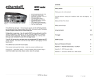
Figure 1-1. Model MS462XX Vector Network Measurement System
Chapter 1
General Information
1-1
SCOPE OF MANUAL
This manual provides general information, installation, and operating
information for the MS4622, MS4623, and MS4624 A, B, C, and D
models Vector Network Measurement System (VNMS). (Throughout
this manual, the terms MS462XX VNMS and MS462XX will be used
interchangeably to refer to the system.) Manual organization is shown
in the table of contents.
1-2
INTRODUCTION
This section provides general information about the MS462X VNMS
system and its precision-component calibration kits.
1-3
SERIAL NUMBER
All Anritsu instruments are assigned a unique six-digit serial
number, such as “940101.” This number is affixed to a decal on the
rear panel of each unit. In any correspondence with Anritsu Customer
Service, please use this number.
1-4
ONLINE MANUALS
Updates to this manual are available at the Anritsu Internet site
(http://www.anritsu.com) as an Adobe Acrobat™ (*.pdf) file. The file
can be viewed using Adobe Acrobat Reader™, a free program that is
available from the Adobe web site. This file is “linked” such that the
viewer can choose a topic to view from the displayed “bookmark” list
and “jump” to the manual page on which the topic resides. The text
can also be word-searched.
RELATED MANUALS
AND LITERATURE
This manual is one of a three-manual set that covers the operation,
programming, and maintenance of the MS462XX. There is also a body
of other literature that provides applications-oriented help in
understanding and using this product. These manuals and literature
are listed in Table 1-1 (following page).
1-5
MS462XX OM
1-3
EXTERNAL
INTERFACES
GENERAL
INFORMATION
Table 1-1. Related Manuals, Literature, and Software for MS462XX
Literature
Part Number
Manuals and User Guides
Literature
Part Number
AutoCal
11410-00258
MS462XX Operation Manual
10410-00203
Software
MS462XX Programming Manual
10410-00204
Scorpion Command Encyclopedia
2300-364
MS462XX Maintenance Manual
10410-00205
Power Tools
2300-218
MS462XX GPIB Quick Reference Guide
10410-00206
LabView Drivers
2300-358
MS462XX Measurement Guide
10410-00213
Exact Uncertainty
2300-361
Application Guide
10410-00214
Mixer Measurement Assistant (NxN)
2300-232
Brochures
Demonstration Kits
Scorpion Brochure
11410-00288
Scorpion Demo Kit
AutoCal Brochure
11410-00189
Allied Equipment Manuals and Literature
Power Meter Brochure
11410-00207
ME7840A Power Amplifier Test System
(PATS) Operation Manual
10410-00224
ME7840A Power Amplifier Test System
(PATS) Brochure
11410-00239
Application Notes
Noise Figure
11410-00210
Noise Figure Accuracy
11410-00227
Intermodulation Distortion
11410-00213
Harmonics
11410-00222
Frequency Translated Group Delay
11410-00236
Global Power Sweep
11410-00243
Multiple Source Control
11410-00244
Reflectometer Measurements-Revisited
11410-00214
Time Domain
11410-00206
Frequency Accuracy
11410-00208
1-6
1-4
SYSTEM DESCRIPTION
SC6287
Article Reprints
Microwaves & RF: PATS Reprint
11410-00241
Microwaves Journal: NF Reprint
RF Design: Mixer Reprint
CDs
Scorpion Literature CD
10920-00040
MS462XX Operation Manual and
MS462XX Programming Manual
10920-00033
The MS462XX Vector Network Measurement System (VNMS)
(Figure 1-1) is a single-instrument system that contains a built-in
source, test set, and analyzer. It is produced in six models that cover a
range 10 MHz to 9 GHz. It provides up to 1601 measurement data
points, non-volatile memory for storing and recalling front panel
setups and measurement and calibration data. It provides an
on-screen display of total operational time and date of last system
calibrations, and the number of power-off cycles since the last
calibration. It supports operation over the IEEE 488.2 General
Purpose Interface Bus (GPIB). It also uses the same GPIB command
set to support operations over an Ethernet.
MS462XX OM
GENERAL
INFORMATION
PRECISION
COMPONENT KITS
NOTES
The MS462XC VNMS- Direct Receiver Access version
cannot make system measurements without an external
test set that couples power into the reference and test
channels, such as the Anritsu MS4782A. This manual will
discuss calibration and system measurements for the
MS462XX assuming the user understands the need for the
external test set for the MS462XC.
For the MS462XC, the a1, a2, b1, b2 connectors on the rear
panel are inputs and normally connected to a MS4782X
Test Set, when used with the ME7840A Power Amplifier
Test System. If a test set is not connected, 50 Ohm terminations must be used with these connectors.
1-7
EXTERNAL INTERFACES
MS462XX OM
In addition to the visible external interfaces¾keyboard, LCD, and
floppy disk drive¾the MS462XX provides the following interfaces:
q
IEEE488.2 GPIB: Connects MS462XX to an external controller
for remote programming. Connections provides support for the
37XXX Series GPIB command set (as applicable to MS462XX
hardware). It also provides partial support for the Hewlett
Packard 8753D command set. This interface is described in the
MS462XX Programming Manual, Part Number: 10410-00204
q
Dedicated GPIB: Connects external peripherals for network measurement system controlled operations (such as, GPIB plotters,
frequency synthesizers, and power meters)
q
Printer: Provides support for the Think Jet, HPQuietJet, HP
DeskJet, HP LaserJet II, III, & IV Series, and some Epson compatible printers with Parallel (Centronics) interfaces. Requires a
DB25 male to Centronics male printer cable, APN: 2225-6
q
External I/O: Provides input/output (I/O) access for Channel 1
through Channel 4 limits, including pass and fail indications. It
is also used for TTL Out and TTL In (for Sequence feature)
q
Ethernet: Provides network control of the MS462XX using the native GPIB command set. This interface is also described in the
MS462XX Programming Manual, Part Number: 10410-00204
q
SCSI Interface
q
VGA Output
q
Serial Port for AutoCal
q
Probe: Provides an interface for a high-frequency probe,
HP85024A
1-5
PRECISION
COMPONENT KITS
1-8
PRECISION COMPONENT
KITS
GENERAL
INFORMATION
Two types of precision-component kits are available: calibration and
verification. Calibration kits contain components used to identify and
separate error sources inherent in microwave test setups. Details of
these kits are described in the following paragraphs.
3750R
The 3750R Calibration Kit (Figure 1-2) contains
Calibration Kit precision 3.5 mm components with characteristics
that are traceable to the NIST. Used primarily by
the metrology laboratory, these components provide
the most dependable means of determining system
accuracy. The kit is available as Option 1 or 3, as described below:
q Option 1: A set of five phase equal
insertables
q Option 3: Includes two additional
terminations required for four-port
calibration. In the case of 3.5 mm or N, a
male and female termination would be
added
Figure 1-2. Model 3750R
Calibration Kit
3751R
The 3751R Calibration Kit (Figure 1-3) contains
Calibration Kit precision GPC-7 components with characteristics
that are traceable to the NIST. Used primarily by
the metrology laboratory, these components provide
the most dependable means of determining system
accuracy. The kit is available as Option 2 or 3, as described below:
q Option 2: A third termination required for
three-port calibrations
q Option 3: Includes two additional
terminations required for four-port
calibration. In the case of 3.5 mm or N, a
male and female termination would be
added
Figure 1-3. Model 3751R
Calibration Kit
1-6
MS462XX OM
GENERAL
INFORMATION
PRECISION
COMPONENT KITS
3753R
The 3753R Calibration Kit (Figure 1-4) contains
Calibration Kit precision Type N components with characteristics
that are traceable to the NIST. Used primarily by
the metrology laboratory, these components provide
the most dependable means of determining system
accuracy. The kit is available as Option 1 or 3, as described below:
q Option 1: A set of five phase equal
insertables
q Option 3: Includes two additional
terminations required for four-port
calibration. In the case of 3.5 mm or N, a
male and female termination would be
added
Figure 1-4. Model 3753R
Calibration Kit
MS462XX OM
1-7
OPTIONS
1-9
1-10
1-8
OPTIONS
PERFORMANCE
SPECIFICATIONS
GENERAL
INFORMATION
The following options are available.
q
Option 1: Rack Mount Kit
q
Option 1A: Rack Mount Kit for use with System Console
q
Option 2: Time (Distance) Domain Measurement Capability
q
Option 3A: For the MS4622B, adds an internal 3 GHz second
source, 3rd test port, and a step attenuator
q
Option 3B: For the MS4623B, adds an internal 6 GHz second
source, 3rd test port, and a step attenuator
q
Option 3C: For the MS4622C, adds an internal 3 GHz second
source, 3rd test port, and a step attenuator
q
Option 3D: For the MS4623C, adds an internal 6 GHz second
source, 3rd test port, and a step attenuator
q
Option 3E: For the MS4624B, adds an internal 9 GHz second
source, 3rd test port, and a step attenuator
q
Option 3F: For the MS4624C, adds an internal 9 GHz second
source, 3rd test port, and a step attenuator
q
Option 4: Noise Figure, 50 MHz to 3 GHz
q
Option 4B: Noise Figure, 50 MHz to 6 GHz
q
Option 5: Frequency Translation Group Delay
q
Option 6: Third Test Port
q
Option 7: Transmission and Reflection Step Attenuator
q
Option 8: Harmonic Measurements
q
Option 10: Internal Control of AutoCal
q
Option 11x: Replacement of Type N (female) connectors with
other connector types (Type N (male), GPC-7, 3.5 mm (male) or
3.5 mm (female)
q
Option 13: Intermodulation Distortion (IMD)
q
Option 24: For the MS462XB and MS462XC, adds processing
upgrades (standard on the MS462XD)
System performance specifications are provided in Appendix C.
MS462XX OM
GENERAL
INFORMATION
1-11
PREVENTIVE
MAINTENANCE
PREVENTIVE
MAINTENANCE
The MS462XX VNMS requires periodic cleaning of the cooling fan
screen to prevent an obstruction that could facilitate overheating.
Additional maintenance that may be required includes replacing a
blown fuse, replacing the CPU backup battery, and replacing the LCD
backlight. This additional maintenance is outlined below:
Fuses
The MS462XX contains three fuses, two internal
and one external. The external, rear-panel-mounted
fuse is rated at 5A, 250V, F (quick acting). It is designed to blow first in the event of an over-current
condition. Of the two internal fuses, one is rated at
6.3A, 250V, F (quick acting), and the other at 15A,
32Vdc (automotive type). Neither of the internal
fuses are replaceable at the field level. They are
mounted within the field-replaceable power supply
module. Internal fuse information is provided for
reference only.
CPU Backup
Battery
The MS462XX CPU module contains a lithium battery that powers the instrument’s hard drive. When
this battery becomes discharged, you may observe
the following:
q Inability to view the contents of the hard
drive
q Inability to save or recall hard drive files
(Error 7172 Hard Disk Read Error)
q GPIB address changes after cycling the
instrument power
q Self test fails and displays a battery failure
message
The life of the CPU battery is dependant on instrument use. For example, the maximum life expectancy of the CPU battery is 2.8 years when the
instrument is stored in an unused state (always
powered off), and 5 years when the instrument is in
continual use (always powered on). Anritsu service
centers recommend a proactive approach to maintaining the CPU battery by replacing it every three
years. Refer this maintenance to a qualified Anritsu
service center.
LCD Backlight The MS462XX LCD display contains a backlight
flourescent lamp that has a rated life span of
50,000-hours. The LCD backlight may need to be replaced after this life span has elapsed. Refer this
maintenance to a qualified Anritsu service center.
MS462XX OM
1-9
CONVENTIONS
1-12
CONVENTIONS
GENEERAL
INFORMATION
Throughout this manual, path names may be used to represent the
keystrokes for a desired action or procedure. The pathname begins
with a front panel key selection, followed by additional front panel or
softkey selections, each separated by a forward slash (/). Front panel
key names and soft keys are presented in the manual as they are on
the system, that is, in initial caps or all uppercase letters as
appropriate. For additional clarity, soft keys are shown in boldface
type. For example, the following pathname representation displays the
system model number, serial number, current software version, and
installed options:
Utility/INSTRUMENT STATE PARAMETERS/SYSTEM
Following the path above, the user would press the Utility front panel
key, followed by the INSTRUMENT STATE PARAMETERS soft
key, then the SYSTEM soft key to display the system information.
Individual steps within a procedure may also be presented as
sequentially numbered steps for clarity. Again, front panel key names
and soft keys are presented in the manual as they are on the system.
For example, the following procedure displays the system model
number, serial number, current software version, and installed
options:
Press Utility then the following soft keys:
INSTRUMENT STATE PARAMETERS
SYSTEM
1-10
MS462XX OM
Chapter 2
Installation
Table of Contents
2-1
INTRODUCTION . . . . . . . . . . . . . . . . . . . . . . . . . . . . . . . . . . . 2-3
2-2
INITIAL INSPECTION . . . . . . . . . . . . . . . . . . . . . . . . . . . . . . . . 2-3
2-3
PREPARATION FOR USE . . . . . . . . . . . . . . . . . . . . . . . . . . . . . . 2-3
2-4
GPIB SETUP AND INTERCONNECTION. . . . . . . . . . . . . . . . . . . . . . 2-4
Interface Connector. . . . . . . . . . . . . . . . . . . . . . . . . . . . . . . . . 2-4
Cable Length Restrictions . . . . . . . . . . . . . . . . . . . . . . . . . . . . . 2-4
2-5
SYSTEM GPIB INTERCONNECTION . . . . . . . . . . . . . . . . . . . . . . . . 2-5
GPIB Interface to an External Plotter. . . . . . . . . . . . . . . . . . . . . . . 2-5
GPIB Addresses . . . . . . . . . . . . . . . . . . . . . . . . . . . . . . . . . . 2-5
2-6
ETHERNET SETUP AND INTERCONNECTION. . . . . . . . . . . . . . . . . . 2-5
2-7
EXTERNAL MONITOR CONNECTOR . . . . . . . . . . . . . . . . . . . . . . . 2-6
2-8
RACK MOUNT INSTALLATION . . . . . . . . . . . . . . . . . . . . . . . . . . . 2-6
2-9
PREPARATION FOR STORAGE AND/OR SHIPMENT. . . . . . . . . . . . . . . 2-7
Preparation for Storage . . . . . . . . . . . . . . . . . . . . . . . . . . . . . . 2-7
Preparation for Shipment . . . . . . . . . . . . . . . . . . . . . . . . . . . . . 2-7
2-10
SERVICE CENTERS . . . . . . . . . . . . . . . . . . . . . . . . . . . . . . . . . 2-9
Chapter 2
Installation
2-1
INTRODUCTION
This chapter provides information for the initial inspection and
preparation for use of the MS462XX Vector Network Measurement
System. Information for interfacing the MS462XX to the IEEE-488
General Purpose Interface Bus and reshipment and storage
information is also included.
2-2
INITIAL INSPECTION
Inspect the shipping container for damage. If the container or
cushioning material is damaged, retain until the contents of the
shipment have been checked against the packing list and the
instrument has been checked for mechanical and electrical operation.
If the MS462XX is damaged mechanically, notify your local sales
representative or Anritsu Customer Service. If either the shipping
container is damaged or the cushioning material shows signs of stress,
notify the carrier as well as Anritsu. Keep the shipping materials for
the carrier’s inspection.
WARNING
Use two or more people to lift and move this equipment, or use an
equipment cart. There is a risk of back injury, if this equipment is
lifted by one person.
2-3
PREPARATION FOR USE
No initial setup is required. After unpacking, the MS462XX is ready
for use. The MS462XX is equipped with automatic line-power sensing,
and will operate with any of the following line voltages: 100V, 120V,
220V, 240V +5%, –10%, 48–63 Hz, 350 VA. The MS462XX is intended
for Installation Category (Overvoltage Category) II.
WARNING
When supplying power to this equipment, always use a three-wire
power cable connected to a three-wire power line outlet. If power is
supplied without grounding the equipment, there is a risk of receiving a severe or fatal electric shock.
MS462XX OM
2-3
GPIB SETUP AND
INTERCONNECTION
2-4
GPIB SETUP AND
INTERCONNECTION
INSTALLATION
All functions of the MS462XX (except power on/off and initialization of
the hard disk) can be controlled remotely by an external
computer/controller via the IEEE-488.2 GPIB. The information in this
section pertains to interface connections and cable requirements for
the rear panel GPIB connector. Refer to the MS462XX Programming
Manual, Anritsu part number 10410-00204, for information about
remote operation of the MS462XX using the GPIB and Ethernet.
The MS462XX GPIB operates with any IBM PC compatible
computer/controller equipped with a National Instruments
GPIB-PCII/IIA interface card and software.
Interface
Connector
Interface between the MS462XX and other devices
on the GPIB is via a standard 24-wire GPIB interface cable. For proper operation, order APN 2100-1,
-2, -4, or -5 (1, 2, 4, or 0.5 meter length) cables
through your local sales representative. This cable
uses a double-sided connector; one connector face is
a plug, the other a receptacle. These double-function
connectors allow parallel connection of two or more
cables to a single instrument connector. The pin assignments for the rear panel GPIB connector are
shown in Figure B-3 located in Appendix B.
Cable Length
Restrictions
The GPIB system can accommodate up to 15 instruments at any one time. To achieve design performance on the bus, proper timing and voltage level
relationships must be maintained. If either the cable length between separate instruments or the accumulated cable length between all instruments is
too long, the data and control lines cannot be driven
properly and the system may fail to perform. Cable
length restrictions are as follows:
q No more than 15 instruments may be
installed on the bus
q Total accumulative cable length in meters
may not exceed two times the number of bus
instruments or 20 meters—whichever is less
NOTE
For low EMI applications, the GPIB cable
should be a fully shielded type with
well-grounded metal-shell connectors. Use
Anritsu Model 2100-series cables.
2-4
MS462XX OM
INSTALLATION
2-5
SYSTEM GPIB
INTERCONNECTION
SYSTEM GPIB
INTERCONNECTION
There are two rear panel GPIB IEEE-488 connectors. The IEEE 488.2
connector is used to interface the MS462XX to an external computer/
controller via a standard GPIB cable. The dedicated GPIB connector is
used to interface to plotters and an external source for multiple source
operation via a standard GPIB cable.
GPIB Interface The MS462XX GPIB interface can be configured to
to an External control a suitable external plotter (refer to
Chapter 6—Data Displays). In this mode of operaPlotter
tion, the GPIB is dedicated to this application and
only the MS462XX and the plotter are connected to
the GPIB. Standard GPIB cables are used to interconnect to the plotter.
GPIB
Addresses
2-6
ETHERNET SETUP AND
INTERCONNECTION
MS462XX OM
The MS462XX leaves the factory with the default
GPIB address set to 6. This address may be changed
using the Utility key and REMOTE INTERFACE/GPIB SETUP soft keys.
The MS462XX can be remotely controlled via a network server and an
Ethernet connection. The MS462XX software supports the TCP/IP
network protocol. The TCP/IP protocol setup requires the following:
q
IP Address: Every computer/electronic device in a TCP/IP network requires an IP address. An IP address has four numbers
(each between 0 and 255) separated by periods. For example:
128.111.122.42 is a valid IP address
q
Subnet Mask: The subnet mask distinguishes the portion of the
IP address that is the network ID from the portion that is the
station ID. The subnet mask 255.255.0.0, when applied to the IP
address given above, would identify the network ID as 128.111
and the station ID as 122.42. All stations in the same Local Area
Network (LAN) should have the same network ID but different
station IDs
q
Default Gateway: A TCP/IP network can have a gateway to
communicate beyond the LAN identified by the network ID. A
gateway is a computer or electronic device that is connected to
two different networks and can move TCP/IP data from one network to the other. A single LAN that is not connected to other
LANs requires a default gateway setting of 0.0.0.0. This (0.0.0.0)
is Scorpion’s default gateway setting. If you have a gateway, then
the default gateway would be set to the appropriate value of your
gateway
q
Ethernet Address: An Ethernet address is a unique 48-bit
value that identifies a network interface card to the rest of the
network. Every network card has a unique ethernet address permanently stored into its memory
2-5
PREPARATION FOR
STORAGE AND/OR SHIPMENT
INSTALLATION
Inappropriate setting of the Default Gateway IP Address will cause
the Scorpion system to appear to be locked up at start up. The
instrument will appear to stop working at the following message:
Application loaded successfully, starting system…
Once the Default Gateway IP Address has been inappropriately set,
the only way to restore the system is to use the debugger loader utility
program on the 2300-246 Boot Utility Diskette and the Hyper
Terminal Utility program (supplied with Microsoft Windows)
connected via the serial port on the rear panel. A null modem cable,
part number 800-441, is also required.
Procedures found in Chapter 3 of the MS462XX Programming Manual,
part number 10410-00204, guide you through the Ethernet setup and
configuration process.
2-7
2-8
EXTERNAL MONITOR
CONNECTOR
The rear panel VGA connector allows the internal display information
of the MS462XX to be connected to an external VGA monitor (either
color or monochrome). The pinout of this 15-pin Type D connector is
shown in Appendix B, Page B-10.
RACK MOUNT
INSTALLATION
To install the Option 1 Rack Mount rails, refer to the procedure below.
Step 1.
Disconnect the line cord and any other attachments from the
instrument.
Step 2.
Carefully place the instrument on a secure and stable work surface.
Step 3.
Using a Phillips screwdriver, remove the two handles or four bumper
assemblies (and tilt bail, if installed) from the front of the unit, and
the four feet at the rear. Save the screws for later use.
NOTES
2-6
q
The green-headed screws are metric threads and must be used
only in the appropriately tapped holes
q
The feet, handles, and bumpers are not reused in this application
Step 4.
Remove the side carrying handle screws and remove the handle.
Step 5.
For Option 1A (System Console), install the two Rack Mount Handles
using the green-headed screws removed earlier (or use the ones from
MS462XX OM
INSTALLATION
PREPARATION FOR
STORAGE AND/OR SHIPMENT
the kit). Orient the handles such that the slotted opening in the
handle mounting plate (Figure 2-1) is toward the bottom of the unit.
Slotted Opening
Figure 2-1. Rack Mount Handle Showing Slotted Opening
Step 6.
For Option 1, install the rack mount assembly to the front and rear
using the green-headed screws removed earlier (or use the ones from
the kit). Orient the assemblies such that the slotted opening in the
handle mounting plate (Figure 2-1) is toward the bottom of the unit.
This completes the installation of the slide assembly.
2-9
PREPARATION FOR
STORAGE AND/OR
SHIPMENT
MS462XX OM
The following paragraphs describe the procedure for preparing the
MS462XX for storage or shipment.
Preparation
for Storage
Preparing the MS462XX for storage consists of
cleaning the unit, packing the inside with moisture-absorbing desiccant crystals, and storing the
unit in a temperature environment that is maintained between –40 and +70 degrees centigrade
(–40 to 156 degrees Fahrenheit).
Preparation
for Shipment
To provide maximum protection against damage in
transit, the MS462XX should be repackaged in the
original shipping container. If this container is no
longer available and the MS462XX is being returned
to Anritsu for repair, advise Anritsu Customer
Service; they will send a new shipping container
free of charge. In the event neither of these two
options is possible, instructions for packaging and
shipment are given on the following page.
2-7
SERVICE
CENTERS
INSTALLATION
Use a Suitable Container
Obtain a corrugated cardboard carton with a
275-pound test strength. This carton should have inside dimensions of no less than six inches larger
than the instrument dimensions to allow for cushioning.
Protect the Instrument
Surround the instrument with polyethylene sheeting to protect the finish.
Cushion the Instrument
Cushion the instrument on all sides by tightly packing dunnage or urethane foam between the carton
and the instrument. Provide at least three inches of
dunnage on all sides.
Seal the Container
Seal the carton by using either shipping tape or an
industrial stapler.
Address the Container
If the instrument is being returned to Anritsu for
service, mark the Anritsu address and your return
address on the carton in one or more prominent
locations. For international customers, use the
address of your local representative (Table 2-1). For
U.S.A. customers, use an Anritsu address shown
below:
Anritsu Company
ATTN: Customer Service
685 Jarvis Drive
Morgan Hill, CA 95037-2809
10 New Maple Avenue
Unit 305
Pine Brook, NJ 07058
1155 E. Collins Blvd.
Richardson, TX 75081
NOTE
Contact Anritsu Call Center at 1-800ANRITSU (1-800-267-4878) for return
instruction prior to shipping the instrument
(for U.S.A. Customers).
2-8
MS462XX OM
INSTALLATION
2-10
SERVICE CENTERS
SERVICE
CENTERS
A list of Anritsu worldwide Service Centers is provided in Table 2-1.
Table 2-1. Anritsu Service Centers
UNITED STATES
FRANCE
JAPAN
ANRITSU COMPANY
490 Jarvis Drive
Morgan Hill, CA 95037-2809
Telephone: (408) 776-8300
1-800-ANRITSU
FAX: 408-776-1744
ANRITSU S.A
9 Avenue du Quebec
Zone de Courtaboeuf
91951 Les Ulis Cedex
Telephone: 016-09-21-550
FAX: 016-44-61-065
ANRITSU CUSTOMER SERVICES LTD.
1800 Onna Atsugi-shi
Kanagawa-Prf. 243 Japan
Telephone: 0462-96-6688
FAX: 0462-25-8379
GERMANY
SINGAPORE
ANRITSU GmbH
Grafenberger Allee 54-56
D-40237 Dusseldorf, Germany
Telephone: 0211-968550
FAX: 0211-9685555
ANRITSU (SINGAPORE) PTE LTD.
10, Hoe Chiang Road
#07-01/02 Keppel Towers
Singapore 089315
Telephone: 6-282-2400
FAX: 6-282-2533
ANRITSU COMPANY
10 New Maple Ave., Unit 305
Pine Brook, NJ 07058
Telephone: (973) 227-8999
1-800-ANRITSU
FAX: 973-575-0092
INDIA
SOUTH AFRICA
ANRITSU COMPANY
1155 E. Collins Blvd
Richardson, TX 75081
Telephone: 1-800-ANRITSU
FAX: 972-671-1877
MEERA AGENCIES PVT. LTD.
23 Community Centre
Zamroodpur, Kailash Colony Extension,
New Delhi, India 110 048
Phone: 011-2-6442700/6442800
FAX : 011-2-644250023
ETECSA
12 Surrey Square Office Park
330 Surrey Avenue
Ferndale, Randburt, 2194
South Africa
Telephone: 011-27-11-787-7200
FAX: 011-27-11-787-0446
AUSTRALIA
ISRAEL
SWEDEN
ANRITSU PTY. LTD.
Unit 3, 170 Foster Road
Mt Waverley, VIC 3149
Australia
Telephone: 03-9558-8177
FAX: 03-9558-8255
TECH-CENT, LTD.
4 Raul Valenberg St
Tel-Aviv 69719
Telephone: (03) 64-78-563
FAX: (03) 64-78-334
ANRITSU AB
Borgafjordsgatan 13
164 40 KISTA, Sweden
Telephone: +46-8-53470700
FAX: +46-8-53470730
BRAZIL
ITALY
TAIWAN
ANRITSU ELECTRONICA LTDA.
Praia de Botafogo, 440, Sala 2401
CEP22250-040, Rio de Janeiro, RJ, Brasil
Telephone: 021-527-6922
FAX: 021-53-71-456
ANRITSU Sp.A
Roma Office
Via E. Vittorini, 129
00144 Roma EUR
Telephone: (06) 50-99-711
FAX: (06) 50-22-425
ANRITSU CO., INC.
7F, No. 316, Section 1
NeiHu Road
Taipei, Taiwan, R.O.C.
Telephone: 886-2-8751-1816
FAX: 886-2-8751-2126
CANADA
KOREA
UNITED KINGDOM
ANRITSU INSTRUMENTS LTD.
700 Silver Seven Road, Suite 120
Kanata, Ontario K2V 1C3
Telephone: (613) 591-2003
FAX: (613) 591-1006
ANRITSU CORPORATION LTD.
8F Hyunjuk Building, 832-41
Yeoksam Dong, Kangnam-Ku
Seoul, South Korea 135-080
Telephone: 02-553-6603
FAX: 02-553-6605
ANRITSU LTD.
200 Capability Green
Luton, Bedfordshire
LU1 3LU, England
Telephone: 015-82-433200
FAX: 015-82-731303
CHINA
ANRITSU ELECTRONICS (SHANGHAI) CO. LTD.
2F, Rm B, 52 Section Factory Building
No. 516 Fu Te Rd (N)
Shanghai 200131 P.R. China
Telephone:21-58680226, 58680227, 58680228
FAX: 21-58680588
MS462XX OM
2-9/2-10
Chapter 3
Network Analyzers,
A Primer
Table of Contents
3-1
INTRODUCTION . . . . . . . . . . . . . . . . . . . . . . . . . . . . . . . . . . . 3-3
3-2
GENERAL DESCRIPTION . .
Source Module or Modules .
Test Set Module . . . . . .
Analyzer Module . . . . . .
3-3
NETWORK ANALYZERS . . . . . . . . . . . . . . . . . . . . . . . . . . . . . . . 3-5
Scalar Analyzer Comparison . . . . . . . . . . . . . . . . . . . . . . . . . . . . 3-5
Vector Network Measurement System Basics . . . . . . . . . . . . . . . . . . 3-6
Network Analyzer Measurements . . . . . . . . . . . . . . . . . . . . . . . . . 3-9
Measurement Error Correction. . . . . . . . . . . . . . . . . . . . . . . . . . 3-11
Summary . . . . . . . . . . . . . . . . . . . . . . . . . . . . . . . . . . . . . 3-12
.
.
.
.
.
.
.
.
.
.
.
.
.
.
.
.
.
.
.
.
.
.
.
.
.
.
.
.
.
.
.
.
.
.
.
.
.
.
.
.
.
.
.
.
.
.
.
.
.
.
.
.
.
.
.
.
.
.
.
.
.
.
.
.
.
.
.
.
.
.
.
.
.
.
.
.
.
.
.
.
.
.
.
.
.
.
.
.
.
.
.
.
.
.
.
.
.
.
.
.
.
.
.
.
.
.
.
.
.
.
.
.
3-3
3-4
3-4
3-5
Chapter 3
Network Analyzers,
A Primer
3-1
3-2
INTRODUCTION
GENERAL DESCRIPTION
This section provides front panel operating and measurement
application information and data. It includes discussions on the
following topics:
q
System description
q
General discussion about network analyzers
q
Basic measurements and how to make measurements
q
Error correction
The Model MS462XX Vector Network Measurement System measures
the magnitude and phase characteristics of networks that include
passives (e.g., diplexers, cables, filters, antennas, SAWS, balanced and
unbalanced); Integrated amplifiers, ICs, LNAs; mixers; power
amplifiers; and tower mounted amplifiers. It compares the incident
signal that leaves the analyzer with either the signal that is
transmitted through the test device or the signal that is reflected from
its input. Figures 3-1 and 3-2 illustrate the types of measurements
that the MS462XX can make.
INCIDENT
TEST
DEVICE
TRANSMITTED
Gain (dB)
Insertion Loss (dB)
Insertion Phase (degrees)
Transmission Coefficients (S12, S21)
Separation of Transmission
Components (Real and Imaginary)
Electrical Length (m)
Electrical Delay (s)
Deviation from Linear Phase (degrees)
Group Delay (s)
Figure 3-1. Transmission Measurements
MS462XX OM
3-3
GENERAL
DESCRIPTION
NETWORK ANALYZERS,
A PRIMER
INCIDENT
TEST
DEVICE
TERMINATION
REFLECTED
Return Loss (dB)
Reflection Coefficients (S11, S22)
Reflection Coefficients vs Distance
(Fourier Transform)
Impedance (R + j X)
SWR
Figure 3-2. Reflection Measurements
The MS462XX is a self-contained, fully integrated measurement
system that includes an optional time domain capability. The system
hardware consists of the following:
q
Analyzer
q
Precision components required for calibration and performance
verification
q
Optional use of Anritsu 67XXB, 68X/ 69X or MG369X series
synthesizers as additional sources
The MS462XX internal system modules perform the following
functions:
Source Module This module provides the stimulus to the device under test (DUT). The frequency range of the source
or Modules
and test set modules establish the frequency range
of the system. The frequency stability of the source
is an important factor in the accuracy (especially
phase accuracy) of the network analyzer. Hence, the
MS462XX always phase locks the source to an internal (or optional external) 10MHz crystal reference.
Test Set
Module
3-4
The test set module routes the stimulus signal to
the DUT and samples the reflected and transmitted
signals. The type of connector used is important, as
is the “Auto Reversing” feature (462XB only). Auto
Reversing means that it applies the stimulus signal
in both the forward and reverse direction. The direction is reversed automatically. This saves you from
having to reverse the test device physically to measure all four scattering parameters (S-parameters).
Frequency conversion occurs in the analyzer.
MS462XX OM
NETWORK ANALYZERS,
A PRIMER
NETWORK
ANALYZERS
Analyzer
Module
3-3
NETWORK ANALYZERS
SCALAR NETWORK ANALYZERS
MICROWAVE
SIGNAL
MICROWAVE
DETECTOR
DETECTOR
OUTPUT
VOLTAGE
DETECTOR OUTPUT VOLTAGE IS PROPORTIONAL
TO SIGNAL AMPLITUDE.
Figure 3-3. Scalar Analyzer
Detection
The analyzer module down-converts, receives, and
interprets the IF signal for phase and magnitude
data. It then displays the results of this analysis on
a color display. This display can show all four
S-parameters simultaneously. In addition to the installed display, you can also view the measurement
results on an external color monitor.
We will begin this discussion with a subject familiar to most Anritsu
customers: scalar network analysis. After showing comparisons, we
will proceed to the fundamentals of network analyzer terminology and
techniques. This discussion serves as an introduction to topics
presented in greater detail later in this section. This discussion will
touch on new concepts that include the following:
q
Reference Delay
q
S-parameters: what they are and how they are displayed
q
Complex Impedance and Smith Charts
Scalar
Analyzer
Comparison
Network Analyzers do everything that scalar analyzers do except display absolute power. In addition,
they add the ability to measure the phase characteristics of microwave devices and allow greater
dynamic range.
If all a Network Analyzer added was the capability
for measuring phase characteristics, its usefulness
would be limited. While phase measurements are
important in themselves, it is the availability of this
phase information that unlocks many new features
for complex measurements. These features include
Smith Charts, Time Domain, and Group Delay.
Phase information also allows greater accuracy
through vector error correction of the measured
signal.
First, let us look at scalar network analyzers
(SNAs). SNAs measure microwave signals by converting them to a DC voltage using a diode detector
(Figure 3-3). This DC voltage is proportional to the
magnitude of the incoming signal. The detection
process, however, ignores any information regarding
the phase of the microwave signal.
In a network analyzer, access is needed to both the
magnitude and phase of a microwave signal. There
are several different ways to perform the
measurement. The method Anritsu employs is to
down-convert the signal to a lower intermediate
MS462XX OM
3-5
NETWORK
ANALYZERS
NETWORK ANALYZERS,
A PRIMER
A NETWORK ANALYZER IS A TUNED RECEIVER
INTERMEDIATE
FREQUENCY (IF)
MICROWAVE
SIGNAL
frequency (IF). This signal can then be measured
directly by a tuned receiver. The tuned receiver
approach gives the system greater dynamic range.
The system is also much less sensitive to interfering
signals, including harmonics.
Vector Network The network measurement system is a tuned receiver (Figure 3-5, left). The microwave signal is
Measurement
System Basics down converted into the passband of the IF.
TUNABLE
LOCAL
OSCILLATOR
• GREATER DYNAMIC RANGE
• LESS SENSIVITY TO INTERFERING SIGNALS
This phase reference can be obtained by splitting off
some of the microwave signal before the measurement (Figure 3-4, below).
Figure 3-5. Network Analyzer is a
Tuned Receiver
REFERENCE
SIGNAL
PHASE
DETECTOR
TEST
SIGNAL
PHASE MEASUREMENT
MICROWAVE
SOURCE
90
SPLITTER
REFERENCE
SIGNAL
DUT
TEST
SIGNAL
Figure 3-4. Splitting the Microwave Signal
TIME
The phase of the microwave signal after it has
passed through the device under test (DUT) is then
compared with the reference signal. The network
analyzer automatically samples the reference signal, so no external hardware is needed.
Figure 3-6. Signals with a
90 Degree Phase Difference
REFERENCE
SIGNAL
PHASE
DETECTOR
TEST
SIGNAL
MICROWAVE
SOURCE
SPLITTER
LONGER
PATH
LENGTH
Figure 3-7. Split Signal where a
Length of Line Replaces the DUT
3-6
Let us consider for a moment that you remove the
DUT and substitute a length of transmission line
(Figure 3-7, left). Note that the path length of the
test signal is longer than that of the reference signal. Now let us see how this affects our measurement.
Assume that we are making a measurement at
1 GHz and that the difference in path-length between the two signals is exactly 1 wavelength. This
means that test signal is lagging the reference signal by 360 degrees (Figure 3-8). We cannot really
tell the difference between one sine wave maxima
and the next (they are all identical), so the network
MS462XX OM
NETWORK ANALYZERS,
A PRIMER
NETWORK
ANALYZERS
analyzer would measure a phase difference of 0 degrees.
REFERENCE
SIGNAL
TEST
SIGNAL
PHASE
DETECTOR
MICROWAVE
SOURCE
SPLITTER
LONGER BY
ONE WAVELENGTH
LENGTH (360 degrees)
Now consider that we make this same measurement
at 1.1 GHz. The frequency is higher by 10 percent so
therefore the wavelength is shorter by 10 percent.
The test signal path length is now 0.1 wavelength
longer than that of the reference signal (Figure 3-9).
This test signal is:
1.1 X 360 = 396 degrees
Figure 3-8. Split Signal where Path
Length Differs by Exactly One Wavelength
REFERENCE
SIGNAL
TEST
SIGNAL
PHASE
DETECTOR
MICROWAVE
SOURCE
SPLITTER
SAME PATH
LENGTH -BUTWAVELENGTH
IS NOW SHORTER
1.1 WAVELENGTHS = 396 degrees
MEASURED PHASE
Figure 3-9. Split Signal where Path
Length is Longer than One Wavelength
This is 36 degrees different from the phase measurement at 1 GHz. The network analyzer will display this phase difference as –36 degrees.
The test signal at 1.1 GHz is delayed by 36 degrees
more than the test signal at 1 GHz.
You can see that if the measurement frequency is
1.2 GHz, we will get a reading of –72 degrees, –108
degrees for 1.3 GHz, etc. (Figure 3-10). There is an
electrical delay between the reference and test signals. For this delay we will use the common industry
term of reference delay. You also may hear it called
phase delay. In older network analyzers you had to
equalize the length of the reference arm with that of
the test arm to make an appropriate measurement
of phase vs. frequency.
To measure phase on a DUT, we want to remove this
phase-change-vs.-frequency-due-to changes in the
electrical length. This will allow us to view the
actual phase characteristics. These characteristics
may be much smaller than the
phase-change-due-to-electrical-length difference.
+180
+90
1.1 1.2 1.3 1.4
0
FREQUENCY,
GHz
-90
-180
Figure 3-10. Electrical Delay
MS462XX OM
3-7
MEASURED PHASE
NETWORK
ANALYZERS
NETWORK ANALYZERS,
A PRIMER
There are two ways of accomplishing this. The most
obvious way is to insert a length of line into the reference signal path to make both paths of equal
length (Figure 3-11, below). With perfect transmission lines and a perfect splitter, we would then measure a constant phase as we change the frequency.
The problem using this approach is that we must
change the line length with each measurement
setup.
+180
+90
0
1.1 1.2 1.3 1.4
FREQUENCY,
GHz
-90
REFERENCE
SIGNAL
SUBTRACT LINEAR
PHASE FROM
MEASURED PHASE
-180
PHASE
DETECTOR
TEST
SIGNAL
MICROWAVE
SOURCE
SPLITTER
Figure 3-12. Phase Difference
Increases Linearly with Frequency
BOTH LINE
LENGTHS
NOW EQUAL
RESULTANT PHASE
Figure 3-11. Split Signal where Paths are of Equal Length
+2
+1
1.3 1.4
1.1
0
-1
1.2
FREQUENCY,
GHz
-2
Figure 3-13. Resultant Phase
with Path Length Compensation
in Place
3-8
Another approach is to handle the path length difference in software. Figure 3-12 (left) displays the
phase-vs.-frequency of a device. This device has different effects on the output phase at different frequencies. Because of these differences, we do not
have a perfectly linear phase response. We can easily detect this phase deviation by compensating for
the linear phase. The size of the phase difference increases linearly with frequency so we can modify the
phase display to eliminate this delay.
The MS462XX offers automatic reference delay
compensation with the push of a button. Figure 3-13
(left) shows the resultant measurement when we
compensate path length. In a system application you
can usually correct for length differences; however,
the residual phase characteristics are critical.
MS462XX OM
NETWORK ANALYZERS,
A PRIMER
NETWORK
ANALYZERS
Network
Analyzer
Measurements
PORT 1
FORWARD
REFLECTION
PORT 2
DUT
REVERSE
REFLECTION
Figure 3-14. Forward and Reverse
Measurements
S21 FORWARD TRANSMISSION
PORT 1
S11 FORWARD
REFLECTION
PORT 2
DUT
S22 REVERSE
REFLECTION
S12 REVERSE TRANSMISSION
Figure 3-15. S-Parameters
PHASE
+180
0
-180
FREQUENCY
Now let us consider measuring the DUT. Consider a
two port device; that is, a device with a connector on
each end. What measurements would be of interest?
First, we could measure the reflection characteristics at either end with the other end terminated into
50 ohms. If we designate one end as the normal
place for the input that gives a reference. We can
then define the reflection characteristics from the
reference end as forward reflection, and those from
the other end as reverse reflection (Figure 3-14).
Second, we can measure the forward and reverse
transmission characteristics. However, instead of
saying “forward,” “reverse,” “reflection,” and “transmission” all the time, we use a shorthand. That is all
that S-parameters are, a shorthand! The “S” stands
for scattering. The second number is the network
analyzer port that the signal is being injected into,
while the first is the network analyzer port that the
signal is leaving. S11, therefore, is the signal being
injected into port 1 relative to the signal leaving
port 1. The four scattering parameters (Figure 3-15):
q
q
q
q
S11 Forward Reflection
S21 Forward Transmission
S22 Reverse Reflection
S12 Reverse Transmission
S-parameters can be displayed in many ways. An
S-parameter consists of a magnitude and a phase.
We can display the magnitude in dB, just like a
scalar network analyzer. We often call this term log
magnitude.
We can display phase as “linear phase” (Figure
3-16). As discussed earlier, we can’t tell the
difference between one cycle and the next. Therefore, after going through 360 degrees we are back to
where we began. We can display the measurement
from –180 to +180 degrees. The –180 to +180 approach is more common. It keeps the display discontinuity removed from the important 0 degree area
used as the phase reference.
Figure 3-16. Linear Phase-withFrequency Waveform
MS462XX OM
3-9
NETWORK
ANALYZERS
NETWORK ANALYZERS,
A PRIMER
POLAR DISPLAY
90
180
0
-90
Figure 3-17. Polar Display
SMITH CHART
INDUCTIVE
50
CAPACITIVE
Figure 3-18. Smith Chart
There are several ways in which all the information
can be displayed on one trace. One method is a polar
display (Figure 3-17). The radial parameter (distance from the center) is magnitude. The rotation
around the circle is phase. We sometimes use polar
displays to view transmission measurements, especially on cascaded devices (devices in series). The
transmission result is the addition of the phase and
log magnitude (dB) information of each device’s polar display.
As we have discussed, the signal reflected from a
DUT has both magnitude and phase. This is because
the impedance of the device has both a resistive and
a reactive term of the form r+jx. We refer to the r as
the real or resistive term, while we call x the imaginary or reactive term. The j, which we sometimes
denote as i, is an imaginary number. It is the square
root of –1. If x is positive, the impedance is inductive, if x is negative the impedance is capacitive.
The size and polarity of the reactive component x is
important in impedance matching. The best match
to a complex impedance is the complex conjugate.
This complex-sounding term simply means an impedance with the same value of r and x, but with x
of opposite polarity. This term is best analyzed using
a Smith Chart (Figure 3-18), which is a plot of r and
x.
To display all the information on a single
S-parameter requires one or two traces, depending
upon the format we want. A very common
requirement is to view forward reflection on a Smith
Chart (one trace) while observing forward transmission in Log Magnitude and Phase (two traces). Let
us see how to accomplish this in the MS462XX.
The MS462XX has four channels. Each channel can
display a complete S-parameter in any format on either one or two traces. All four S-parameters can be
seen simultaneously in any desired format. A total
of eight traces can be viewed at the same time.
While this is a lot of information to digest, the
MS462XX’s large LCD color display makes recognizing and analyzing the data surprisingly easy.
3-10
MS462XX OM
NETWORK ANALYZERS,
A PRIMER
NETWORK
ANALYZERS
Another important parameter we can measure when
phase information is available is group delay. In
linear devices, the phase change through the DUT is
linear-with-frequency. Thus, doubling the frequency
also doubles the phase change. An important measurement, especially for communications system
users, is the rate of change-of-phase-vs.-frequency
(group delay). If the rate of phase-change-vs.-frequency is not constant, the DUT is nonlinear. This
nonlinearity can create distortion in communications systems.
MAGNITUDE AND PHASE OF
EACH ERROR SIGNAL IS MEASURED
MAG
PHASE
THEN THE RESULTANT VECTOR IS
APPLIED MATHEMATICALLY, HENCE
VECTOR ERROR CORRECTION
Figure 3-19. Magnitude and Phase
Measurements
Measurement
Error
Correction
Since we can measure microwave signals in both
magnitude and phase, it is possible to correct for six
major error terms:
q
q
q
q
q
q
Source Test Port Match
Load Test Port Match
Directivity
Isolation
Transmission Frequency Response
Reflection Frequency Response
We can correct for each of these six error terms in
both the forward and reverse directions, hence the
name 12-term error correction. Since 12-term error
correction requires both forward and reverse measurement information, the test set must be reversing. “Reversing” means that it must be able to apply
the measurement signal in either the forward or reverse direction.
To accomplish this error correction, we measure the
magnitude and phase of each error signal
(Figure 3-19). Magnitude and phase information appear as a vector that is mathematically applied to
the stimulus signal. This process is termed vector error correction.
MS462XX OM
3-11
NETWORK
ANALYZERS
NETWORK ANALYZERS,
A PRIMER
Summary
3-12
A network analyzer is similar to a scalar network
analyzer. The major difference it that it adds the capability for measuring phase as well as amplitude.
With phase measurements comes scattering, or
S-parameters, which are a shorthand method for
identifying forward and reverse transmission and
reflection characteristics. The ability to measure
phase introduces two new displays, polar and Smith
Chart. It also adds vector error correction to the
measurement trace. With vector error correction,
errors introduced by the measurement system are
compensated for and measurement uncertainty is
minimized. Phase measurements also add the capability for measuring group delay, which is the rate of
change-of-phase-vs.-frequency (group delay). All in
all, using a network analyzer provides for making a
more complete analysis of your test device.
MS462XX OM
Chapter 4
Front Panel Operation
Table of Contents
4-1
INTRODUCTION . . . . . . . . . . . . . . . . . . . . . . . . . . . . . . . . . . . 4-3
4-2
FRONT PANEL KEY DESCRIPTIONS . . . . . . . . . . . . . . . . . . . . . . . 4-3
4-3
SOFT-KEY MENUS, GENERAL . . . . . . . . . . . . . . . . . . . . . . . . . . . 4-6
4-4
APPL KEY MENUS . . . . . . . . . . . . . . . . . . . . . . . . . . . . . . . . . . 4-7
4-5
MEAS KEY MENUS . . . . . . . . . . . . . . . . . . . . . . . . . . . . . . . . . 4-20
4-6
DISPLAY KEY MENUS . . . . . . . . . . . . . . . . . . . . . . . . . . . . . . . 4-28
4-7
MARKER KEY MENUS . . . . . . . . . . . . . . . . . . . . . . . . . . . . . . . 4-50
4-8
FREQ KEY MENUS . . . . . . . . . . . . . . . . . . . . . . . . . . . . . . . . . 4-62
4-9
SWEEP KEY MENUS . . . . . . . . . . . . . . . . . . . . . . . . . . . . . . . . 4-65
4-10
POWER KEY MENUS . . . . . . . . . . . . . . . . . . . . . . . . . . . . . . . . 4-70
4-11
CONFIG KEY MENUS. . . . . . . . . . . . . . . . . . . . . . . . . . . . . . . . 4-77
4-15
START PRINT KEY MENUS . . . . . . . . . . . . . . . . . . . . . . . . . . . . 4-87
4-16
UTILITY KEY MENUS . . . . . . . . . . . . . . . . . . . . . . . . . . . . . . . 4-88
4-17
HARD COPY KEY MENUS . . . . . . . . . . . . . . . . . . . . . . . . . . . . 4-108
4-18
DEFAULT KEY MENUS . . . . . . . . . . . . . . . . . . . . . . . . . . . . . . 4-115
4-19
SAVE/RECALL KEY MENUS . . . . . . . . . . . . . . . . . . . . . . . . . . . 4-116
4-12
SEQ KEY MENUS . . . . . . . . . . . . . . . . . . . . . . . . . . . . . . . . . 4-121
4-13
CAL KEY MENUS . . . . . . . . . . . . . . . . . . . . . . . . . . . . . . . . . 4-129
4-14
AVG KEY MENUS . . . . . . . . . . . . . . . . . . . . . . . . . . . . . . . . . 4-182
20
MS4623B
18
19
Vector Network Measurement System
10 MHz-6 GHz
Data Entry
7
8
9
G/ns/m
4
5
6
M/m s/cm
1
2
3
k/ms/mm
0
.
-
X1
Enter
Clr
Local
Channels
Enhancement
Appl
Ch 1
Ch 2
Seq
Cal
Ch 3
Ch 4
Avg
Utility
Meas
Display
Stimulus
Port 3
Power
1
2
System
Marker
Freq
Sweep
Print
Hard
Copy
Hold
Power
Config
Default
Save /
Recall
Port 1
Port 2
Keyboard
Probe Power
3
Figure 4-1. MS4623B Network Analyzer Front Panel Controls and Connector
4
5 6
7
8
9
10 11 12 13
14 15 16
17
Chapter 4
Front Panel Operation
4-1
4-2
INTRODUCTION
This chapter describes the front panel keys, controls, menus, and
related GPIB mnemonics. The chapter is organized into an overall
description of the front panel key-groups and detailed descriptions of
individual keys within the key-groups.
FRONT PANEL KEY
DESCRIPTIONS
The following pages provide descriptions of the front panel key-groups
indexed in Figure 4-1.
Index 1
Ground connector:
Index 2
Power: Turns the MS462XX on and off. When on, the operating program runs a self test then recalls the parameters and functions in effect when powered down last.
Index 3
Keyboard connector: Provides for connecting an external
IBM-AT-type keyboard. All alphanumeric field entries can be input
from this keyboard. These inputs include Device ID, Model, Date, Operator Identification, frequencies, filenames, as well as comment-type
entries. The analog knob and keypad input for these entries remains
active. The F1 thru F12 function keys can be used to access certain key
and menu functions. A template is provided and a copy of an actual-size template can be found in a foldout page at the end of this
chapter.
Index 4
Port 3 Connector: Provides an output test connector for the device-under-test (DUT).
Index 5
Soft Keys:
options.
Index 6
Appl Key: Displays the first in a series of menus that provide functions for measurement applications. See page 4-7.
Index 7
Meas Key: Displays the first in a series of menus that let you select
S-parameters. See page 4-20.
Index 8
Port 1 Connector:
der-test (DUT).
Index 9
Hold: Toggles the instrument in and out of the hold modes; or it
triggers a sweep.
Index 10
Marker Key: Displays the first in a series of menus that let you set
and manipulate marker frequencies, powers, times, and distances. See
page 4-50.
Index 11
Display Key: Displays the first in a series of menus that let you
choose graph types, set scales, set reference plane, store trace memory
and manipulate limit lines. See page 4-28.
MS462XX OM
Provides ground connection.
Provides functions that are based on changeable menu
Provides a test connection for the device-un-
4-3
FRONT PANEL
KEY DESCRIPTIONS
Index 12
FRONT PANEL
OPERATION
Stimulus Keys
Freq: Displays the first in a series of menus that provide frequency-sweep control and let you trigger I.F. calibration measurements. See page 4-62.
Sweep: Displays the first in a series of soft-key menus that provide
frequency-sweep control. See page 4-65.
Power: Displays the first in a series of menus that provide RF power
control. See page 4-70.
Config: Displays the first in a series of soft-key menus that provide
control over measurement configuration. See page 4-77.
Index 13
Probe Power Connector: Provides bias voltages of +15 or -12 Vdc
(Figure 4-2) for an external high-impedance probe.
GND
+15
-12
Pin-voltage assignment
when looking into the
connector.
Figure 4-2. Probe Power Connector Pinout
Index 14
Channel Keys
Ch 1: Makes Channel 1 the active channel. The active channel is
the one acted on by the keys in the Display section. Only one channel
can be active at any one time.
Index 15
Ch 2:
Makes Channel 2 the active channel.
Ch 3:
Makes Channel 3 the active channel.
Ch 4:
Makes Channel 4 the active channel.
Enhancement Keys
Seq: Displays a series of sequencing menus that allow you to create,
modify, and store up to seven sequences that can be executed automatically. See page 4-121.
Cal: Calls up the first in a sequence of menus that guide you
through a measurement calibration. See page 4-129.
Avg: Displays a menu that lets you control the Average, Smoothing,
and IF Bandwidth functions. See page 4-182.
Utility: Displays the first in a series of menus that let your perform
network, diskette, auto cal characterization and assurance, trouble
shooting and other utility functions. See page 4-88.
4-4
MS462XX OM
FRONT PANEL
OPERATION
Index 16
FRONT PANEL
KEY DESCRIPTIONS
System Keys
Print: Tells the printers, plotters or disk files to start output based
on the current selections.
Hard Copy: Displays the first in a series of menus that let you define
and perform hard-copy output functions to printers, plotters or disk
files. See page 4-108.
Default: Displays a menu that lets you return the MS462XX front
panel to its default settings. See page 4-115.
NOTE
Use of this key will destroy front panel and calibration
setup data, unless they have been saved to disk.
Save/Recall: Displays the first of several menus that let you save
the current calibration or front panel setup or recall a previously
saved calibration or setup. See page 4-116.
Index 17
Port 2 Connector: Provides an input test connection for the device-under-test (DUT).
Index 18
Data Entry Keys
Rotary Knob: Used to alter measurement values for the active parameter (Start Frequency, Stop Frequency, Offset, etc.). It is also used
to scroll up or down in a sequencing editor box.
Keypad: Provides for entering values for the active parameter. The
active parameter is the one to which the menu cursor is pointing.
G/ns/m: Terminates a value entered on the keypad in the units
shown —that is; gigahertz for frequency, nanoseconds for time, or meters for length.
M/us/cm: Terminates a value entered on the keypad in the units
shown—that is; megahertz for frequency, microseconds for time, or
centimeters for length.
k/ms/mm: Terminates a value entered on the keypad in the units
shown—that is; kilohertz for frequency, milliseconds for time, or millimeters for length.
X1: Terminates a value entered on the keypad in the units
shown—times 1 or unity for power, angle, or dimension less entries.
Clr/Local:
a. Local (Non-GPIB) Mode: (1) The key clears entries not yet terminated by one of the terminator keys above, which allows the previously
displayed values to redisplay. Or (2) the key turns off the displayed
menu and expands the data area to fill the entire screen, if you have
not made any keypad entries needing termination. Or (3) the key terminates any calibration, sequencing, and certain editing functions that
are in progress.
MS462XX OM
4-5
FRONT PANEL
KEY DESCRIPTIONS
FRONT PANEL
OPERATION
b. GPIB Mode: The key returns the instrument to local (front panel)
control, unless the controller has sent a local lockout message (LLO)
over the bus.
4-3
4-6
Index 19
Diskette Drive: Provides for the 3.5-inch, high-density (1.44 MB)
floppy diskette used to store selected front panel setups and calibrations.
Index 20
CRT Display: Displays any or all of the four measurement channels,
plus soft-key menus.
SOFT-KEY MENUS,
GENERAL
The eight soft keys adjacent to the screen provide sets of variable
functions based on other front panel keys, such as Appl, Markers, Freq,
etc. The name of each soft-key menu appears on the MS462XX LCD at
the menu top. The tabulations that appear on the following pages
provide alphabetical listings of each soft-key menu groups, along with
a description and related GPIB mnemonic for each soft-key function.
Menu maps showing the hierarchical structure are provided in
Appendix D.
MS462XX OM
FRONT PANEL
OPERATION
4-4
APPL
KEY MENUS
APPL KEY MENUS
Menu Name
This key provides entry to measurement application functions.
Function
MEASUREMENT TYPE
XXXX
Description
Changes the soft-key display to the
MEASUREMENT TYPE menu.
APPX?
Selects device type to be non-mixer.
APPDEVS
DEVICE TYPE
APPLICATIONS STANDARD
MIXER
GPIB Mnemonic
APPDEVX?
Selects device type to be mixer.
APPDEVM
ENTRY STATE
CURRENT/PREVIOUS
Switches between current and previous
application entry states.
APPENTC; APPENTP
START XXX.XXX mm/cm
Sets the start distance of the display.
ZST; ZST?
STOP XXX.XXX mm/cm
Sets the stop distance of the display
ZSP; ZSP?
CENTER XXX.XXX mm/cm
Sets the center distance of the display.
ZCT; ZCT?
SPAN XXX.XXX mm/cm
Sets the span (Stop - Start) distance of the
display
ZSN; ZSN?
BANDPASS
PHASOR IMPULSE ON/OFF Switches Phasor Impulse processing on or off.
DISTANCE
MORE
Changes the soft-key display to the
DISPLAY SETUP
BANDPASS TIME DOMAIN SETUP2 menu.
TDPI1; TDPI0; TDPIX?
None
HELP ON/OFF
Displays an informational help menu.
HELP1; HELP0; HELPX?
RETURN
Returns to the previous soft-key menu.
None
REL. VELOCITY X.X
Indicates the relative velocity of light, as set by None
the dielectric constant in the SET DIELECTRIC
menu (Display key).
START
XXX.XXX ps/ns
Sets the start time of the display.
ZST; ZST?
STOP
XXX.XXX ps/ns
Sets the stop time of the display.
ZSP; ZSP?
CENTER
XXX.XXX ps/ns
Sets the center time of the display.
ZCT; ZCT?
SPAN
XXX.XXX ps/ns
Sets the span (Stop - Start) time of the display.
ZSN; ZSN?
PHASOR ON/OFF
IMPULSE
Switches Phasor Impulse processing on or off.
TDPI1; TDPI0; TDPIX?
Changes the soft-key display to the
BANDPASS TIME DOMAIN SETUP2 menu.
None
BANDPASS TIME MORE
DOMAIN SETUP
HELP ON/OFF
Displays an informational help screen.
HELP1; HELP0; HELPX?
RETURN
Returns to the previous soft-key menu.
None
MARKER RANGE
Changes the soft-key display to the TIME
MARKER SWEEP or DISTANCE MARKER
SWEEP menu.
None
WINDOW SHAPE
XXXXXXXXX
Changes the soft-key display to the WINDOW
SHAPE SETUP menu.
None
GATE SETUP
Changes the soft-key display to the GATE
SETUP menu.
None
RETURN
Returns to the previous soft-key menu.
None
MS462XX OM
4-7
APPL
KEY MENUS
Menu Name
D.C. TERM
SETUP FOR
LOWPASS
PROCESSING
FRONT PANEL
OPERATION
Function
Description
AUTO EXTRAPOLATE
Sets the D.C. term to a value determined by
extrapolating the data points near the zero
frequency.
DCA; DCX?
LINE
IMPEDANCE
Sets the D.C. term to the characteristic
impedance of the transmission medium (Z0).
DCZ
OPEN
Sets the D.C. term to correspond to an open
circuit.
DCO
SHORT
Sets the D.C. term to correspond to a short
circuit.
DCS
OTHER
XXX.XXX
Sets the D.C. term to the value entered.
DCV
(REFLECTION
COEFFICIENT
X.XXX pU)
Displays the reflection coefficient value.
DCX?
RETURN
Returns to the previous soft-key menu.
None
START MARKER ( )
XX.XXXX cm
Sets the start distance to the value of the
selected marker.
M1S thru M12S
Sets the stop distance to the value of the
selected marker.
M1E thru M12E
Returns the display to the original distance
range that was in effect before the marker
range was selected.
MRR
Returns to the previous soft-key menu.
None
STOP MARKER ( )
XX.XXXXcm
DISTANCE
MARKER SWEEP RESTORE
ORGINAL RANGE
RETURN
SELECT DOMAIN
None
FREQUENCY,
NO TIME GATE
Displays the data in the frequency domain, with FQD; TDX?
no time gate.
FREQUENCY,
WITH TIME GATE
Displays the data in the frequency domain,
after a specific time range has been sampled
by the gate function.
TIME,
LOWPASS
Displays the data in the time (distance) domain, TLP
using true lowpass processing. Data must be
taken using a harmonic series calibration and
sweep.
TIME,
BANDPASS
Displays the data in the time (distance) domain TBP
using bandpass processing. Any data sweep
range using normal calibration can be used.
DISPLAY
TIME/DISTANCE
Toggles between TIME and DISTANCE display TDDIST; TDTIME;
TDDIST?
when TIME LOWPASS or TIME BANDPASS
mode is selected.
SETUP
Changes the soft-key display to the DOMAIN 2 None
menu.
HELP ON/OFF
Displays an informational help screen.
DOMAIN
4-8
GPIB Mnemonic
FGT
HELP1; HELP0; HELPX?
MS462XX OM
FRONT PANEL
OPERATION
Menu Name
DOMAIN2
ENR TABLE
OPERATION
FREQUENCY
TRANSLATION
GROUP DELAY
APPL
KEY MENUS
Function
Description
GPIB Mnemonic
RANGE SETUP
Changes the soft-key display to a DISPLAY
SETUP menu.
None
GATE SETUP
Changes the soft-key display to the GATE
SETUP menu.
None
SELECT GATE
FUNCTION
None
OFF
Switches gate function Off.
GOF
DISPLAY
Switches gate function to Display.
GDS
ON
Switches gate function ON.
GON
HELP ON/OFF
Displays an informational help screen.
HELP1; HELP0; HELPX?
SAVE ENR TABLE
Changes the soft-key display to the SAVE ENR None
TABLE menu
LOAD ENR TABLE
Changes the soft-key display to the LOAD ENR None
TABLE menu
EXTERNAL EXTENSION/
TABLE ON/OFF
Turns the external extension table on or off
NFXENR0; NFXSWR1;
NFXENRX?
DISPLAY ENR TABLE
Changes the soft-key display to the DISPLAY
ENR TABLE menu.
None
RETURN
Returns to the previous soft-key menu.
None
Turns ABSOLUTE PHASE mode on or off.
ABSOLUTE
PHASE
ON/OFF
(PHASE SHIFT
DOES NOT APPLY
IN ABS PHASE)
ABSPHASE0;
ABSPHASE1;
ABSPHASE?
HELP ON/OFF
Displays an informational help screen.
HELP1; HELP0; HELPX?
CHANGE
APPLICATION
SETUP
Changes the soft-key display to the top-level
APPLICATIONS menu.
None
START
XXX.XXX ns
Sets the start time of the gate.
GST; GST?
STOP
XXX.XXX ns
Sets the stop time of the gate.
GSP; GSP?
CENTER
XXX.XXX ns
Sets the center time of the gate.
GCT; GCT?
SPAN
XXX.XXX ns
Sets the span (Stop - Start) of the gate. It also
provides for an anti-gate if a negative value is
entered. Refer to Chapter 8, paragraphs 8-6
and 8-7 for additional information.
GSN; GSN?
GATE SHAPE
XXXXXXXXX
Changes the soft-key display to the GATE
SHAPE SETUP menu.
GSX?
GATE ON/OFF/DISP
Selects the gate display mode.
GOF; GON; GDS; GOF?
RANGE SETUP
Changes the soft-key display to the LOWPASS None
DISTANCE DISPLAY SETUP, LOWPASS TIME
DOMAIN SETUP, BANDPASS DISTANCE
DISPLAY SETUP, or BANDPASS TIME
DOMAIN SETUP menu.
RETURN
Returns to the previous soft-key menu.
GATE SETUP
MS462XX OM
None
4-9
APPL
KEY MENUS
Menu Name
HARMONIC
FRONT PANEL
OPERATION
Function
Description
SWEEP MODE
SOURCE/CW RCVR
Sweeps the source frequency or receiver
frequency.
APPSWPC; APPSWPS;
APPSWPX?
PORT 1,2/1,3
Selects Port 1, Port 2, or Port 3 as the second
port.
HARP12; HARP13;
HARPX?
HARMONIC SETUP
Changes the soft-key display to the
HARMONIC SETUP menu.
None
HELP ON/OFF
Displays an informational help screen.
HELP1; HELP0; HELPX?
CHANGE APPLICATION
SETUP
Changes the soft-key display to the top-level
APPLICATIONS menu.
None
HARMONIC (1-9)
Selects the harmonic to be measured.
HAR1 thru HAR9;
HARX?
DISPLAY OUTPUT
RELATIVE TO:
HARMONIC
SETUP
None
SOURCE HARMONIC
Selects display of harmonic output power
relative to source harmonic power.
HARDSH; HARDX?
SOURCE
FUNDAMENTAL
Selects display of harmonic output power
relative to source fundamental power.
HARDSF; HARDX?
OUTPUT
FUNDAMENTAL
Selects display of harmonic output power
relative to output fundamental power.
HARDOF; HARDX?
HELP ON/OFF
Displays an informational help screen.
HELP1; HELP0; HELPX?
RETURN
Returns to the previous soft-key menu.
None
THIRD ORDER
INTERMODULATION
INTERCEPT/PRODUCT
None
Selects Intercept/Product TOI display.
MEASURE RELATIVE TO:
IMD DISPLAY
SELECTION
4-10
GPIB Mnemonic
IMDDI; IMDDP; IMDDX?
None
TONE1
(UPPER PRODUCT)
Selects measurement relative to Tone 1.
This menu item only displays in the non-mixer
mode.
IMDRT1; IMDRTX?
TONE2
(LOWER PRODUCT)
Selects measurement relative to Tone 2.
This menu item only displays in the non-mixer
mode.
IMDRT2; IMDRTX?
MEAS REFERENCE
INPUT/OUTPUT
Toggles measurement reference between input IMDMRI; IMDMRO;
and output.
IMDMRX?
HELP ON/OFF
Displays an informational help screen.
HELP1; HELP0; HELPX?
RETURN
Returns to the previous soft-key menu.
None
MS462XX OM
FRONT PANEL
OPERATION
Menu Name
IMD SOURCE
SELECTION
INTERMODULATION
DISTORTION
LOAD ENR
TABLE
APPL
KEY MENUS
Function
Description
GPIB Mnemonic
SELECTOR MODE
DEFINE/APPLY
Switches between DEFINE and APPLY setup
modes. The parameter changes selected
below are not applied to the hardware while in
DEFINE mode.
IMDSSMD; IMDSSMA;
IMDSSMX?
TONE 1 IS SOURCE
(1-4)X
Selects Tone 1 source.
IMDT1S1-IMDT1S4;
IMDT1SX?
TONE 2 IS SOURCE
(1-4)X
Selects Tone 2 source.
IMDT2S1-IMDT2S4
LO IS SOURCE
(2-4)X
Selects local oscillator source.
(Mixer mode only)
APPLORS2-APPLORS4;
APPLORSX?
SOURCE 2 USING
PORT3/PORT4
Selects source 2 to drive port 3 or port 4
This menu item only displays in 4-port models.
MIXP3; MIXP4;
MIXPORT?
HELP ON/OFF
Displays an informational help screen.
HELP1; HELP0; HELPX?
RETURN
Returns to the previous soft-key menu.
None
SWEEP MODE
SOURCE/CW RCVR
Sweeps either the source frequency or receiver APPSWPC; APPSWPS;
frequency.
APPSWPX?
DISPLAY SELECTION XXX
Changes the soft-key display to the IMD
DISPLAY SELECTION menu.
IMDDX?
TONE 2 OFFSET
+/-XX.XXXXXXXX GHz
Sets offset of Tone 2 from Tone 1.
IMDT2OFF; IMDT2OFF?
SOURCE SELECTION
Changes the soft-key display to the TOI
SOURCE SELECTION menu.
None
IMD ORDER
3/5/7/9
Selects intermodulation products.
IMD3; IMD5; IMD7;
IMD9; IMDOX?
HELP ON/OFF
Displays an informational help screen.
HELP1; HELP0; HELPX?
CHANGE APPLICATION
SETUP
Changes the soft-key display to the top-level
APPLICATIONS menu.
None
FROM HARD DISK
Changes the soft-key display to the SELECT
FILE TO READ.
None
VENDOR ENR TABLE
Load ENR table of Noise Source
NFLENRH
INTERNAL ENR
EXTENSION TABLE
Load ENR extension between INT Noise Src
and Port1
None
EXTERNAL ENR
EXTENSION TABLE
Load ENR extension between Port 1 and DUT
NFLNFXH
FROM FLOPPY DISK
Changes the soft-key display to the SELECT
FILE TO READ.
None
VENDOR ENR TABLE
Load ENR table of Noise Source
NFLENR
INTERNAL ENR
EXTENSION TABLE
Load ENR extension between INT Noise Src
and Port1
None
EXTERNAL ENR
EXTENSION TABLE
Load ENR extension between Port 1 and DUT
NFLNFX
RETURN
Returns to the previous soft-key menu.
None
MS462XX OM
4-11
APPL
KEY MENUS
Menu Name
FRONT PANEL
OPERATION
Function
GPIB Mnemonic
START
XXX.XXX mm
Sets the start distance of the display.
GST; GST?
STOP
XXX.XXX mm
Sets the stop distance of the display.
GSP; GSP?
CENTER
XXX.XXX mm
Sets the center distance of the display.
GCT; GCT?
Sets the span (Stop - Start) distance of the
display.
GSN; GSN?
SPAN
LOWPASS
XXX.XXX mm
DISTANCE
RESPONSE
DISPLAY SETUP
IMPULSE/STEP
Switches between Impulse and Step response. LPI; LPS; LPSPX?
MORE
Changes the soft-key display to the LOW PASS None
TIME DOMAIN SETUP2 menu.
RETURN
Returns to the previous soft-key menu.
RELATIVE VELOCITY
X.X
Indicates the relative velocity of light, as set by VELO?
the dielectric constant in the SET DIELECTRIC
menu (Display key).
START
XXX.XXX ps
Sets the sweep start time.
GST; GST?
STOP
XXX.XXX ps
Sets the sweep stop time.
GSP; GSP?
Sets the sweep center time.
GCT; GCT?
CENTER
LOWPASS TIME XXX.XXX ps
DOMAIN SETUP
RESPONSE
IMPULSE/STEP
MORE
None
Switches between Impulse and Step response. LPI; LPS; LPSX?
Changes the soft-key display to the LOW PASS None
TIME DOMAIN SETUP2 menu.
RETURN
Returns to the previous soft-key menu.
None
MARKER RANGE
Changes the soft-key display to the TIME
MARKER SWEEP menu.
None
WINDOWS SHAPE
XXXXXXXXXXXX
Changes the soft-key display to the WINDOW
SHAPE SETUP menu.
None
Changes the soft-key display to the GATE
SETUP menu.
None
LOWPASS TIME GATE SETUP
DOMAIN SETUP2
D.C. TERM
XXXX
XXXXXXXX
RETURN
4-12
Description
Changes the soft-key display to the D.C. TERM None
SETUP FOR LOWPASS PROCESSING menu.
Returns to the previous soft-key menu.
None
MS462XX OM
FRONT PANEL
OPERATION
Menu Name
APPL
KEY MENUS
Function
GPIB Mnemonic
TRANSMISSION AND
REFLECTION
Changes the soft-key display to the
TRANSMISSION AND REFLECTION menu or
to the MIXER TRANSMISSION AND
REFLECTION menu, if MIXER is the
measurement type.
APPTR
NOISE FIGURE
Changes the soft-key display to the NOISE
FIGURE menu or to MIXER NOISE FIGURE
menu, if MIXER is the measurement type.
APPNF
Changes the soft-key display to the
HARMONIC menu.
APPHAR
IMD
Changes the soft-key display to the
INTERMODULATION DISTORTION menu or
to MIXER INTERMODULATION DISTORTION
menu, if MIXER is the measurement type.
APPIMD
FREQUENCY
TRANSLATION GROUP
DELAY
Changes the soft-key display to the FREQ
TRANS GRP DLY
APPFTGD
LO/RECEIVER SETUP
Changes the soft-key display to the MIXER
LO/RECEIVER SETUP menu.
MEASUREMENT
HARMONIC
TYPE
(NON-MIXER ONLY)
MIXER
FREQUENCY
TRANSLATION
GROUP DELAY
Description
None
Toggles the ABSOLUTE PHASE mode on or
ABSOLUTE
PHASE
ON/OFF off.
(PHASE SHIFT
DOES NOT APPLY
IN ABS PHASE)
ABSPHASE0;
ABSPHASE1;
ABSPHASE?
HELP ON/OFF
Displays an informational help screen.
HELP1; HELP0; HELPX?
CHANGE
APPLICATION
SETUP
Changes the soft-key display to the top-level
APPLICATIONS menu.
None
SWEEP MODE
SOURCE/CW RCVR
Selects between sweeping the source
frequency or receiver frequency.
APPSWPC; APPSWPS;
APPSWPX?
DISPLAY SELECTOR XXX
Changes the soft-key display to the IMD
DISPLAY SELECTION menu.
None
TONE 2 OFFSET
+/1XX.XXXXXXXX GHz
Sets offset of Tone 2 from Tone 1.
IMDT2OFF; IMDT2OFF?
LO RECEIVER SETUP
Changes the soft-key display to the MIXER
LO/RECEIVER SETUP menu.
None
MIXER INTERMODULATION
DISTORTION
This menu selelction is not allowed in multiple
source mode.
SOURCE SELECTION
Changes the soft-key display to the IMD
SOURCE SELECTION menu.
None
IMD ORDER
3/5/7/9
Selects intermodulation products.
IMD3; IMD5; IMD7;
IMD9; IMDOX?
HELP ON/OFF
Displays an informational help screen.
HELP1; HELP0; HELPX?
CHANGE APPLICATION
SETUP
Changes the soft-key display to the top-level
APPLICATIONS menu.
None
MS462XX OM
4-13
APPL
KEY MENUS
Menu Name
MIXER
LO/RECEIVER
SETUP
FRONT PANEL
OPERATION
Function
Description
GPIB Mnemonic
LO IS SOURCE
(2 - 4) X
Selects the LO source.
APPLORS2-APPLORS4;
APPLORSX?
LO OFFSET FROM RF
+/- XXX.XXXXXXXX GHz
Sets the offset of LO from RF frequency, which
is set in the FREQUENCY menu.
APPLOROFF;
APPLOROFF?
LO CW ON/OFF
MODE
Toggles the LO CW mode on or off. If the LO
MODE is on, the LO OFFSET is not displayed.
APPLORCW1;
APPLORCW0;
APPLORCWX?
LO CW FREQUENCY
XXX.XXXXXXXX GHz
Sets the LO CW frequency. If the LO CW
MODE is off, the LO CW FREQUENCY is not
displayed.
APPLORCWF;
APPLORCWF?
RCVR CONVERSION
XXXX
Changes the soft-key display to the SELECT
RECEIVER CONVERSION menu.
None
SOURCE 2 USING PORT
3/PORT 4
Selects source 2 to drive port 3 or port 4
MIXP3; MIXP4;
MIXPORT?
This menu item is only displayed in 4-port
models.
MIXER NOISE
FIGURE
HELP ON/OFF
Displays an informational help screen.
HELP1; HELP0; HELPX?
RETURN
Returns to the previous soft-key menu.
None
DUT BANDWIDTH
NARROW/WIDE
Toggles between narrow and wide bandwidth.
NFDBWW; NFDBWN;
NFDBWX?
NOISE FIGURE SETUP
Changes the soft-key display to the NOISE
FIGURE SETUP menu.
None
DISPLAY SELECTION
Changes the soft-key display to the NOISE
FIGURE DISPLAY SELECTION menu.
None
LO/RECEIVER SETUP
Changes the soft-key display to the MIXER
LO/RECEIVER SETUP menu.
None
INSERT LOSS
Enable to account for loss before or after DUT
None
BEFORE DUT
XXXXXX dB
Sets the insertion loss before the DUT in NF
meas.
NFLB; NFLB?
AFTER DUT
XXXXXX dB
Sets the insertion loss after the DUT in NF
meas.
NFLA; NFLA?
HELP ON/OFF
Displays an informational help screen.
HELP1; HELP0; HELPX?
CHANGE APPLICATION
SETUP
Changes the soft-key display to the top-level
APPLICATIONS menu.
None
DOMAIN
Changes the soft-key display to the DOMAIN
menu.
None
Changes the soft-key display to the
LO/RECEIVER SETUP menu.
None
Displays an informational help screen.
HELP1; HELP0; HELPX?
Changes the soft-key display to the top-level
APPLICATIONS menu.
None
LO/RECEIVER SETUP
MIXER
TRANSMISSION
HELP ON/OFF
AND
REFLECTION CHANGE
APPLICATION
SETUP
4-14
MS462XX OM
FRONT PANEL
OPERATION
Menu Name
APPL
KEY MENUS
Function
Description
TEST AUT
Changes the soft-key display to the MULTIPLE
FREQUENCY GAIN COMPRESSION2 menu.
None
TEXT DATA
TO HARD DISK
Changes the soft-key display to the SELECT
FILE TO OVERWRITE menu.
None
TEXT DATA
TO FLOPPY DISK
Changes the soft-key display to the SELECT
FILE TO OVERWRITE menu.
None
Toggles the FIXED SCALE mode on or off.
GCFSON; GCFSOFF;
GCFS?
Enter the Y start power level for multiple
frequency gain compression.
GCYST; GCYST?
Y STOP
XX.XX DBM
Enter the Y stop power level for multiple
frequency gain compression.
GCYSP; GCYSP?
RETURN TO T/R MODE
Changes the soft-key display to the
TRANSMISSION AND REFLECTION menu.
UNDOGC
RETURN
Returns to the previous soft-key menu.
None
TESTING AUT
Changes the soft-key display to the MULTIPLE
FREQUENCY GAIN COMPRESSION2 menu.
None
Aborts Multiple Frequency Gain Compression
testing.
None
DUT BANDWIDTH
NARROW/WIDE
Toggles between narrow and wide bandwidth.
NFDBWN; NFDBWW;
NFDBWX?
NOISE FIGURE SETUP
Changes the soft-key display to the NOISE
FIGURE SETUP menu.
None
DISPLAY SELECTION
Changes the soft-key display to the NOISE
FIGURE DISPLAY SELECTION menu.
None
INSERT LOSS BEFORE
DUT XXXXXX dB
Selects the insertion loss before the DUT
NFLB; NFLB?
MULTIPLE
FIXED SCALE
FREQUENCY
GAIN
Y START
COMPRESSION
XX.XX DBM
ON/OFF
MULTIPLE
FREQUENCY
GAIN
ABORT
COMPRESSION2
NOISE FIGURE
NOISE FIGURE
DISPLAY
SELECTION
GPIB Mnemonic
AFTER DUT XXXXXX dB Selects the insertion loss after the DUT
NFLA; NFLA?
HELP ON/OFF
Displays an informational help screen.
HELP1; HELP0; HELPX?
CHANGE APPLICATION
SETUP
Changes the soft-key display to the top-level
APPLICATIONS menu.
None
NOISE FIGURE
Selects Noise Figure for data display.
NFDNF; NFDX?
INSERTION GAIN
Selects Insertion Gain Noise Figure for data
display.
NFDIG; NFDX?
AVAILABLE GAIN
Selects Available Gain Noise Figure for data
display.
NFDAG; NFDX?
Y FACTOR
Selects Y Factor Noise Figure for data display.
NFDYF; NFDX?
EQUIVALENT NOISE
TEMPERATURE
Selects equivalent noise temperature for data
display.
NFDENT; NFDX?
HELP ON/OFF
Displays an informational help screen.
HELP1; HELP0; HELPX?
RETURN
Returns to the previous soft-key menu.
None
MS462XX OM
4-15
APPL
KEY MENUS
Menu Name
NOISE FIGURE
SETUP
FRONT PANEL
OPERATION
Function
Description
GPIB Mnemonic
NOISE SOURCE
INTERNAL/EXTERNAL
Toggles noise source between Internal and
External.
NFSRCI; SFSRCE;
NFSRCE; NFSRCX?
COLD TEMPERATURE
XXX.XXX K
Selects Noise Figure Cold Temperature.
NFCT; NFCT?
WIDEBAND BW CORR
FREQ
XXXXXXXX MHz
Displays wideband correction frequency.
NFBW; NFBW?
WIDEBAND BW CORR
MODE ON/OFF
This menu item only displays if wideband mode
is on.
Turns wideband correction mode feature
on/off.
NFBWC1; NFBWC0;
NFBWCX?
This menu item only displays if wideband mode
is on.
ENR TABLE OPERATION
Changes the soft-key display to the ENR
TABLE OPERATION menu
SSB CORRECTION
ON/OFF
Toggles SSB (single sideband) correction on or NFSSBC1; NFSSBC0;
off.
NFSSBCX?
HELP ON/OFF
Displays an informational help screen.
HELP1; HELP0; HELPX?
RETURN
Returns to the previous soft-key menu.
None
TO HARD DISK
Saves Vendor ENR table into the Floppy Disk
None
VENDOR ENR TABLE
Saves Vendor ENR table into the Hard Disk
None
INTERNAL ENR
EXTENSION TABLE
Saves the Int ENR table into the Hard Disk
None
EXTERNAL ENR
EXTENSION TABLE
Saves the Ext ENR table into the Hard Disk
None
Saves the Int ENR table into the Floppy Disk
None
SAVE ENR TABLE TO FLOPPY DISK
VENDOR ENR TABLE
SELECT
RECEIVER
CONVERSION
4-16
None
Saves Vendor ENR table into the Hard Disk
None
INTERNAL ENR
EXTENSION TABLE
Saves the Int ENR table into the Hard Disk
None
EXTERNAL ENR
EXTENSION TABLE
Saves the Ext ENR table into the Hard Disk
None
RETURN
Returns to the previous soft-key menu.
None
UP
Selects mixer conversion directions and hence
the receiver (IF) frequency. Up implies
IF=RF+LO. Down implies IF=RF-LO.
APPLORRCU;
APPLORRCX?
DOWN
Selects mixer conversion directions and hence
the receiver (IF) frequency. Up implies
IF=RF+LO. Down implies IF=RF-LO.
APPLORRCD;
APPLORRCX?
NONE
Selects mixer conversion directions and hence
the receiver (IF) frequency. Up implies
IF=RF+LO. Down implies IF=RF-LO.
APPLORRCN;
APPLORRCX?
RETURN
Returns to the previous soft-key menu.
None
MS462XX OM
FRONT PANEL
OPERATION
Menu Name
APPL
KEY MENUS
Function
NOMINAL OFFSET XXX dB
Description
GPIB Mnemonic
Sets nominal offset.
NOFST; NOFST?
Sets gain compression point.
GCMP; GCMP?
Changes the soft-key display to the TEST
SIGNALS menu.
SFGCT
Displays an informational help screen.
HELP1; HELP0; HELPX?
RETURN TO T/R MODE
Changes the soft-key display to the
TRANSMISSION AND REFLECTION menu.
UNDOGC
SET FREQUENCIES
Changes the soft-key display to the SWEPT
POWER GAIN COMPRESSION2 menu.
IFV
SET ATTENUATION
Changes the soft-key display to the SWEPT
POWER GAIN COMPRESSION4 menu.
None
SET POWER
Changes the soft-key display to the SWEPT
POWER GAIN COMPRESSION3 menu.
None
GAIN COMPRESSION
POINT (XXX.XX dB)
SWEPT
TEST AUT
FREQUENCY
GAIN
COMPRESSION HELP ON/OFF
SWEPT POWER SWEPT NORMALIZATION
GAIN
OF S21 ON/OFF
COMPRESSION TEST AUT
Changes the soft-key display to the SWEPT
POWER SETUP menu.
Changes the soft-key display to the SWEPT
POWER SETUP menu.
SPGCT
MULTIPLE FREQ GAIN
COMPRESSION
Changes the soft-key display to the MULTIPLE
FREQUENCY GAIN COMPRESSION menu.
MFGCT
RETURN TO T/R MODE
Changes the soft-key display to the
TRANSMISSION AND REFLECTION menu.
UNDOGC
HELP ON/OFF
Displays an informational help screen.
HELP1; HELP0; HELPX?
NEXT FREQUENCY
XXX.XXXXXXX GHz
Sets the next frequency to be imported in the
frequency list.
DFQ; DFQ?
INSERT NEXT
FREQUENCY
Inserts the NEXT FREQUENCY into the
frequency list.
IFV
Selects the frequency number to be cleared.
IFV
Clears the selected frequency.
IFV
SWEPT POWER FREQUENCY NUMBER TO
GAIN
BE CLEARED XX
COMPRESSION 2
CLEAR SELECTED
FREQUENCY
CLEAR ALL FREQUENCIES Clears all frequencies in the list.
IFV
RETURN
Returns to the previous soft-key menu.
None
P START XX.XX dBm
Sets the sweep start frequency.
PSTRT; PSTRT?
P STOP XX.XX dBm
Sets the sweep stop frequency.
PSTOP; PSTOP?
STEP SIZE XX.XX dB
Sets the power sweep step size.
PSTEP; PSTEP?
P SET XX.XX dBm
Enter target power for gain compression
receiver calibration.
PSET; PSET?
Sets gain compression point.
GCMP; GCMP?
SWEPT POWER
GAIN
COMPRESSION3 GAIN COMPRESSION
POINT (MAX REF)
XX.XX dBm
NOMINAL OFFSET XXX dB
Sets nominal offset.
NOFST; NOFST?
RETURN
Returns to the previous soft-key menu.
None
SWEPT POWER PORT 1 ATTN 0*10dB (0-70) Sets Port 1 attenuator.
PORT 3 ATTN 0*10dB (0-70) Sets Port 3 attenuator.
GAIN
COMPRESSION4 RETURN
Returns to the previous soft-key menu.
MS462XX OM
SA1; SA1?
SA3; SA3?
None
4-17
APPL
KEY MENUS
Menu Name
FRONT PANEL
OPERATION
Function
SWEPT POWER
FREQUENCY
XXX.XXXXXX GHz
Description
Sets the power sweep frequency.
GPIB Mnemonic
PSF; PSF?
P START XX.XX dBm
Displays the sweep start power.
PSTRT?
P STOP XX.XX dBm
Displays the sweep stop power.
PSTOP?
Displays the power sweep step size.
PSTEP?
Toggles the power sweep on or off.
PSWP1; PSWP0;
PSWPX?
MULTIPLE FREQ GAIN
COMPRESSION
Changes the soft-key display to the MULTIPLE
FREQUENCY GAIN COMPRESSION menu.
None
RETURN TO T/R MODE
Changes the soft-key display to the
TRANSMISSION AND REFLECTION menu.
UNDOGC
RETURN
Returns to the previous soft-key menu.
None
SOURCE 1 POWER XX.XX
dBm (XX TO YY)
Sets the Source 1 power level.
PWR; PWR?
PORT 1 ATTN 0*10 dB
(0-70)
Sets Port 1 attenuation in 10 dB steps.
SA1
PORT 1 POWER XX.XX
dBm
Displays resulting output power level of Port 1.
P1P?
SOURCE 2 POWER XX.XX
dBm
Sets the Source 2 power level.
PW2
PORT 3 ATTN 0*10 dB
(0-70)
Sets Port 3 attenuation in 10 dB steps.
SA3
PORT 3 POWER XX.XX
dBm
Displays resulting output power level of Port 3.
P3P?
RETURN TO T/R MODE
Changes the soft-key display to the top-level
APPLICATIONS menu.
UNDOGC
START MARKER ( )
XXX.XXX ns
Sets the start time to the value of the selected
marker.
M1S thru M12S
STOP MARKER ( )
XXX.XXX ns
Sets the stop time to the value of the selected
marker.
M1E thru M12E
RESTORE
ORIGINAL RANGE
Returns the display to the original time range
that was in effect before the marker range was
selected.
MRR
RETURN
Returns to the previous soft-key menu.
None
DOMAIN
Changes the soft-key display to the DOMAIN
menu.
SWEPT POWER GAIN
TRANSMISSION COMPRESSION
SWEPT FREQUENCY GAIN
AND
REFLECTION COMPRESSION
HELP ON/OFF
Changes the soft-key display to the SWEPT
POWER GAIN COMPRESSION menu.
APPGCP
Changes the soft-key display to the SWEPT
FREQUENCY GAIN COMPRESSION menu.
APPGCF
Displays an informational help screen.
HELP1; HELP0; HELPX?
Changes the soft-key display to the top-level
APPLICATIONS menu.
None
STEP SIZE XX.XX dB
SWEPT POWER
POWER SWEEP ON/OFF
SETUP
TEST SIGNALS
TIME MARKER
SWEEP
CHANGE APPLICATION
SETUP
4-18
MS462XX OM
FRONT PANEL
OPERATION
Menu Name
APPL
KEY MENUS
Function
Description
GPIB Mnemonic
RECTANGULAR
Selects a Rectangular (one-term) shape.
NOMINAL
Selects a two-term Hamming shape.
WNM; GNM
Selects a three-term Blackman-Harris shape.
WLS; GLS
Selects a four-term Blackman-Harris shape.
WMS; GMS
HELP ON/OFF
Displays an informational help screen.
HELP1; HELP0; HELPX?
RETURN
Returns to the previous soft-key menu.
None
WINDOW/GATE LOW SIDELOBE
SHAPE SETUP MIN SIDELOBE
MS462XX OM
WRT; GRT
4-19
MEAS
KEY MENUS
4-5
FRONT PANEL
OPERATION
MEAS KEY MENUS
Menu Name
SELECT
BALANCED
PORT PAIR
Function
Description
GPIB Mnemonic
(1:2)/(2:1)
Selects Ports 1:2 or 2:1 as the balanced port pair for MM1P12; MM1P21;
the active channel.
MM1P?
(1:3)/(3:1)
Selects Ports 1:3 or 3:1 as the balanced port pair for MM1P13; MM1P31;
the active channel.
MM1P?
(2:3)/(3:2)
Selects Ports 2:3 or 3:2 as the balanced port pair for MM1P23; MM1P32;
the active channel.
MM1P?
Changes the soft-key display to the SELECT
SINGLE ENDED PORT (3 PORT MODELS WITH
OPTION 24) menu.
None
RETURN
Changes the soft-key display to the previous
SELECT MIXED MODE S-PARAMETER menu.
None
(1:2)/(2:1)
Selects Ports 1:2 or 2:1 as the balanced port pair for MM1P12; MM1P21;
the active channel.
MM1P?
(1:3)/(3:1)
Selects Ports 1:3 or 3:1 as the balanced port pair for MM1P13; MM1P31;
the active channel.
MM1P?
(2:3)/(3:2)
Selects Ports 2:3 or 3:2 as the balanced port pair for MM1P23; MM1P32;
the active channel.
MM1P?
(1:4)/(4:1)
Selects Ports 1:4 or 4:1 as the balanced port pair for MM1P14; MM1P41;
the active channel.
MM1P?
(2:4)/(4:2)
Selects Ports 2:4 or 4:2 as the balanced port pair for MM1P24; MM1P42;
the active channel.
MM1P?
(3 PORT MODELS SELECT SINGLE
ENDED PORT
WITH OPTION 24)
(1)
SELECT
BALANCED
PORT PAIR
This key provides entry to measurement functions.
(4 PORT MODELS
3 PORT DEVICES) (3:4)/(4:3)
Selects Ports 3:4 or 4:3 as the balanced port pair for MM1P34; MM1P43;
the active channel.
MM1P?
SELECT SINGLE
ENDED PORT
(1)
Changes the soft-key display to the SELECT
SINGLE ENDED PORT (4 PORT MODELS) menu.
None
RETURN
Changes the soft-key display to the previous
SELECT MIXED MODE S-PARAMETER menu.
None
(1:2)/(2:1)
Selects Ports 1:2 or 2:1 as the first balanced port
pair for the active channel.
MM1P12; MM1P21;
MM1P?
(1:3)/(3:1)
Selects Ports 1:3 or 3:1 as the first balanced port
pair for the active channel.
MM1P13; MM1P31;
MM1P?
(2:3)/(3:2)
Selects Ports 2:3 or 3:2 as the first balanced port
pair for the active channel.
MM1P23; MM1P32;
MM1P?
(1:4)/(4:1)
Selects Ports 1:4 or 4:1 as the first balanced port
pair for the active channel.
MM1P14; MM1P41;
MM1P?
(2:4)/(4:2)
Selects Ports 2:4 or 4:2 as the first balanced port
pair for the active channel.
MM1P24; MM1P42;
MM1P?
(4 PORT MODELS (3:4)/(4:3)
4 PORT DEVICES)
Selects Ports 3:4 or 4:3 as the first balanced port
pair for the active channel.
MM1P34; MM1P43;
MM1P?
SELECT 2ND PAIR
(3:4)
Changes the soft-key display to the SELECT
BALANCED PORT PAIR (2ND PAIR) (4 PORT
MODELS 4 PORT DEVICES) menu.
None
RETURN
Changes the soft-key display to the previous
SELECT MIXED MODE S-PARAMETER menu.
None
SELECT
BALANCED
PORT PAIR
(1ST PAIR)
4-20
MS462XX OM
FRONT PANEL
OPERATION
Menu Name
MEAS
KEY MENUS
Function
Description
GPIB Mnemonic
(1:2)/(2:1)
Selects Ports 1:2 or 2:1 as the second balanced port MM2P12; MM2P21;
pair for the active channel.
MM2P?
(1:3)/(3:1)
Selects Ports 1:3 or 3:1 as the second balanced port MM2P13; MM2P31;
pair for the active channel.
MM2P?
(2:3)/(3:2)
Selects Ports 2:3 or 3:2 as the second balanced port MM2P23; MM2P32;
pair for the active channel.
MM2P?
(1:4)/(4:1)
Selects Ports 1:4 or 4:1 as the second balanced port MM2P14; MM2P41;
pair for the active channel.
MM2P?
(2:4)/(4:2)
Selects Ports 2:4 or 4:2 as the second balanced port MM2P24; MM2P42;
pair for the active channel.
MM2P?
(4 PORT MODELS (3:4)/(4:3)
4 PORT DEVICES)
Selects Ports 3:4 or 4:3 as the second balanced port MM2P34; MM2P43;
pair for the active channel.
MM2P?
SELECT
BALANCED
PORT PAIR
(2ND PAIR)
SELECT 2ND PAIR
(3:4)
Changes the soft-key display to the SELECT
BALANCED PORT PAIR (1ST PAIR) (4 PORT
MODELS 4 PORT DEVICES) menu.
None
RETURN
Changes the soft-key display to the previous
SELECT MIXED MODE S-PARAMETER menu.
None
S1D
DIFF. MODE
Selects S1D to be the active S-parameter.
MS1D
SD1
DIFF. MODE
Selects SD1 to be the active S-parameter.
MSD1
SDD
DIFF. MODE
Selects SDD to be the active S-parameter.
MSDD
S1C
COMMON MODE
Selects S1C to be the active S-parameter.
MS1C
SC1
COMMON MODE
Selects SC1 to be the active S-parameter.
MSC1
SCC
COMMON MODE
Selects SCC to be the active S-parameter.
MSCC
MORE
Changes the soft-key display to the next SELECT
MIXED MODE S-PARAMETER2 menu.
None
SSD
DIFF. MODE
Selects SSD to be the active S-parameter.
MS1D; MMSSD
SDS
DIFF. MODE
Selects SDS to be the active S-parameter.
MSD1; MMSDS
SDD
DIFF. MODE
Selects SDD to be the active S-parameter.
MSDD; MMSDD
SSC
COMMON MODE
Selects SSC to be the active S-parameter.
MS1C; MMSSC
SCS
(4 PORT OR
COMMON MODE
3 PORT MODELS SCC
WITH OPTION 24) COMMON MODE
Selects SCS to be the active S-parameter.
MSC1; MMSCS
Selects SCC to be the active S-parameter.
MSCC; MMSCC
SELECT BALANCED
PORT PAIR
(SDS):(2:3)1
Changes the soft-key display to the appropriate
SELECT BALANCED PORT PAIR menu.
None
MORE
Changes the soft-key display to the next SELECT
MIXED MODE S-PARAMETER2 menu.
None
SELECT
MIXED MODE
S-PARAMETER
SELECT
MIXED MODE
S-PARAMETER
MS462XX OM
4-21
MEAS
KEY MENUS
Menu Name
FRONT PANEL
OPERATION
Function
Description
GPIB Mnemonic
SDC
MODE CONVERSION
Selects SDC to be the active S-parameter.
MSDC; MMSDC*
SCD
Selects SCD to be the active S-parameter.
MSCD; MMSCD*
SELECT BALANCED
PORT PAIR*
(SDS):(2:3)1
Changes the soft-key display to the appropriate
SELECT BALANCED PORT PAIR menu.
None
MORE
None
Changes the soft-key display to the SELECT
S-PARAMETER menu for 2- and 3-port models or to
the next SELECT MIXED MODE S-PARAMETER3
(4 PORT MODELS) menu.
MODE CONVERSION
SELECT
MIXED MODE
S-PARAMETER
* Menu item and mnemonics are only for instruments with Option 24.
SDC
MODE CONVERSION
Selects SDC to be the active S-parameter.
MSDC; MMSDC
SCD
MODE CONVERSION
Selects SCD to be the active S-parameter.
MSCD; MMSCC
SD1D1
DIFF. MODE
Selects SD1D1 to be the active S-parameter.
MSD1D1; MMSD1D1
SELECT
SD1D2
MIXED MODE DIFF. MODE
S-PARAMETER3 SD2D1
DIFF. MODE
(4 PORT
SD2D2
MODELS)
DIFF. MODE
Selects SD1D2 to be the active S-parameter.
MSD1D2; MMSD1D2
Selects SD2D1 to be the active S-parameter.
MSD2D1; MMSD2D1
Selects SD2D2 to be the active S-parameter.
MSD2D2; MMSD2D2
SELECT BALANCED
PORT PAIR
(SD1D1):(1:2)(2:3)
Changes the soft-key display to the appropriate
SELECT BALANCED PORT PAIR menu.
None
MORE
Changes the soft-key display to the next SELECT
MIXED MODE S-PARAMETER4 (4 PORT
MODELS) menu.
None
SC1C1
COMMON MODE
Selects SC1C1 to be the active S-parameter.
MSC1C1; MMSC1C1
SC1C2
COMMON MODE
Selects SC1C2 to be the active S-parameter.
MSC1C2; MMSC1C2
SC2C1
COMMON MODE
Selects SC2C1 to be the active S-parameter.
MSC2C1; MMSC2C1
Selects SC2C21 to be the active S-parameter.
MSC2C2; MMSC2C2
Selects SD1C1 to be the active S-parameter.
MSD1C1; MMSD1C1
Selects SD1C2 to be the active S-parameter.
MSD1C2; MMSD1C2
SELECT BALANCED
PORT PAIR
(SD1D1):(1:2)(2:3)
Changes the soft-key display to the appropriate
SELECT BALANCED PORT PAIR menu.
None
MORE
Changes the soft-key display to the next SELECT
MIXED MODE S-PARAMETER5 (4 PORT
MODELS) menu.
None
SELECT
SC2C2
MIXED MODE COMMON MODE
S-PARAMETER4 SD1C1
MODE CONVERSION
(4 PORT
SD1C2
MODELS)
MODE CONVERSION
4-22
MS462XX OM
FRONT PANEL
OPERATION
Menu Name
MEAS
KEY MENUS
Function
(4 OR 3 PORT
MODELS WITH
OPTION 24)
SELECT
S-PARAMETER
GPIB Mnemonic
SD2C1
MODE CONVERSION
Selects SD2C1 to be the active S-parameter.
MSD2C1; MMSD2C1
SD2C2
MODE CONVERSION
Selects SD2C2 to be the active S-parameter.
MSD2C2; MMSD2C2
SC1D1
MODE CONVERSION
Selects SC1D1 to be the active S-parameter.
MSC1D1; MMSC1D1
Selects SC1D2 to be the active S-parameter.
MSC1D2; MMSC1D2
Selects SC2D1 to be the active S-parameter.
MSC2D1; MMSC2D1
Selects SC2D2 to be the active S-parameter.
MSC2D2; MMSC2D2
SELECT BALANCED
PORT PAIR
(1:2)(3:4)
Changes the soft-key display to the appropriate
SELECT BALANCED PORT PAIR menu.
None
MORE
Changes the soft-key display to the SELECT
S-PARAMETER menu.
None
PORT1
Selects Port 1 as the single ended port for the active MMS1; MMS?
channel.
PORT2
Selects Port 2 as the single ended port for the active MMS2; MMS?
channel.
PORT3
Selects Port 3 as the single ended port for the active MMS3; MMS?
channel.
PORT4
Selects Port 4 as the single ended port for the active MMS4; MMS?
channel.
SELECT BALANCED
PORT PAIR
(1:2)
Changes the soft-key display to the appropriate
SELECT BALANCED PORT PAIR menu.
None
RETURN
Changes the soft-key display to the previous
SELECT MIXED MODE S-PARAMETER menu.
None
USER DEFINED
Changes the soft-key display to the USER
DEFINED S-PARAMETER menu.
None
S21, TRANS/USER 1
b2/a1
Selects S21 to be the active S-parameter.
S21
S11, REFL/USER 2
b1/a1
Selects S11 to be the active S-parameter.
S11
S12, TRANS/USER 3
a1/a2
Selects S12 to be the active S-parameter.
S12
S22, REFL/USER 4
b2/a2
Selects S22 to be the active S-parameter.
S22
EXT ANALOG IN
Selects the external analog input to be read in volts
EANAIN
MIXED MODE
S-PARAMETERS
Changes the soft-key display to the previous
SELECT MIXED MODE S-PARAMETER menu.
None
MORE
Changes the soft-key display to the next SELECT
S-PARAMETER menu, if Port 3 options are
installed.
None
SELECT
SC1D2
MIXED MODE MODE CONVERSION
S-PARAMETER5
SC2D1
MODE CONVERSION
(4 PORT
SC2D2
MODELS)
MODE CONVERSION
SELECT SINGLE
ENDED PORT
Description
This menu item is not displayed on 3-port models.
MS462XX OM
4-23
MEAS
KEY MENUS
Menu Name
FRONT PANEL
OPERATION
Function
Description
GPIB Mnemonic
S13, TRANS/USER 5
b1/a3
Selects S13 to be the active S-parameter.
S13
S23, TRANS/USER 6
b2/a3
Selects S23 to be the active S-parameter.
S23
S31, TRANS/USER 7
b3/a1
Selects S31 to be the active S-parameter.
S31
S32, TRANS/USER 8
b3/a2
Selects S32 to be the active S-parameter.
S32
S33, REFL/USER 9
b3/a3
Selects S33 to be the active S-parameter.
S33
MORE
Changes the soft-key display to the previous
SELECT MIXED MODE S-PARAMETER menu.
None
S14, TRANS/USER 10
b1/a4
Selects S14 to be the active S-parameter.
S14
S24, TRANS/USER 11
b2/a4
Selects S24 to be the active S-parameter.
S24
S41, TRANS/USER 12
B4/a1
Selects S41 to be the active S-parameter.
S41
S42, TRANS/USER 13
B3/a2
Selects S42 to be the active S-parameter.
S42
S34, REFL/USER 14
B4/a4
Selects S34 to be the active S-parameter.
S34
S43, REFL/USER 15
B4/a3
Selects S43 to be the active S-parameter.
S43
S44, REFL/USER 16
B4/a4
Selects S44 to be the active S-parameter.
S44
MORE
Changes the soft-key display to the next SELECT
S-PARAMETER menu.
None
Sxx/USERx
Toggles between Sxx and User S-parameter.
USR1 to USR9; UDP11;
UDP12; UDP21; UDP22;
UDP31; UDP32; UDP33;
UDP13; UDP23
USER RATIO
X/X
Displays current User Parameter ratio.
UDPX?
USER DEFINED USER LABEL
S-PARAMETER XXX
Displays current User Parameter label.
USL; USL?
CHANGE RATIO
Changes the soft-key display to the USER
DEFINED S-PARAMETER NUMERATOR.
None
CHANGE LABEL
Changes the soft-key display to the SELECT LABEL None
menu.
RETURN
Returns to the previous soft-key menu.
SELECT
S-PARAMETER
SELECT
S-PARAMETER
(4 PORT
MODELS)
4-24
None
MS462XX OM
FRONT PANEL
OPERATION
Menu Name
MEAS
KEY MENUS
Function
Description
GPIB Mnemonic
Sxx/USERx
x/y
Displays the active S-parameter and its ratio.
USR1 to USR9; UDP11;
UDP12; UDP21; UDP22;
UDP31; UDP32; UDP33;
UDP13; UDP23
a1 (Ra)
Selects denominator a1 for user defined
S-parameter.
DA1
a2 (Rb)
Selects denominator a2 for user defined
S-parameter.
DA2
USER DEFINED a3 (Rc)
S-PARAMETER
DENOMINATOR
b1 (Ta)
Selects denominator a3 for user defined
S-parameter.
DA3
Selects denominator b1 for user defined
S-parameter.
DB1
b2 (Tb)
Selects denominator b2 for user defined
S-parameter.
DB2
b3 (Tc)
Selects denominator b3 for user defined
S-parameter.
DB3
1 (UNITY)
Selects unity denominator for user defined
S-parameter.
DE1
Sxx/USERx
x/y
Displays the active S-parameter and its ratio.
USR1 to USR9; UDP11;
UDP12; UDP21; UDP22;
UDP31; UDP32; UDP33;
UDP13; UDP23
a1 (Ra)
Selects denominator a1 for user defined
S-parameter.
DA1
Selects denominator a2 for user defined
S-parameter.
DA2
Selects denominator a3 for user defined
S-parameter.
DA3
Selects denominator a4 for user defined
S-parameter.
DA4
1 (UNITY)
Selects unity denominator for user defined
S-parameter.
DE1
MORE
Changes the soft-key display to the next USER
DEFINED S-PARAMETER DENOMINATOR menu.
None
Sxx/USERx
x/y
Displays the active S-parameter and its ratio.
USR1 to USR9; UDP11;
UDP12; UDP21; UDP22;
UDP31; UDP32; UDP33;
UDP13; UDP23
b1 (Ta)
Selects denominator b1 for user defined
S-parameter.
DB1
Selects denominator b2 for user defined
S-parameter.
DB2
Selects denominator b3 for user defined
S-parameter.
DB3
Selects denominator b4 for user defined
S-parameter.
DB4
1 (UNITY)
Selects unity denominator for user defined
S-parameter.
DE1
MORE
Changes the soft-key display to the previous USER
DEFINED S-PARAMETER DENOMINATOR menu.
None
USER DEFINED
a2 (Rb)
S-PARAMETER
DENOMINATOR
a3 (Rc)
(4 PORT
MODELS)
a4 (Rd)
USER DEFINED
b2 (Tb)
S-PARAMETER
DENOMINATOR
b3 (Tc)
(4 PORT
MODELS)
b4 (Rd)
MS462XX OM
4-25
MEAS
KEY MENUS
Menu Name
FRONT PANEL
OPERATION
Function
Sxx/USERx
x/y
Description
GPIB Mnemonic
Displays the active S-parameter and its ratio.
USR1 to USR9; UDP11;
UDP12; UDP21; UDP22;
UDP31; UDP32; UDP33;
UDP13; UDP23
a1 (Ra)
USER DEFINED a2 (Rb)
S-PARAMETER a3 (Rc)
NUMERATOR
b1 (Ta)
Selects numerator a1 for user defined S-parameter.
NA1
Selects numerator a2 for user defined S-parameter.
NA2
Selects numerator a3 for user defined S-parameter.
NA3
Selects numerator b1 for user defined S-parameter.
NB1
b2 (Tb)
Selects numerator b2 for user defined S-parameter.
NB2
b3 (Tc)
Selects numerator b3 for user defined S-parameter.
NB3
1 (UNITY)
Selects unity numerator for user defined
S-parameter.
NU1
Sxx/USERx
x/y
Displays the active S-parameter and its ratio.
USR1 to USR9; UDP11;
UDP12; UDP21; UDP22;
UDP31; UDP32; UDP33;
UDP13; UDP23
Selects numerator a1 for user defined S-parameter.
NA1
Selects numerator a2 for user defined S-parameter.
NA2
Selects numerator a3 for user defined S-parameter.
NA3
USER DEFINED a1 (Ra)
S-PARAMETER a2 (Rb)
NUMERATOR
a3 (Rc)
(4 PORT
a4 (Rd)
MODELS)
1 (UNITY)
Selects numerator a4 for user defined S-parameter.
NA4
Selects unity numerator for user defined
S-parameter.
NU1
MORE
Changes the soft-key display to the next USER
DEFINED S-PARAMETER DENOMINATOR menu.
None
Sxx/USERx
x/y
Displays the active S-parameter and its ratio.
USR1 to USR9; UDP11;
UDP12; UDP21; UDP22;
UDP31; UDP32; UDP33;
UDP13; UDP23
Selects numerator b1 for user defined S-parameter.
NB1
Selects numerator b2 for user defined S-parameter.
NB2
Selects numerator b3 for user defined S-parameter.
NB3
USER DEFINED b1 (Ta)
S-PARAMETER b2 (Tb)
NUMERATOR
b3 (Tc)
(4 PORT
b4 (Td)
MODELS)
1 (UNITY)
MORE
4-26
Selects numerator a4 for user defined S-parameter.
NB4
Selects unity numerator for user defined
S-parameter.
NU1
Changes the soft-key display to the previous USER
DEFINED S-PARAMETER DENOMINATOR menu.
None
MS462XX OM
FRONT PANEL
OPERATION
Menu Name
MEAS
KEY MENUS
Function
Sxx/USERx
x/y
USER DEFINED b1 (Ta)
S-PARAMETER b2 (Tb)
NUMERATOR
b3 (Tc)
(4 PORT
b4 (Td)
MODELS)
1 (UNITY)
MORE
MS462XX OM
Description
GPIB Mnemonic
Displays the active S-parameter and its ratio.
USR1 to USR9; UDP11;
UDP12; UDP21; UDP22;
UDP31; UDP32; UDP33;
UDP13; UDP23
Selects numerator b1 for user defined S-parameter.
NB1
Selects numerator b2 for user defined S-parameter.
NB2
Selects numerator b3 for user defined S-parameter.
NB3
Selects numerator a4 for user defined S-parameter.
NB4
Selects unity numerator for user defined
S-parameter.
NU1
Changes the soft-key display to the previous USER
DEFINED S-PARAMETER DENOMINATOR menu.
None
4-27
DISPLAY
KEY MENUS
4-6
FRONT PANEL
OPERATION
DISPLAY KEY MENUS
Menu Name
DISPLAY
DISPLAY
Function
Description
GPIB Mnemonic
DISPLAY MODE
Changes the soft-key display to the DISPLAY MODE None
menu.
GRAPH TYPE
Changes the soft-key display to the GRAPH TYPE
menu.
None
SCALE
Changes the soft-key display to the appropriate
SCALE menu.
None
LIMITS
Changes the soft-key display to the appropriate
LIMITS menu.
None
TRACE MEMORY
Changes the soft-key display to the TRACE
MEMORY menu.
None
INTERCHANNEL
MATH
Changes the soft-key display to the
INTERCHANNEL MATH menu.
DD1; DD0; DD1?
REFERENCE PLANE
Changes the soft-key display to the REFERENCE
PLANE menu.
None
AUTO SCALE
Automatically scales the active channel for optimum
viewing.
ASC
DISPLAY MODE
Changes the soft-key display to the DISPLAY
MODE menu.
None
GRAPH TYPE
Changes the soft-key display to the GRAPH TYPE
menu.
None
SCALE
Changes the soft-key display to the appropriate
SCALE menu.
None
AUTO SCALE
Automatically scales the active channel for optimum
viewing.
ASC
Resumes the calibration.
None
RESUME CAL
SELECT
DISPLAY GROUP
GROUP 1
Select Group 1 to be the active group.
GROUP1; GROUP?
GROUP 2
Select Group 2 to be the active group.
GROUP2; GROUP?
GROUP 3
Select Group 3 to be the active group.
GROUP3; GROUP?
GROUP 4
Select Group 4 to be the active group.
GROUP4; GROUP?
REDEFINE
DISPLAY GROUP CHANNEL KEYS
CHANNEL/GROUP
4-28
This key provides entry to display functions.
Redefine CHANNEL keys to select active channel or SETCHANKEY;
active group.
SETGRPKEY;
SETCHANKEY?
SETUP S-PARAMS
IN ALL CHANNELS
Changes the soft-key display to the S-PARAMS IN
ALL CHANNELS menu.
None
HELP ON/OFF
Displays an informational help screen.
HELP1; HELP0;
HELPX?
RETURN
Returns to the previous soft-key menu.
None
MS462XX OM
FRONT PANEL
OPERATION
Menu Name
DISPLAY
KEY MENUS
Function
Description
GPIB Mnemonic
SINGLE CHANNEL
Selects a single channel for display. You select the
type of display in menu GRAPH TYPE.
DSP; DSP?
DUAL CHANNELS
1&3
Selects channels 1 and 3 for display.
D13
DUAL CHANNELS
2&4
Selects channels 2 and 4 for display.
D24
OVERLAY DUAL
CHANNELS 1&3
Simultaneously displays the Channel 1 data
superimposed over the Channel 3 data on a single
display. Channel 1 trace displays in red and
Channel 3 in yellow.
T13
OVERLAY DUAL
CHANNELS 2&4
Simultaneously displays the Channel 2 data
superimposed over the Channel 4 data on a single
display. Channel 2 trace displays in red and
Channel 4 in yellow.
T24
FOUR CHANNELS
Selects all four channels for display.
D14
OVERLAY ALL FOUR
CHANNELS
T14
Simultaneously displays the Channels 1 through 4
data on a single display. Channel 1 displays in red, 2
in yellow, 3 in green, and 4 in blue.
SETUP DISPLAY
GROUP
Changes the soft-key display to the DISPLAY
GROUP menu.
DISPLAY MODE
None
* This menu item is only available in the
transmission/reflection application on 4-port
instruments.
RETURN
Returns to the previous soft-key menu.
None
SEGMENT X ON/OFF
Enter the segment number that you want to define,
and turn it on or off.
LS1-LS10; LSX?
START POSITION
HORIZONTAL
XX.XXXXXXXX GHz
Enter the start horizontal value in GHz, seconds,
meters, or points (domain dependent).
STH; STH?
VERTICAL
XX.XXXXXXXX dB
Enter the start vertical value in dB, degree, units, or
seconds (graph type dependent).
STV; STV?
Enter the stop horizontal value in GHz, seconds,
meters, or points(domain dependent).
SPH; SPH?
Enter the stop vertical value in dB, degree, units, or
seconds (graph type dependent).
SPV; SPV?
BEGIN NEXT
Turns the next segment on and sets its start and
stop position to the previous segment stop position.
BEGN
ATTACH NEXT
Turns the next segment on and sets its start position ATTN
to the previous segment stop position.
RETURN
Returns to the previous soft-key menu.
STOP POSITION
EDIT LOWER
LIMIT SEGMENTS HORIZONTAL
GRAPH TYPE XX.XXXXXXXX GHz
VERTICAL
XX.XXXXXXXX dB
MS462XX OM
None
4-29
DISPLAY
KEY MENUS
Menu Name
FRONT PANEL
OPERATION
Function
Description
GPIB Mnemonic
SEGMENT X ON/OFF
Enter the segment number that you want to define,
and turn it on or off.
US1-US10; LSX?
START POSITION
HORIZONTAL
XX.XXXXXXXX GHz
Enter the start horizontal value in GHz, seconds,
meters, or points (domain dependent).
STH; STH?
VERTICAL
XX.XXXXXXXX dB
Enter the start vertical value in dB, degrees, units, or STV; STV?
seconds (graph-type dependent).
STOP POSITION
EDIT UPPER
LIMIT SEGMENTS HORIZONTAL
GRAPH TYPE XX.XXXXXXXX GHz
VERTICAL
XX.XXXXXXXX dB
Enter the stop horizontal value in GHz, seconds,
meters, or points (domain dependent).
SPH; SPH?
Enter the stop vertical value in dB, degrees, units, or SPV; STV?
seconds (graph-type dependent).
BEGIN NEXT
Turns the next segment on and sets its start and
BEGN
stop positions to the previous segment stop position.
ATTACH NEXT
Turns the next segment on and sets its start position ATTN
to the previous segment stop position.
RETURN
Returns to the previous soft-key menu.
None
EDIT UPPER LIMITS
Changes the soft-key display to the EDIT UPPER
LIMITS menu.
None
EDIT
EDIT LOWER LIMITS
UPPER/LOWER
LIMIT SEGMENTS
CLEAR SEGMENT
GRAPH TYPE
Changes the soft-key display to the EDIT LOWER
LIMITS menu.
None
Turns the current segment-to-define off and sets its
start equal to its stop.
CAS
RETURN
Returns to the previous soft-key menu.
None
LOG MAGNITUDE
Selects a log magnitude graph for display on the
active channel selected S-parameter. The active
channel is indicated by its key (CH1, CH2, CH3,
CH4) being lit.
MAG
PHASE
Selects a phase graph for display on the active
channel.
PHA
LOG MAGNITUDE
AND PHASE
Selects log magnitude and phase graphs for display
on the active channel.
MPH
SMITH CHART
(IMPEDANCE)
Selects a Smith chart for display on the active
channel.
SMI; SME; SMC
SWR
Selects an SWR display for the active channel.
SWR
GROUP DELAY
Selects a Group Delay display for the active
channel.
DLA
MORE
Changes the soft-key display to the GRAPH
TYPES 2 menu.
None
RETURN
Returns to the previous soft-key menu.
None
GRAPH TYPE
4-30
MS462XX OM
FRONT PANEL
OPERATION
Menu Name
GRAPH TYPES 2
DISPLAY
KEY MENUS
Function
Description
GPIB Mnemonic
POW
POWER OUT
Provides for measuring output power. The
measurement of output power is accomplished by
using the b2 (or Tb) measured value normalized to
the power supplied to the AUT at Test Port 1. While
the b2 parameter is the most meaningful for this
graph type, you may use any other parameter.
SMITH CHART
(ADMITTANCE)
Selects an Admittance Smith chart for display on the ISM; ISE; ISC
active channel S-parameter.
LINEAR POLAR
Selects a Linear Polar graph for display on the active PLR
channel S-parameter.
LOG POLAR
Selects a Log Polar graph for display on the active
channel S-parameter.
PLG
LINEAR MAGNITUDE
Selects a Linear Magnitude graph for display on the
active channel S-parameter.
LIN
LINEAR MAGNITUDE
AND PHASE
Selects Linear Magnitude and Phase graphs for
display on the active channel S-parameter.
LPH
MORE
Changes the soft-key display to the GRAPH
TYPES 3 menu.
None
RETURN
Returns to the previous soft-key menu.
None
REAL
Selects Real data for display on the active channel
S-parameter.
REL
IMAGINARY
Selects Imaginary data for display on the active
channel S-parameter.
IMG
Selects both Real and Imaginary data for display on
the active channel S-parameter.
RIM
MORE
Changes the soft-key display to the GRAPH
TYPES-menu.
None
RETURN
Returns to the previous soft-key menu.
None
INTERCHANNEL
MATH ON/OFF
Turns Interchannel Math on or off.
ICM0; ICM1; ICMX?
Enter channel number for the first operand.
ICOP1; ICOP1?
Enter channel number for the second operand.
ICOP2; ICOP2?
Returns to the previous soft-key menu.
None
GRAPH TYPES 3 REAL AND
IMAGINARY
INTERCHANNEL CHANNEL NUM FOR
OPERATND 1 X
MATH
OPERATND 2 X
RETURN
MS462XX OM
4-31
DISPLAY
KEY MENUS
Menu Name
FRONT PANEL
OPERATION
Function
Description
GPIB Mnemonic
-GRAPH TYPE-
Displays the currently selected graph type.
None
UPPER LIMIT (REF)
XX.XX dB
Sets the UPPER LIMIT (REF) limit line. Changing
this value also moves the lower limit line by the
LIMIT DIFFERENCE amount.
LUP; LUP?
LOWER LIMIT (REF)
XX.XX dB
LLO; LLO?
Sets the LOWER LIMIT dB limit line. Changing this
value also changes the LIMIT DIFFERENCE amount
relative to the UPPER LIMIT (REF) value.
LIMIT DIFFERENCE
D (UPPER-LOWER)
READOUT LIMIT XXX.XXXX dB
Sets the LIMIT DIFFERENCE amount. Changing
this value also changes the lower limit value relative
to the UPPER LIMIT (REF) value.
LFD; LFD?; LFD2;
LFD2?
Displays at which frequencies the data intercepts the None
INTERCEPTS AT
lower limit. May be interpolated.
LOWER LIMIT:
XXX.XXXXXXXXXGHz:
XXX.XXXXXXXXXGHz:
XXX.XXXXXXXXXGHz:
XXX.XXXXXXXXXGHz
REFERENCE
PLANE Ch x
4-32
RETURN
Returns to the previous soft-key menu.
None
AUTO
Automatically sets the reference delay such that the RDA
cumulative phase shift is zero. This selection
unwinds the phase in a Smith chart display or
reduces the phase revolutions in a rectilinear display
to less than one.
DISTANCE
XX.XXX mm
Electrically repositions the measurement reference
plane, as displayed on the active channel, by a
distance value entered in millimeters. This selection
lets you compensate for the phase reversals
inherent in a length of transmission line connected
betwee
RDD
TIME
XX.XXX ps
Electrically repositions the measurement reference
plane by a distance value that corresponds to the
time in picoseconds.
RDT
SET DIELECTRIC
XXXXX
Changes the soft-key display to the SET
DIELECTRIC menu.
DIE
PHASE OFFSET
XXXXXX
Add a constant phase offset to the display data.
POSET; POSET?
PER CHANNEL/PORT
Changes the soft-key display to the REFERENCE
PLANE PER PORT menu.
None
RETURN
Returns to the previous soft-key menu.
None
MS462XX OM
FRONT PANEL
OPERATION
Menu Name
REFERENCE
PLANE PER
PORT
S-PARAMS
SETUP IN ALL
CHANNELS
DISPLAY
KEY MENUS
Function
Description
GPIB Mnemonic
PORT X
Select the port number.
AUTO
RDA
Changes the S-parameter being measured on the
active channel to the reflection S-parameter that
corresponds to the port number. Automatically sets
the reference delay such that the cumulative phase
shift is zero. This selection unwinds the phase in a
Smith chart display or reduces the phase revolutions
in a rectilinear display to less than one.
DISTANCE
XX.XXX mm
Electrically repositions the measurement reference
plane in all measurements as specified in “PORT X”
(above) by a distance value entered in millimeters.
This selection lets you compensate for the phase
reversals inherent in a length of transmission line
connected between.
RDD
TIME
XX.XXX ps
Electrically repositions the measurement reference
plane by a distance value that corresponds to the
time in picoseconds.
RDT
SET DIELECTRIC
XXXXX
Changes the soft-key display to the SET
DIELECTRIC menu.
DIE
PER CHANNEL/PORT
Changes the soft-key display to the REFERENCE
PLANE CHx menu.
None
RETURN
Returns to the previous soft-key menu.
None
SINGLE ENDED
S-PARAMS
Sets all the groups to SINGLE ENDED
S-parameters.
SETSE
BALANCED
DIFFERENTIAL
Sets all the groups to BALANCED DIFFERENTIAL
S-parameters.
SETBD
SINGLE ENDED/
BALANCED
DIFFERENTIAL
Sets all the groups to 3 PORTS MIXED MODE
S-parameters.
SETSB
HELP ON/OFF
Displays an informational help screen.
HELP1; HELP0;
HELPX?
RETURN
Returns to the previous soft-key menu.
None
RESOLUTION
XXX.XXX uS/DIV
Sets the resolution for the vertical axis of the active
channel displayed graph.
SCL; SCL2; SCL?;
SCL2?
REFERENCE VALUE
XXX.XXX fS
Sets the value at the reference line for the active
channel amplitude measurement on the displayed
graph.
OFF; OFF2; OFF?;
OFF2?
SCALE GROUP REFERENCE LINE X
DELAY
RPPORTNUM;
RPPORTNUM?
REF; REF2; REF?;
Sets the reference line for the active channel
amplitude measurement. This is the line about which REF2?
the amplitude expands with different resolution
values.
APERTURE X.X
PERCENT OF SWEEP
Sets the percent of frequency span over which group APR; APR?
delay is calculated.
RETURN
Returns to the previous soft-key menu.
MS462XX OM
None
4-33
DISPLAY
KEY MENUS
Menu Name
SCALE
IMAGINARY
FRONT PANEL
OPERATION
Function
Description
RESOLUTION XX.XXX Sets the resolution for the vertical axis of the active
U/DIV
channel displayed graph.
SCL; SCL2
REFERENCE VALUE
XXX.XXX U
Sets the value at the reference line for the active
channel amplitude measurement on the displayed
graph.
OFF; OFF2
REFERENCE LINE
X
REF; REF2
Sets the reference line for the active channel
amplitude measurement. This is the line about which
the amplitude expands with different resolution
values.
RETURN
Returns to the previous soft-key menu.
None
RESOLUTION
XX.XXX U/DIV
Sets the resolution for the vertical axis of the active
channel displayed graph.
None
SCL; SCL2; SCL?;
SCL2?
REFERENCE VALUE
XXX.XXX PU
Sets the value at the reference line for the active
channel amplitude measurement on the displayed
graph.
REFERENCE LINE
X
REF; REF2; REF?;
Sets the reference line for the active channel
amplitude measurement. This is the line about which REF2?
the amplitude expands with different resolution
values.
-LINEAR MAG-
SCALE LINEAR -PHASEMAG & PHASE
RESOLUTION
XX.XX DEG/DIV
4-34
GPIB Mnemonic
OFF; OFF2; OFF?;
OFF2?
Sets the resolution for the vertical axis of the active
channel displayed phase graph.
None
SCL; SCL2; SCL?;
SCL2?
REFERENCE VALUE
XXX.XX DEG
Sets the value by which the active channel phase
measurement is offset on the phase graph.
OFF; OFF2; OFF?;
OFF2?
REFERENCE LINE
X
Sets the reference line for the active channel phase
measurement on the phase graph. This is the line
about which the phase expands with different
resolution values.
REF; REF2; REF?;
REF2?
PHASE SHIFT
X.XX
Sets the value by which the active channel phase
measurement is shifted on the phase graph.
PHO; PHO?
RETURN
Returns to the previous menu.
None
MS462XX OM
FRONT PANEL
OPERATION
Menu Name
DISPLAY
KEY MENUS
Function
Description
-LINEAR MAG-
None
SCL; SCL2; SCL?;
SCL2?
RESOLUTION
XX.XXX U/DIV
Sets the resolution for the vertical axis of the active
channel displayed phase graph.
REFERENCE VALUE
XXX.XXX PU
Sets the value at the reference line for the active
channel amplitude measurement on the displayed
graph.
REFERENCE LINE
X
REF; REF2; REF?;
Sets the reference line for the active channel
amplitude measurement. This is the line about which REF2?
the amplitude expands with different resolution
values.
SCALE LINEAR -PHASEMAG & PHASE
RESOLUTION
(CAL)
XX.XX DEG/DIV
OFF; OFF2; OFF?;
OFF2?
Sets the resolution for the vertical axis of the active
channel displayed phase graph.
None
SCL; SCL2; SCL?;
SCL2?
REFERENCE VALUE
XXX.XX DEG
Sets the value by which the active channel phase
measurement is offset on the phase graph.
OFF; OFF2; OFF?;
OFF2?
REFERENCE LINE
X
Sets the reference line for the active channel phase
measurement on the phase graph. This is the line
about which the phase expands with different
resolution values.
REF; REF2; REF?;
REF2?
PHASE SHIFT
X.XX
Sets the value by which the active channel phase
measurement is shifted on the phase graph.
PHO; PHO?
RESUME CAL
Resumes calibration.
None
RESOLUTION
XX.XXX U/DIV
Sets the resolution for the vertical axis of the active
channel displayed graph.
SCL; SCL2; SCL?;
SCL2?
REFERENCE VALUE
XXX.XX pU
Sets the value at the reference line for the active
channel amplitude measurement on the displayed
graph.
OFF; OFF2; OFF?;
OFF2?
SCALE LINEAR
MAGNITUDE
REFERENCE LINE
X
SCALE LINEAR
POLAR
GPIB Mnemonic
REF; REF2; REF?;
Sets the reference line for the active channel
amplitude measurement. This is the line about which REF2?
the amplitude expands with different resolution
values.
RETURN
Returns to the previous soft-key menu.
None
RESOLUTION
XX.XXX U/DIV
Sets the resolution for the vertical axis of the active
channel displayed graph. Resolution can be set
incrementally using the keypad or rotary knob. The
center is fixed at 0 units; therefore, changing the
resolution also changes the reference value and
SCL; SCL2; SCL?;
SCL2?
REFERENCE VALUE
XXX.XXX U
Sets the value at the reference line for the active
channel amplitude measurement on the displayed
graph.
OFF; OFF2; OFF?;
OFF2?
FIXED REFERENCE
LINE
None
SELECT POLAR
CHART MODE
XXXXXXXX
Changes the soft-key display to the SELECT
POLAR CHART MODE menu.
PCP
RETURN
Returns to the previous soft-key menu.
None
MS462XX OM
4-35
DISPLAY
KEY MENUS
Menu Name
FRONT PANEL
OPERATION
Function
Description
-LOG MAG-
None
SCL; SCL2; SCL?;
SCL2?
RESOLUTION
XX.XX dB/DIV
Sets the resolution for the vertical axis of the active
channel displayed graph.
REFERENCE VALUE
XX.XX dBc/dBm
Sets the value at the reference line for the active
channel amplitude measurement on the
log-magnitude graph.
OFF; OFF2; OFF?;
OFF2?
REFERENCE LINE
X
Sets the reference line for the active channel
amplitude measurement on the log-magnitude
graph. This is the line about which the amplitude
expands with different resolution values.
REF; REF2; REF?;
REF2?
-PHASESCALE LOG MAG
RESOLUTION
& PHASE
XX.XX DEG/DIV
Sets the resolution for the vertical axis of the active
channel displayed phase graph.
None
SCL; SCL2; SCL?;
SCL2?
REFERENCE VALUE
XXX.XX DEG
Sets the value at the reference line for the active
channel amplitude measurement on the phase
graph.
OFF; OFF2; OFF?;
OFF2?
REFERENCE LINE
X
Sets the reference line for the active channel phase
measurement on the phase graph. This is the line
about which the phase expands with different
resolution values.
REF; REF2; REF?;
REF2?
PHASE SHIFT
X.XX DEG
Sets the value by which the active channel phase
measurement is shifted on the phase graph.
PHO; PHO?
RETURN
Returns to the previous soft-key menu.
None
RESOLUTION
XX.XX dB/DIV
Sets the resolution for the vertical axis of the active
channel displayed graph.
None
SCL; SCL2; SCL?;
SCL2?
REFERENCE VALUE
XX.XX dBc/dBm
Sets the value at the reference line for the active
channel amplitude measurement on the
log-magnitude graph.
OFF; OFF2; OFF?;
OFF2?
REFERENCE LINE
X
Sets the reference line for the active channel
amplitude measurement on the log-magnitude
graph. This is the line about which the amplitude
expands with different resolution values.
REF; REF2; REF?;
REF2?
-LOG MAG-
-PHASESCALE LOG MAG
& PHASE(CAL) RESOLUTION
XX.XX DEG/DIV
4-36
GPIB Mnemonic
Sets the resolution for the vertical axis of the active
channel displayed phase graph.
None
SCL; SCL2; SCL?;
SCL2?
REFERENCE VALUE
XXX.XX DEG
Sets the value at the reference line for the active
channel amplitude measurement on the phase
graph.
OFF; OFF2; OFF?;
OFF2?
REFERENCE LINE
X
Sets the reference line for the active channel phase
measurement on the phase graph. This is the line
about which the phase expands with different
resolution values.
REF; REF2; REF?;
REF2?
PHASE SHIFT
X.XX DEG
Sets the value by which the active channel phase
measurement is shifted on the phase graph.
PHO; PHO?
RESUME CAL
Resumes the calibration.
None
MS462XX OM
FRONT PANEL
OPERATION
Menu Name
SCALE LOG
MAGNITUDE
SCALE LOG
POLAR
SCALE PHASE
DISPLAY
KEY MENUS
Function
Description
GPIB Mnemonic
RESOLUTION
XX.XX dB/DIV
Sets the resolution for the vertical axis of the active
channel displayed graph.
SCL; SCL2; SCL?;
SCL2?
REFERENCE VALUE
XX.XX dB
Sets the value at the reference line for the active
channel amplitude measurement on the displayed
graph.
OFF; OFF2; OFF?;
OFF2?
REFERENCE LINE
X
Sets the reference line for the active channel
amplitude measurement on the log-magnitude
graph. This is the line about which the amplitude
expands with different resolution values.
REF; REF2; REF?;
REF2?
RETURN
Returns to the previous soft-key menu.
None
RESOLUTION
XX.XX dB/DIV
Sets the resolution for the vertical axis of the active
channel displayed graph.
SCL; SCL2; SCL?;
SCL2?
REFERENCE VALUE
XX.XX dB
Sets the value at the reference line for the active
channel amplitude measurement on the displayed
graph.
OFF; OFF2; OFF?;
OFF2?
FIXED REFERENCE
LINE
None
SELECT POLAR
CHART MODE
Changes the soft-key display to the SELECT
POLAR CHART MODE menu.
PCP
RETURN
Returns to the previous soft-key menu.
None
RESOLUTION
XX.XXX DEG/DIV
Sets the resolution for the vertical axis of the active
channel displayed graph.
SCL; SCL2; SCL?;
SCL2?
REFERENCE VALUE
XXX.XXX DEG
Sets the value at the reference line for the active
channel amplitude measurement on the displayed
graph.
OFF; OFF2; OFF?;
OFF2?
REFERENCE LINE
X
REF; REF2; REF?;
Sets the reference line for the active channel
amplitude measurement. This is the line about which REF2?
the amplitude expands with different resolution
values.
PHASE SHIFT
X.XX DEG
Sets the value by which the active channel phase
measurement is shifted on the phase graph.
PHO; PHO?
RETURN
Returns to the previous soft-key menu.
None
RESOLUTION
XX.XX dB/DIV
Sets the resolution for the vertical axis of the active
channel displayed graph.
SCL; SCL2; SCL?;
SCL2?
REFERENCE VALUE
XX.XX dBc/dBm
Sets the value at the reference line for the active
channel amplitude measurement on the displayed
graph.
OFF; OFF2; OFF?;
OFF2?
SCALE POWER
OUT
REFERENCE LINE
X
RETURN
MS462XX OM
REF; REF2; REF?;
Sets the reference line for the active channel
amplitude measurement. This is the line about which REF2?
the amplitude expands with different resolution
values.
Returns to the previous soft-key menu.
None
4-37
DISPLAY
KEY MENUS
Menu Name
FRONT PANEL
OPERATION
Function
Sets the resolution for the vertical axis of the active
channel displayed graph.
SCL; SCL2; SCL?;
SCL2?
REFERENCE VALUE
XX.XX dBc/dBm
Sets the value at the reference line for the active
channel amplitude measurement on the displayed
graph.
OFF; OFF2; OFF?;
OFF2?
REF; REF2; REF?;
Sets the reference line for the active channel
amplitude measurement. This is the line about which REF2?
the amplitude expands with different resolution
values.
RESUME CAL
Resumes the calibration.
None
RESOLUTION
XX.XXX U/DIV
Sets the resolution for the vertical axis of the active
channel displayed graph.
SCL; SCL2; SCL?;
SCL2?
REFERENCE VALUE
XXX.XXX U
Sets the value at the reference line for the active
channel amplitude measurement on the displayed
graph.
OFF; OFF2; OFF?;
OFF2?
REFERENCE LINE
X
REF; REF2; REF?;
Sets the reference line for the active channel
amplitude measurement. This is the line about which REF2?
the amplitude expands with different resolution
values.
RETURN
Returns to the previous soft-key menu.
None
RESOLUTION
XX.XXX U/DIV
Sets the resolution for the vertical axis of the active
channel displayed graph.
None
SCL; SCL2; SCL?;
SCL2?
REFERENCE VALUE
XXX.XXXX U
Sets the value at the reference line for the active
channel amplitude measurement on the displayed
graph.
REFERENCE LINE
X
REF; REF2; REF?;
Sets the reference line for the active channel
amplitude measurement. This is the line about which REF2?
the amplitude expands with different resolution
values.
-REAL-
SCALE REAL &
-IMAGINARYIMAGINARY
RESOLUTION
XX.XX U/DIV
4-38
GPIB Mnemonic
RESOLUTION
XX.XX dB/DIV
SCALE POWER
OUT (CAL)
REFERENCE LINE
X
SCALE REAL
Description
Sets the resolution for the vertical axis of the active
channel displayed graph.
OFF; OFF2; OFF?;
OFF2?
None
SCL; SCL2; SCL?;
SCL2?
REFERENCE VALUE
XXX.XX U
Sets the value at the reference line for the active
channel amplitude measurement on the displayed
graph.
OFF; OFF2; OFF?;
OFF2?
REFERENCE LINE
X
Sets the reference line for the active channel phase
measurement on the phase graph. This is the line
about which the phase expands with different
resolution values.
REF; REF2; REF?;
REF2?
RETURN
Returns to the previous soft-key menu.
None
MS462XX OM
FRONT PANEL
OPERATION
Menu Name
DISPLAY
KEY MENUS
Function
Description
-REAL-
SCALE
IMPEDANCE
SMITH CHART
None
SCL; SCL2; SCL?;
SCL2?
RESOLUTION
XX.XXX U/DIV
Sets the resolution for the vertical axis of the active
channel displayed graph.
REFERENCE VALUE
XXX.XXXX U
Sets the value at the reference line for the active
channel amplitude measurement on the displayed
graph.
REFERENCE LINE
X
REF; REF2; REF?;
Sets the reference line for the active channel
amplitude measurement. This is the line about which REF2?
the amplitude expands with different resolution
values.
SCALE REAL &
-IMAGINARYIMAGINARY CAL)
RESOLUTION
XX.XX U/DIV
SCALE
ADMITTANCE
SMITH CHART
GPIB Mnemonic
Sets the resolution for the vertical axis of the active
channel displayed graph.
OFF; OFF2; OFF?;
OFF2?
None
SCL; SCL2; SCL?;
SCL2?
REFERENCE VALUE
XXX.XX U
Sets the value at the reference line for the active
channel amplitude measurement on the displayed
graph.
OFF; OFF2; OFF?;
OFF2?
REFERENCE LINE
X
Sets the reference line for the active channel phase
measurement on the phase graph. This is the line
about which the phase expands with different
resolution values.
REF; REF2; REF?;
REF2?
RESUME CAL
Resumes the calibration.
None
NORMAL SMITH
(REF=1.0000000)
Selects a normal Smith chart for display in the active ISM
channel.
EXPAND 10 dB
(REF=0.3162278)
Selects a 10 dB expansion of the Smith chart being
displayed for the active channel.
ISE10 DB
EXPAND 20 dB
(REF=0.1000000)
Selects a 20 dB expansion of the Smith chart being
displayed for the active channel.
ISE 20 DB
EXPAND 30 dB
(REF=0.0316228)
Selects a 30 dB expansion of the Smith chart being
displayed for the active channel.
ISE 30 DB
COMPRESS 3dB
(REF=1.4125375)
Selects a 3 dB compression of the Smith chart being ISC 3 DB
displayed for the active channel.
RETURN
Returns to the previous soft-key menu.
NORMAL SMITH
(REF=1.0000000)
Selects a normal Smith chart for display in the active SMI
channel.
EXPAND 10 dB
(REF=0.3162278)
Selects a 10 dB expansion of the Smith chart being
displayed for the active channel.
SME 10 DB
EXPAND 20 dB
F=0.1000000)
Selects a 20 dB expansion of the Smith chart being
displayed for the active channel.
SME 20 DB
EXPAND 30 dB
(REF=0.0316228)
Selects a 30 dB expansion of the Smith chart being
displayed for the active channel.
SME 30 DB
COMPRESS 3dB
(REF=1.4125375)
Selects a 3 dB compression of the Smith chart being SMC 3 DB
displayed for the active channel.
RETURN
Returns to the previous soft-key menu.
MS462XX OM
None
None
4-39
DISPLAY
KEY MENUS
Menu Name
SCALE SWR
SCALE
SWR (CAL)
FRONT PANEL
OPERATION
Function
Description
GPIB Mnemonic
RESOLUTION
XX.XXX U/DIV
Sets the resolution for the vertical axis of the active
channel displayed graph.
SCL; SCL2; SCL?;
SCL2?
REFERENCE VALUE
XXX.XXX U
Sets the value at the reference line for the active
channel amplitude measurement on the displayed
graph.
OFF; OFF2; OFF?;
OFF2?
REFERENCE LINE
X
REF; REF2; REF?;
Sets the reference line for the active channel
amplitude measurement. This is the line about which REF2?
the amplitude expands with different resolution
values.
RETURN
Returns to the previous soft-key menu.
None
RESOLUTION
XX.XXX U/DIV
Sets the resolution for the vertical axis of the active
channel displayed graph.
SCL; SCL2; SCL?;
SCL2?
REFERENCE VALUE
XXX.XXX U
Sets the value at the reference line for the active
channel amplitude measurement on the displayed
graph.
OFF; OFF2; OFF?;
OFF2?
REFERENCE LINE
X
REF; REF2; REF?;
Sets the reference line for the active channel
amplitude measurement. This is the line about which REF2?
the amplitude expands with different resolution
values.
RESUME CAL
Resumes the calibration.
-GRAPH TYPE-
None
None
DISPLAY LIMITS
ON/OFF
Toggle between on and off to display the active
channel limits.
LON; LOF; LON?
UPPER LIMIT ON/OFF
Turns the Upper Limit line on or off for the active
channel.
SLU1; SLU0; SLUX?
LOWER LIMIT ON/OFF Turns the Lower Limit line on or off for the active
channel.
SLU0; SLU0; SLUX?
EDIT SEGMENTS
Changes the soft-key display to the EDIT
UPPER/LOWER LIMIT SEGMENTS menu.
None
SET SEGMENT
OFFSETS
Changes the soft-key display to the SET SEGMENT
OFFSET menu.
None
TEST LIMITS
Changes the soft-key display to the TEST LIMITS
menu.
None
CLEAR ALL
SEGMENT
Clears all segments.
SLC
SINGLE LIMITS
Returns to the appropriate single limits menu.
None
CREATE NEW FILE
Changes the soft-key display to the SELECT LABEL None
menu.
FILE 1
Select file number 1 to be overwritten with new data. None
FILE 2
Select file number 2 to be overwritten with new data. None
SELECT FILE TO FILE 3
OVERWRITE
FILE 4
Select file number 3 to be overwritten with new data. None
SEGMENTED
LIMITS
PREVIOUS PAGE
4-40
Select file number 4 to be overwritten with new data. None
Returns to the previous page of file names.
None
NEXT PAGE
Advances to the next page of file names.
None
RETURN
Returns to the previous soft-key menu.
None
MS462XX OM
FRONT PANEL
OPERATION
Menu Name
DISPLAY
KEY MENUS
Function
GPIB Mnemonic
FILE 1
Recalls the data stored in file number 1
None
FILE 2
Recalls the data stored in file number 2
None
FILE 3
Recalls the data stored in file number 3
None
Recalls the data stored in file number 4
None
SELECT FILE TO
FILE 4
READ
PREVIOUS PAGE
SELECT LABEL
Description
Returns to the previous menu of file names.
None
NEXT PAGE
Advances to the next page of file names.
None
RETURN
Returns to the previous soft-key menu.
None
ABCDEFGHIJKLM
NOPQRSTUVWXYZ
0123456789()!#$%&’@^_’{}-
Enter the label using the rotary knob to select letters, None
numbers, or both. A letter or number turns red to
indicate that the letter/number has been chosen for
selection. Pressing the Enter key selects the letter or
number. You are allowed up to twelve cha
* ? : \. SP
For keyboard command line entry.
None
BKSP CLR DONE
Selecting BKSP deletes the last letter in the label
displayed above.
Selecting CLR deletes the entire label.
Selecting DONE signals that you have finished
writing the label.
None
TURN KNOB TO
INDICATE
CHARACTER OR
FUNCTION
Use the rotary knob to indicate the letter or number
you wish to select.
You can use the external keyboard up-arrow and
down-arrow keys to move between rows.
None
PRESS <ENTER> TO
SELECT
Pressing the Enter key enters the selected
letter/number in the label.
None
NUMBERS MAY BE
SELECTED USING
KEYPAD
You may also select numbers and decimals using
the keypad.
None
PRESS <CLEAR> TO
ABORT
Press the Clr/Local key to abort the process.
None
MAGNITUDE, PHASE
Selects Polar Chart Display to show magnitude and
phase for the full frequency range-from start
frequency to stop frequency.
PCP
MAGNITUDE,
SWEEP POSITION
Selects Polar Chart Display to show magnitude
information only for the phase data that falls
between the start and stop angles selected below.
PCS
None
SELECT POLAR SET SWEEP
CHART MODE POSITION
BOUNDARIES
START ANGLE
X.XXDEG
Sets the start angle for the data display.
AST; AST?
STOP ANGLE
X.XXDEG
Sets the stop angle for the data display.
ASP; ASP?
RETURN
Returns to the previous soft-key menu.
None
ADD (+)
Selects DATA + MEMORY as the math function.
ADD
Selects DATA - MEMORY as the math function.
MIN
Selects DATA x MEMORY as the math function.
MUL
Selects DATA / MEMORY as the math function.
DIV
Returns to the previous soft-key menu.
None
SUBTRACT (-)
SELECT TRACE
MULTIPLY (*)
MATH
DIVIDE (/)
RETURN
MS462XX OM
4-41
DISPLAY
KEY MENUS
Menu Name
FRONT PANEL
OPERATION
Function
Description
GPIB Mnemonic
AIR
(1.000649)
Calculates reference delay based on the dielectric
constant of air (1.000649).
DIA
POLYETHYLENE
(2.26)
Calculates reference delay based on the dielectric
constant of polyethylene (2.26).
DIP
TEFLON
SET DIELECTRIC (2.10)
MICROPOROUS
TEFLON (1.69)
Calculates reference delay based on the dielectric
constant of teflon (2.1).
DIT
Calculates reference delay based on the dielectric
constant of microporous Teflon (1.69).
DIM
OTHER
XXXX.XX
Calculates reference delay based on the value you
enter.
DIE
RETURN
Returns to the previous soft-key menu.
None
-GRAPH TYPESET SEGMENT
OFFSETS
None
HORIZONTAL
XXX.XXXXXXX GHz
Sets the horizontal segment offset.
SLH; SLH?
VERTICAL
XX.XXXXXXXX dB
Sets the vertical segment offset.
SLV; SLV?
-GRAPH TYPE-
SINGLE LIMIT
None
TEST LIMITS
Changes the soft-key display to the TEST LIMITS
menu.
None
SEGMENTED LIMITS
Changes the soft-key display to the SEGMENTED
LIMITS menu.
None
MORE
Changes the soft-key display to the appropriate
SINGLE LIMITS menu.
None
RETURN
Returns to the previous soft-key menu.
None
-GROUP DELAY-
SINGLE LIMITS
GROUP DELAY
4-42
None
UPPER LIMIT
XX.XXXXXX s
ON/OFF
Turns the Upper Limit line on or off for the active
channel, and sets its value. For your convenience,
the arbitrarily set limit lines allow you to delineate a
go/no go line on your Group Delay display beyond
which the measured values are unacceptable.
UPL1; UPL0
LOWER LIMIT
XX.XXXXXX s
ON/OFF
Turns the Lower Limit line on or off for the active
channel, and sets its value.
LOL1; LOL0
READOUT LIMIT
Changes the soft-key display to the READOUT
LIMIT menu.
None
DISPLAY LIMITS
ON/OFF
Enables both previously set limit lines to appear for
the active channel.
LON; LOF; LON?
TEST LIMITS
Changes the soft-key display to the TEST LIMITS
menu.
LTST
SEGMENTED LIMITS
Changes the soft-key display to the SEGMENTED
LIMITS menu.
None
RETURN
Returns to the previous soft-key menu.
None
MS462XX OM
FRONT PANEL
OPERATION
Menu Name
SINGLE LIMITS
IMAGINARY
DISPLAY
KEY MENUS
Function
Description
-IMAGINARY-
None
UPPER LIMIT
Turns the Upper Limit line on or off for the active
XX.XXXXXX U ON/OFF channel, and sets its value. For your convenience,
the arbitrarily set limit lines allow you to delineate a
go/no go line in your Imaginary display beyond
which the measured values are unacceptable.
UPL1; UPL0
LOWER LIMIT
Turns the Lower Limit line on or off for the active
XX.XXXXXX U ON/OFF channel, and sets its value.
LOL1; LOL0
READOUT LIMIT
Changes the soft-key display to the READOUT
LIMIT menu.
None
DISPLAY LIMITS
ON/OFF
Enables both previously set limit lines to appear for
the active channel.
LON; LOF; LON?
TEST LIMITS
Changes the soft-key display to the TEST LIMITS
menu.
LTST
SEGMENTED LIMITS
Changes the soft-key display to the SEGMENTED
LIMITS menu.
None
RETURN
Returns to the previous soft-key menu.
None
-LINEAR MAGNITUDE-
SINGLE LIMITS
LINEAR
MAGNITUDE
GPIB Mnemonic
None
UPPER LIMIT
XX.XXXXXX U
ON/OFF
Turns the Upper Limit line on or off for the active
channel, and sets its value. For your convenience,
the arbitrarily set limit lines allow you to delineate a
go/no go line on your Linear Mag display beyond
which the measured values are unacceptable.
UPL1; UPL0
LOWER LIMIT
XX.XXXXXX U
ON/OFF
Turns the Lower Limit line on or off for the active
channel, and sets its value.
LOL1; LOL0
READOUT LIMIT
Changes the soft-key display to the READOUT
LIMIT menu.
None
DISPLAY LIMITS
ON/OFF
Enables both previously set limit lines to appear for
the active channel.
LON; LOF; LON?
TEST LIMITS
Changes the soft-key display to the TEST LIMITS
menu.
LTST
SEGMENTED LIMITS
Changes the soft-key display to the SEGMENTED
LIMITS menu.
None
RETURN
Returns to the previous soft-key menu.
None
MS462XX OM
4-43
DISPLAY
KEY MENUS
FRONT PANEL
OPERATION
Menu Name
SINGLE LIMITS
LINEAR MAG &
PHASE
Function
GPIB Mnemonic
-LINEAR MAG-
None
UPPER LIMIT
Turns the Upper Limit line on or off for the active
XX.XXXXXX U ON/OFF channel, and sets its value. For your convenience,
the arbitrarily set limit lines allow you to delineate
go/no go line on your Linear Mag display beyond
which the measured values are unacceptable.
UPL1; UPL0
LOWER LIMIT
XX.XXXXXX U
ON/OFF
Turns the Lower Limit line on or off for the active
channel, and sets its value.
LOL1; LOL0
READOUT LIMIT
Changes the soft-key display to the READOUT
LIMIT menu.
None
-PHASE-
None
UPPER LIMIT
XX.XXDEG ON/OFF
UPL1; UPL0
Turns the Upper Limit line on or off for the active
channel, and sets its value. For your convenience,
the arbitrarily set limit lines allow you to delineate a
go/no go line on your polar display beyond which the
measured values are unacceptable.
LOWER LIMIT
XX.XXDEG ON/OFF
Turns the Lower Limit line on or off for the active
channel, and sets its value.
LOL1; LOL0
READOUT LIMIT
Changes the soft-key display to the READOUT
LIMIT menu.
None
DISPLAY LIMITS
ON/OFF
Enables both previously set limit lines to appear for
the active channel.
LON; LOF; LON?
MORE
Change soft-key to an appropriate SINGLE LIMITS
menu.
None
UPPER LIMIT
XX.XXXXXX U
ON/OFF
Turns the upper limit on or off for the active channel,
and sets its value.
UPL1; UPL0
LOWER LIMIT
XX.XXXXXX U
ON/OFF
Turns the lower limit on or off for the active channel,
and sets its value.
LOL1; LOL0
Enables both limit lines for the active channel.
LON; LOF; LON?
TEST LIMITS
Changes the soft-key display to the TEST LIMITS
menu.
LTST
RETURN
Returns to the previous soft-key menu.
None
SINGLE LIMITS
LINEAR POLAR DISPLAY LIMITS
ON/OFF
4-44
Description
MS462XX OM
FRONT PANEL
OPERATION
Menu Name
DISPLAY
KEY MENUS
Function
Description
UPPER LIMIT
XX.XXXXXX dB
ON/OFF
UPL1; UPL0
Turns the Upper Limit line on or off for the active
channel, and sets its value. For convenience, the
arbitrarily set limit lines allow you to delineate a
go/no go line on your Log Mag display beyond which
the measured values are unacceptable.
LOWER LIMIT
XX.XXXXXX dB
ON/OFF
Turns the Lower Limit line on or off for the active
channel, and sets it value.
LOL1; LOL0
Changes the soft-key display to the READOUT
LIMITS menu.
None
DISPLAY LIMITS
ON/OFF
Enables both limit lines for the active channel.
LON; LOF; LON?
TEST LIMITS
Changes the soft-key display to the TEST LIMITS
menu.
LTST
SEGMENTED LIMITS
Changes the soft-key display to the SEGMENTED
LIMITS menu.
None
RETURN
Returns to the previous soft-key menu.
None
SINGLE LIMITS READOUT LIMITS
LOG MAGNITUDE
-LOG MAG-
SINGLE LIMITS
LOG MAG &
PHASE
GPIB Mnemonic
None
UPPER LIMIT
XX.XXX dB ON/OFF
Turns the Upper Limit line on or off for the active
channel. For your convenience, the arbitrarily set
limit lines allow you to delineate a go/no go line on
our Log Mag display beyond which the measured
values are unacceptable.
UPL1; UPL0
LOWER LIMIT
XX.XXX dB ON/OFF
Turns the Lower Limit line on or off for the active
channel on your Log Mag display.
LOL1; LOL0
READOUT LIMITS
Changes the soft-key display to the READOUT
LIMITS menu.
None
-PHASE-
None
UPPER LIMIT
XX.XXXDEG ON/OFF
Turns the Upper Limit line on or off for the active
channel on your Phase display.
UPL1; UPL0
LOWER LIMIT
XX.XXXDEG ON/OFF
Turns the Lower Limit line on or off for the active
channel on your Phase display.
LOL1; LOL0
READOUT LIMITS
Changes the soft-key display to the READOUT
LIMITS menu.
None
DISPLAY LIMITS
ON/OFF
Enables both limit lines for the active channel on
both the Log-Mag and Phase graphs.
LON; LOF; LON?
MORE
Change soft-key to an appropriate SINGLE LIMITS
menu.
None
MS462XX OM
4-45
DISPLAY
KEY MENUS
Menu Name
FRONT PANEL
OPERATION
Function
Description
-LOG POLAR-
SINGLE LIMITS
LOG POLAR
None
UPPER LIMIT
XX.XXXXXX dB
ON/OFF
Turns the Upper Limit line on or off for the active
channel, and sets its value. For your convenience,
the arbitrarily set limit lines allow you to delineate a
go/no go line on your Log Polar display beyond
which the measured values are unacceptable.
UPL1; UPL0
LOWER LIMIT
XX.XXXXXX dB
ON/OFF
Turns the Lower Limit line on or off for the active
channel, and sets its value.
LOL1; LOL0
DISPLAY LIMITS
ON/OFF
Enables both previously set limit lines to appear for
the active channel on your Log Polar display.
LON; LOF; LON?
TEST LIMITS
Changes the soft-key display to the TEST LIMITS
menu.
LTST
RETURN
Returns to the previous soft-key menu.
None
-PHASE-
SINGLE LIMITS
PHASE
None
UPPER LIMIT
XX.XXXDEG ON/OFF
Turns the Upper Limit line on or off for the active
channel, and sets its value. For your convenience,
the arbitrarily set limit lines allow you to delineate a
go/no go line on your Phase display beyond which
the measured values are unacceptable.
UPL1; UPL0
LOWER LIMIT
XX.XXXDEG ON/OFF
Turns the Lower Limit line on or off for the active
channel, and sets its value.
LOL1; LOL0
READOUT LIMIT
Changes the soft-key display to the READOUT
LIMIT menu.
LT1; LT0
DISPLAY LIMITS
ON/OFF
Enables both limit lines for the active channel.
LON; LOF; LON?
TEST LIMITS
Changes the soft-key display to the TEST LIMITS
menu.
LTST
SEGMENTED LIMITS
Changes the soft-key display to the SEGMENTED
LIMITS menu.
None
POWER OUT
SINGLE LIMITS
POWER OUT
4-46
GPIB Mnemonic
None
UPPER LIMIT
XX.XXXXXX dBm
ON/OFF
Turns the Upper Limit line on or off for the active
channel, and sets its value. For your convenience,
the arbitrarily set limit lines allow you to delineate a
go/no go line on your power display beyond which
the measured values are unacceptable.
UPL1; UPL0
LOWER LIMIT
XX.XXXXXX dBm
ON/OFF
Turns the Lower Limit line on or off for the active
channel.
LOL1; LOL0
READOUT LIMIT
Changes the soft-key display to the READOUT
LIMIT menu.
None
DISPLAY LIMITS
ON/OFF
Enables both previously set limit lines to appear for
the active channel.
LON; LOF; LON?
TEST LIMITS
Changes the soft-key display to the TEST LIMITS
menu.
LTST
RETURN
Returns to the previous soft-key menu.
None
MS462XX OM
FRONT PANEL
OPERATION
Menu Name
DISPLAY
KEY MENUS
Function
Description
-REAL-
GPIB Mnemonic
None
UPL1; UPL0
UPPER LIMIT
Turns the Upper Limit line on or off for the active
XX.XXXXXX U ON/OFF channel, and sets its value. For your convenience,
the arbitrarily set limit lines allow you to delineate a
go/no go line on your Real display beyond which the
measured values are unacceptable.
SINGLE LIMITS
REAL
LOWER LIMIT
XX.XXXXXX U
ON/OFF
Turns the Lower Limit line on or off for the active
channel, and sets its value.
LOL1; LOL0
READOUT LIMIT
Changes the soft-key display to the READOUT
LIMIT menu.
None
DISPLAY LIMITS
ON/OFF
Enables both previously set limit lines to appear for
the active channel.
LON; LOF; LON?
TEST LIMITS
Changes the soft-key display to the TEST LIMITS
menu.
LTST
SEGMENTED LIMITS
Changes the soft-key display to the SEGMENTED
LIMITS menu.
None
RETURN
Returns to the previous soft-key menu.
None
-REAL-
None
UPL1; UPL0
UPPER LIMIT
Turns the Upper Limit line on or off for the active
XX.XXXXXX U ON/OFF channel, and sets its value. For your convenience,
the arbitrarily set limit lines allow you to delineate a
go/no go line on your Real display beyond which the
measured values are unacceptable.
SINGLE LIMITS
REAL &
IMAGINARY
LOWER LIMIT
XX.XXXXXX U
ON/OFF
Turns the Lower Limit line on or off for the active
channel.
LOL1; LOL0
READOUT LIMIT
Changes the soft-key display to the READOUT
LIMIT menu.
None
-IMAGINARY-
None
UPPER LIMIT
Turns the Upper Limit line on or off for the active
XX.XXXXXX U ON/OFF channel, and sets its value. For your convenience,
the arbitrarily set limit lines allow you to delineate a
go/no go line on your Imaginary display beyond
which the measured values are unacceptable.
UPL1; UPL0
LOWER LIMIT
XX.XXXXXX U
ON/OFF
Turns the Lower Limit line on or off for the active
channel.
LOL1; LOL0
READOUT LIMIT
Changes the soft-key display to the READOUT
LIMIT menu.
None
DISPLAY LIMITS
ON/OFF
Enables both previously set limit lines to appear for
the active channel.
LON; LOF; LON?
MORE
Change soft-key to an appropriate SINGLE LIMITS
menu.
None
MS462XX OM
4-47
DISPLAY
KEY MENUS
Menu Name
SINGLE LIMITS
SMITH CHART
FRONT PANEL
OPERATION
Function
Description
GPIB Mnemonic
UPPER LIMIT
XX.XXXXXX U
ON/OFF
Turns the upper limit on or off for the active channel,
and sets its value.
UPL1; UPL0
LOWER LIMIT
XX.XXXXXX U
ON/OFF
Turns the lower limit on or off for the active channel,
and sets its value.
LOL1; LOL0
DISPLAY LIMITS
ON/OFF
Enables both limit lines for the active channel.
LON; LOF; LON?
TEST LIMITS
Changes the soft-key display to the TEST LIMITS
menu.
LTST
RETURN
Returns to the previous soft-key menu.
None
-SWR-
None
UPL1; UPL0?
UPPER LIMIT
Turns the Upper Limit line on or off for the active
XX.XXXXXX U ON/OFF channel, and sets its value. For your convenience,
the arbitrarily set limit lines allow you to delineate a
go/no go line on your SWR display beyond which the
measured values are unacceptable.
SINGLE LIMITS
SWR
TEST LIMITS
4-48
LOWER LIMIT
XX.XXXXXX U
ON/OFF
Turns the Lower Limit line on or off for the active
channel.
LOL1; LOL0
READOUT LIMIT
Changes the soft-key display to the READOUT
LIMIT menu.
None
DISPLAY LIMITS
ON/OFF
Enables both previously set limit lines to appear for
the active channel.
LON; LOF; LON?
TEST LIMITS
Changes the soft-key display to the TEST LIMITS
menu.
LTST
SEGMENTED LIMITS
Changes the soft-key display to the SEGMENTED
LIMITS menu.
None
RETURN
Returns to the previous soft-key menu.
None
LIMIT TESTING
ON/OFF
Toggles limit testing on or off.
LT1; LT0; LTX?
BEEP ON FAILURE
ON/OFF
Toggles Beep on Failure mode on or off.
LB1; LB0; LBX?
LIMIT TEST TTL FAIL
CONDITION:
TTL LOW/TTL HIGH
Toggles limit test fail conditions high or low.
LVH; LVL; LVX?
TEST RESULT:
CHANNEL 1
PASS/FAIL
CHANNEL 2
PASS/FAIL
CHANNEL 3
PASS/FAIL
CHANNEL 4
PASS/FAIL
Displays test results.
LTST
EXT I/O OUTPUT
ON/OFF
Enable/disable external output.
EXTIO0, EXTIO1,
EXTIOX?
RETURN
Returns to the previous soft-key menu.
None
MS462XX OM
FRONT PANEL
OPERATION
Menu Name
DISPLAY
KEY MENUS
Function
Description
VIEW:
GPIB Mnemonic
None
DATA
Displays measured data; that is, the data presently
being taken.
DAT
MEMORY
Displays stored data; that is, data that was
previously taken and stored in memory.
MEM
DATA AND MEMORY
Displays measured data superimposed over stored
data.
DTM
DATA (x) MEMORY
Displays measured data combined with stored data
using selected math (x=+, -, *, /).
TRACE MEMORY
CHANNEL X
SELECT TRACE MATH Changes the soft-key display to the SELECT
TRACE MATH menu.
DNM
None
STORE DATA TO
MEMORY
(STORED/NOT
STORED)
Stores the measured data to internal memory.
STD
DISK OPERATIONS
Changes the soft-key display to the TRACE
MEMORY DISK OPERATIONS menu.
None
RETURN
Returns to the previous soft-key menu.
None
CHANNEL X
Indicates the active channel number.
CH1; CH2; CH3; CH4;
CHX?
SAVE MEMORY TO
HARD DISK
Changes the soft-key display to the SELECT FILE
TO OVERWRITE menu. Trace memory only.
SAVE “C:\*.NRM”
Changes the soft-key display to the DSK3 menu,
which lets you save memory to the floppy disk.
SAVE “A:\*.NRM”
Changes the soft-key display to the SELECT FILE
TO READ menu. Trace memory only.
RECALL “C:\*.NRM”
RECALL MEMORY
FROM FLOPPY
Changes the soft-key display to the DSK2 menu,
which lets you recall memory from the floppy disk.
RECALL “A:\*.NRM”
RETURN
Returns to the previous soft-key menu.
None
TRACE MEMORY SAVE MEMORY TO
FLOPPY DISK
DISK
OPERATIONS RECALL MEMORY
FROM HARD DISK
MS462XX OM
4-49
MARKER
KEY MENUS
4-7
FRONT PANEL
OPERATION
MARKER KEY MENUS
Menu Name
Function
This key provides entry to marker functions.
Description
GPIB Mnemonic
ACTIVE MARKER XX
Selects the active marker on all channels
MARKER TO PEAK
Changes the soft-key display to the MARKER TO None
PEAK menu
CH1 - Sxx
Sets the marker value and displays the measure
values for channel 1. The active channel is
displayed in green others are in blue.
OAM1
Sets the marker value and displays the measure
values for channel 2. The active channel is
displayed in green others are in blue.
OAM2
Sets the marker value and displays the measure
values for channel 3. The active channel is
displayed in green others are in blue.
OAM3
Sets the marker value and displays the measure
values for channel 4. The active channel is
displayed in green others are in blue.
OAM4
Changes the soft-key display to the MARKER
READOUT FUNCTIONS menu.
None
XXX.XXXXXXXXXGHz
XXX.XXX dB
XXX.XX °
CH2 - Sxx
XXX.XXXXXXXXXGHz
XXX.XXX dB
ALL DISPLAYED
XXX.XX °
CHANNELS
CH3 - Sxx
XXX.XXXXXXXXXGHz
XXX.XXX dB
XXX.XX °
CH4 - Sxx
XXX.XXXXXXXXXGHz
XXX.XXX dB
XXX.XX °
MARKER READOUT
FUNCTIONS
4-50
MS462XX OM
FRONT PANEL
OPERATION
Menu Name
MARKER
KEY MENUS
Function
Description
GPIB Mnemonic
ACTIVE MARKER XX
Selects the active marker on all channels
MARKER TO PEAK
Changes the soft-key display to the MARKER TO None
PEAK menu
CH1 - Sxx
Sets the marker value and displays the measure
values for channel 1. The active channel is
displayed in green others are in blue.
OAM1
Sets the marker value and displays the measure
values for channel 2. The active channel is
displayed in green others are in blue.
OAM2
Sets the marker value and displays the measure
values for channel 3. The active channel is
displayed in green others are in blue.
OAM3
Sets the marker value and displays the measure
values for channel 4. The active channel is
displayed in green others are in blue.
OAM4
MARKER READOUT
FUNCTIONS
Changes the soft-key display to the MARKER
READOUT FUNCTIONS menu.
None
SELECT DREF XX
Selects the reference marker (1-12)
DREF FREQ
XXX.XXXXXXXXXGHz
Selects the frequency of the reference marker
DR1 - DR12
D(X-1) XXX.XXX dB
ON/OFF
Sets the marker value, displays the measure
values and toggles the delta marker 1
MK1?; OM1
Selects the marker value, displays the measure
values and toggles the delta marker 2
MK2?; OM2
Selects the marker value, displays the measure
values and toggles the delta marker 3
MK3?; OM3
Selects the marker value, displays the measure
values and toggles the delta marker 4
MK4?; OM4
XXX.XXXXXXXXXdBm
XXX.XXX dB
XXX.XX °
CH2 - Sxx
XXX.XXXXXXXXXdBm
ALL DISPLAYED XXX.XXX dB
CHANNELS
XXX.XX °
(Power Sweep) CH3 - Sxx
XXX.XXXXXXXXXdBm
XXX.XXX dB
XXX.XX °
CH4 - Sxx
XXX.XXXXXXXXXdBm
XXX.XXX dB
XXX.XX °
XXX.XX °
XXX.XXXXXXXXXGHz
D(X-2) XXX.XXX dB
ON/OFF
CH x - S XX
REFERENCE
PLANE X.XXXX
mm
XXX.XX °
XXX.XXXXXXXXXGHz
D(X-3) XXX.XXX dB
ON/OFF
XXX.XX°
XXX.XXXXXXXXXGHz
D(X-4) XXX.XXX dB
ON/OFF
XXX.XX °
XXX.XXXXXXXXXGHz
MARKER TO PEAK
Changes the soft-key display to the MARKER TO None
PEAK menu
MORE
Change soft-key to an CH x - S XX etc. 2 menu.
MS462XX OM
None
4-51
MARKER
KEY MENUS
FRONT PANEL
OPERATION
Menu Name
Function
Description
GPIB Mnemonic
SELECT DREF XX
Selects the reference marker (1-12)
DREF FREQ
XXX.XXXXXXXXXdBm
Selects the frequency of the reference marker
DR1 - DR12
D(X-1) XXX.XXX dB
ON/OFF
Sets the marker value, displays the measure
values and toggles the delta marker 1
MK1?; OM1
Selects the marker value, displays the measure
values and toggles the delta marker 2
MK2?; OM2
Selects the marker value, displays the measure
values and toggles the delta marker 3
MK3?; OM3
Selects the marker value, displays the measure
values and toggles the delta marker 4
MK4?; OM4
XXX.XX °
XXX.XXXXXXXXXdBm
D(X-2) XXX.XXX dB
ON/OFF
CH x - S XX
REFERENCE
PLANE X.XXXX
mm
(Power Sweep)
XXX.XX °
XXX.XXXXXXXXXdBm
D(X-3) XXX.XXX dB
ON/OFF
XXX.XX°
XXX.XXXXXXXXXdBm
D(X-4) XXX.XXX dB
ON/OFF
XXX.XX °
XXX.XXXXXXXXXdBm
MARKER TO PEAK
Changes the soft-key display to the MARKER TO None
PEAK menu
MORE
Change soft-key to an CH x - S XX etc. 2 menu.
SELECT DREF XX
Selects the reference marker (1-12)
None
DREF FREQ
Selects the frequency of the reference marker
DR1 - DR12
Sets the marker value, displays the measure
values and toggles the delta marker 5
MK5?; OM5
Sets the marker value, displays the measure
values and toggles the delta marker 6
MK6?; OM6
Sets the marker value, displays the measure
values and toggles the delta marker 7
MK7?; OM7
Sets the marker value, displays the measure
values and toggles the delta marker 8
MK8?; OM8
XXX.XXXXXXXXXGHz
D(X-5) XXX.XXX dB
ON/OFF
XXX.XX °
XXX.XXXXXXXXXGHz
D(X-6) XXX.XXX dB
ON/OFF
CH x - S XX
REFERENCE
PLANE X.XXXX
mm
XXX.XX°
XXX.XXXXXXXXXGHz
D(X-7) XXX.XXX dB
ON/OFF
XXX.XX °
XXX.XXXXXXXXXGHz
D(X-8) XXX.XXX dB
ON/OFF
XXX.XX °
XXX.XXXXXXXXXGHz
4-52
MARKER TO PEAK
Changes the soft-key display to the MARKER TO None
PEAK menu
MORE
Change soft-key to an CH x - S XX etc. 32 menu.
None
MS462XX OM
FRONT PANEL
OPERATION
Menu Name
MARKER
KEY MENUS
Function
Description
GPIB Mnemonic
SELECT DREF XX
Selects the reference marker (1-12)
DREF FREQ
Selects the frequency of the reference marker
DR1 - DR12
Sets the marker value, displays the measure
values and toggles the delta marker 5
MK5?; OM5
Sets the marker value, displays the measure
values and toggles the delta marker 6
MK6?; OM6
Sets the marker value, displays the measure
values and toggles the delta marker 7
MK7?; OM7
Sets the marker value, displays the measure
values and toggles the delta marker 8
MK8?; OM8
XXX.XXXXXXXXXdBm
D(X-5) XXX.XXX dB
ON/OFF
XXX.XX °
XXX.XXXXXXXXXdBm
D(X-6) XXX.XXX dB
ON/OFF
CH x - S XX
REFERENCE
PLANE X.XXXX
mm
(Power Sweep)
XXX.XX°
XXX.XXXXXXXXXdBm
D(X-7) XXX.XXX dB
ON/OFF
XXX.XX °
XXX.XXXXXXXXXdBmz
D(X-8) XXX.XXX dB
ON/OFF
XXX.XX °
XXX.XXXXXXXXXdBm
MARKER TO PEAK
Changes the soft-key display to the MARKER TO None
PEAK menu
MORE
Change soft-key to an CH x - S XX etc. 32 menu.
SELECT ∆REF XX
Selects the reference marker (1-12)
∆REF FREQ
Selects the frequency of the reference marker
DR1 - DR12
Sets the marker value, displays the measure
values and toggles the delta marker 9
MK9?; OM9
Sets the marker value, displays the measure
values and toggles the delta marker 10
MK10?; OM10
Sets the marker value, displays the measure
values and toggles the deltat marker 11
MK11?; OM11
Sets the marker value, displays the measure
values and toggles the delta marker 12
MK12?; OM12
None
XXX.XXXXXXXXXGHz
∆(X-9) XXX.XXX dB
ON/OFF
XXX.XX °
XXX.XXXXXXXXXGHz
∆(X-10) XXX.XXX dB
ON/OFF
CH x - S XX
REFERENCE
PLANE X.XXXX
mm
XXX.XX °
XXX.XXXXXXXXXGHz
∆(X-11) XXX.XXX dB
ON/OFF
XXX.XX °
XXX.XXXXXXXXXGHz
∆(X-12) XXX.XXX dB
ON/OFF
XXX.XX °
XXX.XXXXXXXXXGHz
MARKER TO PEAK
Changes the soft-key display to the MARKER TO None
PEAK menu
MORE
Change soft-key to an CH x - S XX etc. 1 menu.
MS462XX OM
None
4-53
MARKER
KEY MENUS
FRONT PANEL
OPERATION
Menu Name
Function
Description
GPIB Mnemonic
SELECT ∆REF XX
Selects the reference marker (1-12)
∆REF FREQ
Selects the frequency of the reference marker
DR1 - DR12
Sets the marker value, displays the measure
values and toggles the delta marker 9
MK9?; OM9
Sets the marker value, displays the measure
values and toggles the delta marker 10
MK10?; OM10
Sets the marker value, displays the measure
values and toggles the deltat marker 11
MK11?; OM11
Sets the marker value, displays the measure
values and toggles the delta marker 12
MK12?; OM12
XXX.XXXXXXXXXdBm
∆(X-9) XXX.XXX dB
ON/OFF
XXX.XX °
XXX.XXXXXXXXXdBm
∆(X-10) XXX.XXX dB
ON/OFF
CH x - S XX
REFERENCE
PLANE X.XXXX
mm
(Power Sweep)
XXX.XX °
XXX.XXXXXXXXXdBm
∆(X-11) XXX.XXX dB
ON/OFF
XXX.XX °
XXX.XXXXXXXXXdBm
∆(X-12) XXX.XXX dB
ON/OFF
XXX.XX °
XXX.XXXXXXXXXdBm
MARKER TO PEAK
Changes the soft-key display to the MARKER TO None
PEAK menu
MORE
Change soft-key to an CH x - S XX etc. 1 menu.
None
REFERENCE PLANE
X.XXXX mm
Displays the reference plane distance
RDD?
1: XXX.XXXXXXXXXGHz
ON/OFF
Sets the marker value and displays the measure
values for marker 1. Values are not displayed
when the marker is turn off
MR1; MK1?; OM1
Sets the marker value and displays the measure
values for marker 2. Values are not displayed
when the marker is turn off
MR2; MK2?; OM2
Sets the marker value and displays the measure
values for marker 3. Values are not displayed
when the marker is turn off
MR3; MK3?; OM3
Sets the marker value and displays the measure
values for marker 4. Values are not displayed
when the marker is turn off
MR4; MK4?; OM4
XXX.XXX dB
XXX.XX °
2: XXX.XXXXXXXXXGHz
ON/OFF
XXX.XXX Db
CH x - S XX
REFERENCE
PLANE
X.XXXX mm
XXX.XX °
3: XXX.XXXXXXXXXGHz
ON/OFF
XXX.XXX dB
XXX.XX °
4: XXX.XXXXXXXXXGHz
ON/OFF
XXX.XXX dB
XXX.XX °
4-54
MARKER TO PEAK
Changes the soft-key display to the MARKER TO None
PEAK menu
MORE
Change soft-key to an CH x - S XX etc. 5 menu.
None
MS462XX OM
FRONT PANEL
OPERATION
Menu Name
MARKER
KEY MENUS
Function
Description
GPIB Mnemonic
REFERENCE PLANE
X.XXXX mm
Displays the reference plane distance
RDD?
5: XXX.XXXXXXXXXGHz
ON/OFF
Sets the marker value and displays the measure
values for marker 5. Values are not displayed
when the marker is turn off
MR5; MK5?; OM5
Sets the marker value and displays the measure
values for marker 6. Values are not displayed
when the marker is turn off.
MR6; MK6?; OM6
Sets the marker value and displays the measure
values for marker 7. Values are not displayed
when the marker is turn off.
MR7; MK7?; OM7
Sets the marker value and displays the measure
values for marker 8. Values are not displayed
when the marker is turn off.
MR8; MK8?; OM8
XXX.XXX dB
XXX.XX °
6: XXX.XXXXXXXXXGHz
ON/OFF
XXX.XXX dB
CH x - S XX
REFERENCE
PLANE
X.XXXX mm
XXX.XX °
7: XXX.XXXXXXXXXGHz
ON/OFF
XXX.XXX dB
XXX.XX °
8: XXX.XXXXXXXXXGHz
ON/OFF
XXX.XXX dB
XXX.XX °
MARKER TO PEAK
Changes the soft-key display to the MARKER TO None
PEAK menu
MORE
Change soft-key to an CH x - S XX etc. 6 menu.
MS462XX OM
None
4-55
MARKER
KEY MENUS
Menu Name
FRONT PANEL
OPERATION
Function
Description
GPIB Mnemonic
REFERENCE PLANE
X.XXXX mm
Displays the reference plane distance
RDD?
9: XXX.XXXXXXXXXGHz
ON/OFF
Sets the marker value and displays the measure
values for marker 9. Values are not displayed
when the marker is turn off
MR9; MK9?; OM9
Sets the marker value and displays the measure
values for marker 10. Values are not displayed
when the marker is turn off
MR10; MK10?; OM10
11: XXX.XXXXXXXXXGHz Sets the marker value and displays the measure
ON/OFF
values for marker 11. Values are not displayed
when the marker is turn off
XXX.XXX dB
MR11; MK11?; OM11
XXX.XXX dB
XXX.XX °
10:
XXX.XXXXXXXXXGHz
ON/OFF
XXX.XXX dB
CH x - S XX
REFERENCE
PLANE
X.XXXX mm 6
XXX.XX °
XXX.XX °
12:
XXX.XXXXXXXXXGHz
ON/OFF
Sets the marker value and displays the measure
values for marker 12. Values are not displayed
when the marker is turn off
MR12; MK12?; om12
XXX.XXX dB
XXX.XX °
FILTER
PARAMETERS
4-56
MARKER TO PEAK
Changes the soft-key display to the MARKER TO None
PEAK menu
MORE
Change soft-key to an CH x - S XX etc. 4 menu.
CENTER FREQ
XX.XXXXXXXX GHz
Displays the value of Marker 2. Marker 1 displays FLTC?
the reference value (maximum filter response, or
its set value if delta ref).
BANDWIDTH
-XX.XXX dB
Displays the difference between Markers 3 and 4. FLTBW?
SEARCH REFERENCE
XXX.XXX GHz
Maximum value, ∆REF MARKER or 0 dB.
MSRX?
LOSS AT REF
-XXX.XXX dB
Displays the difference between the reference
value and 0 dB.
FLTL?
Q XXXX.XXX
Displays the Q value, if Q readout is on.
FLTQ?
SHAPE FACTOR
XXXX.XXX
Displays the Shape Factor value, if Shape Factor
is on.
FLTS?
FILTER SETUP
Change soft-key to FILTER SETUP menu.
None
MARKER READOUT
FUNCTIONS
Changes the soft-key display to the MARKER
READOUT FUNCTIONS menu.
None
None
MS462XX OM
FRONT PANEL
OPERATION
Menu Name
MARKER
KEY MENUS
Function
Description
BANDWIDTH LOSS
VALUE XX.XXX dB
BWLS
A loss is a positive number. A value of 0 to
999.999 dB may be entered. The search value for
bandwidth will be REF minus (-) LOSS. By default
the loss value is set to 3 dB.
SETUP SEARCH
Change soft-key to SETUP SEARCH menu.
None
HIGH XXX.XXX dB
Enter high value for the Shape Factor.
MSFH
LOW XXX.XXX dB
Enter low value for the Shape Factor The LOW
entry must be less than the HIGH entry. A value
of 0 to 999.999 dB may be entered. The defaults
are +6 dB for the HIGH, and +60 dB for the LOW
value.
MSFL
Toggles Q on or off.
DSQ1; DSQ0; DSQX?
SHAPE FACTOR
FILTER SETUP
None
READOUTS
Q
MARKERS
GPIB Mnemonic
None
ON/OFF
SHAPE FACTOR ON/OFF Toggles the Shape Factor on or off.
DSF1; DSF0; DSF?
RETURN
Returns to the previous soft-key menu.
None
READOUT
MARKERS
Changes the soft-key display to one of the
READOUT MARKER menu.
None
MARKER READOUT
FUNCTIONS
Changes the soft-key display to the MARKER
READOUT FUNCTION menu.
None
DISPLAY
MARKERS
Toggles marker display on or off.
MON; MOF
∆REF MODE ON/OFF
Toggles Delta Reference mode on or off.
DRF; DRO; DRO?
SCREEN
DISPLAY
Toggles the screen display on or off.
ON/OFF
STATISTIC
DISPLAY
ON/OFF
ON/OFF
SD1; SD0; SDPX?
Toggles the statistic display on or off.
MD1; MD0; MDX?
MARKER MODE
CONTINUOUS
Marker values are interpolated between data
points. Interpolated markers are allowed only
when the horizontal axis of the display is
FREQUENCY. Interpolated markers are not
allowed in CW, Time Domain, or Power sweep.
MKRC
DISCRETE
Markers are displayed only at actual measured
data point values.
MKRD
MS462XX OM
4-57
MARKER
KEY MENUS
Menu Name
MARKERS
(Power Sweep)
MARKER
READOUT
FUNCTIONS
4-58
FRONT PANEL
OPERATION
Function
Description
GPIB Mnemonic
READOUT
MARKERS
Changes the soft-key display to one of the
READOUT MARKER menu.
None
MARKER READOUT
FUNCTIONS
Changes the soft-key display to the MARKER
READOUT FUNCTION menu.
None
DISPLAY
MARKERS ON/OFF
Toggles marker display on or off.
None
∆REF MODE ON/OFF
Toggles Delta Reference mode on or off.
None
SCREEN
DISPLAY ON/OFF
Toggles screen display on or off.
DRF; DR0; DR0?; SDP1;
SDP0; SDPX?
STATISTIC DISPLAY
ON/OFF
Toggles statistic display on or off.
None
MARKER MODE
CONTINUOUS
Marker values are interpolated between data
points. Interpolated markers are allowed only
when the horizontal axis of the display is
FREQUENCY. Interpolated markers are not
allowed in CW, Time Domain, or Power sweep.
None
DISCRETE
Markers are displayed only at actual measured
data point values.
None
MARKERS ON
ACTIVE CHANNEL
Selects normal markers on active channel marker NMKR; XMKR?
mode and changes the soft-key display to one of
the REFERENCE PLANE menus.
ACTIVE MARKER
ON ALL CHANNELS
Selects active marker on all channels marker
mode and changes the soft-key display to the
Marker X on all displayed channel menus.
SEARCH
Selects marker search marker mode and changes SMKR; XMKR?
the soft-key display to the SEARCH menu.
FILTER
PARAMETERS
Selects filter parameters marker mode and
changes the soft-key display to the FILTER
PARAMETERS menu.
FMKR; XMKR?
SEARCH
(X-AXIS)
Selects marker search x-axis marker mode and
changes the soft-key display to the SEARCH
(X-AXIS) menu.
SMKRX; XMKR?
SEARCH
(MAXIMUM)
Moves the active marker to a position on the
trace that represents the maximum response
value.
SMKRMAX; XMKR?
SEARCH
(MINIMUM)
Moves the active marker to a position on the
trace that represents the minimum response
value.
SMKRMIN; XMKR?
RETURN
Returns to the previous soft-key menu.
None
AMKR; XMKR?
MS462XX OM
FRONT PANEL
OPERATION
Menu Name
MARKER
READOUT
FUNCTIONS
(Power Sweep)
MARKER TO
PEAK
MAXIMUM
RETURN
MARKER
KEY MENUS
Function
Description
GPIB Mnemonic
MARKERS ON
ACTIVE CHANNEL
Selects normal markers on active channel marker NMKR; XMKRP?
mode and changes the soft-key display to one of
the REFERENCE PLANE menus.
ACTIVE MARKER
ON ALL CHANNELS
Selects active marker on all channels marker
mode and changes the soft-key display to the
Marker X on all displayed channel menus.
SEARCH
Selects marker search marker mode and changes SMKR; XMKRP?
the soft-key display to the SEARCH menu.
FILTER
PARAMETERS
Not allowed in power sweep mode.
None
SEARCH
(X-AXIS)
Selects marker search x-axis marker mode and
changes the soft-key display to the SEARCH
(X-AXIS) menu.
SMKRX; XMKRP?
SEARCH
(MAXIMUM)
Moves the active marker to a position on the
trace that represents the maximum response
value.
SMKRMAX; XMKRP?
SEARCH
(MINIMUM)
Moves the active marker to a position on the
trace that represents the minimum response
value.
SMKRMIN; XMKRP?
RETURN
Returns to the previous soft-key menu.
None
MARKER TO MAX
Moves the active marker to the maximum readout MMX
value.
MARKER TO MIN
Moves the active marker to the minimum readout
value.
SELECT MODE
AUTO/MANUAL
XXXX MHz
Toggles the maximum returm mode between auto MSRMRA; MSRMRM;
or manual. When manual mode is selected, enter MSRMRX?; MSRMRV;
MSRMRV?
the frequency for the maximum return mode.
RETURN
Changes the soft-key display to the
SETUP SEARCH menu.
MS462XX OM
AMKR; XMKRP?
MMN
4-59
MARKER
KEY MENUS
Menu Name
FRONT PANEL
OPERATION
Function
Description
VALUE XX.XX dB
Target search value. A value from -999.999 to
999.999 dB may be entered.
SRCH; SRCH?
SETUP SEARCH
Changes the soft-key display to the SETUP
SEARCH menu.
None
VALUE AT REFERENCE
-81.767
Displays the frequency, time, or distance of the
search marker.
OM1
SEARCH LEFT
XXX.XXXXXXXX GHz
Searches for the next data point to the left of the
search marker (Marker 2), where value is VALUE
above.
MKSL; MK2?
SEARCH RIGHT
XXX.XXXXXXXX GHz
Searches for the next data point to the right of the MKSR
search marker (Marker 2), where value is VALUE
above.
SEARCH
SEARCH MRKR VALUES
SEARCH
(Power Sweep)
4-60
GPIB Mnemonic
None
CH1: XX.XXX dB
Displays the Channel 1 value at the SEARCH
marker.
None
CH2: XX.XXX dB
Displays the Channel 2 value at the SEARCH
marker.
None
CH3: XX.XXX dB
Displays the Channel 3 value at the SEARCH
marker.
None
CH4: XX.XXX dB
Displays the Channel 4 value at the SEARCH
marker.
None
MARKER READOUT
FUNCTIONS
Changes the soft-key display to the MARKER
READOUT FUNCTIONS menu.
None
VALUE XX.XX dB
Target search value. A value from -999.999 to
999.999 dB may be entered.
SRCHP; SRCHP?
SETUP SEARCH
Changes the soft-key display to the SETUP
SEARCH menu.
None
VALUE AT REFERENCE
-81.767
Displays the frequency, time, or distance of the
search marker.
OM1
SEARCH LEFT
XXX.XXXXXXXX dBm
Searches for the next data point to the left of the
search marker (Marker 2), where value is VALUE
above.
MKSL; MK2?
SEARCH RIGHT
XXX.XXXXXXXX dBm
Searches for the next data point to the right of the MKSR
search marker (Marker 2), where value is VALUE
above.
SEARCH MRKR VALUES
None
CH1: XX.XXX dB
Displays the Channel 1 value at the SEARCH
marker.
None
CH2: XX.XXX dB
Displays the Channel 2 value at the SEARCH
marker.
None
CH3: XX.XXX dB
Displays the Channel 3 value at the SEARCH
marker.
None
CH4: XX.XXX dB
Displays the Channel 4 value at the SEARCH
marker.
None
MARKER READOUT
FUNCTIONS
Changes the soft-key display to the MARKER
READOUT FUNCTIONS menu.
None
MS462XX OM
FRONT PANEL
OPERATION
Menu Name
SEARCH
(X-AXIS)
MARKER
KEY MENUS
Function
Description
GPIB Mnemonic
Y VALUE
XX.XXX DB
Enters the marker search Y-value.
SRCH; SRCH?
X VALUE
XX.XXX DBM
Displays the marker search X-value.
SRCHX?; SRCHFX?
MARKER READOUT
FUNCTION
Returns to the previous soft-key menu.
None
Y VALUE
XX.XXX DB
Enters the marker search Y-value.
SRCHP; SRCHP?
X VALUE
XXX.XXXXXXXX MHZ
Displays the marker search X-value.
SRCHXP?; SRCHFXP?
MARKER READOUT
FUNCTION
Returns to the previous soft-key menu.
None
In Power Sweep Mode.
SEARCH
(X-AXIS)
SELECT REFERENCE
MAXIMUM VALUE
Selects maximum readout value as the reference. MSRM; MSRX?
DREF MARKER
SelectsDRef Marker (Marker 1) as the reference.
MSRD; MSRX?
0 dB
Selects 0 dB as the reference.
MSR0; MSRX?
MAXIMUM RETURN
Selects maximum return as the reference for the
marker search and bandwidth calculation.
Changes the soft-key display to the MAXIMUM
RETURN menu.
MSRMR
TRACKING ON/OFF
MKT1; MKT0; MSRX?
When ON the active marker will change its
frequency value after every sweep to maintain the
user entered loss value. When OFF the marker
stays at the same frequency and reads out the
magnitude value at that frequency, except when a
search is triggered.
RETURN
Returns to the previous soft-key menu.
SETUP SEARCH
None
SELECT REFERENCE
MAXIMUM VALUE
Selects maximum readout value as the reference. MSRM; MSRX?
DREF MARKER
SelectsDRef Marker (Marker 1) as the reference.
MSRD; MSRX?
0 dB
Selects 0 dB as the reference.
MSR0; MSRX?
MAXIMUM RETURN
Selects maximum return as the reference for the
marker search and bandwidth calculation.
Changes the soft-key display to the MAXIMUM
RETURN menu.
MKT1; MKT0; MSRX?
TRACKING ON/OFF
MKT1; MKT0; MSRX?
When ON the active marker will change its
frequency value after every sweep to maintain the
user entered loss value. When OFF the marker
stays at the same frequency and reads out the
magnitude value at that frequency, except when a
search is triggered.
RETURN
Returns to the previous soft-key menu.
SETUP SEARCH
(Power Sweep)
MS462XX OM
None
4-61
FREQ
KEY MENUS
4-8
FREQ KEY MENUS
Menu Name
DISCRETE FILL
FREQUENCY
FREQUENCY
(Power Sweep)
4-62
FRONT PANEL
OPERATION
Function
This key provides entry to frequency functions.
Description
GPIB Mnemonic
START FREQ
XXX.XXXXXXXX GHz
Enter the first frequency of the range.
FRS; FRS?
INCREMENT
XXX.XXXXXXXX GHz
Enter the increment (step size) between one
frequency and the next.
FRI; FRI?
NUMBER OF POINTS
XX POINT(S)
Enter the number of frequency points in the range.
FRP; FRP?
STOP FREQ
XXX.XXXXXXXX GHz
Displays the stop frequency, in GHz.
None
FILL THE RANGE
(XXX ENTERED)
Fills the range and shows the total number of
frequencies entered.
FIL
INDIVIDUAL FREQ
INSERT
Changes the soft-key display to the INDIVIDUAL
FREQUENCY INSERT menu.
None
CLEAR ALL
Clears all entries displayed above.
FRC
RETURN
Returns to the previous soft-key menu.
DFD
START
XXX.XXXXXXXX GHz
Enter the sweep-start frequency in GHz. The start
frequency must be lower than the stop frequency.
SRT; MxS(x=1-12)
SRT?
STOP
XXX.XXXXXXXX GHz
Enter the sweep-stop frequency in GHz. The stop
frequency must be higher than the start frequency.
STP; MxE(x=1-12)
STP?
SET CENTER/SPAN
Changes the soft-key display to the FREQUENCY 2
menu.
None
C.W. MODE
XXX.XXXXXXXX GHz
ON/OFF
Enables the CW mode. Enter CW frequency for
measurements.
CWF; MxC(x=1-12);
CWON; SWP; SWP?;
CWON?
MARKER SWEEP
Changes the soft-key display to the FREQUENCY
MARKER-SWEEP menu.
None
DISCRETE FILL
Changes the soft-key display to the DISCRETE FILL None
menu.
XXX.XXXXXXXX GHz
STEP SIZE
XXX DATA POINT(S)
Displays the number of frequency points and the
spacing between points for the start and stop
frequencies selected above. The number of points
shown provides the finest frequency resolution
possible, based on the number of data points.
None
START
XXX.XXXXXXXX GHz
Enter the sweep-start frequency in GHz. The start
frequency must be lower than the stop frequency.
MxS(x=1-12)
SRT?
STOP
XXX.XXXXXXXX GHz
Enter the sweep-stop frequency in GHz. The stop
frequency must be higher than the start frequency.
MxE(x=1-12)
STP?
C.W. MODE
XXX.XXXXXXXX GHz
ON/OFF
Enables the CW mode. Enter CW frequency for
measurements.
CWF; MxC(x=1-12);
CWON; SWP; SWP?;
CWON?
MS462XX OM
FRONT PANEL
OPERATION
Menu Name
FREQ
KEY MENUS
Function
Description
START
Enter the start frequency of the active defined
XXX.XXXXXXXX MHZ segment for the segmented sweep.
FREQUENCY
STOP
Enter the stop frequency of the active defined
(In Segmented
XXX.XXXXXXXX MHZ segment for the segmented sweep.
Sweep Frequency
STEP SIZE
Mode)
VARIABLE FOR
SEGMENTED
(MODELS WITH
SWEEP
OPTION 24 ONLY)
XXX POINT(S)
Enter the number of points for the active defined
segment for the segmented sweep.
FREQUENCY 2
DSGSRT; DSGSRT?
DSGSTP; DSGSTP?
None
DSGPTS; DSGPTS?
CENTER
XXX.XXXXXXXX GHz
Enter the center frequency in GHz.
CNTR; CNTR?
SPAN
XXX.XXXXXXXX GHz
Enter the span frequency in GHz.
SPAN: SPAN?
SET START/STOP
Changes the soft-key display to the FREQUENCY
menu.
None
C.W. MODE
XXX.XXXXXXXX GHz
ON/OFF
Enables the CW mode. Enter CW frequency for
measurements.
CWF; MxC(x=1-12);
CWON; SWP; SWP?;
CWON?
MARKER SWEEP
Changes the soft-key display to the FREQUENCY
MARKER-SWEEP menu.
None
DISCRETE FILL
Changes the soft-key display to the DISCRETE FILL None
menu.
XXX.XXXXXXXX GHz
STEP SIZE
XXX DATA POINT(S)
Displays the number of frequency points and the
spacing between points for the center and span
frequencies selected above. The number of points
shown provides the finest frequency resolution
possible, based on the number of data points.
None
C.W. FREQ
MARKER(n)
XXX.XXXXXXXX GHz
Selecting a number on the keypad causes the
associated marker to be the C.W. frequency.
M1C-M12C
Use the keypad to select markers 1 through 12.
None
RETURN
Returns to the previous soft-key menu.
None
START SWEEP
MARKER(n)
XXX.XXXXXXXX GHz
Selecting a number on the keypad causes the
associated marker to be the start frequency of the
sweep.
M1S-M12S
STOP SWEEP
MARKER(n)
XXX.XXXXXXXX GHz
Selecting a number on the keypad causes the
associated marker to be the stop frequency of the
sweep.
M1E-M12E
RESTORE FULL
SWEEP
Sets START and STOP frequencies to the full range
of the instrument.
None
USE KEYPAD TO
SELECT MARKER
(1-12).
Use the keypad to select markers 1 through 12.
None
RETURN
Returns to the previous soft-key menu.
None
FREQUENCY
USE KEYPAD TO
MARKER - C.W. SELECT MARKER
(1-12).
FREQUENCY
MARKER SWEEP
GPIB Mnemonic
MS462XX OM
4-63
FREQ
KEY MENUS
Menu Name
INDIVIDUAL
FREQ INSERT
4-64
FRONT PANEL
OPERATION
Function
Description
GPIB Mnemonic
NEXT FREQUENCY
XXX.XXXXXXXX GHz
Enter the individual frequency, in GHz.
DFQ; DFQ?
INSERT NEXT
FREQUENCY
Inserts the NEXT FREQUENCY (above) into the list
of individual frequencies.
None
XX FREQS ENTERED
Displays the number of frequencies in the list.
None
LAST FREQ WAS
XXX.XXXXXXXX GHz
Displays the last frequency entered.
None
AUTO INCR
XXX.XXXXXXXX GHz
ON/OFF
Toggles Auto Increment mode on or off, and sets the None
increment value.
RETURN
Returns to the previous soft-key menu.
None
MS462XX OM
FRONT PANEL
OPERATION
4-9
SWEEP
KEY MENUS
This key provides entry to frequency sweep functions.
SWEEP KEY MENUS
Menu Name
APPLY
SEGMENTED
SWEEP
Function
Applies the currently defined definition of the
segmented sweep and changes the soft-key
display to the previous menu.
SGAPL
REVERT TO CAL
SETUP
Changes the soft-key display to a previous menu.
None
ABORT
Changes the soft-key display to a previous menu.
None
None
WARNING
CONTINUING
WILL CLEAR
RF CAL!!!!!!
CONTINUE
Clears all the defined segments of segmented
sweep and changes the soft-key display to the
previous menu.
CLRDSG
ABORT
Changes the soft-key display to the previous
soft-key menu.
None
None
WARNING
CONTINUING
WILL CLEAR
ALL DEFINED
SEGMENTS!!!!!!
(MODELS WITH
OPTION 24 ONLY)
SEGMENT
1
DEFINE
SEGMENTED
SWEEP 1
GPIB Mnemonic
CONTINUE
(MODELS WITH
OPTION 24 ONLY)
CLEAR ALL
DEFINED
SEGMENTS
Description
ON/OFF Toggles the sweep segment on or off.
DSGON; DSGOFF;
DSG?
ADD NEXT
SEGMENT
Adds the next defined segment to the segmented
sweep.
ADDNDSG
START
XXX.XXXXXXXX GHZ
Enters the start frequency of the segmented
sweep.
DSGSTRT; DSGSTRT?
STOP
XXX.XXXXXXXX GHZ
Enters the stop frequency of the segmented
sweep.
DSGSTP; DSGSTP?
DATA POINTS
XXX POINTS
Selects the segmented sweep calibration data
points.
DGSPTS
(MODELS WITH
OPTION 24 ONLY) SEGMENTED
SWEEP LOG
ON/OFF Displays the segmented sweep log and changes
the soft-key display to the SEGMENTED SWEEP
LOG menu.
OSGLOG
MORE
Changes the soft-key display to the DEFINE
SEGMENTED SWEEP 2 menu.
None
RETURN
Changes the soft-key display to the previous
soft-key menu.
None
MS462XX OM
4-65
SWEEP
KEY MENUS
Menu Name
FRONT PANEL
OPERATION
Function
SEGMENT
1
DEFINE
SEGMENTED
SWEEP 2
Description
ON/OFF Toggles the define sweep segment on or off.
GPIB Mnemonic
DSGON; DSGOFF;
DSG?
DISCRETE FILL
Changes the soft-key display to the SEGMENTED None
SWEEP DISCRETE FILL menu.
SELECT IFBW
(1 KHZ)
Changes the soft-key display to the SEGMENTED None
SWEEP I.F. BANDWIDTH menu.
DATA AVERAGE
1 MEAS./POINT
Enters the averaging count for the active defined
segment.
DSGAVG; DSGAVG?
Enters the Source 1 power level for the active
segment.
DSGPWR1; DSGPWR1?
Enters the Source 2 power level for the active
segment.
DSGPWR2; DSGPWR2?
MORE
Changes the soft-key display to the previous
soft-key menu.
None
RETURN
Changes the soft-key display to the previous
soft-key menu.
None
CHOP SWEEP ON/OFF
Toggles Chop Sweep mode on or off.
SWPC1; SWPC0;
SWPCX?
Sets Chop Mode to PER PORT.
PERPORT;
CHOPMODE?
Sets Chop Mode to MEASURE ALL S-PARAMS
SPARAM CHOPMODE?
OFF
Turns Spur Avoidance mode off.
SPA0; SPAX?
ON
Turns Spur Avoidance mode on.
SPA1; SPAX?
Returns to the previous soft-key menu.
None
SOURCE 1 POWER
XX.XXXX DBM
(MODELS WITH
OPTION 24 ONLY) SOURCE 2 POWER
XX.XXXX DBM
CHOP MODE TYPE
PER PORT
MEASUREMENT
ENHANCEMENT ALL PARAMS
SPUR AVOIDANCE
RETURN
SEGMENTED
SWEEP
SEGMENTED
SWEEP
ON/OFF Turns the Segmented Sweep Flag on or off.
SGON; SGOFF; SG?
SEGMENTED SWEEP
MODE
APPLY
Applies the currently defined definition of the
segmented sweep and changes the soft-key
display to the APPLY SEGMENTED SWEEP
menu.
SGAPL
DEFINE
Changes the soft-key display to the DEFINE
SEGMENTED SWEEP 1 menu.
None
Changes the soft-key display to the CLEAR ALL
DEFINED SEGMENTS menu.
None
Deletes the last defined segment of the
segmented sweep.
DELLDSG
SEGMENTED SWEEP
LOG
Displays the segmented sweep log.
OSGLOG
HELP
Displays an informational help screen.
HELP1; HELP0; HELPX?
CLEAR ALL
(MODELS WITH SEGMENTS
OPTION 24 ONLY) DELETE LAST
SEGMENT
RETURN
4-66
None
ON/OFF
Returns to the previous soft-key menu.
MS462XX OM
FRONT PANEL
OPERATION
Menu Name
SWEEP
KEY MENUS
Function
SEGMENTED
SWEEP I.F.
BANDWIDTH
Enters the discrete fill start frequency for the
active discrete segment.
DSGFRS; DSGFRS?
INCREMENT
XXX.XXXXXXXX MHZ
Enters the segmented sweep discrete fill
increment frequency for the active discrete
segment.
DSGFRI; DSGFRI?
Enters the segmented sweep discrete fill number
of points for the active discrete segment.
DSGFRP; DSGFRP?
Displays the discrete fill stop frequency for the
active discrete segment.
None
FILL THE RANGE
(0 ENTERED)
Fills the defined discrete frequency range for the
active discrete segment.
DSGFIL
INDIVIDUAL
FREQ INSERT
Changes the soft-key display to the SEGMENTED None
SWEEP INDIVIDUAL FREQ INSERT menu.
CLEAR ALL
Clears all of the defined discrete frequency ranges DSGFRC
for the active discrete segment.
RETURN
Changes the soft-key display to the previous
soft-key menu.
DSGDFD
I.F.BW 30 KHZ
Sets the IFBW to 30 kHz for the active defined
segment in segmented sweep.
DSGIFBW30K;
DSGIFBWX?
I.F.BW 10 KHZ
Sets the IFBW to 10 kHz for the active defined
segment in segmented sweep.
DSGIFBW10K;
DSGIFBWX?
I.F.BW 3 KHZ
Sets the IFBW to 3 kHz for the active defined
segment in segmented sweep.
DSGIFBW3K;
DSGIFBWX?
I.F.BW 1 KHZ
Sets the IFBW to 1 kHz for the active defined
segment in segmented sweep.
DSGIFBW1K;
DSGIFBWX?
Sets the IFBW to 300 Hz for the active defined
segment in segmented sweep.
DSGIFBW300;
DSGIFBWX?
Sets the IFBW to 100 Hz for the active defined
segment in segmented sweep.
DSGIFBW100;
DSGIFBWX?
I.F.BW 30 HZ
Sets the IFBW to 30 Hz for the active defined
segment in segmented sweep.
DSGIFBW30;
DSGIFBWX?
I.F.BW 10 HZ
Sets the IFBW to 10 Hz for the active defined
segment in segmented sweep.
DSGIFBW10;
DSGIFBWX?
NEXT FREQUENCY
XXX.XXXXXXXX MHZ
Enters the next single discrete frequency for the
active discrete segment.
DSGDFQ; DSGDFQ?
INSERT NEXT
FREQ
0 FREQ
ENTERED
Enters a single discrete frequency for the active
discrete segment.
DSGDFQ; DSGDFQ?
Displays the last inserted frequency.
None
Displays the auto-increment frequency.
None
Returns to the previous soft-key menu.
None
I.F.BW 300 HZ
(MODELS WITH
OPTION 24 ONLY) I.F.BW 100 HZ
SEGMENTED
SWEEP
INDIVIDUAL
FREQ INSERT
GPIB Mnemonic
START FREQ
XXX.XXXXXXXX MHZ
NUMBER OF POINTS
SEGMENTED
1 POINT(S)
SWEEP
STOP FREQ
DISCRETE FILL
XXX.XXXXXXXX MHZ
(MODELS WITH
OPTION 24 ONLY)
Description
LAST FREQ WAS
XXX.XXXXXXXX MHZ
(MODELS WITH
OPTION 24 ONLY) AUTO INCREMENT
XXX.XXXXXXXX MHZ
RETURN
MS462XX OM
4-67
SWEEP
KEY MENUS
Menu Name
SEGMENTED
SWEEP LOG
(MODELS WITH
OPTION 24 ONLY)
SWEEP
SWEEP 2
FRONT PANEL
OPERATION
Function
Description
GPIB Mnemonic
PRINT LOG
Sends the segmented sweep log to a printer.
PSGLOG
SAVE SEG SWP LOG
TO FLOPPY DISK
Saves the segmented sweep log to a floppy disk.
SAVE
FIRST PAGE
Displays the first page of the segmented sweep
log.
None
PREVIOUS PAGE
Displays the previous page of the segmented
sweep log.
None
NEXT PAGE
Displays the next page of the segmented sweep
log.
None
RETURN
Returns to the previous soft-key menu.
None
ALTERNATE SWEEP
ON/OFF
Toggles Alternate Sweep mode on or off.
ALTS0; ALTS1; ALTSX?
Select sweep type.
SWEEP TYPE
FREQUENCY
SWEEP/POWER SWEEP
FSWP; PSWP; SWPX?
TUNE MODE ON/OFF
Toggles Tune mode on or off.
TUNE1; TUNE0;
TUNEX?
TUNE MODE COUNT
XXXX SWEEPS
(XXXX REMAINING)
Sets the Tune mode count.
TUNESWP; TUNESWP?
SWEEP TIME ON/OFF
Toggles sweep time measurement on/off
SWPT0; SWPT1;
SWPTX?
SWEEP TIME
X.XX S
Sets sweep time, if mode is manual. Displays
sweep time, if mode is auto.
SWPT; SWPT?
SWEEP TIME MODE
AUTO/MANUAL
Toggles between auto and manual Sweep Time
mode.
SWPTMA; SWPTMM;
SWPMX?
MORE
Changes the soft-key display to the SWEEP 2
menu.
None
TRIGGERS
Changes the soft-key display to the TRIGGERS
menu.
None
MEASUREMENT
ENHANCEMENT
Changes the soft-key display to the
MEASUREMENT ENHANCEMENT menu.
None
FLICKERING ON/OFF
Slows down sweep to eliminate flickering.
FLICK0; FLICK1;
FLICKX?
DATA DRAWING ON/OFF Toggles Data Drawing mode on or off.
SEGMENTED SWEEP
DD0; DD1; DD1?
Changes the soft-key display to the SEGMENTED None
SWEEP menu.
This menu item only displays in instruments with
Option 24.
RETURN
4-68
Returns to the previous soft-key menu.
None
MS462XX OM
FRONT PANEL
OPERATION
Menu Name
SWEEP
KEY MENUS
Function
Description
MEASUREMENT
TRIGGERS
GPIB Mnemonic
None
INTERNAL
Selects internal sweep trigger.
TIN; TXX?
EXTERNAL
Selects external sweep trigger.
TEX; TXX?
I.F. CALIBRATION
None
AUTOMATIC I.F. CAL
ON/OFF
Toggles automatic IF calibration on or off.
HC1; HC0; HCX?
TRIGGER I.F. CAL
Triggers an IF calibration.
HCT
RETURN
Returns to the previous soft-key menu.
None
MS462XX OM
4-69
POWER
KEY MENUS
4-10
FRONT PANEL
OPERATION
POWER KEY MENUS
Menu Name
CLEAR ALL
EXTD. RCVR
Function
CONTINUE
(MODELS WITH ABORT
OPTION 24)
RECEIVER TYPE
TEST/REFERENCE
DISPLAY
RCVR PORT X
RECEIVER CAL
TABLE
FIRST PAGE
(MODELS WITH
PREVIOUS PAGE
OPTION 24)
NEXT PAGE
This key provides entry to power functions.
Description
GPIB Mnemonic
Clears all extended receiver calibrations and returns EXTRCLR
the soft-key display to the EXTENDED RCVR
OPERATION menu.
Aborts the operation and returns the soft-key display None
to the EXTENDED RCVR OPERATION menu.
Selects the receiver type to be displayed.
EXTRCALTYPE;
EXRRCALTYPE;
EXRCALTYPE?
Selects the receiver port to be displayed.
EXRCALP1; EXRCALP2;
EXRCALP3;
EXRCALPX?
Returns to the first page of the calibration table.
None
Returns to the previous page of the calibration table. None
Advances to the next page of the calibration table.
None
RETURN
Changes the soft-key display to the RECEIVER
SETUP menu.
None
RECEIVER TYPE
TEST/REFERENCE
Selects the receiver type.
SELECT RCVR PORT
P1/P2/P3
Selects the receiver port.
EXTRCALTYPE;
EXRRCALTYPE;
EXRCALTYPE?
EXRCALP1;
EXRCALP2;
EXRCALP3;
EXRCALPX?
SAVE EXTENDED
RCVR TO
EXTENDED RCVR
HARD DISK
OPERATION
(MODELS WITH
OPTION 24)
4-70
Saves the extended receiver calibration to the hard
disk with a .xrc file extension.
SAVE ‘c:\name.xrc’
Saves the extended receiver calibration to the floppy
disk with a .xrc file extension.
SAVE ‘a:\name.xrc’
HARD DISK
Recalls the extended receiver calibration from the
hard disk.
RECALL ‘c:\name.xrc’
FLOPPY DISK
Recalls the extended receiver calibration from the
floppy disk.
RECALL ‘a:\name.xrc’
CLEAR ALL EXTD.
RCVR CAL
Changes the soft-key display to the CLEAR ALL
EXTD. RCVR menu.
None
RETURN
Changes the soft-key display to the RECEIVER
SETUP menu.
None
FLOPPY DISK
LOAD EXTENDED
RCVR TO
MS462XX OM
FRONT PANEL
OPERATION
Menu Name
POWER
KEY MENUS
Function
Description
FLAT POWER
CALIBRATION
FLAT TEST PORT
CALIBRATING TEST
POWER
PORT
CALIBRATION
PRESS <CLEAR> TO
ABORT
POWER
None
None
Aborts the calibration.
ABORTCAL
SOURCE 1 SETUP
Changes the soft-key display to the Source 1
SETUP menu.
None
SOURCE 2 SETUP
Changes the soft-key display to the Source 2
SETUP menu.
None
SOURCE 3 SETUP
Changes the soft-key display to the Source 3
SETUP menu.
None
SOURCE 4 SETUP
Changes the soft-key display to the Source 4
SETUP menu.
None
RECEIVER CAL
Changes the soft-key display to the RECEIVER
SETUP menu.
None
SELECT SOURCE
X
START
XXX.XXXXXXXX dBm
POWER
(Power Sweep)
POWER
(Power Sweep)
GPIB Mnemonic
PSRC; PSRC?
Enter the sweep-start power in dBm. The start
power must be lower than the stop power.
STRTP; STRTP?
STOP
Enter the sweep-stop power in dBmz. The stop
XXX.XXXXXXXX dBm power must be higher than the start power.
STOPP; STOPP?
SET CENTER/SPAN
Changes the soft-key display to the POWER 2
menu.
None
STEP SIZE
XXX.XXXXXXXX dBm
STEPP; STEPP?
Displays the number of frequency points and the
spacing between points for the start and stop power
levels selected above. The number of points shown
provides the finest power-sweep resolution possible,
based on the number of data points.
SINGLE POWER
ON/OFF
XXX.XXXXXXXX dBm
Toggles single power on or off.
SINP0; SINP2; SINPX?
SOURCE SETUP
Change soft-key display to the SOURCE SETUP
menu.
None
xxx DATA POINTS
Indicates the number of data points selected (For
display only)
None
MARKER SWEEP
None
RECEIVER CAL
(WARNING: SYSTEM
IS SWITCHED TO
FREQ SWP MODE
RECEIVER CAL)
None
RETURN
MS462XX OM
Returns to the previous soft-key menu.
None
4-71
POWER
KEY MENUS
Menu Name
POWER 2
(Power Sweep)
FRONT PANEL
OPERATION
Function
4-72
GPIB Mnemonic
SELECT SOURCE
X
Select source.
PSRC; PSRC?
CENTER
XXX.XXXXXXXX dBm
Enter the center power in dBm. The start frequency
must be lower than the stop frequency.
None
SPAN
Enter the span power range in dBm. The stop
XXX.XXXXXXXX dBm frequency must be higher than the start frequency.
None
SET START/STOP
Changes the soft-key display to the FREQUENCY 2
menu.
None
XXX.XXXXXXXX dBm
STEP SIZE
Displays the number of frequency points and the
spacing between points for the start and stop
frequencies selected above. The number of points
shown provides the finest frequency resolution
possible, based on the number of data points.
STEPP; STEPP?
SINGLE POWER
ON/OFF
xxx.xxxxxxxx dBm
Toggles single power on or off.
SINP0; SINP1; SINPX?;
SINP; SINP?
SOURCE SETUP
Change soft-key display to the SOURCE SETUP
menu.
None
XXX DATA POINT(S)
Indicates the number of data points selected (For
display only)
None
SINGLE POWER
MARKER(n)
XX.XX dBm
Selecting a number on the keypad causes the
associated marker to be a single power level.
None
Use the keypad to select markers 1 through 12.
None
RETURN
Returns to the previous soft-key menu.
None
START SWEEP
MARKER(n)
XX.XX dBm
Selecting a number on the keypad causes the
associated marker to be the start power of the
sweep.
None
STOP SWEEP
MARKER(n)
XX.XX dBm
Selecting a number on the keypad causes the
associated marker to be the stop power of the
sweep.
None
RESTORE FULL
SWEEP
Sets START and STOP frequencies to the full power None
range of the instrument.
USE KEYPAD TO
SELECT MARKER
(1-12).
Use the keypad to select markers 1 through 12.
None
RETURN
Returns to the previous soft-key menu.
None
POWER
USE KEYPAD TO
MARKER SINGLE POWER SELECT MARKER
(1-12).
POWER
MARKER SWEEP
Description
MS462XX OM
FRONT PANEL
OPERATION
Menu Name
POWER
KEY MENUS
Function
Description
None
CONNECT A
THROUGH LINE
BETWEEN TEST
PORTS
RECEIVER
CALIBRATION
GPIB Mnemonic
RECEIVER TYPE
TEST/REFERENCE*
Selects the receiver type for the calibration.
TRCALTYPE;
RRCALTYPE;
RCALTYPE?
RECEIVER
PORT1/PORT2/
PORT3
Selects the receiver port. Port 3 is only displayed
when Port 3 is installed.
RCALRP1; RCALRP2;
RCALRP3; RCALRPX?
SOURCE
PORT1/PORT2/
PORT3
Selects the source port. Port 3 is only displayed
when Port 3 is installed.
RCALSP1; RCALSP2;
RCALSP3; RCALSPX?
BEGIN CAL
Initiates the receiver calibration and changes the
soft-key display to the RECEIVER CALIBRATION2
menu.
BEGR; RCALP1DONE?;
RCALP2DONE?;
RCALP3DONE?;
RRCALP1DONE?*;
RRCALP2DONE?*;
RRCALP3DONE?*
RETURN
Changes the soft-key display to the previous
RECEIVER SETUP menu.
None
* This menu item or mnemonic is only available in the transmission/reflection application on instruments
with Option 24.
MEASURING
RECEIVER
CALIBRATION2 ABORT
MS462XX OM
None
Aborts the calibration.
ABORTCAL
4-73
POWER
KEY MENUS
Menu Name
FRONT PANEL
OPERATION
Function
Description
GPIB Mnemonic
RECEIVER CAL
Changes the soft-key display to the RECEIVER
CALIBRATION menu.
None
RECEIVER TYPE
TEST/REFERENCE*
Selects the receiver type.
TRCALTYPE;
RRCALTYPE;
RCALTYPE?
Toggles the receiver calibration for Port 1 on or off.
RECEIVER CAL FOR
PORT 1
ON/OFF
((NO) CAL EXISTS)
RCALP11; RCALP10;
RCALP1X?;
RCALP1DONE?;
RRCALP11*;
RRCALP10*;
RRCALP1X?*;
RRCALP1DONE?*
Toggles the receiver calibration for Port 2 on or off.
RECEIVER CAL FOR
PORT 2
ON/OFF
((NO) CAL EXISTS)
RCALP21; RCALP20;
RCALP2X?;
RCALP2DONE?;
RRCALP21*;
RRCALP20*;
RRCALP2X?*;
RRCALP2DONE?*
Toggles the receiver calibration for Port 3 on or off.
RECEIVER CAL FOR
PORT 3
ON/OFF This menu item is only displayed when Port 3 is
installed.
((NO) CAL EXISTS)
RCALP31; RCALP30;
RCALP3X?;
RCALP3DONE?;
RRCALP31*;
RRCALP30*;
RRCALP3X?*;
RRCALP3DONE?*
EXTD. RCVR TABLE
OPERATION*
Changes the soft-key display to the EXTENDED
RCVR OPERATION menu.
None
DISPLAY RECEIVER
CAL TABLE
Changes the soft-key display to the DISPLAY
RECEIVER CAL TABLE menu. This menu item is
only displayed on instruments with Option 24.
RCALLOG
RETURN
Returns to the previous soft-key menu.
None
RECEIVER
SETUP
* This menu item or mnemonic is only available in the transmission/reflection application on instruments
with Option 24.
XXX POINTS
MEASURE 1 PWR
POINT EVERY XX
SOURCE 1 FLAT POINT(S)
TEST PORT
POWER TARGET
POWER
XX.XX dBm
CALIBRATION
BEGIN CAL
RETURN
4-74
Number of points between measurement of power
taken during flat test port power calibration, and
displays net port power if correction is on.
PTS; PTS?
Power level at which calibration will try to level.
PTP; PTP?
Changes the soft-key display to the FLAT TEST
PORT POWER CALIBRATION menu.
TP1; SFC; TPX?
Returns to the previous soft-key menu.
None
MS462XX OM
FRONT PANEL
OPERATION
Menu Name
SOURCE 1
SETUP
POWER
KEY MENUS
Function
Enter and display the power level, in dBm, of the
Source 1 Power Level.
PWR; PWR?
PORT1 ATTN:
0*10 dB (0-70 dB)
Attenuates the microwave source power at Port 1
from 0 to 70 dB, in 10 dB steps. The power is
attenuated before being applied to Port 1 for a
forward transmission or reflection test (S21 or S11,
respectively).
SA1; SA1?
PORT1 POWER
XX.XX dBm
Displays the net port power: Sum of Source 1 power P1P?
and attenuator settings.
FLAT TEST PORT
POWER CAL
((NO) CAL EXISTS)
Changes the soft-key display to the FLAT TEST
PORT POWER CAL menu.
(FP1DONE?)
FLATNESS
CORRECTION
ON/OFF
AT XX.XX dBm
Toggles power flatness correction on or off and
displays the correction level.
FP1; FP0; FPX?
RETURN
Returns to the previous soft-key menu.
None
Number of points between measurement of power
taken during flat test port power calibration.
PTS3; PTS3?
Power level at which calibration will try to level.
PTP3; PTP3?
Starts the calibration.
TP3; SFC; TPX?
RETURN
Returns to the previous soft-key menu.
None
SOURCE 2 POWER
XX.XX dBm
Sets external Source 2 power level.
PW2; PW2?
RETURN
Returns to the previous soft-key menu.
None
SOURCE 2 POWER
XX.XX dBm
(5 TO -15 dB)
Sets Source 2 power level.
PW2; PW2?
PORT 3 ATTN
0*10 dB
(0 TO -70 dB)
Sets Port 3 attenuator in 10 dB increments.
SA3; SA3?
PORT3 POWER
SOURCE 2
XX.XX dBm
SETUP INTERNAL
FLAT TEST PORT
SOURCE
POWER CAL
((NO) CAL EXISTS)
SOURCE 3
SETUP
GPIB Mnemonic
SOURCE 1 POWER
XX.XX dBm
(5 TO -15 dB)
XXX POINTS
MEASURE 1 PWR
SOURCE 2 FLAT POINT EVERY XX
POINT(S)
TEST PORT
POWER
TARGET
POWER
XX.XX
dBm
CALIBRATION
BEGIN CAL
SOURCE 2
SETUP
EXTERNAL
SOURCE
Description
Displays the net port power: Sum of Source 2 power P3P?
and attenuator settings.
Changes the soft-key display to the SOURCE 2
FLAT TEST PORT POWER CALIBRATION menu.
None
FP3DONE?
FLATNESS
CORRECTION
ON/OFF
AT XX.XX dBm
Toggles power flatness correction on or off.
FP30; FP31; FP3X?
RETURN
Returns to the previous soft-key menu.
None
SOURCE 3 POWER
XX.XX dBm
Sets external Source 3 power level.
PW3; PW3?
RETURN
Returns to the previous soft-key menu.
None
MS462XX OM
4-75
POWER
KEY MENUS
Menu Name
SOURCE 4
SETUP
4-76
FRONT PANEL
OPERATION
Function
Description
GPIB Mnemonic
SOURCE 4 POWER
XX.XX dBm
Sets external Source 4 power level.
PW4; PW4?
RETURN
Returns to the previous soft-key menu.
None
MS462XX OM
FRONT PANEL
OPERATION
4-11
CONFIG
KEY MENUS
CONFIG KEY MENUS
Menu Name
Function
SELECT PORT
P1/P2
This key provides entry to configuration functions.
Description
Select Port 1 or Port 2 for
embedding/de-embedding.
GPIB Mnemonic
EDEPORT1;
EDEPORT2
ADD ON TO NTWK
Adds network to composite for embedding.
EDADD
MODIFY LAST NTWK
Modify last input into composite for embedding.
EDEMODIFY
Select EMBEDDING or DE-EMBEDDING.
EDEE; EDED; EDEED?
Changes the soft-key display to the SELECT NTWK
GENERATION METHOD menu.
None
EMBEDDING
DE-EMBEDDING LOG
Changes the soft-key display to the EMBEDDING
DE-EMBEDDING LOG (PORT x) menu.
None
HELP ON/OFF
Displays an informational help screen.
HELP1; HELP0; HELPX?
RETURN
Returns to the previous soft-key menu.
None
SELECT PORT OR
PAIR OF PORTS
P1/P2 P3/P2-P3
Selects P1, P2, P3 or pair P2/P3 for
embedding/de-embedding.
EDEPORT1;
EDEPORT2;
EDEPORT3;
EDEPORT23
SELECT METHOD
EMBEDDING/
2 PORT DUT
DE-EMBEDDING
EMBEDDING
DE-EMBEDDING SELECT NTWK
GENERATION
METHOD
ADD ON TO NTWK
Adds network to composite for embedding.
EDADD
MODIFY LAST NTWK
Modify last input into composite for embedding.
EDEMODIFY
3 PORT DUT
SELECT METHOD
EMBEDDING
SELECT NTWK
DE-EMBEDDING
GENERATION
METHOD
None
Changes the soft-key display to the SELECT NTWK
GENERATION METHOD menu.
None
EMBEDDING
DE-EMBEDDING LOG
Changes the soft-key display to the EMBEDDING
DE-EMBEDDING LOG (PORT x) menu.
None
HELP ON/OFF
Displays an informational help screen.
HELP1; HELP0; HELPX?
RETURN
Returns to the previous soft-key menu.
None
SELECT PORT OR
PAIR OF PORTS
P1/P2/P3/P4/
P1-P2/P3-P4
Selects Port 1, 2, 3, 4 or pair of Ports 1-2 or 3-4 for
embedding/de-embedding.
EDEPORTX (X=1,2,3,4);
EDEPORTY (Y=1-2, 3-4)
ADD ON TO NTWK
Adds network to composite for embedding.
EDADD
Modify last input into composite for embedding.
EDEMODIFY
Changes the soft-key display to the SELECT NTWK
GENERATION METHOD menu.
None
EMBEDDING
DE-EMBEDDING LOG
Changes the soft-key display to the EMBEDDING
DE-EMBEDDING LOG (PORT x) menu.
None
HELP ON/OFF
Displays an informational help screen.
HELP1; HELP0; HELPX?
RETURN
Returns to the previous soft-key menu.
None
MODIFY LAST NTWK
4 PORT DUT
SELECT METHOD
EMBEDDING
SELECT NTWK
DE-EMBEDDING
GENERATION
METHOD
MS462XX OM
4-77
CONFIG
KEY MENUS
Menu Name
FRONT PANEL
OPERATION
Function
ADDON/MODIFY
Description
GPIB Mnemonic
Informational text
None
INDUCTANCE
XXXXXXXXXXXXnH
Sets the inductance value for the 4 Port network.
EDEIND4P; EDEIND4P?
CAPACITANCE 1
XXXXXXXXXXXXnF
Sets the capacitance value for the 4 Port network.
EDECAP4P1;
EDECAP4P1?
Sets the capacitance 2 value for the 4 Port network.
EDECAP4P2;
EDECAP4P2?
Changes the soft-key display to the APPLY/DEFINE
menu.
None
HELP ON/OFF
Displays an informational help screen.
HELP1; HELP0; HELPX?
RETURN
Returns to the previous soft-key menu.
None
CONTINUE
Changes the soft-key display to the 2 PORT (3
PORT or 4 PORT) EMBEDDING DE-EMBEDDING
menu.
None
ABORT
Aborts the operation and returns soft-key display to
the NTWK EMBEDDING DE-EMBEDDING menu.
None
EMBEDDING/
(ADDON/MODIFY) DE-EMBEDDING
LC CKT TYPE
CIRCUIT
CAPACITANCE 2
TOPOLOGY
XXXXXXXXXXXXpF
(ADDON/MODIFY)
APPLY/DEFINE
CLEAR
COMPOSITE
NTWK
None
WARNING
CONTINUE WILL
CLEAR ALL
COMPOSITE
NETWORKS!!!!!
SOURCE
Changes the soft-key display to the SOURCE
CONFIGURATION menu.
None
MULTIPLE SOURCE
Changes the soft-key display to the MULTIPLE
SOURCE CONFIGURATION menu.
None
DATA POINTS
Changes the soft-key display to the DATA POINTS
menu.
None
HOLD
Changes the soft-key display to the HOLD menu.
None
Blanks all frequency-identifier information from the
displays, if such information is presently being
displayed. Hides the frequency value with X’s, such
as XXX.XXXXXXXXX GHz.
FOF; FON; FOX?
BLANK
CONFIGURATION FREQUENCY INFO
ON/OFF
SIMULTANEOUS
INTERNAL SOURCES
ENABLED INTERNAL
SOURCES ON/OFF
This menu item is only displayed if the Source 2
Option is installed and the Option Type is not a
mixer.
SIS1; SIS0; SISX?
MORE
Changes the soft-key display to the next
CONFIGURATION menu.
None
IMPEDANCE
TRANSFORMATION
Changes the soft-key display to the next
IMPEDANCE CONFIGURATION menu.
None
Changes the soft-key display to the NTWK
EMBEDDING/DE-EMBEDDING menu.
None
Changes the soft-key display to the RIPPLE TEST
menu.
None
Returns to the previous soft-key menu.
None
NTWK EMBEDDING/
CONFIGURATION DE-EMBEDDING
RIPPLE TEST
RETURN
4-78
None
MS462XX OM
FRONT PANEL
OPERATION
Menu Name
DATA POINTS
CONFIG
KEY MENUS
Function
GPIB Mnemonic
1601 MAX POINTS
Selects measurement data points to be 1601.
NP1601; FHI; ONP
801 MAX POINTS
Selects measurement data points to be 801.
NP801; ONP
401 MAX POINTS
Selects measurement data points to be 401.
NP401; FME; ONP
201 MAX POINTS
Selects measurement data points to be 201.
NP201; ONP
101 MAX POINTS
Selects measurement data points to be 101.
NP101; FLO; ONP
51 MAX POINTS
Selects measurement data points to be 51.
NP51; ONP
15 MAX POINTS
Selects measurement data points to be 15.
NP15; ONP
3 MAX POINTS
Selects measurement data points to be 3.
NP3; ONP
Displays the number of data points, when in the CW
mode. This number can be between 1 and 1601.
CWP; CWP?
BAND X
Selects frequency band to be defined.
BD1-BD5
BAND START FREQ
XX.XXXXXXXX GHz
Selects band start frequency.
BST; BNDSRT?; BST?
BAND STOP FREQ
XX.XXXXXXXX GHz
Selects band stop frequency.
BSP; BNDSTP?; BSP?
Changes the soft-key display to the EQUATION TO
EDIT menu.
None
Stores the set values in the selected band.
SVB
CLEAR ALL
DEFINITIONS
Clears all definitions.
CLB
RETURN
Returns to the previous soft-key menu.
None
BAND X
Displays the current band.
BD1-BD5
SOURCE X/
ENR SOURCE/
RECEIVER/
RCVR SOURCE
Displays the current Source or Receiver depending
on the application setup..
ED1-ED4; EDE; EDR;
EDSR; EDX?
POINTS DRAWN IN
DATA POINTS 2
C.W. XXXX POINT(S)
EDIT SYSTEM
DEFINE BANDS EQUATIONS
STORE BAND X
BANDS STORED:
(X X X X X)
C.W.
EDIT SYSTEM
EQUATION
Description
ON/OFF Toggles C.W. MODE on or off.
ESW; ECW; EXW?;
BNDxCW?y
(x=1-4); R; X=S1-S4; R;
NF;
y=1-5 (Band Number))
MULTIPLIER
X
Sets the equation multiplier.
EML; BNDxMUL?y
(x=1-4); R; X=S1-S4; R;
NF;
y=1-5; EML?
DIVISOR
X
Sets the equation divisor.
BNDxDIV? y; X=S1-S4;
R; NF;
y=1-5
EDV; EDV?
OFFSET FREQ
XXX.XXXXXXXX GHz
Sets the equation offset.
EOS; EOS?
RETURN
Returns to the previous soft-key menu.
None
MS462XX OM
4-79
CONFIG
KEY MENUS
Menu Name
FRONT PANEL
OPERATION
Function
PRINT LOG
SAVE LOG TO
FLOPPY DISK
EMBEDDING
FIRST
PAGE
DE-EMBEDDING
LOG (PORT X) PREVIOUS PAGE
EQUATION TO
EDIT
Description
GPIB Mnemonic
Prints the embedding/de-embedding log.
OEDELOG
Saves the embedding/de-embedding composite
network to floppy disk.
PEDELOG
Goes to the first page of Service Log entries.
None
Returns to the previous page of file names.
None
NEXT PAGE
Advances to the next page of file names.
None
RETURN
Returns to the previous soft-key menu.
None
SOURCE 1
Changes the soft-key display to the EDIT SYSTEM
EQUATION menu for Source 1.
ED1; EDX?
SOURCE 2
Changes the soft-key display to the EDIT SYSTEM
EQUATION menu for Source 2.
ED2; EDX?
SOURCE 3
Changes the soft-key display to the EDIT SYSTEM
EQUATION menu for Source 3.
ED3; EDX?
SOURCE 4
Changes the soft-key display to the EDIT SYSTEM
EQUATION menu for Source 4.
ED4; EDX?
RECEIVER
Changes the soft-key display to the EDIT SYSTEM
EQUATION menu for the Receiver.
EDR; EDX?
ENR SOURCE
Changes the soft-key display to the EDIT SYSTEM
EQUATION menu for the ENR Source.
EDE; EDX?
This menu item only displays while in the Noise
Figure application.
RCVR SOURCE
Changes the soft-key display to the EDIT SYSTEM
EQUATION menu for the Receiver Source.
EDSR; EDX?
This menu item only displays in instruments with
Option 24.
RETURN
4-80
Returns to the previous soft-key menu.
None
MS462XX OM
FRONT PANEL
OPERATION
Menu Name
CONFIG
KEY MENUS
Function
Description
GPIB Mnemonic
HOLD FUNCTION
HOLD/
Causes the hold key (button) to alternately stop and
continue the sweep from the stopped point.
HLD; HLD?
CONTINUE
Causes the hold key (button) to alternately stop and
continue the sweep from the stopped point.
CTN
HOLD/RESTART
Causes the hold key to alternately stop and restart
the sweep.
None
SINGLE SWEEP AND
HOLD
HLD; TRS
Causes the hold key to trigger a single sweep and
hold when finished. (Two sweeps, one from Port 1 to
2 and another from Port 2 to 1, are accomplished for
a 12-Term measurement.)
HOLD CONDITIONS
None
BIAS ON/OFF
BH0; BH1; BHX?
Causes the hold key to trigger a single sweep and
hold when finished. (Two sweeps, one from Port 1 to
2 and another from Port 2 to 1, are accomplished for
a 12-Term measurement.)
RF ON/OFF
Selects RF to be on or off while system is in hold.
HOLD
RH0; RH1; RHX?
AH1; AH0; AHX?
DUT/AUT
When on, a default reset places the system in hold
PROTECTION ON/OFF with RF and bias turned off. This choice is initialized
to OFF when the software version changes or after a
Default Program key press, so that the system
comes up in the sweep mode.
None
WITH DUT/AUT
PROTECTION ON, A
DEFAULT RESET
TURNS ON HOLD
WITH BIAS AND RF
TURNED OFF
IMPEDANCE
TRANSFORMATION
ON/OFF
Turns IMPEDANCE TRANSFORMATION On or Off.
IMPTS0; IMPTS1;
IMPTS?
PORT X
Selects port on which to set up impedance.
IMPPORT; IMPPORT?
RESISTIVE TERM
XXXXXXXX
Sets the resistance value of the impedance for the
impedance transformation.
IMPRESIST;
IMPRESIST?
Sets the reactive value of the impedance for the
impedance transformation.
IMPREACT;
IMPREACT?
POWER--WAVE
Selects POWER--WAVE as a computation method
for impedance.
IMPPOWER;
IMPCOMPU?
PSEUDO--WAVE
Selects PSEUDO--WAVE as a computation method
for impedance.
IMPPSEUDO;
IMPCOMPU?
RETURN
Returns to the previous soft-key menu.
None
REACTIVE TERM
IMPEDANCE
XXXXXXXX
CONFIGURATION
COMPUTATION
METHOD
MS462XX OM
4-81
CONFIG
KEY MENUS
Menu Name
FRONT PANEL
OPERATION
Function
Description
GPIB Mnemonic
For 2-port device.
SELECT LC CIRCUIT
TYPE (XXXX)
Changes the soft-key display to the SELECT LC
CIRCUIT TYPE menu.
None
Sets the inductance value for the 2-port LC circuit.
EDEIND; ENEIND?
Sets the capacitance value for the 2-port LC circuit.
EDECAP; EDECAP?
APPLY/DEFINE
Changes the soft-key display to the
ADDON/MODIFY menu.
EDEAPP; EDEDEF;
EDEDEF?
RETURN
Returns to the previous soft-key menu.
None
Changes the soft-key display to the SELECT LC
CIRCUIT TYPE menu.
None
INDUCTANCE
XXXXXXXXXXXX nH
LC CIRCUIT
(ADDON/MODIFY) CAPACITANCE
XXXXXXXXXXpF
For 3 and 4-port device.
SELECT
LC CIRCUIT TYPE
(XXXX)
LC CIRCUIT
(ADD ON TO
NTWK) 1
INDUCTANCE
Sets the inductance value for the 2-port LC circuit.
XXXXXXXXXXXX nH
EDEIND; ENEIND?
CAPACITANCE 1
XXXXXXXXXXXX pF
Sets the capacitance 1 value for the 2-port LC
circuit.
EDECAP; EDECAP?
CAPACITANCE 2
XXXXXXXXXXXX pF
Sets the capacitance 2 value for the 2-port LC
circuit.
EDECAP4P2;
EDECAP4P2?
APPLY/DEFINE
Changes the soft-key display to the
ADDON/MODIFY menu.
EDEAPP; EDEDEF;
EDEDEF?
RETURN
Returns to the previous soft-key menu.
None
SELECT
LC CIRCUIT TYPE
(XXXX)
Changes the soft-key display to the SELECT LC
CIRCUIT TYPE menu.
None
CAPACITANCE
XXXXXXXXXXXX pF
Sets the capacitance value for the 2-port LC circuit.
EDECAP; EDECAP?
For 3 and 4-port device.
LC CIRCUIT
(ADD ON TO
NTWK) 2
INDUCTANCE 1
Sets the inductance 1 value for the 2-port LC circuit.
XXXXXXXXXXXX nH
EDEIND; EDEIND?
INDUCTANCE 2
Sets the inductance 2 value for the 2-port LC circuit.
XXXXXXXXXXXX nH
EDEIND4P; EDEIND4P?
APPLY/DEFINE
Changes the soft-key display to the
ADDON/MODIFY menu.
EDEAPP; EDEDEF;
EDEDEF?
RETURN
Returns to the previous soft-key menu.
None
DEFINE BANDS
Changes the soft-key display to the DEFINE BAND
menu.
None
MULTIPLE SOURCE
MULTIPLE
MODE
SOURCE
OFF
CONFIGURATION
DEFINE
4-82
None
Sets Multiple Source mode to off.
MS0; MSX?
Sets Multiple Source mode to define.
MSD
ON
Sets Multiple Source mode to on.
MS1
RETURN
Returns to the previous soft-key menu.
None
MS462XX OM
FRONT PANEL
OPERATION
Menu Name
CONFIG
KEY MENUS
Function
Description
GPIB Mnemonic
EMBEDDING/
DE-EMBEDDING
ON/OFF
Turns EMBEDDING/DE-IMPEDDING On or Off.
EDE0; EDE1; EDE?
SAVE/RECALL SETUP
Changes the soft-key display to the SAVE/RECALL
SETUP menu.
NP801; ONP
Changes the soft-key display to the 2 PORT DUT
EMBEDDING DEEMBEDDING menu
EDEDUT2
Changes the soft-key display to the 3 PORT DUT
EMBEDDING DEEMBEDDING menu
EDEDUT3
4 PORT
Changes the soft-key display to the 4 PORT DUT
EMBEDDING DEEMBEDDING menu
EDEDUT4
CLEAR ALL
COMPOSITE NTWKS
Changes the soft-key display to the CLEAR
COMPOSITE NTWK menu.
NP15; ONP
HELP ON/OFF
Displays an informational help screen.
HELP1; HELP0; HELPX?
RETURN
Returns to the previous soft-key menu.
None
RIPPLE TESTING
ON/OFF
Turns Ripple Testing on or off.
RT0; RT1; RT?; RTVAL;
RTVAL?
LIMIT TESTING
ON/OFF
Turns Limit Testing on or off.
LT0; LT1; LT?
CHANNEL 1
PASS/FAIL/NA
Displays result for Channel 1
None
CHANNEL 2
PASS/FAIL/NA
Displays result for Channel 2
None
CHANNEL 3
PASS/FAIL/NA
Displays result for Channel 3
None
CHANNEL 4
PASS/FAIL/NA
Displays result for Channel 4
None
CHANNEL 1
PASS/FAIL/NA
Displays result for Channel 1
None
CHANNEL 2
PASS/FAIL/NA
Displays result for Channel 2
None
CHANNEL 3
PASS/FAIL/NA
Displays result for Channel 3
None
CHANNEL 4
PASS/FAIL/NA
Displays result for Channel 4
None
DREF MODE ON/OFF
Turns DRef Model on or off.
DRF; DR0; DR0?
RETURN
Returns to the previous soft-key menu.
None
SELECT DEVICE
TYPE
2 PORT
NTWK
EMBEDDING
DE-EMBEDDING 3 PORT
LIMIT TEST RESULT
RIPPLE TEST
RIPPLE TEST RESULT
MS462XX OM
4-83
CONFIG
KEY MENUS
Menu Name
FRONT PANEL
OPERATION
Function
Description
GPIB Mnemonic
SAVE SETUP ON
SAVE/RECALL
SETUP
HARD DISK
Saves setup to hard drive.
None
FLOPPY DISK
Saves setup to floppy drive.
None
HARD DISK
Loads file from hard drive.
None
FLOPPY DISK
Loads file from floppy drive.
None
RETURN
Returns to the previous soft-key menu.
None
L(S)-C(P)
Selects L(S)-C(P) as LC circuit type.
EDELSCP
C(S)-L(P)
Selects C(S)-L(P) as LC circuit type.
EDECSCP
C(P)-L(S)
Selects C(P)-L(S) as LC circuit type.
EDECPLS
RECALL SETUP FROM
For 2-port devices.
SELECT LC
CIRCUIT TYPE
L(P)-C(S)
Selects L(P)-C(S) as LC circuit type.
EDELPCS
HELP ON/OFF
Displays an informational help menu.
HELP1; HELP0; HELPX?
L(S)-C(P)
Selects L(S)-C(P) as LC circuit type.
EDELSCP4P;
EDELC4P?
C(S)-L(P)
Selects C(S)-L(P) as LC circuit type.
EDECSLP4P;
EDELC4P?
Displays an informational help menu.
HELP1; HELP0; HELPX?
Returns to the previous soft-key menu.
None
Changes the soft-key display to the LC CIRCUIT
(ADDON/MODIFY) menu.
EDELC; EDECKT?
For 3 and 4-port devices.
SELECT LC
CIRCUIT TYPE
HELP
ON/OFF
RETURN
CIRCUIT TOPOLOGY
LC CIRCUIT
SELECT NTWK T-LINE SECTION
Changes the soft-key display to the T-LINE
GENERATION
(ADDON/MODIFY) menu.
METHOD (2 PORT LOAD S2P FILE FROM
NTWK)
HARD DISK
Load file from hard drive
None
FLOPPY DISK
Load file from floppy drive
None
RETURN
Returns to the previous soft-key menu.
None
CIRCUIT TOPOLOGY
Changes the soft-key display to the CIRCUIT
TOPOLOGY (ADDON/MODIFY) menu.
None
SELECT NTWK
GENERATION LOAD S2P FILE FROM
Load file from hard drive
METHOD (4 PORT HARD DISK
NTWK)
FLOPPY DISK
Load file from floppy drive
None
None
RETURN
Returns to the previous soft-key menu.
None
AIR (1.000649)
Selects AIR as the dielectric type for T-line section.
EDEAIR; EDEDT?
POLYETHYLENE
(2.26)
Selects POLYETHYLENE as the dielectric type for
T-line section.
EDEPOLY; EDEDT?
Selects TEFLON as the dielectric type for T-line
section.
EDETEF; EDEDT?
Selects MICROPOROUS TEFLON as the dielectric
type for T-line section.
EDEMIC; EDEDT?
Selects OTHER as the dielectric type for T-line
section.
EDEOTH; EDEDT?
EDEDIEL; EDEDIEL?
Returns to the previous soft-key menu.
None
SET DIELECTRIC
TEFLON (2.10)
CONSTANT
MICROPOROUS
(EMBEDDING
TEFLON (1.69)
DEEMBEDDING)
OTHER (1.00)
RETURN
4-84
EDETLINE; EDECKT?
MS462XX OM
FRONT PANEL
OPERATION
Menu Name
CONFIG
KEY MENUS
Function
GPIB Mnemonic
SOURCE 1
Changes the soft-key display to the SOURCE 1
CONFIGURATION menu.
None
SOURCE 2
Changes the soft-key display to the SOURCE 2
CONFIGURATION menu.
None
Changes the soft-key display to the SOURCE 3
CONFIGURATION menu.
None
SOURCE 4
Changes the soft-key display to the SOURCE 4
CONFIGURATION menu.
None
RETURN
Returns to the previous soft-key menu.
None
INTERNAL SOURCES
BOTH ENABLED
ON/OFF
Toggles the simulaneous enabling of both internal
sources to be on or off.
SIS1; SIS0; SISX?
*SOURCE 2 OFFSET
FROM SOURCE 1
+/-XXX.XXXXXX GHz
Sets Source 2 offset from Source 1. If Source 2 CW
Mode is on, Source 2 Offset is not displayed.
None
SOURCE
SOURCE 3
CONFIGURATION
SOURCE 2
SETUP
Description
*This menu item only displays if Source 2 CW mode
is on, Source 2 offset is not displayed.
SOURCE 2 CW MODE
ON/OFF
Toggles Source 2 CW Mode on or off.
None
**SOURCE 2 CW
FREQUENCY
XXX.XXXXXX GHz
Sets Source 2 CW frequency. If Source 2 CW Mode
is off, Source 2 C.W. Frequency is not displayed.
None
** Appears if Source 2 CW mode is off, Source 2
CW frequency is not displayed.
RETURN
Returns to the previous soft-key menu.
ACTIVE
SOURCE 1
CONFIGURATION RETURN
Displays status of Source 1.
None
Returns to the previous soft-key menu.
None
ACTIVE
Displays status of Source 2.
SRC2AC ; SRC2NA;
SRC2AC?
RETURN
Returns to the previous soft-key menu.
None
Toggles source 2 state between active and inactive.
SRC2AC; SRC2NA;
SRC2AC?
Sets the GPIB address of external source.
ADDSRC2; ADDSRC2?
SOURCE 2
ACTIVE/INACTIVE
CONFIGURATION
GPIB ADDRESS
X
None
RETURN
Returns to the previous soft-key menu.
None
ACTIVE/INACTIVE
Toggles source 3 state between active and inactive.
SRC3AC ; SRC3NA;
SRC3AC?
Sets the GPIB address of external source.
ADDSRC3; ADDSRC3?
SOURCE 3
GPIB ADDRESS
CONFIGURATION X
RETURN
Returns to the previous soft-key menu.
None
ACTIVE/INACTIVE
Toggles source 4 state between active and inactive.
SRC4AC ; SRC4NA;
SRC4AC?
Sets the GPIB address of external source.
ADDSRC4; ADDSRC4?
Returns to the previous soft-key menu.
None
SOURCE 4
GPIB ADDRESS
CONFIGURATION X
RETURN
MS462XX OM
4-85
CONFIG
KEY MENUS
Menu Name
FRONT PANEL
OPERATION
Function
GPIB Mnemonic
IMPEDANCE
XXXXXXXXXXXX
Sets the impedance of the T-line section.
EDEIMP; EDEIMP?
LENGTH
XXXXXXXXXXXX
Sets the length of the T-line section.
EDELEN; EDELEN?
TIME
XXXXXXXXps
Sets the time of the T-line section.
EDETIME; EDETIME?
Sets the insertion loss of the T-line section.
EDELOS; EDELOS?
SET DIELECTRIC
XXXXX
Changes the soft-key display to the SET
DIELECTRIC CONSTANT menu.
None
APPLY/DEFINE
Changes the soft-key display to the
ADDON/MODIFY menu.
EDEAPP; EDEDEF;
EDEDEF?
RETURN
Returns to the previous soft-key menu.
None
T-LINE SECTION
LOSS
(ADDON/MODIFY) XXXXXX dBm
4-86
Description
MS462XX OM
FRONT PANEL
OPERATION
4-15
START PRINT
KEY MENUS
START PRINT KEY
MENUS
Menu Name
Function
This key provides entry to printer, plotter, or disk file functions.
Description
GPIB Mnemonic
CREATE NEW FILE
Changes the soft-key display to the SELECT
FILENAME menu.
None
FILE 1
Selects disk file 1 for write.
None
FILE 2
Selects disk file 2 for write.
None
SELECT FILE TO FILE 3
OVERWRITE
FILE 4
Selects disk file 3 for write.
None
Selects disk file 4 for write.
None
PREVIOUS PAGE
Returns to the previous page of file names.
None
NEXT PAGE
Advances to the next page of file names.
None
RETURN
Returns to the previous soft-key menu.
None
ABCDEFGHIJKLM
NOPQRSTUVWXYZ
0123456789()!#$%’@^_’{}~
* ?: \. SP
Name your file using the rotary knob to select letters, None
numbers, or both. A letter or number turns red to
indicate that the letter/number has been chosen for
selection. Pressing the Enter key selects the letter or
number. You are allowed up to eight characters.
BKSP CLR DONE
Selecting BKSP deletes the last letter in the name
displayed above.
Selecting CLR deletes the entire name.
Selecting DONE signals that you have finished
writing the name.
None
TURN KNOB TO
INDICATE
CHARACTER OR
FUNCTION
Use the rotary knob to indicate the letter or number
you wish to select. You can use the external
keyboard up-arrow and down-arrow keys to move
between rows.
None
PRESS <ENTER> TO
SELECT
Pressing the Enter key implements your menu
selection.
None
NUMBERS MAY BE
SELECTED USING
KEYPAD
You may also select numbers and decimals using
the keypad.
None
SELECT
FILENAME
MS462XX OM
4-87
UTILITY
KEY MENUS
4-16
FRONT PANEL
OPERATION
UTILITY KEY MENUS
Menu Name
AUTOCAL
ASSURANCE
AUTOCAL
ASSURANCE 2
AUTOCAL
ASSURANCE 3
AUTOCAL
ASSURANCE 4
This key provides entry to utility functions.
Function
Description
GPIB Mnemonic
PORT CONFIG
(1X2A3B4C OR 1L2R)
Displays the selected port configuration. This display
is based on last connection of current cal.
ASSURANCE LIMITS
SETUP
Changes the soft-key display to the appropriate
AUTOCAL ASSURANCE LIMITS menu.
None
MEASURE DEVICE(S)
Start assurance measurement and changes the
soft-key display to the AUTOCAL ASSURANCE 2
menu.
BEGACA
RETURN
Changes the soft-key display to the AUTOCAL
ASSURANCE MANUAL CONTROL menu.
None
Aborts measurement.
ABORTCAL
MEASURING...
ABORT
None
The value X can be 2, 3, or 4.
ASSURANCE FAILS
A FULL X-PORT
RECALIBRATION IS
REQUIRED.
A BRIEF SUMMARY OF
FAILURE FOR THE FIRST
5 FREQUENCY DATA
POINTS IS IN THE
SERVICE LOG.
None
CONTINUE
Changes the soft-key display to the AUTOCAL
ASSURANCE menu.
None
EXIT
Exits AutoCal assurance and changes the soft-key
display to the FREQUENCY menu.
None
ASSURANCE PASSED!
None
Displays with a 2-port AutoCal box.
AUTOCAL
ASSURANCE
LIMITS
4-88
DIRECTIVITY
DC - 2 GHZ
36.0 DB
2 - 6 GHZ
36.0 DB
Changes the values of AutoCal directivity limits.
The values are defaulted to 36.0 dB.
ACADIR1;
ACADIR1?;
ACADIR2;
ACADIR2?
SOURCE MATCH
DC - 2 GHZ
34.0 DB
2 - 6 GHZ
34.0 DB
Changes the values of AutoCal source match limits.
The values are defaulted to 34.0 dB.
ACASRC1;
ACASRC1?;
ACASRC2;
ACASRC2?
REFLECTION TRACKING
DC - 2 GHZ
0.150 DB
2 - 6 GHZ
0.200 DB
Changes the values of AutoCal reflection tracking
limits. The values are defaulted to
0.150 dB for DC to 2 GHz and
0.200 dB for 2 to 6 GHz.
ACARET1;
ACARET1?;
ACARET2;
ACARET2?
MORE
Changes the soft-key display to the appropriate
AUTOCAL ASSURANCE LIMITS 2 menu.
None
RETURN
Changes the soft-key display to the AUTOCAL
ASSURANCE menu.
None
MS462XX OM
FRONT PANEL
OPERATION
Menu Name
UTILITY
KEY MENUS
Function
Description
GPIB Mnemonic
Displays with a 2-port AutoCal box.
AUTOCAL
ASSURANCE
LIMITS 2
LOAD MATCH
DC - 2 GHZ
37.0 DB
2-6 GHZ
37.0 DB
Changes the values of AutoCal load match limits.
The values are defaulted to 37.0 dB.
ACALM1; ACALM1?;
ACALM2; ACALM2?
TRANSMISSION
TRACKING
DC - 2 GHZ
0.150 DB
2 - 6 GHZ
0.200 DB
Changes the values of AutoCal transmission
tracking limits. The values are defaulted to
0.150 dB for DC to 2 GHz and
0.200 dB for 2 to 6 GHz.
ACATRT1;
ACATRT1?;
ACATRT2;
ACATRT2?
MORE
Changes the soft-key display to the appropriate
AUTOCAL ASSURANCE LIMITS menu.
None
RETURN
Changes the soft-key display to the AUTOCAL
ASSURANCE menu.
None
Displays in MS4622X with a 4-port AutoCal box.
AUTOCAL
ASSURANCE
LIMITS
DIRECTIVITY
DC - 3 GHZ
40.0 DB
Changes the value of AutoCal directivity limits. The
value is defaulted to 40.0 dB.
ACADIR1; ACADIR1?
SOURCE MATCH
DC - 3 GHZ
38.0 DB
Changes the value of AutoCal source match limits.
The value is defaulted to 38.0 dB.
ACASRC1;
ACASRC1?
REFLECTION TRACKING
DC - 3 GHZ
0.150 DB
Changes the value of AutoCal reflection tracking
limits. The value is defaulted to 0.150 dB.
ACARET1;
ACARET1?
LOAD MATCH
DC - 3 GHZ
40.0 DB
Changes the value of AutoCal load match limits. The ACALM1; ACALM1?
value is defaulted to 40.0 dB.
TRANSMISSION
TRACKING
DC - 3 GHZ
0.150 DB
Changes the value of AutoCal transmission tracking
limits. The value is defaulted to 0.150 dB.
ACATRT1;
ACATRT1?
RETURN
Changes the soft-key display to the AUTOCAL
ASSURANCE menu.
None
MS462XX OM
4-89
UTILITY
KEY MENUS
Menu Name
FRONT PANEL
OPERATION
Function
Description
GPIB Mnemonic
Displays in MS4623X with a 4-port AutoCal box.
AUTOCAL
ASSURANCE
LIMITS
DIRECTIVITY
DC - 3 GHZ
40.0 DB
3 - 6 GHZ
35.0 DB
Changes the value of AutoCal directivity limits.
The values are defaulted to
40.0 dB for DC to 3 GHz and
35.0 dB for 3 to 6 GHz.
ACADIR1;
ACADIR1?;
ACADIR2;
ACADIR2?
SOURCE MATCH
DC - 3 GHZ
38.0 DB
3 - 6 GHZ
35.0 DB
Changes the value of AutoCal source match limits.
The values are defaulted to
38.0 dB for DC to 3 GHz and
35.0 dB for 3 to 6 GHz.
ACASRC1;
ACASRC1?;
ACASRC2;
ACASRC2?
REFLECTION TRACKING
DC - 3 GHZ
0.150 DB
3 - 6 GHZ
0.200 DB
Changes the value of AutoCal reflection tracking
limits. The values are defaulted to
0.150 dB for DC to 3 GHz and
0.200 dB for 3 to 6 GHz.
ACARET1;
ACARET1?;
ACARET2;
ACARET2?
MORE
Changes the soft-key display to the appropriate
AUTOCAL ASSURANCE LIMITS 2 menu.
None
RETURN
Changes the soft-key display to the AUTOCAL
ASSURANCE menu.
None
Displays in MS4623X with a 4-port AutoCal box.
AUTOCAL
ASSURANCE
LIMITS 2
4-90
LOAD MATCH
DC - 3 GHZ
40.0 DB
3 - 6 GHZ
35.0 DB
Changes the values of AutoCal load match limits.
The values are defaulted to
40.0 dB for DC to 3 GHz and
35.0 dB for 3 to 6 GHz.
ACALM1; ACALM1?;
ACALM2; ACALM2?
TRANSMISSION
TRACKING
DC - 3 GHZ
0.150 DB
3 - 6 GHZ
0.200 DB
Changes the values of AutoCal transmission
tracking limits. The values are defaulted to
0.150 dB for DC to 3 GHz and
0.200 dB for 3 to 6 GHz.
ACATRT1;
ACATRT1?;
ACATRT2;
ACATRT2?
MORE
Changes the soft-key display to the appropriate
AUTOCAL ASSURANCE LIMITS menu.
None
RETURN
Changes the soft-key display to the AUTOCAL
ASSURANCE menu.
None
MS462XX OM
FRONT PANEL
OPERATION
Menu Name
UTILITY
KEY MENUS
Function
Description
GPIB Mnemonic
Displays in MS4624X with a 4-port AutoCal box.
AUTOCAL
ASSURANCE
LIMITS
DIRECTIVITY
DC - 3 GHZ
40.0 DB
3 - 6 GHZ
35.0 DB
6 - 9 GHZ
33.0 DB
Changes the values of AutoCal directivity limits. The
values are defaulted to
40.0 dB for DC to 3 GHz and
35.0 dB for 3 to 6 GHz and
33.0 dB for 6 to 9 GHz.
ACADIR1;
ACADIR1?;
ACADIR2;
ACADIR2?;
ACADIR3;
ACADIR3?
SOURCE MATCH
DC - 3 GHZ
38.0 DB
3 - 6 GHZ
35.0 DB
6 - 9 GHZ
33.0 DB
Changes the values of AutoCal source match limits.
The values are defaulted to
38.0 dB for DC to 3 GHz and
35.0 dB for 3 to 6 GHz and
33.0 dB for 6 to 9 GHz.
ACASRC1;
ACASRC1?;
ACASRC2;
ACASRC2?;
ACASRC3;
ACASRC3?
MORE
Changes the soft-key display to the appropriate
AUTOCAL ASSURANCE LIMITS 2 menu.
None
RETURN
Changes the soft-key display to the AUTOCAL
ASSURANCE menu.
None
Displays in MS4624X with a 4-port AutoCal box.
AUTOCAL
ASSURANCE
LIMITS 2
REFLECTION TRACKING
DC - 3 GHZ
0.150 DB
3 - 9 GHZ
0.200 DB
Changes the values of AutoCal reflection tracking
limits. The values are defaulted to
0.150 dB for DC to 3 GHz and
0.200 dB for 3 to 9 GHz.
ACARET1;
ACARET1?;
ACARET2;
ACARET2?
LOAD MATCH
DC - 3 GHZ
40.0 DB
3 - 6 GHZ
35.0 DB
6 - 9 GHZ
33.0 DB
Changes the values of AutoCal load match limits.
The values are defaulted to
40.0 dB for DC to 3 GHz and
35.0 dB for 3 to 6 GHz and
33.0 dB for 6 to 9 GHz.
ACALM1; ACALM1?;
ACALM2; ACALM2?;
ACALM3; ACALM3?
MORE
Changes the soft-key display to the AUTOCAL
ASSURANCE LIMITS 3 menu.
None
RETURN
Changes the soft-key display to the AUTOCAL
ASSURANCE menu.
None
Displays in MS4624X with a 4-port AutoCal box.
AUTOCAL
ASSURANCE
LIMITS 3
TRANSMISSION
TRACKING
DC - 3 GHZ
0.150 DB
3 - 9 GHZ
0.200 DB
Changes the values of AutoCal transmission
tracking limits. The values are defaulted to
0.150 dB for DC to 3 GHz and
0.200 dB for 3 to 9 GHz.
ACARET1;
ACARET1?;
ACARET2;
ACARET2?
MORE
Changes the soft-key display to the appropriate
AUTOCAL ASSURANCE LIMITS menu.
None
RETURN
Changes the soft-key display to the AUTOCAL
ASSURANCE menu.
None
MS462XX OM
4-91
UTILITY
KEY MENUS
Menu Name
AUTOCAL
ASSURANCE
MANUAL
CONTROL
FRONT PANEL
OPERATION
Function
Description
GPIB Mnemonic
SELECT BOX TYPE
2 PORT/4 PORT
Toggles between AutoCal box types, 2 or 4-port.
AC2PBTYPE;
AC4PBTYPE;
ACBTYPE?
SELECT PATH
(FOR 4 PORT AC BOX)
PORT X-A
PORT X-B
PORT X-C
Sets the AutoCal connected path to X-A, X-B, or
X-C.
ACPXA; ACPXB;
ACPXC; ACPATH?
SELECT CAL STANDARD
Changes the soft-key display to the SELECT CAL
STANDARD menu.
None
PERFORM ASSURANCE
Starts measurement and changes the soft-key
display to the AUTOCAL ASSURANCE menu.
BEGACA
HELP ON/OFF
Displays an informational help screen.
HELP1; HELP0;
HELPX?
RETURN
Changes the soft-key display to the DIAGNOSITCS
menu.
None
SELECT BOX TYPE
2 PORT/4 PORT
Toggles between AutoCal box types 2-port or 4-port. AC2PBTYPE;
AC4PBTYPE;
ACBTYPE?
PORT CONFIG.
1L2R/1R2L
OR
(1X2A2B2C)
OR
(1X2A3B2C)
OR
AUTOCAL CHAR(1X2A3B4C)
ACTERIZATION
ACL1R2; ACR1L2;
Toggles between port configurations.
Displayed for any model using a 2-port AutoCal box. ACF2P?
Displayed for a 2-port model using a 4-port AutoCal
box.
Displayed for a 3-port model using a 4-port AutoCal
box.
Displayed for a 4-port model using a 4-port AutoCal
box.
None
AVERAGING
Changes the soft-key display to the AUTOCAL
AVERAGING 3 menu in the CAL KEY menus
section.
CONTINUE
Changes the soft-key display to the AUTOCAL
BEGCH
CHARACTERIZATION 2 or 3 menu, as appropriate.
HELP ON/OFF
Displays an informational help screen.
HELP1; HELP0;
HELPX?
RETURN
Changes the soft-key display to the UTILITY menu.
None
Displayed for a model MS4622X with a 4-port AutoCal.
(1X2B)
CONNECT AUTOCAL
PORT B TO VNA PORT 2
AUTOCAL CHAR- LEAVE AUTOCAL PORT X
ACTERIZATION 2 CONNECTED TO PORT 1
OF VNA
4-92
MEASURE DEVICE(S)
Changes the soft-key display to the AUTOCAL
CHARACTERIZATION 3 menu.
BEGCH
RETURN
Aborts the characterization.
None
MS462XX OM
FRONT PANEL
OPERATION
Menu Name
UTILITY
KEY MENUS
Function
Description
GPIB Mnemonic
Displayed for a model MS4622X with a 4-port AutoCal.
(1X2C)
CONNECT AUTOCAL
PORT C TO VNA PORT 2
AUTOCAL CHAR- LEAVE AUTOCAL PORT X
ACTERIZATION CONNECTED TO PORT 1
OF VNA
MEASURE DEVICE(S)
Changes the soft-key display to the AUTOCAL
CHARACTERIZATION 3 menu.
BEGCH
RETURN
Changes the soft-key display to the previous menu.
None
Displayed for a model MS4623X with a 4-port AutoCal.
(1X2C3B)
CONNECT AUTOCAL
PORT C TO VNA PORT 2
AUTOCAL CHAR- LEAVE AUTOCAL PORT X
ACTERIZATION 2 CONNECTED TO PORT 1
OF VNA
MEASURE DEVICE(S)
Changes the soft-key display to the AUTOCAL
CHARACTERIZATION 3 menu.
BEGCH
RETURN
Changes the soft-key display to the previous menu.
None
MEASURING ...
After measurement is complete, soft-key display
changes to AUTO CAL CHARACTERIZATION 4
menu.
None
ABORT
Changes the soft-key display to the UTILITY menu.
ABORTCAL
SAVE TO HARD DISK
Changes the soft-key display to the SELECT FILE
TO OVERWRITE menu.
AUTOCAL CHARACTERIZATION 3
AUTOCAL CHAR- SAVE TO FLOPPY DISK
ACTERIZATION 4
EXIT
BACKEND
ATTENUATOR
CALIBRATION
Changes the soft-key display to the SELECT FILE
TO OVERWRITE menu.
Changes the soft-key display to the FREQUENCY
menu.
None
CALIBRATING BACKEND
ATTENUATOR
Perform backend attenuator calibration.
BAC
PRESS <CLEAR> TO
ABORT
Pressing the Clear key aborts the calibration and
returns to the previous soft-key menu.
None
Ensure that you have the correct floppy diskette for
formatting.
None
Starts formatting floppy diskette.
INT
Changes the soft-key display to the FLOPPY DISK
UTILITIES menu.
None
INSERT DISK TO
CAUTION:
FORMAT
ALL FLOPPY
FORMAT DISK
DISK DATA WILL
ABORT
BE ERASED
ASSUME HARD DISK
CAUTION:
READY TO FORMAT
ALL HARD DISK
FORMAT DISK
DATA WILL BE
ABORT
ERASED
MS462XX OM
Assumes that the hard disk is ready to be formatted; None
press the Enter key to begin the formatting process.
Starts formatting hard disk.
None
Changes the soft-key display to the HARD DISK
UTILITIES menu.
None
4-93
UTILITY
KEY MENUS
Menu Name
CLOCK SETUP
COLOR SETUP
FRONT PANEL
OPERATION
Function
GPIB Mnemonic
YEAR XXXX
Sets the YEAR.
DATE; DATE?
MONTH XX
Sets the MONTH.
DATE; DATE?
DAY XX
Sets the DAY.
DATE; DATE?
HOUR XX
Sets the HOUR.
TIME
MINUTE XX
Sets the MINUTE.
TIME
DONE
(SET DATE/TIME)
Returns to the previous soft-key menu.
None
RETURN
Returns to the previous soft-key menu.
None
DATA XX COLOR NAME
Sets the color for the data.
DATCOL; DATCOL?
ALTERNATE SWEEP &
OVERLAY DATA
XX
COLOR NAME
Sets the color for the alternate sweep and overlay
data.
LAYCOL; LAYCOL?
MEMORY DATA
XX
COLOR NAME
Sets the color for the trace memory data.
TRCCOL; TRCCOL?
MARKERS & LIMITS
XX
COLOR NAME
Sets the color for the markers and limits.
MKRCOL; MKRCOL?
GRATICULE
XX
COLOR NAME
Sets the color for the CRT graticule.
GRTCOL; GRTCOL?
ANNOTATION & MENU
XX
COLOR NAME
Sets the color for the annotation and menu text.
ANNCOL; ANNCOL?
MORE
Change the soft-key display to the COLOR SETUP
2 menu.
None
RETURN
Returns to the previous soft-key menu.
None
BACKGROUND
XX
COLOR NAME
Sets the color for the background.
BCKCOL; BCKCOL?
Sets the color for the menu titles and informational
displays.
MNUCOL; MNUCOL?
MENU TITLE & INFO
COLOR SETUP 2 XX COLOR NAME
RESET COLORS
4-94
Description
Resets colors to the default values.
RSTCOL
MORE
Change soft-key display to the COLOR SETUP
menu.
None
RETURN
Returns to the previous soft-key menu.
None
MS462XX OM
FRONT PANEL
OPERATION
Menu Name
UTILITY
KEY MENUS
Function
Description
GPIB Mnemonic
ABCDEFGHIJKLM
NOPQRSTUVWXYZ
0123456789()!#$%’@^_’{}~
* ?: \. SP
Enter a DOS command line using the rotary knob to
select letters, numbers, or both. A letter or number
turns red to indicate that the letter/number has been
chosen for selection. Pressing the Enter key selects
the letter or number.
None
BKSP CLR DONE
Selecting BKSP deletes the last letter in the
command line.
Selecting CLR deletes the entire command line.
Selecting DONE signals that you have finished
writing the command line.
None
Use the rotary knob to indicate the letter or number
you wish to select. You can use the external
keyboard up-arrow and down-arrow keys to move
between rows.
None
PRESS <ENTER> TO
SELECT
Pressing the Enter key implements your menu
selection.
None
NUMBERS MAY BE
SELECTED USING
KEYPAD
You may also select numbers and decimals using
the keypad.
None
PRESS <CLEAR> TO
ABORT
Pressing the Clear key changes the soft-key display
to the HARD/FLOPPY DISK UTILITIES menu.
None
START SELF TEST
Starts a self test of the system, and changes the
soft-key display to the DIAGNOSTICS 2 menu.
*TST?; TST
SERVICE LOG
Changes the soft-key display to the SERVICE LOG
menu.
None
INSTALLED OPTIONS
Displays the fitted options.
*OPT?
PERIPHERAL TEST
Changes the soft-key display to the PERIPHERAL
TEST menu.
None
HARDWARE CAL
(SERVICE USE ONLY)
Changes the soft-key display to the HARDWARE
CAL menu, which provides for invoking calibration
routines for use by a qualified service technician.
None
TROUBLE SHOOTING
(SERVICE USE ONLY)
Changes the soft-key display to the
TROUBLESHOOTING menu.
TSBEG; SDG
AUTO CAL
ASSURANCE
or
NOISE FIGURE
ASSURANCE
Changes the soft-key display to the AUTOCAL
ASSURANCE menu.
None
RETURN
Returns to the previous soft-key menu.
SELF TEST
After self test completes, soft-key display changes to TST; *TST?
the DIAGNOSTICS menu.
COMMAND LINE TURN KNOB TO
INDICATE CHARACTER
OR FUNCTION
DIAGNOSTICS
DIAGNOSTICS 2
TESTING SYSTEM...
MS462XX OM
If in Noise Figure mode, NOISE FIGURE
VERIFICATION appears. This selection changes the
soft-key display to the NOISE FIGURE
VERIFICATION menu.
None
None
4-95
UTILITY
KEY MENUS
Menu Name
FLOPPY DISK
UTILITIES
FRONT PANEL
OPERATION
Function
Description
GPIB Mnemonic
DISPLAY DIRECTORY
Directory displays in the screen data area.
DIR
DELETE FILES
Change the soft-key display to the TYPE OF FILES
TO DELETE menu.
DEL
COPY FILES TO HARD
DISK
Change the soft-key display to the TYPE OF FILES
TO COPY menu.
COPY
FORMAT FLOPPY DISK
Change the soft-key display to the CAUTION: ALL
FLOPPY DISK DATA WILL BE ERASED menu.
None
COMMAND LINE
Changes the soft-key display to the COMMAND
LINE menu.
None
HARD DISK UTILITIES
Change the soft-key display to the HARD DISK
UTILITIES menu.
None
RETURN
Returns to the previous soft-key menu.
None
IEEE 488.2 XX
Sets GPIB address.
ADDGP;
EXTERNAL SOURCE 1
XX
Sets GPIB address of External Source 1.
None
EXTERNAL SOURCE 3
XX
Sets GPIB address of External Source 3.
ADDSRC3;
ADDSRC3?
EXTERNAL SOURCE 4
XX
Sets GPIB address of External Source 4.
ADDSRC4;
ADDSRC4?
PLOTTER: XX
Sets GPIB address of the external Plotter.
ADDPLT; ADDPLT?
POWER METER: XX
Sets GPIB address of the external Power Meter.
ADDPM; ADDPM?
RETURN
Returns to the previous soft-key menu.
None
DISPLAY DIRECTORY
Directory displays in the screen data area.
DIR
DELETE FILES
Changes the soft-key display to the TYPE OF FILES DEL
TO DELETE menu.
COPY FILES TO FLOPPY
DISK
Changes the soft-key display to the TYPE OF FILES COPY
TO COPY menu.
FORMAT HARD DISK
Changes the soft-key display to the CAUTION: ALL
HARD DISK DATA WILL BE ERASED menu.
None
COMMAND LINE
Changes the soft-key display to the COMMAND
LINE menu.
None
FLOPPY DISK UTILITIES
Changes the soft-key display to the FLOPPY DISK
UTILITIES menu.
None
RETURN
Returns to the previous soft-key menu.
None
DEDICATED GPIB
GPIB SETUP
HARD DISK
UTILITIES
4-96
MS462XX OM
FRONT PANEL
OPERATION
Menu Name
H/W
CALIBRATION
DISK
OPERATIONS
UTILITY
KEY MENUS
Function
Changes the soft-key display to the SELECT FILE
TO READ menu.
RECALL
RECALL FROM FLOPPY
DISK
Changes the soft-key display to the SELECT FILE
TO READ menu.
RECALL
DELETE FROM HARD
DISK
Changes the soft-key display to the SELECT FILE
TO DELETE menu.
DEL
DELETE FROM FLOPPY
DISK
Changes the soft-key display to the SELECT FILE
TO DELETE menu.
DEL
COPY FROM HARD DISK
TO FLOPPY DISK
Changes the soft-key display to the SELECT FILE
TO COPY menu.
COPY
COPY FROM FLOPPY
DISK TO HARD DISK
Changes the soft-key display to the SELECT FILE
TO COPY menu.
COPY
SAVE DATA
Changes the soft-key display to the H/W
CALIBRATIONS DISK OPERATIONS 2 menu.
SAVE
RETURN
Returns to the previous soft-key menu.
None
SAVE TO HARD DISK
Changes the soft-key display to the SAVE H/W
CALIBRATIONS menu.
SAVE
Changes the soft-key display to the SAVE H/W
CALIBRATIONS menu.
SAVE
Returns to the previous soft-key menu.
None
HARDWARE CAL SELECT SOURCE 1/2
(SERVICE USE START CAL
ONLY)
SOURCE ALC CAL
HARDWARE
CALIBRATION
(SERVICE USE
ONLY)
HARDWARE
CALIBRATION
(SERVICE USE
ONLY)
GPIB Mnemonic
RECALL FROM HARD
DISK
H/W
CALIBRATIONS
SAVE TO FLOPPY DISK
DISK
OPERATIONS 2
RETURN
HARDWARE
CAL2
(SERVICE USE
ONLY)
Description
None
Change soft-key to an appropriate BACKEND
ATTENUATOR CALIBRATION menu.
None
Changes the soft-key display to the SOURCE ALC
CALIBRATION menu.
None
BACK END ATTENUATOR Changes the soft-key display to the next
CAL
HARDWARE CALIBRATION menu.
None
DISK OPERATIONS
Changes the soft-key display to the HARDWARE
CALIBRATION DISK OPERATIONS menu.
None
RETURN
Returns to the previous soft-key menu.
None
CONNECT FREQUENCY
COUNTER TO PORT 1
DAC NUMBER
XXX
None
Enter a DAC number (0-255) to adjust the frequency DAC; DAC?
within 3 GHz ±400 Hz.
SAVE
RETURN
Returns to the previous soft-key menu.
None
SAVE TO HARD DISK
Changes the soft-key display to the SAVE H/W
CALIBRATIONS menu.
SAVE
SAVE TO FLOPPY DISK
Changes the soft-key display to the SAVE H/W
CALIBRATIONS menu.
SAVE
EXIT CAL
Changes the soft-key display to the FREQUENCY
menu.
None
MS462XX OM
4-97
UTILITY
KEY MENUS
Menu Name
INSTRUMENT
STATE
PARAMETERS
NETWORK
SETUP
NOISE FIGURE
ASSURANCE
NOISE FIGURE
ASSURANCE 2
NOISE FIGURE
ASSURANCE 3
NOISE FIGURE
ASSURANCE 4
Function
Description
GPIB Mnemonic
SYSTEM
Displays all of the system parameters.
DGS
CALIBRATION
Displays the calibration parameters.
DCP
OPERATION
Displays the global operating parameters.
DFP
CHANNEL 1 & 2
Displays the Channel 1-2 operating parameters.
DC1
CHANNEL 3 & 4
Displays the Channel 3-4 operating parameters.
DC3
NEXT PARAM PAGE
Cycles through the above list.
None
RETURN
Returns to the previous soft-key menu.
None
INSTRUMENT IP
XXX.XXX.XXX.XXX
Set the network IP address by entering numbers.
ADDIP; ADDIP?
DEFAULT GATEWAY IP
XXX.XXX.XXX.XXX
Set the default gateway IP address by entering
numbers.
None
SUBNET MASK
XXX.XXX.XXX.XX
Set the network subnet mask address by entering
numbers.
None
ETHERNET ADDRESS
XXXXXXXXXXXX
Displays the Ethernet Address.
None
RETURN
Returns to the previous soft-key menu.
None
None
CONNECT A
THROUGHLINE
BETWEEN PORTS 1 AND
2
VERIFY
Changes the soft-key display to the NOISE FIGURE NFV
VERIFICATION 2 menu.
RETURN
Returns to the previous soft-key menu.
MEASURING...
ABORT
None
None
Changes the soft-key display to the DIAGNOSTICS
menu.
None
NB=XX.XX dB
Displays NB results of noise figure verification.
NFVNB?
NC=XX.XX dB
Displays NC results of noise figure verification.
NFVNC?
ND=XX.XX dB
Displays ND results of noise figure verification.
NFVND?
SB=XX.XX dB
Displays SB results of noise figure verification.
NFVSB?
SC=XX.XX dB
Displays SC results of noise figure verification.
NFVSC?
SD=XX.XX dB
Displays SD results of noise figure verification.
NFVSD?
EXIT
Exits the Noise Figure Verification process and
None
changes soft-key display to the FREQUENCY menu.
VERIFICATION FAILED
CANNOT SET
NECESSARY POWER
LEVEL
EXIT
4-98
FRONT PANEL
OPERATION
None
Exits the Noise Figure Verification process and
None
changes soft-key display to the FREQUENCYmenu.
MS462XX OM
FRONT PANEL
OPERATION
Menu Name
UTILITY
KEY MENUS
Function
LCD DISPLAY
PERIPHERAL
TESTS
REAR PANEL
Description
Provides a graphic display for evaluating screen
colors and linearity.
DGT1; DGT2; DGT3
FRONT PANEL
Provides for testing the front panel keys.
FPT
EXTERNAL KEYBOARD
Provides for testing the external keyboard
connected to the Keyboard connector on the front
panel.
EKT
PRINTER INTERFACE
Provides for testing the printer interface.
PRT?
GPIB INTERFACE
Provides for testing the GPIB interface.
None
RETURN
Returns to the previous soft-key menu.
None
OUTPUT VOLTAGE
ON/OFF
Toggles Output Voltage on or off.
RV1; RV0; RV1?
SELECT OUTPUT MODE
(XXX)
Displays selected output mode.
RPO; RVD; RVX?
HORIZONTAL
Changes the soft-key display to the REAR PANEL
SCALING menu.
RVH; RVX?
VERTICAL
Changes the soft-key display to the REAR PANEL
SCALING menu.
RVV; RVX?
DRIVEN PORT
Changes the soft-key display to the REAR PANEL
DRIVEN PORT menu.
RVP; RVX?; RVL
TTL OUTPUT
Changes the soft-key display to the REAR PANEL
TTL OUTPUT menu.
RVT; RVX?
REFERENCE
FREQUENCY
INTERNAL/EXTERNAL
Toggles frequency reference between Internal and
External.
FREFI; FREFG;
FREFX?
RETURN
Returns to the previous soft-key menu.
None
PORT 1
XX.XX V
Sets the Port 1 output voltage.
RVA1; RVA1?
PORT 2
XX.XX V
Sets the Port 2 output voltage.
RVA2; RVA2?
PORT 3
XX.XX V
Sets the Port 3 output voltage.
RVA3; RVA3?
PORT 4
XX.XX V
Sets the Port 4 output voltage.
RVA4; RVA4?
RETURN
Returns to the previous soft-key menu.
SET OUTPUT VOLTAGES
REAR PANEL
DRIVEN PORT
SETUP
None
This menu item only displays on 4-port models.
HORIZONTAL
REAR PANEL
SCALING
GPIB Mnemonic
None
None
START
XX.XX V
Sets Start voltage.
VST; RVST; VST?;
RVST?
STOP
XX.XX V
Sets Stop voltage.
VSP; RVSP; VSP?;
RVSP?
VERTICAL
RESOLUTION
1.00 V/DIV
Displays vertical scaling resolution value.
None
REFERENCE VALUE
0.00 v
Displays the reference value.
None
RETURN
Returns to the previous soft-key menu.
None
MS462XX OM
4-99
UTILITY
KEY MENUS
Menu Name
FRONT PANEL
OPERATION
Function
Description
SELECT PORT
GPIB Mnemonic
None
1
Selects Port 1.
RVTP1; RVTPX?
2
Selects Port 2.
RVTP2; RVTPX?
3
Selects Port 3.
RVTP3; RVTPX?
Selects a high TTL output.
RVTPxHL (x=1-3);
RVTPxX? (x=1-3)
LOW
Selects a low TTL output.
RVTPxLL (x=1-3)
HIGH PULSE
Selects a high pulse TTL output.
RVTPxHP (x=1-3)
LOW PULSE
Selects a low pulse TTL output.
RVTPxLP LP(x=1-3)
RETURN
Returns to the previous soft-key menu.
None
GPIB SETUP
Changes the soft-key display to the GPIB SETUP
menu.
None
NETWORK SETUP
Changes the soft-key display to the NETWORK
SETUP menu.
None
8753D
Selects the HP8753 language.
LANG “8753D”
NATIVE
Selects the native MS462XX language.
LANG “NATIVE”
RETURN
Returns to the previous soft-key menu.
None
HW_CAL ALC
Saves ALC calibration data.
SAVE
HW_CAL BNF
SAVE H/W
CALIBRATIONS HW_CAL ALL
Saves BNF calibration data.
SAVE
SELECT LEVEL
REAR PANEL TTL
OUTPUT MODE HIGH
REMOTE
INTERFACE
SELECT LANGUAGE
SAVE
Returns to the previous soft-key menu.
None
OPEN
Set AutoCal standard to OPEN.
ACOPEN; ACSTD?
SHORT
Set AutoCal standard to SHORT.
ACSHORT; ACSTD?
LOAD
Set AutoCal standard to LOAD.
ACLOAD; ACSTD?
THRU
Set AutoCal standard to THRU.
ACTHRU; ACSTD?
ASSURANCE
Set AutoCal standard to ASSURANCE.
ACAA; ACSTD?
HELP ON/OFF
Displays an informational help screen.
HELP1; HELP0;
HELPX?
RETURN
Changes the soft-key display to the AUTOCAL
ASSURANCE MANUAL CONTROL menu.
None
FILE 1
Selects FILE 1 data to be copied.
None
FILE 2
Selects FILE 2 data to be copied.
None
Selects FILE 3 data to be copied.
None
FILE 3
SELECT FILE TO
FILE 4
COPY
PREVIOUS PAGE
4-100
None
Saves ALL calibration data.
RETURN
SELECT CAL
STANDARD
None
Selects FILE 4 data to be copied.
None
Returns to the previous page of file names.
None
NEXT PAGE
Advances to the next page of file names.
None
RETURN
Returns to the previous soft-key menu.
None
MS462XX OM
FRONT PANEL
OPERATION
Menu Name
UTILITY
KEY MENUS
Function
SOURCE ALC
CALIBRATION
TROUBLE
SHOOTING
(SERVICE USE
ONLY)
GPIB Mnemonic
FILE 1
Selects FILE 1 data to be deleted.
None
FILE 2
Selects FILE 2 data to be deleted.
None
FILE 3
Selects FILE 3 data to be deleted.
None
Selects FILE 4 data to be deleted.
None
SELECT FILE TO
FILE 4
DELETE
PREVIOUS PAGE
SERVICE LOG
Description
Returns to the previous page of file names.
None
NEXT PAGE
Advances to the next page of file names.
None
RETURN
Returns to the previous soft-key menu.
None
DISPLAY LOG
Displays the Service Log.
OSL
PRINT LOG
Prints the Service Log.
PSL; PEL
SAVE LOG TO DISK
Saves the Service Log.
SAVE “*.LOG”; SAVE
CLEAR LOG
Clears the Service Log.
CSL
FIRST PAGE
Goes to the first page of Service Log entries.
None
PREVIOUS PAGE
Returns to the previous page of Service Log entries. None
NEXT PAGE
Advances to the next page of Service Log entries.
None
RETURN
Returns to the previous soft-key menu.
None
SELECT SOURCE 1/2
Toggles between Source 1 and 2.
TSALCS1; TSALCS2
START CAL
Start ALC calibration.
ALC
RETURN
Returns to the previous soft-key menu.
None
EXTERNAL A/D INPUT
Selects external A/D input.
TSEXTI
DVM CHANNEL
XXXX
(CHANNEL NAME)
Sets DVM Channel and displays channel name.
DVM; TSDVMC
LATCH ADDRESS
XXXX
ADDRESS NAME)
Sets latch address and displays address name.
DWL; TSLATW
TRIGGER READ
READ DATA= XXXX
Triggers a read, and displays the resulting data.
DRL; TSLATR?
WRITE DATA=XXXX
Sets the write data.
DWL; TSLATW
TRIGGER WRITE
Triggers a write.
DWL; TSLATW
MORE
Changes the soft-key display to the appropriate
TROUBLE SHOOTING 2 menu.
None
FINISHED,
RECOVER FROM
TROUBLESHOOTING
Exits troubleshooting mode and changes soft-key
display to the DIAGNOSTICS menu.
TSEND; EDG
MS462XX OM
4-101
UTILITY
KEY MENUS
Menu Name
TROUBLE
SHOOTING 2
(SERVICE USE
ONLY)
TROUBLE
SHOOTING 3
(SERVICE USE
ONLY)
TROUBLE
SHOOTING 4
(SERVICE USE
ONLY)
FRONT PANEL
OPERATION
Function
GPIB Mnemonic
HET OSCILLATOR
VOLTAGE
Selects HET OSCILLATOR VOLTAGE.
TSHETO
SOURCE 1
Changes the soft-key display to TROUBLE
SHOOTING SOURCE 1 menu.
None
SOURCE 2
Changes the soft-key display to the TROUBLE
SHOOTING SOURCE 2 menu.
None
LO1
Changes the soft-key display to the TROUBLE
SHOOTING LO 1 menu.
None
SELECT MODES
Changes the soft-key display to the TROUBLE
SHOOTING MODE SELECTION menu.
None
MEASURE RECEIVER
NOISE FIGURE
Changes the soft-key display to the TROUBLE
SHOOTING RECEIVER NOISE FIGURE menu.
None
MORE
Changes the soft-key display to the TROUBLE
SHOOTING 3 menu.
None
RETURN
Returns to the previous soft-key menu.
None
VERIFY ALC
CALIBRATION
Changes the soft-key display to the TROUBLE
SHOOTING ALC VERIFICATION menu.
TSALCV
SRAM
Changes the soft-key display to the TROUBLE
SHOOTING SRAM menu.
TSSRAM
SRAM DISK
Changes the soft-key display to the TROUBLE
SHOOTING SRAM (DISK) menu.
TSSRAMD
FLASH MEMORY
Changes the soft-key display to the TROUBLE
SHOOTING FLASH MEMORY menu.
TSFMEM
EXTENDED FLASH
MEMORY
Changes the soft-key display to the TROUBLE
TSEFMEM
SHOOTING (EXTENDED) FLASH MEMORY menu.
MORE
Changes the soft-key display to the TROUBLE
SHOOTING 4 menu.
None
RETURN
Returns to the previous soft-key menu.
None
DRAM
Change soft-key to TROUBLE SHOOTING xRAM
menu.
TSDRAM
GRAPHICS VRAM
Changes the soft-key display to the TROUBLE
SHOOTING xRAM menu.
TSGVRAM
GRAPHICS DRAM
Changes the soft-key display to the TROUBLE
SHOOTING xRAM menu.
TSGDRAM
DSP SRAM
Changes the soft-key display to the TROUBLE
SHOOTING xRAM menu.
TSDSPSRAM
RETURN
Returns to the previous soft-key menu.
None
SELECT SOURCE 1/2
TROUBLESHOOTING ALC START VERIFICATION
VERIFICATION RETURN
4-102
Description
Toggles between Source 1 and 2.
TSALCS1; TSALCS2
Starts ALC verification.
TSALCV
Returns to the previous soft-key menu.
None
MS462XX OM
FRONT PANEL
OPERATION
Menu Name
UTILITY
KEY MENUS
Function
Description
None
None
START TEST
Start troubleshooting flash memory.
TSFMEM (Regular);
TSEFMEM
(Extended)
RETURN
Returns to the previous soft-key menu.
None
Returns to the previous soft-key menu.
None
Selects OFFSET VCO VOLTAGE for LO 1.
TSOFFVLO1
!!!WARNING!!!
THIS TEST TAKES
ABOUT 4 MINUTES AND
DESTROYS THE
INSTRUMENT’S
CONTROL SOFTWARE.
AFTER THE TEST
COMPLETES
AND THE
TROUBLEINSTRUMENT IS
SHOOTING
POWERED OFF, THE
EXTENDED
SOFTWARE MUST BE
FLASH MEMORY
RELOADED USING THE
FLOPPY BOOT
PROCEDURE.
TEST PASSED / FAILED
TROUBLESHOOTING
RETURN
EXTENDED
FLASH MEMORY
2
OFFSET VCO VOLTAGE
TROUBLEMAIN VCO VOLTAGE
SHOOTING LO 1
RETURN
HARMONIC MODE
ON/OFF
None
Selects MAIN VCO VOLTAGE for LO 1.
TSMAIVLO1
Returns to the previous soft-key menu.
None
Toggles harmonic mode on or off.
TSMHAR1;
TSMHAR0
COMMON OFFSET MODE Toggles common offset mode on or off.
ON/OFF
TROUBLEToggles speed up circuit mode on or off.
SHOOTING MODE SPEED UP CIRCUIT
ON/OFF
SELECTION
SPUR AVOIDANCE MODE Toggles spur avoidance mode on or off.
ON/OFF
RETURN
TROUBLESHOOTING
RECEIVER NOISE
FIGURE
GPIB Mnemonic
Returns to the previous soft-key menu.
MS462XX OM
TSMSPU1;
TSMSPU0
TSMSPA1; TSMSPA0
None
None
CONNECT A THROUGH
LINE BETWEEN A NOISE
SOURCE AND PORT 2
RETURN
TSMCOO1;
TSMCOO0
Returns to the previous soft-key menu.
None
4-103
UTILITY
KEY MENUS
Menu Name
TROUBLE
SHOOTING
SOURCE 1
TROUBLE
SHOOTING
SOURCE 2
FRONT PANEL
OPERATION
Function
GPIB Mnemonic
DDS REFERENCE
CLOCK VOLTAGE
Selects DDS REFERENCE CLOCK VOLTAGE for
SOURCE 1.
TSDDSS1
OFFSET VCO VOLTAGE
Selects OFFSET VCO VOLTAGE for SOURCE 1.
TSOFFVS1
MAIN VCO VOLTAGE
Selects MAIN VCO VOLTAGES for SOURCE 1.
TSMAIVS1
LEVEL AMPLIFIER
VOLTAGE
Selects LEVEL AMPLIFIER VOLTAGE for SOURCE TSLEVAS1
1.
LOG AMPLIFIER
VOLTAGE
Selects LOG AMPLIFIER VOLTAGE for SOURCE 1. TSLOGAS1
POWER LEVEL DAC
VOLTAGE
Selects POWER LEVEL DAC VOLTAGE for
SOURCE 1.
TSPWRLS1
ALC MODULATOR DRIVE Selects ALC MODULATOR DRIVE VOLTAGE for
VOLTAGE
SOURCE 1.
TSALCMS1
RETURN
Returns to the previous soft-key menu.
None
DDS REFERENCE
CLOCK VOLTAGE
Selects DDS REFERENCE CLOCK VOLTAGE for
SOURCE 2.
TSDDSS2
OFFSET VCO VOLTAGE
Selects OFFSET VCO VOLTAGE for SOURCE 1.
TSOFFVS2
MAIN VCO VOLTAGE
Selects MAIN VCO VOLTAGES for SOURCE 1.
TSMAIVS2
LEVEL AMPLIFIER
VOLTAGES
Selects LEVEL AMPLIFIER VOLTAGES for
SOURCE 2.
TSLEVAS2
LOG AMPLIFIER
VOLTAGE
Selects LOG AMPLIFIER VOLTAGE for SOURCE 2. TSLOGAS2
POWER LEVEL DAC
VOLTAGE
Selects ALC MODULATOR DRIVE VOLTAGE for
SOURCE 2.
TSPWRS2
ALC MODULATOR DRIVE Selects POWER LEVEL DAC VOLTAGE for
VOLTAGE
SOURCE 2.
TSALCMS2
RETURN
Returns to the previous soft-key menu.
None
None
None
START TEST
Starts troubleshooting SRAM(DISK) and changes
soft-key display to the TROUBLE SHOOTING
SRAM (DISK) RESULTS menu.
TSSRAM
RETURN
Returns to the previous soft-key menu.
None
WARNING
THIS TEST DESTROYS
ALL FRONT PANEL
SETUPS (INCLUDING
INTERNAL), AND CAL
COEFFICIENTS AND
SERVICE LOG.ON
FAILURE, THE UNIT
BEEPS AND THE LEDs
TROUBLE
SHOOTING SRAM FLASH THE
INSTRUMENT WILL
AUTOMATICALLY
REBOOT AFTER TEST
COMPLETION.
4-104
Description
MS462XX OM
FRONT PANEL
OPERATION
Menu Name
UTILITY
KEY MENUS
Function
Description
GPIB Mnemonic
None
!!!WARNING!!!
THIS TEST DESTROYS
THE HARMONIC CAL
COEFFICIENTS THE
HARD DISK IS
CORRUPTED AND MUST
TROUBLE
BE REFORMATTED
SHOOTING SRAM AFTER TEST
DISK
COMPLETION. ON
FAILURE, THE UNIT
BEEPS AND THE LED’s
FLASH
START TEST
Starts SRAM DISK test.
TSSRAMD
RETURN
Returns to the previous soft-key menu.
None
Returns to the previous soft-key menu.
None
TEST PASSED / FAILED
TROUBLE
SHOOTING SRAM RETURN
DISK2
None
None
!!!WARNING!!!
THE DISPLAY WILL GO
BLANK WHEN THIS TEST
BEGINS. AFTER TEST
COMPLETION, 4 BEEPS
TROUBLE
SHOOTING Xram AND FLASHING LEDs
INDICATE A FAILURE,
x=
AND THE INSTRUMENT
DRAM
AUTOMATICALLY
GRAPHICS VRAM
RE-BOOTS
GRAPHICS DRAM
START TEST
Starts the testing.
DSP SRAM
RETURN
MS462XX OM
Returns to the previous soft-key menu.
None
TSDRAM;
TSGVRAM;
TSGDRAM;
TSDSPSRAM
None
4-105
UTILITY
KEY MENUS
Menu Name
FRONT PANEL
OPERATION
Function
GPIB Mnemonic
FRONT PANEL SETUP
AND CAL DATA
Changes the soft-key display to the SELECT FILE
TO COPY menu, which provides a list of front panel
setup and cal data files on the source disk.
COPY
TRACE DATA
Changes the soft-key display to the SELECT FILE
TO COPY menu, which provides a list of trace data
files on the source disk.
COPY
TABULAR DATA
Changes the soft-key display to the SELECT FILE
TO COPY menu, which provides a list of tabular
data files on the source disk.
COPY
TEXT DATA
COPY
Changes the soft-key display to the SELECT FILE
TO COPY menu, which provides a list of text files on
the source disk.
TYPE OF FILES SNP DATA
TO COPY
Changes the soft-key display to the SELECT FILE
TO COPY menu, which provides a list of S2P files
on the source disk.
COPY
BITMAP DATA
COPY
Changes the soft-key display to the SELECT FILE
TO COPY menu, which provides a list of bitmap files
on the source disk.
HPGL DATA
Changes the soft-key display to the SELECT FILE
TO COPY menu, which provides a list of HPGL files
on the source disk.
COPY
ALL TYPES(*.*)
Changes the soft-key display to the SELECT FILE
TO COPY menu, which provides a list of all files on
the source disk.
COPY
PRESS UTILITY KEY TO
RETURN
Returns to the previous soft-key menu.
None
FRONT PANEL SETUP
AND CAL DATA
Changes the soft-key display to the SELECT FILE
TO DELETE menu, which provides a list of front
panel and calibration data files.
DEL
TRACE DATA
Changes the soft-key display to the SELECT FILE
TO DELETE menu, which provides a list of trace
data files.
DEL
TABULAR DATA
Changes the soft-key display to the SELECT FILE
TO DELETE menu, which provides a list of tabular
data files.
DEL
TEXT DATA
Changes the soft-key display to the SELECT FILE
DEL
TO DELETE menu, which provides a list of text files.
TYPE OF FILES SNP DATA
TO DELETE
4-106
Description
DEL
Changes the soft-key display to the SELECT FILE
TO DELETE menu, which provides a list of S2P data
files.
BITMAP DATA
Changes the soft-key display to the SELECT FILE
TO DELETE menu, which provides a list of bitmap
files.
DEL
HPGL DATA
Changes the soft-key display to the SELECT FILE
TO DELETE menu, which provides a list of HPGL
files.
DEL
ALL TYPES(*.*)
Changes the soft-key display to the SELECT FILE
TO DELETE menu, which provides a list of all.
DEL
PRESS UTILITY KEY TO
RETURN
Returns to the previous soft-key menu.
None
MS462XX OM
FRONT PANEL
OPERATION
Menu Name
UTILITY
UTILITY
KEY MENUS
Function
Description
GPIB Mnemonic
INSTRUMENT STATE
PARAMETERS
Changes the soft-key display to the INSTRUMENT
STATE PARAMETERS menu.
None
REMOTE INTERFACE
Changes the soft-key display to the REMOTE
INTERFACE menu.
None
REAR PANEL
Changes the soft-key display to the REAR PANEL
menu.
None
COLOR SETUP
Changes the soft-key display to the COLOR SETUP None
menu.
CLOCK SETUP
Changes the soft-key display to the CLOCK SETUP
menu.
None
DIAGNOSTICS
Changes the soft-key display to the DIAGNOSTICS
menu.
None
GENERAL DISK
UTILITIES
Changes the soft-key display to the HARD DISK
UTILITIES menu.
None
AUTO CAL
CHARACTERIZATION
Changes the soft-key display to the AUTO CAL
CHARACTERIZATION menu.
None
Only appears in Transmission and Reflection mode.
MS462XX OM
4-107
HARD COPY
KEY MENUS
4-17
FRONT PANEL
OPERATION
HARD COPY KEY
MENUS
Menu Name
Function
This key provides entry to hard copy functions.
Description
DESTINATION
None
HARD DISK
Selects hard disk file destination.
None
FLOPPY DISK
Selects floppy disk file destination.
None
FORMAT:
DISK FILE
OPTIONS
HARD COPY
LOGO SETUP
None
TEXT
Selects file format TEXT.
SAVE “*.TXT”
SNP OPTIONS
Changes the soft-key display to the SNP OPTIONS
menu.
SAVE “*.S2P”
TABULAR DATA
Selects file format TABULAR DATA.
SAVE “*.DAT”
BITMAP
Selects file format BITMAP.
SAVE “*.BMP”
HPGL
Selects file format HPGL.
SAVE “*.HGL”
RETURN
USES <PRINT> TO
CAPTURE DATA
Returns to the previous soft-key menu.
None
OUTPUT DEVICE
XXXX
Changes the soft-key display to the OUTPUT
DEVICE menu.
None
OUTPUT SETUP
None
Changes the soft-key display to the PRINTER
SETUP menu, DISK FILE OPTIONS menu, or PLOT
SETUP menu; based on selected output device.
OUTPUT HEADERS
SETUP
Changes the soft-key display to the OUTPUT
HEADERS SETUP menu.
None
OUTPUT OPTIONS
Changes the soft-key display to the OUTPUT
OPTIONS menu.
None
PAGE ORIENTATION
PORTRAIT/
LANDSCAPE
Toggles page orientation between portrait and
landscape.
STOP PRINT
Tells the printer, plotter, or disk files to terminate
output that is in process.
FFD
LOGO ON/OFF
Turns the logo on and off.
LOGO1; LOGO0;
LOGOX?
LOGO TYPE
STANDARD/USER
LOGO
Toggles between the standard Anritsu and a
user-defined logo.
INSTALL USER LOGO
FLOPPY TO PRINTER
4-108
GPIB Mnemonic
PORT; LAND; PLO?
LOGOS; LOGOU;
LOGO?
None
Defines logo for plotting.
None
FLOPPY TO PLOTTER Defines logo for plotting.
None
RETURN
None
Returns to the previous soft-key menu.
MS462XX OM
FRONT PANEL
OPERATION
Menu Name
M3P SETUP
SELECT
BALANCED
PORT PAIR
HARD COPY
KEY MENUS
Function
Description
GPIB Mnemonic
(1:2)/(2:1)
Selects Ports 1:2 or 2:1 as the balanced port pair for M3P1P12; M3P1P21;
the M3P setup.
M3P1?
(1:3)/(3:1)
Selects Ports 1:3 or 3:1 as the balanced port pair for M3P1P13; M3P1P31;
the M3P setup.
M3P1?
(2:3)/(3:2)
Selects Ports 2:3 or 3:2 as the balanced port pair for M3P1P23; M3P1P23;
the M3P setup.
M3P1?
(1:4)/(4:1)
Selects Ports 1:4 or 4:1 as the balanced port pair for M3P1P14; M3P1P41;
M3P1?
the M3P setup. This menu item is only displayed in
4-port models.
(2:4)/(4:2)
Selects Ports 2:4 or 4:2 as the balanced port pair for M3P1P24; M3P1P42;
M3P1?
the M3P setup. This menu item is only displayed in
4-port models.
(MODELS WITH
(3:4)/(4:3)
OPTION 24)
Selects Ports 3:4 or 4:3 as the balanced port pair for M3P1P34; M3P1P43;
M3P1?
the M3P setup. This menu item is only displayed in
4-port models.
SELECT SINGLE
ENDED PORT
(1)
Changes the soft-key display to the M3P SETUP
SELECT SINGLE ENDED PORT menu.
None
RETURN
Changes the soft-key display to the SNP SETUP
menu.
None
PORT1
Selects Port 1 as the single ended port for the M3P
setup.
M3PS1; M3PS?
PORT2
Selects Port 2 as the single ended port for the M3P
setup.
M3PS2; M3PS?
M3P SETUP
PORT3
SELECT SINGLE
ENDED PORT PORT4
Selects Port 3 as the single ended port for the M3P
setup.
M3PS3; M3PS?
Selects Port 4 as the single ended port for the M3P
setup. This menu item is only displayed in 4-port
models.
M3PS4; M3PS?
Changes the soft-key display to the M3P SETUP
SELECT BALANCED PORT PAIR menu.
None
RETURN
Changes the soft-key display to the SNP SETUP
menu.
None
(1:2)/(2:1)
Selects Ports 1:2 or 2:1 as the balanced port pair for M4P1P12; M4P1P21;
the M4P setup.
M4P1?
(1:3)/(3:1)
Selects Ports 1:3 or 3:1 as the balanced port pair for M4P1P13; M4P1P31;
the M4P setup.
M4P1?
(2:3)/(3:2)
Selects Ports 2:3 or 3:2 as the balanced port pair for M4P1P23; M4P1P32;
the M4P setup.
M4P1?
(1:4)/(4:1)
M4P SETUP
SELECT 1ST PAIR (2:4)/(4:2)
Selects Ports 1:4 or 4:1 as the balanced port pair for M4P1P14; M4P1P41;
the M4P setup.
M4P1?
(MODELS WITH
OPTION 24)
SELECT BALANCED
PORT PAIR
(1:2)
Selects Ports 2:4 or 4:2 as the balanced port pair for M4P1P24; M4P1P42;
the M4P setup.
M4P1?
(3:4)/(4:3)
Selects Ports 3:4 or 4:3 as the balanced port pair for M4P1P34; M4P1P43;
the M4P setup.
M4P1?
SELECT 2ND PAIR
(3:4)
Changes the soft-key display to the M4P SETUP
SELECT 2ND PAIR menu.
None
RETURN
Changes the soft-key display to the SNP SETUP
menu.
None
MS462XX OM
4-109
HARD COPY
KEY MENUS
Menu Name
M4P SETUP
SELECT 2ND
PAIR
OUTPUT DEVICE
FRONT PANEL
OPERATION
Function
GPIB Mnemonic
(1:2)/(2:1)
Selects Ports 1:2 or 2:1 as the balanced port pair for M4P2P12; M4P2P21;
the M4P setup.
M4P2?
(1:3)/(3:1)
Selects Ports 1:3 or 3:1 as the balanced port pair for M4P2P13; M4P2P31;
the M4P setup.
M4P2?
(2:3)/(3:2)
Selects Ports 2:3 or 3:2 as the balanced port pair for M4P2P23; M4P2P32;
the M4P setup.
M4P2?
(1:4)/(4:1)
Selects Ports 1:4 or 4:1 as the balanced port pair for M4P2P14; M4P2P41;
the M4P setup.
M4P2?
(2:4)/(4:2)
Selects Ports 2:4 or 4:2 as the balanced port pair for M4P2P24; M4P2P42;
the M4P setup.
M4P2?
(3:4)/(4:3)
Selects Ports 3:4 or 4:3 as the balanced port pair for M4P2P34; M4P2P43;
the M4P setup.
M4P2?
SELECT 1ST PAIR
(1:2)
Changes the soft-key display to the M4P SETUP
SELECT 1ST PAIR menu.
None
RETURN
Changes the soft-key display to the SNP SETUP
menu.
None
PRINTER
Selects the output device to be the printer.
None
PLOTTER
Selects the output device to be the plotter.
None
DISK FILE
Selects the output device to be a disk file.
None
RETURN
Returns to the previous soft-key menu.
None
MODEL ON/OFF
XXX
Toggles header model number on or off.
LMS; LMS?; LMD0;
LMD1
DEVICE ID ON/OFF
XXX
Toggles header device identification number on or
off.
LID; LID?; LDV0; LDV1
OPERATOR ON/OFF
XXX
Toggles header operator name on or off.
LNM; LNM?; LOP0;
LOP1
Toggles header comments on or off.
LOC; LOC?; LCM0;
LCM1
Changes the soft-key display to the LOGO SETUP
menu.
None
EDIT
Changes the soft-key display to the OUTPUT
HEADERS SETUP 2 menu.
None
MORE
Changes the soft-key display to the OUTPUT
HEADERS SETUP 3 menu.
None
RETURN
Changes the soft-key display to the HARD COPY
menu.
None
MODEL
XXXXXXXXXXXX
Changes the soft-key display to the SELECT LABEL LMS
menu.
COMMENT ON/OFF
XXX
OUTPUT
HEADERS SETUP LOGO SETUP
DEVICE ID
XXXXXXXXXXX
OUTPUT
HEADERS SETUP OPERATOR
XXXXXXXXXXXX
2
COMMENT
XXXXXXXXXXXX
RETURN
4-110
Description
Changes the soft-key display to the SELECT LABEL LID
menu.
Changes the soft-key display to the SELECT LABEL LNM
menu.
Changes the soft-key display to the SELECT
COMMENT menu.
LOC
Returns to the previous soft-key menu.
None
MS462XX OM
FRONT PANEL
OPERATION
Menu Name
HARD COPY
KEY MENUS
Function
Toggles date on or off.
LDT1; LDT0
SEQ HELP MESSAGE
ON/OFF
Toggles the Sequence Help message on or off.
SEQHELP0;
SEQHELP1; SEQHELP?
Toggles the Sequence Operator message on or off.
SEQOP1; SSEQOP0;
SEQOP?
Changes the soft-key display to the OUTPUT
HEADERS SETUP menu.
None
Changes the soft-key display to the HARD COPY
menu.
None
RETURN
PEN COLORS
GPIB Mnemonic
DATE ON/OFF
OUTPUT
SEQ OPERATOR
HEADERS SETUP MESSAGE ON/OFF
3
MORE
OUTPUT
OPTIONS
Description
TABULAR DATA FROM Changes the soft-key display to the SELECT FILE
TO READ menu.
HARD DISK TO
PRINTER
RECALL “C:\*.DAT”
TABULAR DATA FROM Changes the soft-key display to the SELECT FILE
TO READ menu.
FLOPPY DISK TO
PRINTER
RECALL “C:\*.DAT”
RETURN
Returns to the previous soft-key menu.
None
DATA
XX
Selects the color (pen number) in which the data will DPN; DPN?
be plotted. The number of the pen displays where
the “n” is shown.
DATA TRACE
OVERLAY
XX
Selects the color (pen number) in which the 2nd
trace in a dual trace overlay plot will be plotted. The
number of the pen displays where the “n” is shown.
GRATICULE
XX
Selects the color (pen number) in which the graticule GPN; GPN?
will be plotted. The number of the pen displays
where the “n” is shown.
MARKERS AND
LIMITS
XX
Selects the color (pen number) in which the markers MPN; MPN?
and limits will be plotted. The number of the pen
displays where the “n” is shown.
HEADER
XX
Selects the color (pen number) in which the header
information will be plotted. The number of the pen
displays where the “n” is shown.
PEN SPEED
XXX PERCENT OF
MAXIMUM
SPD; SPD?
Selects the pen’s speed as a percentage of the
plotter’s maximum speed. (Used to optimize plots on
transparencies or with worn pens.)
RETURN
Changes the soft-key display to the PLOT SETUP
menu.
MS462XX OM
TPN; TPN?
HPN; HPN?
None
4-111
HARD COPY
KEY MENUS
Menu Name
FRONT PANEL
OPERATION
Function
FULL PLOT
Description
The plotter will plot everything displayed on the
screen (data traces, graticule, menu text) when
START PRINT is pressed.
OBJECTS TO PLOT
PLOT SETUP
None
The plot will include an information header if this
option is on and START PRINT is pressed.
MENU ON/OFF
The plot will include the menu text if this option is on PMN
and START PRINT is pressed.
LIMITS ON/OFF
The plot will include any limit lines if this option is on PLM; PLD
and START PRINT is pressed.
GRATICULE ON/OFF
The plot will include the graticule and annotation if
this option is on and START PRINT is pressed.
PGT; PLD
DATA TRACES AND
MARKERS ON/OFF
The plot will include the data and any markers that
are present if this option is on and START PRINT is
pressed.
PLT; PLD
PLOT FORMAT
Changes the soft-key display to the PLOT SIZE
menu.
None
RETURN
Returns to the previous soft-key menu.
None
FULL SIZE
Selects a full size (page) plot.
PFL; PXX?
PLH; PLD
None
UPPER LEFT
Selects a quarter-size plot, upper-left quadrant.
PTL; PXX?
UPPER RIGHT
Selects a quarter-size plot, upper-right quadrant.
PTR; PXX?
LOWER LEFT
Selects a quarter-size plot, lower-left quadrant.
PBL; PXX?
LOWER RIGHT
Selects a quarter-size plot, lower-right quadrant.
PBR; PXX?
PEN COLORS
Changes the soft-key display to the PEN COLORS
menu.
None
RETURN
Returns to the previous soft-key menu.
None
THINKJET
Selects HP QuietJet or HP ThinkJet printer.
PRNTYPTJ; PRNTYPX?
DESKJET
Selects HP DeskJet (B/W) or HP LaserJet II and III
series printer.
PRNTYPDJ; PRNTYPLJ;
PRNTYPX?
EPSON
Selects Epson FX, Epson MX, or Epson 9—pin
compatible printer.
PRNTYPEP; PRNTYPX?
PRINTER TYPE
PRINTER SETUP OUTPUT FORMAT
GRAPHICAL DATA
4-112
PLS
HEADER ON/OFF
QUARTER OF PLOT
PLOT SIZE
GPIB Mnemonic
None
None
Changes the soft-key display to the PRINTER
SETUP GRAPHICAL DATA menu.
None
TABULAR DATA
Changes the soft-key display to the PRINTER
SETUP TABULAR DATA menu.
None
HELP ON/OFF
Displays an informational help screen.
HELP1; HELP0; HELPX?
RETURN
Returns to the previous soft-key menu.
None
MS462XX OM
FRONT PANEL
OPERATION
Menu Name
HARD COPY
KEY MENUS
Function
HEADER ON/OFF
Description
Toggles printing of header on or off.
SCREEN AREA TO
OUTPUT
GPIB Mnemonic
HD1; HD0; HDX?
None
FULL SCREEN
Prints the full-screen data, including the menus.
PFS
GRAPH ONLY
Prints only the graph area of the screen.
PGR
BITMAP FILE
PRINTER SETUP OUTPUT OPTIONS
GRAPHICAL
TRUE COLOR
DATA
COLOR ON
WHITE
BACKGROUND
None
Selects true color bitmap.
BMPT; BMPX?; BBMP
Selects color on white background.
BMPC; BMPX?
BLACK ON
WHITE
BACKGROUND
Selects black on white background.
BMPB; BMPX?
RETURN
Returns to the previous soft-key menu.
None
MARKER DATA
ON/OFF
Toggles printing of marker data on or off.
PMK; PMT
SWEEP DATA ON/OFF Toggles printing of sweep data on or off. If you
choose to print the sweep data, you can choose the
print density below.
PRINTER SETUP HEADER AND PAGE
TABULAR DATA BREAK ON/OFF
PRINTER DENSITY
1 POINT EVERY
XXX PRINT PT(S)
XXX POINT(S)
PTB; PMT
Toggles printing of header and page—break data on HD1; HD0; HDX?
or off.
Outputs one point every X points. Use the rotary
knob to select total number of points to output.
Skipping points will reduce the total number of
printed points.
PT0-PT9
RETURN
Returns to the previous soft-key menu.
None
ABCDEFGHIJKLM
NOPQRSTUVWXYZ
0123456789()!#$%&’@^_’{}* ? : \. SP
Enter the model number, device, and operator name None
or comment using the rotary knob to select letters,
numbers, or both. A letter or number turns red to
indicate that the letter/number has been chosen for
selection. Pressing the Enter key selects the
letter/number.
BKSP CLR DONE
Selecting BKSP" deletes the last letter in the entry.
Selecting “CLR” deletes the entire entry.
Selecting “DONE” signals that you have finished
writing the entry."
None
TURN KNOB TO
SELECT LABEL* INDICATE
CHARACTER OR
FUNCTION
Use the rotary knob to indicate the letter or number
you wish to select.
You can use the external keyboard up- and
down-arrow keys to move between rows.
None
PRESS <ENTER> TO
SELECT
Pressing the Enter key implements your menu
selection.
None
NUMBERS MAY BE
SELECTED USING
KEYPAD
You may also select numbers and decimals using
the keypad.
None
PRESS <CLEAR> TO
ABORT
Press the Clr/Local key to abort the process.
None
* Names of files must begin with an alphabetical character—not a numeric character.
MS462XX OM
4-113
HARD COPY
KEY MENUS
FRONT PANEL
OPERATION
Menu Name
SNP OPTIONS
SNP OPTIONS
Function
Description
GPIB Mnemonic
PORT 1
Select S1P format for Port 1.
OS1P1
PORT 2
Select S1P format for Port 2.
OS1P2
PORT 3
Select S1P format for Port 3.
OS1P3
PORT 4
Select S1P format for Port 4.
OS1P4
RETURN
Returns to the previous soft-key menu.
None
S1P
PORT 1
PORT 2
PORT 3
Select S1P format for Port 1.
Select S1P format for Port 2.
Select S1P format for Port 3.
OS1P1
OS1P2
OS1P3
S2P
Select S2P format.
OS2P
S3P
Select S3P format.
OS3P
S4P
Select S4P format.
OS4P
M3P
Select mixed mode, S3P format.
OM3P
M4P
Select mixed mode, S4P format.
OM4P
SETUP
Changes the soft-key display to the SNP SETUP
menu.
None
RETURN
Returns to the previous soft-key menu.
None
USE <PRINT> TO
CAPTURE DATA
Press the Print key to capture data.
None
FREQ UNITS
GHz/MHz/kHz/Hz
Select frequency units.
OUTPUT FORMAT
SNP SETUP
LINEAR MAGNITUDE Select Linear Magnitude and Phase as output
AND PHASE
format.
SNPMA; SNPFMTX?
LOG MAGNITUDE
AND PHASE
Select Log Magnitude and Phase as output format.
SNPDB
REAL AND
IMAGINARY
Select Real and Imaginary as output format.
SNPRI
Changes the soft-key display to the M3P SETUP
SELECT BALANCED PORT PAIR menu.
None
M3P SETUP
(2:3)1
This menu item only displays in 3 or 4-port models
with Option 24.
M4P SETUP
(1:2):(3:4)
Changes the soft-key display to the M4P SETUP
SELECT 1ST PAIR menu.
None
This menu item is only displays in 4-port models.
RETURN
4-114
Returns to the previous soft-key menu.
None
MS462XX OM
FRONT PANEL
OPERATION
4-18
DEFAULT
KEY MENUS
DEFAULT KEY MENUS
Menu Name
DEFAULT
Function
This key provides entry to default functions.
Description
GPIB Mnemonic
CONTINUE
Erases current instrument state and loads a default
state.
RST; *RST; RST1; RST0
ABORT
Returns to the previous soft-key menu.
None
WARNING:
DEFAULT PROGRAM
SELECTED.
CONTINUING WILL
ERASE CURRENT
SETUP &
CALIBRATION.
MS462XX OM
None
4-115
SAVE/RECALL
KEY MENUS
4-19
FRONT PANEL
OPERATION
SAVE/RECALL KEY
MENUS
Menu Name
RECALL
Function
This key provides entry to save and recall functions.
Description
FRONT PANEL SETUP Changes the soft-key display to the RECALL
FRONT PANEL SETUP FROM INTERNAL
IN INTERNAL
MEMORY menu.
MEMORY
None
FRONT PANEL SETUP
AND CAL DATA
None
ON HARD DISK
Changes the soft-key display to the SELECT FILE
TO READ menu.
RECALL
ON FLOPPY DISK
Changes the soft-key display to the SELECT FILE
TO READ menu.
RECALL
AUTOCAL
CHARACTERIZATION
None
ON HARD DISK
Changes the soft-key display to the SELECT FILE
TO READ menu.
RECALL
ON FLOPPY DISK
Changes the soft-key display to the SELECT FILE
TO READ menu.
RECALL
CAL DATA IN
INTERNAL MEMORY
Changes the soft-key display to the RECALL CAL
DATA IN INTERNAL MEMORY menu.
None
MORE
Changes the soft-key display to the next RECALL
menu.
None
RETURN
Returns to the previous soft-key menu.
None
LINEAR CAL
RECALL
None
ON HARD DISK
Changes the soft-key display to the SELECT FILE
TO READ menu.
RECALL
ON FLOPPY DISK
Changes the soft-key display to the SELECT FILE
TO READ menu.
RECALL
SEGMENTED SWP
This menu item is only displayed on instruments with None
Option 24.
ON HARD DISK
Changes the soft-key display to the SELECT FILE
TO READ menu.
RECALL
ON FLOPPY DISK
Changes the soft-key display to the SELECT FILE
TO READ menu.
RECALL
RETURN
Returns to the previous soft-key menu.
None
CAL 1 *
Causes the calibration data to be recalled from
memory location 1. An asterisk indicates calibration
data are stored in this memory location.
RCCM1
*
Same as above, except memory location 2.
RCCM2
*
Same as above, except memory location 3.
RCCM3
*
Same as above, except memory location 4.
RCCM4
*
Same as above, except memory location 5.
RCCM5
CAL 6 *
Same as above, except memory location 6.
RCCM6
CAL 7 *
Same as above, except memory location 7.
RCCM7
CAL 8 *
Same as above, except memory location 8.
RCCM8
CAL 2
RECALL CAL CAL 3
DATA IN INTER- CAL 4
NAL MEMORY
CAL 5
4-116
GPIB Mnemonic
MS462XX OM
FRONT PANEL
OPERATION
Menu Name
SAVE/RECALL
KEY MENUS
Function
Description
GPIB Mnemonic
MEMORY 1 *
Causes the current front panel setup to be recalled
from memory location 1. An asterisk indicates setup
data are stored in this memory location.
RC1
MEMORY 2 *
Same as above, except memory location 2.
RC2
RECALL FRONT MEMORY 3 *
PANEL SETUP MEMORY 4 *
FROM INTERNAL MEMORY 5 *
MEMORY
MEMORY 6 *
Same as above, except memory location 3.
RC3
Same as above, except memory location 4.
RC4
Same as above, except memory location 5.
RC5
Same as above, memory location 6.
RC6
MORE
Changes the soft-key display to the RECALL
FRONT PANEL SETUP INTERNAL MEMORY
menu.
None
RETURN
Returns to the previous soft-key menu.
None
MEMORY 7 *
Same as above, except memory location 7.
RC7
MEMORY 8 *
Same as above, except memory location 8.
RC8
Same as above, except memory location 9.
RC9
Same as above, except memory location 10.
RC10
Changes the soft-key display to the RECALL
FRONT PANEL SETUP INTERNAL MEMORY
menu.
None
Returns to the previous soft-key menu.
None
RECALL FRONT MEMORY 9 *
PANEL SETUP MEMORY 10 *
FROM INTERNAL MORE
MEMORY
RETURN
SAVE
FRONT PANEL SETUP Changes the soft-key display to the SAVE FRONT
PANEL SETUP TO INTERNAL MEMORY menu.
IN INTERNAL
MEMORY
None
FRONT PANEL SETUP
AND CAL DATA
None
ON HARD DISK
Changes the soft-key display to the SELECT FILE
TO OVERWRITE menu.
SAVE
ON FLOPPY DISK
Changes the soft-key display to the SELECT FILE
TO OVERWRITE menu.
SAVE
AUTOCAL
CHARACTERIZATION
None
ON HARD DISK
Changes the soft-key display to the SELECT FILE
TO OVERWRITE menu.
SAVE
ON FLOPPY DISK
Changes the soft-key display to the SELECT FILE
TO OVERWRITE menu.
SAVE
CAL DATA IN
INTERNAL MEMORY
Changes the soft-key display to the SAVE CAL
DATA IN INTERNAL MEMORY menu.
None
MORE
Changes the soft-key display to the next SAVE
menu.
None
RETURN
Returns to the previous soft-key menu.
None
MS462XX OM
4-117
SAVE/RECALL
KEY MENUS
Menu Name
FRONT PANEL
OPERATION
Function
Description
LINEAR CAL
GPIB Mnemonic
None
ON HARD DISK
Changes the soft-key display to the SELECT FILE
TO READ menu.
SAVE
ON FLOPPY DISK
Changes the soft-key display to the SELECT FILE
TO READ menu.
SAVE
SEGMENTED SWP
This menu item is only displayed on instruments with None
Option 24.
ON HARD DISK
Changes the soft-key display to the SELECT FILE
TO READ menu.
SAVE
ON FLOPPY DISK
Changes the soft-key display to the SELECT FILE
TO READ menu.
SAVE
RETURN
Returns to the previous soft-key menu.
None
CAL 1 *
Causes the current front panel setup to be saved to
memory location 1. An asterisk indicates setup data
are stored in this memory location.
SVCM1
CAL 2 *
Same as above, except memory location 2.
SVCM2
SAVE CAL DATA CAL 3 *
IN INTERNAL CAL 4 *
MEMORY
CAL 5 *
Same as above, except memory location 3.
SVCM3
Same as above, except memory location 4.
SVCM4
Same as above, except memory location 5.
SVCM5
CAL 6 *
Same as above, except memory location 6.
SVCM6
CAL 7 *
Same as above, except memory location 7.
SVCM7
CAL 8 *
Same as above, except memory location 8.
SVCM8
MEMORY 1 *
Causes the current front panel setup to be saved to SV1
memory location 1. If an asterisk appears beside the
selection, the memory is full. Select a different
memory location.
MEMORY 2 *
Same as above, except the setup saves to memory
location 2.
SV2
MEMORY 3 *
SAVE FRONT
PANEL SETUP TO MEMORY 4 *
INTERNAL
MEMORY
MEMORY 5 *
Same as above, except the setup saves to memory
location 3.
SV3
Same as above, except the setup saves to memory
location 4.
SV4
Same as above, except the setup saves to memory
location 5.
SV5
MEMORY 6 *
Same as above, except the setup saves to memory
location 6.
SV6
MORE
Changes the soft-key display to the SAVE FRONT
PANEL SETUP TO INTERNAL MEMORY menu.
None
RETURN
Returns to the previous soft-key menu.
None
SAVE
4-118
MS462XX OM
FRONT PANEL
OPERATION
Menu Name
SAVE/RECALL
KEY MENUS
Function
Description
GPIB Mnemonic
MEMORY 7 *
Same as above, except the setup saves to memory
location 7.
SV7
MEMORY 8 *
Same as above, except the setup saves to memory
location 8.
SV8
Same as above, except the setup saves to memory
location 9.
SV9
Same as above, except the setup saves to memory
location 10.
SV10
Changes the soft-key display to the appropriate
SAVE FRONT PANEL SETUP TO INTERNAL
MEMORY menu.
None
Returns to the previous soft-key menu.
None
SAVE FRONT MEMORY 9 *
PANEL SETUP TO
INTERNAL
MEMORY 10 *
MEMORY
MORE
RETURN
SAVE/RECALL SAVE
FRONT PANEL RECALL
AND CAL DATA
Changes the soft-key display to the SAVE menu.
SAVE
Changes the soft-key display to the RECALL menu.
RECALL
CREATE NEW FILE
Changes the soft-key display to the SELECT
FILENAME menu.
None
FILE 1
Select file number 1 to be overwritten with new data. None
FILE 2
SELECT FILE TO FILE 3
OVERWRITE
FILE 4
Select file number 2 to be overwritten with new data. None
Select file number 3 to be overwritten with new data. None
Select file number 4 to be overwritten with new data. None
PREVIOUS PAGE
Returns to the previous page of file names.
None
NEXT PAGE
Advances to the next page of file names.
None
RETURN
Returns to the previous soft-key menu.
None
FILE 1
Recalls the data stored in file number 1.
None
FILE 2
Recalls the data stored in file number 2.
None
Recalls the data stored in file number 3.
None
Recalls the data stored in file number 4.
None
Returns to the previous menu.
None
Returns to the previous soft-key menu.
None
FILE 3
SELECT FILE TO
FILE 4
READ
PREVIOUS PAGE
NEXT PAGE
RETURN
MS462XX OM
None
4-119
SAVE/RECALL
KEY MENUS
Menu Name
SELECT FILENAME
4-120
FRONT PANEL
OPERATION
Function
Description
GPIB Mnemonic
ABCDEFGHIJKLM
NOPQRSTUVWXYZ
0123456789()!#$%’@^_’{}~
* ?: \. SP
Name your filename using the rotary knob to select
letters, numbers, or both. A letter or number turns
red to indicate that the letter/number has been has
been chosen for selection. Pressing the Enter key
selects the letter or number.
You are allowed
None
BKSP CLR DONE
Selecting BKSP deletes the last letter in the name
displayed above.
Selecting CLR deletes the entire name.
Selecting DONE signals that you have finished
writing the name.
None
TURN KNOB TO
INDICATE
CHARACTER OR
FUNCTION
Use the rotary knob to indicate the letter or number
you wish to select. You can use the external
keyboard up-arrow and down-arrow keys to move
between rows.
None
PRESS <ENTER> TO
SELECT
Pressing the Enter key enters the selected
letter/number in the name.
None
NUMBERS MAY BE
SELECTED USING
KEYPAD
You may also select numbers and decimals using
the keypad.
None
PRESS <CLEAR> TO
ABORT
Press the Clr/Local key to abort the process.
None
MS462XX OM
FRONT PANEL
OPERATION
4-12
SEQ
KEY MENUS
SEQ KEY MENUS
Menu Name
CONDITION
STATEMENT
CONTROL
STATEMENT
Function
This key provides entry to sequence functions.
Description
GPIB Mnemonic
IF LIMIT TEST PASS
Changes the soft-key display to the SELECT LIMIT
TEST PASS SEQUENCE menu.
None
IF LIMIT TEST FAIL
Changes the soft-key display to the SELECT LIMIT
TEST FAIL SEQUENCE menu.
None
LOOP COUNTER
XXX
None
Sets the value of the loop counter and adds the
statement to the sequence editor. The range value is
0 to 65535.
LOOP COUNTER +1
Adds a statement LOOP COUNTER +1 to the
sequence being edited.
None
LOOP COUNTER -1
Adds the statement LOOP COUNTER -1 to the
sequence being edited.
None
IF LOOP COUNTER=0
Changes the soft-key display to the SELECT LOOP
IF ZERO SEQUENCE menu.
None
IF LOOP
COUNTER<>0
Changes the soft-key display to the SELECT LOOP
IF NOT ZERO SEQUENCE menu.
None
RETURN
Returns to the CONTROL STATEMENT menu.
None
CONDITION
STATEMENT
Changes the soft-key display to the CONDITION
STATEMENT menu.
None
WAIT FOR SWEEP
COMPLETE
Adds a wait-for-sweep-complete statement to the
sequence being edited.
None
ENTER WAIT TIME
XX SEC
Enters a number of seconds to wait in the sequence None
being edited.
PAUSE
Adds a pause statement to the sequence being
edited.
None
EMBEDDED FILE
NAME ON/OFF
Toggles the embedded file name on or off and adds
a corresponding statement to the sequence editor.
None
MESSAGE
Changes the soft-key display to the MESSAGE
menu.
None
None
SHOW MENU ON/OFF Toggles the show menu on or off. If on, each menu
name will add to the sequence editor; otherwise, the
menu name will not be in the sequence editor.
RETURN
MS462XX OM
Returns to the SEQUENCE menu.
None
4-121
SEQ
KEY MENUS
Menu Name
FRONT PANEL
OPERATION
Function
Description
GPIB Mnemonic
SEQUENCE 1
XXXXX
Remove sequence 1 from SRAM.
SEQDEL1
SEQUENCE 2
XXXXX
Removes sequence 2 from SRAM.
SEQDEL2
SEQUENCE 3
XXXXX
Removes sequence 3 from SRAM.
SEQDEL3
SEQUENCE 4
XXXXX
Removes sequence 4 from SRAM.
SEQDEL4
SEQUENCE 5
XXXXX
Removes sequence 5 from SRAM.
SEQDEL5
SEQUENCE 6
XXXXX
Removes sequence 6 from SRAM.
SEQDEL6
SEQUENCE 7
XXXXX
Removes sequence 7 from SRAM.
SEQDEL7
RETURN
Returns to the previous soft-key menu.
None
SEQUENCE 1
XXXXX
Edits sequence 1.
None
SEQUENCE 2
XXXXX
Edits sequence 2.
None
SEQUENCE 3
XXXXX
Edits sequence 3.
None
SEQUENCE 4
EDIT SEQUENCE XXXXX
SEQUENCE 5
XXXXX
Edits sequence 4.
None
Edits sequence 5.
None
SEQUENCE 6
XXXXX
Edits sequence 6.
None
SEQUENCE 7
XXXXX
Edits sequence 7.
None
RETURN
Returns to the previous soft-key menu.
None
DELETE
SEQUENCE
4-122
MS462XX OM
FRONT PANEL
OPERATION
Menu Name
ENTER A
SEQUENCE
OPERATOR
MESSAGE
or
(ENTER A
SEQUENCE
COMMENT)
SEQ
KEY MENUS
Function
Description
(Message or comment)
Display the message text.
None
ABCDEFGHIJKLM
NOPQRSTUVWXYZ
0123456789()!#$%&’@^_’{}* ? : \. SP
Enter the message or comment using the rotary
knob to select letters, numbers, or both. A letter or
number turns red to indicate that the letter/number
has been chosen for selection. Pressing the Enter
key selects the letter or number.
None
BKSP CLR DONE
Selecting BKSP deletes the last letter in the name
displayed above.
Selecting CLR deletes the entire name.
Selecting DONE signals that you have finished
writing the name.
None
TURN KNOB TO
INDICATE
CHARACTER OR
FUNCTION
Use the rotary knob to indicate the letter or number
you wish to select.
You can use the external keyboard up-arrow and
down-arrow keys to move between rows.
None
PRESS <ENTER> TO
SELECT
Pressing the Enter key implements your menu
selection. The menu remains on the screen until
another menu is selected for display or until the
CLEAR/RET LOC key is pressed.
None
None
NUMBERS MAY BE
SELECTED USING
KEYPAD
EXECUTE
SEQUENCE
GPIB Mnemonic
SEQUENCE 1
XXXXX
Runs sequence 1.
SEQEXE1
SEQUENCE 2
XXXXX
Runs sequence 2.
SEQEXE2
SEQUENCE 3
XXXXX
Runs sequence 3.
SEQEXE3
SEQUENCE 4
XXXXX
Runs sequence 4.
SEQEXE4
SEQUENCE 5
XXXXX
Runs sequence 5.
SEQEXE5
SEQUENCE 6
XXXXX
Runs sequence 6.
SEQEXE6
SEQUENCE 7
XXXXX
Runs sequence 7.
SEQEXE7
RETURN
Returns to the previous soft-key menu.
None
MS462XX OM
4-123
SEQ
KEY MENUS
Menu Name
GOSUB
SEQUENCE
LOAD
SEQUENCE
MESSAGE
FRONT PANEL
OPERATION
Function
GPIB Mnemonic
SEQUENCE 1
XXXXX
Selects sequence 1 to be called during sequence
execution; the corresponding statement will be
added to the sequence editor.
None
SEQUENCE 2
XXXXX
Selects sequence 2 to be called during sequence
execution; the corresponding statement will be
added to the sequence editor.
None
SEQUENCE 3
XXXXX
Selects sequence 3 to be called during sequence
execution; the corresponding statement will be
added to the sequence editor.
None
SEQUENCE 4
XXXXX
Selects sequence 4 to be called during sequence
execution; the corresponding statement will be
added to the sequence editor.
None
SEQUENCE 5
XXXXX
Selects sequence 5 to be called during sequence
execution; the corresponding statement will be
added to the sequence editor.
None
SEQUENCE 6
XXXXX
Selects sequence 6 to be called during sequence
execution; the corresponding statement will be
added to the sequence editor.
None
SEQUENCE 7
XXXXX
Selects sequence 7 to be called during sequence
execution; the corresponding statement will be
added to the sequence editor.
None
RETURN
Returns to the previous soft-key menu.
None
TO SEQUENCE
NUMBER X
Sets a sequence # to load.
None
FROM HARD DISK
Changes the soft-key display to the SELECT FILE
TO READ menu to select a hard disk file to load.
SEQLOAH1 thru
SEQLOAH7
FROM FLOPPY DISK
Changes the soft-key display to the SELECT FILE
TO READ menu to select a floppy disk file to load.
SEQLOA1 thru
SEQLOA7
RETURN
Returns to the previous soft-key menu.
None
MESSAGE TO
OPERATOR
Changes the soft-key display to the ENTER A
SEQUENCE OPERATOR MESSAGE menu.
None
SEQUENCE
COMMENT
Changes the soft-key display to the ENTER A
SEQUENCE COMMENT menu.
None
RETURN
Returns to the previous soft-key menu.
None
SET PARALLEL OUT
PORT (0-255)
X
Sets the value of the parallel out port (pins 7 through POP; POP?
13 and 15, of rear panel Ext I/O connector).
SET PARALLEL OUT
PARALLEL OUT BIT (0-7)
X
SETUP
CLEAR PARALLEL
OUT BIT (0-7)
X
RETURN
4-124
Description
Sets the selected bit of the parallel out port to a 1.
POPBS0 thru POPBS7
Sets the selected bit of the parallel out port to a 0.
POPBC0 thru POPBC7
Returns to the previous soft-key menu.
None
MS462XX OM
FRONT PANEL
OPERATION
Menu Name
RENAME
SEQUENCE
RENAME A
SEQUENCE
SEQ
KEY MENUS
Function
Description
GPIB Mnemonic
SEQUENCE 1
XXXXX
Changes the soft-key display to the RENAME A
SEQUENCE menu.
SEQNAM1; SEQNAM1?
SEQUENCE 2
XXXXX
Changes the soft-key display to the RENAME A
SEQUENCE menu.
SEQNAM2; SEQNAM2?
SEQUENCE 3
XXXXX
Changes the soft-key display to the RENAME A
SEQUENCE menu.
SEQNAM3; SEQNAM3?
SEQUENCE 4
XXXXX
Changes the soft-key display to the RENAME A
SEQUENCE menu.
SEQNAM4; SEQNAM4?
SEQUENCE 5
XXXXX
Changes the soft-key display to the RENAME A
SEQUENCE menu.
SEQNAM5; SEQNAM5?
SEQUENCE 6
XXXXX
Changes the soft-key display to the RENAME A
SEQUENCE menu.
SEQNAM6; SEQNAM6?
SEQUENCE 7
XXXXX
Changes the soft-key display to the RENAME A
SEQUENCE menu.
SEQNAM7; SEQNAM7?
RETURN
Returns to the previous soft-key menu.
None
(Name)
Display the name.
None
ABCDEFGHIJKLM
NOPQRSTUVWXYZ
0123456789()!#$%&’@^_’{}* ? : \. SP
Name your sequence using the rotary knob to select None
letters, numbers, or both. A letter or number turns
red to indicate that the letter/number has been
chosen for selection. Pressing the Enter key selects
the letter or number. You are allowed up to nine ch
BKSP CLR DONE
Selecting BKSP deletes the last letter in the name
displayed above.
Selecting CLR deletes the entire name.
Selecting DONE signals that you save finished
writing the name.
None
TURN KNOB TO
INDICATE
CHARACTER OR
FUNCTION
Use the rotary knob to indicate the letter or number
you wish to select.
You can use the external keyboard up-arrow and
down-arrow keys to move between rows.
None
PRESS <ENTER> TO
SELECT
Pressing the Enter key implements your menu
selection. The menu remains on the screen until
another menu is selected for display or until the
CLEAR/RET LOC keys pressed.
None
NUMBERS MAY BE
SELECTED USING
KEYPAD
PRESS <CLEAR> TO
ABORT
MS462XX OM
None
Press the Data Entry Clear key to abort the process. None
4-125
SEQ
KEY MENUS
Menu Name
FRONT PANEL
OPERATION
Function
Description
GPIB Mnemonic
SEQUENCE 1
XXXXX
Selects sequence 1 to save on hard/floppy disk; a
statement is added to the sequence editor.
SEQSAV1 (FDD)
SEQSAVH1 (HDD)
SEQUENCE 2
XXXXX
Selects sequence 1 to save on hard/floppy disk; a
statement is added to the sequence editor.
SEQSAV2 (FDD)
SEQSAVH2 (HDD)
SEQUENCE 3
XXXXX
Selects sequence 1 to save on hard/floppy disk; a
statement is added to the sequence editor.
SEQSAV3 (FDD)
SEQSAVH3 (HDD)
SEQUENCE 4
SAVE SEQUENCE XXXXX
SEQUENCE 5
XXXXX
Selects sequence 1 to save on hard/floppy disk; a
statement is added to the sequence editor.
SEQSAV4 (FDD)
SEQSAVH4 (HDD)
Selects sequence 1 to save on hard/floppy disk; a
statement is added to the sequence editor.
SEQSAV5 (FDD)
SEQSAVH5 (HDD)
EQUENCE 6
XXXXX
Selects sequence 1 to save on hard/floppy disk; a
statement is added to the sequence editor.
SEQSAV6 (FDD)
SEQSAVH6 (HDD)
SEQUENCE 7
XXXXX
Selects sequence 1 to save on hard/floppy disk; a
statement is added to the sequence editor.
SEQSAV7 (FDD)
SEQSAVH7 (HDD)
RETURN
Returns to the previous soft-key menu.
None
(Name)
Display the name.
None
ABCDEFGHIJKLM
NOPQRSTUVWXYZ
0123456789()!#$%&’@^_’{}* ? : \. SP
Name your file using the rotary knob to select letters, None
numbers, or both. A letter or number turns red to
indicate that the letter/number has been chosen for
selection. Pressing the Enter key selects the letter or
number. You are allowed up to eight characters.
BKSP CLR DONE
Selecting BKSP deletes the last letter in the name
displayed above.
Selecting CLR deletes the entire name.
Selecting DONE signals that you save finished
writing the name.
None
TURN KNOB TO
INDICATE
CHARACTER OR
FUNCTION
Use the rotary knob to indicate the letter or number
you wish to select.
You can use the external keyboard up-arrow and
down-arrow keys to move between rows.
None
PRESS <ENTER> TO
SELECT
Pressing the Enter key implements your menu
selection. The menu remains on the screen until
another menu is selected for display or until the
CLEAR/RET LOC key is pressed.
None
SELECT
FILENAME
None
NUMBERS MAY BE
SELECTED USING
KEYPAD
PRESS <CLEAR> TO
ABORT
Press the Data Entry Clear key to abort the process. None
CREATE NEW FILE
Changes the soft-key display to the SELECT
FILENAME menu.
FILE 1
Select file number 1 to be overwritten with new data. None
FILE 2
Select file number 2 to be overwritten with new data. None
SELECT FILE TO FILE 3
OVERWRITE
FILE 4
Select file number 3 to be overwritten with new data. None
PREVIOUS PAGE
4-126
None
Select file number 4 to be overwritten with new data. None
Returns to the previous page of file names.
None
NEXT PAGE
Advances to the next page of file names.
None
RETURN
Returns to the previous soft-key menu.
None
MS462XX OM
FRONT PANEL
OPERATION
Menu Name
SEQ
KEY MENUS
Function
Description
GPIB Mnemonic
FILE 1 SEQ
Displays the data stored in file number 1.
None
FILE 2 SEQ
Displays the data stored in file number 2.
None
FILE 3 SEQ
Displays the data stored in file number 3.
None
Displays the data stored in file number 4.
None
SELECT FILE TO
FILE 4 SEQ
READ
PREVIOUS PAGE
Returns to the previous menu of file names.
None
NEXT PAGE
Advances to the next page of file names.
None
RETURN
Returns to the previous soft-key menu.
None
Returns to the previous soft-key menu.
None
SELECT EXISTING
SEQUENCE
SELECT GOSUB
ENTER A SEQUENCE
SEQUENCE
NAME
RETURN
SEQUENCE
EXECUTE SEQUENCE Changes the soft-key display to the EXECUTE
SEQUENCE menu.
None
EDIT SEQUENCE
Changes the soft-key display to the EDIT
SEQUENCE menu.
None
GOSUB SEQUENCE
Changes the soft-key display to the SELECT
GOSUB SEQUENCE menu.
None
CONTROL
STATEMENT
Changes the soft-key display to the CONTROL
STATEMENT menu.
None
DONE SEQUENCE
EDIT
Closes sequence editor and saves the sequence in
memory.
None
TTL I/O
Changes the soft-key display to the TTL I/O menu.
None
UTILITY
Changes the soft-key display to the SEQUENCE
UTILITY menu.
None
EDITING FUNCTIONS
Changes the soft-key display to the SEQUENCE
EDITING FUNCTIONS menu.
None
TO SEQUENCE BEGIN Moves cursor to the first statement of a sequence.
SEQUENCE
EDITING
FUNCTIONS
None
TO SEQUENCE END
Moves cursor past the last statement of a sequence. None
CLEAR EDITING
WINDOW
Hides the sequence editing window to allow viewing
of the data display area of the screen.
None
RESTORE EDITING
WINDOW
Restores the hidden editing window to the screen.
None
SAVE TO MEMORY
None
CURRENT
SEQUENCE
Saves the top editing sequence to memory.
None
ALL SEQUENCES
Saves all sequences to memory.
None
CANCEL SEQUENCE
EDIT
Discards all modifications, and the old contents
replace the modifications.
None
RETURN
Returns to the previous soft-key menu.
None
MS462XX OM
4-127
SEQ
KEY MENUS
Menu Name
SEQUENCE
NAME
SEQUENCE
UTILITY
FRONT PANEL
OPERATION
Function
Description
GPIB Mnemonic
(Name)
Display the name.
ABCDEFGHIJKLM
NOPQRSTUVWXYZ
0123456789()!#$%&’@^_’{}* ? : \. SP
Name your sequence using the rotary knob to select None
letters, numbers, or both. A letter or number turns
red to indicate that the letter/number has been
chosen for selection. Pressing the Enter key selects
the letter or number. You are allowed up to 15 char
BKSP CLR DONE
Selecting BKSP deletes the last letter in the name
displayed above.
Selecting CLR deletes the entire name.
Selecting DONE signals that you have finished
writing the name.
None
TURN KNOB TO
INDICATE
CHARACTER OR
FUNCTION
Use the rotary knob to indicate the letter or number
you wish to select.
You can use the external keyboard up-arrow and
down-arrow keys to move between rows.
None
PRESS <ENTER> TO
SELECT
Pressing the Enter key implements your menu
selection. The menu remains on the screen until
another menu is selected for display or until the
CLEAR/RET LOC key is pressed.
None
NUMBERS MAY BE
SELECTED USING
KEYPAD
You may also select numbers and decimals using
the keypad.
None
LOAD SEQUENCE
Changes the soft-key display to the LOAD
SEQUENCE menu.
None
SAVE MESSAGE TO
SERVER LOG
ON/OFF
When on, saves sequence message to the Service
Log.
SEQDGMSG0;
SEQDGMSG1;
SEQDGMSG?
SAVE SEQUENCE
None
None
DELETE SEQUENCE
Changes the soft-key display to the DELETE
SEQUENCE menu.
None
RENAME SEQUENCE
Changes the soft-key display to the RENAME
SEQUENCE menu.
None
RETURN
Returns to the previous soft-key menu.
None
REAR PANEL SETUP
Changes the soft-key display to the REAR PANEL
menu.
None
PARALLEL OUT
SETUP
Changes the soft-key display to the PARALLEL OUT None
SETUP menu.
PARALLEL IN BIT (0-4) Sets up which parallel-in bit is to be used and adds
None
the corresponding statement to the sequence editor.
TTL I/O
4-128
None
IF PARALLEL IN BIT
HIGH
Changes the soft-key display to the SELECT BIT
HIGH SEQUENCE menu. (This entry only appears
in sequence editing mode.)
IF PARALLEL IN BIT
LOW
None
Changes the soft-key display to the SELECT BIT
LOW SEQUENCE menu. (This entry only appears in
sequence editing mode.)
RETURN
Returns to the previous soft-key menu. (This entry
only appears in sequence editing mode.)
None
MS462XX OM
FRONT PANEL
OPERATION
4-13
CAL
KEY MENUS
CAL KEY MENUS
Menu Name
2 PORT
CALIBRATION
(MODELS WITH
OPTION 24)
2 PORT
CALIBRATION
This key provides entry to calibration functions.
Function
Description
None
LEAVE RECIPROCAL
CONNECTED
BETWEEN
PORT 1 AND 2
MEASURE DEVICE(S)
Changes the soft-key display to the next 2 PORT
CALIBRATION menu.
MEASURING...
RESTART
MEASUREMENT
GPIB Mnemonic
TCD
None
Changes the soft-key display to the CALIBRATION
SEQUENCE CONTINUED menu.
TCD
(MODELS WITH
OPTION 24)
3 PORT
CALIBRATION
3 PORT
CALIBRATION
(MODELS WITH
OPTION 24)
3 PORT
CALIBRATION
(MODELS WITH
OPTION 24)
CONNECT A THROUGH Ports X and Y can be either Port 1 and Port 3 or
Port 2 and Port 3.
LINE BETWEEN PORT
X AND Y
None
MEASURE DEVICE(S)
Changes the soft-key display to the next 3 PORT
CALIBRATION menu.
TCD
CONNECT A
RECIPROCAL
BETWEEN PORT
X AND Y
Ports X and Y can be either Port 1 and Port 3 or
Port 2 and Port 3.
None
MEASURE DEVICE(S)
Changes the soft-key display to the next 3 PORT
CALIBRATION menu.
TCD
LEAVE RECIPROCAL
CONNECTED
BETWEEN PORT
X AND Y
Port X and Port Y can be either Port 1 and Port 3 or
Port 2 and Port 3.
None
MEASURE DEVICE(S)
Changes the soft-key display to the next 3 PORT
CALIBRATION menu.
TCD
CONNECT
CALIBRATION DEVICE
3 PORT
CALIBRATION
None
PORT 3:
OPEN/SHORT/
BROADBAND
Connect specified open, short, or broadband load to
Port 3, then press the MEASURE DEVICES soft-key.
None
MEASURE DEVICE(S)
Changes the soft-key display to the next 3 PORT
CALIBRATION menu.
TCD
CONNECT
CALIBRATION DEVICE
3 PORT
CALIBRATION
PORT 3:
SLIDE LOAD
Connect a sliding load to Port 3, and slide the load to
position 1. Then press the MEASURE DEVICES
soft-key.
None
Changes the soft-key display to the next 3 PORT
CALIBRATION menu.
TCD
SLIDE LOAD TO
POSITION 1
MEASURE DEVICE(S)
MS462XX OM
None
4-129
CAL
KEY MENUS
Menu Name
FRONT PANEL
OPERATION
Function
Description
CONNECT
CALIBRATION DEVICE
3 PORT
CALIBRATION
3 PORT
CALIBRATION
3 PORT
CALIBRATION
3 PORT
CALIBRATION
4 PORT
BEGIN 4 PORT
CALIBRATION
(40 TERMS)
4 PORT
CALIBRATION
(TRX)
4-130
GPIB Mnemonic
None
SLIDE LOAD TO
POSITION x
Slide the load to the indicated position, then press the None
MEASURE DEVICES soft-key.
MEASURE DEVICE(S)
Changes the soft-key display to the next 3 PORT
CALIBRATION menu.
MEASURING...
TCD
None
RESTART
MEASUREMENT
Changes the soft-key display to the beginning 3
PORT CALIBRATION menu.
None
REMEASURE
Changes the soft-key display to the previous 3 PORT None
CALIBRATION menu.
NEXT CAL STEP
Changes the soft-key display to next 3 PORT
CALIBRATION menu.
CONNECT ISOLATION
DEVICES TO ALL
PORTS
Connect appropriate isolation devices to all test ports. None
MEASURE DEVICE(S)
Changes the soft-key display to the next 3 PORT
CALIBRATION menu.
TCD
KEEP EXISTING CAL
DATA
Changes the soft-key display to the FREQUENCY
menu, in the Freq key group.
KEC
REPEAT PREVIOUS
CAL
Changes the soft-key display to the beginning
4 PORT CALIBRATION menu.
RPC
CAL METHOD
XXXX
Displays the current calibration method.
CM4PX?
LINE TYPE
XXXX
Displays the current line type.
LTX?
NCS
CHANGE CAL METHOD Changes the soft-key display to the SELECT 4 PORT None
CAL METHOD menu.
USE EXISTING 3 PORT
CAL? YES/NO
Selects if the existing 3 Port Cal is used in the 4 Port
Cal.
US3P; NUS39;
US3P?
NEXT CAL STEP
Changes the soft-key display to the 4 PORT
CONFIRM CALIBRATION PARAMETERS menu.
None
None
CONNECT A THROUGH
LINE BETWEEN PORTS
1 AND 4
MEASURE DEVICE(S)
Changes the soft-key display to the next 4 PORT
CALIBRATION menu.
TCD
MS462XX OM
FRONT PANEL
OPERATION
Menu Name
CAL
KEY MENUS
Function
CONNECT A
RECIPROCAL
BETWEEN PORT
X AND Y
4 PORT
CALIBRATION
Description
When a 3 Port calibration is already complete,
Ports X and Y can be:
Port 1 and Port 4
Port 2 and Port 4 or
Port 3 and Port 4
MEASURE DEVICE(S)
Changes the soft-key display to the next 4 PORT
CALIBRATION menu.
TCD
LEAVE A RECIPROCAL
CONNECTED
BETWEEN PORT
X AND Y
When a 3 Port calibration is already complete,
Ports X and Y can be:
Port 1 and Port 4
Port 2 and Port 4 or
Port 3 and Port 4
None
4 PORT
CALIBRATION
When a 3 Port calibration is not complete,
Ports X and Y can be:
Port 1 and Port 3
Port 1 and Port 4
Port 2 and Port 3
Port 2 and Port 4 or
Port 3 and Port 4
(SOLT/SOLR)
MEASURE DEVICE(S)
Changes the soft-key display to the next 4 PORT
CALIBRATION menu.
CONNECT A THROUGH When a 3 Port calibration is already complete,
Ports X and Y can be:
LINE BETWEEN PORT
Port 1 and Port 4
X AND Y
Port 2 and Port 4 or
Port 3 and Port 4
4 PORT
CALIBRATION
TCD
None
When a 3 Port calibration is not complete,
Ports X and Y can be:
Port 1 and Port 3
Port 1 and Port 4
Port 2 and Port 3
Port 2 and Port 4 or
Port 3 and Port 4
(SOLT/SOLR)
MEASURE DEVICE(S)
Changes the soft-key display to the next 4 PORT
CALIBRATION menu.
CONNECT
CALIBRATION DEVICE
MS462XX OM
None
When a 3 Port calibration is not complete,
Ports X and Y can be:
Port 1 and Port 3
Port 1 and Port 4
Port 2 and Port 3
Port 2 and Port 4 or
Port 3 and Port 4
(SOLT/SOLR)
4 PORT
CALIBRATION
GPIB Mnemonic
TCD
None
PORT 4:
OPEN/SHORT/
BROADBAND
Connect specified open, short, or broadband load to
Port 4, then press the MEASURE DEVICES soft-key.
None
MEASURE DEVICE(S)
Changes the soft-key display to the next 4 PORT
CALIBRATION menu.
TCD
4-131
CAL
KEY MENUS
Menu Name
FRONT PANEL
OPERATION
Function
Description
CONNECT
CALIBRATION DEVICE
4 PORT
CALIBRATION
None
PORT 3: OPEN
PORT 4: SHORT
Connect specified open to Port 3 and short to Port 4,
then press the MEASURE DEVICES soft-key.
None
MEASURE DEVICE(S)
Changes the soft-key display to the next 4 PORT
CALIBRATION menu.
TCD
CONNECT
CALIBRATION DEVICE
4 PORT
CALIBRATION
None
PORT 3: SHORT
PORT 4: OPEN
Connect specified short to Port 3 and open to Port 4,
then press the MEASURE DEVICES soft-key.
None
MEASURE DEVICE(S)
Changes the soft-key display to the next 4 PORT
CALIBRATION menu.
TCD
CONNECT
CALIBRATION DEVICE
4 PORT
CALIBRATION
None
PORT 3: BROADBAND
PORT 4: BROADBAND
Connect specified broadband load to Ports 3 and 4,
then press the MEASURE DEVICES soft-key.
None
MEASURE DEVICE(S)
Changes the soft-key display to the next 4 PORT
CALIBRATION menu.
TCD
CONNECT
CALIBRATION DEVICE
4 PORT
CALIBRATION
4 PORT
CALIBRATION
4 PORT
CALIBRATION
4 PORT
CALIBRATION
4-132
GPIB Mnemonic
None
PORT 4:
OPEN/SHORT/
BROADBAND
Connect specified open, short, or broadband load to
Port 4, then press the MEASURE DEVICES soft-key.
None
MEASURE DEVICE(S)
Changes the soft-key display to the next 4 PORT
CALIBRATION menu.
TCD
MEASURING...
None
RESTART
MEASUREMENT
Changes the soft-key display to the beginning 4
PORT CALIBRATION menu.
None
REMEASURE
Changes the soft-key display to the previous 4 PORT None
CALIBRATION menu.
NEXT CAL STEP
Changes the soft-key display to next 4 PORT
CALIBRATION menu.
CONNECT ISOLATION
DEVICES TO ALL
PORTS
Connect appropriate isolation devices to all test ports. None
MEASURE DEVICE(S)
Changes the soft-key display to the next 4 PORT
CALIBRATION menu.
NCS
TCD
MS462XX OM
FRONT PANEL
OPERATION
Menu Name
CAL
KEY MENUS
Function
PORT 3 CONN
XXXXXXXXXX
4 PORT
CONFIRM
CALIBRATION
PARAMETERS
(SOLT/SOLR)
Description
Displays the current connector type and changes the
soft-key display to one of the SELECT PORT X
CONNECTOR TYPE menus.
GPIB Mnemonic
P3C; P3C?
This menu item is omitted if a 24-term calibration
exists.
PORT 4 CONN
XXXXXXXXXX
Displays the current connector type and changes the P4C; P4C?
soft-key display to one of the 4 PORT SELECT PORT
4 CONNECTOR TYPE menus.
LOAD TYPE
XXXXXXXXXX
Changes the soft-key display to the 4 PORT SELECT None
TYPE OF LOAD menu.
THRU/RECIPROCAL
PARAMETERS
Changes the soft-key display to the
THRU/RECIPROCAL PARAMETERS menu.
None
START CAL
Changes the soft-key display to the next soft-key
menu in calibration sequence. Refer to Appendix D
for menu flow.
BEG
PORT 3 SHORT
OFFSET LENGTH
XXX mm
Sets reflective device offset length for 3 port TRX
calibration.
ROLP3; ROLP3?
This menu item is omitted if a 24-term calibration
exists.
4 PORT
CONFIRM
CALIBRATION
PARAMETERS
PORT 4 SHORT
OFFSET LENGTH
XXX mm
Sets reflective device offset length for 4 port TRX
calibration.
LOAD TYPE
XXXX
Changes the soft-key display to the 4 PORT SELECT None
TYPE OF LOAD menu.
DO PORT 2, 4
THROUGH? YES/NO
Selects Port 2, 4 THROUGH measurement during 4
port calibration.
THRU24;
THRU24N;
THRU23?
DO PORT 3, 4
THROUGH? YES/NO
Selects Port 2, 3 THROUGH measurement during 4
port calibration.
THRU34;
THRU34N;
THRU34?
DO PORT 2, 3
THROUGH? YES/NO
Selects Port 2, 3 THROUGH measurement during 4
port calibration.
THRU23;
THRU23N;
THRU23?
(TRX)
ROLP4; ROLP4?
This menu item is omitted if a 24-term calibration
exists.
THROUGHLILNE
OFFSET LENGTH
Changes the soft-key display to the 4 PORT
THROUGHLINE OFFSET LENGTH menu.
None
START CAL
Changes the soft-key display to the next soft-key
menu in calibration sequence. Refer to Appendix D
for menu flow.
BEG
SOLT/SOLR
(NOT FOR
WAVEGUIDE)
Selects a Short-Open-Load-Thru (SOLT) calibration
of 4 ports.
SOLT4P
TRX
Selects TRX method for 4 ports.
TRX4P
NEXT CAL STEP
Changes the soft-key display to the next 4 PORT
CALIBRATION menu.
NCS
40-TERM CAL
4 PORT
SELECT 4 PORT
CAL METHOD
MS462XX OM
4-133
CAL
KEY MENUS
Menu Name
FRONT PANEL
OPERATION
Function
Description
GPIB Mnemonic
PORT 1, 3
XXX mm
Enter Port 1, 3 THROUGH offset length for 4 port
calibration.
TOLP3; TOLP3?
PORT 1, 4
XXX mm
Enter Port 1, 4 THROUGH offset length for 4 port
calibration.
TOLP14; TOLP14?
PORT 2, 4
4 PORT
XXX mm
THROUGHLINE
OFFSET LENGTH PORT 3, 4
XXX mm
Enter Port 2, 4 THROUGH offset length for 4 port
calibration.
TOLP24; TOLP24?
Enter Port 3, 4 THROUGH offset length for 4 port
calibration.
TOLP34; TOLP34?
PORT 2, 3
XXX mm
Enter Port 2, 3 THROUGH offset length for 4 port
calibration.
TOLP23; TOLP23?
(TRX)
This menu item is omitted if a 24-term calibration
exists.
RETURN
Returns to the previous soft-key menu.
4 PORT
PORT 4 OPEN
DEVICE
TERM 1-C0
P/MXXX.XX e - 15
Enter the term 1 coefficient value (x 10-15 F).
CC0; CC0?
TERM 2-C1
P/MXXX.XX e - 27
Enter the term 2 coefficient value (x 10-27F/Hz).
CC1; CC1?
TERM 3-C2
P/MXXX.XX e - 36
Enter the term 3 coefficient value (x 10-36F/Hz2).
CC2; CC2?
TERM 4-C3
P/MXXX.XX e - 45
Enter the term 4 coefficient value (x 10-45F/Hz3).
CC3; CC3?
ENTER THE
OFFSET LENGTH
None
OFFSET LENGTH
P/MXXX.XXX mm
Enter and display offset length of Open.
COO; COO?
NEXT CAL STEP
Changes the soft-key display to the CONFIRM
CALIBRATION PARAMETERS menu.
None
None
ENTER THE
INDUCTANCE
COEFFICIENTS
4 PORT
PORT 4 SHORT
DEVICE
TERM 1-L0
P/MXXX.XX e - 12
Enter the term 1 coefficient value (x 10-12 H).
CC0; CC0?
TERM 2-L1
P/MXXX.XXe - 24
Enter the term 2 coefficient value (x 10-24 H/Hz).
CC1; CC1?
TERM 3-L2
P/MXXX.XX e - 33
Enter the term 3 coefficient value (x 10-33H/Hz2).
CC2; CC2?
TERM 4-L3
P/MXXX.XX e - 42
Enter the term 4 coefficient value (x 10-42H/Hz3).
CC3; CC3?
ENTER THE
OFFSET LENGTH
4-134
None
None
ENTER THE
CAPACITANCE
COEFFICIENTS
None
OFFSET LENGTH
P/MXXX.XXX mm
Enter and display offset length of Short.
COS; COS?
NEXT CAL STEP
Changes the soft-key display to the CONFIRM
CALIBRATION PARAMETERS menu.
None
MS462XX OM
FRONT PANEL
OPERATION
Menu Name
CAL
KEY MENUS
Function
BROADBAND
FIXED LOAD
4 PORT
SELECT TYPE OF SLIDING LOAD
(MAY ALSO
LOAD
REQUIRE A
BROADBAND
FIXED LOAD)
SMA (M)
GPIB Mnemonic
Selects a broadband load for calibration and changes BBL; BBX?
soft-key display to the BROADBAND LOAD
PARAMETERS menu.
SLD; BBX?
Selects sliding load for calibration. If low-end
frequency is below 2 GHz (4 GHz for V Connector), a
fixed broadband load is also required.
Sets port 4 to be male SMA connector.
CMS; P1C?; P2C?
SMA (F)
Sets port 4 to be female SMA connector.
CFS; P1C?; P2C?
K-CONN (M)
Sets port 4 to be male K connector.
CMK; P1C?; P2C?
Sets port 4 to be female K connector.
CFK; P1C?; P2C?
Sets port 4to be male N connector.
CMN; P1C?; P2C?
Sets port 4 to be female N connector.
CFN; P1C?; P2C?
Changes the soft-key display to the 4 PORT OPEN
DEVICE menu.
CND; P1C?; P2C?
MORE
Changes the soft-key display to the next 4 PORT
SELECT CONNECTOR TYPE menu.
None
GPC-3.5 (M)
Sets port 4 to be male GPC 3.5 connector.
CM3; P1C?; P2C?
GPC-3.5 (F)
Sets port 4 to be female GPC 3.5 connector.
CF3; P1C?; P2C?
GPC-7
Sets port 4 to be GPC-7 connector.
CNG; P1C?; P2C?
Sets port 4 to be male V connector.
CMV; P1C?; P2C?
Sets port 4 to be female V connector.
CFV; P1C?; P2C?
Changes the soft-key display to the 4 PORT OPEN
DEVICE menu.
CND; P1C?; P2C?
MORE
Changes the soft-key display to the next 4 PORT
SELECT CONNECTOR TYPE menu.
None
TNC (M)
Sets port 4 to be male TNC connector.
CMC; P1C?; P2C?
TNC (F)
Sets port 4 to be female TNC connector.
CFC; P1C?; P2C?
2.4 mm (M)
Sets port 4 to be male 2.4 mm connector.
CM2; P1C?; P2C?
K-CONN (F)
4 PORT
TYPE N (M)
SELECT
CONNECTOR TYPE TYPE N (F)
USER DEFINED
4 PORT
V-CONN (M)
SELECT
V-CONN (F)
CONNECTOR TYPE
USER DEFINED
4 PORT
2.4 mm (F)
SELECT
CONNECTOR TYPE USER DEFINED
Sets port 4 to be female 2.4 mm connector.
CF2; P1C?; P2C?
Changes the soft-key display to the 4 PORT OPEN
DEVICE menu.
CND; P1C?; P2C?
MORE
Changes the soft-key display to the next 4 PORT
SELECT CONNECTOR TYPE menu.
None
TYPE N (M) 75 Ohm
Sets port 4 to be male Type N 75 Ohm connector.
CMN75; P1C?;
P2C?
TYPE N (F) 75 Ohm
Sets port 4 to be female Type N 75 Ohm connector.
CFN75; P1C?;
P2C?
Sets port 4 to be male 7/16 connector.
CM716
7/16 (M)
4 PORT
7/16 (F)
SELECT
SPECIAL (M)
CONNECTOR TYPE
SPECIAL (F)
MS462XX OM
Description
Sets port 4 to be female 7/16 connector.
CF716
Sets port 4 to be male Special connector.
CMSP; P1C?; P2C?
Sets port 4 to be female Special connector.
CFSP; P1C?; P2C?
USER DEFINED
Changes the soft-key display to the 4 PORT OPEN
DEVICE menu.
CND; P1C?; P2C?
MORE
Changes the soft-key display to the next 4 PORT
SELECT CONNECTOR TYPE menu.
None
4-135
CAL
KEY MENUS
FRONT PANEL
OPERATION
Menu Name
Function
Description
None
12-TERM CAL X AND Y
MUST EXIST IN THE
CURRENT DIRECTORY
ELECTRICAL LENGTH
OF THE ADAPTER
XXX.XXX ps
ADPL; ADPL?
Displays the electrical length of the adapter. The
value of the electrical length is used when the two
calibrations are merged. It has the same range as the
time delay for reference plane extension and a
default value of 0.0000 ps.
REMOVE ADAPTER
Changes the soft-key display to the next ADAPTER
REMOVAL menu.
LDARF; IARF
HELP ON/OFF
Displays an informational help screen.
HELP1; HELP0;
HELPX?
RETURN
Returns to the previous soft-key menu.
None
ADAPTER
REMOVAL
ADAPTER
REMOVAL 2
None
RECALL FROM DISK
THE CALIBRATION FILE
OF THE X TEST PORT
(ADAPTER ON PORT2)
HARD DISK
Changes the soft-key display to the next SELECT
FILE TO READ menu.
LDARF; IARF
Returns to the previous soft-key menu.
None
FLOPPY DISK
RETURN
ADAPTER
REMOVAL 3
LDARF; IARF
None
RECALL FROM DISK
THE CALIBRATION FILE
OF THE Y TEST PORT
(ADAPTER ON PORT1)
HARD DISK
Changes the soft-key display to the next SELECT
FILE TO READ menu.
LDARF; IARF
Returns to the previous soft-key menu.
None
FLOPPY DISK
RETURN
LDARF; IARF
None
PLEASE CONNECT
THE AUTOCAL
MODULE.
AUTOCAL
MEASURE DEVICE(S)
Start processing the measurement and changes
soft-key display to the AUTOCAL 2 menu.
BEGAC
RETURN
Returns to the previous soft-key menu.
None
MEASURING...
AUTOCAL 2
AUTOCAL 3
4-136
GPIB Mnemonic
RETURN
None
Aborts the calibration. Changes the soft-key display
to the PERFORM AUTOCAL menu.
ABORTCAL
SAVE
Changes the soft-key display to the SAVE menu.
SAVE
EXIT CAL
Exit AutoCal without saving calibration data to disk.
ABORTCAL
MS462XX OM
FRONT PANEL
OPERATION
Menu Name
CAL
KEY MENUS
Function
Description
SELECT CALIBRATION
TYPE
AUTOCAL 4
GPIB Mnemonic
None
FULL 2 PORT
Selects a traditional 2-port
Short-Open-Load-Thru(SOLT) calibration.
ACSF2P; ACX?
FULL 3 PORT
Selects a traditional 3-port
Short-Open-Load-Thru(SOLT) calibration.
ACSF3P; ACX?
FULL 4 PORT
Selects a traditional 4-port
Short-Open-Load-Thru(SOLT) calibration.
ACSF4P; ACX?
S11 REFL.
Selects S11 1-port calibration of port 1.
ACS11; ACX?
S22 REFL.
Selects S22 1-port calibration of port 2.
ACS22; ACX?
2 PORT REFL.
(S11, S22)
Selects S11 and S22 2-port calibration and changes
soft-key display to the AUTOCAL menu.
ACS11S22; ACX?
ADAPTER REMOVAL
Selects calibrations on male-male or female-female
test port cables. In addition to the calibrator module,
an adapter is needed for this kind of calibration.
ACADR; ACX?
RETURN
Returns to the PERFORM AUTOCAL menu.
None
REFLECTION ONLY
None
Displayed only when performing and AutoCal adapter removal.
AUTOCAL 5
AUTOCAL 6
REVERSE THE VNMS
CONNECTIONS TO THE
AUTO-CAL MODULE
None
LEAVE THE ADAPTER
ON THE SAME PORT
OF AUTO-CAL MODULE
None
MEASURE DEVICE(S)
Starts processing the measurement and changes
soft-key display to the AUTOCAL 2 menu.
BEGAC
RETURN
Aborts the adapter removal calibration. Changes the
soft-key display to the PERFORM AUTOCAL menu.
None
CONNECT ISOLATION
STANDARDS TO VNA
None
OR
None
DISCONNECT ONE
CABLE FROM THE
AUTO-CAL MODULE
None
MEASURE DEVICE(S)
Starts processing the measurement and changes
soft-key display to the AUTOCAL 2 menu.
BEGAC
RETURN
Aborts the adapter removal calibration. Changes the
soft-key display to the PERFORM AUTOCAL menu.
None
None
CONNECT A THRU
LINE BETWEEN PORT 1
AND 2
AUTOCAL 7
MS462XX OM
MEASURE DEVICE(S)
Starts processing the measurement and changes
soft-key display to the AUTOCAL 2 menu.
BEGAC
RETURN
Returns to the previous soft-key menu.
None
4-137
CAL
KEY MENUS
Menu Name
FRONT PANEL
OPERATION
Function
AUTOCAL PORT PORT CONFIG.
1L2R/1R2L
CONFIGURATION
(FULL 2 PORT CAL RETURN
/2 PORT REFLECTION/ADAPTER
REMOVAL)
SELECT VNA PORT
AUTOCAL PORT FOR AUTOCAL PORT X
1/2
CONFIGURATION
(FULL 2 PORT CAL PORT CONFIG.
/2 PORT REFLEC- 1X2A
1X2B
TION/ ADAPTER
1X2C
REMOVAL)
RETURN
SELECT VNA PORT
AUTOCAL PORT FOR AUTOCAL PORT X
1/2
CONFIGURATION
(FULL 2 PORT CAL PORT CONFIG.
/2 PORT REFLEC- 1A2X
1B2X
TION/ ADAPTER
1C2X
REMOVAL)
RETURN
SELECT VNA PORT
FOR AUTOCAL PORT X
1/2/3
GPIB Mnemonic
Toggles between port configurations 1L2R and 1R2L. ACR1L2; ACL1R2;
ACF2P?; ACAP?
Returns to the previous soft-key menu.
None
This menu displays for a 4-port AutoCal box only.
Toggles between VNA port selection 1 or 2.
Menu display for VNA port assignment 1.
ACPCFG;
ACPCFG?
Returns to the previous soft-key menu.
None
This menu displays for a 4-port AutoCal box only.
Toggles between VNA port selection 1 or 2.
Menu display for VNA port assignment 2.
ACPCFG;
ACPCFG?
Returns to the previous soft-key menu.
None
This menu displays for a 4-port AutoCal box only.
Toggles between VNA port selection 1, 2, or 3.
Menu display for VNA port assignment 1.
ACPCFG;
ACPCFG?
RETURN
Returns to the previous soft-key menu.
None
SELECT VNA PORT
FOR AUTOCAL PORT X
1/2/3
This menu displays for a 4-port AutoCal box only.
Toggles between VNA port selection 1, 2, or 3.
PORT CONFIG.
AUTOCAL PORT
1X2A3B
1X2A3C
CONFIGURATION
(FULL 3 PORT CAL) 1X2B3A
1X2B3C
1X2C3A
1X2C3B
PORT CONFIG.
AUTOCAL PORT
1A2X3B
1A2X3C
CONFIGURATION
(FULL 3 PORT CAL) 1B2X3A
1B2X3C
1C2X3A
1C2X3B
RETURN
4-138
Description
Menu display for VNA port assignment 2.
ACPCFG;
ACPCFG?
Returns to the previous soft-key menu.
None
MS462XX OM
FRONT PANEL
OPERATION
Menu Name
CAL
KEY MENUS
Function
SELECT VNA PORT
FOR AUTOCAL PORT X
1/2/3
GPIB Mnemonic
This menu displays for a 4-port AutoCal box only.
Toggles between VNA port selection 1, 2, or 3.
Menu display for VNA port assignment 3.
ACPCFG;
ACPCFG?
RETURN
Returns to the previous soft-key menu.
None
SELECT VNA PORT
FOR AUTOCAL PORT X
1/2/3/4
This menu displays for a 4-port AutoCal box only.
Toggles between VNA port selection 1, 2, 3, or 4.
PORT CONFIG.
AUTOCAL PORT
1A2B3X
1A2C3X
CONFIGURATION
(FULL 3 PORT CAL) 1B2A3X
1B2C3X
1C2A3X
1C2B3X
Menu display for VNA port assignment 1.
ACPCFG;
ACPCFG?
RETURN
Returns to the previous soft-key menu.
None
SELECT VNA PORT
FOR AUTOCAL PORT X
1/2/3/4
This menu displays for a 4-port AutoCal box only.
Toggles between VNA port selection 1, 2, 3, or 4.
PORT CONFIG.
AUTOCAL PORT
1X2A3B4C
1X2A3C4B
CONFIGURATION
(FULL 4 PORT CAL) 1X2B3A4C
1X2B3C4A
1X2C3A4B
1X2C3B4A
Menu display for VNA port assignment 2.
ACPCFG;
ACPCFG?
RETURN
Returns to the previous soft-key menu.
None
SELECT VNA PORT
FOR AUTOCAL PORT X
1/2/3/4
This menu displays for a 4-port AutoCal box only.
Toggles between VNA port selection 1, 2, 3, or 4.
PORT CONFIG.
AUTOCAL PORT
1A2X3B4C
1A2X3C4B
CONFIGURATION
(FULL 4 PORT CAL) 1B2X3A4C
1B2X3C4A
1C2X3A4B
1C2X3B4A
PORT CONFIG.
AUTOCAL PORT
1A2B3X4C
1A2C3X4B
CONFIGURATION
(FULL 4 PORT CAL) 1B2A3X4C
1B2C3X4A
1C2A3X4B
1C2B3X4A
RETURN
MS462XX OM
Description
Menu display for VNA port assignment 3.
ACPCFG;
ACPCFG?
Returns to the previous soft-key menu.
None
4-139
CAL
KEY MENUS
FRONT PANEL
OPERATION
Menu Name
Function
SELECT VNA PORT
FOR AUTOCAL PORT X
1/2/3/4
RETURN
Returns to the previous soft-key menu.
None
SELECT AUTOCAL
PORT FOR VNA PORT
(Displays 1 or 2
depending on calibration
type)
LEFT/RIGHT
Toggles between AutoCal port left or right.
ACPL; ACPR;
ACP1?; ACP2?;
ACP2L; ACP2R
RETURN
Returns to the previous soft-key menu.
None
Toggles between AutoCal ports X, A, B, or C.
ACPX; ACPA;
ACPB; ACPC;
ACPX?
Returns to the previous soft-key menu.
PORT CONFIG.
(XXXX)
Changes the menu soft-key display to the appropriate None
AUTOCAL PORT CONFIGURATIONS menu.
THRU ASSIGNMENT
Changes the menu soft-key display to the appropriate None
THRU ASSIGNMENT menu.
AVERAGING
AUTOCAL SETUP
(FULL 2 PORT CAL) START CAL
4-140
This menu displays for a 4-port AutoCal box only.
Toggles between VNA port selection 1, 2, 3, or 4.
ACPCFG;
ACPCFG?
SELECT AUTOCAL
AUTOCAL PORT PORT FOR VNA PORT
CONFIGURATION (Displays 1 or 2
(S11 REFLECTION depending on calibration
type)
OR
S22 REFLECTION) X/A/B/C
RETURN
AUTOCAL SETUP
(FULL 3 PORT CAL)
GPIB Mnemonic
Menu display for VNA port assignment 4.
PORT CONFIG.
AUTOCAL PORT
1A2B3C4X
1A2C3B4X
CONFIGURATION
(FULL 4 PORT CAL) 1B2A3C4X
1B2C3A4X
1C2A3B4X
1C2B3A4X
AUTOCAL PORT
CONFIGURATION
(S11 REFLECTION
OR
S22 REFLECTION)
Description
Changes the menu soft-key display to the appropriate None
AUTOCAL AVERAGING menu.
Changes the soft-key display to the AUTOCAL menu BEGAC
or the AUTOCAL 6 menu if an isolation measurement
is needed.
HELP
Displays an informational help screen.
HELP0; HELP1;
HELPX?
RETURN
Returns to the previous soft-key menu.
None
PORT CONFIG.
(1X2A3B)
None
Displays only if connected to a 4-port AutoCal box.
Changes the menu soft-key display to the appropriate
AUTOCAL PORT CONFIGURATIONS menu.
THRU ASSIGNMENT
Changes the menu soft-key display to the appropriate None
THRU ASSIGNMENT menu.
AVERAGING
Changes the menu soft-key display to the appropriate None
AUTOCAL AVERAGING menu.
START CAL
Changes the soft-key display to the AUTOCAL menu BEGAC
or the AUTOCAL 6 menu if an isolation measurement
is needed.
HELP
Displays an informational help screen.
HELP0; HELP1;
HELPX?
RETURN
Returns to the previous soft-key menu.
None
MS462XX OM
FRONT PANEL
OPERATION
Menu Name
AUTOCAL SETUP
(FULL 4 PORT CAL)
CAL
KEY MENUS
Function
Description
PORT CONFIG.
(1X2A3B4C)
None
Displays only if connected to a 4-port AutoCal box.
Changes the menu soft-key display to the appropriate
AUTOCAL PORT CONFIGURATIONS menu.
THRU ASSIGNMENT
Changes the menu soft-key display to the appropriate None
THRU ASSIGNMENT menu.
AVERAGING
Changes the menu soft-key display to the appropriate None
AUTOCAL AVERAGING menu.
START CAL
Changes the soft-key display to the AUTOCAL menu BEGAC
or the AUTOCAL 6 menu if an isolation measurement
is needed.
HELP
Displays an informational help screen.
HELP0; HELP1;
HELPX?
RETURN
Returns to the previous soft-key menu.
None
PORT CONFIG.
(XXXX)
Changes the menu soft-key display to the appropriate None
AUTOCAL PORT CONFIGURATIONS menu.
AVERAGING
Changes the menu soft-key display to the appropriate None
AUTOCAL AVERAGING menu.
AUTOCAL SETUP
START CAL
(REFLECTION
ONLY)
Changes the soft-key display to the AUTOCAL menu BEGAC
or the AUTOCAL 6 menu if an isolation measurement
is needed.
HELP
Displays an informational help screen.
HELP0; HELP1;
HELPX?
RETURN
Returns to the previous soft-key menu.
None
PORT CONFIG.
(1L2R)
Displays if selected box type is a 2-port AutoCal.
None
Changes the menu soft-key display to the appropriate
AUTOCAL PORT CONFIGURATIONS menu.
ADAPTER CONNECTED Toggles between the adapter connection left or right.
TO AUTOCAL PORT
LEFT/RIGHT
AUTOCAL SETUP
AVERAGING
(ADAPTER
REMOVAL)
START CAL
MS462XX OM
GPIB Mnemonic
ACADTL; ACADTR;
ACADTX?
Changes the menu soft-key display to the appropriate None
AUTOCAL AVERAGING menu.
Changes the soft-key display to the AUTOCAL menu BEGAC
or the AUTOCAL 6 menu if an isolation measurement
is needed.
HELP
Displays an informational help screen.
HELP0; HELP1;
HELPX?
RETURN
Returns to the previous soft-key menu.
None
4-141
CAL
KEY MENUS
FRONT PANEL
OPERATION
Menu Name
Function
PORT CONFIG.
(1X2A)
Description
None
Displays if selected box type is a 4-port AutoCal.
Changes the menu soft-key display to the appropriate
AUTOCAL PORT CONFIGURATIONS menu.
ADAPTER CONNECTED Toggles between the adapter connection to VNA
port 1 or VNA port 2..
TO
VNA PORT
1/2
AUTOCAL SETUP AVERAGING
(ADAPTER
REMOVAL)
START CAL
HELP
AVERAGING
AVERAGING 2
AVERAGING 3
4-142
ACAVNA1;
ACAVNA2;
ACAVNAPX?
Changes the menu soft-key display to the appropriate None
AUTOCAL AVERAGING menu.
Changes the soft-key display to the AUTOCAL menu BEGAC
or the AUTOCAL 6 menu if an isolation measurement
is needed.
Displays an informational help screen.
HELP0; HELP1;
HELPX?
RETURN
Returns to the previous soft-key menu.
None
MEASURING...
Changes the soft-key display to the AUTOCAL THRU None
UPDATE 2 menu when the measurement is
complete.
ABORT CAL
Aborts the thru update measurement.
SAVE
Changes the soft-key display to the SAVE menu.
SAVE
EXIT
Exits AutoCal thru update without saving data.
None
REFLECTION
XXXX
Sets the number of averages for a reflection
measurement.
ACRFL; ACRFL?
LOAD
XXXX
Sets the number of averages for a load
measurement.
ACLO; ACLO?
THRU
XXXX
Sets the number of averages for a thru measurement. ACTUAVG;
ACTUAVG?
ISOLATION
XXXX
Sets the number of averages for an isolation
measurement. (not performed with 4-port AutoCal)
ACISO; ACISO?
INCLUDE ISOLATION
YES/NO
Select to perform the isolation measurement or not.
ACDEF; ACIAX?
RETURN
Returns to the previous soft-key menu.
None
REFLECTION
XXXX
Sets the number of averages for a reflection
measurement.
ACRFL; ACRFL?
LOAD
XXXX
Sets the number of averages for a load
measurement.
ACLO; ACLO?
RETURN
Returns to the previous soft-key menu.
None
REFLECTION
XXXX
Sets the number of averages for a reflection
measurement.
ACRFL; ACRFL?
LOAD
XXXX
Sets the number of averages for a load
measurement.
ACLO; ACLO?
THRU
XXXX
Sets the number of averages for a thru measurement. ACTUAVG;
ACTUAVG?
RETURN
Returns to the previous soft-key menu.
AUTOCAL THRU
UPDATE
AUTOCAL THRU
UPDATE 2
GPIB Mnemonic
ABORTCAL
None
MS462XX OM
FRONT PANEL
OPERATION
Menu Name
BEGIN 2 PORT
CALIBRATION
(12-TERMS)
BEGIN 3 PORT
CALIBRATION
(24-TERMS)
BROADBAND
LOAD
PARAMETERS
CAL
KEY MENUS
Function
Description
KEEP EXISTING CAL
DATA
Changes the soft-key display to the FREQUENCY
menu.
KEC
REPEAT PREVIOUS
CAL
Changes the soft-key display to the CALIBRATION
SEQUENCE menu.
RPC
CAL METHOD
XXXX
Displays the current calibration method.
CMX?
LINE TYPE
XXXX
Displays the current line type.
LTX?
CHANGE CAL METHOD Changes the soft-key display to the CHANGE CAL
AND LINE TYPE
METHOD AND LINE TYPE menu.
None
NEXT CAL STEP
Changes the soft-key display to the SELECT
CALIBRATION TYPE menu. Or, it changes to
SELECT USE OF ISOLATION IN CALIBRATION
menu, if calibration method is LRL/LRM.
None
KEEP EXISTING CAL
DATA
Changes the soft-key display to the FREQUENCY
menu, in the Freq key group.
KEC
REPEAT PREVIOUS
CAL
Changes the soft-key display to the beginning 3
PORT CALIBRATION menu.
RPC
CAL METHOD
XXXX
Displays the current calibration method.
CM3PX?
LINE TYPE
XXXX
Displays the current line type.
LTX?
CHANGE CAL METHOD Changes the soft-key display to the CHANGE 3
PORT CAL METHOD menu.
None
NEXT CAL STEP
Changes the soft-key display to the CONFIRM
CALIBRATION PARAMETERS menu.
None
IMPEDANCE
XX.XXX{SYM}W
Sets the broadband load impedance value.
BBZ; BBZ?
INDUCTANCE
XX.XXX e-12
Sets the broadband load inductance value.
BBZL; BBZL?
NEXT CAL STEP
Changes the soft-key display to the CONFIRM
CALIBRATION PARAMETERS menu.
None
MEASURING
CALIBRATION
MS462XX OM
GPIB Mnemonic
ABORT
None
Aborts the calibration and changes the soft-key
display to the IMD CALIBRATION menu.
ABORTCAL
4-143
CAL
KEY MENUS
Menu Name
FRONT PANEL
OPERATION
Function
SRT; SRT?
Enter the sweep-start frequency for calibration. If
desired; frequency can be changed using the Freq
key. The only restriction is that the start measurement
frequency be greater than or equal to the start
calibration frequency.
STOP
XXX.XXXXXXXXXGHz
Enter the sweep-stop frequency for calibration. If
desired; frequency can be changed using the Freq
key. The stop frequency must be lower than or equal
to the stop calibration frequency.
STP; STP?
Changes the soft-key display to the CAL FREQ
RANGE 2 menu.
None
DATA POINTS
XXX DATA POINT(S)
XXXXXXXXXXXX GHz
STEP SIZE
Displays data points and step size values and
NPX?; ONP
changes soft-key display to the DATA POINTS menu.
NEXT CAL STEP
None
Changes the soft-key display to a CONFIRM
CALIBRATION PARAMETERS menu, based on the
Calibration Method and/or Line Type selections made
using an earlier soft-key menu.
CENTER
XXX.XXXXXXXXXGHz
Enter the center frequency for calibration. If desired;
frequency can be changed using the Freq key.
CNTR; CNTR?
SPAN
XXX.XXXXXXXXXGHz
Enter the span width for calibration. Like the start
frequency, this too can be changed for the
measurement.
SPAN; SPAN?
SET START/STOP
Changes the soft-key display to the CAL FREQ
RANGE menu.
None
CAL FREQ RANGE2 DATA POINTS
XXX DATA POINT(S)
XXXXXXXXXXXX GHz
STEP SIZE
NEXT CAL STEP
4-144
GPIB Mnemonic
START
XXX.XXXXXXXXXGHz
CAL FREQ RANGE SET CENTER/SPAN
CAL FREQ RANGE3
Description
Displays data points and step-size values and
NPX?; ONP
changes soft-key display to the DATA POINTS menu.
None
Changes the soft-key display to a CONFIRM
CALIBRATION PARAMETERS menu, based on the
Calibration Method and/or Line Type selections made
using an earlier soft-key menu.
START
Displays the start frequency of the first apply
XXX.XXXXXXXXX MHZ segment.
SGSTRT?
STOP
Displays the stop frequency of the last apply
XXX.XXXXXXXXX MHZ segment.
SGSTP?
DATA POINTS
XXX DATA POINTS
STEP SIZE
VARIABLE FOR
SEGMENTED
SWEEP
Displays the total number of points of all of the apply
segments.
SGPTS?
MS462XX OM
FRONT PANEL
OPERATION
Menu Name
CALIBRATION
COMPONENT
UTILITIES
CAL
KEY MENUS
Function
Description
INSTALL KIT INFO
FROM FLOPPY DISK
Installs the information from the calibration
components kit.
LKT
DISPLAY COAXIAL
INFORMATION
Changes the soft-key display to the INSTALLED
TEST PORT CONNECTOR INFO menu.
None
DISPLAY WAVEGUIDE
INFORMATION
Displays waveguide parameters in the data area of
the screen.
DWG
DISPLAY AUTOCAL
CHARACTERIZATION
INFORMATION
Displays AutoCal characterization information in the
data area of the screen.
None
RETURN
Returns to the previous soft-key menu.
None
HARMONIC CAL
FOR TIME DOMAIN
CALIBRATION
RANGE
CALIBRATION
SEQUENCE1
MS462XX OM
GPIB Mnemonic
None
START (STEP)
XXX.XXXXXXXXXGHz
Enter the desired start frequency. This frequency also SRT
will be used as the frequency increment.
APPROXIMATE STOP
XXX.XXXXXXXXXGHz
Enter the approximate desired stop frequency. The
frequency will be adjusted to the nearest harmonic
multiple of the start frequency.
APRXSTP?
USING ABOVE
START AND STOP
WILL RESULT IN
XXX DATA POINTS
XXX.XXXXXXXXXGHz
TRUE STOP FREQ
Indicates the number of data points and the true
(harmonic) stop frequency.
ONP; STP?
NEXT CAL STEP
None
Changes the soft-key display to a CONFIRM
CALIBRATION PARAMETERS menu, based on the
Calibration Method and/or Line Type selections made
using an earlier soft-key menu.
CONNECT
CALIBRATION
DEVICE(S)
Soft-key set provides options for completing the
calibration started earlier.
None
PORT 1
XXXXXXXXXXXXXXX
Displays the device connected to Port 1 for this
calibration step.
None
PORT 2
XXXXXXXXXXXXXXX
Displays the device connected to Port 2 for this
calibration step.
None
MEASURE PORT 1
((NO) CAL EXISTS)
Measures calibration data for Port 1 then, displays
the CALIBRATION SEQUENCE CONTINUED menu.
TC1
MEASURE PORT 2
((NO) CAL EXISTS)
Measures calibration data for Port 2, then displays
the CALIBRATION SEQUENCE CONTINUED menu.
TC2
MEASURE BOTH
PORTS
Measures calibration data for Port 1 and Port 2, then
displays the CALIBRATION SEQUENCE
CONTINUED menu.
TCD
4-145
CAL
KEY MENUS
FRONT PANEL
OPERATION
Menu Name
Function
Description
None
CONNECT THE
RECIPROCAL
XXXXXX mm
BETWEEN
TEST PORTS
CALIBRATION
SEQUENCE2
MEASURE FORWARD
((NO) CAL EXISTS)
Measures calibration data in the forward direction,
then changes the soft-key display to the
CALIBRATION SEQUENCE CONTINUED menu.
TC1
MEASURE REVERSE
((NO) CAL EXISTS)
Measures calibration data in the reverse direction,
then changes the soft-key display to the
CALIBRATION SEQUENCE CONTINUED menu.
TC2
MEASURE DEVICE(S)
Measures the throughline calibration data in both the
forward and reverse directions, then changes the
soft-key display to the CALIBRATION SEQUENCE
CONTINUED menu.
TCD
None
CONNECT THE
THROUGHLINE
XXXXXX mm
BETWEEN
TEST PORTS
CALIBRATION
SEQUENCE3
CALIBRATION
SEQUENCE
CONTINUED
CALIBRATION
SEQUENCE
COMPLETED
GPIB Mnemonic
MEASURE FORWARD
((NO) CAL EXISTS)
Measures calibration data in the forward direction,
then changes the soft-key display to the
CALIBRATION SEQUENCE CONTINUED menu.
TC1
MEASURE REVERSE
((NO) CAL EXISTS)
Measures calibration data in the reverse direction,
then changes the soft-key display to the
CALIBRATION SEQUENCE CONTINUED menu.
TC2
MEASURE DEVICE(S)
Measure the throughline calibration data in both the
forward and reverse directions, then changes the
soft-key display to the 2 PORT CALIBRATION menu.
TCD
REMEASURE
Changes the soft-key display to the previous
CALIBRATION SEQUENCE menu.
None
NEXT CAL STEP
Changes the soft-key display to the next
CALIBRATION SEQUENCE menu.
None
PRESS
<SAVE/RECALL> TO
STORE CAL DATA ON
DISK
OR
PRESS <ENTER> TO
PROCEED
Press the Save/Recall key to store the calibration
data on the hard or floppy disk.
SAVE “C:\*.CAL”
SAVE “A:\*.CAL”
Alternatively, press the Enter key to proceed.
24-TERM
SOLT (NOT FOR
WAVEGUIDE)
CHANGE 3 PORT
CAL METHOD
4-146
This option, and the ones below, provide for selecting SOLT
the method (procedure) to be used for calibration.
or with Option 24:
SOLT/SOLR (NOT FOR
WAVEGUIDE)
TRX
Selects TRX method.
2-PATH 3-PORT (S11,
S21, S31)
Selects 2-Path, 3-Port method.
NEXT CAL STEP
Changes the soft-key display to the BEGIN 3 PORT
CALIBRATION menu.
TRX
None
MS462XX OM
FRONT PANEL
OPERATION
Menu Name
CAL
KEY MENUS
Function
Description
CAL METHOD
STANDARD
(NOT USED FOR
WAVEGUIDE)
GPIB Mnemonic
None
This option and the ones below provide for selecting
the method (procedure) to be used to calibrate. This
method is independent of the calibration type, which
may be 12 term, reflection only etc.
SCM; CMX?
Selects offset-short method.
OCM; CMX?
Selects LRL or LRM method.
LCM; CMX?
Selects TRM method.
TCM; CMX?
Selects coaxial cable as the transmission line type.
LTC; LTX?
or with Option 24:
SOLT/SOLR
(NOT FOR
WAVEGUIDE)
CHANGE CAL
METHOD AND LINE OFFSET SHORT
LRL/LRM
TYPE
TRM
LINE TYPE
COAXIAL
None
WAVEGUIDE
Selects waveguide as the transmission line type.
LTW; LTX?
MICROSTRIP
Selects microstrip as the transmission line type.
LTU; LTU?
NEXT CAL STEP
Changes the soft-key display to the BEGIN 2 PORT
CALIBRATION (12 TERMS) menu.
None
NUMBER OF
BANDS USED
ONE BAND
Selects a one-band LRL or LRM calibration.
LR2; LRX?
TWO BANDS
Selects a two-band LRL or LRM calibration (that is, a
three-line LRL or concatenated LRL and LRM
calibrations).
LR3; LRX?
LOCATION OF
CHANGE LRL/LRM REFERENCE
PLANES
PARAMETERS
MIDDLE OF
LINE 1 (REF)
MS462XX OM
None
None
Select reference planes to be at middle of line 1.
RM1; RMX?
ENDS OF
LINE 1 (REF)
Select reference planes to be at end of line 1.
RRP; RMX?
NEXT CAL STEP
Changes the soft-key display to the next soft-key
menu in calibration sequence. Refer to Appendix D
for menu flow.
None
4-147
CAL
KEY MENUS
Menu Name
FRONT PANEL
OPERATION
Function
Description
CHARACTERIZE
CAL DEVICES
DEVICE 1
LINE 1 (REF)
X.XXXX mm
GPIB Mnemonic
None
Enter length of line 1.
LL1; LL1?
Select device 2—LINE or MATCH; if line is selected,
DEVICE 2
enter length.
LINE/MATCH
X.XXXX mm/FULLBAND
LL2; LM2; LX2?;
LL2?
Select device 3—LINE or MATCH; if line is selected,
DEVICE 3
enter length.
LINE/MATCH
CHANGE LRL/LRM
X.XXXX mm/HIGHBAND
PARAMETERS2 Only if two bands
LL3; LM3; LX3?;
LL3?
None
FREQ AFTER WHICH
THE USE OF DEVICE 2
AND DEVICE 3 IS
EXCHANGED
BREAKPOINT
XXX.XXXXXXXX GHz
Enter breakpoint frequency: end of band 1, beginning BPF; BPF?
of band 2.
NEXT CAL STEP
Changes the soft-key display to the next soft-key
menu in calibration sequence. Refer to Appendix D
for menu flow.
None
OFFSET LENGTH
OF REFLECTIVE
DEVICE
OFFSET LENGTH
X.XXXX mm
Enter the offset length of the reflective device.
TYPE OF
REFLECTION
CHANGE LRL/LRM OPEN
PARAMETERS3 (GREATER THAN Zo)
4-148
ROL; ROL?
None
Specifies the reflection to have an impedance value
greater than the reference impedance (Zo). This is
typically an open device.
RGZ; RXZ?
SHORT
(LESS THAN Zo)
Selects the reflection to have an impedance value
less than the reference impedance (Zo). This is
typically a short device.
RLZ; RXZ?
NEXT CAL STEP
Changes the soft-key display to the next soft-key
menu in calibration sequence. Refer to Appendix D
for menu flow.
None
CHARACTERIZE
CAL DEVICES
CHANGE
PARAMETERS
None
None
DEVICE 1
LINE 1 (REF)
X.XX mm
Enter length of line 1.
LL1; LL1?
DEVICE 2
LINE MATCH
X.XX mm/FULLBAND
Select device 2—LINE or MATCH; if line is selected,
enter length.
LL2; LL2?
NEXT CAL STEP
Changes the soft-key display to the next soft-key
menu in calibration sequence. Refer to Appendix D
for menu flow.
None
MS462XX OM
FRONT PANEL
OPERATION
Menu Name
CAL
KEY MENUS
Function
Description
CHARACTERIZE
CAL DEVICES
CHANGE
PARAMETERS2
None
DEVICE 1 P3-P1
LINE LENGTH
X.XX mm
Sets device 1 line length.
LL1P3; LL1P3?
DEVICE 3 P3-P2
LINE LENGTH
X.XX mm
Sets device 3 line length.
LL2P3; LL2P3?
NEXT CAL STEP
Changes the soft-key display to the next soft-key
menu in calibration sequence. Refer to Appendix D
for menu flow.
None
OFFSET LENGTH OF
REFLECTIVE DEVICE
CHANGE
PARAMETERS3
CONFIRM
CALIBRATION
PARAMETERS
(STANDARD
COAXIAL)
MS462XX OM
GPIB Mnemonic
None
OFFSET LENGTH
X.XX mm
Enter reflection device offset length for 3-port TRX
calibration.
ROLP3; ROLP3?
NEXT CAL STEP
Changes the soft-key display to the next soft-key
menu in calibration sequence. Refer to Appendix D
for menu flow.
None
PORT 1 CONN
XXXXXXXXXXX
Displays current connector type and changes soft-key P1C; P1C?
display to one of the SELECT PORT X CONNECTOR
TYPE menus.
PORT 2 CONN
XXXXXXXXXXX
Displays current connector type and changes soft-key P2C; P2C?
display to one of the SELECT PORT X CONNECTOR
TYPE menus.
REFLECTION PAIRING
XXXX
Changes the soft-key display to the SELECT
REFLECTION PAIRING menu.
MIX; MAT; MIX?
LOAD TYPE
XXXX
Changes the soft-key display to the SELECT TYPE
OF LOAD menu.
BBL; SLD; BBX?
THROUGH LINE
PARAMETERS
Changes the soft-key display to the ENTER THE
THROUGH LINE PARAMETERS menu.
None
or units with Option 24:
THRU/RECIPROCAL
PARAMETERS
Changes the soft-key display to the
THRU/RECIPROCAL PARAMETERS menu.
REFERENCE
IMPEDANCE
Changes the soft-key display to the ENTER
REFERENCE IMPEDANCE menu.
None
TEST SIGNALS
Changes the soft-key display to the TEST SIGNALS
menu.
None
START CAL
Changes the soft-key display to the next soft-key
menu in calibration sequence. Refer to Appendix D
for menu flow.
BEG
4-149
CAL
KEY MENUS
Menu Name
CONFIRM
CALIBRATION
PARAMETERS2
(STANDARD
MICROSTRIP)
CONFIRM
CALIBRATION
PARAMETERS3
(OPEN SHORT
COAXIAL)
4-150
FRONT PANEL
OPERATION
Function
Description
GPIB Mnemonic
PORT 1
OPEN/SHORT
Changes the soft-key display to the PORT X OPEN
DEVICE menu.
None
PORT 2
OPEN/SHORT
Changes the soft-key display to the PORT X OPEN
DEVICE menu.
None
REFLECTION
PAIRING
XXXX
Changes the soft-key display to the SELECT
REFLECTION PAIRING menu.
MIX; MAT; MIX?
LOAD
IMPEDANCE
Changes the soft-key display to the BROADBAND
LOAD PARAMETERS menu.
None
THROUGH LINE
PARAMETERS
Changes the soft-key display to the ENTER THE
THROUGH LINE PARAMETERS menu.
None
or units with Option 24:
THRU/RECIPROCAL
PARAMETERS
Changes the soft-key display to the
THRU/RECIPROCAL PARAMETERS menu.
MICROSTRIP
PARAMETERS
XXXXXXXXXXX
Changes the soft-key display to the SELECT
MICROSTRIP KIT TO USE menu.
U10; U15; U25;
UTFD; UTFX?
TEST SIGNALS
Changes the soft-key display to the TEST SIGNALS
menu.
None
START CAL
Changes the soft-key display to the next soft-key
menu in calibration sequence. Refer to Appendix D
for menu flow.
BEG
OFFSET LENGTHS
OF SHORTS
Changes the soft-key display to the ENTER OFFSET None
LENGTHS OF SHORTS menu.
LOAD TYPE
IMPEDANCE
Changes the soft-key display to the SELECT TYPE
OF LOAD menu.
BBL; SLD; BBX?
THROUGH LINE
PARAMETERS
Changes the soft-key display to the ENTER THE
THROUGH LINE PARAMETERS menu.
None
or units with Option 24:
THRU/RECIPROCAL
PARAMETERS
Changes the soft-key display to the
THRU/RECIPROCAL PARAMETERS menu.
REFERENCE
IMPEDANCE
Changes the soft-key display to the ENTER
REFERENCE IMPEDANCE menu.
None
TEST SIGNALS
Changes the soft-key display to the TEST SIGNALS
menu.
None
START CAL
Changes the soft-key display to the next soft-key
menu in calibration sequence. Refer to Appendix D
for menu flow.
BEG
MS462XX OM
FRONT PANEL
OPERATION
Menu Name
CONFIRM
CALIBRATION
PARAMETERS4
CAL
KEY MENUS
Function
Description
GPIB Mnemonic
OFFSET LENGTHS
OF SHORTS
Changes the soft-key display to the ENTER OFFSET None
LENGTHS OF SHORTS menu.
LOAD
IMPEDANCE
Changes the soft-key display to the BROADBAND
LOAD PARAMETERS menu.
None
THROUGH LINE
PARAMETERS
Changes the soft-key display to the ENTER THE
THROUGH LINE PARAMETERS menu.
None
or units with Option 24:
THRU/RECIPROCAL
PARAMETERS
Changes the soft-key display to the
THRU/RECIPROCAL PARAMETERS menu.
MICROSTRIP
PARAMETERS
XXXXXXXXXXX
Changes the soft-key display to the SELECT
MICROSTRIP KIT TO USE menu.
U10; U15; U25;
UTFD; UTFX?
TEST SIGNALS
Changes the soft-key display to the TEST SIGNALS
menu.
None
START CAL
Changes the soft-key display to the next soft-key
menu in calibration sequence. Refer to Appendix D
for menu flow.
BEG
LOAD TYPE
XXXXXXXXXX
Changes the soft-key display to the SELECT TYPE
OF LOAD menu.
BBL; SLD; BBX?
THROUGH LINE
PARAMETERS
Changes the soft-key display to the ENTER THE
THROUGH LINE PARAMETERS menu.
None
CONFIRM
CALIBRATION
PARAMETERS5
or units with Option 24:
THRU/RECIPROCAL
PARAMETERS
Changes the soft-key display to the
THRU/RECIPROCAL PARAMETERS menu.
Changes the soft-key display to the SELECT
WAVEGUIDE KIT TO USE menu.
WKI; WKD; WKX?
(OPEN SHORT
WAVEGUIDE)
WAVEGUIDE
PARAMETERS
XXXXXXXXXXX
TEST SIGNALS
Changes the soft-key display to the TEST SIGNALS
menu.
None
START CAL
Changes the soft-key display to the next soft-key
menu in calibration sequence. Refer to Appendix D
for menu flow.
BEG
(OPEN SHORT
MICROSTRIP)
CONFIRM
CALIBRATION
PARAMETERS6
(LRL/LRM
COAXIAL)
MS462XX OM
LRL/LRM PARAMETERS Changes the soft-key display to the CHANGE
LRL/LRM PARAMETERS menu.
None
REFERENCE
IMPEDANCE
Changes the soft-key display to the ENTER
REFERENCE IMPEDANCE menu.
None
TEST SIGNALS
Changes the soft-key display to the TEST SIGNALS
menu.
None
START CAL
Changes the soft-key display to the next soft-key
menu in calibration sequence. Refer to Appendix D
for menu flow.
BEG
4-151
CAL
KEY MENUS
Menu Name
FRONT PANEL
OPERATION
Function
Description
LRL/LRM PARAMETERS Changes the soft-key display to the CHANGE
LRL/LRM PARAMETERS menu.
CONFIRM
CALIBRATION
PARAMETERS7
(LRL/LRM
MICROSTRIP)
CONFIRM
CALIBRATION
PARAMETERS8
(LRL/LRM
WAVEGUIDE)
CONFIRM
CALIBRATION
PARAMETERS9
CONFIRM
CALIBRATION
PARAMETERS10
CONFIRM
CALIBRATION
PARAMETERS11
None
MICROSTRIP
PARAMETERS
XXXXXXXXXXX
Changes the soft-key display to the SELECT
MICROSTRIP KIT TO USE menu.
U10; U15; U25;
UTFD; UTFX?
TEST SIGNALS
Changes the soft-key display to the TEST SIGNALS
menu.
None
START CAL
Changes the soft-key display to the next soft-key
menu in calibration sequence. Refer to Appendix D
for menu flow.
BEG
LRL/LRM PARAMETERS Changes the soft-key display to the CHANGE
LRL/LRM PARAMETERS menu.
None
WAVEGUIDE
CUTOFF FREQ
Changes the soft-key display to the ENTER
WAVEGUIDE FREQUENCY menu.
None
TEST SIGNALS
Changes the soft-key display to the TEST SIGNALS
menu.
None
START CAL
Changes the soft-key display to the next soft-key
menu in calibration sequence. Refer to Appendix D
for menu flow.
BEG
CHANGE
PARAMETERS
Changes the soft-key display to the CHANGE
PARAMETERS menu.
None
START CAL
Changes the soft-key display to the first 3 PORT
CALIBRATION menu.
BEG
PORT 3 CONN
XXXXXXXXX
Changes the soft-key display to the SELECT PORT 3 P3C; P3C?
CONNECTOR TYPE menu.
LOAD TYPE
XXXXXXXXXX
Changes the soft-key display to the SELECT TYPE
OF LOAD menu.
BBLD3; SLDP3;
BBXP3?
THROUGH LINE
PARAMETERS
Changes the soft-key display to the ENTER THE
THROUGH LINE PARAMETERS menu.
None
or units with Option 24:
THRU/RECIPROCAL
PARAMETERS
Changes the soft-key display to the
THRU/RECIPROCAL PARAMETERS menu.
BEG3P
START CAL
Changes the soft-key display to the next soft-key
menu in calibration sequence. Refer to Appendix D
for menu flow.
PORT 4 CONN
XXXXXXXXX
Changes the soft-key display to the SELECT PORT 4 P4C; P4C?
CONNECTOR TYPE menu.
LOAD TYPE
XXXXXXXXXX
Changes the soft-key display to the SELECT TYPE
OF LOAD menu.
BBLD4; SLDP4;
BBXP4?
THROUGH LINE
PARAMETERS
Changes the soft-key display to the ENTER THE
THROUGH LINE PARAMETERS menu.
None
or units with Option 24:
THRU/RECIPROCAL
PARAMETERS
Changes the soft-key display to the
THRU/RECIPROCAL PARAMETERS menu.
START CAL
4-152
GPIB Mnemonic
Changes the soft-key display to the next soft-key
menu in calibration sequence. Refer to Appendix D
for menu flow.
BEG3P
MS462XX OM
FRONT PANEL
OPERATION
Menu Name
CAL
KEY MENUS
Function
SET ALL ON
SET ALL OFF
S11, REFL
S12, TRANS
CUSTOMIZE CAL
(FULL 2 PORT CAL) S21, TRANS
S22, REFL
Description
GPIB Mnemonic
Toggles all S-parameter selections on.
FXSON
Toggles all S-parameter selections off.
FXSOFF
ON/OFF
Toggles the S11 selection on or off.
FXS11T0; FXS11T1;
FXS11T?
ON/OFF
Toggles the S12 selection on or off.
FXS12T0;
FXS12T1; FXS12T?
ON/OFF
Toggles the S21 selection on or off.
FXS21T0;
FXS21T1; FXS21T?
ON/OFF
Toggles the S22 selection on or off.
FXS22T0;
FXS22T1; FXS22T?
Changes the soft-key display to the FLEXIBLE CAL
menu.
None
RETURN
SET ALL ON
Toggles all S-parameter selections on.
FXSON
SET ALL OFF
Toggles all S-parameter selections off.
FXSOFF
ON/OFF
Toggles the S11 selection on or off.
FXS11T0; FXS11T1;
FXS11T?
ON/OFF
Toggles the S12 selection on or off.
FXS12T0;
FXS12T1; FXS12T?
ON/OFF
Toggles the S21 selection on or off.
FXS21T0;
FXS21T1; FXS21T?
ON/OFF
Toggles the S22 selection on or off.
FXS22T0;
FXS22T1; FXS22T?
MORE
Changes the soft-key the next appropriate
CUSTOMIZE CAL 2 menu.
None
RETURN
Changes the soft-key display to the FLEXIBLE CAL
menu.
None
S11, REFL
S12, TRANS
CUSTOMIZE CAL
(FULL 3 PORT CAL S21, TRANS
OR
FULL 4 PORT CAL) S22, REFL
S13, TRANS
ON/OFF
Toggles the S13 selection on or off.
FXS13T0;
FXS13T1; FXS13T?
S23, TRANS
ON/OFF
Toggles the S23 selection on or off.
FXS23T0;
FXS23T1; FXS23T?
S31, TRANS
ON/OFF
Toggles the S31 selection on or off.
FXS31T0;
FXS31T1; FXS31T?
CUSTOMIZE CAL 2
S32,TRANS
(FULL 3 PORT CAL)
ON/OFF
Toggles the S32 selection on or off.
FXS32T0;
FXS32T1; FXS32T?
ON/OFF
Toggles the S33 selection on or off.
FXS33T0;
FXS33T1; FXS33T?
MORE
Changes the soft-key display to the previous menu.
None
RETURN
Changes the soft-key display to the FLEXIBLE CAL
menu.
None
S33, REFL
MS462XX OM
4-153
CAL
KEY MENUS
FRONT PANEL
OPERATION
Menu Name
Function
Description
GPIB Mnemonic
S13, TRANS
ON/OFF
Toggles the S13 selection on or off.
FXS13T0;
FXS13T1; FXS13T?
S23, TRANS
ON/OFF
Toggles the S23 selection on or off.
FXS23T0;
FXS23T1; FXS23T?
S31, TRANS
ON/OFF
Toggles the S31 selection on or off.
FXS31T0;
FXS31T1; FXS31T?
CUSTOMIZE CAL 2 S32,TRANS
(FULL 4 PORT CAL)
S33, REFL
ON/OFF
Toggles the S32 selection on or off.
FXS32T0;
FXS32T1; FXS32T?
ON/OFF
Toggles the S33 selection on or off.
FXS33T0;
FXS33T1; FXS33T?
MORE
Changes the soft-key display to the next
CUSTOMIZE CAL 3 menu.
None
RETURN
Changes the soft-key display to the FLEXIBLE CAL
menu.
None
S14, TRANS
ON/OFF
Toggles the S14 selection on or off.
FXS14T0;
FXS14T1; FXS14T?
S24, TRANS
ON/OFF
Toggles the S24 selection on or off.
FXS24T0;
FXS24T1; FXS24T?
S34, TRANS
ON/OFF
Toggles the S34 selection on or off.
FXS34T0;
FXS34T1; FXS34T?
S41, TRANS
CUSTOMIZE CAL 3
(FULL 4 PORT CAL) S42, TRANS
ON/OFF
Toggles the S41 selection on or off.
FXS41T0;
FXS41T1; FXS41T?
ON/OFF
Toggles the S42 selection on or off.
FXS42T0;
FXS42T1; FXS42T?
S43, TRANS
ON/OFF
Toggles the S43 selection on or off.
FXS43T0;
FXS43T1; FXS43T?
MORE
Changes the soft-key display to the CUSTOMIZE
CAL 4 menu.
None
RETURN
Changes the soft-key display to the FLEXIBLE CAL
menu.
None
Toggles the S44 selection on or off.
FXS44T0;
FXS44T1; FXS44T?
Changes the soft-key display to the initial
CUSTOMIZE CAL menu.
None
Changes the soft-key display to the FLEXIBLE CAL
menu.
None
S44, REFL
CUSTOMIZE CAL 4 MORE
(FULL 4 PORT CAL)
RETURN
4-154
ON/OFF
MS462XX OM
FRONT PANEL
OPERATION
Menu Name
DATA POINTS
DISCRETE FILL
CAL
KEY MENUS
Function
GPIB Mnemonic
1601 MAX POINTS
Provides 1601 data points across selected frequency
range.
FHI; NP1601; ONP
801 MAX POINTS
Provides 801 data points across selected frequency
range.
NP801; ONP
401 MAX POINTS
Provides 401 data points across selected frequency
range..
NP401; FME; ONP
201 MAX POINTS
Provides 201 data points across selected frequency
range.
NP201; ONP
101 MAX POINTS
Provides 101 data points across selected frequency
range.
NP101; FLO; ONP
51 MAX POINTS
Provides 51 data points across selected frequency
range.
NP51; ONP
15 MAX POINTS
Provides 15 data points across selected frequency
range.
NP15; ONP
3 MAX POINTS
Provides 3 data points across selected frequency
range.
NP3; ONP
START FREQ
XXX.XXXXXXXXX GHz
Enter the first frequency of the range.
FRS; FRS?
INCREMENT
XXX.XXXXXXXXX GHz
Enter the increment (step size) between one
frequency and the next.
FRI; FRI?
NUMBER OF POINTS
XX POINT(S)
Enter the number of frequency points in the range.
FRP; FRP?
STOP FREQ
XXX.XXXXXXXXX GH
Displays the highest frequency in the range.
None
FILL THE RANGE
(XXX ENTERED)
Fills the frequency range.
FIL
INDIVIDUAL
FREQ INSERT
Changes the soft-key display to the INDIVIDUAL
FREQUENCY INSERT menu.
DFQ; DFQ?
CLEAR ALL
Clears all entries displayed above.
FRC
NEXT CAL STEP
None
Changes the soft-key display to a CONFIRM
CALIBRATION PARAMETERS menu, based on the
Calibration Method and/or Line Type selections made
using an earlier soft-key menu.
SMA (M)
Displays coefficient data for the SMA male
components.
DMS
SMA (F)
Displays coefficient data for the SMA female
components.
DFS
K - CONN (M)
Displays coefficient data for the K connector male
components.
DMK
Displays coefficient data for the K connector female
components.
DFK
Displays coefficient data for the Type N male
components.
DMN
Displays coefficient data for the Type N female
components.
DFN
MORE
Changes the soft-key display to the DISPLAY
INSTALLED TEST PORT CONNECTOR INFO 2
menu.
None
RETURN
Returns to the previous soft-key menu.
None
K - CONN (F)
DISPLAY
INSTALLED TEST
PORT CONNECTOR TYPE N (M)
INFO
TYPE N (F)
MS462XX OM
Description
4-155
CAL
KEY MENUS
FRONT PANEL
OPERATION
Menu Name
Function
GPIB Mnemonic
GPC - 3.5 (M)
Displays coefficient data for the GPC-3.5 male
components.
DM3
GPC - 3.5 (F)
Displays coefficient data for the GPC-3.5 female
components.
DF3
GPC - 7
Displays coefficient data for the sexless GPC-7
components.
DG7
Displays coefficient data for the V Connector male
components.
DMV
Displays coefficient data for the V Connector female
components.
DFV
Cycle through selections GPC-3.5 (M) to V_CONN
(F).
None
MORE
Changes the soft-key display to the DISPLAY
INSTALLED TEST PORT CONNECTOR INFO 3
menu.
None
RETURN
Returns to the previous soft-key menu.
None
TNC (M)
Displays coefficient data for the TNC male
components.
DMT
TNC (F)
Displays coefficient data for the TNC female
components.
DFT
Displays coefficient data for the 2.4 mm male
components.
DM2
Displays coefficient data for the 2.4 mm female
components.
DF2
V - CONN (M)
DISPLAY
INSTALLED TEST
PORT CONNECTOR V - CONN (F)
INFO 2
NEXT CONNECTOR
2.4 mm (M)
DISPLAY
INSTALLED TEST
2.4 mm (F)
PORT CONNECTOR
INFO 3
NEXT CONNECTOR
Cycle through selections TNC (M) to 2.4 mm (F).
None
MORE
Changes the soft-key display to the DISPLAY
INSTALLED TEST PORT CONNECTOR INFO 4
menu.
None
RETURN
Returns to the previous soft-key menu.
None
TYPE N (M) 75W
Displays coefficient data for the TYPE N 75W male
components.
DMN75
TYPE N (F) 75W
Displays coefficient data for the TYPE N 75W female DFN75
components.
7/16 (M)
DISPLAY
INSTALLED TEST
7/16 (F)
PORT CONNECTOR
INFO 4
NEXT CONNECTOR
4-156
Description
Displays coefficient data for the SPECIAL connector
male components.
DMSP
Displays coefficient data for the SPECIAL connector
female components.
DFSP
Cycle through selections TYPE N (M) 75{SYM}W to
7/16 (F).
None
MORE
Changes the soft-key display to the DISPLAY
None
INSTALLED TEST PORT CONNECTOR INFO menu.
RETURN
Returns to the previous soft-key menu.
None
MS462XX OM
FRONT PANEL
OPERATION
Menu Name
CAL
KEY MENUS
Function
SPECIAL (M)
SPECIAL (F)
DISPLAY
INSTALLED TEST
NEXT CONNECTOR
PORT CONNECTOR
INFO 5
MORE
ENTER
MICROSTRIP
PARAMETERS
ENTER OFFSET
LENGTHS OF
SHORTS
Description
Displays coefficient data for the SPECIAL connector
male components.
DMSP
Displays coefficient data for the SPECIAL connector
female components.
DFSP
Cycle through selections SPECIAL (M) to SPECIAL
(F).
None
Changes the soft-key display to the DISPLAY
None
INSTALLED TEST PORT CONNECTOR INFO menu.
RETURN
Returns to the previous soft-key menu.
None
WIDTH OF
STRIP
XX.XXXX mm
Enter the width of the microstrip.
USW; USW?
THICKNESS OF
SUBSTRATE
XXXX.XXXX mm
Enter the thickness of the substrate.
SBT; SBT?
Zc
XXX.XXX {SYM}W
Enter the characteristic impedance of the microstrip.
USZ; USZ?
SUBSTRATE
DIELECTRIC
XX.XX
Enter the relative dielectric constant of the substrate.
SBD; SBD?
EFFECTIVE
DIELECTRIC
XX.XX
(RECOMMENDED
1.01)
Enter the effective dielectric constant of the
microstrip. A recommended value will also be
displayed.
USE; USE?
NEXT CAL STEP
Changes the soft-key display to the CONFIRM
CALIBRATION PARAMETERS menu.
None
IF USING ONLY TWO
SHORTS, PORT 2
OFFSETS SHOULD
EQUAL PORT 1
OFFSETS
None
PORT 1 SHORTS
None
SHORT 1
XX.XXXX mm
Enter the length that Short 1 is offset from the
reference plane.
SH1; SH1?
SHORT 2
XX.XXXX mm
Enter the length that Short 2 is offset from the
reference plane.
SH2; SH2?
PORT 2 SHORTS
ENTER
REFERENCE
IMPEDANCE
MS462XX OM
GPIB Mnemonic
None
SHORT 1
XX.XXXX mm
Enter the length that Short 1 is offset from the
reference plane.
SH1; SH1?
SHORT 2
XX.XXXX mm
Enter the length that Short 2 is offset from the
reference plane.
SH2; SH2?
NEXT CAL STEP
Changes the soft-key display to the CONFIRM
CALIBRATION PARAMETERS menu.
None
REFERENCE
IMPEDANCE
XXXX{SYM}W
Enter the reference impedance.
LLZ; LLZ?
NEXT CAL STEP
Changes the soft-key display to the CONFIRM
CALIBRATION PARAMETERS menu.
None
4-157
CAL
KEY MENUS
FRONT PANEL
OPERATION
Menu Name
ENTER THE
THROUGH LINE
PARAMETERS
ENTER
WAVEGUIDE
CUTOFF
FREQUENCY
ENTER
WAVEGUIDE
PARAMETERS
Function
Description
OFFSET LENGTH
XX.XX mm
Enter offset length of throughline device.
TOL; TOL?
THROUGHLINE
IMPEDANCE
XX.XXX{SYM}W
Enter the impedance of the throughline device.
TLZ; TLZ?
NEXT CAL STEP
Changes the soft-key display to the CONFIRM
CALIBRATION PARAMETERS menu.
None
WAVEGUIDE CUTOFF
FREQ
XXX.XXXXXXXXXGHz
Enter the waveguide cutoff frequency.
WCO; WCO?
NEXT CAL STEP
Changes the soft-key display to the CONFIRM
CALIBRATION PARAMETERS menu.
None
WAVEGUIDE
CUTOFF FREQ
XXX.XXXXXXXXXGHz
Enter waveguide cutoff frequency.
WCO; WCO?
OFFSET LENGTH
OF SHORT 1
X.XXXmm
Enter the offset length of Short 1.
WSH1; WSH1?
OFFSET LENGTH
OF SHORT 2
X.XXXmm
Enter the offset length of Short 2.
WSH2; WSH2?
NEXT CAL STEP
Changes the soft-key display to the CONFIRM
CALIBRATION PARAMETERS menu.
None
SELECT INPUT
METHOD
None
(BY PORT)
None
FULL TERM CALS
Changes the soft-key display to the FULL TERM CAL CFXIFU; CFXI?
menu.
REFLECTION ONLY
Changes the soft-key display to the REFLECTION
ONLY CAL menu.
(BY S-PARAM)
FLEXIBLE CAL
GPIB Mnemonic
CUSTOMIZE CAL
CFXIRF; CFXI?
None
Changes the soft-key display to the appropriate
CUSTOMIZE CAL menu.
CFXICU; CFXI?
FLEXIBLE CAL MODE
4-158
APPLY
Apply the current flexible cal selections.
FXAPL; CFFX?
DEFINE
Define the new flexible cal selections.
CFFX?
HELP ON/OFF
Displays an informational help screen.
HELP0; HELP1;
HELPX?
RETURN
Changes the soft-key display to the TRANSMISSION None
AND REFLECTION CALIBRATION menu.
MS462XX OM
FRONT PANEL
OPERATION
Menu Name
CAL
KEY MENUS
Function
FREQUENCY
TRANSLATION
GROUP DELAY
CALIBRATION 2
FREQUENCY
TRANSLATION
GROUP DELAY
CALIBRATION 3
FREQUENCY
TRANSLATION
GROUP DELAY
CALIBRATION 4
MS462XX OM
GPIB Mnemonic
PORT 1 ON
PORT 2 ON
Displayed when a 12-term cal exists.
Toggles port 1 selection on or off.
Toggles port 2 selection on or off.
FXP1T0; FXP1T1;
FXP1T?; FXP2T0;
FXP2T1; FXP2T?
PORT 1 ON
PORT 2 ON
PORT 3 ON
Displayed when a 24-term cal exists.
Toggles port 1 selection on or off.
Toggles port 2 selection on or off.
Toggles port 3 selection on or off.
FXP1T0; FXP1T1;
FXP1T?; FXP2T0;
FXP2T1; FXP2T?;
FXP3T0; FXP3T1;
FXP3T?
PORT 1
PORT 2
PORT 3
PORT 4
Displayed when a 40-term cal exists.
Toggles port 1 selection on or off.
Toggles port 2 selection on or off.
Toggles port 3 selection on or off.
Toggles port 4 selection on or off.
FXP1T0; FXP1T1;
FXP1T?; FXP2T0;
FXP2T1; FXP2T?;
FXP3T0; FXP3T1;
FXP3T?; FXP4T0;
FXP4T1; FXP4T?
RETURN
Changes the soft-key display to the FLEXIBLE CAL
menu.
None
APPLY CAL ON/OFF
(CAL EXIST/NO CAL
EXIST)
Turn on or off Frequency Translation Group Delay
correction.
FTGDC0; FTGDC1,
FTGDCX?;
FTGDCDONE?
PERFORM CAL
Changes the soft-key display to the next soft-key
menu in calibration sequence. Refer to Appendix D
for menu flow.
BEGFTGD
HELP ON/OFF
Displays an informational help screen.
HELP1; HELP0;
HELPX?
FULL TERM CAL
(FULL -PORT CAL)
FREQUENCY
TRANSLATION
GROUP DELAY
CALIBRATION
Description
ON
ON
ON
ON
None
CONNECT A
THROUGHLINE
BETWEEN PORTS 1
AND 2
ABORT CAL
Aborts the calibration.
ABORTCAL
MEASURE DEVICE(S)
Measures the device(s).
None
RESTART
MEASUREMENT
Restarts the measurement.
ABORT CAL
Aborts the calibration.
ABORTCAL
None
MEASURING
THROUGHLINE
BETWEEN PORTS 1
AND 2 ...
SAVE CAL DATA
Changes the soft-key display to the SAVE menu.
SAVE “*.cal”
RESTART
MEASUREMENT
Restarts the measurement.
None
EXIT
Exit calibration menu.
None
4-159
CAL
KEY MENUS
FRONT PANEL
OPERATION
Menu Name
GAIN
COMPRESSION
CALIBRATION
GAIN
COMPRESSION
CALIBRATION2
HARMONIC
CALIBRATION
4-160
Function
Description
GPIB Mnemonic
CALIBRATE FOR
FLATNESS
((NO) CAL EXISTS)
Changes the soft-key display to the SOURCE X FLAT None
TEST PORT POWER CALIBRATION menu.
CALIBRATE RECEIVER
((NO) CAL EXISTS)
Changes the soft-key display to the RECEIVER
CALIBRATION menu.
NORMALIZE S21
((NOT) STORED)
Changes the soft-key display to the NORMALIZE S21 None
menu.
FLATNESS
CORRECTION AT
XX.XX dBm ON/OFF
Toggles the flatness correction on or off, and displays FP1; FP0; FPX?
the correction power level.
RETURN TO T/R MODE
Changes the soft-key display to the TRANSMISSION None
AND REFLECTION menu (Appl key group).
HELP ON/OFF
Displays an informational help screen.
LINEAR POWER
((NO) CAL EXISTS)
Changes the soft-key display to the LINEAR POWER PSWC
CALIBRATION.
None
HELP1; HELP0;
HELPX?
LINEAR POWER
Toggles the linear power correction on or off.
CORRECTION ON/OFF
PSWC1; PSWC0;
PSWCX?
CALIBRATE RECEIVER
((NO) CAL EXISTS)
Changes the soft-key display to the RECEIVER
CALIBRATION menu.
CALR
NORMALIZE S21
((NOT) STORED)
Changes the soft-key display to the NORMALIZE S21 NRMS
menu.
SOURCE 1 SETUP
Changes the soft-key display to the SOURCE 1
SETUP menu.
None
SOURCE 2 SETUP
Changes the soft-key display to the SOURCE 2
SETUP menu.
None
RECEIVER SETUP
Changes the soft-key display to the RECEIVER
SETUP menu.
None
CALIBRATE
Changes the soft-key display to the START
HARMONIC CALIBRATION menu.
None
APPLY CAL
This selection only appears if Sweep Mode is source. None
ENHANCEMENT ONLY
((NO) CAL EXISTS)
Applies an existing Enhancement calibration.
HARCE; HARCX?
This selection only appears if Sweep Mode is source.
ENHANCEMENT AND
PHASE
((NO) CAL EXISTS)
HARCEP; HARCX?
Applies an existing Enhancement and Phase
calibration.
This selection only appears if Sweep Mode is source.
NONE
This selection only appears if Sweep Mode is source. HARCN; HARCX?
HELP ON/OFF
Displays an informational help screen.
HELP1; HELP0;
HELPX?
MS462XX OM
FRONT PANEL
OPERATION
Menu Name
CAL
KEY MENUS
Function
Description
None
CONNECT A
THROUGHLINE
BETWEEN TEST
PORTS
HARMONIC
ENHANCEMENT
CALIBRATION
HARMONIC
ENHANCEMENT
CALIBRATION 2
HARMONIC
ENHANCEMENT
CALIBRATION 3
HARMONIC
ENHANCEMENT
CALIBRATION 4
HARMONIC
ENHANCEMENT
CALIBRATION 5
HARMONIC
ENHANCEMENT
CALIBRATION 6
MS462XX OM
GPIB Mnemonic
ABORT CAL
Changes the soft-key display to the HARMONIC
CALIBRATION menu.
ABORTCAL
HELP ON/OFF
Displays an informational help screen.
HELP1; HELP0;
HELPX?
MEASURE DEVICE(S)
Starts measuring through line and changes soft-key
display to the HARMONIC ENHANCEMENT
CALIBRATION 2 menu.
TCD
RESTART
MEASUREMENT
Changes the soft-key display to the HARMONIC
ENHANCEMENT CALIBRATION menu.
None
ABORT CAL
Aborts the entire measurement and changes soft-key ABORTCAL
display to the HARMONIC CALIBRATION menu.
MEASURING
THROUGHLINE
BETWEEN PORTS 1
AND 2 / 1 AND 3 ...
After measurements complete, soft-key display
changes to HARMONIC ENHANCEMENT
CALIBRATION 3 menu.
None
RESTART
MEASUREMENT
Changes the soft-key display to the HARMONIC
ENHANCEMENT CALIBRATION menu.
None
ABORT CAL
Changes the soft-key display to the START
HARMONIC CALIBRATION menu.
ABORTCAL
NEXT CAL STEP
Changes the soft-key display to the HARMONIC
ENHANCEMENT CALIBRATION4 menu.
None
None
CONNECT A SHORT
BETWEEN TEST
PORTS
ABORTCAL
ABORT CAL
Changes the soft-key display to the HARMONIC
ENHANCEMENT CALIBRATION menu.
MEASURING DEVICES
Starts measuring shorts and changes soft-key display TCD
to the HARMONIC ENHANCEMENT CALIBRATION
5 menu.
RESTART
MEASUREMENT
Changes the soft-key display to the HARMONIC
ENHANCEMENT CALIBRATION 4 menu.
None
ABORT CAL
Changes the soft-key display to the HARMONIC
ENHANCEMENT CALIBRATION menu.
ABORTCAL
MEASURING SHORT
FOR PORT 1 AND 2 / 1
AND 3...
After measurements complete, soft-key display
changes to HARMONIC ENHANCEMENT
CALIBRATION 6 menu.
None
SAVE CAL DATA
Changes the soft-key display to the SAVE menu.
SAVE “*.CAL”
RESTART
MEASUREMENT
Changes the soft-key display to the HARMONIC
ENHANCEMENT CALIBRATION 4 menu.
None
ABORT CAL
Changes the soft-key display to the HARMONIC
ENHANCEMENT CALIBRATION menu.
ABORTCAL
NEXT CAL STEP
Changes the soft-key display to the START
HARMONIC CALIBRATION menu.
None
4-161
CAL
KEY MENUS
Menu Name
FRONT PANEL
OPERATION
Function
Description
None
CONNECT STANDARD
EXTERNAL DEVICE
BETWEEN TEST
PORTS
HARMONIC PHASE ABORT CAL
CALIBRATION
HELP ON/OFF
GPIB Mnemonic
Changes the soft-key display to the HARMONIC
ENHANCEMENT CALIBRATION menu.
ABORTCAL
Displays an informational help screen.
HELP1; HELP0;
HELPX?
MEASURE DEVICE(S)
Changes the soft-key display to the HARMONIC
PHASE CALIBRATION 2 menu.
TCD
RESTART
MEASUREMENT
Changes the soft-key display to the HARMONIC
PHASE CALIBRATION menu.
None
ABORT CAL
Changes the soft-key display to the HARMONIC
ENHANCEMENT CALIBRATION menu.
ABORTCAL
HARMONIC PHASE
After measurements complete, soft-key display
CALIBRATION 2 MEASURING
STANDARD EXTERNAL changes to HARMONIC PHASE CALIBRATION 3
menu.
DEVICE BETWEEN
TEST PORTS 1 AND 2/1
AND 3
None
SAVE CAL DATA
Changes the soft-key display to the SAVE menu.
SAVE “*.CAL”
RESTART
MEASUREMENT
Changes the soft-key display to the HARMONIC
PHASE CALIBRATION menu.
None
Changes the soft-key display to the HARMONIC
CALIBRATION menu.
ABORTCAL
Changes the soft-key display to the START
HARMONIC CALIBRATION menu.
None
HARMONIC PHASE
CALIBRATION 3 ABORT CAL
NEXT CAL STEP
APPLY CAL
RECEIVER CAL ON/OFF Toggles the receiver on or off and shows whether a
calibration exists.
FOR PORT 2
((NO) CAL EXISTS)
IMD
CALIBRATION
4-162
RCALP21;
RCALP20;
RCALP2DONE?;
(RCALPX2?)
SOURCE 1 FLATNESS
CORRECTION
((NO) CAL EXISTS)
AT XX.XX dBm
Toggles Source 1 flatness calibration on or off, shows FP0; FP1; FPX?;
whether a calibration exist, and shows its power level. (FP1DONE?)
SOURCE 2 FLATNESS
CORRECTION
((NO) CAL EXISTS)
AT XX.XX dBm
Toggles Source 2 flatness calibration on or off, shows FP30; FP31; FPX?;
whether a calibration exist, and shows its power level. (FP3DONE?)
IMD CORRECTION
ON/OFF
((NO) CAL EXISTS)
Toggles IMD Correction on or off and shows whether
a calibration exists.
IMDC1; IMDC0;
IMDCX?;
IMDCDONE?
PERFORM CAL
Changes the soft-key display to the
INTERMODULATION DISTORTION CALIBRATION
menu.
None
HELP ON/OFF
Displays an informational help screen.
HELP1; HELP0;
HELPX?
MS462XX OM
FRONT PANEL
OPERATION
Menu Name
IMD
CALIBRATION 2
CAL
KEY MENUS
Function
Description
None
CONNECT A
THROUGHLINE
BETWEEN SOURCE
PORT AND RECEIVER
PORT (PORT 2)
ABORT CAL
Aborts the calibration and changes soft-key display to ABORTCAL
the IMD CALIBRATION menu.
MEASURE DEVICE(S)
Changes the soft-key display to the CALIBRATION
menu.
IMD RECEIVER
CALIBRATION 2
INDIVIDUAL
FREQUENCY
INSERT
INTERMODULATION
DISTORTION
CALIBRATION
MS462XX OM
None
None
CONNECT A
THROUGHLINE
BETWEEN SOURCE
PORT AND RECEIVER
PORT (PORT 2)
IMD RECEIVER
CALIBRATION
GPIB Mnemonic
SOURCE PORT:
PORT 1/PORT 3
Selects Port 1 or 3 for IMD Receiver calibration
source port.
RCALSP1;
RCALSP3;
RCALPX?
BEGIN CAL
Changes the soft-key display to the IMD RECEIVER
CALIBRATION 2 menu.
BEGR
HELP ON/OFF
Displays an informational help screen.
HELP1; HELP0;
HELPX?
RETURN
Returns to the previous menu.
None
MEASURING...
None
ABORT CAL
Aborts the calibration and changes soft-key display to ABORTCAL
the IMD CALIBRATION menu.
NEXT FREQUENCY
XXX.XXXXXXXXXGHz
Enter next frequency for which calibration data is to
be taken. If the AUTO INCR option is ON, pressing
Enter automatically increments the calibration
frequency by the interval in GHz that appears below
the option.
None
INSERT NEXT
FREQUENCY
Enter next frequency.
None
XX FREQS ENTERED
Displays the number of frequencies that have been
entered.
None
LAST FREQ WAS
XXX.XXXXXXXXXGHz
Displays the value of the last frequency entered.
None
AUTO INCR ON/OFF
XXX.XXXXXXXXXGHz
Toggles Automatic frequency increment mode on or
off, and sets the increment.
None
RETURN
Returns to the previous menu.
None
RECEIVER CAL
Changes the soft-key display to the IMD RECEIVER
CALIBRATION menu.
None
TONE1 SETUP
Changes the soft-key display to the SOURCE 1
SETUP menu.
None
TONE 2 SETUP
Changes the soft-key display to the SOURCE 2
SETUP INTERNAL SOURCE menu (Power key
group).
None
IMD CAL
Changes the soft-key display to the IMD
CALIBRATION 2 menu.
BEGIMD
EXIT
Changes the soft-key display to the FREQUENCY
menu.
None
4-163
CAL
KEY MENUS
FRONT PANEL
OPERATION
Menu Name
NETWORK
EXTRACTION
NETWORK
EXTRACTION
Function
Description
GPIB Mnemonic
THE ‘OUTER’ AND
‘INNER’ CALIBRATION
FILES MUST EXIST IN
THE CURRENT
DIRECTORY
GENERATE S2P FILE
Changes the soft-key display to the next NETWORK
EXTRACTION menu.
None
HELP ON/OFF
Displays an informational help screen.
HELP1; HELP0;
HELPX?
RETURN
Returns to the previous soft-key menu.
None
RECALL FROM DISK
THE CALIBRATION FILE
FOR THE ‘OUTER’
(’INNER’) CAL FROM
HARD DISK
FLOPPY DISK
Changes the soft-key display to the SELECT FILE TO None
READ menu.
None
RETURN
Returns to the first NETWORK EXTRACTION menu.
None
NOISE FIGURE ONLY
((NO) CAL EXISTS)
Applies the existing noise figure calibration.
NFC1; NFCX?;
NFCDONE?
NOISE FIGURE WITH
12 TERM
(NO CAL EXISTS)
Applies the existing 12-term noise figure calibration.
Not allowed unless Noises Figure calibration was
done with 12-term calibration.
NFC2;
NFC12TDONE?;
NFCX?
APPLY CAL
This menu selection is not allowed unless a Noise
Figure calibration was done with a 12-term
calibration.
NOISE FIGURE
CALIBRATION
NONE
Applies no Noise Figure calibration.
PERFORM CAL
NFC0; NFCX?
None
NOISE FIGURE ONLY
Starts calibration and changes soft-key display to the
NOISE FIGURE CALIBRATION 2 menu. Not allowed
without a valid 12-term calibration.
BEGNF
NOISE FIGURE WITH
12-TERM
Starts calibration and changes soft-key display to the
NOISE FIGURE CALIBRATION 2 menu. Not allowed
without a valid 12-term calibration.
BEGNFRF
This menu selection is not allowed without a valid
12-term calibration in the 50 MHz to 3 GHz range.
HELP ON/OFF
NOISE FIGURE
CALIBRATION2
4-164
Displays an informational help screen.
HELP1; HELP0;
HELPX?
None
CONNECT A THROUGH
LINE BETWEEN A
NOISE SOURCE AND
PORT 2
ABORT CAL
Changes the soft-key display to the NOISE FIGURE
CALIBRATION menu.
ABORTCAL
MEASURE DEVICE(S)
Restarts measurement without going through all
steps again.
None
MS462XX OM
FRONT PANEL
OPERATION
Menu Name
NOISE FIGURE
CALIBRATION3
NOISE FIGURE
CALIBRATION4
NORMALIZE S21
PERFORM
AUTOCAL
PERFORM
MANUAL CAL
MS462XX OM
CAL
KEY MENUS
Function
Description
GPIB Mnemonic
RESTART
MEASUREMENT
Changes the soft-key display to the NOISE FIGURE
CALIBRATION 2 menu.
None
ABORT CAL
Changes the soft-key display to the NOISE FIGURE
CALIBRATION menu.
ABORTCAL
After measurements complete, soft-key display
MEASURING
changes to NOISE FIGURE CALIBRATION4 menu.
THROUGH LINE
BETWEEN THE NOISE
SOURCE AND PORT 2...
None
SAVE CAL DATA
Changes the soft-key display to the SAVE menu.
SAVE “*.CAL”
RESTART
MEASUREMENT
Changes the soft-key display to the NOISE FIGURE
CALIBRATION 2 menu.
None
EXIT
Changes the soft-key display to the FREQUENCY
menu.
None
CONNECT AUT AND
APPLY BIAS
Checks for a good throughline connection.
None
WAIT FOR ONE
COMPLETE SWEEP
BEFORE STORING
STORE
Stores data and changes soft-key display to the GAIN None
COMPRESSION CALIBRATION menu.
ABORT
Changes the soft-key display to the GAIN
COMPRESSION CALIBRATION menu.
ABORTCAL
THRU UPDATE
Changes the soft-key display to the appropriate
THRU UPDATE menu.
BEGTU
SELECT BOX TYPE
2 PORT/4 PORT
Sets the AutoCal box type 2-port or 4-port.
AC2PBTYPE;
AC4PBTYPE;
ACBTYPE?
SELECT CAL TYPE
(FULL 4 PORT)
Changes the soft-key display to the AUTOCAL 4
menu.
None
CHANGE SETUP
(1X2A3C4D or 1L2R)
Changes the soft-key display to the appropriate
AUTOCAL SETUP menu.
None
START CAL
Changes the soft-key display to the AUTOCAL menu BEGAC
or the AUTOCAL 6 menu if an isolation measurement
is needed.
HELP
Displays an informational help screen.
HELP1; HELP0;
HELPX?
RETURN
Returns to the previous soft-key menu.
None
2-PORT
(CAL EXISTS)
Changes the soft-key display to the BEGIN 2 PORT
CALIBRATION (12 TERMS) menu.
None
3-PORT
(CAL EXISTS)
Changes the soft-key display to the BEGIN 3 PORT
CALIBRATION (24 TERMS) menu.
None
4-PORT
(CAL EXISTS)
Changes the soft-key display to the BEGIN 4 PORT
CALIBRATION (40 TERMS) menu.
None
ADAPTER REMOVAL
Changes the soft-key display to the ADAPTER
REMOVAL menu.
None
RETURN
Returns to the previous soft-key menu.
None
4-165
CAL
KEY MENUS
Menu Name
FRONT PANEL
OPERATION
Function
Description
None
ENTER THE
CAPACITANCE
COEFFICIENTS
PORT X
OPEN DEVICE
TERM 1-C0
P/MXXX.XX e - 15
Enter the term 1 coefficient value (x 10-15 F).
CC0; CC0?
TERM 2-C1
P/MXXX.XX e - 27
Enter the term 2 coefficient value (x 10-27F/Hz).
CC1; CC1?
TERM 3-C2
P/MXXX.XX e - 36
Enter the term 3 coefficient value (x 10-36F/Hz2).
CC2; CC2?
TERM 4-C3
P/MXXX.XX e - 45
Enter the term 4 coefficient value (x 10-45F/Hz3).
CC3; CC3?
ENTER THE
OFFSET LENGTH
None
OFFSET LENGTH
P/MXXX.XXX mm
Enter and display offset length of Open.
COO; COO?
NEXT CAL STEP
Changes the soft-key display to the CONFIRM
CALIBRATION PARAMETERS menu.
None
None
ENTER THE
INDUCTANCE
COEFFICIENTS
PORT X
SHORT DEVICE
TERM 1P/MXXX.XX e - 12
Enter the term 1 coefficient value (x 10-12 H).
CC0; CC0?
TERM 2
P/MXXX.XXe - 24
Enter the term 2 coefficient value (x 10-24 H/Hz).
CC1; CC1?
TERM 3
P/MXXX.XX e - 33
Enter the term 3 coefficient value (x 10-33H/Hz2).
CC2; CC2?
TERM 4
P/MXXX.XX e - 42
Enter the term 4 coefficient value (x 10-42H/Hz3).
CC3; CC3?
ENTER THE
OFFSET LENGTH
None
OFFSET LENGTH
P/MXXX.XXX mm
Enter and display offset length of Short.
COS; COS?
NEXT CAL STEP
Changes the soft-key display to the CONFIRM
CALIBRATION PARAMETERS menu.
None
None
CONNECT A THROUGH
LINE BETWEEN TEST
PORTS
RECEIVER
CALIBRATION
(HARMONIC
APPLICATION)
4-166
GPIB Mnemonic
RECEIVER PORT
PORT 1/ PORT 2/
PORT 3
Selects Receiver port to be calibrated.
RCALRP1;
RCALRP2;
RCALRP3;
RCALRPX?
SOURCE PORT
PORT 1/ PORT 2/
PORT 3
Selects Source port to be calibrated.
RCALSP1;
RCALSP2;
RCALSP3;
RCALSPX
BEGIN CAL
Starts measurement and changes soft-key display to
the RECEIVER CALIBRATION 2 menu.
BEGR
RETURN
Returns to the previous soft-key menu.
None
MS462XX OM
FRONT PANEL
OPERATION
Menu Name
RECEIVER
CALIBRATION
CAL
KEY MENUS
Function
None
INCLUDE ANY
COMPONENTS WHICH
ARE PART OF THE
MEASUREMENT PATH
None
ABORT
RECEIVER SETUP
REFLECTION ONLY
(FULL -PORT CAL)
None
Starts measurement and changes soft-key display to
the RECEIVER CALIBRATION 2 menu.
None
Aborts calibration and changes soft-key display to the None
previous menu.
MEASURING...
None
ABORT
Aborts calibration and changes soft-key display to the ABORTCAL
IMD RECEIVER CALIBRATION menu.
RECEIVER CAL
Changes the soft-key display to the RECEIVER
CALIBRATION menu.
None
RECEIVER CAL
FOR PORT 1 ON/OFF
((NO) CAL EXISTS)
Toggles Port 1 Receiver calibration on or off.
RCALPP11;
RCALP10;
RCALP1X?;
RCALP2DONE?
RECEIVER CAL
FOR PORT 2 ON/OFF
((NO) CAL EXISTS)
Toggles Port 2 Receiver calibration on or off.
RCALPP21;
RCALP20;
RCALP2X?;
RCALP3DONE?
RECEIVER CAL
FOR PORT 3 ON/OFF
((NO) CAL EXISTS)
Toggles Port 3 Receiver calibration on or off.
RCALP31;
RCALP30;
RCALP3X?;
RCALP3DONE?
RETURN
Returns to the previous soft-key menu.
None
PORT 1 ON
PORT 2 ON
Displayed when a 12-term cal exists.
Reflection only will be applied to the port that is on if
the input method selected is REFLECTION ONLY
and APPLY mode is selected.
FXP1T0; FXP1T1;
FXP1T?; FXP2T0;
FXP2T1; FXP2T?
PORT 1 ON
PORT 2 ON
PORT 3 ON
Displayed when a 24-term cal exists.
Reflection only will be applied to the port that is on if
the input method selected is REFLECTION ONLY
and APPLY mode is selected.
FXP1T0; FXP1T1;
FXP1T?; FXP2T0;
FXP2T1; FXP2T?;
FXP3T0; FXP3T1;
FXP3T?
PORT 1
PORT 2
PORT 3
PORT 4
Displayed when a 40-term cal exists.
Reflection only will be applied to the port that is on if
the input method selected is REFLECTION ONLY
and APPLY mode is selected.
FXP1T0; FXP1T1;
FXP1T?; FXP2T0;
FXP2T1; FXP2T?;
FXP3T0; FXP3T1;
FXP3T?; FXP4T0;
FXP4T1; FXP4T?
Changes the soft-key display to the FLEXIBLE CAL
menu.
None
RETURN
MS462XX OM
GPIB Mnemonic
CONNECT A THROUGH
LINE BETWEEN TEST
PORTS
(SWEPT POWER/
WAIT FOR ONE
FREQUENCY GAIN COMPLETE SWEEP
COMPRESSION BEFORE STARTING
APPLICATIONS)
STORE
RECEIVER
CALIBRATION 2
Description
ON
ON
ON
ON
4-167
CAL
KEY MENUS
Menu Name
SELECT
1 PATH 2 PORT
CALIBRATION
TYPE
SELECT
CALIBRATION
TYPE
FRONT PANEL
OPERATION
Function
Description
GPIB Mnemonic
FORWARD PATH
(S11, S21)
Corrects the forward transmission and reflection error C8T; CXX?
terms, ETF, EDF, ESF, ERF, (EXF) and changes
soft-key display to the SELECT USE OF ISOLATION
IN CALIBRATION menu.
REVERSE PATH
(S22, S12)
Corrects the reverse transmission and reflection error C8R; CXX?
term, EDR, ESR, ERR, ETR, (EXR) and changes
soft-key display to the SELECT USE OF ISOLATION
IN CALIBRATION menu.
FULL 12 TERM
Corrects for all 12 error terms and changes soft-key
display to the SELECT USE OF ISOLATION IN
CALIBRATION menu.
C12; CXX?
1 PATH, 2 PORT
Corrects for the 1 path, 2 port error terms and
changes soft-key display to the SELECT USE OF
ISOLATION IN CALIBRATION menu.
None
TRANSMISSION FREQ
RESPONSE
Corrects for the reflection only error terms and
changes soft-key display to the SELECT USE OF
ISOLATION IN CALIBRATION menu.
None
REFLECTION ONLY
Corrects for the reflection-only error terms and
changes soft-key display to the SELECT USE OF
ISOLATION IN CALIBRATION menu.
None
NORMAL (1601 POINTS Selects the standard calibration using a start-to-stop NOC; SWP?
MAXIMUM)
frequency that provides for up to 1601 equally spaced
(except the last) points of data for the defined
frequency range. Changes the soft-key display to the
CAL FREQ RANGE menu.
SELECT
CALIBRATION
DATA POINTS
4-168
CWC; SWP?
C.W. (1 POINT)
Selects the single frequency (C.W.) calibration
sequence that provides for 1 data point at a selected
frequency. Changes the soft-key display to the
SINGLE POINT C.W. CALIBRATION menu.
N-DISCRETE
FREQUENCIES (2 TO
1601 POINTS)
DFC; SWP?
Selects the discrete frequency calibration mode that
allows inputting a list of from 2 to 1601 individual data
point frequencies. Changes the soft-key display to the
DISCRETE FILL menu.
TIME DOMAIN
(HARMONIC)
Selects time domain harmonic frequency calibration
data points and changes the soft-key display to the
CALIBRATION RANGE menu.
SEGMENTED SWEEP
(1601 POINTS
MAXIMUM)
Selects segmented sweep calibration data points and SSC; SWP?
changes the soft-key display to the CAL FREQ
RANGE 3 menu.
TDC; SWP?
MS462XX OM
FRONT PANEL
OPERATION
Menu Name
CAL
KEY MENUS
Function
Description
1,4 DEVICE TYPE
THRU/RECIPROCAL
Select the device type for Ports 1 and 4 for the
calibration.
THRU14;
THRU14N;
THRU14? ; TRP14I;
TRP14O; TRP14I?;
TRP14DR;
TRP14DT;
TRP14D?
LENGTH
XXXX MM
Enter the thru/reciprocal offset line length for Ports 1
and 4.
TRP14OL;
TRP14OL?;
TOLP14; TOLP14?
2,4 DEVICE TYPE
THRU/RECIPROCAL
Select the device type for Ports 2 and 4 for the
calibration.
THRU24;
THRU24N;
THRU24? ; TRP24I;
TRP24O; TRP24I?;
TRP24DR;
TRP24DT;
TRP24D?
Enter the thru/reciprocal offset line length for Ports 2
and 4.
TRP24OL;
TRP24OL?;
TOLP24; TOLP24?
3,4 DEVICE TYPE
THRU/RECIPROCAL
Select the device type for Ports 3 and 4 for the
calibration.
THRU34;
THRU34N;
THRU34? ; TRP34I;
TRP34O; TRP34I?;
TRP34DR;
TRP34DT;
TRP34D?
LENGTH
XXXX MM
Enter the thru/reciprocal offset line length for Ports 3
and 4.
TRP34OL;
TRP34OL?;
TOLP34; TOLP34?
RETURN
Changes the soft-key display to the
THRU/RECIPROCAL PARAMETERS3 menu.
None
SELECT DEVICE
TYPE
(4 PORT CAL WITH
EXISTING 3 PORT LENGTH
XXXX MM
CAL)
MS462XX OM
GPIB Mnemonic
4-169
CAL
KEY MENUS
FRONT PANEL
OPERATION
Menu Name
Function
Description
1,3 DEVICE TYPE
THRU/RECIPROCAL
Select the device type for Ports 1 and 3 for the
calibration.
THRU13;
THRU13N;
THRU13? ; TRP13I;
TRP13O; TRP13I?;
TRP13DR;
TRP13DT;
TRP13D?
LENGTH
XXXX MM
Enter the thru/reciprocal offset line length for Ports 1
and 3.
TRP13OL;
TRP13OL?;
TOLP13; TOLP13?
1,4 DEVICE TYPE
THRU/RECIPROCAL
Select the device type for Ports 1 and 4 for the
calibration.
THRU14;
THRU14N;
THRU14? ; TRP14I;
TRP14O; TRP14I?;
TRP14DR;
TRP14DT;
TRP14D?
Enter the thru/reciprocal offset line length for Ports 1
and 4.
TRP14OL;
TRP14OL?;
TOLP14; TOLP14?
Select the device type for Ports 2 and 3 for the
calibration.
THRU23;
THRU23N;
THRU23? ; TRP23I;
TRP23O; TRP23I?;
TRP23DR;
TRP23DT;
TRP23D?
LENGTH
XXXX MM
Enter the thru/reciprocal offset line length for Ports 2
and 3.
TRP23OL;
TRP23OL?;
TOLP23; TOLP23?
MORE
Changes the soft-key display to the next SELECT
DEVICE TYPE menu.
None
RETURN
Changes the soft-key display to the
THRU/RECIPROCAL PARAMETERS4 menu.
None
SELECT DEVICE
TYPE
LENGTH
(4 PORT CAL
WITHOUT EXISTING XXXX MM
3 PORT CAL)
2,3 DEVICE TYPE
THRU/RECIPROCAL
4-170
GPIB Mnemonic
MS462XX OM
FRONT PANEL
OPERATION
Menu Name
SELECT DEVICE
TYPE
CAL
KEY MENUS
Function
Description
2,4 DEVICE TYPE
THRU/RECIPROCAL
Select the device type for Ports 2 and 4 for the
calibration.
THRU24;
THRU24N;
THRU24? ; TRP24I;
TRP24O; TRP24I?;
TRP24DR;
TRP24DT;
TRP24D?
LENGTH
XXXX MM
Enter the thru/reciprocal offset line length for Ports 2
and 4.
TRP24OL;
TRP24OL?;
TOLP24; TOLP24?
3,4 DEVICE TYPE
THRU/RECIPROCAL
Select the device type for Ports 3 and 4 for the
calibration.
THRU34;
THRU34N;
THRU34? ; TRP34I;
TRP34O; TRP34I?;
TRP34DR;
TRP34DT;
TRP34D?
LENGTH
XXXX MM
Enter the thru/reciprocal offset line length for Ports 3
and 4.
TRP34OL;
TRP34OL?;
TOLP34; TOLP34?
MORE
Changes the soft-key display to the previous
SELECT DEVICE TYPE menu.
None
RETURN
Changes the soft-key display to the
THRU/RECIPROCAL PARAMETERS menu.
None
SMA (M)
Sets port x to be male SMA connector.
CMS; P1C?; P2C?
SMA (F)
Sets port x to be female SMA connector.
CFS; P1C?; P2C?
K-CONN (M)
Sets port x to be male K connector.
CMK; P1C?; P2C?
Sets port x to be female K connector.
CFK; P1C?; P2C?
Sets port x to be male N connector.
CMN; P1C?; P2C?
(4 PORT CAL
WITHOUT EXISTING
3 PORT CAL)
K-CONN (F)
SELECT PORT X TYPE N (M)
CONNECTOR TYPE TYPE N (F)
SELECT PORT X
CONNECTOR
TYPE2
MS462XX OM
GPIB Mnemonic
Sets port x to be female N connector.
CFN; P1C?; P2C?
USER DEFINED
Changes the soft-key display to the PORT X OPEN
DEVICE menu.
CND; P1C?; P2C?
MORE
Changes the soft-key display to the next SELECT
PORT X CONNECTOR TYPE menu.
None
GPC-3.5 (M)
Sets port x to be male GPC 3.5 connector.
CM3; P1C?; P2C?
GPC-3.5 (F)
Sets port x to be female GPC 3.5 connector.
CF3; P1C?; P2C?
GPC-7
Sets port x to be GPC-7 connector.
CNG; P1C?; P2C?
V-CONN (M)
Sets port x to be male V connector.
CMV; P1C?; P2C?
V-CONN (F)
Sets port x to be female V connector.
CFV; P1C?; P2C?
USER DEFINED
Changes the soft-key display to the PORT X OPEN
DEVICE menu.
CND; P1C?; P2C?
MORE
Changes the soft-key display to the next SELECT
PORT X CONNECTOR TYPE menu.
None
4-171
CAL
KEY MENUS
FRONT PANEL
OPERATION
Menu Name
SELECT PORT X
CONNECTOR
TYPE3
SELECT PORT X
CONNECTOR
TYPE4
SELECT FILE TO
READ
SELECT
MICROSTRIP KIT
TO USE
SELECT
REFLECTION ONLY
CALIBRATION
TYPE
SELECT
REFLECTION
PAIRING
4-172
Function
Description
GPIB Mnemonic
TNC (M)
Sets port x to be male TNC connector.
CMC; P1C?; P2C?
TNC (F)
Sets port x to be female TNC connector.
CFC; P1C?; P2C?
2.4 mm (M)
Sets port x to be male 2.4 mm connector.
CM2; P1C?; P2C?
2.4 mm (F)
Sets port x to be female 2.4 mm connector.
CF2; P1C?; P2C?
USER DEFINED
Changes the soft-key display to the PORT X OPEN
DEVICE menu.
CND; P1C?; P2C?
MORE
Changes the soft-key display to the next SELECT
PORT X CONNECTOR TYPE menu.
None
TYPE N (M) 75 Ohm
Sets port x to be male Type N 75 Ohm connector.
CMN75; P1C?;
P2C?
TYPE N (F) 75 Ohm
Sets port x to be female Type N 75 Ohm connector.
CFN75; P1C?;
P2C?
7/16 (M)
Sets port x to be male 7/16 connector.
CM716
7/16 (F)
Sets port x to be female 7/16 connector.
CF716
SPECIAL (M)
Sets port x to be male Special connector.
CMSP; P1C?; P2C?
SPECIAL (F)
Sets port x to be female Special connector.
CFSP; P1C?; P2C?
USER DEFINED
Changes the soft-key display to the PORT X OPEN
DEVICE menu.
CND; P1C?; P2C?
MORE
Changes the soft-key display to the next SELECT
PORT X CONNECTOR TYPE menu.
None
FILE 1
Sets port x to be male Type N 75 Ohm connector.
CMN75; P1C?;
P2C?
FILE 2
Sets port x to be female Type N 75 Ohm connector.
CFN75; P1C?;
P2C?
FILE 3
Sets port x to be male Special connector.
CMSP; P1C?; P2C?
FILE 4
Sets port x to be female Special connector.
CFSP; P1C?; P2C?
PREVIOUS PAGE
Returns to the previous page of file names.
None
NEXT PAGE
Advances to the next page of file names.
None
RETURN
Returns to first NETWORK EXTRACTION menu.
None
10 MIL KIT
Selects parameters for 10 mil UTF kit.
U10; UTFX?
15 MIL KIT
Selects parameters for 15 mil UTF kit.
U15; UTFX?
25 MIL KIT
Selects parameters for 25 mil UTF kit.
U25; UTFX?
USER DEFINED
Changes the soft-key display to the ENTER
MICROSTRIP PARAMETERS menu.
UTFD; UTFF?
PORT 1 ONLY
(S11)
Changes the soft-key display to the SELECT
CALIBRATION DATA POINTS menu.
CRF; CXX?
PORT 2 ONLY
(S22)
Changes the soft-key display to the SELECT
CALIBRATION DATA POINTS menu.
CRR; CXX?
BOTH PATHS
(S11, S22)
Changes the soft-key display to the SELECT
CALIBRATION DATA POINTS menu.
CRB; CXX?
MIXED
(OPEN-SHORT
SHORT-OPEN)
Selects different reflection devices (open/short or
short/open) to be connected to Ports 1 and 2 for the
calibration sequencing.
MIX; MIX?
MATCHED
(OPEN-OPEN
SHORT-SHORT)
Selects the same type of reflection device (open/open MAT; MIX?
or short/short) to be connected to Ports 1 and 2 for
the calibration sequencing.
MS462XX OM
FRONT PANEL
OPERATION
Menu Name
CAL
KEY MENUS
Function
FORWARD PATH (S21)
SELECT
TRANSMISSION
REVERSE PATH (S12)
FREQ RESPONSE
CALIBRATION
BOTH PATHS
TYPE
(S21, S12)
BROADBAND
FIXED LOAD
SELECT TYPE OF SLIDING LOAD
LOAD
(MAY ALSO
REQUIRE A
BROADBAND
FIXED LOAD)
SELECT USE OF
ISOLATION IN
CALIBRATION
GPIB Mnemonic
Changes the soft-key display to the SELECT USE OF CFT; CXX?
ISOLATION IN CALIBRATION menu.
Changes the soft-key display to the SELECT USE OF CRT; CXX?
ISOLATION IN CALIBRATION menu.
Changes the soft-key display to the SELECT USE OF CBT; CXX?
ISOLATION IN CALIBRATION menu.
Selects a broadband load for calibration and changes BBL; BBX?
soft-key display to the BROADBAND LOAD
PARAMETERS menu.
SLD; BBX?
Selects sliding load for calibration. If low-end
frequency is below 2 GHz (4 GHz for V Connector), a
fixed broadband load is also required.
INCLUDE ISOLATION
(STANDARD)
Includes isolation in calibration setup and changes
soft-key display to the SELECT CALIBRATION
POINTS menu.
ISN; ISX?
EXCLUDE ISOLATION
Excludes isolation from calibration setup and
changes soft-key display to the SELECT
CALIBRATION POINTS menu.
ISF; ISX?
INSTALLED KIT
The lines below indicate the characteristics of the
installed waveguide calibration kit, if applicable.
None
IDENTIFIER
XXXX
Displays the type of waveguide used.
WGSER?
CUTOFF FREQ
XXX.XXXXXXXXXGHz
Displays the cutoff frequency of the waveguide.
WGCUTOFF?
Displays the offset length of the first calibration short.
WGSHOFF1?
Displays the offset length of the second calibration
short.
WGSHOFF2?
USE INSTALLED
WAVEGUIDE KIT
Selects installed waveguide kit and changes soft-key
display to the CONFIRM CALIBRATION
PARAMETERS menu.
WKI; WKX?
USER DEFINED
Changes the soft-key display to the ENTER
WAVEGUIDE PARAMETERS menu.
WKD; WKX?
C.W. FREQ
XXX.XXXXXXXXXGHz
Sets the C.W. Frequency.
CWF; CWF?
SELECT
SHORT 1
WAVEGUIDE KIT TO XX.XXXXmm
USE
SHORT 2
XX.XXXXmm
SINGLE POINT C.W. NEXT CAL STEP
CALIBRATION
MS462XX OM
Description
None
Changes the soft-key display to the CONFIRM
CALIBRATION PARAMETERS menu, based on the
Calibration Method and/or Line Type selections made
using an earlier soft-key menu.
4-173
CAL
KEY MENUS
FRONT PANEL
OPERATION
Menu Name
Function
XXXX POINTS
MEASURE 1 PWR
POINT EVERY XX
POINT(S)
SOURCE 1 FLAT
TEST PORT
POWER
CALIBRATION
Description
PTS; PTS?
Displays the number of power points (0-50) to be
skipped during the power sweep. The points not
measured are interpolated to provide a flat sweep.
The VNMS uses Port 1 power for source 1 and Port 3
power for source 2.
POWER TARGET XX.XX Sets a flat output-power value.
dBm
PTP; PTP?
BEGIN CAL
Changes the soft-key display to the FLAT TEST
PORT POWER CALIBRATION menu.
SFC
RETURN
Returns to the previous soft-key menu.
None
None
PORT 1 CAL WILL
BE APPLIED TO
PORT 2
START
HARMONIC
CALIBRATION
TEST SIGNALS
THRU
ASSIGNMENT
(FULL 2 PORT CAL)
4-174
GPIB Mnemonic
ENHANCEMENT CAL
((NO) CAL EXISTS)
Changes the soft-key display to the HARMONIC
ENHANCEMENT CALIBRATION menu.
BEGEN;
HARCEDONE?
PHASE CAL
((NO) CAL EXISTS)
Changes the soft-key display to the HARMONIC
PHASE CALIBRATION menu.
BEGPH;
HARCPDONE?
ENHANCEMENT &
PHASE CAL
Changes the soft-key display to the HARMONIC
ENHANCEMENT CAL menu, then on to HARMONIC
PHASE CAL menu.
BEGHAR;
HARCEPDONE?
EXIT
Changes the soft-key display to the FREQUENCY
menu.
None
SOURCE 1 POWER
XX.XX
dBm
( 20 TO - 15 dB )
Enter the power level, in dBm, of the internal source.
PWR; PWR?
PORT 1 ATTN
0*10 dB ( 0 - 70 dB )
Attenuates from 0 to 70 dB (10 dB steps) the
microwave power being output at Port 1.
SA1; SA1?
PORT 1 POWER
XX.XX dBm
Displays the Port 1 power, in dBm.
P1P?
CALIBRATE
FOR FLATNESS
( (NO) CAL EXISTS)
Changes the soft-key display to the SOURCE 1 FLAT None
TEST PORT POWER CALIBRATION menu.
FLATNESS ON/OFF
CORRECTION
Toggles flatness correction on or off.
FP1; FP0; FPX?
SOURCE 2 POWER
X.XX dBm
Enter the power level, in dBm, of the 2nd frequency
source.
PW2; PW2?
RESUME CAL
Changes the soft-key display to the CONFIRM
CALIBRATION PARAMETERS menu.
None
THRU (1-2)
AUTOCAL/THRU
LINE LENGTH
0.000 mm
Select thru type for port 1-2. Enter the line length
offset if true thru is selected.
ACF2TC; ACF2TT;
ACF2TX?;
ACTHRU12T0;
ACTHRU12T1;
ACTHRU12TX?;
ACTOLP12;
ACTOLP12?
RETURN
Changes the soft-key display to the AUTOCAL
SETUP (FULL 2-PORT CAL) menu.
None
MS462XX OM
FRONT PANEL
OPERATION
Menu Name
THRU
ASSIGNMENT
(FULL 3 PORT CAL)
THRU
ASSIGNMENT
(FULL 4 PORT CAL)
MS462XX OM
CAL
KEY MENUS
Function
Description
GPIB Mnemonic
ACF2TC; ACF2TT;
ACF2TX?;
ACTHRU12T0;
* When port assignment X = 1 or X = 2 is selected, or ACTHRU12T1;
ACTHRU12TX?;
THRU (1-3) for port assignment X = 3.
ACTOLP12;
ACTOLP12?
THRU (1-2)*
AUTOCAL/THRU
LINE LENGTH
0.000 mm
Select thru type for port 1-2. Enter the line length
offset if true thru is selected.
THRU (1-3)*
AUTOCAL/THRU
LINE LENGTH
0.000 mm
Select thru type for port 1-3. Enter the line length
offset if true thru is selected.
THRU (2-3)*
OMIT/THRU
LINE LENGTH
0.000 mm
Select whether to omit the thru or to select a true
thru. Enter the line length offset if a thru is selected.
RETURN
Changes the soft-key display to the AUTOCAL
SETUP (FULL 3-PORT CAL) menu.
None
THRU (1-2)*
AUTOCAL/THRU
LINE LENGTH
0.000 mm
Select thru type for port 1-2. Enter the line length
offset if true thru is selected.
ACF2TC; ACF2TT;
ACF2TX?;
ACTHRU12T0;
ACTHRU12T1;
ACTHRU12TX?;
ACTOLP12;
ACTOLP12?
THRU (1-3)*
AUTOCAL/THRU
LINE LENGTH
0.000 mm
Select thru type for port 1-3. Enter the line length
offset if true thru is selected.
THRU (1-4)*
AUTOCAL/THRU
LINE LENGTH
0.000 mm
Select thru type for port 1-4. Enter the line length
offset if true thru is selected.
MORE
Changes the soft-key display to the THRU
ASSIGNMENT2 (FULL 4-PORT CAL) menu.
None
RETURN
Changes the soft-key display to the AUTOCAL
SETUP (FULL 4-PORT CAL) menu.
None
* When port assignment X = 1 is selected, or
THRU (2-3) for port assignment X = 2 or X = 3.
* When port assignment X = 1 is selected,
THRU (1-3) for port assignment X = 2, or
THRU (1-2) for port assignment X = 3.
* When port assignment X = 1 is selected,
THRU (1-2) for port assignment X = 2,
THRU (1-3) for port assignment X = 3, or
THRU (1-4) for port assignment X = 4.
* When port assignment X = 1 is selected,
THRU (2-3) for port assignment X = 2 or X = 3, or
THRU (2-4) for port assignment X = 4.
* When port assignment X = 1 is selected,
THRU (2-4) for port assignment X = 2, or
THRU (3-4) for port assignment X = 3 or X = 4.
ACTHRU13T0;
ACTHRU13T1;
ACTHRU13TX?;
ACTOLP13;
ACTOLP13?
ACTHRU23T0;
ACTHRU23T1;
ACTHRU23TX?;
ACTOLP23;
ACTOLP23?
ACTHRU13T0;
ACTHRU13T1;
ACTHRU13TX?;
ACTOLP13;
ACTOLP13?
ACTHRU14T0;
ACTHRU14T1;
ACTHRU14TX?;
ACTOLP14;
ACTOLP14?
4-175
CAL
KEY MENUS
FRONT PANEL
OPERATION
Menu Name
Function
Description
THRU (2-3)*
OMIT/THRU
LINE LENGTH
0.000 mm
Select whether to omit the thru or select a true thru.
Enter the line length offset if a thru is selected.
THRU (2-4)*
OMIT/THRU
LINE LENGTH
0.000 mm
Select whether to omit the thru or select a true thru.
Enter the line length offset if a thru is selected.
THRU
ASSIGNMENT2
(FULL 4 PORT CAL) THRU (3-4)*
OMIT/THRU
LINE LENGTH
0.000 mm
* When port assignment X = 1 is selected,
THRU (1-3) for port assignment X = 2, or
THRU (1-2) for port assignment X = 3 or X = 4.
* When port assignment X = 1 is selected,
THRU (1-4) for port assignment X = 2 or X = 3, or
THRU (1-3) for port assignment X = 4.
Select whether to omit the thru or select a true thru.
Enter the line length offset if a thru is selected.
* When port assignment X = 1 is selected,
THRU (3-4) for port assignment X = 2,
THRU (2-4) for port assignment X = 3, or
THRU (2-3) for port assignment X = 4.
ACTHRU23T0;
ACTHRU23T1;
ACTHRU23TX?;
ACTOLP23;
ACTOLP23?
ACTHRU24T0;
ACTHRU24T1;
ACTHRU24TX?;
ACTOLP24;
ACTOLP24?
ACTHRU34T0;
ACTHRU34T1;
ACTHRU34TX?;
ACTOLP34;
ACTOLP34?
MORE
Changes the soft-key display to the previous menu.
None
RETURN
Changes the soft-key display to the AUTOCAL
SETUP (FULL 4-PORT CAL) menu.
None
THRU (1-2)
LINE LENGTH
0.000 mm
Set the line length offset for the true thru between
port 1 and port 2.
ACTHRU12T0;
ACTHRU12T1;
ACTHRU12TX?;
ACTOLP12;
ACTOLP12?
NUMBER OF THRU
AVERAGES
XX
Set the number of averages for the true thru
measurement.
ACTUAVG;
ACTUAVG?
THRU UPDATE
(FULL 2 PORT CAL) CONNECT A THRU
LINE BETWEEN
PORT 1 AND 2
4-176
GPIB Mnemonic
None
START THRU UPDATE
Changes the soft-key display to the AUTOCAL THRU BEGTU
UPDATE menu.
RETURN
Changes the soft-key display to the PERFORM
AUTOCAL menu.
None
MS462XX OM
FRONT PANEL
OPERATION
Menu Name
CAL
KEY MENUS
Function
Description
GPIB Mnemonic
THRU (1-2)
LINE LENGTH
0.000 mm
Set the line length offset for the true thru between
port 1 and port 2.
ACTHRU12T0;
ACTHRU12T1;
ACTHRU12TX?;
ACTOLP12;
ACTOLP12?
THRU (1-3)
LINE LENGTH
0.000 mm
Set the line length offset for the true thru between
port 1 and port 3.
ACTHRU13T0;
ACTHRU13T1;
ACTHRU13TX?;
ACTOLP13;
ACTOLP13?
Select whether to omit the thru or select a true thru.
Enter the line length offset if a thru is selected.
ACTHRU23T0;
ACTHRU23T1;
ACTHRU23TX?;
ACTOLP23;
ACTOLP23?
Set the number of averages for the true thru
measurement.
ACTUAVG;
ACTUAVG?
THRU (2-3)
OMIT/THRU
THRU UPDATE
LINE LENGTH
(FULL 3 PORT CAL)
0.000 mm
NUMBER OF THRU
AVERAGES
XX
CONNECT A THRU
LINE BETWEEN
PORT 1 AND 2
START THRU UPDATE
Changes the soft-key display to the AUTOCAL THRU BEGTU
UPDATE menu.
RETURN
Changes soft-key display to the PERFORM
AUTOCAL menu.
None
THRU (1-2)
LINE LENGTH
0.000 mm
Set the line length offset for the true thru between
port 1 and port 2.
ACTHRU12T0;
ACTHRU12T1;
ACTHRU12TX?;
ACTOLP12;
ACTOLP12?
THRU (1-3)
LINE LENGTH
0.000 mm
Set the line length offset for the true thru between
port 1 and port 3.
ACTHRU13T0;
ACTHRU13T1;
ACTHRU13TX?;
ACTOLP13;
ACTOLP13?
THRU (1-4)
THRU UPDATE
(FULL 4 PORT CAL) LINE LENGTH
0.000 mm
Set the line length offset for the true thru between
port 1 and port 4.
ACTHRU14T0;
ACTHRU14T1;
ACTHRU14TX?;
ACTOLP14;
ACTOLP14?
NUMBER OF THRU
AVERAGES
XX
Set the number of averages for the true thru
measurement.
ACTUAVG;
ACTUAVG?
MORE
Changes the soft-key display to the THRU UPDATE 2 None
(FULL 4-PORT CAL) menu.
RETURN
Changes soft-key display to the PERFORM
AUTOCAL menu.
MS462XX OM
None
4-177
CAL
KEY MENUS
FRONT PANEL
OPERATION
Menu Name
Function
Description
GPIB Mnemonic
THRU (2-3)
OMIT/THRU
LINE LENGTH
0.000 mm
Select whether to omit the thru or select a true thru.
Enter the line length offset if a thru is selected.
ACTHRU23T0;
ACTHRU23T1;
ACTHRU23TX?;
ACTOLP23;
ACTOLP23?
THRU (2-4)
OMIT/THRU
LINE LENGTH
0.000 mm
Select whether to omit the thru or select a true thru.
Enter the line length offset if a thru is selected.
ACTHRU24T0;
ACTHRU24T1;
ACTHRU24TX?;
ACTOLP24;
ACTOLP24?
THRU UPDATE 2 THRU (3-4)
(FULL 4 PORT CAL) OMIT/THRU
LINE LENGTH
0.000 mm
Select whether to omit the thru or select a true thru.
Enter the line length offset if a thru is selected.
ACTHRU34T0;
ACTHRU34T1;
ACTHRU34TX?;
ACTOLP34;
ACTOLP34?
None
CONNECT A THRU
LINE BETWEEN
PORT 1 AND 2
THRU/
RECIPROCAL
PARAMETERS
(2 PORT
CALIBRATION)
START THRU UPDATE
Changes the soft-key display to the AUTOCAL THRU BEGTU
UPDATE menu.
RETURN
Changes soft-key display to the PERFORM
AUTOCAL menu.
None
1,2 DEVICE TYPE
THRU/RECIPROCAL
Select the device type for Ports 1 and 2 for the
calibration.
TRP12DR;
TRP12DT;
TRP12D?
LENGTH
XXXX MM
Enter the thru/reciprocal offset line length for Ports 1
and 2.
TRP12OL;
TRP12OL?; TOL;
TOL?
THROUGH LINE
IMPEDANCE
XXXXXX W
Enter the THROUGHLINE impedance value.
TLZ; TLZ?
HELP
ON/OFF Toggle the informational Help screen ON or OFF.
NEXT CAL STEP
4-178
Changes soft-key display to the CONFIRM
CALIBRATION PARAMETERS menu.
None
None
MS462XX OM
FRONT PANEL
OPERATION
Menu Name
THRU/
RECIPROCAL
PARAMETERS
CAL
KEY MENUS
Function
Select whether to include or omit the thru/reciprocal
measurement on Ports 2 and 3.
THRU13;
THRU13N;
THRU13?; TRP13I;
TRP13O; TRP13I?
MEASURE PORT 2,3?
OMIT/INCLUDE
Select whether to include or omit the thru/reciprocal
measurement on Ports 2 and 3.
THRU23;
THRU23N;
THRU23?; TRP23I;
TRP23O; TRP23I?
1,3 DEVICE TYPE
THRU/RECIPROCAL
Select the device type for Ports 1 and 3 for the
calibration.
TRP13O; TRP13I?;
TRP13DR;
TRP13DT;
TRP13D?
LENGTH
XXXX MM
Enter the thru/reciprocal offset line length for Ports 1
and 3.
TRP13OL;
TRP13OL?;
TOLP13; TOLP13?
Select the device type for Ports 2 and 3 for the
calibration.
TRP23O; TRP23I?;
TRP23DR;
TRP23DT;
TRP23D?
Enter the thru/reciprocal offset line length for Ports 2
and 3.
TRP23OL;
TRP23OL?;
TOLP23; TOLP23?
LENGTH
XXXX MM
HELP
ON/OFF Toggle the informational Help screen ON or OFF.
None
NEXT CAL STEP
Changes soft-key display to the CONFIRM
CALIBRATION PARAMETERS menu.
None
MEASURE PORT 1,4?
OMIT/INCLUDE
Select whether to include or omit the thru/reciprocal
measurement on Ports 1 and 4.
THRU14;
THRU14N;
THRU14?; TRP14I;
TRP14O; TRP14I?
MEASURE PORT 2,4?
OMIT/INCLUDE
Select whether to include or omit the thru/reciprocal
measurement on Ports 2 and 4.
THRU24;
THRU24N;
THRU24?; TRP24I;
TRP24O; TRP24I?
MEASURE PORT 3,4?
OMIT/INCLUDE
Select whether to include or omit the thru/reciprocal
measurement on Ports 3 and 4.
THRU34;
THRU34N;
THRU34?; TRP34I;
TRP34O; TRP34I?
SELECT DEVICE
TYPE
Changes the soft-key display to the appropriate
SELECT DEVICE TYPE menu.
None
(4 PORT CAL WITH
3 PORT CAL)
HELP
ON/OFF Toggle the informational Help screen ON or OFF.
NEXT CAL STEP
MS462XX OM
GPIB Mnemonic
MEASURE PORT 1,3?
OMIT/INCLUDE
(3 PORT
CALIBRATION
WITH OPTION 24) 2,3 DEVICE TYPE
THRU/RECIPROCAL
THRU/
RECIPROCAL
PARAMETERS
Description
Changes soft-key display to the CONFIRM
CALIBRATION PARAMETERS menu.
None
None
4-179
CAL
KEY MENUS
FRONT PANEL
OPERATION
Menu Name
THRU/
RECIPROCAL
PARAMETERS
Function
Description
GPIB Mnemonic
MEASURE PORT 1,3?
OMIT/INCLUDE
Select whether to include or omit the thru/reciprocal
measurement on Ports 1 and 3.
THRU13;
THRU13N;
THRU13?; TRP13I;
TRP13O; TRP13I?
MEASURE PORT 1,4?
OMIT/INCLUDE
Select whether to include or omit the thru/reciprocal
measurement on Ports 1 and 4.
THRU14;
THRU14N;
THRU14?; TRP14I;
TRP14O; TRP14I?
MEASURE PORT 2,3?
OMIT/INCLUDE
Select whether to include or omit the thru/reciprocal
measurement on Ports 2 and 3.
THRU23;
THRU23N;
THRU23?; TRP23I;
TRP23O; TRP23I?
MEASURE PORT 2,4?
OMIT/INCLUDE
Select whether to include or omit the thru/reciprocal
measurement on Ports 2 and 4.
THRU24;
THRU24N;
THRU24?; TRP24I;
TRP24O; TRP24I?
MEASURE PORT 3,4?
OMIT/INCLUDE
Select whether to include or omit the thru/reciprocal
measurement on Ports 3 and 4.
THRU34;
THRU34N;
THRU34?; TRP34I;
TRP34O; TRP34I?
SELECT DEVICE
TYPE
Changes the soft-key display to the appropriate
SELECT DEVICE TYPE menu.
None
(4 PORT CAL WITH
3 PORT CAL)
HELP
ON/OFF Toggle the informational Help screen ON or OFF.
NEXT CAL STEP
Changes soft-key display to the CONFIRM
CALIBRATION PARAMETERS menu.
None
None
Displayed for MS4622X and MS4623X models
APPLY CAL
2-PORT
(CAL EXISTS)
Selects a 2-port transmission and reflection
calibration.
CON; APPC12T?;
CON?; CXX?
3-PORT
(CAL EXISTS)
Selects a 3-port transmission and reflection
calibration.
CON3P; APPC3P?;
CON3P?;
CDP3CALTP?;
CXX?
Selects flexible calibration and changes the soft-key
display to the FLEXIBLE CAL menu.
CFXICU;
CDFXCALTP?;
CONFX; CONFX?
Selects no transmission and reflection calibration.
COF
2-PORT
(CAL EXISTS)
Changes the soft-key display to the BEGIN 2 PORT
CALIBRATION (12 TERMS) menu.
None
3-PORT
(CAL EXISTS)
Changes the soft-key display to the BEGIN 3 PORT
CALIBRATION (24 TERMS) menu.
None
AUTOCAL
Changes the soft-key display to the PERFORM
AUTOCAL menu.
None
MORE
Changes the soft-key display to the TRANSMISSION None
AND REFLECTION CALIBRATION 2 menu.
FLEXIBLE CAL
TRANSMISSION (CAL EXISTS)
AND REFLECTION
NONE
CALIBRATION
PERFORM CAL
4-180
MS462XX OM
FRONT PANEL
OPERATION
Menu Name
CAL
KEY MENUS
Function
Description
GPIB Mnemonic
Displayed for MS4624X models
APPLY CAL
2-PORT
(CAL EXISTS)
Selects a 2-port transmission and reflection
calibration.
CON; APPC12T?;
CON?; CXX?
3-PORT
(CAL EXISTS)
Selects a 3-port transmission and reflection
calibration.
CON3P; APPC3P?;
CON3P?;
CDP3CALTP?;
CXX?
4-PORT
(CAL EXISTS)
Selects a 4-port transmission and reflection
calibration.
CON4P; APPC4P?;
CON4P?;
CDP3CALTP?;
CXX?
TRANSMISSION
AND REFLECTION
CALIBRATION
FLEXIBLE CAL
(CAL EXISTS)
NONE
Selects a flexible calibration and changes the soft-key CFXICU;
display to the FLEXIBLE CAL menu.
CDFXCALTP?;
CONFX; CONFX?
Selects no transmission and reflection calibration.
COF
MANUAL CAL
Changes the soft-key display to the 4-PORT
PERFORM MANUAL CAL menu.
None
AUTOCAL
Changes the soft-key display to the AUTOCAL menu. None
MORE
Changes the soft-key display to the TRANSMISSION None
AND REFLECTION CALIBRATION 2 menu.
PERFORM
ADAPTER REMOVAL
Changes the soft-key display to the ADAPTER
REMOVAL menu.
None
Changes the soft-key display to the NETWORK
EXTRACTION menu.
None
Changes the soft-key display to the CALIBRATION
COMPONENT UTILITIES menu.
None
Returns to the previous soft-key menu.
None
PERFORM CAL
TRANSMISSION NETWORK
AND REFLECTION EXTRACTION
CALIBRATION 2 COMPONENT UTILITY
RETURN
MS462XX OM
4-181
AVG
KEY MENUS
4-14
FRONT PANEL
OPERATION
This key provides entry to averaging and IF bandwidth functions.
AVG KEY MENUS
Menu Name
AVERAGE 1
Function
Description
GPIB Mnemonic
AVERAGE ON/OFF
Toggles data averaging on or off.
AON; AOF; AOF?
DATA AVERAGE:
XX MEA./POINT
Sets the number of measurements to be averaged.
AVG; AVG?
TRACE SMOOTHING
ON/OFF
Toggles TRACE SMOOTHING on or off.
SOF; SOF?
SMOOTHING 0-20%
OF SWEEP
Sets trace smoothing percentage.
SON; SON?
NOISE FIGURE
AVERAGE ON/OFF
Toggles NOISE FIGURE AVERAGE on or off.
NFAON; NFAOF;
NFAON?
NOISE FIGURE
AVERAGE XX
Sets the number of noise figure measurements to
be averaged.
NFAVEC; NFAVEC?
SELECT I.F.
BANDWIDTH
Changes the soft-key display to the I.F.
BANDWIDTH menu.
None
Displays in the Frequency Translation Group Delay or the Transmission/Reflection Modes Only.
AVERAGE
AVERAGE 2
ON/OFF Toggles the averaging mode on or off.
Enters the averaging count and turn it on.
AVG; AVG?
AVERAGING TYPE
POINT-BY-POINT
SWEEP-BY-SWEEP
Selects the averaging type of Point-by-Point or
Sweep-by-Sweep.
SWAVG; PTAVG;
SWAVG?; AVGCNT?
RESET AVG. COUNT
(X SWEEP(S))
Resets the Sweep-by-Sweep averaging sweep
count.
RSTAVG
TRACE
ON/OFF Toggles trace smoothing on or off.
SMOOTHING
4-182
AON; AOF; AOF?
DATA AVERAGE
1 MEAS.
SON; SOF; SOF?
SMOOTHING
X.XX% OF SWEEP
X POINTS
Displays the number of smoothing points.
SON; SON?; SPTS?
SELECT I.F.
BANDWIDTH
Changes the soft-key display to the I.F.
BANDWIDTH menu.
None
MS462XX OM
FRONT PANEL
OPERATION
Menu Name
AVG
KEY MENUS
Function
Description
GPIB Mnemonic
Displays in the Transmission/Reflection Calibration Mode Only.
AVERAGE
AVERAGE 3
ON/OFF Toggles the averaging mode on or off.
AON; AOF; AOF?
DATA AVERAGE
1 MEAS.
Enters the averaging count and turn it on.
AVG; AVG?
AVERAGING TYPE
POINT-BY-POINT
SWEEP-BY-SWEEP
Selects the averaging type of Point-by-Point or
Sweep-by-Sweep.
SWAVG; PTAVG;
SWAVG?; AVGCNT?
RESET AVG. COUNT
(X SWEEP(S))
Resets the Sweep-by-Sweep averaging sweep
count.
RSTAVG
TRACE
ON/OFF Toggles trace smoothing on or off.
SMOOTHING
SON; SOF; SOF?
SMOOTHING
X.XX% OF SWEEP
X POINTS
Sets the number of smoothing points.
SON; SON?; SPTS?
SELECT I.F.
BANDWIDTH
Changes the soft-key display to the I.F.
BANDWIDTH menu.
None
RESUME CAL
Changes the soft-key display to the ? menu.
I.F.BW 30 kHz
Selects IF bandwidth of 30 kHz.
IFA; IFBW30K; IFBWX?;
IFX?
I.F.BW 10 kHz
Selects IF bandwidth of 10 kHz.
IF4; IFBW10K; IFBWX?;
IFX?
I.F.BW 3 kHz
Selects IF bandwidth of 3 kHz.
IFBW3K; IFBWX?; IFX?
I.F.BW 1kHz
Selects IF bandwidth of 1 kHz.
IF3; IFN; IFBW1K;
IFBWX?; IFX?
I.F.BW 300 Hz
Selects IF bandwidth of 300 Hz.
IFBW300; IFBWX?; IFX?
I.F.BW 100 Hz
Selects IF bandwidth of 100 Hz.
IF2; IFR; IFBW100;
IFBWX?; IFX?
I.F.BW 30 Hz
Selects IF bandwidth of 30 Hz.
IFBW30; IFBWX?; IFX?
I.F.BW 10 Hz
Selects IF bandwidth of 10 Hz.
IF1; IFM; IFBW10;
IFBWX?; IFX?
I.F. BANDWIDTH
MS462XX OM
4-183
FUNCTION KEYS
TEMPLATE
FRONT PANEL
KEY DESCRIPTIONS
Vector Network Analyzer
Clear/Ret Loc _____
Esc
Start Print ________
Print Screen, F12
Hold _____________ Pause
Default
Appl
Meas
Display
Ctrl
Marker
Hold
Rdout Mkr
Cmd Line
Ctrl
Gr Type
Store Mem
Seq
Cal
Exe Seq 1
Exe Seq 2
Exe Seq 3
Exe Seq 4
Alt
Exe Seq 5
Exe Seq 6
Exe Seq 7
IF BW
Alt
Limits
Trace Mem
Avg
Utility
Softkey 1
Softkey 2
Softkey 3
Softkey 4
Shift
Softkey 5
Softkey 6
Softkey 7
Softkey 8
Shift
Scale
Domain
Data Pts
Hardcopy
Ch 1
Ch 2
Ch 3
Ch 4
Freq
Sweep
Power
Config
Auto Scale
Save
Recall
Start Print
Copyright (c) 1998 by Anritsu Company
Place template here
Function Keys
Figure 4-3. Function Keys Template, Actual Size
4-184
MS462XX OM
Chapter 5
Error and Status
Messages
Table of Contents
5-1
INTRODUCTION . . . . . . . . . . . . . . . . . . . . . . . . . . . . . . . . . . . 5-3
5-2
ERROR MESSAGES. . . . . . . . . . . . . . . . . . . . . . . . . . . . . . . . . . 5-3
Chapter 5
Error and Status
Messages
5-1
INTRODUCTION
This chapter lists, describes, and provides corrective action for the
error messages that appear on the display. Any error messages that
appear on the display but do not appear in this chapter will require
action by a qualified service representative.
5-2
ERROR MESSAGES
Error messages are provided in Tables 5-1 through 5-4.
Table 5-1. General Error Messages (1 of 7)
Code
Message
ALC SHAPER DAC CAL FAIL
Description
Troubleshooting Error Codes
ALC CAL fail
DSP NMI ERROR
DSP ST ERROR
Corrective Action
Contact factory
Contact factory
DSP self-test fail
Contact factory
FLASH WRITE ERROR
FLASH memory write fail
Contact factory
FLASH ERASE ERROR
FLASH memory erase fail
Contact factory
NCR ACC1 ERROR
Hard drive controller test fail
Contact factory
NCR ACC2 ERROR
Hard drive controller test fail
Contact factory
NCR SFIFO ERROR
Hard drive controller test fail
Contact factory
NCR DFIFO ERROR
Hard drive controller test fail
Contact factory
NCR LPBK ERROR
Hard drive controller test fail
Contact factory
NCR SCRIPT ERROR
Hard drive controller test fail
Contact factory
NCR IRQ ERROR
Hard drive controller test fail
Contact factory
LANC SELF TEST_ERROR
LANC controller test fail
Contact factory
LANC IRQ ERROR
LANC controller test fail
Contact factory
LANC REG STATE ERROR
LANC controller test fail
Contact factory
LANC DUMP TEST ERROR
LANC controller test fail
Contact factory
LANC DIAG ERROR
LANC controller test fail
Contact factory
LANC SCB ERROR
LANC controller test fail
Contact factory
LANC CANT IDLE ERROR
LANC controller test fail
Contact factory
LANC IRQ PENDING ERROR
LANC controller test fail
Contact factory
LANC IDLE ERROR
LANC controller test fail
Contact factory
LANC TIMEOUT ERROR
LANC controller test fail
Contact factory
MEMORY TEST ERROR
LANC CONFIGURE ERROR
LANC controller test fail
Contact factory
LANC SETUP ERROR
LANC controller test fail
Contact factory
MS462XX OM
5-3
ERROR
MESSAGES
ERROR AND STATUS
MESSAGES
Table 5-1. General Error Messages (2 of 7)
Code
Message
LANC BCMP ERROR
5-4
Description
LANC controller test fail
Corrective Action
Contact factory
LANC TRANSMIT ERROR
LANC controller test fail
Contact factory
LANC DATA ERROR
LANC controller test fail
Contact factory
RTC BATT LOW ERROR
Timerkeeper RAM test fail
Contact factory
RTC NOT RUN ERROR
Timerkeeper RAM test fail
Contact factory
RTC NOT FREEZE ERROR
Timerkeeper RAM test fail
Contact factory
RTC CLK ERROR
Timerkeeper RAM test fail
Contact factory
RTC DATA MISCOMPARE
Timerkeeper RAM test fail
Contact factory
RTC RAM ERROR
Timerkeeper RAM test fail
Contact factory
RTC ADDR ERROR
Timerkeeper RAM test fail
Contact factory
RTC DATA VERIFY ERROR
Timerkeeper RAM test fail
Contact factory
SCC RW ERROR
Serial port self-test fail
Contact factory
SCC INTERRUPT ERROR
Serial port self-test fail
Contact factory
SCSI INIT ERROR
Hard drive controller test fail
Contact factory
SCSI ISTAT ERROR
Hard drive controller test fail
Contact factory
SCSI SSTAT0 ERROR
Hard drive controller test fail
Contact factory
SCSI SSTAT1 ERROR
Hard drive controller test fail
Contact factory
SCSI SSTAT2 ERROR
Hard drive controller test fail
Contact factory
SCSI FIFO NOT EMPTY ERROR
Hard drive controller test fail
Contact factory
SCSI NCR LOOPBACK ERROR
Hard drive controller test fail
Contact factory
SCSI FIFO BIT SET ERROR
Hard drive controller test fail
Contact factory
SCSI SHIFT ERROR
Hard drive controller test fail
Contact factory
SCSI INTERRUPT ENABLE ERROR
Hard drive controller test fail
Contact factory
SCSI DEST ID ERROR
Hard drive controller test fail
Contact factory
SCSI OUTPUT DATA LTCH REG ERROR
Hard drive controller test fail
Contact factory
SCSI TRANSFER REG ERROR
Hard drive controller test fail
Contact factory
SCSI CHIP ID REG ERROR
Hard drive controller test fail
Contact factory
SCSI DATA STRUCT REG ERROR
Hard drive controller test fail
Contact factory
SCSI TEMP STACK REG ERROR
Hard drive controller test fail
Contact factory
SCSI DMA BYTE COUNTER REG ERROR
Hard drive controller test fail
Contact factory
SCSI DMA NEXT DATA REG ERROR
Hard drive controller test fail
Contact factory
SCSI FIFO WALK THRU ERROR
Hard drive controller test fail
Contact factory
SCSI FIFO READ ERROR
Hard drive controller test fail
Contact factory
SCSI FIFO READ WRITE ERROR
Hard drive controller test fail
Contact factory
SCSI FIFO READ EMPTY ERROR
Hard drive controller test fail
Contact factory
SCSI FIFO EMPTY ERROR
Hard drive controller test fail
Contact factory
SCSI FIFO SET DMA ENABLE ERROR
Hard drive controller test fail
Contact factory
SCSI FIFO CLR BITS ERROR
Hard drive controller test fail
Contact factory
SCSI FIFO CLR PARITY BIT ERROR
Hard drive controller test fail
Contact factory
SCSI FIFO LANE FULL ERROR
Hard drive controller test fail
Contact factory
MS462XX OM
ERROR AND STATUS
MESSAGES
ERROR
MESSAGES
Table 5-1. General Error Messages (3 of 7)
Code
Message
Description
SCSI FIFO DMA PARITY BIT ERROR
Hard drive controller test fail
Corrective Action
Contact factory
SCSI FIFO DMA READ WRITE ERROR
Hard drive controller test fail
Contact factory
SCSI FIFO DMA LANE FULL ERROR
Hard drive controller test fail
Contact factory
SCSI FIFO DMA LANE EMPTY ERROR
Hard drive controller test fail
Contact factory
SCSI BUS DATA LINES SETUP ERROR
Hard drive controller test fail
Contact factory
SCSI DMA NEXT DATA INIT ERROR
Hard drive controller test fail
Contact factory
SCSI DMA LOOPPBACK RW ERROR
Hard drive controller test fail
Contact factory
SCSI DMA BYTE COUNT REG ERROR
Hard drive controller test fail
Contact factory
SCSI GEN SGE SSTAT0 ERROR
Hard drive controller test fail
Contact factory
SCSI GEN SGE ISTAT ERROR
Hard drive controller test fail
Contact factory
SCSI CLR SGE SSTA0 ERROR
Hard drive controller test fail
Contact factory
Hard drive controller test fail
Sequence Error Codes
Contact factory
SCSI CLR SGE ISTAT ERROR
SEQ FILE NOT FOUND
Sequence file is not on disk
Correct file name
SEQ ERROR ON STATEMENT
A statement can't be used
Recreate the statement
SEQ EDIT BUSY
Sequence is busy in editing
Terminate sequence edit
SEQ EXECUTE BUSY
Sequence is in execution
mode
Terminate sequence
execute
SEQ UNKNOWN ERROR
An unknown error occurs
Ethernet Error Codes
Contact factory
SKT BUFF OVERWITTEN ERROR
Network buffer error
Contact factory
SKT REGION DLTD ERROR
Network buffer error
Contact factory
SKT REGION ID INCORRECT
Network buffer error
Contact factory
SKT SEG NOT BELONG TO REGION
Network buffer error
Contact factory
SKT WRONG REGION BEGIN ADDR
Network buffer error
Contact factory
SKT SEQ DISALLOCATED ALREADY
Network buffer error
Contact factory
SKT WRONG BUFF BEGIN ADDR
Network buffer error
Contact factory
SKT BUFFER FREED ALREADY
Network buffer error
Contact factory
SKT NODE SPECIFIER OUT OF RANGE
Network addressing error
Contact factory
SKT INIT NOT COMPLETED
Network start up error
Contact factory
SKT NO SUCH ADDRESS
Network addressing error
Contact factory
SKT INVALID DESCRIPTOR
Network socket description
error
Contact factory
SKT NO BROADCAST ON SOCKET
Network socket error
Contact factory
SKT ENTRY DUPLICATED
Network table error
Contact factory
SKT INVALID ARGUMENT
Network table error
Contact factory
SKT OUT OF INTERNAL TABLE SPACE
Network table error
Contact factory
SKT SOCKET DISCONNECTED
Socket has been removed
from table
SKT BLOCK ON NON-BLOCK SOCKET
Network transmission is
blocked
MS462XX OM
Receive all output
5-5
ERROR
MESSAGES
ERROR AND STATUS
MESSAGES
Table 5-1. General Error Messages (4 of 7)
Code
Message
Description
SKT INVALID DESCRIPTOR
Corrective Action
Socket has been removed
SKT INCOMPLETED CONN ON NON-SKT
Network connection error
SKT INVALID DESTINATION ADDR
Unreachable destination
SKT DATA TRANSMITTED NOT IN UNIT
Fragmental transmission
SKT INVALID OPTNAME/LEVEL
Invalid socket number
SKT INVALID OPERATION ON SOCKET
Invalid operation on socket
SKT MEMBER NOT IN AF_INET
Invalid protocol
SKT SPECIFIED ADDR IN USE
Invalid network addressing
SKT ADDRESS NOT AVAILABLE
Invalid network addressing
SKT NOT REACHABLE DESTINATION
Unreachable destination
SKT PEER ABORTED CONNECTION
Peer networked unit may be
power down
SKT PEER RESET CONNECTION
Peer networked unit resets
connection
Clear table
SKT ALLOCATION ON INTERNAL BUFF
SKT SOCKET ALREADY CONNECTED
Duplicate in connection
SKT SOCKET NOT CONNECTED
Connection is broken
SKT CONNECTION REQUEST REFUSED
A connection request is
rejected
SKT ROUTE NOT FOUND
A routing address is not found
SKT COLLISION IN SELECT
An error on select a socket
SKT INVALID TASK ID
An invalid task ID
SKT INQUE NULL ERROR
Buffering error
Contact factory
SKT INQUE ERROR
Buffering error
Contact factory
SKT INQUE NO MEMORY ERROR
Buffering error
Contact factory
SKT SOCKET NOT FOUND ERROR
Socket doesn't exist
Contact factory
SKT UNKNOWN ERROR
Contact factory
General Error Codes
5-6
AUTOCAL ASSURANCE FAIL SUMMARY
Cal done with AutoCal failed
assurance test
None
LC VERIFY FAIL
Hardware cal verification for
accuracy of power level failed
SRC PWR CHANGED AFTER CAL
Cal maybe invalid because
SRC pwr changed
ATTEN CHANGED AFTER CAL
Cal maybe invalid because
SRC pwr changed
CAL DATE TOO OLD
Calibration data is too old to
use
Redo a calibration
CAL COEFF NOT INSTALLED
Calibration coefficient data is
not installed
Install the data
TEMP TOO HIGH
Temperature is too high to
accept
Decrease temperature
MS462XX OM
ERROR AND STATUS
MESSAGES
ERROR
MESSAGES
Table 5-1. General Error Messages (5 of 7)
Code
Message
TOO HIGH TEMP CHANGE
Description
Corrective Action
Temperature is too high to
change to
Decrease the need
temperature
BAD FILENAME
File name is not acceptable
Re-enter the file name
according to the rule
CAL MAY BE INVALID
Calibration data may not be
applicable for the current
application
Check the needed cal
FLAT CAL MAY BE INVALID
Flat calibration data invalid
Redo a flat calibration
FLAT PWR TURNED OFF
Flat power is off
HARD COPY OUTPUT ABORTED
An abort of hardcopy out is
performed
CORRECTION UNAVAILABLE
A corrective action is not
supported
H/W RETUNED SINCE CAL
TIME DOMAIN INVALID
Time domain value is not valid
GATE MUST BE ON
Gating must be on in Time
Domain for this function
SMOOTHING INVALID
MEMORY DATA INVALID
Memory may be corrupted
NEED HARMONIC SWEEP
RF Cal needs to be done in
Perform RF Cal in
Harmonic Sweep in order to be Harmonic Sweep
applied in Time Domain
PARAMETER INVALID
Input parameter is out of range
Perform new cal
CORRUPT OR INCOMPATIBLE FILE
File parameter data structure
is not recognized
Contact factory
NOT ALLOWED AT THIS TIME
This function is not allowed
under the current setup
STORED SWP FREQS CLEARED
The frequency list in Power
Sweep Gain Compression has
been cleared
HARD COPY DATA CAPTURE FAILED
A hardcopy of data can't be
made
PRINTER BUSY
Printer is busy in performing
other task
VALUE NOT FOUND
The need value is not found in
the system
OUT OF SOURCE CONTROL RANGE
The value is not in the control
range
ABORTED: INCOMPATIBLE FILES
Not an acceptable file type
POWER OUT OF CALIBRATED RANGE
Power is not in the range of
CAL
LOGO FILE NOT FOUND
LOGO file is not on the disk
MS462XX OM
Contact manufacturer
Check connection or wait
Correct the value
Create a LOGO file and
reload
5-7
ERROR
MESSAGES
ERROR AND STATUS
MESSAGES
Table 5-1. General Error Messages (6 of 7)
Code
Message
Description
POWER RESTORED TO CAL RANGE
Power restored is within cal
range
FREQUENCIES NOT SET
Frequencies did not set in
swept power gain compression
MULTIPLE SOURCE MODE ACTIVE
Multiple source mode is
inactive
SYSTEM IMPEDANCES CHANGED
User changed to connector
type having a different
characteristic impedance
NON-STD CONNECTOR IMPEDANCE
Impedance does not match
connection
NOT ALLOWED DURING IF CAL
Not allowed in IF cal
TRACE MATH APPLIED
Trace match applied
THREE PORT CORRECTION
Three port cal applied
NOISE FIGURE OVERLOAD
Receiver overloaded
LO FREQ OUT OF H/W RANGE
Low frequency in mixer mode
is out of range
Corrective Action
Change to different low
frequency
Message displays as:
6100 PHS LCK FAIL _ _ _ _ _ _ _ _ _
L: Source 2 Mail Lock Failure, Loop Back Source 1, or ALC2 Leveled Failure
K: Source 2 Offset Lock Failure
J: Source 2 Offset Clock Lock Failure
F: Source 1 Lock Failure
E: LO 1 Main Lock Failure
D: Source 1 Offset Lock Failure
C: LO 1 Offset Lock Failure
B: HET Lock Failure
A: Source 1 DDS Clock Lock Failure
The phase lock message can include any or all of the letter codes, a sample message may resemble the following:
6100 PHS LCK FAIL A C
Figure 5-1. 6100 Phase Lock Error Message
5-8
MS462XX OM
ERROR AND STATUS
MESSAGES
ERROR
MESSAGES
Table 5-1. General Error Messages (7 of 7)
Code
Message
Description
Corrective Action
Source Error Codes
6129
EXT SRC ERROR
6130
EXT SRC LIST ERROR
6131
EXT SRC POWER ERROR
6132
EXT SRC START FREQ ERROR
6133
EXT SRC NEXT FREQ ERROR
MS462XX OM
5-9
ERROR
MESSAGES
ERROR AND STATUS
MESSAGES
Table 5-2. Peripherals (Hard and Floppy Disks and GPIB) Error Messages (1 of 2)
Code
Message
Description
Corrective Action
7100
FILE MARKED READ ONLY
Can't perform a write
Mark the file to write accessible if needed
7140
GENERAL FLOPPY DRIVE
FAIL
Invalid disk media or format
Reformat disk in the MS462XX
7142
FLOPPY DISK READ ERROR
Can't perform a read
Reformat disk in the MS462XX
7143
FLOPPY DISK WRITE ERROR
Can't perform a write
Reformat disk in the MS462XX
7146
FLOPPY DISK CHANGED
Not the same disk
Insert the same disk
7147
FLOPPY DISK UNAVAILABLE
Can't access floppy disk
Check the MX462X supports floppy disk
7169
FLOPPY INIT FAIL
Can't initial floppy disk
Check if it is a bad disk
7170
GENERAL HARD DISK FAIL
Can't access hard disk
Check if there is a hard disk or bad connection
7172
HARD DISK READ ERROR
Can't perform a read
Check if the disk is compatible
7173
HARD DISK WRITE ERROR
Can't perform a write
Check if the disk is compatible
7177
HARD DISK UNAVAILABLE
Can't access hard disk
Check if there is a hard disk or bad connection
7199
HARD DISK INIT FAIL
Can't initialize hard disk
Check if the disk is compatible or bad
connection
7200
IEEE 488.2 GPIB BUS ERROR
GPIB bus error
7203
NO LISTENER ON BUS
No listener on GPIB bus
7204
GPIB COMMAND ERROR
GPIB command error
Check Service Log for detail
7205
GPIB EXECUTION ERROR
GPIB execution error
Check Service Log for detail
7206
GPIB DEVICE SPECIFIC
ERROR
GPIB device error
Check Service Log for detail
7207
GPIB QUERY ERROR
GPIB query error
Check Service Log for detail
7210
DEDICATED GPIB BUS
ERROR
Dedicated GPIB bus error
Check Service Log for detail
7220
PLOTTER NOT RESPONDING
Plotter doesn't respond to
the operation
Check if bad connection occurred or power off
7221
PLOTTER NOT READY
Plotter is not ready
Wait until it is not busy or check if bad
connection occurred
7222
PLOTTER OUT OF PAPER
There is no paper
Place paper
7223
PLOTTER PEN UP
Pen is not ready
Place pen in right position
7230
POWER METER NOT
RESPONDING
Power meter is not ready
Check if bad connection occurred
7250
EXT SOURCE NOT
RESPONDING
External source is not ready
Check if bad connection occurred
7310
PRINTER NOT RESPONDING
Printer is not ready
Check if bad connection or power off
7311
PRINTER NOT READY
Printer is not ready
Check if bad connection
7312
PRINTER OUT OF PAPER
Printer is out of paper
Place paper
7330
SERIAL PORT ERROR
7340
ETHERNET PORT ERROR
5-10
MS462XX OM
ERROR AND STATUS
MESSAGES
ERROR
MESSAGES
Table 5-2. Peripherals (Hard and Floppy Disks and GPIB) Error Messages (2 of 2)
Code
Message
Description
7350
EXT TRIG RATE TOO FAST
7410
EXT KYBD ERROR
External keyboard error
8120
GENERAL MEMORY FAIL
Data might be lost because
of memory failure
8121
NON-VOLATILE MEMORY
FAIL
System configuration might
be lost because of NVRAM
failure
8140
GENERAL DISK BUFFER ERR
Error messages that suggest
the floppy drive needs
service
MS462XX OM
Corrective Action
Pulse rate of the external
trigger is faster than the
maximum rate
Check connection
5-11
ERROR
MESSAGES
ERROR AND STATUS
MESSAGES
Table 5-3. Self Test Error Messages (1 of 2)
Code
Message
Code
Message
0002
SRC1 COMM FAIL
0121
SERIAL PORT FAIL
0003
SRC2 COMM FAIL
0125
DSP SRAM FAIL
0005
PWR SUPPLY UP +5V
0126
DSP FAIL
0006
PWR SUPPLY UP +15V
0127
REAL TIME CLOCK TEST FAIL
0007
PWR SUPPLY UP -15V
0128
ST RTC FAIL
0008
PWR SUPPLY UP +12V
0201
FTGD REFERENCE FAIL
0009
PWR SUPPLY UP -125V
0300
SRC2 COMM FAIL
0010
PWR SUPPLY UP +10V
0302
SRC2 OFST LCK IND FAIL
0011
PWR SUPPLY BB +28V
0303-1
SRC2 OFST TUNE VOL FAIL 850MHZ
0012
PWR SUPPLY BB +5V
0303-2
SRC2 OFST TUNE VOL FAIL 120MHZ
0013
PWR SUPPLY BB +6.5V
0303-3
SRC2 OFST TUNE VOL FAIL 1550MHZ
0014
PWR SUPPLY BB -13.4V
0304
SRC2 MCOM LCK IND FAIL
0015
PWR SUPPLY BB -10V
0305-1
SRC2 MCOM TUNE VOL FAIL 850MHZ
0016
PWR SUPPLY BB +28VN
0305-2
SRC2 MCOM TUNE VOL FAIL 1200MHZ
0017
OPTIONS BOARD PWR SUPPLY +12V
0305-3
SRC2 MCOM TUNE VOL FAIL 1550MHZ
0018
OPTIONS BOARD PWR SUPPLY -12V
0306
SRC2 M NOCOM LCK IND FAIL
0019
OPTIONS BOARD PWR SUPPLY -5V
0307-1
SRC2 M NOCOM TUNE VOL FAIL 850MHZ
0020
OPTIONS BOARD PWR SUPPLY +5V
0307-2
SRC2 M NOCOM TUNE VOL FAIL 1200MHZ
0021
FTGD SYNTH LOCK DET PWR SUPPLY
0307-3
SRC2 M NOCOM TUNE VOL FAIL 1550MHZ
0022
PWR SUPPLY UP -5V
0308
SRC2 FREQ PATH BAND1 FAIL
0092
ETHERNET TEST FAILED
0309
SRC2 FREQ PATH BAND2 FAIL
0095
PRNT INTERFACE TEST FAILED
0310
SRC2 FREQ PATH BAND3 FAIL
0097
GPIB INTERFACE TEST FAILED
0311
SRC2 FREQ PATH BAND4 FAIL
0099
SELF TEST FAILED
0312
SRC2 FREQ PATH BAND5 FAIL
0101
BBRAM CHECK FAIL
0313
SRC2 FREQ PATH BAND6 FAIL
0102
SRAM CHECK FAIL
0314
SRC2 FREQ PATH BAND7 FAIL
0106
CLOCK NOT RUNNING
0315
SRC2 FREQ PATH BAND8 FAIL
0107
EXT KEYB CNTRL FAIL
0316
SRC2 FREQ PATH BAND9 FAIL
0108
FLOPPY DISK CNTRL FAIL
0317
SRC2 FREQ PATH BAND10 FAIL
0109
VRAM CHECK FAIL
0318-1
SRC2 PWR LEVEL DAC FAIL -10V
0110
FRONT PANEL CNTRL FAIL
0318-2
SRC2 PWR LEVEL DAC FAIL -5V
0111
ROTARY KNOB FAIL
0318-3
SRC2 PWR LEVEL DAC FAIL 0V
0114-1
A TO D EXT ANA OUTP FAIL -10V
0320
SRC2 FREQ PATH BAND1 FAIL
0114-2
A TO D EXT ANA OUTP FAIL 0V
0321
SRC2 FREQ PATH BAND2 FAIL
0114-3
A TO D EXT ANA OUTP FAIL +10V
0322
SRC2 FREQ PATH BAND3 FAIL
0116
BATTERY TEST FAIL
0323
SRC2 FREQ PATH BAND4 FAIL
0117
SRAM DISK CHECK FAIL
0324
SRC2 FREQ PATH BAND5 FAIL
0119
SCSI CHECK FAIL
0325
SRC2 FREQ PATH BAND6 FAIL
0120
ETHERNET CHECK FAIL
0326
SRC2 FREQ PATH BAND7 FAIL
5-12
MS462XX OM
ERROR AND STATUS
MESSAGES
ERROR
MESSAGES
Table 5-3. Self Test Error Messages (2 of 2)
Code
Message
Code
Message
0327
SRC2 FREQ PATH BAND8 FAIL
0415
SRC1 FREQ PATH BAND2 FAIL
0328
SRC2 FREQ PATH BAND9 FAIL
0416
SRC1 FREQ PATH BAND3 FAIL
0329
SRC2 FREQ PATH BAND10 FAIL
0417
SRC1 FREQ PATH BAND4 FAIL
0400
SRC1 COMM FAIL
0418
SRC1 FREQ PATH BAND5 FAIL
0401
HET PHS LCK IND FAIL
0419
SRC1 FREQ PATH BAND6 FAIL
0402-1
HET TUNE VOL FAIL 850MHZ
0420
SRC1 FREQ PATH BAND7 FAIL
0402-2
HET TUNE VOL FAIL 1200MHZ
0421
SRC1 FREQ PATH BAND8 FAIL
0402-3
HET TUNE VOL FAIL 1550MHZ
0422
SRC1 FREQ PATH BAND9 FAIL
0404
SRC1 OFST LCK IND FAIL
0423
SRC1 FREQ PATH BAND10 FAIL
0405-1
SRC1 OFST TUNE VOL FAIL 850MHZ
0424-1
SRC1 PWR LEVEL DAC FAIL -10V
0405-2
SRC1 OFST TUNE VOL FAIL 120MHZ
0424-2
SRC1 PWR LEVEL DAC FAIL -5V
0405-3
SRC1 OFST TUNE VOL FAIL 1550MHZ
0424-3
SRC1 PWR LEVEL DAC FAIL 0V
0406
SRC1 MCOM LCK IND FAIL
0426
SRC1 ALC CAL BAND1 FAIL
0407-1
SRC1 MCOM TUNE VOL FAIL 850MHZ
0427
SRC1 ALC CAL BAND2 FAIL
0407-2
SRC1 MCOM TUNE VOL FAIL 1200MHZ
0428
SRC1 ALC CAL BAND3 FAIL
0407-3
SRC1 MCOM TUNE VOL FAIL 1550MHZ
0429
SRC1 ALC CAL BAND4 FAIL
0408
SRC1 M NOCOM LCK IND FAIL
0430
SRC1 ALC CAL BAND5 FAIL
0409-1
SRC1 M NOCOM TUNE VOL FAIL 850MHZ
0431
SRC1 ALC CAL BAND6 FAIL
0409-2
SRC1 M NOCOM TUNE VOL FAIL 1200MHZ
0432
SRC1 ALC CAL BAND7 FAIL
0409-3
SRC1 M NOCOM TUNE VOL FAIL 1550MHZ
0433
SRC1 ALC CAL BAND8 FAIL
0410
LO1 OFST LCK IND FAIL
0434
SRC1 ALC CAL BAND9 FAIL
0411-1
LO1 OFST TUNE VOL FAIL 850MHZ
0435
SRC1 ALC CAL BAND10 FAIL
0411-2
LO1 OFST TUNE VOL FAIL 1200MHZ
0501
INTERNAL 10MHZ FAIL
0411-3
LO1 OFST TUNE VOL FAIL 1550MHZ
0502
REFERENCE CHANNEL FAIL
412
LO1 MAIN LCK IND FAIL
0503
TEST CHANNEL FAIL
0413-1
LO1 MAIN TUNE VOL FAIL 850MHZ
0504
TEST GAIN RANGING FAIL
0413-2
LO1 MAIN TUNE VOL FAIL 1200MHZ
0505
REFERENCE GAIN RANGING FAIL
0413-3
LO1 MAIN TUNE VOL FAIL 1550MHZ
0414
SRC1 FREQ PATH BAND1 FAIL
MS462XX OM
5-13/5-14
Chapter 6
Data Displays
Table of Contents
6-1
INTRODUCTION . . . . . . . . . . . . . . . . . . . . . . . . . . . . . . . . . . . 6-3
6-2
DISPLAY MODES AND TYPES . . . . . . . . . . .
Single Channel Display—Ch 1, 2, 3, 4 . . . . . . .
Dual Channel Display—Ch 1 and 3 or Ch 2 and 4
Four Channel Display—Ch 1, 2, 3, 4 . . . . . . .
Dual Trace Overlay. . . . . . . . . . . . . . . . .
Four Channel Overlay . . . . . . . . . . . . . . .
Graph Data Types . . . . . . . . . . . . . . . . .
6-3
FREQUENCY MARKERS . . . . . . . . . . . . . . . . . . . . . . . . . . . . . . 6-12
Marker Designation . . . . . . . . . . . . . . . . . . . . . . . . . . . . . . . . 6-12
Marker Statistics . . . . . . . . . . . . . . . . . . . . . . . . . . . . . . . . . 6-13
6-4
LIMITS . . . . . . . . . . . . . . . . . . . . . . . . . . . . . . . . . . . . . . . . 6-13
6-5
STATUS DISPLAY . . . . . .
Reference Position Marker
Scale Resolution . . . . . .
Frequency Range . . . . .
Analog Instrument Status
Measurement Status . . .
Sweep Indicator Marker .
.
.
.
.
.
.
.
.
.
.
.
.
.
.
.
.
.
.
.
.
.
.
.
.
.
.
.
.
.
.
.
.
.
.
.
.
.
.
.
.
.
.
.
.
.
.
.
.
.
.
.
.
.
.
.
.
.
.
.
.
.
.
.
.
.
.
.
.
.
.
.
.
.
.
.
.
.
.
.
.
.
.
.
.
.
.
.
.
.
.
.
.
.
.
.
.
.
.
.
.
.
.
.
.
.
.
.
.
.
.
.
.
.
.
.
.
.
.
.
.
.
.
.
.
.
.
.
.
.
.
.
.
.
.
.
.
.
.
.
.
.
.
.
.
.
.
.
.
.
.
.
.
.
.
.
.
.
.
.
.
.
.
.
.
.
.
.
.
.
.
.
.
.
.
.
.
.
.
.
.
.
.
.
.
.
.
.
.
.
.
.
.
.
.
.
.
6-14
6-14
6-15
6-15
6-15
6-15
6-15
6-6
DATA DISPLAY CONTROL
S-Parameter Selection .
Data Display Update . .
Display of Markers . . .
.
.
.
.
.
.
.
.
.
.
.
.
.
.
.
.
.
.
.
.
.
.
.
.
.
.
.
.
.
.
.
.
.
.
.
.
.
.
.
.
.
.
.
.
.
.
.
.
.
.
.
.
.
.
.
.
.
.
.
.
.
.
.
.
.
.
.
.
.
.
.
.
.
.
.
.
.
.
.
.
.
.
.
.
.
.
.
.
.
.
.
.
.
.
.
.
.
.
.
.
.
.
.
.
.
.
.
.
.
.
.
.
6-16
6-16
6-17
6-18
6-7
HARD COPY AND DISK OUTPUT
Tabular Printout . . . . . . . .
Screen-Image Printout . . . . .
Plotter Output . . . . . . . . . .
Disk Output . . . . . . . . . . .
.
.
.
.
.
.
.
.
.
.
.
.
.
.
.
.
.
.
.
.
.
.
.
.
.
.
.
.
.
.
.
.
.
.
.
.
.
.
.
.
.
.
.
.
.
.
.
.
.
.
.
.
.
.
.
.
.
.
.
.
.
.
.
.
.
.
.
.
.
.
.
.
.
.
.
.
.
.
.
.
.
.
.
.
.
.
.
.
.
.
.
.
.
.
.
.
.
.
.
.
.
.
.
.
.
.
.
.
.
.
.
.
.
.
.
.
.
.
.
.
.
.
.
.
.
6-18
6-18
6-18
6-19
6-19
.
.
.
.
.
.
.
.
.
.
.
.
.
.
.
.
.
.
.
.
.
.
.
.
.
.
.
.
.
.
.
.
.
.
.
.
.
.
.
.
.
.
.
.
.
.
.
.
.
.
.
.
.
.
.
.
.
.
.
.
.
.
.
.
.
.
.
.
.
.
.
.
.
.
.
.
.
.
.
.
.
.
.
.
.
.
.
.
.
.
.
.
.
.
.
.
.
.
.
.
.
.
.
.
.
.
.
.
.
.
.
.
.
.
.
.
6-3
6-3
6-4
6-5
6-6
6-7
6-8
Chapter 6
Data Displays
6-1
6-2
INTRODUCTION
This chapter provides discussion and examples of the various types of
data displays.
DISPLAY MODES AND
TYPES
The MS462XX displays measurement data using a “Channel Concept.”
This means that each channel can display both a different
S-Parameter (or another specialty parameter) and a different graph
type. As you select each channel the graph type, scaling, reference
delay, S-Parameter, etc. associated with that channel appear on the
screen. You can display the same S-Parameter on two or more
channels.
Several graph-types are possible: polar, rectilinear, or Smith chart.
The rectilinear graph-type may be magnitude, phase, magnitude and
phase, SWR, group delay, real, imaginary, and real and imaginary.
The Smith chart graph-type is specifically designed to plot complex
impedances or admittances.
Single
Channel
Display—
Ch 1, 2, 3, 4
S11 TRANSMISSION
LOG MAGNITUDE
You select this display type (Figures 6-1 and 6-2) by
pressing the Display key, then selecting the DISPLAY MODE and SINGLE CHANNEL soft-keys.
Possible graph types include Smith, polar, rectilinear, or dual (split) rectilinear (magnitude and
phase).
TRANSMISSION/REFLECTION
REF = 24.831 dB
HARD COPY
3.000 dB/DIV
OUTPUT DEVICE
DISK FILE
OUTPUT SETUP
OUTPUT HEADERS
SETUP
OUTPUT OPTIONS
PAGE ORIENTATION
PORTAIT/LANDSCAPE
930.00 000 MHz
1 030.000 000 MHz
STOP PRINT
Figure 6-1. Single Channel Display, Log Magnitude
MS462XX OM
6-3
DISPLAY MODES
AND TYPES
DATA
DISPLAYS
S21 TRANSMISSION
TRANSMISSION/REFLECTION
REF = 20.160 dB
LOG MAGNITUDE
GRAPH TYPE
9.000 dB/DIV
LOG MAGNITUDE
AND PHASE
LINEAR MAGNITUDE
AND PHASE
REAL AND
IMAGINARY
930.000 000 MHz
1 030.000 000 MHz
MORE
RETURN
PHASE
5.00° /DIV
REF = 0.00°
Figure 6-2. Single Channel Display, Log Magnitude and Phase
Dual Channel
Display—
Ch 1 and 3 or
Ch 2 and 4
If you have chosen a dual display of magnitude and
phase, the affected area of the LCD screen is subdivided into two smaller portions (Figure 6-3). You select this display type by pressing the Display key,
then selecting DISPLAY MODE and DUAL
CHANNEL 1&3 or DUAL CHANNEL 2&4
soft-keys.
1
S11 REFLECTION
IMPEDANCE
TRANSMISSION REFLECTION
2
.5
5
.2
DISPLAY MODE
¥
0
DISPLAY
GRAPH TYPE
-5
-.2
SCALE
-2
-.5
10.00 000 MHz
S21 TRANSMISSION
LOG MAGNITUDE
6 000.000 000 MHz
REF = -52.021 dB
TRANSMISSION/REFLECTION
20.000 dB/DIV
LIMITS
TRACE MEMORY
DATA
DRAWING
REFERENCE PLANE
AUTO SCALE
10.00 000 MHz
6 000.000 000 MHz
Figure 6-3. Dual Channel Display
6-4
MS462XX OM
DATA
DISPLAYS
DISPLAY MODES
AND TYPES
From four-to-eight graph types are displayed. In
each quadrant, the graph type can be any of the possible choices listed in the “Graph Types” soft-key selections (Chapter 4). If you have chosen to display
magnitude and phase on a channel, the quadrant
displaying that channel is further subdivided as described above. You select this display type by Display
key, then selecting DISPLAY MODE and FOUR
CHANNELS soft-keys. An example of a
four-channel display appears in Figure 6-4, below.
Four Channel
Display—
Ch 1, 2, 3, 4
S11 REFL
Y
-2
T/R
-1
-.5
S12 TRANS
L00
T/R
90
45
135
SINGLE CHANNEL
-.2
-5
0
5
1
8
0
0
.2
2
S21 TRANS
-52.021db
-135
.5
L00 RAG.
T/R
20.000 dB/DIV
S22 REFL
Z
-.5
1.000 dB/DIV
-1
DUAL CHANNELS
1 & 3
DUAL CHANNELS
2 & 4
-45
0.000 dB
1
DISPLAY MODE
T/R
OVERLAY DUAL
CHANNELS 1 & 3
OVERLAY DUAL
CHANNELS 2 & 4
-2
-.2
-5
0
FOUR CHANNELS
5
.2
RETURN
2
.5
000
10.000 MHz
6
000.000 000
1
Figure 6-4. Four Channel Display
MS462XX OM
6-5
DISPLAY MODES
AND TYPES
DATA
DISPLAYS
Dual Trace
Overlay
CH1 = S11 REFL
LOG
MAGNITUDE
REF= 24.831 dB
3.000 dB/DIV
For rectilinear graph types, two traces can be displayed, one overlaid (superimposed) on the other
(Figure 6-5). By soft-key selection, the two traces
can be Channel 1 overlaid on Channel 3 or Channel
2 overlaid on Channel 4. Each trace is in a different
color. Channels 1 and 2 are displayed in red, while
Channels 3 and 4 are displayed in yellow.
T/R
CH3 = S21 TRANS
LOG
MAGNITUDE
REF= 69.362 dB
20.000 dB/DIV
DISPLAY TYPE
SINGLE CHANNEL
DUAL CHANNELS
1 & 3
DUAL CHANNELS
2 & 4
OVERLAY DUAL
CHANNELS 1 & 3
OVERLAY DUAL
CHANNELS 2 & 4
FOUR CHANNELS
RETURN
930.000 000 MHz
1 030.000 000 MHz
Figure 6-5. Dual Trace Overlay
6-6
MS462XX OM
DATA
DISPLAYS
DISPLAY MODES
AND TYPES
Four Channel
Overlay
For rectilinear graph types, four traces can be displayed, each one overlaid (superimposed) on another
(Figure 6-6). Each trace is in a different color. Channels 1 is red, Channel 2 is yellow, Channel 3 is
Green, and Channel 4 is blue.
Figure 6-6. Four Channel Trace Overlay
MS462XX OM
6-7
DISPLAY MODES
AND TYPES
DATA
DISPLAYS
Graph Data
Types
The data types (real, imaginary, magnitude, phase)
used in the displayed graph-types reflect the possible ways in which S-Parameter data can be represented in polar, Smith, or rectilinear graphs. For
example: Complex data—that is, data in which both
phase and magnitude are graphed—may be represented and displayed in any of the ways described
below:
q Complex Impedance; displayed on a Smith
chart graph
q Real and imaginary; displayed on a real and
imaginary graph
q Phase and magnitude components;
displayed on a rectilinear (Cartesian)
q In addition to the above, the MS462XX can
display the data as a group delay plot. In
this graph-type, the group-delay
measurement units are time. Those of the
associated aperture are frequency in the
form of a percentage of the sweep
The quantity group delay is displayed using a modified rectilinear-magnitude format. In this format the
vertical scale is in linear units of time (ps-ns-ms).
With one exception, the reference value and reference line functions operate the same as they do with
a normal magnitude display. The exception is that
they appear in units of time instead of magnitude.
Examples of graph-data types are shown in
Figure 6-7 through 6-12, on the following pages.
6-8
MS462XX OM
DATA
DISPLAYS
DISPLAY MODES
AND TYPES
S21 REFLECTION
LINEAR POLAR
REF = 1.000 U
90
135
TRANS/REFL
200.000 mU/DIV
GRAPH TYPE
LINEAR POLAR
45
SMITH CHART
(IMPEDANCE)
SMITH CHART
(ADMITTANCE)
180
0
0
GROUP DELAY
POWER OUT
SWR
MORE
-45
-135
RETURN
-90
1 900.000 000 MHz 2 000.000 000 MHz
Figure 6-7. Linear Polar Graticule
INTERCEPT
LOG MAGNITUDE
IMP TONE1
REF= -110.054 dBc
INTERMODULATION
9.000 dB/DIV
DISPLAY
DISPLAY MODE
GRAPH TYPE
SCALE
50.000 000 MHz
INTERCEPT
LOG MAGNITUDE
3 000.000 000 MHz
IMP TONE1
REF=Ð111.006 dBC
INTERMODULATION
20.000 dB/DIV
LIMITS
TRACE MEMORY
DATA
DRAWING
ON
REFERENCE PLANE
AUTO SCALE
PHASE
REF=0.00û
0.01û/DIV
Figure 6-8. Dual Channel Rectilinear Graticule
MS462XX OM
6-9
DISPLAY MODES
AND TYPES
DATA
DISPLAYS
S21 REFLECTION
L0G POLAR
REF = 0.000 dB
90
TRANS/REFL
1.000 dB/DIV
135
GRAPH TYPE
LOG MAGNITUDE
45
LINEAR MAGNITUDE
PHASE
REAL
0
180
IMAGINARY
LOG POLAR
MORE
-45
-135
RETURN
-90
Figure 6-9. Log Polar Graticule
S21 REFLECTION
ADMITTANCE
TRANS/REFL
1
.5
LINEAR POLAR
2
.2
5
GRAPH TYPE
SMITH CHART
(IMPEDANCE)
SMITH CHART
(ADMITTANCE)
GROUP DELAY
5
2
1
.5
.2
0
POWER OUT
SWR
5
.2
MORE
2
.5
1
93.000 000 MHz RETURN
1 030.000 000 MHz
Figure 6-10. Smith Chart, Admittance
6-10
MS462XX OM
DATA
DISPLAYS
DISPLAY MODES
AND TYPES
Figure 6-11. 3 dB Compressed Smith Chart
Figure 6-12. 20 dB Expanded Smith Chart
MS462XX OM
6-11
FREQUENCY
MARKERS
6-3
FREQUENCY MARKERS
DATA
DISPLAYS
Frequency markers are described below.
Marker
Annotation
S21 TRANS
30.012 dB
Figure 6-13 shows how the MS462XX annotates
markers for the different graph-types. Each marker
is identified with its own number. When a marker
reaches the top of its graticule, it will flip over and
its number will appear below the symbol. When
markers approach the same frequency, they will
overlap. Their number will appear as close to the
marker as possible without overlapping.
/F
9.000 dB/DIV
LOG MAG.
/F
3.000 d3/DIV
LOG MAG.
3
3
2
S12 TRANS
23.620 dB
1
4
2
CENTER
980.000000 MHz
SPAN
100.000000 MHz
4
SET START/STOP
1
930.000 030
MHz
S21 TRANS
30.012 dB
LOG MAG.
1 030.003 000
930.000 030
MHz
1 030.003 000
/F
9.000 dB/DIV
S22 REFL
52.795 dB
LOG MAG.
/F
20.000 dB/DIV
3
2
3
2
4
1
C.W. MODE
OFF
MARKER SWEEP
DISCRETE FILL
0.250000 MHz
STEPSIZE
4
1
930.000 030
FREQUENCY
101 DATA POINTS
MHz
1 030.003 000
930.000 030
MHz
1 030.003 000
Figure 6-13. Marker Annotation
Marker
Designation
6-12
Depending on menu selection, you may designate a
marker as the “active” or the “delta reference”
marker. If you choose a marker to be active—indicated by its number being enclosed in a square
box—you may change its frequency or time (distance) (or point number in CW Draw) with the Data
Entry keypad or knob. If you have chosen it to be
the delta-reference marker, a delta symbol ( D) appears one character space above the marker number
(or one character space below a “flipped” marker). If
the marker is both active and the delta reference
marker, the number and the delta symbol appear
MS462XX OM
DATA
DISPLAYS
LIMITS
above (below) the marker. The delta symbol appears
above (below) the number.
Marker
Statistics
The marker statistics available in the marker menu
calculates and displays mean, peak to peak and
standard deviation on screen. Two mode selections
are available: one calculates the statistics between
the reference marker and the active marker
(Figure 6-14) and the other calculates them for the
entire display (Figure 6-15, on next page).
Figure 6-14. Marker Statistics, Between Reference Markers
6-4
LIMITS
Limit lines function as settable maximum and minimum indicators for
the value of displayed data. These lines are settable in the basic units
of the measurement on a channel-by-channel basis. If the display is
rescaled, the limit line(s) will move automatically and thereby
maintain their correct value(s).
Each channel has two limit lines (four for dual displays), each of which
may take on any value. Limit lines are either horizontal lines in
rectilinear displays or concentric circles around the origin in Smith
and polar displays.
MS462XX OM
6-13
DATA DISPLAY
CONTROLS
DATA
DISPLAYS
Figure 6-15. Marker Statistics, Full Band
Each channel can produce segmented limits. They allow different
upper and lower limit values to be set at up to ten segments across the
measurement range.
6-5
STATUS DISPLAY
In addition to graticules, data, markers, and marker annotations, the
MS462XX displays certain instrument status information in the data
display area. This information is described below.
Reference
Position
Marker
6-14
The Reference Position Marker indicates the location of the reference value. It is displayed at the left
edge of each rectilinear graph-type. It consists of a
green triangular symbol similar to the cursor displayed in the menu area. You can center this symbol
on one of the vertical graticule divisions and move it
up or down using the “Reference Position” option.
When you do this, the data trace moves accordingly.
If you also select the reference value option, the
marker will remain stationary and the trace will
move with the maximum allowable resolution.
When changing from a full-screen display to half- or
quarter-screen display, the marker will stay as close
to the same position as possible.
MS462XX OM
DATA
DISPLAYS
MS462XX OM
DATA DISPLAY
CONTROLS
Scale
Resolution
Each measurement display is annotated with the
scale resolution. For log-magnitude displays resolution ranges from 0.001 to 50 dB per division. Linear
displays of magnitude range from 0.001 to 50 units
per division. Cartesian phase displays can range
from 0.01 to 90 degrees per division. The polar display is 45 degrees per display graticule.
Frequency
Range
Each measurement display is annotated with the
frequency range of the measurement.
Analog
Instrument
Status
The MS462XX displays analog-instrument-status
messages (in red when appropriate) in the upper
right corner of the LCD.
Measurement
Status
The MS462XX displays measurement-status messages (in red when appropriate) in the upper-right
corner of the graticule (channel) to which they apply.
Sweep
Indicator
Marker
A blue sweep-indicator marker appears at the bottom of each displayed graph-type under certain
sweep conditions (<500 ms, none; 500 ms to <1 sec,
flashing bar; >1 sec, sweeping bar). It indicates the
progress of the current sweep. When measuring
quiet data—that is, data having few or no perturbations—this indicator assures that the instrument is
indeed sweeping. Its position is proportional to the
number of data points measured in the current
sweep. If the sweep should stop for any reason, the
position of the indicator will stop changing until the
sweep resumes.
6-15
HARD COPY
AND DISK OUTPUT
6-6
DATA DISPLAY
CONTROL
DATA
DISPLAYS
Data display control is described below.
Active
Channel
Figure 6-16 shows the algorithm that the MS462XX
uses to display the active channel.
SELECT ACTIVE CHANNEL
(PRESS CH1, CH2, CH3, CH4)
CHANNEL
PRESENTLY
DISPLAYED
?
NO
SINGLE
CHANNEL
DISPLAYED
?
NO
DUAL
CHANNEL
DISPLAYED
1-3?
YES
YES
CONTINUE
DISPLAYING ACTIVE CHANNEL
(SINGLE, DUAL, OR FOUR-CHANNEL
DISPLAY)
CHANGE TO
ACTIVE CHANNEL
YES
NO
CHANGE TO DUAL 1-3
+ CHANGE TO
ACTIVE CHANNEL
CHANGE TO DUAL 2-4
+ CHANGE TO
ACTIVE CHANNEL
Figure 6-16. Active Channel Algorithm
Selection
S-Parameter
Selection
6-16
If you select a new S-Parameter using the Meas key
it appears on the then-active channel with the current. The following table shows the displayable
S-Parameters based on the correction type you have
in place. If you attempt to display other S-Parameters, an error message displays. In cases when there
is no last-displayed S-Parameter stored, the display
will default as shown. If an S-Parameter is selected
for which there was no last-displayed graph-type,
the display defaults to S21 and S12 Log Magnitude
and Phase and S11 and S22 Smith Chart.
MS462XX OM
DATA
DISPLAYS
Correction Type
None
HARD COPY
AND DISK OUTPUT
Displayable Displayable
S-Param, S-Param
MS462A
MS462B
Default Display Position,
MS462XB
CH1
CH2
CH3
CH4
All
S11, S21
Reverse Transmission
S12
NA
Forward Transmission
S21
S21
Both
S12, S21
NA
Port 1 Reflection Only
S11
S11
Port 2Reflection Only
S22
NA
Reflection Only, Both
S11, S22
NA
S11
Forward 1-Path 2-Port
S11, S21
S11, S21
S11
Reverse 1-Path 2-Port
S12, S22
NA
12-Term
S11, S21,
S12, S22
NA
S11
S12
S21
S22
Full 3-Port Calibration
All
NA
S11
S12
S21
S22
2-Path, 3-Port Calibration
S11, S21,
S31
NA
S11
S12
S21
S22
Full 4-Port Calibration
S11, S21,
S31, S41
NA
S11
S12
S21
S22
S11
S12
S21
S22
Default Display Position,
MS462XA
CH1
CH2
S11
S21
S21
S21
CH3
CH4
S21
S11
S21
S11
Frequency
Response
S12
S21
S12
S21
S11
S11
S22
S22
S21
S12
Data Display
Update
S11
S21
S22
S22
When you change a control panel parameter that affects the appearance of the display, the entire display changes immediately to reflect that change. For
example, if you press Autoscale, the entire display
rescales immediately. You do not have to wait for the
next sweep to see the results of the change. The following parameters are supported for this feature:
Reference Delay, Offset, Scaling, Auto Scale, Auto
Reference Delay, Trace Math, IF BW, and
Smoothing. In the case of Averaging or I.F. BW, the
sweep restarts.
If the knob is used to vary any of the above parameters, the change occurs as the measurement progresses–that is, the continuing trace will reflect the
new setting(s).
When you change a marker frequency or time (distance), the readout parameters will change. This
MS462XX OM
6-17
HARD COPY
AND DISK OUTPUT
DATA
DISPLAYS
change reflects the changes in measurement data at
the marker’s new frequency, using data stored from
the previous sweep.
Display of
Markers
6-7
HARD COPY AND DISK
OUTPUT
Once you have selected a marker to display, it will
appear on the screen. It does not matter what resolution you have selected. When you set a marker to
another calibrated frequency and then lower the
resolution, that frequency and the marker will continue to display. It will display even if its frequency
is not consistent with the data points in the
lower-resolution sweep.
In addition to the LCD display, the Model MS462XX is capable of
outputting measured data as a
q
Tabular Printout
q
Screen-Image Printout
q
Pen Plot
q
Disk Image of the Tabular Data Values
The selection and initiation of this output is controlled by the Hard
Copy keys.
Tabular
Printout
The tabular formats are used as follows:
q Tabular Printout Format: Used when
printing three or four channels
q Alternate Data Format: Used when printing
one or two channels
In tabular printouts, the MS462XX shifts the data
columns to the left when an S-Parameter is omitted.
Leading zeroes are always suppressed. The heading
(Model, Device ID, Date, Operator, Page) appears on
each page.
Screen-Image
Printout
6-18
In a Screen-Image Printout, the exact data
displayed on the screen is dumped to the printer.
The dump is in the graphics mode, on a
pixel-by-pixel basis.
MS462XX OM
DATA
DISPLAYS
HARD COPY
AND DISK OUTPUT
Plotter Output The protocol used to control plotters is HP-GL
(Hewlett-Packard Graphics Language). HP-GL contains a comprehensive set of vector graphics type
commands. These commands are explained in the
Interfacing and Programming Manual for any current model Hewlett-Packard plotter, such as the
7470A.
When the plotter is selected as the output device, it
is capable of drawing the graph shown on the screen
or of drawing only the data trace(s), so that multiple
traces may be drawn on a single sheet of paper (in
different colors, if needed). Examples of a plotter
output are shown in Figures 6-17 and 6-18.
Disk Output
MS462XX OM
The MS462XX can write-to or read-from the disk all
measured data. This data is stored as an ASCII file
in the exact same format as fora tabular printout. If
read back from the disk, the data is output to the
printer. There, it prints as tabular data.
6-19
HARD COPY
AND DISK OUTPUT
DATA
DISPLAYS
Figure 6-17. Example of a Plot (MS4622B)
6-20
MS462XX OM
DATA
DISPLAYS
HARD COPY
AND DISK OUTPUT
Figure 6-18. Example of a Plot (MS4623A)
MS462XX OM
6-21/6-22
Chapter 7
Measurement Calibration
Table of Contents
7-1
INTRODUCTION . . . . . . . . . . . . . . . . . . . . . . . . . . . . . . . . . . . 7-3
7-2
CONVENTIONS . . . . . . . . . . . . . . . . . . . . . . . . . . . . . . . . . . . . 7-3
7-3
MEASUREMENT CALIBRATION— DISCUSSION. . . . . . . . . . . . . . . . . 7-3
Establishing the Test Ports . . . . . . . . . . . . . . . . . . . . . . . . . . . . 7-3
Understanding the Calibration System . . . . . . . . . . . . . . . . . . . . . . 7-6
Calibrating for a Measurement . . . . . . . . . . . . . . . . . . . . . . . . . . 7-9
Evaluating the Calibration . . . . . . . . . . . . . . . . . . . . . . . . . . . . 7-11
Verification Kits . . . . . . . . . . . . . . . . . . . . . . . . . . . . . . . . . . 7-11
7-4
MEASUREMENT CALIBRATION—SLIDING TERMINATION . . . . . . . . . 7-13
7-5
STANDARD 2-PORT (OSL) CALIBRATION PROCEDURE . . . . . . . . . . . . 7-19
7-6
TRANSMISSION AND REFLECTION 3-PORT CALIBRATION . . . . . . . . . 7-23
7-7
FOUR-PORT CALIBRATION . . . . . . . . . . . . . . . . . . . . . . . . . . . . 7-26
7-8
LRL/LRM CALIBRATION PROCEDURE . . . . . . . . . . . . . . . . . . . . . . 7-27
7-9
TRM CALIBRATION PROCEDURE . . . . . . . . . . . . . . . . . . . . . . . . 7-34
7-10
BALANCED CALIBRATION TECHNIQUE . . . . . . . . . . . . . . . . . . . . 7-34
7-11
FLEXIBLE CALIBRATION . . . . . . . . . . . . . . . . . . . . . . . . . . . . . 7-34
NOTE
The MS462XC VNMS- Direct Receiver Access version cannot make system
measurements without an external test set that couples power into the
reference and test channels, such as the Anritsu MS4782A. This manual will
discuss calibration and system measurements for the MS462XX assuming
the user understands the need for the external test set for the MS462XC.
Chapter 7
Measurement Calibration
7-1
INTRODUCTION
This section provides discussion and examples for performing a
measurement calibration. It also provides a detailed procedure for
calibrating with a sliding termination.
7-2
CONVENTIONS
Refer to Chapter 1, paragraph 1-13, for an explanation of the
typographic conventions used to document the procedures.
MEASUREMENT
CALIBRATION—
DISCUSSION
Measurements always include a degree of uncertainty due to
imperfections in the measurement system. The measured value is
always a combination of the actual value plus the systematic
measurement errors. Calibration, as it applies to network analysis,
characterizes the systematic measurement errors and subtracts them
from the measured value to obtain the actual value.
7-3
The calibration process requires that you establish the test ports,
perform the calibration, and confirm its quality. Let us examine each
of these steps.
Establishing
the Test Ports
Figures 7-1 and 7-2 are two of the most common
approaches used to make measurements on two-port
devices. In many cases, you may need adapters to
change between connector types (N, SMA, GPC-7,
etc.) or between genders (male [M] or female [F]).
PORT 1
PORT 2
Figure 7-1. Establishing the Test Port
MS462XX OM
7-3
MEASUREMENT CALIBRATION
DISCUSSION
MEASUREMENT
CALIBRATION
The use of cables and/or adapters does not effect the
final measurement result, if they were in place for
the calibration process. The vector error corrections
established during the calibration process eliminates cable and/or adapter effects as long as the
ports used are stable and exhibit good repeatability,
which is the case if good quality components are
used. Figure 7-2 shows such a configuration.
ADAPTERS
PORT 1 PORT 2
Figure 7-2. Using Adapters on the Test Ports
Many calibration kits include adapters that are
designed to have equal phase length. These parts
are called phase equal adapters (PEA). Anritsu
designs in-series adapters (e.g., K Connector M-M,
M-F, F-F) to be phase insertable when technically
possible.
When available, it is good practice to use PEAs to
establish test ports (Figure 7-3).
33KKF50
33KFKF50
TEST SET CONNECTOR
KM
TEST PORT 1
KM
TEST PORT 2
KF
CABLE CONNECTOR
KM
Figure 7-3. Use of PEAs to Establish Test Ports
7-4
MS462XX OM
MEASUREMENT
CALIBRATION
MEASUREMENT CALIBRATION
DISCUSSION
This approach offers two advantages:
q It minimizes wear on the more expensive
test set and cable connectors
q It provides a simple solution to measuring
non-insertable devices (e.g., a filter with K
female input and output connectors) by
merely swapping the PEA after calibration.
See Figure 7-4
NOTE
In this and other discussions, we will talk
about “insertable” and “non-insertable” devices. Insertable devices have an insertable
connector pair (i.e., male input and female
output connectors) and can be measured after a through calibration. A non-insertable
device has a non-insertable pair of connectors. This would be the case if it included female connectors on both ports or different
connector types on each port. Therefore,
“non-insertables” cannot be connected directly into the measurement path without
an adapter.
USING THE PHASE-EQUAL INSERTABLE
(PEI)
Calibration
M
F
M
F
F
M
PEA
PEA
TEST
PORT
TEST
PORT
Measurement
M
F
M
PEA
TEST
PORT
F
F
DUT
M
F
M
PEA
TEST
PORT
Figure 7-4. Using Phase-Equal Insertables
MS462XX OM
7-5
MEASUREMENT CALIBRATION
DISCUSSION
ERRORS REDUCED BY CALIBRATION
l Directivity
l Source Match
l Load Match
l Frequency Sensitivity (Tracking)
l Isolation
Understanding
the
Calibration
System
MEASUREMENT
CALIBRATION
Measurement errors must be reduced by a process
that uses calibration standards. The standards most
commonly used are Opens, Shorts, and Z0 (Characteristic Impedance) Loads. In conjunction with a
through connection, these standards can correct for
the major errors in a microwave test system. These
errors are Directivity, Source Match, Load Match,
Isolation, and Frequency Tracking (reflection and
transmission).
Calibration also corrects for many internal system
errors, such as RF leakage, IF leakage, and system
component interaction.
INTERNAL SYSTEM ERRORS
l RF Leakage
l IF Leakage
l System Interaction
RANDOM ERRORS
l Frequency
l Repeatability
l Noise
l Connector Repeatability
l Temperature/Environmental
Changes
l Calibration Variables
Random errors such as noise, temperature, connector repeatability, DUT sensitive leakages, frequency
repeatability, and calibration variables are not completely correctable. However, some of them can be
minimized by careful control. For instance: temperature effects can be reduced by room temperature
control, calibration variables can be reduced
through improved technique and training, and frequency errors can be virtually eliminated by the
fully synthesized internal source.
We know that adapters and cables degrade the basic
directivity of the system, but these errors are compensated by vector error correction.
In general, transmission measurement errors are
source match, load match, and tracking; while reflection measurement errors are source match,
directivity, and tracking.
TRANSMISSION MEASUREMENT
ERRORS
l Source Match
l Load Match
l Tracking
7-6
MS462XX OM
MEASUREMENT
CALIBRATION
REFLECTION MEASUREMENT ERRORS
l Source Match
l Directivity
MEASUREMENT CALIBRATION
DISCUSSION
Error modeling and flowgraphs are techniques used
to analyze the errors in a system. Error models describe the errors, while flowgraphs show how these
errors influence the system. Error models
(Figure 7-5, below) can become quite complex.
l Tracking
DIRECTIVITY, SOURCE MATCH,
AND TRACKING ERRORS
DISTORTED MEASUREMENT
E
ED
S
S 11A
S 11M
ET
Figure 7-5. Example of Error Modeling
CALIBRATION TYPES
l Frequency Response
l Reflection Only—1 Port
l 1 Path, 2 Port
l 12 Term—2 Port, Both Directions
The MS462XX offers a selection of calibration possibilities depending on the user’s needs. These possibilities are as follows:
q
q
q
q
Frequency Response
Reflection Only—1 Port
1 Path, 2 Port
12 Term—2 Port, Both Directions
These calibration types are described below.
Frequency Response: Corrects for one or both of the
transmission error terms associated with measurements of S21, S12 or both.
Reflection Only: Corrects for the three error terms
associated with an S11 measurement (EDF, ESF,
and ETF), an S22 measurement (EDR, ESR, and
ETR), or both.
1 Path, 2 Port: Corrects for the four forward-direction error terms (EDF, ESF, ERF, and
ETF), or the four reverse-direction error terms
(EDR, ESR, ERR, and ETR).
Full 12 Term: Corrects for all twelve error terms associated with a two-port measurement. A 12-Term
error model is shown in Figure 7-6.
MS462XX OM
7-7
MEASUREMENT CALIBRATION
DISCUSSION
MEASUREMENT
CALIBRATION
PORT 1
E XF
1
PORT 1
PORT 2
PORT 2
S21M
S11
E SF
DUT
ETF
DUT
EDF
S22
S2 1
RF IN
S21
ERR
ELR
ELF
S22
S11
ESR
EDR
S22
S12
ETR
1
S12M
ERF
RF
S12
EXR
S11M
Forward Direction Terms
Reverse Direction Terms
12 - TERM
E XF
PORT 1
PORT 1
PORT 2
RF IN
S21M
S21
PORT 2
S21
RF IN
S21
ETF
ETF
DUT
DUT
1 Path - 2 Port Terms
Frequency Response - Transmission Only Terms
EDF
S11
E SF
ERF
S11M
PORT 1
PORT 1
PORT 2
RF IN
PORT 2
RF IN
DUT
DUT
EDF
E SF
S11
ERF
S1 1
ER F
S11M
Reflection Only Terms
Frequency Response - Reflection Only Terms
Figure 7-6. Error Models
7-8
MS462XX OM
MEASUREMENT
CALIBRATION
MEASUREMENT CALIBRATION
DISCUSSION
Measurement calibration using the MS462XX is
straightforward and menu directed. A short time
spent in preparation and preplanning will make the
process simple and routine. (Example: Adjusting the
coaxial cables used in the measurement setup such
that insertion of the DUT causes minimal flexing of
these cables).
The screen prompts on the MS462XX guide you
through the calibration process—a process that consists of connecting and disconnecting connectors and
moving the slide on a sliding load (if one is used).
The most critical part of the calibration process is
properly seating and torquing the connectors. Also,
you will notice that the calibration takes longer
when the ports are terminated with a load. This is
intentional. It allows for more averaging during the
isolation measurement.
CALIBRATING FOR A REFLECTION
MEASUREMENT USES THREE
STANDARDS:
Calibrating for Let us assume that we want to correct for three era Measurement rors in the reflection measurement: source match,
directivity, and tracking. We accomplish this using
three standards.
l Short
l Open
l Termination
Shorts are the easiest to visualize. They totally reflect all of the incident RF energy output at a precise phase. The terms zero-ohms impedance, voltage
null, and 180° phase all define an RF Short.
Opens are similar to Shorts, but their response is
more complex. The terms voltage maximum, infinite
impedance, and 0° phase all define a perfect Open. A
perfect Open, however, is only a concept. In reality
Opens always have a small fringing capacitance.
To account for the fact that the Open will not predictably reflect impedance at an exact 0° phase reference, we alter its response using coefficients that
accurately characterize the fringing capacitance.
The coefficients are different for each coaxial line
size, since each size has a different fringing capacitance. To maximize accuracy, ensure that these coefficients are installed prior to the calibration
(Menu U3).
As Opens and Shorts provide two references for a
full reflection, Z0 terminations provide a
zero-reflection reference.
MS462XX OM
7-9
MEASUREMENT CALIBRATION
DISCUSSION
IDEAL TERMINATIONS
l Reflectionless
MEASUREMENT
CALIBRATION
Ideal Z0 terminations must consist of two parts, a
perfect connector and an infinite-length perfect
transmission line that absorbs all of the RF energy
that enters it (no reflections).
l Perfect Connector
l Infinite-Length, Dimensionally Exact, Reflectionless Transmission
Line
PRACTICAL Zo TERMINATIONS
l Broadband Load
l Sliding Termination
BROADBAND LOAD
l Easy to Use
l Inexpensive
l Adequate for Most Applications
SLIDING LOAD
l Connector
l Long Transmission Line
l Movable Microwave Load
Infinite length transmission lines are unwieldy at
best, so you must use less-than-ideal terminations.
For calibration purposes there are two common
types: broadband loads and sliding terminations.
Broadband loads are widely used. An example is the
Anritsu 28 Series Termination. These terminations
are easy to use as calibration tools, and they are
adequate for most applications.
Sliding Loads are the traditional Vector Network
Measurement System Z0 calibration reference. They
provide the best performance when the application
requires high-precision return loss measurements.
Sliding loads consist of a connector, a long section of
precision transmission line, and a microwave load
that is movable within the transmission line. One
thing to remember with sliding loads is that they
have a low-frequency limit and must be used with a
fixed load below this cutoff frequency for full
frequency coverage. Anritsu sliding loads cut off at
2 GHz. (V-connector sliding loads cut off at 4 GHz).
Pin depth—the relationship between the interface
positions of the outer and center conductors—is the
most critical parameter under your control in a sliding load. An example of its criticality is that an incorrect pin depth of 0.001 inch can cause a reflection
return loss of 44 dB. And, since we are trying to calibrate to accurately measure a 40 dB return loss, correct pin depth makes a big difference!
Cables in the measurement system are another
cause for concern. The main criteria for a cable are
stability and repeatability. Anritsu offers two types
of cables that meet these criteria: semi-rigid and
flexible. Our semi-rigid cables provide maximum
stability with limited flexibility of movement. Our
flexible cables allow more freedom of movement and
provide good phase stability.
7-10
MS462XX OM
MEASUREMENT
CALIBRATION
MEASUREMENT CALIBRATION
DISCUSSION
Evaluating the The MS462XX provides an accurate representation
of complex data. However, it can only provide accuCalibration
racy to the extent of the supplied calibration data.
For this reason, it is necessary to periodically verify
the calibration data and the MS462XX system performance.
Calibration verification reveals problems such as a
poor contact with one of the calibration components,
improper torquing, or a test port out of specification.
Problems like these can easily occur during a calibration procedure. Anyone who has experienced one
of these problems and stored bad data—after having
performed a complete calibration procedure—knows
the frustration it can cause. Additionally, it can be
very costly to use incorrectly taken measurement
data for design or quality assurance purposes.
The best way to confirm a calibration is to measure
a precision, known-good device and confirm its specifications.
Verification
Kits
Anritsu has developed several precision-component
kits: for N, 3.5 mm, and for GPC-7 connectors. These
are, respectively, Models 3663R, 3666R, and 3667R.
Typically, these verification kits will be used by calibration or metrology labs. Each of the kits contain
several precision components, all of which have been
characterized at specified frequencies. The data on
these components is stored on a disk provided with
the verification kit.
MS462XX OM
7-11
MEASUREMENT CALIBRATION
DISCUSSION
VERIFICATION KIT
l Used by Calibration and Metrology
Labs
l Contains Components That Have
Been Completely Characterized
MEASUREMENT
CALIBRATION
The verification of the kit components is straight
forward. The components are first measured with
the MS462XX, then they are compared with the
data recorded on the disk. If the measured data
compares favorably with the recorded data (taking
tolerances into consideration), then the system is
known to be operating properly and providing accurate data.
There is one caution that you need to observe when
using Verification Kits. Because the verification
components have been characterized, you must handle them carefully so that you do not change their
known characteristics. Consequently, you should not
have them available for daily use. Rather, you
should only use them for the accuracy verification
checks taken every 6-to-12 months (or at any other
time the system’s integrity is in doubt).
This completes the discussion on calibration. Refer
to paragraph 7-4 for a procedure showing how to
calibrate the sliding load.
7-12
MS462XX OM
MEASUREMENT
CALIBRATION
7-4
MEASUREMENT
CALIBRATION—SLIDING
TERMINATION
MEASUREMENT CALIBRATION
SLIDING -TERMINATION
Sliding terminations (loads) are the traditional Z0 calibrationreference devices for Vector Network Measurement System
calibration. When correctly used and perfectly aligned, they can be
more accurate than precision fixed loads. However, sliding
terminations have a 2 GHz (4 GHz for V-Connector sliding loads)
low-frequency limit and must be used with a fixed load for full
frequency-range coverage.
Sliding terminations consist of a connector, a long section of precision
transmission line, and a microwave load that is movable within the
transmission line. Pin depth—the relationship between the interface
positions of the outer and center conductors—is the most critical
parameter that you can control in a sliding termination. An example of
its criticality is that an incorrect pin depth of 0.001 inch can cause a
reflection return loss of 44 dB. Since you are usually calibrating to
accurately measure a greater than 40 dB return loss, correct pin depth
is essential.
Since setting an accurate pin depth is so important, this discussion
centers on describing how to set the pin depth for male and female
sliding terminations. Calibration with the sliding termination is
essentially the same as described below for the broadband load.
The procedure below uses the Model 3652 Calibration Kit and its
17KF50 and 17K50 Sliding Terminations. Calibration is similar for
the Model 3650 SMA/3.5mm, Model 3651 GPC-7 and Model 3654B
V-connector kits. For the 3651, the procedure is simpler because the
GPC-7 connector is sexless, there is only one sliding termination.
Procedure
Step 1.
Remove the Pin Depth Gauge from the kit, place it
on the bench top.
NOTE
The meter is convertible between male and
female. The following procedure describes
the zeroing process for the female fitting.
The procedure for the male fitting begins
with step 16.
MS462XX OM
7-13
MEASUREMENT CALIBRATION
SLIDING- TERMINATION
7-14
MEASUREMENT
CALIBRATION
Step 2.
Push the outer locking ring towards the gauge to expose the center pin.
Step 3.
Take the 01-210 Ref Flat from the kit.
Step 4.
While holding the gauge as shown, press the Ref
Flat firmly against the end of the exposed center
pin.
MS462XX OM
MEASUREMENT
CALIBRATION
MEASUREMENT CALIBRATION
SLIDING -TERMINATION
Step 5.
While pressing the Ref Flat against the center pin,
check that the pointer aligns with the “0” mark. If it
does not, loosen the bezel lockscrew and rotate the
bezel to align the pointer with the “0” mark. Tighten
the bezel lock screw.
NOTE
Gently rock the Ref Flat against the center
pin to ensure that it is fully depressed and
you have accurately set the gauge for zero.
MS462XX OM
Step 6.
Remove the sliding termination with the female-connector (17KF50, for this example) from the
kit, and slide the load all the way toward the end
closest to the connector.
Step 7.
With either hand, pick up the sliding termination
near its connector end.
Step 8.
Cup the sliding termination in your palm, and support the barrel between your body and crooked elbow.
7-15
MEASUREMENT CALIBRATION
SLIDING- TERMINATION
7-16
MEASUREMENT
CALIBRATION
Step 9.
Remove the flush short by holding its body and unscrewing its connector.
Step 10.
Install the gauge onto the end of the sliding
termination.
Step 11.
If the COARSE SET adjustment—which has been
set at the factory—has not moved, the inner dial on
the gauge will read “0.” If it doesn’t, perform the
Coarse Set Adjustment in step 15.
Step 12.
Place the sliding termination, with the gauge
attached, on the bench top.
MS462XX OM
MEASUREMENT
CALIBRATION
MEASUREMENT CALIBRATION
SLIDING -TERMINATION
Step 13.
Loosen the FINE LOCK ring and turn the FINE
ADJ ring to position the gauge pointer 2-3 small divisions on the “–” side of zero.
Step 14.
Turn the FINE LOCK ring clockwise to both tighten
the adjustment and place the pointer exactly to “0.”
The Sliding Termination is now ready to use.
NOTES
· Ensure that the inner dial reads “0”
· The following step is not normally necessary. It needs to be done only if the adjustment has changed since it was set at
the factory
Step 15.
With the 01-211 Flush Short installed, loosen the
COARSE LOCK and gently push the COARSE SET
adjustment rod in as far as it will go. This coarsely
sets the center conductor to be flush against the attached short. Return to Step 2.
Step 16.
The procedure for adjusting the male-connector
sliding termination is essentially the same as that
described above. The only difference is that you
must install the female adapter on the end of the
gauge shaft, over the center conductor. To install
this adapter, proceed as follows:
q Zero-set the gauge as described in Step 2
q Push the outer locking ring back toward the
gauge and turn it clockwise onto the exposed
threads
q Loosen the lock ring one turn in a
counterclockwise direction
MS462XX OM
7-17
MEASUREMENT CALIBRATION
SLIDING- TERMINATION
7-18
MEASUREMENT
CALIBRATION
Step 17.
Remove the 01-223 Female Adapter (“F ADAPTER
FOR PIN GAUGE”) from the kit.
Step 18.
Install the female adapter over the center pin and
screw it into the locking ring, and tighten the outer
ring until it is snug against the housing.
Step 19.
Inspect the end of the adapter, you should see no
more than two exposed threads. If so, repeat Steps 7
through 10.
Step 20.
Connect the gauge to the sliding termination and
zero set the center pin using the FINE ADJ as previously described in Step 2.
MS462XX OM
MEASUREMENT
CALIBRATION
7-5
STANDARD 2-PORT
(OSL) CALIBRATION
The standard 2-port calibration for the MS462XX Vector Network
Measurement System uses an Open, a Short, a Broadband and/or
Sliding Load, and a throughline connection to categorize the inherent
errors in the measurement system. These errors include those caused
by connectors as well as internal system errors such as RF leakage, IF
leakage, and component interaction. For maximum accuracy, install
the capacitive coefficients (for the open device) using the
CALIBRATION COMPONENTS UTILITIES menu (page D-27).
STANDARD 2-PORT
(OSL) CALIBRATION
PROCEDURE
Data Entry
8
9
4
5
6
M/ s/cm
1
2
3
k/ms/mm
0
.
7
Calibration
Procedure
A detailed, step-by-step procedure for performing a
Open-Short-Load calibration is given below.
Step 1.
Press Appl (top left) then TRANSMISSION AND
REFLECTION.
Step 2.
Press Cal (bottom left) then PERFORM CAL
2-PORT CAL.
G/ns/m
-
Enter
Clr
Local
X1
Channels
Enhancement
Appl
Ch 1
Ch 2
Seq
Ch 3
Ch 4
Avg
Meas
Cal
Utility
Pressing this key starts a linked set of soft-key
choices that guide you through a measurement calibration.
Display
Stimulus
Port 3
Power
System
Hard
Copy
Marker
Freq
Sweep
Print
Hold
Power
Config
Default
Port 1
Save /
Recall
Port 2
Keyboard
Probe Power
Soft
Keys
Step 3.
Observe the CAL METHOD and LINE TYPE
soft-key options. If they read STANDARD and
COAXIAL, respectively, go to step 5.
Step 4.
Press the following soft keys in sequence:
CHANGE CAL METHOD AND LINE TYPE
CAL METHOD STANDARD
LINE TYPE COAXIAL
NEXT CAL STEP
Step 5.
Press NEXT CAL STEP then FULL 12-TERM.
Appl
Data Entry
8
9
4
5
6
M/ s/cm
1
2
3
k/ms/mm
0
.
-
7
G/ns/m
Enter
Clr
Local
X1
Channels
Enhancement
Appl
Ch 1
Meas
Ch 2
Ch 4
Ch 3
Cal
Seq
Avg
Utility
This soft key calibrates for the twelve error terms associated with a two-port calibration.
Display
Stimulus
Port 3
Power
System
Marker
Freq
Sweep
Print
Hold
Power
Config
Default
Port 1
Keyboard
Hard
Copy
Save /
Recall
Port 2
Probe Power
Step 6.
Soft
Keys
Cal
Press INCLUDE ISOLATION ( STANDARD ).
This soft-key set lets you choose whether to include or
exclude the error terms associated with leakage between measurement channels. For a normal calibration, you would choose to include these error terms.
Step 7.
Press NORMAL (1601 POINTS MAXIMUM).
This soft-key set lets you select the number of frequency points at which calibration data is to be
taken. The choices: NORMAL: Data is taken at up to
1601 equally spaced frequencies across the calibra-
MS462XX OM
7-19
STANDARD 2-PORT
(OSL) CALIBRATION
MEASUREMENT
CALIBRATION
tion frequency range. C.W.: Data is taken at one
point. N-DISCRETE FREQUENCIES (2 TO 1601
POINTS): This selection lets you specify a discrete
number of frequency points, from 2 to 1601. TIME
DOMAIN (HARMONIC): This selection is the calibration mode for low-pass time-domain or for Harmonic processing. It lets you select frequencies at integer (harmonic) multiples of the start frequency.
Step 8.
Press START, then enter 10 MHz, using either the
rotary knob or keypad and terminator keys.
Step 9.
Press STOP, then enter 3 GHz (MS4622X) or 6 GHz
(MS4623X), using either the rotary knob or keypad
and terminator keys.
The above 2 steps let you set your start and stop frequencies. For this example, press START, press 10 on
keypad, and hit the M/ms/cm terminator key. Perform
like operations for STOP, except make entry read 3
GHz or 6 GHz.
Step 10.
Press NEXT CAL STEP.
In this soft-key set, current settings for all parameters appear in blue. If you do not need to make any
changes, you would press the START CAL soft key.
However, for this example, we will change them all.
Step 11.
Press the following soft keys in sequence:
PORT 1 CONN
TYPE N (M)
PORT 2 CONN
TYPE N (F)
REFLECTION PAIRING
MIXED
Reflection Pairing lets you mix or match the Open
and Short reflection devices in the Calibration
Sequence menus. The MIXED choice lets you calibrate using first an Open on one port and a Short on
the other, then a Short on one port and an Open on
the other. Conversely, MATCHED lets you calibrate
first using an Open on both ports then using a Short
on both ports.
7-20
MS462XX OM
MEASUREMENT
CALIBRATION
STANDARD 2-PORT
(OSL) CALIBRATION
Step 12.
Press LOAD TYPE.
The next soft-key set lets you select either of two load
types, broadband or sliding. Broadband loads are
adequate for all but the most demanding reflection
measurements. They are easier to use and less expensive than sliding loads. If you choose a sliding load,
refer to paragraph 7-3 for a procedure on setting pin
depth. For this example, we will select BROADBAND
FIXED LOAD.
Step 13.
Press BROADBAND FIXED LOAD.
The next soft-key set, prompts you to enter impedance
and inductance values. For this example, we will use
the rotary knob to change the displayed value to 50
W. Alternatively, you can key in 50 Ohms. That is,
press 50 on the keypad and the X1 terminator key.
Step 14.
Press IMPEDANCE and set for 50W, using the rotary knob.
Step 15.
Press NEXT CAL STEP.
Step 16.
Press THROUGH LINE PARAMETERS.
The next soft-key set lets you define the length of the
offset and the impedance of the throughline. For this
example, enter 0 mm for length and 50W for impedance.
MS462XX OM
Step 17.
Press OFFSET LENGTH and set for 0.0 mm, using
the rotary knob.
Step 18.
Press THROUGH LINE IMPEDANCE and set for
50 Ohms, using the rotary knob.
Step 19.
Press NEXT CAL STEP.
Step 20.
Press REFERENCE IMPEDANCE/REFERENCE
IMPEDANCE and set for 50W.
Step 21.
Press TEST SIGNALS.
7-21
STANDARD 2-PORT
(OSL) CALIBRATION
MEASUREMENT
CALIBRATION
The next soft-key set lets you define the power level of
the signals at the two test ports.
(If you needed to calibrate the test port for power
flatness, you would press the FLATNESS CORRECTION soft key to ON.)
7-22
Step 22.
Press RESUME CAL.
Step 23.
Press START CAL.
Step 24.
Continue the calibration sequence by following the
prompts as they appear. Connect the appropriate
Isolation Devices, Broadband Loads, Opens, Shorts,
and Throughlines, when requested in the calibration
sequence.
MS462XX OM
MEASUREMENT
CALIBRATION
7-6
3-PORT TRANSMISSION
AND REFLECTION CALIBRATION
Once the two port calibration has been successfully performed, the
user may select one of presently two varieties of three port calibration
completion steps.
TRANSMISSION AND
REFLECTION 3-PORT
CALIBRATION
(1) SOLT is very similar to the standard two port method and will
require connecting an open, a short, and a load to port 3 as well as a
thru line between port 1 and 3 (and possibly between 2 and 3). The
connector type on port 3 must also be specified since open standard
coefficients must be applied. The connector type need not be the same
as for port 1 or for port 2. The SOLT calibration is quite stable for
coaxial systems and will almost always perform adequately.
(2) TRX is very similar to the LRL/LRM/TRM family of calibrations
and will require connecting a short to port 3 (presently not allowed to
be an ambiguous reflection) and a thru line between port 1 and port 3.
The offset of the short plane must be specified as in LRL/LRM/TRM
and the length of the thru must be specified as well. Fewer
connections are required for this cal and it is more amenable to
on-wafer calibrations. The required care and quality of calibration is
somewhat higher as is the case with the LRL/LRM/TRM family.
Once the calibration method is selected, some attention must be paid
to where the reference planes are located. With larger DUTs, cables
are commonly connected to all three ports and the reference planes are
established at each of the cable ends. The only important requirement
is if the port 3 reference plane is not connected to the port 1 reference
plane (that defined during the two port calibration) during the 3 port
thru step, then the appropriate length of the thru line must be
entered. The scenario just described does not fall into the common
‘zero-length-thru’ category.
The 3-port feature is an option and is only available for the MS4622B
and MS4623B.
3-Port Calibration
The following procedure calibrates the MS462XX using the 3-port
technique. A 2-port calibration must be performed first.
Data Entry
8
9
4
5
6
M/ s/cm
1
2
3
k/ms/mm
0
.
-
7
G/ns/m
Enter
Clr
Local
X1
Channels
Enhancement
Appl
Ch 1
Ch 2
Seq
Ch 3
Ch 4
Avg
Meas
Cal
Step 1.
Press Power (left) then the following soft keys in sequence:
SOURCE 2 SETUP
SOURCE 2 POWER
Step 2.
Set the power level for 7 dB, using the Data Entry
keypad and X1 key.
Utility
Display
Stimulus
Port 3
Power
Marker
Freq
Sweep
Print
Hold
Power
Config
Default
Port 1
Keyboard
System
Hard
Copy
Save /
Recall
Port 2
Probe Power
Soft
Keys
Power
MS462XX OM
7-23
3-PORT TRANSMISSION
AND REFLECTION CALIBRATION
Step 3.
Press the Cal (top left) then the following soft keys in
sequence:
PERFORM 3 PORT CAL
CHANGE CAL METHOD
TRX
NEXT CAL STEP
NEXT CAL STEP
CHANGE PARAMETERS
NEXT CAL STEP
Step 4.
Specify offset length for the reflective device, press
OFFSET LENGTH.
Step 5.
Enter 5 mm, using the Data Entry keypad and
k/ms/mm key.
Step 6.
Press NEXT CAL STEP/START CAL.
Step 7.
Continue the calibration sequence by following the
prompts as they appear.
Step 8.
Press Save/Recall (bottom left.)
Step 9.
Press the following soft keys in sequence:
SAVE
FRONT PANEL SETUP AND CAL DATA ON
HARD DISK
CREATE NEW FILE
Step 10.
Specify a name using the front panel knob. When
complete, select DONE.
Data Entry
8
9
4
5
6
M/ s/cm
1
2
3
k/ms/mm
0
.
-
7
G/ns/m
Enter
Clr
Local
X1
Channels
Enhancement
Appl
Ch 1
Ch 2
Seq
Ch 3
Ch 4
Avg
Meas
Cal
Utility
Display
Stimulus
Port 3
Power
System
Marker
Freq
Sweep
Print
Hold
Power
Config
Default
Hard
Copy
Save /
Recall
Port 1
Port 2
Keyboard
Probe Power
Soft
Keys
Cal
Data Entry
7
8
9
G/ns/m
4
5
6
M/ s/cm
1
2
3
0
.
-
Enter
k/ms/mm
Clr
Local
X1
Channels
Enhancement
Appl
Ch 1
Ch 2
Seq
Ch 3
Ch 4
Avg
Meas
Cal
Utility
Display
Stimulus
Port 3
Power
System
Marker
Freq
Sweep
Print
Hold
Power
Config
Default
Port 1
Keyboard
MEASUREMENT
CALIBRATION
Hard
Copy
Save /
Recall
Port 2
Probe Power
Soft
Keys
Save/
Recall
3-Port Calibration Method Details
The basic error model for two port calibrations consists of 12 error
coefficients that correct for non-idealities in the VNA test set. Both of
the three port calibrations discussed expand this set of coefficients to
24, which can be grouped as follows:
Basic two port cal
12 terms
Port 3 directivity and matches
3 terms
Port 3 tracking
5 terms
(to and from the other ports + reflection tracking)
Additional isolation terms
4 terms
The model illustrated in Figure 7-7 shows the error boxes that embody
the error terms. The isolation and transmission tracking terms (12 out
of the 24) involve paths between ports and are not shown directly in
the figure. The 12 other terms (source and load match, directivity, and
reflection tracking) are associated with each individual error box.
7-24
MS462XX OM
MEASUREMENT
CALIBRATION
3-PORT TRANSMISSION
AND REFLECTION CALIBRATION
Both three port completion steps will start with a two port calibration
(first 12 terms) and will use the same isolation measurement steps to
get the last 4 terms. The two methods differ in how they find the
middle 8 terms in the above list
As one might expect, the SOLT version first proceeds by performing a
one port cal on port 3 by measuring an open, a short and a load. These
measurements allow the computation of source match, directivity and
reflection tracking terms. The remaining thru line measurement(s)
allows the computation of load match and the required transmission
tracking terms to complete the model.
The TRX method follows in the path of the LRL/LRM/TRM methods
and exploits some of the data redundancy in the standard SOLT
approach. The thru line measurement allows the direct computation of
directivity, load match and some of the transmission tracking terms.
The short measurement allows direct computation of the source match
and the completion of calculation of the remaining tracking terms.
Since the 24-term model is shared between the two methods, the
calibration will be applied in the same way for both via a matrix
equation system. Figure 7-7 illustrates the three port error model. An
error box is associated with each port that contains the coefficients
describing that port’s non-idealities.
ax,bx
e1
a1,b1
physical port 1
perfect VNA
ay,by
az,bz
e2
e3
a2,b2
a3,b3
physical port 2
physical port 3
Figure 7-7. Three-Port Error Model
MS462XX OM
7-25
FOUR PORT
CALIBRATION
7-7
FOUR-PORT
CALIBRATION
MEASUREMENT
CALIBRATION
Calibration using the Four-Port Calibration technique is available for
4-Port D models only. The following procedure calibrates the
MS462xD using the four-port technique.
A Two-Port calibration must be performed before proceeding with a
Four-Port Calibration. A Two-Port calibration can be one of the
preceding Transmission & Reflection calibrations. The frequency
range and data points of the two-port calibration dictate the
calibration configuration for the Four-Port calibration.
Step 1.
Perform an OSLT calibration or an AutoCal
calibration (Section 9-3, page 9-4).
Step 2.
Specify Test Signal Power Levels:
Power/SOURCE 2 SETUP/SOURCE 2 POWER =
7 dB
Cal/PERFORM MANUAL CAL/4 PORT
CAL/CHANGE CAL METHOD/SOLT
NEXT CAL STEP
NEXT CAL STEP
PORT 3 CONN = GPC-3.5 (M)
PORT 4 CONN = GPC-3.5 (M)
START CAL
Step 3.
Follow the directions for connecting calibration
devices.
Step 4.
Save the setup and cal data:
NOTE
To verify that the calibration
is good, connect a through
between Ports 1 and 2, 1 and
3 and 1 and 4 in consecutive
order and check that S11,
S22, S33 and S44 have a RL
of 15 or better. Also verify
transmission S-Parameters
are close to 0 dBm.
7-26
Save/Recall/SAVE/FRONT PANEL SETUP AND
CAL DATA ON HARD DISK/CREATE NEW
FILE
Step 5.
Specify a name using the front panel knob. When
complete, select DONE.
This completes the procedure for calibrating the MS462xD using the
four-port calibration technique.
MS462XX OM
MEASUREMENT
CALIBRATION
7-8
LRL/LRM CALIBRATION
PROCEDURE
LRL/LRM
CALIBRATION
The LRL/LRM (line-reflect-line/line-reflect-match) calibration* feature
provides an enhanced capability for error compensation when making
measurements in coaxial, microstrip and waveguide transmission
media. Instead of using the standard Open, Short, and Load, the
LRL/LRM calibration method uses two lines and a reflection or match.
The difference in length between line 1 and line 2 creates the
measurements necessary for the error solutions.
The LRL/LRM calibration technique uses the characteristic impedance
of a length of transmission line or a precision match as the calibration
standard. A full LRL/LRM calibration consists of two transmission
line measurements, a high reflection measurement, and an isolation
measurement. Using this technique full 12-term error correction can
be performed with the MS462XX.
Three line LRL/LRM calibration can also be selected. In a two-line
LRL measurement, the difference in length between line 1 and line 2
is necessary for calibration but limits the frequency range to a 9:1
span. The use of three lines in the calibration extends the frequency
range to an 81:1 span. A combination of LRL and LRM can
accommodate any broadband measurement.
1.
Through the use of LRL/LRM calibration and an external computer, in conjunction with ANACAT software, multiple-level
de-embedding is possible. This calibration allows you to make
semi-conductor chip measurements up to 40 GHz with a single
test fixture.
2.
In addition, any non-coaxial transmission media, including
mixed media interconnects, can be accommodated. For example,
a test device with a waveguide input and a coplanar microstrip
output can be measured. Software automatically compensates
for the microstrip dispersion.
Three detailed procedures (microstrip, coaxial, waveguide) for
calibrating for a measurement using the LRL/LRM method are
provided below and on the following pages.
LRL/LRM Calibration (Microstrip)
Microstrip is a dispersive media. The MS462XX applies dispersion
compensation during calibration for microstrip measurements.
Because the MS462XX must know the specific microstrip parameters
during calibration, soft keys are provide for entering the following:
q
q
q
q
q
width of the strip
thickness of the substrate
substrate dielectric constant
effective dielectric constant Zc
characteristic impedance (reference)
*LRM Calibration Method of Rhode & Scharwz, Germany
MS462XX OM
7-27
LRL/LRM
CALIBRATION
MEASUREMENT
CALIBRATION
When testing microstrip devices it is necessary to launch from coax to
microstrip. In production testing this launching must be temporary, so
that the device can easily be installed in and be removed from the
fixture. The requirement for launching is met by the Anritsu
Universal Test Fixture (UTF). The UTF provides accurate, repeatable
launch to substrates from 5 to 70 mils thick, and from 0.15 to 2 inches
long. Offset connections and right angles can be configured. DC bias
probes can be mounted to the UTF to inject bias onto the substrate.
UTF calibration/verification kits are available for alumina in 10 mil,
15 mil, and 25 mil microstrip, and for 25 mil coplanar waveguide.
Although a UTF is not essential, the following calibration procedures
presume its use.
Step 1.
Select the desired LRL line substrates from the appropriate microstrip calibration kit. When called for
in the calibration sequence, mount the LRL line
substrates on the UTF following the procedure
given in the 3680 OMM.
Step 2.
Press Appl (top left) then TRANSMISSION AND
REFLECTION.
Step 3.
Press Cal (bottom left) then PERFORM CAL
2-PORT CAL.
Data Entry
8
9
4
5
6
M/ s/cm
1
2
3
k/ms/mm
0
.
-
7
G/ns/m
Enter
Clr
Local
X1
Channels
Enhancement
Appl
Ch 2
Ch 1
Meas
Cal
Seq
Ch 4
Ch 3
Avg
Utility
Display
Stimulus
Port 3
Power
System
Marker
Freq
Sweep
Print
Hold
Power
Config
Default
Pressing this key starts a linked set of soft-key
choices that guide you through a measurement calibration.
Hard
Copy
Save /
Recall
Port 1
Port 2
Keyboard
Probe Power
Soft
Keys
Appl
Step 4.
Observe the CAL METHOD and LINE TYPE
soft-key options. If they read LRL/LRM and
MICROSTRIP, respectively, go to step 6.
Step 5.
Press the following soft keys in sequence:
CHANGE CAL METHOD AND LINE TYPE
CAL METHOD LRL/LRM
LINE TYPE MICROSTRIP
NEXT CAL STEP
Step 6.
Press the following soft keys in sequence:
NEXT CAL STEP
INCLUDE ISOLATION (STANDARD)
Data Entry
8
9
4
5
6
M/ s/cm
1
2
3
k/ms/mm
0
.
-
7
G/ns/m
Enter
Clr
Local
X1
Channels
Enhancement
Appl
Ch 1
Ch 2
Seq
Ch 3
Ch 4
Avg
Meas
Cal
Utility
Display
Stimulus
Port 3
Power
System
Marker
Freq
Sweep
Print
Hold
Power
Config
Default
Port 1
Keyboard
Hard
Copy
Save /
Recall
Port 2
Probe Power
This soft-key set lets you choose whether to include or
exclude the error terms associated with leakage between measurement channels. For a normal calibration, you would choose to include these error terms.
Soft
Keys
Cal
Step 7.
7-28
Press NORMAL (1601 POINTS MAXIMUM).
MS462XX OM
MEASUREMENT
CALIBRATION
LRL/LRM
CALIBRATION
This soft-key set lets you select the number of frequency points at which calibration data is to be
taken. The choices: NORMAL: Data is taken at up to
1601 equally spaced frequencies across the calibration frequency range. C.W.: Data is taken at one
point. N-DISCRETE FREQUENCIES (2 TO 1601
POINTS): This selection lets you specify a discrete
number of frequency points, from 2 to 1601. TIME
DOMAIN (HARMONIC): This selection is the calibration mode for low-pass time-domain or for Harmonic processing. It lets you select frequencies at integer (harmonic) multiples of the start frequency.
Step 8.
Press START, then enter 10 MHz, using either the
rotary knob or keypad and terminator keys.
Step 9.
Press STOP, then enter 3 GHz (MS4622X) or 6 GHz
(MS4623X), using either the rotary knob or keypad
and terminator keys.
The above 2 steps let you set your start and stop frequencies. For this example, press START, press 10 on
keypad, and hit the M/ms/cm terminator key. Perform
like operations for STOP, except make entry read 3
GHz or 6 GHz.
Step 10.
Press NEXT CAL STEP.
Step 11.
Press LRL/LRM PARAMETER.
Step 12.
Press the applicable reference plane soft key:
MIDDLE OF LINE 1 (REF) or ENDS OF LINE 1
(REF).
Step 13.
Press ONE BAND for a two-line calibration (Step
15), or TWO BANDS (Step 16) for a three-line calibration.
As mentioned earlier, in a two-line measurement, the
difference in length between line 1 and line 2 is necessary for calibration but limits the frequency range
to a 9:1 span. By using three lines in the calibration,
you extend the frequency range to an 81:1 span.
Step 14.
Press NEXT CAL STEP.
Step 15.
If ONE BAND was chosen in Step 13, perform the
following:
a. Press DEVICE 1 LINE 1 (REF) and enter the
value.
MS462XX OM
7-29
LRL/LRM
CALIBRATION
MEASUREMENT
CALIBRATION
b. Press DEVICE 2 LINE/MATCH.
Here you have another decision to make: whether
your calibration is to be LRL or LRM. The soft key
acts as a toggle.
c. If you toggle such that LINE turns red, then enter the value for line 2.
This value depends on your frequency range.
d. If you toggle MATCH red, observe that
FULLBAND appears.
This indicates that your reflective device covers the
full calibration range.
e. When you have made both selections, press
NEXT CAL STEP and go to Step 17.
Step 16.
If TWO BANDS was selected in Step 13, perform
the following:
a. Press DEVICE 1 LINE 1 (REF) and enter the
value (typically 1.00 cm).
b. Press DEVICE 2 LINE/MATCH.
Both here, and for the next choice, you have another
decision to make: whether your calibration is to be
LRL or LRM. For this selection, the soft key acts as a
toggle.
c. If you toggle such that LINE turns red, then enter the value for line 2.
This value depends on your frequency range.
d. If you toggle MATCH red, observe that
LOWBAND appears.
This indicates that your reflection device is a
low-band load. This load must have a passband
such that it passes all frequencies from the start to
the breakpoint (see below).
e. Press DEVICE 3 LINE/MATCH. If device 3 is
a line, key in the value. If it is a match, the term
HIGHBAND will appear.
7-30
MS462XX OM
MEASUREMENT
CALIBRATION
LRL/LRM
CALIBRATION
This indicates that your match is a high-band load.
This load must have a passband such that it passes
all frequencies from the breakpoint to the stop frequency.
f.
Press BREAKPOINT and enter your breakpoint frequency.
For two-line LRL calibrations, select a breakpoint
equal to the upper frequency of the low frequency
LRL line. For a combined LRL and LRM calibration,
select a breakpoint equal to the top frequency of the
calibration divided by six; for instance, to cover the
frequency range 0.01 to 6 GHz, select 1 GHz as the
breakpoint.
g. When you have made all selections, press NEXT
CAL STEP.
Step 17.
Press OFFSET LENGTH enter a value (typically
0.0000 mm).
Step 18.
Press GREATER THAN Zo or LESS THAN Zo,
depending on whether your reflective device is an
Open or a Short.
Choose GREATER THAN Zo for an Open and LESS
THAN Zo for a Short.
Step 19.
Press NEXT CAL STEP.
Step 20.
Press MICROSTRIP PARAMETERS.
This soft-key lets you change the microstrip parameters. The current setting appears in blue. Pressing it
provides for selecting the following 3680 Connection
Substrate Kits:
10 MIL KIT—36804B-10M
15 MIL KIT—36804B-15M
25 MIL KIT—36804B-25M
If you choose USER DEFINED, press USER DEFINED, and review the current microstrip parameter
settings; change any that do not apply.
Step 21.
Press NEXT CAL STEP/TEST SIGNALS.
The TEST SIGNALS soft-key set lets you define the
power level of the signals at the two test ports.
MS462XX OM
7-31
LRL/LRM
CALIBRATION
MEASUREMENT
CALIBRATION
(If you needed to calibrate the test port for power
flatness, you would press the FLATNESS CORRECTION soft key to ON.)
Step 22.
Press RESUME CAL.
Step 23.
Press START CAL.
Step 24.
Continue the calibration sequence by following the
prompts as they appear. Mount the appropriate LRL
line substrates when requested in the calibration sequence.
For the REFLECTIVE DEVICE and BROADBAND
LOAD prompts, remove all substrates from the UTF
and allow the lower jaws to short the center conductor. Separate the connector blocks by at least an inch.
(The BROADBAND LOAD prompt only appears if
you selected to include isolation.)
Step 25.
7-32
Store the calibration.
MS462XX OM
MEASUREMENT
CALIBRATION
LRL/LRM
CALIBRATION
LRL/LRM Calibration (Coaxial)
An LRL cal kit is necessary to perform the coaxial calibration.
Calibration kits for GPC-7 are available from Maury Microwave and
Hewlett Packard.
Two line lengths are used as the impedance standard. The calibration
frequency range is limited by the difference in the lengths of the two
lines. Their length must be different by approximately 90 degrees at
the mid-band frequency. A good calibration can be achieved over the
range of 18 degrees to 162 degrees making it possible to calibrate LRL
over a 9:1 frequency range.
LRL calibration is very sensitive to uncalibrated source match. If some
padding is placed at the test ports, the directivity and source match
will be improved. If the goal is high level measurements, then padding
should be included. If low level measurements are being performed,
then the padding must be left out.
The coaxial procedure is the same as the Microstrip Procedure, except
chose COAXIAL as the line type and use the REFERENCE
IMPEDANCE soft key (when it become available) to select or change
the line impedance.
In the coaxial, three-line calibration there are factors you need to be
aware of. Note that it is the line length differences that are important
to the LRL calibration, namely (L2–L1) and (L3–L1) where L1 is the
length of line 1, L2 is the length of line 2, and L3 is the length of
line 3.
Longer length differences are used for longer wavelengths (lower
frequencies). For frequencies up to and including the breakpoint
frequency, the larger absolute value of the (L2–L1) and (L3–L1)
differences is used. At frequencies above the breakpoint, the smaller
absolute value of the (L2–L1) and (L3–L1) differences is used.
Consideration must also be given to selecting the breakpoint
frequency. Divide the frequency range to satisfy the 9:1 rule for any
given pair of lines. The range is thus divided by the frequency
breakpoint into the intervals [f1, f2] and [f2, f3]. Based on these
intervals, next determine the appropriate length differences; the
longer difference is associated with the lower interval [f1, f2]. Note
that if the differences are equal to each other, concurrent frequency
ranges are implied and only two lines need be used.
Select a line 1 reference (L1) around which to place these two
differences. Use any combination of positive or negative differences
around line 1. The software selects which interval is associated with
either of line 2 or line 3 by comparing the absolute values of the
differences with line 1. Data from the two lines, which make up the
MS462XX OM
7-33
LRL/LRM
CALIBRATION
MEASUREMENT
CALIBRATION
larger absolute difference, are used for the interval [f1, f2]. Data from
the two lines, which make up the smaller absolute difference, are used
for the interval [f2, f3].
LRL/LRM Calibration (Waveguide)
The waveguide procedure is the same as the Microstrip procedure,
except chose WAVEGUIDE as the line type and use the
WAVEGUIDE CUTOFF FREQ soft key (Appendix D, page D-32) to
select or change its value.
7-9
7-10
7-11
TRM CALIBRATION
PROCEDURE
The TRM Calibration procedure is the same as the LRL/LRM
procedure, except that certain parameters have been set by default so
that the calibration is simpler to perform (e.g., the L parameter in the
LRM calibration has been set to equal a length of 0 mm for a through,
and the R parameter is set for a short)
BALANCED
CALIBRATION
TECHNIQUE
Balanced calibration and measurement techniques are covered in the
companion MS462XX Measurement Guide, Anritsu Part
Number: 10410-00213.
FLEXIBLE
CALIBRATION
Flexible Calibration mode allows an existing 2, 3 or 4-port calibration
to be quickly subdivided so that only the required measurements are
used. This is accomplished by having all error coefficients available,
but just enabling those that are needed. The configuration can be
changed so that calibration setups do not need to be recalled from
memory or disk.
Using Flexible Calibration
Flexible Calibration requires that a single N-port (2, 3 or 4-port)
calibration be performed (see application notes AutoCal, 11410-00258,
or 4-Port AutoCal, 11410-00298, for more information). Then, when a
given measurement is to be performed, the user selects what portion of
the calibration is to be used. The simplest case is when a full M-port
calibration is enabled (M£N).
For example, a 4-port VNA is used to measure a pair of 2-port DUTs.
While one DUT is being measured, the second DUT is being loaded on
the remaining two ports. The user has two options:
7-34
q
Use two 2-port calibrations and recall the setup between each
measurement
q
Use a 4-port calibration
MS462XX OM
MEASUREMENT
CALIBRATION
LRL/LRM
CALIBRATION
In each case, considerable time is lost due to reloading a 2-port
calibration between measurements or due to measuring 16 parameters
each time when only four are needed.
With Flexible Calibration, you can perform a full 4-port calibration
(parent calibration) to start and then enable a 2-port calibration for
each of the measurement groups. Once the parent calibration has been
performed, the Flexible Cal menu (left) can be used to select the
appropriate measurement subsets as follows:
q
FULL TERM CALS—If the parent calibration is a 4-port calibration, use this to select a full 2 or 3-port calibration or to re-enable
the full 4-port calibration; if the parent calibration is a 3-port
calibration, use this to select any 2-port calibration or to
re-enable the 3-port calibration
q
REFLECTION ONLY CALS—Use this to select one, or up to four,
reflection-only one-port calibrations
q
CUSTOMIZE CALS—Use this to select different combinations
other than full-term or 1-port calibrations
An important point is that the system will automatically determine
which error terms must be included to perform the correction as best
as possible within the constraints supplied. The rules for the system's
decisions can be described as follows:
q
If a reflection term (Sii) is activated, include all reflectometer coefficients for that port. If Sii is isolated, the calibration is treated
like a 1-port reflection-only calibration
q
For each transmission term (Sji), activate its tracking term. If
done alone, the calibration is treated like a normalization calibration (similar to frequency response)
q
If a transmission term is activated along with its matching reflection terms (e.g., S12, S11 and S22), activate the load match terms
The net effect is, if all four parameters associated with a 2-port
calibration are specified, a full 2-port correction will be enabled. If only
Sii and Sji are activated, then a 1-path 2-port calibration will be
enabled.
NOTE
Although the system can be fairly intelligent in which
terms it uses, it knows little about the DUT. You can help
by specifying not only the measurements that are needed,
but also the ones that are tightly connected to the desired
measurement and are not on the measurement's list.
MS462XX OM
7-35
LRL/LRM
CALIBRATION
MEASUREMENT
CALIBRATION
Example Using Flexible Calibration
Figure 7-8 shows a 3-port device consisting of a 1-port
resonator/antenna and a 2-port sub-DUT. If leakage is not of interest,
you would really want to measure only five parameters instead of
nine. The idea is to avoid measuring more than is needed.
3-port VNA
Port 3
Port 1
Port 2
Antenna
DUT
Figure 7-8. 3-Port VNA Measuring a 3-Port Device
The 3-port DUT has an integrated antenna, to be treated as a single
port, and an amplifier path, to be treated as a separate 2-port device.
The following will illustrate that in partially connected DUTs, such as
this, there is no accuracy penalty in using the Flexible Calibration
mode.
A full 3-port calibration and measurements over the 700 MHz to
1000 MHz frequency range were performed. Both the full 3-port
calibration results and the Flexible Calibration results, defined as
CUSTOM CAL with the S11, S12, S21, S22, and S33 parameters
enabled, are compared on an overlay in Figure 7-9 on the following
page.
7-36
MS462XX OM
MEASUREMENT
CALIBRATION
LRL/LRM
CALIBRATION
Figure 7-9. Example Comparing Flexible Calibration Results with Full 3-Port Calibration Results
The light trace is the full 3-port calibration result while the dark trace
uses the Flexible Calibration method. Aside from some minor
differences due to trace noise (measurement done with a very wid
IFBW with no averaging), the traces overlay completely. As expected
there is no difference, but only five parameters were measured per
cycle instead of nine. This method works for partially connected DUTs,
such as those discussed previously.
Other application notes (e.g., Three and Four Port S-parameter
Measurements, 11410-00279) or Anritsu customer service can be
consulted for more information on the various types of calibrations
possible.
MS462XX OM
7-37/7-38
Chapter 8
Time Domain
Table of Contents
8-1
INTRODUCTION . . . . . . . . . . . . . . . . . . . . . . . . . . . . . . . . . . . 8-3
8-2
TIME DOMAIN MEASUREMENTS . . . . . . . . . . . . . . . . . . . . . . . . . 8-3
8-3
OPERATING TIME DOMAIN . . . . . . . . . . . . . . . . . . . . . . . . . . . . 8-8
8-4
WINDOWING. . . . . . . . . . . . . . . . . . . . . . . . . . . . . . . . . . . . . 8-12
8-5
GATING. . . . . . . . . . . . . . . . . . . . . . . . . . . . . . . . . . . . . . . . 8-13
8-6
ANTI-GATING . . . . . . . . . . . . . . . . . . . . . . . . . . . . . . . . . . . . 8-14
Chapter 8
Time Domain
8-1
8-2
INTRODUCTION
This chapter describes the optional Time Domain feature.
TIME DOMAIN
MEASUREMENTS
The Option 2, Time Domain feature provides a useful measurement
tool for determining the location of impedance discontinuities. Some
typical applications are identifying and analyzing circuit elements,
isolating and analyzing a desired response, locating faults in cables,
and measuring antennas.
TIME DOMAIN
A USEFUL TOOL FOR:
l Identifying and Analyzing Circuit
Elements
l Isolating a Desired Response
l Locating Faults
l Making Antenna Measurements
The relationship between the frequency-domain response and the
time-domain response of a network is described mathematically by the
Fourier transform.
The MS462XX makes measurements in the frequency domain then
calculates the inverse Fourier transform to give the time-domain
response. The time-domain response is displayed as a function of time
(or distance). This computational technique benefits from the wide
dynamic range and the error correction of the frequency-domain data.
Let us examine the time-domain capabilities. Two measurement
modes are available: lowpass and bandpass.
MS462XX TIME DOMAIN MODES
l Lowpass Mode
l Bandpass Mode
LOWPASS MODE
l Either Impulse or Step Response
Available
We use the lowpass mode with devices that have a dc or low-frequency
response. In the lowpass mode two responses to the device-under-test
(DUT) are available: impulse or step response.
The frequencies used for the test must be harmonically related
(integer multiples) to the start frequency. The simplest way to
calculate this relationship is to divide the highest frequency in the
calibration by 1600 (the default number-of-points available); this is the
start frequency. For example if the highest frequency is 6 GHz, the
calculated start frequency is 3.75MHz (6/1600).
l Displays Impedance Information
l Requires Harmonically Related
Frequencies
l Used When Device Has a DC or
Low Frequency Path
MS462XX OM
8-3
TIME DOMAIN
MEASUREMENTS
LOWPASS IMPULSE RESPONSE
l Location of Discontinuities
l Information on Type of Discontinuities
TIME
DOMAIN
The lowpass impulse response displays the location of discontinuities
as well as information useful in determining the impedance (R, L, or
C) of each discontinuity.
The impulse response is a peak that goes positive for R>Z0 and
negative for R<Z0. The height of the response is equal to the reflection
coefficient
r=
CIRCUIT ELEMENTS
Lowpass Impulse Response
IMPEDANCE
S 11 REAL
R>Z O
R<Z O
SHUNT C
R - Z0
R + Z0
The impulse response for a shunt capacitance is a
negative-then-positive peak and for a series inductance is a
positive-then-negative peak (Figure 8-1).
An example of using impulse response is circuit impedance analysis.
With an impulse response, we can observe the circuit response of a
passive device, such as a multi-element step attenuator (Figure 8-2),
and make final, realtime adjustments during the test.
SERIES L
STEP ATTENUATOR
Figure 8-1. Lowpass Impulse
Response
CH 1 - S11
00.000 ps diy
LP w/G
S11 FORWARD REFLECTION
LINEAR MAG.
REF=5.000mU
MARKER 1
512.291 ps
36.890 mU
7.000mU/DIV
MARKER TO MAX
MARKER TO MIN
1
2 465.363 ps
15.624 mU
6
3 375.419 ps
15.020 mU
3
5
2
4 293.296 ps
9.593 mU
4
5 195.531 ps
11.624 mU
6 152.514 ps
27.534 mU
0.000ps
700.000ps
Figure 8-2. Example of Lowpass Impulse Response
In the above example, the connectors at each end have been gated out
(page 8-13), which lets you better observe the internal circuit response.
Each displayed marker has been manually set to the peak of the
response at each adjustable circuit element. In this way, the data
display lets you make the adjustment in realtime, while the marker
menu shows the magnitude of the response at each marker.
The lowpass-step response displays the location of discontinuities as
well as information useful in determining the impedance (R, L, or C) of
each discontinuity. If you are familiar with time-domain reflectometry
8-4
MS462XX OM
TIME
DOMAIN
TIME DOMAIN
MEASUREMENTS
LOWPASS STEP RESPONSE
l TDR Measurement
l Location of Discontinuities
l Information on Type of Discontinuities
(TDR) you may feel more comfortable with step response, as the
displays are similar.
The lowpass-step response for a resistive impedance is a positive level
shift for R>Z0 and a negative level shift for R<Z0. The height of the
response is equal to the reflection coefficient
r=
R - Z0
R + Z0
The step response for a shunt capacitance is a negative peak, and for a
series inductance it is a positive peak (Figure 8-3).
CIRCUIT ELEMENTS
Lowpass Step Response
IMPEDANCE
S 11 REAL
R>Z O
R<Z O
An example of using the lowpass-step response is cable-fault location.
In the frequency domain, a cable with a fault exhibits a much worse
match than a good cable. Using lowpass-step response, both the
location of the discontinuity and the information about its type are
available (Figure 8-4).
SHUNT C
CABLE
SERIES L
OPEN
Figure 8-3. Lowpass-Step Response
3
1
2
0.000mm
40.000cm
Figure 8-4. Example of Lowpass-Step Response
BANDPASS MODE
l Calculates Impulse or
Phasor-Impulse Response
l Uses Any Frequency Range
l Used When Device Does Not Have
a DC or Low-Frequency Path
MS462XX OM
In the above example, the dip in the display shows the
shunt-capacitive response caused by a crimp in the cable. The
response at the end of the cable shows the step-up that is typical of an
open (Figure 8-3).
The MS462XX bandpass mode gives the response of the DUT to an
RF-burst stimulus. Two types of response are available: impulse and
phasor-impulse. An advantage of the bandpass mode is that any
frequency range can be used. Use this mode with devices that do not
have a dc or low-frequency path.
8-5
TIME DOMAIN
MEASUREMENTS
BANDPASS IMPULSE RESPONSE
l Magnitude Measurement Only
l Location of Discontinuities
l No Information on Type of Discontinuities
TIME
DOMAIN
Use the bandpass-impulse response to show the location of a
discontinuity in time or distance, as indicated by changes in its
magnitude. Unlike the lowpass mode, no information as to the type of
the discontinuity is available. A typical use for this mode is to measure
devices—such as, filters, waveguide, high-pass networks, bandpass
networks—where a low-frequency response is not available.
The bandpass-impulse response for various impedance discontinuities
is shown in Figure 8-5. As we can see, no information about the type of
discontinuity is available.
CIRCUIT ELEMENTS
Bandpass Impulse Response
An example of using the bandpass-impulse response is the pulse
height, ringing, and pulse envelope of a bandpass filter (Figure 8-6).
Use the phasor-impulse response with bandpass response to
determine the type of an isolated impedance discontinuity.
S21 FORWARD TRANSMISSION
IMPEDANCE
S 11 LOG MAGNITUDE
LOG MAG.
REF=20.000 dB
S21 FORWARD TRANSMISSION
20.000dB/DIV
LOG MAG.
REF=30.000 dB
BP
w/G
10.000dB/DIV
R>Z O
R<Z O
SHUNT C
SERIES L
Figure 8-5. Bandpass Impulse
Response
0.5000
GHz
4.0000
0.5000
GHz
4.0000
Figure 8-6. Example of Bandpass-Impulse Response
PHASOR IMPULSE BANDPASS RESPONSE
l Real and Imaginary Measurement
l Information On Type of Discontinuity
8-6
After the bandpass-impulse response has been isolated, the
phasor-impulse response for a resistive-impedance-level change is a
peak that goes positive (R>Z0) for the real part of S11 and negative for
R<Z0. The imaginary part remains relatively constant. In each case the
peak is proportional to the reflection coefficient. The phasor-impulse
response for a shunt capacitance is a negative-going peak in the
imaginary part of S11. For a series inductance, it is a positive going
peak.
MS462XX OM
TIME
DOMAIN
TIME DOMAIN
MEASUREMENTS
REAL S
LOWPASS
IMPULSE
RESPONSE
REAL S
10 cm
5 cm
10 cm
50 Ω
20 Ω
50 Ω
11
11
LOWPASS
STEP
RESPONSE
MAGNITUDE S
BANDPASS
RESPONSE
11
Figure 8-7. Complex Impedances
CIRCUIT ELEMENTS
Bandpass-Phasor Impulse Response
IMPEDAN CE
REAL S11
IMAGINARY S11
Next, let us look at a complex circuit. A resistive impedance change
R<Z0 and a shunt capacitance and series inductance. These impedance
changes are shown in the time domain for the lowpass-impulse
response, lowpass-step response, and bandpass-impulse response
(Figure 8-7).
R>Z O
R <Z O
SHUN T C
SERIES L
Figure 8-8. Bandpass Phasor
Response
The MS462XX processes bandpass-impulse-response data to obtain
phasor-impulse response. This becomes most advantageous where
both a reactive reflection and an impedance change occur at the same
location. The real part of the time-domain response shows the location
of impedance level changes, while the imaginary part shows the type
of reactive discontinuity. Phasor-impulse response displays one
discontinuity at a time (Figure 8-9).
5 cm
10 cm
C 50
Ω
20 Ω
SPAN
MAGNITUDE
REAL
BANDPASS
PHASOR
IMPULSE
IMAGINARY
Figure 8-9. Phasor-Impulse Response Data
MS462XX OM
8-7
OPERATING
TIME DOMAIN
8-3
OPERATING TIME
DOMAIN
TIME
DOMAIN
To operate in the time domain mode, press the Appl key (below), then
the TRANSMISSION AND REFLECTION and DOMAIN soft keys..
The “DOMAIN” menu soft keys let you select the frequency- or
time-domain modes (Figure 8-10). The MS462XX defaults to the
frequency domain.
Data Entry
8
9
4
5
6
M/ s/cm
1
2
3
k/ms/mm
0
.
-
X1
7
G/ns/m
Enter
Clr
Local
Channels
Enhancement
Appl
Ch 1
Ch 2
Seq
Cal
Ch 3
Ch 4
Avg
Utility
Meas
Display
Stimulus
Port 3
Power
System
Marker
Freq
Sweep
Print
Hard
Copy
Hold
Power
Config
Default
Save /
Recall
Port 1
Keyboard
Port 2
Probe Power
Soft
Keys
Appl
SET DIELECTRIC
AIR
(1.000649)
POLYETHYLENE
(2.26)
TEFLON
(2.10)
MICROPOROUS
TEFLON
(1.69)
OTHER
XXXX.XX
RETURN
Figure 8-11. Reference Delay
Soft-Key Menu
Select time or distance for the horizontal axis. The MS462XXdefaults
to time axis.
NOTE
If you select distance, be sure to set the dielectric constant
Display key, REFERENCE PLANE, and SET
DIELECTRIC soft keys (Figure 8-11).
DOMAIN
SELECT DOMAIN
FREQUENCY
NO TIME GATE
FREQUENCY
WITH TIMEGATE
TIME
LOWPASS
TIME
BANDPASS
DISPLAY
TIME/DISTANCE
SETUP
HELP ON/OFF
Figure 8-10. Domain Soft-Key Menu
8-8
MS462XX OM
TIME
DOMAIN
OPERATING
TIME DOMAIN
Select SETUP then RANGE SETUP AND and use the START/STOP
selections to set the range (Figure 8-12). Alternatively, you can use
GATE SETUP and SPAN.
DOMAIN
RANGE SETUP
LOWPASS TIME
DOMAIN SETUP
GATE SETUP
START
XXX.XXX ps
SELECT GATE
FUNCTION
OFF
DISPLAY
ON
HELP ON/OFF
STOP
XXX.XXX ps
CENTER
XXX.XXX ps
RESPONSE
IMPULSE/STEP
MORE
RETURN
Figure 8-12. Set Range Soft-Key Menu
MS462XX OM
8-9
OPERATING
TIME DOMAIN
TIME
DOMAIN
For the lowpass mode select either IMPULSE or STEP Response and
set the DC term. The MS462XXdefaults to the IMPULSE Response
and the AUTO EXTRAPOLATE mode for the DC term (Figure 8-13).
NOTE
The bandpass mode displays Bandpass Impulse Response
unless we select Phasor Impulse Response.
LOWPASS TIME
DOMAIN SETUP
START
XXX.XXX ps
STOP
XXX.XXX ps
CENTER
XXX.XXX ps
RESPONSE
IMPULSE/STEP
MORE
RETURN
SET D.C. TERM
FOR LOWPASS
PROCESSING
AUTO
EXTRAPOLATE
LOWPASS TIME
DOMAIN SETUP
MARKER RANGE
WINDOW SHAPE
XXXXXXXXXXXX
GATE SETUP
D.C. TERM
XXXXXXX
XXXXXXXXXXX
RETURN
LINE
IMPEDANCE
OPEN
SHORT
OTHER
–XXX.XXX #
REFLECTION
COEFFICIENT
XX.XXXpmU
RETURN
BANDPASS TIME
DOMAIN SETUP
START
XXX.XXX ps
STOP
XXX.XXX ps
CENTER
XXX.XXX ps
SPAN
XXX.XXX ps
PHASOR ON/OFF
IMPULSE
MORE
HELP
ON/OFF
RETURN
BANDPASS TIME
DOMAIN SETUP
MARKER RANGE
WINDOW SHAPE
XXXXXXXXXXXX
GATE SETUP
RETURN
Figure 8-13. Response Soft-Key Menus
8-10
MS462XX OM
TIME
DOMAIN
OPERATING
TIME DOMAIN
The Marker Range menu allows us to zoom in and display the range
between two selected markers (Figure 8-14).
TIME MARKER
SWEEP
START
MARKER
XXX.XXX ps
DISTANCE MARKER
SWEEP
START
MARKER
XXX.XXX ps
STOP
MARKER
XXX.XXX ps
RESTORE ORIGINAL
RANGE
RETURN
STOP
MARKER
XXX.XXX ps
RESTORE ORIGINAL
RANGE
RETURN
Figure 8-14. Marker Range Soft-Key Menus
MS462XX OM
8-11
WINDOWING
8-4
TIME
DOMAIN
WINDOWING
WINDOWING
FREQUENCY DOMAIN
TIME DOMAIN
Windowing is a frequency filter that we apply to the frequency-domain
data when we convert it to time-domain data. This filtering rolls off
the abrupt transition at F1 and F2. This effectively produces a
time-domain response with lower sidelobes. Windowing allows a
limited degree of control over the pulse shape, trading off ringing
(sidelobes) for pulse width (Figure 8-15).
1-TERM WINDOW
F1
F2
2-TERM WINDOW
NOTE: Wider but no ringing
We select windowing from the Time Domain Setup soft-key menu.
Four different windows are available: RECTANGLE, NOMINAL,
LOW SIDELOBE, and MINIMUM SIDELOBE. The RECTANGLE
option provides the narrowest pulse width, while the MINIMUM
SIDELOBE option provides the least ringing (fewest sidelobes). The
MS462XX defaults to the NOMINAL option, which is acceptable for
most measurements. Windowing menus are shown in Figure 8-16.
Figure 8-15. Windowing
LOWPASS TIME
DOMAIN SETUP
START
XXX.XXX ps
STOP
XXX.XXX ps
CENTER
XXX.XXX ps
RESPONSE
IMPULSE/STEP
MORE
LOWPASS TIME
DOMAIN SETUP
MARKER RANGE
WINDOW SHAPE
XXXXXXXXXXX
X
GATE SETUP
D.C. TERM
XXXXXXX
XXXXXXXXXXX
RETURN
WINDOW/GATE
SHAPE
RECTANGULAR
NOMINAL
LOW SIDELOBE
MIN SIDELOBE
HELP ON/OFF
RETURN
Figure 8-16. Window Shape Soft-Key Menus
8-12
MS462XX OM
TIME
DOMAIN
8-5
GATING
GATING
GATING
GATE
DISTANCE
GATE APPLIED
Figure 8-17. Gating
Gating is a time filter that allows for removing unwanted time-domain
responses by gating the desired response. We can view the isolated
response in both time domain—and in the frequency domain—using
the FREQUENCY WITH TIME GATE selection (Figure 8-17).
There are four different gate shapes available: MINIMUM,
NOMINAL, WIDE, and MAXIMUM (Figure 8-18). The MS462XX
defaults to the NOMINAL gate. To specify a different shape simply
enter the Gate menu and select the desired gating shape. The
MINIMUM has the sharpest roll off and some frequency domain
ripple, while MAXIMUM has the least roll off and best residual ripple.
Figures 8-19 through 8-22, on the next page, show gating shapes.
The combinations of gate/window shapes will be restricted. For the
MINIMUM gate shape, the LOW and MIN SIDELOBE window shape
will not be allowed. For the NOMINAL gate shape, the MIN
SIDELOBE window will not be allowed. If the user has set the
window shape to MIN or LOW SIDELOBE and changes the-gate
shape to MINIMUM, the window will be reset to NOMINAL. If the
user has set the window to MIN SIDELOBE and changes the gate
shape to NOMINAL, the window will be reset to LOW SIDELOBE.
Gate shapes will be adjusted in a similar manner.
LOWPASS TIME
DOMAIN SETUP
START
XXX.XXX ps
STOP
XXX.XXX ps
CENTER
XXX.XXX ps
RESPONSE
IMPULSE/STEP
MORE
LOWPASS TIME
DOMAIN SETUP
MARKER RANGE
WINDOW SHAPE
XXXXXXXXXXXX
GATE SETUP
D.C. TERM
XXXXXXX
XXXXXXXXXXX
RETURN
WINDOW/GATE
SHAPE
RECTANGULAR
NOMINAL
LOW SIDELOBE
MIN SIDELOBE
HELP ON/OFF
RETURN
Figure 8-18. Gating Soft-Key Menus
MS462XX OM
8-13
GATING
TIME
DOMAIN
An informational message will be displayed in the data area when the
window or gate shape is reset in this way. The message will last 2
sweeps, and will say:
“GATE SHAPE ADJUSTED” or “WINDOW SHAPE ADJUSTED”
depending on which was changed by the software.
Figure 8-19. Minimum Gate Shape
Figure 8-20. Nominal Gate Shape
Figure 8-21. Wide Gate Shape
Figure 8-22. Maximum Gate Shape
8-6
8-14
ANTI-GATING
Anti-gating is the opposite of gating. Whereby, gating provides for
removing all but the desired response, anti-gating displays all but the
desired response. To provide anti-gating, gate in the normal manner,
except use a minus value for the SPAN width.
MS462XX OM
Chapter 9
AutoCal
Table of Contents
9-1
INTRODUCTION . . . . . . . . . . . . . . . . . . . . . . . . . . . . . . . . . . . 9-3
9-2
DESCRIPTION . . . . . . . . . . . . . . . . . . . . . . . . . . . . . . . . . . . . 9-3
9-3
CALIBRATIONS . . . . . . . . . . . . . . . . . . . . . . . . . . . . . . . . . . . . 9-4
9-4
DEFINITIONS . . . . . . . . . . . . . . . . . . . . . . . . . . . . . . . . . . . . . 9-4
9-5
PHYSICAL SETUP . . . . . . . . . . . . . . . . . . . . . . . . . . . . . . . . . . 9-6
9-6
CHARACTERIZATION FILES . . . . . . . . . . . . . . . . . . . . . . . . . . . . 9-7
9-7
USING AUTOCAL . . . . . . . . . . . . . . . . . . . . . . . . . . . . . . . . . . . 9-7
9-8
4-PORT AUTOCAL .
Calibration. . . .
Assurance . . . .
Characterization
9-9
PIN DEPTH SPECIFICATIONS. . . . . . . . . . . . . . . . . . . . . . . . . . . 9-16
.
.
.
.
.
.
.
.
.
.
.
.
.
.
.
.
.
.
.
.
.
.
.
.
.
.
.
.
.
.
.
.
.
.
.
.
.
.
.
.
.
.
.
.
.
.
.
.
.
.
.
.
.
.
.
.
.
.
.
.
.
.
.
.
.
.
.
.
.
.
.
.
.
.
.
.
.
.
.
.
.
.
.
.
.
.
.
.
.
.
.
.
.
.
.
.
.
.
.
.
.
.
.
.
.
.
.
.
.
.
.
.
.
.
.
.
.
.
.
.
.
.
.
.
.
.
.
.
.
.
.
.
9-10
9-10
9-11
9-11
NOTE
The MS462XC VNMS- Direct Receiver Access version cannot make system
measurements without an external test set that couples power into the
reference and test channels, such as the Anritsu MS4782A. This manual will
discuss calibration and system measurements for the MS462XX assuming
the user understands the need for the external test set for the MS462XC.
Power Supply
AutoCal Module
AU
Po
we
r
Op
e
rat
Calibration Coefficients
Disk
Figure 9-1. AutoCal Module, Power Supply, and Cables
e
TO
C
AL
MO
DU
LE
Chapter 9
AutoCal
9-1
9-2
INTRODUCTION
DESCRIPTION
This chapter provides a general description of the AutoCal
calibrators, including specifications, setup, and the use of the
associated software and on-line documentation. The RF series
members are shown below. Throughout this manual, the term
AutoCal will refer to the series. Individual models will be referred to
by model number. Figure 9-1 shows the AutoCal module and all of its
attaching parts.
Model
Switch
Freq. Range
Connector
36581NNF/1
Electronic
10MHz-6 GHz
N (Male)-N(Fem)
36581NNF/2
Electronic
10MHz-9 GHz
N (Male)-N(Fem)
36581KKF/1
Electronic
10MHz-6 GHz
K(Male)-K(Fem)
36581KKF/2
Electronic
10MHz-9 GHz
K(Male)-K(Fem)
The AutoCal module provides an automatic system for fast,
repeatable high-quality calibrations of a Vector Network
Measurement System (VNMS). The AutoCal module is inserted
between the VNMS test ports to perform the calibration. The AutoCal
module is connected between Ports 1 and 2 (3-Port and 4-Port
AutoCal procedures are found in Section 9-8). Refer to Figure 9-2
(page 9-6) for a diagram of the AutoCal connections.
The AutoCal module use solid-state electronic switches to exchange
the internal calibration standards. The module does NOT contain
isolation standards and requires a manual operation to perform this
measurement.
A standard serial RS-232 interface cable is used to connect the
AutoCal module to the MS462XX. Power is supplied by a connecting
cable from a Universal power supply (+5V, +15V, -15V for the
electronic modules; +5V, +24V for the mechanical modules). A power
on-off switch is not provided. It is important to connect the power
supply connecting cable to the AutoCal module BEFORE the power
supply is connected to the wall outlet.
MS462XX OM
9-3
CALIBRATIONS
AUTOCAL
Test Port Cable Converters (Anritsu series 36583) are used during and
after the calibration process to establish the desired test port
connector type.
9-3
CALIBRATIONS
Four types of calibration can be performed using AutoCal:
One-Port: S11 1-Port and S22 1-Port are 1-port calibrations
performed on the indicated port of the VNMS and are equivalent to
the traditional Open-Short-Load calibrations.
Full 2-Port: This type is equivalent to the traditional
Open-Short-Load-Thru (OSLT) calibration.
Thru Update: This type is a new form of calibration which is used to
update an existing 12-term calibration in the VNMS. This calibration
could have been performed using any method of calibration which
yields 12 terms (LRL, LRM, AutoCal, or OSLT). Due to cable
movement and aging, the calibration may have degraded over time.
The Thru Update refreshes the calibration by measuring a Thru
connection and updating the Transmission Tracking and Load Match
calibration constants.
Adapter Removal: This calibration measures the characteristics of
male-male or female-female test port cables for subsequent
measurement of non-insertable devices. An adapter is required for this
calibration. Adapter Removal requires two calibration procedures in
order to calculate the parameters and electrical length of the adapter.
NOTE
If a full frequency range calibration is not required, modify
the VNMS Setup Menu to reflect only the needed range.
This will be useful when calibrating a 6 GHz or 9 GHz
VNMS below 6 GHz or 9 GHz, respectively.
9-4
DEFINITIONS
The following terms are used in explaining the calibration procedure
using the AutoCal module:
Thru: A thru is a connection of the two test ports. Two kinds of thru
connections are defined for the AutoCal calibration: (1) a Calibrator
thru is an internal path through the calibrator. (2) a True thru is a
direct cable connection between the test ports, with no intervening
connectors. The calibrator thru is not as accurate as a true thru, so the
user has the option during a calibration to use the more accurate
method, if necessary.
Isolation: For certain measurements which require accurate S21 or S12
readings for very small values of those parameters, an isolation step is
required to characterize the leakage of the VNMS and test setup. The
9-4
MS462XX OM
AUTOCAL
DEFINITIONS
isolation step requires a manual operation for the AutoCal module. In
order to achieve high accuracy for the characterization of the leakage,
a high averaging factor is needed.
VNMS Measurement Averaging Factor: This factor is the
averaging factor used by the VNMS when making measurements.
VNMS Video IF Bandwidth: This setting is the same as the value
which can be set using the Avg key and SELECT IF BANDWIDTH
soft key.
Characterization File: Each calibrator module has a file containing
data which characterizes each standard in the calibrator. This file also
contains information (identification number, start and stop
frequencies) concerning the capabilities of the calibrator. Each
characterization file has the extension “.acd”. When modules are
changed, the user must install the appropriate new characterization
file. This file can be installed using the Save/Recall key to recall the
characterization file from a disk.
MS462XX OM
9-5
PHYSICAL SETUP
9-5
AUTOCAL
See Figure 9-2 for an illustration of the connections necessary to
perform an automatic calibration using the AutoCal module.
PHYSICAL SETUP
There is no on-off switch. When power is connected to the AutoCal
module, the LED labeled POWER should come on immediately. The
second LED, labeled OPERATE, should come on in about five minutes,
after the internal temperature control oven has stabilized. (Internal
o
temperature is held within a 5 C window.)
MS462XX
Network Analyzer
MS4623B
10 MHz-6GHz
Data Entry
8
9
G/ns/m
4
5
6
M/ s/cm
1
2
3
k/ms/mm
0
.
-
7
Clr
Local
X1
Channels
Appl
Meas
Enter
Enhancement
Ch 1
Ch 2
Seq
Ch 3
Ch 4
Avg
Cal
SERIAL
PORT
Utility
Display
Stimulus
Port 3
Power
System
Marker
Freq
Sweep
Print
Hold
Power
Config
Default
Port 1
Hard
Copy
Save /
Recall
Port 2
Keyboard
Probe Power
SERIAL
CABLE
AUTOCAL
POWER
SUPPLY
AUTOCAL MODULE 36581KKF
40 MHz - 20 GHz
LEFT
RIGHT
Power
Operate
AUTOCAL
Figure 9-2. AutoCal Equipment Setup
9-6
MS462XX OM
AUTOCAL
9-6
CHARACTERIZATION FILES
CHARACTERIZATION
FILES
Before performing an AutoCal on a MS462XX, the Characterization
File for the AutoCal Module must be loaded.
Insert the AutoCal Module Characterization Disk into the floppy
drive. Press the Save/Recall key, then select RECALL\AUTOCAL
CHARACTERIZATION ON FLOPPY DISK. Select the file
“Sxxxxxx.ACD, where xxxxxx is the serial number of the AutoCal
module.
If a copy of the Characterization File is in the hard-disk, you can recall
it by choosing RECALL\AUTOCAL CHARACTERIZATION ON
HARD DISK instead. Select the same file “Sxxxxxx.ACD”.
9-7
USING AUTOCAL
An example procedure for using the AutoCal module is given below.
This example assumes a frequency range of 10 MHz to 6 GHz, a power
level of +0 dB, use of a Series 36581 AutoCal module. Refer to the
menu key illustrations at left.
Data Entry
8
9
4
5
6
M/ s/cm
1
2
3
k/ms/mm
0
.
-
7
G/ns/m
Enter
Step 1.
Press the Freq key.
Step 2.
Press the START soft key; enter “10” from the keypad and press the M/ms/cm Data Entry key.
Step 3.
Press the STOP soft key; enter “6” from the keypad
and press the G/ns/m Data Entry key.
Step 4.
Press the Power key.
Step 5.
Press the SOURCE 1 SETUP, SOURCE 1
POWER soft keys; enter “0” from the keypad and
press the X1 Data Entry key.
Step 6.
Press the Cal key.
Step 7.
Press the AUTOCAL soft key.
Step 8.
Press the HELP soft key to ON.
Clr
Local
X1
Channels
Enhancement
Appl
Ch 1
Ch 2
Seq
Ch 3
Ch 4
Avg
Meas
Cal
Utility
Display
Stimulus
Port 3
Power
System
Marker
Freq
Sweep
Print
Hard
Copy
Hold
Power
Config
Default
Save /
Recall
Port 1
Port 2
Keyboard
Probe Power
Soft
Keys
Freq
Data Entry
8
9
4
5
6
M/ s/cm
1
2
3
k/ms/mm
0
.
-
7
G/ns/m
Enter
Clr
Local
X1
Channels
Enhancement
Appl
Ch 1
Ch 2
Seq
Ch 3
Ch 4
Avg
Meas
Cal
Utility
Display
Stimulus
Port 3
Power
Marker
Freq
Hold
Power
Sweep
Config
Port 1
Keyboard
System
Hard
Copy
Print
Default
Save /
Recall
Port 2
Probe Power
This activates a context-sensitive help screen that
will appear for each AutoCal function.
Soft
Keys
Power
The next selection depends on current instrument
conditions: THRU UPDATE lets you update the
Thru calibration of an active 12-term Calibration.
This updates the transmission frequency response
and load match coefficients.
APPLY LAST CAL SETUP lets you to repeat the
last calibration setup without going through all the
MS462XX OM
9-7
USING AUTOCAL
AUTOCAL
menus again.
CHANGE CAL SETUP lets you set up a new calibration, which is what we will do for this example.
Step 9.
Press the CHANGE CAL SETUP then FULL
2-PORT soft keys.
You could also have selected S11 1-PORT, S22
1-PORT or ADAPTER REMOVAL soft keys (paragraph 9-3). The latter lets you remove the effect of an
adapter used in the calibration.
If a more accurate calibration is required, you can
increase the number of averages for each impedance
standard by pressing the NUMBER OF AVERAGES soft key.
Step 10.
Press the SELECT PORTS soft key and a configuration that matches the physical setup (R=1, L=2 for
this example).
It is critical to ensure the correct module orientation
is established; each side (left and right) of the module is labeled.
Step 11.
Observe that CALIBRATOR is shown for the SELECT THRU TYPE soft key.
By default, the internal thru standard is used for the
Thru Calibration. The transmission response of the
calibration may be improved by selecting a True
Thru. This will result in a manual step, however.
Step 12.
Observe that OMIT is shown for the ISOLATION
AVERAGING soft key.
Isolation may be omitted (default), or included. If included, the Select Isolation Averaging soft key menu
lets you set the AVERAGING FACTOR or use the
DEFAULT value during the isolation step. Including isolation involves a manual step for the 36581
models.
9-8
MS462XX OM
AUTOCAL
USING AUTOCAL
Step 13.
Ensure the AutoCal module is properly connected
between Ports 1 and 2, then press the START CAL
soft key (AutoCal main menu).
Data Entry
8
9
4
5
6
M/ s/cm
1
2
3
k/ms/mm
0
.
-
7
G/ns/m
Enter
Follow the instructions and do not disturb the setup
during the calibration. A typical Full 2-Port Cal
with 401 data points should take about one minute.
Please note that you should not start a calibration
until the yellow LED on the AutoCal Module is lit.
This will ensure accurate calibration of the VNMS.
Clr
Local
X1
Channels
Enhancement
Appl
Ch 1
Ch 2
Seq
Cal
Ch 3
Ch 4
Avg
Utility
Meas
Display
Stimulus
Port 3
Power
Freq
Sweep
Print
Hold
Power
Config
Default
Port 1
Keyboard
System
Marker
Hard
Copy
Save /
Recall
Port 2
Probe Power
Soft
Keys
Save/
Recall
MS462XX OM
After the Calibration, select Save/Recall to save the
calibration data, as shown in the following steps. Alternatively, you could press Enter to apply the calibration.
Step 14.
Press the Save/Recall key.
Step 15.
Press the SAVE\FRONT PANEL SETUP AND
CAL DATA ON HARD DISK (or ON FLOPPY
DISK) soft keys.
Step 16.
Enter a file name using the name editor or an external keyboard.
9-9
4-PORT AUTOCAL
9-8
4-PORT AUTOCAL
AUTOCAL
This section describes how to setup and use the 4-Port AutoCal
module. Once setup, the use of the module is illustrated through
discussion of the MS462XX firmware and associated help screens. This
section covers two models:
q
36584KF 10 MHz to 9 GHz K female connectors, 4-Ports
q
36584NF 10 MHz to 9 GHz N female connectors, 4-Ports
4-Port AutoCal Description
The 4-Port AutoCal module provides an automatic system for fast,
repeatable, high-quality calibrations of a multiport Vector Network
Measurement System (VNMS), such as the MS462XX. The 4-Port
AutoCal module can be used to perform 1, 2, 3 and 4-Port calibrations
on any MS462XX VNMS. 4-Port calibrations can only be performed on
a 4-Port VNMS.
The 4-Port AutoCal module uses electronic switches to exchange the
internal calibration standards. Isolation standards are not included in
the module; however, isolation calibration steps can be performed
using external terminations.
Like the 2-Port AutoCal module, a standard RS-232 serial cable is
used to connect the 4-Port AutoCal module to the MS462XX. Power is
supplied by a connecting cable from a universal power supply (+5V,
+15V, -15V). A power on/off switch is not provided. The power supply
cable should be connected to the AutoCal module BEFORE
connecting the line cord to the wall outlet.
The 4-Port AutoCal module ships with a power supply and attached
cable, a serial interface cable, and a disk containing a characterization
file.
As with the 2-Port AutoCal version, software operation falls into
three broad categories:
Calibration
9-10
Calibration is the process of calibrating the instrument using the AutoCal module. The AutoCal
module is connected between the VNMS test ports
to perform the calibration. The AutoCal port connectors are all female since this matches the configurations used most often during measurements. If
other connector matings are needed, phase equal
insertables (PEIs) can be used and are available as
375XR/1 in sets of 5. Contact the factory for more
details or for information on different connector
types.
MS462XX OM
AUTOCAL
4-PORT AUTOCAL
NOTE
MS462XX firmware version 1.15 or later is
required for automatic operation.
Assurance
Assurance is the process of validating a calibration.
This is done by comparing the measurement of a
standard within the AutoCal module with previously stored measurement results.
A standard of intermediate match and insertion loss
is built into the AutoCal module and measured at
the time of characterization. Assurance is invoked
under:
Utility/Diagnostics/AutoCal Assurance
The item is then measured again and the results are
compared to those of the original measurement. If
they agree within computed uncertainties, then the
assurance test will pass. If the test has not passed,
the module may not be properly connected or the
characterization has drifted out of specification. If
checking connections/cables does not help, then a
re-characterization (either by the user or by the factory) may be required.
The issue of calibration uncertainties in general and
AutoCal uncertainties specifically are addressed in
separate application notes. Consult the factory or
your sales representative for more information.
Assurance may or may not be available depending
on the firmware version, see the latest application
guide or consult the factory.
Characterization Characterization is the process of characterizing the
AutoCal module based on a good calibration obtained by other means. The characterization is performed by the factory at the time of manufacture
and then typically re-characterized every 6 months.
You may also perform a re-characterization if the
module is operated in a harsh environment or if you
desire a higher characterization point density in a
given frequency range.
To help understand the last point, note that factory
characterization must be done over the full frequency range of the module (10 MHz- 9 GHz) using
the maximum calibration point count (1601). As a
result, Auto Calibrations performed over smaller
MS462XX OM
9-11
4-PORT AUTOCAL
AUTOCAL
frequency ranges will have a lower point density
than may be desired. The resulting interpolation error is typically very small but if an issue, you can
perform a characterization over a smaller frequency
range (or ranges) with a desired point count.
Remember that the AutoCal is a transfer standard
and the resulting calibration will only be as good as
the original characterization. Depending on connector types, use PEIs or non-zero length thrus (consult
Three and Four Port S-parameters). Consider using
sliding loads (in the 365X series of calibration kits)
or the higher performance fixed loads of the 375XR
calibration kits.
The characterization process is performed by measuring the various standards in the module sequentially and is accessed under:
Utility/AutoCal Characterization
The AutoCal module must be connected as indicated by the port assignment. When completed, the
characterization file can be saved to hard disk or
floppy disk. The file name must be of the form
Sxxxxxx.ACD where the .ACD extension will automatically be added.
9-12
MS462XX OM
AUTOCAL
4-PORT AUTOCAL
MS4624D
Network Analyzer
Data Entry
8
9
G/ns/m
4
5
6
M/ s/cm
1
2
3
k/ms/mm
0
.
-
7
Clr
Local
X1
Channels
Appl
SERIAL
PORT
Meas
Enter
Enhancement
Ch 1
Ch 2
Seq
Cal
Ch 3
Ch 4
Avg
Utility
Display
Stimulus
Power
Port 3
Keyboard
Port 4
System
Marker
Freq
Sweep
Print
Hold
Power
Config
Default
Port 1
Probe Power
Hard
Copy
Save /
Recall
Port 2
AUTOCAL
POWER
SUPPLY
Operate
Power
B
X
AUTOCAL
MODULE
C
A
SERIAL
CABLE
Figure 9-3. 4-Port AutoCal Equipment Setup
4-Port AutoCal Setup
Figure 9-3 shows the connections necessary for the operation of the
4-Port AutoCal module. These include:
MS462XX OM
q
Power supply (connect the cord to the AutoCal module first, then
to the wall outlet)
q
Serial cable connected from the AutoCal module to the rear
panel of the VNMS
q
RF cables connected from the VNMS Port connectors to the
AutoCal module (unused RF connections may remain disconnected)
9-13
4-PORT AUTOCAL
AUTOCAL
The RF cable connections will be dependent on the type of calibration
being done and on the port assignments. By default, the connections
are done as follows:
AutoCal Port X to VNMS Port 1
AutoCal Port A to VNMS Port 2
AutoCal Port B to VNMS Port 3 (used for 3 or 4-Port calibrations)
AutoCal Port C to VNMS Port 4 (used only for 4-Port calibrations)
Only some of these port combinations may be used with a 2 or 3-Port
VNMS. If a reflection-only cal is being performed, then only one port
combination is required. If a port is not being used (on either the
VNMS or AutoCal module), nothing needs to be connected to the open
port.
Additional port assignments may be possible. Consult the help screens
on the instrument or the latest application notes/application guide for
details.
4-Port AutoCal Operation
When power is first applied, the POWER LED on the AutoCal module
will illuminate. The OPERATE LED will only come on after the
module has warmed up (typically 2-5 minutes). DO NOT perform an
auto calibration (or characterization or assurance) until the OPERATE
LED is on.
The characterization file for the AutoCal module must first be loaded.
This typically comes on a floppy from the factory. The characterization
file may be loaded from:
Save-Recall/Recall/AutoCal Characterization.
Once connected (and the OPERATE LED is illuminated), the
calibration can be started by proceeding to the calibration menu and
selecting AutoCal and the appropriate calibration type. The number
of averages may be adjusted if necessary (see specifications section for
definitions), but the default values are usually adequate. Isolation
averaging may also be selected here or the isolation step may be
omitted (this is the default). Note the port assignment on these
menus/help screens to be sure the module is connected correctly. When
prompted, hit ENTER and the various standards within the module
will be sequentially measured and the calibration coefficients
computed. For more information on the calibration computation
process, consult the application notes Three and Four Port
S-parameters and AutoCal. Once completed, the calibration can be
saved to hard disk or floppy disk for later recall.
9-14
MS462XX OM
AUTOCAL
4-PORT AUTOCAL
Manual Control
While rarely needed, the standards within the AutoCal module can be
manually selected under:
Utility/Diagnostics/AutoCal Assurance
The individual paths and standards can then be selected. Refer to the
menu illustrations to the left. Figure 9-4 shows the internal
connections within the AutoCal module and what the standards
selection mean. The reflection standards are labeled:
Load (L)
Short (S)
Open (O)
These are just convenient designators for three distinct complex
impedances. Since the AutoCal module is a transfer standard, the
exact impedances are not important as long as they are stable and
distinct. An error message will appear if the AutoCal module is not
connected and powered when selecting these standards/paths. The
calibration standard type will always be the same for the 2 ports of the
selected path.
Port B
Assurance
L
L
S
S
O
O
Port C
Port X
Port A
Figure 9-4. 4-Port AutoCal Block Diagram
MS462XX OM
9-15
PIN DEPTH SPECIFICATIONS
9-9
PIN DEPTH
SPECIFICATIONS
AUTOCAL
The depth of the center pin on connectors is a critical specification,
which if not met, can cause damage to mating connectors. Table 9-1
provides pin-depth specifications for associated AutoCal connectors
and Table 9-2 provides pin depth examples.
Table 9-1. AutoCal Module Connector Pin Depth Specifications
Device
Connector
Pin Depth (inches)
3658XXX
K-Female
+0.0000 to -0.005
3658XXX
K-Male
+0.0000 to -0.005
3658XXX
N-Female
*[0.207](+0.000, -0.005)
3658XXX
K-Female
*[0.207](+0.000, -0.005)
32K50
32KF50
K-Male (cable side)
**Negative Indication
K-Female
+0.0000 to -0.0005
K-Male (DUT side)
+0.0000 to -0.0005
K-Male (cable side)
**Negative Indication
3.5mm-Female (DUT side)
+0.006 to -0.008
3.5mm-Male (DUT side)
+0.006 to -0.008
K-Male (cable side)
**Negative Indication
SMA-Female (DUT side)
+0.0005 to -0.0015
SMA-Male (DUT side)
+0.0005 to -0.0015
32L50
32LF50
32S50
32SF50
*Gauging Type N Connectors: The actual value of a Type N master gauge block will always vary to some degree from the
desired nominal value. The recorded measured value of the master gauge must be observed when calibrating the Pin
Depth Gauge to the desired nominal value. Although the AutoCal Module Pin Depths are not critical, this information may
be helpful in the measurement of Type N mating components. Examples are shown in Table 9-2, on the following page.
9-16
MS462XX OM
AUTOCAL
PIN DEPTH SPECIFICATIONS
Table 9-2. Checking Connector Pin Depth (Example)
Example 1:
FEMALE MASTER GAUGE BLOCK (protrusion)
Desired nominal value:
0.2070
Case1
Actual value of master gauge 0.2071 (protrusions 0.0001 more than desired)
Gauge should be set to indicate: +0.0001
Case2
Actual value of master gauge 0.2069 (protrusions 0.0001 less than desired)
Gauge should be set to indicate: -0.0001
Example 2:
MALE MASTER GAUGE BLOCK (cavity)
Desired nominal value:
0.2070
Case1
Actual value of master gauge 0.2071 (cavity 0.0001 deeper than desired)
Gauge should be set to indicate: -0.0001
Case2
Actual value of master gauge 0.2069 (cavity 0.0001 shallower than desired)
Gauge should be set to indicate: +0.0001
MS462XX OM
9-17/9-18
Chapter 10
Operational Checkout
Procedures
Table of Contents
10-1
INTRODUCTION. . . . . . . . . . . . . . . . . . . . . . . . . . . . . . . . . . . 10-3
10-2
CONVENTIONS . . . . . . . . . . . . . . . . . . . . . . . . . . . . . . . . . . . 10-3
10-3
REQUIRED EQUIPMENT . . . . . . . . . . . . . . . . . . . . . . . . . . . . . 10-3
10-4
SELF TEST . . . . . . . . . . . . . . . . . . . . . . . . . . . . . . . . . . . . . . 10-4
10-5
MS462XA/B NON-RATIO PARAMETERS TEST . . . . . . . . . . . . . . . . . . 10-5
10-6
MS462XA/B HIGH LEVEL NOISE TEST . . . . . . . . . . . . . . . . . . . . . 10-10
10-7
MS462XC SYSTEM DYNAMIC RANGE TEST . . . . . . . . . . . . . . . . . . 10-17
WARNING
Repair
This equipment can not be repaired by the operator. DO NOT attempt to remove the equipment covers or to disassemble internal
components. Only qualified service technicians with a knowledge
of electrical fire and shock hazards should service this equipment.
There are high-voltage parts in this equipment presenting a risk
of severe injury or fatal electric shock to untrained personnel. In
addition, there is a risk of damage to precision components.
Chapter 10
Operational Checkout
Procedures
10-1
INTRODUCTION
This chapter provides quick operational checkout procedures that may
be used to ensure that the Model MS462XX Vector Network
Measurement System is operational. For the full performance
verification procedure, refer to the Series MS462XX Maintenance
Manual, Anritsu Part Number 10410-00205.
10-2
CONVENTIONS
Refer to Chapter 1, paragraph 1-13, for an explanation of the
typographic conventions used to document the procedures.
REQUIRED
EQUIPMENT
The following items are needed to perform the tests in this chapter:
10-3
MS462XX OM
q
Flexible microwave cable (through line)
q
Short and Open
10-3
SELF
TEST
OPERATIONAL CHECKOUT
PROCEDURES
10-4
Perform an instrument self test to ensure that the MS462XX is
operating properly.
SELF TEST
Data Entry
8
9
4
5
6
M/ s/cm
1
2
3
k/ms/mm
0
.
-
7
G/ns/m
Enter
Step 1.
Press Power (top left) to On.
Step 2.
Press Utility (bottom left).
Step 3.
Press DIAGNOSTICS/START SELF TEST to begin the self test.
Step 4.
Verify that the unit passes self test.
Clr
Local
X1
Channels
Enhancement
Appl
Ch 2
Ch 1
Meas
Ch 4
Ch 3
Cal
Seq
Avg
Utility
Display
Stimulus
Port 3
Power
System
Marker
Freq
Sweep
Print
Hard
Copy
Hold
Power
Config
Default
Save /
Recall
Port 1
Port 2
Keyboard
Probe Power
Soft
Keys
Power
Data Entry
8
9
4
5
6
M/ s/cm
1
2
3
k/ms/mm
0
.
-
7
G/ns/m
Enter
Clr
Local
X1
Channels
Enhancement
Appl
Ch 1
Meas
Ch 2
Ch 4
Ch 3
Cal
Seq
Avg
Utility
Display
Stimulus
Port 3
Power
Marker
Sweep
Print
Hold
Power
Config
Default
Port 1
Keyboard
System
Freq
Hard
Copy
Save /
Recall
Port 2
Probe Power
Soft
Keys
Utility
10-4
MS462XX OM
OPERATIONAL CHECKOUT
PROCEDURES
10-5
MS462XA/B
NON-RATIO
PARAMETERS TEST
P OR T 1
P OR T 2
MS462XA/B NON-RATIO
PARAMETERS TEST
This test verifies that each individual receiver channel operates
properly. Measurement calibration of the system is not required for
this test.
Preliminary
Perform the steps in paragraph 10-4.
Test Setup
Setup MS462XX as described below:
Step 1.
Connect Ports 1 and 2 together using a high-quality
through line (top left).
Step 2.
Press Default (middle left) then CONTINUE to reset the MS462XX to its factory-default settings.
Test
Procedure
Perform the test as described below:
Step 3.
Observe the displayed FREQUENCY menu and
note that the START and STOP values are the lowand high-end frequencies.
Step 4.
Press Display (middle left).
Step 5.
Press DISPLAY MODE/DUAL CHANNEL 1 & 3
(MS462XXA) or FOUR CHANNELS (MS462XXB).
Step 6.
Press RETURN.
Step 7.
Press GRAPH TYPE.
Step 8.
For MS462XA: Press MORE twice then LOG MAGNITUDE, Ch 3 (bottom left), MORE, then LOG
MAGNITUDE.
For MS462XB: Press Ch 1, MORE twice then LOG
MAGNITUDE, Ch 2, MORE then LOG MAGNITUDE, Ch 3, MORE then LOG MAGNITUDE, Ch
4, MORE twice then LOG MAGNITUDE.
Step 9.
Press RETURN.
Step 10.
Press SCALE/RESOLUTION
TE S T P ORT 1
TEST P OR T 2
Data Entry
8
9
4
5
6
M/ s/cm
1
2
3
k/ms/mm
0
.
-
7
G/ns/m
Enter
Clr
Local
X1
Channels
Enhancement
Appl
Ch 1
Ch 2
Seq
Ch 3
Ch 4
Avg
Meas
Cal
Utility
Display
Stimulus
Port 3
Marker
Freq
Sweep
Print
Hold
Power
Config
Default
Port 1
Hard
Copy
Save /
Recall
Port 2
Keyboard
Power
System
Probe Power
Soft
Keys
Default
Data Entry
8
9
4
5
6
M/ s/cm
1
2
3
k/ms/mm
0
.
-
7
G/ns/m
Enter
Clr
Local
X1
Channels
Enhancement
Appl
Ch 1
Ch 2
Seq
Ch 3
Ch 4
Avg
Meas
Cal
Utility
Display
Stimulus
Port 3
Freq
Sweep
Print
Hard
Copy
Hold
Power
Config
Default
Save /
Recall
Port 1
Port 2
Keyboard
Power
System
Marker
Probe Power
Soft
Keys
Display
Data Entry
8
9
4
5
6
M/ s/cm
1
2
3
k/ms/mm
0
.
-
7
G/ns/m
Enter
Clr
Local
X1
Channels
Enhancement
Appl
Ch 1
Ch 2
Seq
Cal
Ch 3
Ch 4
Avg
Utility
Meas
Display
Stimulus
Port 3
Power
System
Hard
Copy
Marker
Freq
Sweep
Print
Hold
Power
Config
Default
Port 1
Keyboard
Save /
Recall
Port 2
Probe Power
Soft
Keys
MS462XX OM
Channels
Ch 1
Ch 2
Ch 3
Ch 4
10-5
MS462XA/B NON-RATIO
PARAMETERS TEST
OPERATIONAL CHECKOUT
PROCEDURES
Figure 10-1. Non-Ratioed Parameter Waveform
10-6
MS462XX OM
OPERATIONAL CHECKOUT
PROCEDURES
MS462XA/B NON-RATIO
PARAMETERS TEST
Step 11.
For MS462XA: Press Ch1 (top left) and set resolution
for 5 dB (use “5” and “X1” Data Entry keys); press
Ch3 and set resolution for 5 dB.
For MS462XB: Press Ch 1 and set resolution for 3
dB, press Ch 2 and set resolution for 3 dB; press Ch
3 and set resolution for 3 dB, press Ch 4 and set resolution for 3 dB.
Step 12.
Set REFERENCE VALUE to -5 dB on all channels.
Step 13.
Press Ch 1 (top left), then Meas (middle left).
Step 14.
Press USER DEFINED/USER 2/CHANGE RATIO, then make a1 (numerator) and 1 (denominator).
Step 15.
Press Ch 3 (top left), USER 1/CHANGE RATIO,
then make b2 (numerator) and 1 (denominator).
Step 16.
Press Ch 2 (top left), USER 3, CHANGE RATIO,
then make b1 (numerator) and 1 (denominator).
Step 17.
Press Ch 4 (top left). Select USER 4/CHANGE RATIO, then make a2 (numerator) and 1 (denominator).
Data Entry
8
9
4
5
6
M/ s/cm
1
2
3
k/ms/mm
0
.
-
7
G/ns/m
Enter
Clr
Local
X1
Channels
Enhancement
Appl
Ch 1
Ch 2
Seq
Ch 3
Ch 4
Avg
Meas
Cal
Utility
Display
Stimulus
Port 3
Hard
Copy
Marker
Freq
Sweep
Print
Hold
Power
Config
Default
Save /
Recall
Port 1
Port 2
Keyboard
Power
System
Probe Power
Channels
Soft
Keys
Ch 1
Ch 2
Ch 3
Ch 4
Data Entry
8
9
4
5
6
M/ s/cm
1
2
3
k/ms/mm
0
.
-
7
G/ns/m
Enter
Clr
Local
X1
Channels
Enhancement
Appl
Ch 1
Ch 2
Seq
Ch 3
Ch 4
Avg
Meas
Cal
Utility
Display
Stimulus
Port 3
Power
Marker
Freq
Sweep
Print
Hold
Power
Config
Default
Port 1
Keyboard
System
Hard
Copy
Save /
Recall
Port 2
Probe Power
Soft
Keys
Meas
MS462XX OM
10-7
MS462XA/B NON-RATIO
PARAMETERS TEST
OPERATIONAL CHECKOUT
PROCEDURES
Step 18.
After at least one sweep has occurred, verify that
the maximum-value to minimum-value amplitude
slope (Figure 10-1, page 10-6) meets the specifications shown below.
Model
High-End
Frequency
Reference
Channel Slope
(a1/1 & a2/1)
Test
Channel Slope
(b1/1 & b2/1)
MS4622A
3 GHz
5 dB
5 dB
MS4622B
3 GHz
5 dB
6 dB
MS4623A
6 GHz
7 dB
10 dB
MS4623B
6 GHz
7 dB
10 dB
Step 19.
Verify that the minimum amplitude meets the specifications shown below.
NOTE
If desired, use the Readout Markers function (Marker key ( left) and Readout Marker
soft key) to obtain precise frequency and
amplitude values.
Model
10-8
Test Channel
(b1/1 & b2/1)
Reference Channel
(a1/1 & a2/1)
MS4622A
-12 dB
-11 dB
MS4622B
-10 dB
-13 dB
MS4623A
-14 dB
-11 dB
MS4623B
-11 dB
-14 dB
MS462XX OM
OPERATIONAL CHECKOUT
PROCEDURES
MS462XA/B NON-RATIO
PARAMETERS TEST
3-Port VNMSs
Step 20.
Connect a Short to Port 3.
Step 21.
Press Display (top left).
Step 22.
Press DISPLAY MODE/DUAL CHANNELS 1&3.
Step 23.
Press Meas (middle left).
Step 24.
Press Ch1 (bottom left).
Step 25.
Press the following soft keys in sequence.
MORE
S33
MORE
USER DEFINED
CHANGE RATIO, then make a3 (numerator) and
1 (denominator).
Step 26.
Press Ch3.
Step 27.
Press the following soft keys in sequence.
RETURN
MORE
S23
MORE
USER DEFINED
Step 28.
Press USER 6/CHANGE RATIO, then make b3
(numerator) and 1 (denominator).
Step 29.
Verify that slope and minimum amplitude are
within the specifications given in Step 16 and
Figure 10-1.
Data Entry
7
8
9
G/ns/m
4
5
6
M/ s/cm
1
2
3
0
.
-
Enter
k/ms/mm
Clr
Local
X1
Channels
Enhancement
Appl
Ch 1
Ch 2
Seq
Ch 3
Ch 4
Avg
Meas
Cal
Utility
Display
Stimulus
Port 3
Hard
Copy
Marker
Freq
Sweep
Print
Hold
Power
Config
Default
Port 1
Save /
Recall
Port 2
Keyboard
Power
System
Probe Power
Soft
Keys
Display
Data Entry
8
9
4
5
6
M/ s/cm
1
2
3
k/ms/mm
0
.
-
7
G/ns/m
Enter
Clr
Local
X1
Channels
Enhancement
Appl
Ch 1
Ch 2
Seq
Ch 3
Ch 4
Avg
Meas
Cal
Utility
Display
Stimulus
Port 3
Power
System
Marker
Freq
Sweep
Print
Hold
Power
Config
Default
Port 1
Hard
Copy
Save /
Recall
Port 2
Keyboard
Probe Power
Soft
Keys
Meas
Data Entry
8
9
4
5
6
M/ s/cm
1
2
3
k/ms/mm
0
.
-
7
G/ns/m
Enter
Clr
Local
X1
Channels
Enhancement
Appl
Ch 1
Ch 2
Seq
Cal
Ch 3
Ch 4
Avg
Utility
Meas
Display
Stimulus
Port 3
Power
System
Hard
Copy
Marker
Freq
Sweep
Print
Hold
Power
Config
Default
Port 1
Keyboard
Save /
Recall
Port 2
Probe Power
Soft
Keys
MS462XX OM
Channels
Ch 1
Ch 2
Ch 3
Ch 4
10-9
MS462XA/B HIGH
LEVEL NOISE TEST
10-6
OPERATIONAL CHECKOUT
PROCEDURES
MS462XA/B HIGH
LEVEL NOISE TEST
P OR T 1
P OR T 2
The following test verifies that the high-level signal noise in the
MS462XX will not significantly affect the accuracy of subsequent
measurements. Calibration of the system is not required for this test.
Preliminary
Perform the steps in paragraph 10-4.
Test Setup
Setup the MS462XX as described below:
Step 1.
If instrument is a MS4623A or MS4623B, change
STOP frequency to 3 GHz.
Step 2.
Press Default (middle left) then the “0” key to reset
the MS462XX to its factory-default settings.
Test
Procedure
Perform the test as described below:
Step 3.
Press Display (middle left).
Step 4.
Press DISPLAY MODE, SINGLE CHANNEL
(MS462XA) or DUAL CHANNEL 1 & 3
(MS462XB).
Step 5.
Press RETURN.
Step 6.
Press GRAPH TYPE.
Step 7.
For MS462XA: Press MORE twice then LOG MAGNITUDE,
For MS462XB: Press MORE twice then LOG MAGNITUDE.
Step 8.
Press Ch 3 (bottom left), MORE then LOG MAGNITUDE.
Step 9.
Press RETURN.
TE S T P ORT 1
TEST P OR T 2
Data Entry
8
9
4
5
6
M/ s/cm
1
2
3
k/ms/mm
0
.
-
7
G/ns/m
Enter
Clr
Local
X1
Channels
Enhancement
Appl
Ch 1
Ch 2
Seq
Ch 3
Ch 4
Avg
Meas
Cal
Utility
Display
Stimulus
Port 3
Marker
Freq
Sweep
Print
Hold
Power
Config
Default
Hard
Copy
Save /
Recall
Port 1
Port 2
Keyboard
Power
System
Probe Power
Soft
Keys
Default
Data Entry
8
9
4
5
6
M/ s/cm
1
2
3
k/ms/mm
0
.
-
X1
7
G/ns/m
Enter
Clr
Local
Channels
Enhancement
Appl
Ch 1
Ch 2
Seq
Ch 3
Ch 4
Avg
Meas
Cal
Utility
Display
Stimulus
Port 3
Freq
Sweep
Print
Hold
Power
Config
Default
Hard
Copy
Save /
Recall
Port 1
Port 2
Keyboard
Power
System
Marker
Probe Power
Soft
Keys
Display
Data Entry
8
9
4
5
6
M/ s/cm
1
2
3
k/ms/mm
0
.
-
7
G/ns/m
Enter
Clr
Local
X1
Channels
Enhancement
Appl
Ch 1
Ch 2
Seq
Ch 3
Ch 4
Avg
Meas
Cal
Utility
Display
Stimulus
Port 3
Power
Freq
Sweep
Print
Hold
Power
Config
Default
Port 1
Keyboard
System
Marker
Hard
Copy
Save /
Recall
Port 2
Probe Power
Soft
Keys
Ch3
10-10
MS462XX OM
OPERATIONAL CHECKOUT
PROCEDURES
MS462XA/B HIGH
LEVEL NOISE TEST
Step 10.
For MS462XB, press Meas (top left) then Ch 1
(middle left). Select S12.
Step 11.
Press Display (middle left), TRACE MEMORY/
VIEW DATA.
Step 12.
After at least one sweep has occurred, press STORE
DATA TO MEMORY/VIEW DATA (/) MEMORY.
Step 13.
For MS462XB, perform steps 13 and 30; for
MS462XA, skip to step 31.
Step 14.
Press Ch 3 key (bottom left).
Step 15.
Repeat steps 9 and 10.
Data Entry
8
9
4
5
6
M/ s/cm
1
2
3
k/ms/mm
0
.
-
7
G/ns/m
Enter
Clr
Local
X1
Channels
Enhancement
Appl
Ch 1
Ch 2
Seq
Cal
Ch 3
Ch 4
Avg
Utility
Meas
Display
Stimulus
Port 3
Hard
Copy
Freq
Sweep
Print
Hold
Power
Config
Default
Port 1
Save /
Recall
Port 2
Keyboard
Power
System
Marker
Probe Power
Soft
Keys
Meas
Data Entry
8
9
4
5
6
1
2
3
0
.
-
7
G/ns/m
M/ s/cm
Enter
k/ms/mm
Clr
Local
X1
Channels
Enhancement
Appl
Ch 1
Ch 2
Seq
Cal
Ch 3
Ch 4
Avg
Utility
Meas
Display
Stimulus
Port 3
Hard
Copy
Freq
Sweep
Print
Hold
Power
Config
Default
Port 1
Save /
Recall
Port 2
Keyboard
Power
System
Marker
Probe Power
Soft
Keys
Display
Data Entry
8
9
4
5
6
M/ s/cm
1
2
3
k/ms/mm
0
.
-
7
G/ns/m
Enter
Clr
Local
X1
Channels
Enhancement
Appl
Ch 1
Ch 2
Seq
Ch 3
Ch 4
Avg
Meas
Cal
Utility
Display
Stimulus
Port 3
Power
System
Hard
Copy
Marker
Freq
Sweep
Print
Hold
Power
Config
Default
Port 1
Save /
Recall
Port 2
Keyboard
Probe Power
Channels
Soft
Keys
Ch 1
Ch 2
Ch 3
Ch 4
Data Entry
8
9
4
5
6
M/ s/cm
1
2
3
k/ms/mm
0
.
-
7
G/ns/m
Enter
Clr
Local
X1
Channels
Enhancement
Appl
Ch 1
Ch 2
Seq
Ch 3
Ch 4
Avg
Meas
Cal
Utility
Display
Stimulus
Port 3
Power
Freq
Sweep
Print
Hold
Power
Config
Default
Port 1
Keyboard
System
Marker
Hard
Copy
Save /
Recall
Port 2
Probe Power
Soft
Keys
Ch3
MS462XX OM
10-11
MS462XA/B HIGH
LEVEL NOISE TEST
OPERATIONAL CHECKOUT
PROCEDURES
Data Entry
7
8
9
4
5
6
M/ s/cm
1
2
3
k/ms/mm
0
.
-
Step 16.
Press Hard Copy key (top left).
Step 17.
Select OUTPUT DEVICE then DISK FILE.
Step 18.
Press RETURN.
Step 19.
Select OUTPUT SETUP then FLOPPY DISK.
Step 20.
Press RETURN.
Step 21.
Insert a formatted 1.44 MB floppy disk into the
MS462XX floppy disk drive; then press Print (bottom
left).
Step 22.
Select CREATE NEW FILE.
Step 23.
Enter an appropriate filename and save the data to
floppy disk.
Step 24.
Open this text file using the Notepad1 text editor.
Step 25.
Delete all header information and resave the file.
(See Figure 10-2 on page 10-14. This figure shows
the Notepad file before and after the header lines
are deleted.)
Step 26.
Open the text file using the Excel2 spreadsheet
program. (See Figure 10-3 on page 10-15 and follow
the steps shown to open this file.)
G/ns/m
Enter
Clr
Local
X1
Channels
Enhancement
Appl
Ch 1
Ch 2
Seq
Ch 3
Ch 4
Avg
Meas
Cal
Utility
Display
Stimulus
Port 3
Power
System
Marker
Freq
Sweep
Print
Hold
Power
Config
Default
Port 1
Hard
Copy
Save /
Recall
Port 2
Keyboard
Probe Power
Soft
Keys
Hard Copy
Data Entry
8
9
4
5
6
M/ s/cm
1
2
3
k/ms/mm
0
.
-
7
G/ns/m
Enter
Clr
Local
X1
Channels
Enhancement
Appl
Ch 1
Meas
Ch 2
Ch 4
Ch 3
Cal
Seq
Avg
Utility
Display
Stimulus
Port 3
Power
System
Marker
Freq
Sweep
Print
Hold
Power
Config
Default
Port 1
Keyboard
Hard
Copy
Save /
Recall
Port 2
Probe Power
Soft
Keys
Print
1, 2 Notepad and Excel are registers trademarks of Microsoft Corp.
10-12
MS462XX OM
OPERATIONAL CHECKOUT
PROCEDURES
Step 27.
MS462XA/B HIGH
LEVEL NOISE TEST
Enter the following formula in the cell that follows
the last data point (top left).
SORT(SUMSQ(X1:X401)/401)
Where X is the column letter in the spreadsheet
Step 28.
Observe that the calculated result is as follows:
10 to 3000 MHz
<0.008
3000 to 6000 MHz
<0.018
Step 29.
For MS4623A and MS4623B, perform steps 28 and
29; for MS4622A or MS4622B, skip to step 31.
Step 30.
Press Freq key (bottom left).
Step 31.
Change STOP frequency to 6 GHz and START frequency to 3 GHz.
Step 32.
Repeat steps 12 through 26.
Data Entry
8
9
4
5
6
M/ s/cm
1
2
3
k/ms/mm
0
.
-
7
G/ns/m
Enter
Clr
Local
X1
Channels
Enhancement
Appl
Ch 1
Ch 2
Seq
Ch 3
Ch 4
Avg
Meas
Cal
Utility
Display
Stimulus
Port 3
Power
Marker
Sweep
Print
Hold
Power
Config
Default
Port 1
Keyboard
System
Freq
Hard
Copy
Save /
Recall
Port 2
Probe Power
Soft
Keys
Freq
MS462XX OM
10-13
MS462XA/B HIGH
LEVEL NOISE TEST
OPERATIONAL CHECKOUT
PROCEDURES
Header text is shown highlighted.
Header text has been deleted.
Figure 10-2. Notepad File Examples
10-14
MS462XX OM
OPERATIONAL CHECKOUT
PROCEDURES
MS462XA/B HIGH
LEVEL NOISE TEST
.018
Select “Delimited” in the first Excel dialog
box (left)
Select “Tab” as the delimiter in the second
Excel dialog box (right)
Select “General” for the data format in the
third Excel dialog box (left)
Figure 10-3. Excel Dialog Boxes
MS462XX OM
10-15
MS462XA/B HIGH
LEVEL NOISE TEST
OPERATIONAL CHECKOUT
PROCEDURES
Data Entry
8
9
4
5
6
M/ s/cm
1
2
3
k/ms/mm
0
.
-
7
G/ns/m
Enter
Step 33.
Press Meas (top left).
Step 34.
For MS462XA, press S11.
For MS462XB, press Ch 1 then S11; press Ch 3 then
S22 (middle left).
Step 35.
Connect a Short to Test Port 1 and an Open to Test
Port 2.
Step 36.
Repeat steps 12 thru 30.
Clr
Local
X1
Channels
Enhancement
Appl
Ch 2
Ch 1
Meas
Ch 4
Ch 3
Cal
Seq
Avg
Utility
Display
Stimulus
Port 3
Freq
Sweep
Print
Hard
Copy
Hold
Power
Config
Default
Save /
Recall
Port 1
Port 2
Keyboard
Power
System
Marker
Probe Power
Soft
Keys
Meas
For MS462XB with Option 3A or 3B installed.
Data Entry
7
8
9
G/ns/m
4
5
6
M/ s/cm
1
2
3
0
.
-
Enter
k/ms/mm
Step 37.
Press Freq key (middle left).
Step 38.
For MS4623B, change START frequency to 10 GHz
and STOP frequency to 3 GHz.
Step 39.
Press Ch 1 key (middle left).
Step 40.
Press Meas key (top left) then MORE/S33.
Step 41.
Connect a Short to Test Port 3.
Step 42.
Press Display key (bottom left) then DISPLAY
MODE/SINGLE CHANNEL.
Step 43.
Repeat steps 9 and 10.
Step 44.
Repeat Steps 19 through 26.
Step 45.
For MS4623B, change STOP frequency to 6 GHz
and START frequency to 3 GHz. For MS4622B,
High Level Noise Test is complete.
Step 46.
Repeat steps 10 and 11.
Step 47.
Repeat steps 20 through 26.
Clr
Local
X1
Channels
Enhancement
Appl
Ch 2
Ch 1
Meas
Ch 4
Ch 3
Cal
Seq
Avg
Utility
Display
Stimulus
Port 3
Power
System
Hard
Copy
Marker
Freq
Sweep
Print
Hold
Power
Config
Default
Port 1
Save /
Recall
Port 2
Keyboard
Probe Power
Channels
Soft
Keys
Ch 1
Ch 2
Ch 3
Ch 4
Data Entry
8
9
4
5
6
M/ s/cm
1
2
3
k/ms/mm
0
.
-
7
G/ns/m
Enter
Clr
Local
X1
Channels
Enhancement
Appl
Ch 2
Ch 1
Meas
Ch 4
Ch 3
Cal
Seq
Avg
Utility
Display
Stimulus
Port 3
Power
System
Marker
Freq
Sweep
Print
Hard
Copy
Hold
Power
Config
Default
Save /
Recall
Port 1
Port 2
Keyboard
Probe Power
Soft
Keys
Freq
Data Entry
8
9
4
5
6
1
2
3
0
.
-
7
G/ns/m
M/ s/cm
Enter
k/ms/mm
Clr
Local
X1
Channels
Enhancement
Appl
Ch 1
Ch 2
Seq
Ch 3
Ch 4
Avg
Meas
Cal
Utility
Display
Stimulus
Port 3
Power
Freq
Sweep
Print
Hard
Copy
Hold
Power
Config
Default
Save /
Recall
Port 1
Keyboard
System
Marker
Port 2
Probe Power
Soft
Keys
Display
10-16
MS462XX OM
OPERATIONAL CHECKOUT
PROCEDURES
10-7
MS462XC SYSTEM
DYNAMIC RANGE TEST
This test verifies the System Dynamic Range of the test channels of
the MS462XC receiver.
MS462XC SYSTEM
DYNAMIC RANGE
TEST
Test Setup
Set up the equipment as shown below and allow
them to warm up for at least 60 minutes.
MS46XC Rear Panel
Serial Port
Ethernet
VGA
SCSI-2
IEEE 488.2
GPIB
Ext I/O
LPT Line Printer
Dedicated
GPIB
WARNING
NO OPERATOR SERVICEABLE PARTS INSIDE.
REFER SERVICING TO
QUALIFIED PERSONNEL.
Dedicated GPIB
Ext
Analog
Output
Ext
Trigger
GPIB Cable
47-440 Hz
85-264VAC
REPLACE FUSE ONLY WITH
SAME TYPE AND RATING
Anritsu Power Meter
CAUTION
FOR CONTINUED FIRE
PROTECTION REPLACE
ONLY WITH SPECIFIED
TYPE AND RATED FUSE.
N274
CAUTION
DO NOT OPERATE
WITH POWER CORD
UNGROUNDED
Noise
+28V
Noise
In
A1
A2
Ext Analog
In
B2
B1
b1
Ext
Source
Ext 10 MHz
In
b2
MS462XC Front Panel
Data Entry
8
9
4
5
6
M/ s/cm
1
2
3
k/ms/mm
0
.
-
7
G/ns/m
Enter
Clr
Local
X1
Channels
Enhancement
Appl
Ch 1
Ch 2
Seq
Ch 3
Ch 4
Avg
Meas
Cal
43KC-10
Attenuator
Power Sensor
Utility
Display
Stimulus
Port 3
Power
Marker
Freq
Sweep
Print
Hold
Power
Config
Default
Port 1
Keyboard
*
System
Hard
Copy
Save /
Recall
Port 2
Probe Power
Port 1
*Connect dashed lines as directed by procedure
Coaxial Cable
Figure 10-4. Test Equipment Setup for System Dynamic Range Test
MS462XX OM
Test
Procedure
Perform test as described below:
Step 1.
Press Default key and then 0 key to reset the
MS462XC.
Step 2.
Press Ch 3 key and then Display key.
Step 3.
Select:
DISPLAY MODE
SINGLE CHANNEL
RETURN
GRAPH TYPE
LOG MAGNITUDE
Step 4.
Press Config key.
Step 5.
Select DATA POINTS and change the value to
51MAX PTS.
Step 6.
Press Power key.
10-17
MS462XC SYSTEM
DYNAMIC RANGE TEST
10-18
OPERATIONAL CHECKOUT
PROCEDURES
Step 7.
Select:
SOURCE 1 SETUP
FLAT TEST PORT POWER CAL
Step 8.
Change POWER TARGET to -10 dBm.
Step 9.
Zero and calibrate the power meter. Then connect
the power sensor to the unterminated end of the
model 43KC-10 fixed attenuator.
Step 10.
Press BEGIN CAL soft key to start calibration.
Step 11.
After the Flat Test Port Power Cal is completed, disconnect the power sensor from the unterminated
end of the 43KC-10 attenuator and connect the attenuator with the coaxial cable to b1 input on the
rear panel of MS462XC.
Step 12.
Press Avg key.
Step 13.
Select:
SELECT I.F. BANDWIDTH
I.F. BW 10 Hz
Step 14.
Press Meas key and select USER DEFINED.
Step 15.
Select:
CHANGE RATIO
b1 (Ta)
1 (UNITY)
Step 16.
Press S21/USER 1 soft key to select USER 1.
Step 17.
Press Display key and select TRACE MEMORY soft
key.
Step 18.
Allow two complete sweeps to occur.
Step 19.
Select:
STORE DATA TO MEMORY
DATA (/) MEMORY
RETURN
SCALE
Step 20.
Disconnect the 43KC-10 attenuator with the cable
from the receiver input. Then connect a termination
to the receiver input.
Step 21.
Change the REFERENCE VALUE to - 97 dB.
MS462XX OM
OPERATIONAL CHECKOUT
PROCEDURES
MS462XX OM
MS462XC SYSTEM
DYNAMIC RANGE TEST
Step 22.
Allow one full sweep to occur, then press Hold key.
Step 23.
Verify that the trace is below the REFERENCE
VALUE.
Step 24.
Press Meas key and select USER DEFINED.
Step 25.
Select:
CHANGE RATIO
b2 (Tb)
1 (UNITY)
Step 26.
Remove the 43K-10 Attenuator with the coaxial cable from b1 input and connect to b2 input.
Step 27.
Repeat Step 17 to Step 23.
10-19/10-20
Chapter 11
Calibration Kits
Table of Contents
11-1
INTRODUCTION. . . . . . . . . . . . . . . . . . . . . . . . . . . . . . . . . . . 11-3
11-2
PURPOSE. . . . . . . . . . . . . . . . . . . . . . . . . . . . . . . . . . . . . . . 11-3
11-3
KIT CONTENTS . . . . . . . . . . . . .
Model 3750R 3.5 mm Calibration Kit
Model 3751R GPC-7 Calibration Kit
Model 3753R Type N Calibration Kit
.
.
.
.
.
.
.
.
.
.
.
.
.
.
.
.
.
.
.
.
.
.
.
.
.
.
.
.
.
.
.
.
.
.
.
.
.
.
.
.
.
.
.
.
.
.
.
.
.
.
.
.
.
.
.
.
.
.
.
.
.
.
.
.
.
.
.
.
.
.
.
.
.
.
.
.
.
.
.
.
11-4
PRECAUTIONS FOR USING CONNECTORS
Pin Depth. . . . . . . . . . . . . . . . . . .
Pin Depth Tolerance . . . . . . . . . . . . .
Over Torquing Connectors . . . . . . . . .
Teflon Tuning Washers . . . . . . . . . . .
Mechanical Shock . . . . . . . . . . . . . .
.
.
.
.
.
.
.
.
.
.
.
.
.
.
.
.
.
.
.
.
.
.
.
.
.
.
.
.
.
.
.
.
.
.
.
.
.
.
.
.
.
.
.
.
.
.
.
.
.
.
.
.
.
.
.
.
.
.
.
.
.
.
.
.
.
.
.
.
.
.
.
.
.
.
.
.
.
.
.
.
.
.
.
.
.
.
.
.
.
.
.
.
.
.
.
.
.
.
.
.
.
.
.
.
.
.
.
.
11-10
11-10
11-10
11-10
11-10
11-11
11-5
CLEANING INSTRUCTIONS . . . . . . . . . . . . . . . . . . . . . . . . . . . 11-12
.
.
.
.
.
.
.
.
11-3
11-4
11-6
11-8
Chapter 11
Calibration Kits
11-1
INTRODUCTION
This chapter provides illustrations and contents for the Models 3750R,
3751R, and 3753R Calibration Kits.
11-2
PURPOSE
The calibration kits contain all of the precision components and tools
required to calibrate the MS462XX Vector Network Measurement
System for an 11-term error-corrected measurement.
11-3
KIT CONTENTS
Contents of the calibration kits are listed on the following pages.
MS462XX OM
11-3
KIT
CONTENTS
CALIBRATION
KITS
Model 3750R 3.5 mm Calibration Kit
11-4
The 3.5 mm Connector kit (Figure 11-1) includes the
following items:
Index 1.
23LF50 Female Short
Index 2.
23L50 Male Short
Index 3.
24LF50 Female Open
Index 4.
24L50 Male Open
Index 5.
28L50R Male Termination
Index 6.
28L50R Male Termination
Index 7.
28LF50R Female Termination
Index 8.
28LF50R Female Termination
MS462XX OM
MS462XX OM
7
TERMINATION
28L50LF
SER. XXXXXX
TERMINATION
28L50LF
SER. XXXXXX
TERMINATION
28LF50LF
SER. XXXXXX
TERMINATION
28LF50LF
SER. XXXXXX
OPEN
24LF50
SER. XXXXXX
OPEN
24LF50
SER. XXXXXX
SHORT
23LF50
SER. XXXXXX
SHORT
23LF50
SER. XXXXXX
CALIBRATION
KITS
KIT
CONTENTS
2
3
1
4
5
8
6
Figure 11-1. Model 3750R 3.5 mm Calibration Kit
11-5
KIT
CONTENTS
CALIBRATION
KITS
Model 3751R GPC-7 Calibration Kit
11-6
The GPC-7 Connector kit (Figure 11-2) includes the
following items:
Index 1.
23A50 Male Short
Index 2.
24A50 Female Open
Index 3.
28A50R Male Termination
Index 4.
28A50R Male Termination
MS462XX OM
CALIBRATION
KITS
KIT
CONTENTS
1
2
OPEN
24A50
SER. XXXXXX
SHORT
23A50
SER. XXXXXX
50
TERMINATION
28A50LF
S/N. XXXXXX
4
50
TERMINATION
28A50LF
S/N. XXXXXX
3
Figure 11-2. Model 3751R GPC-7 Calibration Kit
MS462XX OM
11-7
KIT
CONTENTS
CALIBRATION
KITS
Model 3753R Type N Calibration Kit
11-8
The Type N connector kit (Figure 11-3) includes the
following items:
Index 1.
23NF50 Female Short
Index 2.
24NF50 Female Open
Index 3.
24N50 Male Open
Index 4.
28NF50R Female Termination
Index 5.
28N50R Male Termination
Index 6.
28N50R Male Termination
Index 7.
28NF50R Female Termination
Index 8.
23N50 Male Short
MS462XX OM
CALIBRATION
KITS
KIT
CONTENTS
2
1
23NF50
SHORT
SER. XXXXXX
23NF50
OPEN
SER. XXXXXX
23N50
SHORT
SER. XXXXXX
23N50
OPEN
SER. XXXXXX
8
50
TERMINATION
28N50LF
SER. XXXXXX
50
3
TERMINATION
28N50LF
SER. XXXXXX
4
7
50
TERMINATION
28N50LF
SER. XXXXXX
50
TERMINATION
28N50LF
SER. XXXXXX
5
6
Figure 11-3. Model 3753R Type N Calibration Kit
MS462XX OM
11-9
PRECAUTIONS FOR
USING CONNECTORS
11-4
PRECAUTIONS FOR
USING CONNECTORS
CALIBRATION
KITS
The following are precautionary notes related to the use of connectors.
For specific information on setting pin depths on sliding terminations,
refer to Chapter 8, paragraph 8-3.
Pin Depth
Before mating, measure the pin depth (Figure 11-4)
of the device that will mate with the RF component,
using a Anritsu Pin Depth Gauge or equivalent
(Figure 11-5). Based on RF components returned for
repair, destructive pin depth of mating connectors is
the major cause of failure in the field. When an RF
component is mated with a connector having a
destructive pin depth, damage will likely occur to
the RF component connector. (A destructive pin
depth has a center pin that is too long in respect to
the connector’s reference plane.)
Pin Depth
Tolerance
3
The center pin of RF component connectors has a
precision tolerance measured in mils (1/1000 inch).
Connectors on test devices that mate with RF components may not be precision types and may not
have the proper depth. They must be measured before mating to ensure suitability. When gauging pin
depth, if the test device connector measures out of
tolerance (Table 11-1) in the “+” region of the gauge
(Figure 11-5), the center pin is too long. Mating under this condition will likely damage the termination connector. On the other hand, if the test device
connector measures out of tolerance in the “–” region, the center pin is too short. While this will not
cause any damage, it will result in a poor connection
and a consequent degradation in performance.
Figure 11-5. Pin Depth Gauge
Over Torquing Over torquing connectors is destructive; it may damage the connector center pin. Finger-tight is usually
Connectors
sufficient, especially on Type N connectors. Never
use pliers to tighten connectors.
REFERENCE
PLANE
REFERENCE
PLANE
PIN
DEPTH
(INCHES)
PIN
DEPTH
(INCHES)
FEMALE
MALE
Figure 11-4. N Connector Pin Depth
1
0
1
2
2
1
1
2
2
3
4
5
4
Teflon Tuning
Washers
11-10
The center conductor on most RF components contains a small teflon tuning washer located near the
point of mating (interface). This washer compensates for minor impedance discontinuities at the interface. The washer’s location is critical to the RF
component’s performance. Do not disturb it.
MS462XX OM
CALIBRATION
KITS
PRECAUTIONS FOR
USING CONNECTORS
Mechanical
Shock
RF components are designed to withstand years of
normal bench handling. However, do not drop or otherwise treat them roughly. They are laboratory-quality devices, and like other such devices,
they require careful handling.
Table 11-1. Pin Dept Tolerances
Port/Connector Type
Pin Depth (mils)
GPC-7
–0.0002
–0.0007
N Male
0.207
–0.000
+0.001
0.207
N Female
0.207
+0.000
–0.001
Same as pin depth
3.5 mm Male
–0.0002
–0.0007
Same as pin depth
–0.0002
–0.0007
Same as pin depth
–0.0002
–0.0010
Same as pin depth
3.5 mm Male
K Male
K Female
V Male
V Female
MS462XX OM
Anritsu Gauge Setting
Same as pin depth
+0.000
–0.001
11-11
CLEANING
INSTRUCTIONS
11-5
CLEANING
INSTRUCTIONS
CALIBRATION
KITS
Connector interfaces—especially the outer conductors on the GPC-7
and SMA connectors—should be kept clean and free of dirt and other
debris.
NOTE
Most cotton swabs are too large to fit in the smaller connector types. It is necessary to peal off most of the cotton
and then twist the remaining cotton tight. Be sure that the
remaining cotton does not get stuck in the connector.
The following are some important tips on cleaning connectors:
q
Use only denatured alcohol as a solvent
q
Always use an appropriate size of cotton swab
q
Gently move the cotton swab around the center conductor
q
Never put lateral pressure on the connector’s center pin
q
Verify that no cotton or other foreign material remains in the
connector after cleaning
q
Only dampen the cotton swab. Do NOT saturate it
q
Compressed air can be used to remove foreign particles and to
dry the connector
q
Verify that the center pin has not been bent or damaged
Figure 11-6, following page, illustrates how to clean connectors.
11-12
MS462XX OM
CALIBRATION
KITS
CLEANING
INSTRUCTIONS
D E N A T U R E D
A L C O H O L
W A T E R
IN D U S T R IA L
S O L V E N T S
D o N O T u s e In d u s tr ia l S o lv e n ts o r W a te r o n c o n n e c to r . U s e o n ly D e n a tu r e d A lc o h o l.
U s e o n ly d e n a tu r e d a lc o h o l a n d th e p r o p e r s iz e o f c o tto n s w a b . G e n tly r o ta te th e s w a b
a r o u n d th e c e n te r p in b e in g c a r e fu l n o t to s tr e s s o r b e n d th e p in o r y o u w ill d a m a g e
th e c o n n e c to r.
D o N O T p u t c o tto n s w a b s in a t a n a n g le , o r y o u w ill d a m a g e th e c o n n e c to r s .
D o N O T u s e to o la r g e o f c o tto n s w a b , o r y o u w ill d a m a g e th e c o n n e c to r s .
Figure 11-6. How to Clean Connectors
MS462XX OM
11-13/11-14
Appendix A
Sequence Operation
Table of Contents
A-1
INTRODUCTION . . . . . . . . . . . . . . . . . . . . . . . . . . . . . . . . . . . A-3
A-2
DESCRIPTION . . . . . . . . . . . . . . . . . . . . . . . . . . . . . . . . . . . . A-3
A-3
BASIC FUNCTIONS . . . . . . . . . . . . . . . . . . . . . . . . . . . . . . . . . A-4
A-4
CONTROL STATEMENT . . . . . . . . . . . . . . . . . . . . . . . . . . . . . . . A-4
A-5
KEYS OPERATE DIFFERENTLY . . . . . . . . . . . . . . . . . . . . . . . . . . A-4
A-6
CONVENTIONS. . . . . . . . . . . . . . . . . . . . . . . . . . . . . . . . . . . . A-4
A-7
SEQUENCE CREATION . . . . . . . . . . . . . . . . . . . . . . . . . . . . . . . A-6
A-8
SEQUENCE MODIFICATION . . . . . . . . . . . . . . . . . . . . . . . . . . . . A-8
A-9
SEQUENCE EXECUTION . . . . . . . . . . . . . . . . . . . . . . . . . . . . . . A-9
A-10
DISPLAY MENU DURING A SEQUENCE EXECUTION. . . . . . . . . . . . . A-10
A-11
SEQUENCE REMOVAL . . . . . . . . . . . . . . . . . . . . . . . . . . . . . . . A-11
A-12
SEQUENCE NAMING. . . . . . . . . . . . . . . . . . . . . . . . . . . . . . . . A-11
A-13
SEQUENCE LOAD . . . . . . . . . . . . . . . . . . . . . . . . . . . . . . . . . A-11
A-14
MULTIPLE SEQUENCE CASCADING. . . . . . . . . . . . . . . . . . . . . . . A-12
A-15
SUB-SEQUENCE CALLING BY LOOP COUNTER . . . . . . . . . . . . . . . . A-13
A-16
SUB-SEQUENCE CALLING BY LIMIT TESTING . . . . . . . . . . . . . . . . A-14
A-17
LOOP COUNTER EMBEDDED IN A DATA FILE NAME . . . . . . . . . . . . A-16
A-18
TTL OUTPUT FOR CONTROLLING PERIPHERALS . . . . . . . . . . . . . . A-18
A-19
TTL INPUT CONTROL STATEMENT . . . . . . . . . . . . . . . . . . . . . . . A-19
A-20
BNC TTL OUTPUT CONTROL STATEMENT . . . . . . . . . . . . . . . . . . . A-20
A-21
GOSUB SEQUENCE . . . . . . . . . . . . . . . . . . . . . . . . . . . . . . . . A-21
A-22
NESTING GOSUB SEQUENCES. . . . . . . . . . . . . . . . . . . . . . . . . . A-22
A-23
OPERATOR MESSAGES . . . . . . . . . . . . . . . . . . . . . . . . . . . . . . A-24
A-24
DUMP A SEQUENCE IN ASCII TO DISK . . . . . . . . . . . . . . . . . . . . . A-26
A-25
SAVING A SEQUENCE IN ITS ORIGINAL FORMAT . . . . . . . . . . . . . . A-26
Appendix A
Sequence Operation
A-1
INTRODUCTION
This appendix provides description of the Seq (Sequence) key function
and procedures for its use.
A-2
DESCRIPTION
Sequence enables users to automate a repetitive testing task. A
sequence is created by recording a series of keystrokes. After a
sequence is created, users can execute these keystrokes by pressing a
single key. Sequence also offers subroutine and sequence flow control
mechanisms to increase the flexibility of test sequences.
The program listing for a sequence appears in a 2-5/8 x 1-3/4 inch box
in the middle of the display. The box appears after pressing the Seq
key and the EDIT SEQUENCE, SEQUENCE X soft keys (Figure A-1).
Up to seven independent sequences may be active at any given time.
Sequences are saved in non-volatile memory. The size of a sequence is
S11 REFL
Y
-2
T/R
-1
-.5
S12 TRANS
L00
T/R
90
45
135
SEQUENCE 1 *
SEQ 1
-.2
-5
0
1
8
0
0
BEGIN OF SEQUENCE
.2
5
2
S21 TRANS
-52.021db
-45
0.000 dB
L00 RAG.
T/R
20.000 dB/DIV
S22 REFL
Z
-.5
SEQUENCE 2
SEQ 2
SEQUENCE 3
SEQ 3
-135
.5
1
EDIT
SEQUENCE
1.000 dB/DIV
-1
T/R
-2
3220 BYTES AVAILABLE
-.2
-5
0
SEQUENCE 4
SEQ 4
SEQUENCE 5
SEQ 5
SEQUENCE 6
SEQ 6
SEQUENCE 7
SEQ 7
5
.2
RETURN
2
.5
000
10.000 MHz
6
000.000 000
1
Figure A-1. EDIT SEQUENCE Program Listing Box
MS462XX OM
A-3
BASIC
FUNCTIONS
SEQUENCE
OPERATIONS
limited to approximately 500 statements. A statement consists of a
keyword (such as, SAVE AUTOCAL), or a keyword and a value (such
as, START 1.2 GHz), and each statement represents the set of
keystrokes required to perform the statement function. The effective
size of a sequence can be increased by cascading multiple sequences.
A-3
BASIC FUNCTIONS
Basic functions are described in Table A-1.
A-4
CONTROL STATEMENT
A set of control conditions provides the capability to modify the
sequence of executed statements based on a set of realtime conditions.
Control Statement capabilities are described in Table A-2 (page A-5).
KEYS OPERATE
DIFFERENTLY
Some keys on the front panel operate differently during editing or
executing a sequence. During editing, the Clear/Local key deletes a
statement in a sequence, and the rotary knob moves the editing cursor
to a different statement. When a sequence is executing, all keys are
disabled except the Enter and Clear/Local keys. The Clear /Local key
terminates executions; the Enter key releases a pause.
CONVENTIONS
Refer to Chapter 1, paragraph 1-13, for an explanation of the
typographic conventions used to document the procedures.
A-5
A-6
Table A-1. Sequence Basic Functions (1 of 2)
Function
Description
Create
Uses the EDIT SEQUENCE soft key function to create a new sequence. After a sequence is selected, all
subsequent keystrokes are recorded and placed in the selected sequence memory area.
Save
Uses the DONE SEQUENCE soft key function. The current sequence recording is terminated and saved
in a designated memory area. Using the SAVE SEQUENCE function under the Sequence utility, a
sequence can be saved on a floppy disk or on the hard disk.
Display
During a sequence edit, the content of the sequence is displayed on the screen. Display of menu
transitions may be enabled and disabled by the user. The display window is 30 character wide and 11
lines long. The last line of the display window is to display the availability of characters.
Execute
After a sequence is selected for execution, that sequence is executed automatically. Also supported over
the GPIB.
Modify
The modify function works as follows:
To delete a statement: Move the cursor to the statement and press the clear key.
To insert a statement: Move the cursor to the line above the new statement and insert the new statement.
To add a statement: Move the cursor to the last statement in the sequence and enter the new statement.
A-4
MS462XX OM
SEQUENCE
OPERATIONS
SEQUENCE
CREATION
Table A-1. Sequence Basic Functions (2 of 2)
Function
Description
Load
A sequence may be loaded to memory from a floppy disk or hard disk.
Delete
A sequence may be removed from memory. To delete a sequence from disk, use the disk operations
utility. Also supported over the GPIB.
Terminate
Terminate a sequence execution.
Step Through
To step through a sequence, enter the EDIT SEQUENCE mode and move the cursor down the list of
statements. Except for inactive statements; a statement is executed when the cursor is moved from the
statement to the statement below it.
Dump
Dumps a sequence in ASCII format to floppy disk or hard disk. This option is not supported during
sequence editing, execution, or step through. Also supported over the GPIB.
Name
Each sequence can be assigned a user-defined name. Also supported over the GPIB.
Edit Functions
GO TOP (to Sequence begin), GO END (to Sequence end), HIDE WINDOW, RESTORE WINDOW,
SAVE CURRENT, SAVE ALL, and CANCEL SEQUENCE EDIT.
Table A-2. Control Statement Capabilities
Capability
Condition
Description
Conditions are as follows:
Loop counter: A loop counter value may be defined, incremented and decremented; and execution of a
sub-sequence may be conditioned on the loop counter value being zero or not zero.
Limit test: Execution of a sub-sequence may be conditioned on whether a limit test passes or fails.
Wait: Sequence execution may be suspended for a specified time.
Pause: Sequence execution may be suspended until the operator presses the continue key (Enter key).
External Trigger: Sequence execution may be suspended until an external trigger occurs.
Sweep Complete: Sequence execution may be suspended until completion of a sweep.
Message
String
A message to the operator may be defined (such as, to prompt for equipment setup), after which a pause
statement may be used to enable the operator to control the continuation of sequence execution.
Embedded File
The output file will be concatenated with the value of loop counter when embedded file name is set to
ON.
Show Menu
Every menu keyword is added to sequence editing buffer when show menu is set to ON.
MS462XX OM
A-5
SEQUENCE
CREATION
A-7
SEQUENCE CREATION
SEQUENCE
OPERATIONS
For this example, you will create a program for Sequence 1. You will
be instructed to enter the parameters to setup the measurement
environment that you wish to make. For this example, the sequence
sets up start and stop frequency, and graph type.
Step 1.
As shown in Figure A-2 (following page), a list of instructions appears on the display to help you create
or edit a sequence.
BEGIN OF SEQUENCE
START 1.0 G/ns/m
STOP 2.0 G/ns/m
LOG MAGNITUDE
AUTOSCALE
Press Seq/EDIT SEQUENCE.
Step 2.
Press SEQUENCE 1/SEQ 1.
Step 3.
Press Freq/ START 1.0 GHZ /STOP 2.0 GHZ.
Step 4.
Press Display/GRAPH TYPE/LOG MAGNITUDE.
Step 5.
Press Display/AUTO SCALE.
Step 6.
Observe that the screen displays the box and text
shown at left.
Step 7.
Press Seq/DONE SEQUENCE EDIT.
This sequence is stored in memory as
SEQUENCE 1/NAME 1.
A-6
MS462XX OM
SEQUENCE
OPERATIONS
SEQUENCE
MODIFICATION
A SEQUENCE OF KEYSTROKES CAN BE STORED IN MEMORY OR DISK
FOR LATER PLAYBACK, THUS SAVING TIME ON REPETITIVE FRONT
PANEL OPERATIONS.
- INSTRUCTIONS 1. TO CREATE A SEQUENCE, SELECT <EDIT -> SEQn>, AND
PERFORM THE FRONT PANEL OPERATIONS.
2. THE KNOB ALLOWS SCROLLING UP AND DOWN DURING SEQUENCE
EDITING. SCROLLING DOWN PAST A STATEMENT CAUSES
EXECUTION OF THE STATEMENT.
3. A SEQUENCE CAN JUMP TO ANOTHER SEQUENCE, OR INVOKE
ANOTHER SEQUENCE AS A SUBROUTINE BY NAME OR NUMBER.
4. MULTIPLE SEQUENCES CAN BE EDITED SIMULTANEOUSLY.
5. TO TERMINATE EDITING, SELECT <DONE SEQUENCE EDIT>.
6. TO EXECUTE A SEQUENCE, SELECT <EXECUTE -> SEQn>.
7. TO STOP AN EXECUTING SEQUENCE, PRESS <CLR/LOCAL>.
8. TO LOAD, SAVE, DELETE OR RENAME A SEQUENCE, SELECT <UTILITY>.
Figure A-2. Sequence Help Screen Text
MS462XX OM
A-7
SEQUENCE
MODIFICATION
A-8
SEQUENCE
MODIFICATION
SEQUENCE
OPERATIONS
Modifying a sequence is described below.
Delete a Statement
Step 1.
Press Seq/EDIT SEQUENCE/SEQUENCE 1.
Step 2.
Using the rotary knob, move the cursor to the
AUTOCAL statement, which will be deleted.
BEGIN OF SEQUENCE
Turn the knob to the right for upward direction and
to the left for downward direction.
START 1.0 G/ns/m
STOP 2.0 G/ns/m
LOG MAGNITUDE
Step 3.
Press Clear/Local.
Step 4.
After deletion, the sequence display is as shown as
top left.
Step 5.
Press Seq/DONE SEQUENCE EDIT.
This sequence is stored in memory as
SEQUENCE 1/NAME 1.
Insert a Statement
BEGIN OF SEQUENCE
Step 1.
Press Seq/EDIT SEQUENCE/SEQUENCE 1.
Step 2.
Using the rotary knob, move the cursor to the
statement before the new statement; in this example, LOG MAGNITUDE.
Step 3.
Press Avg/AVERAGE ON.
Step 4.
After insertion, the sequence display is as shown as
bottom left.
Step 5.
Press Seq/DONE SEQUENCE EDIT.
START 1.0 G/ns/m
STOP 2.0 G/ns/m
AVERAGE ON
LOG MAGNITUDE
This sequence is stored in memory as
SEQUENCE 1/NAME 1.
A-8
MS462XX OM
SEQUENCE
OPERATIONS
A-9
SEQUENCE EXECUTION
SEQUENCE
EXECUTION
There are two types of sequence execution: regular and auto. A
regular execution is initiated by pressing the Seq key and choosing
EXECUTE SEQUENCE. An auto execution of SEQUENCE 7 is
initiated automatically after power up, if SEQUENCE 7 exists and is
named “AUTO.”
Regular Execution
Step 1.
Press Seq/EXECUTE SEQUENCE/SEQUENCE1.
Auto Execution
Step 2.
Press Seq then the following soft keys:
UTILITY
RENAME SEQUENCE
SEQUENCE 7
Step 3.
Using the rotary knob, turn the knob and select the
characters “AUTO” and DONE; using an external
keyboard, type “Auto.”
Step 4.
Reboot the system and SEQUENCE/AUTO will execute.
Termination of a Sequence Execution
Step 5.
Press the Clr/Local key to terminate the execution.
Execution Through GPIB
An execution of a sequence can be activated by GPIB mnemonics.
Please refer to the MS462XX Programming Manual for details.
MS462XX OM
A-9
DISPLAY MENU
DURING SEQUENCE EXECUTION
A-10
DISPLAY MENU
DURING A SEQUENCE
EXECUTION
BEGIN OF SEQUENCE
This function turns on the display of menu transitions in the sequence
list, and also causes menu transitions to occur during sequence
execution. For example, the start frequency is set under the
FREQUENCY menu. When show menu is on, the name of the
frequency menu will be added to the content of the displayed sequence
list, and the menu will be displayed on the instrument during
sequence execution. For this example, Sequence 2 is new and will
contain start frequency 1.2 GHz, stop frequency 1.8 GHz, and display
phase for graph type. The creation steps are:
Step 1.
Press Seq/EDIT SEQUENCE/SEQUENCE 2.
Step 2.
Press Seq/CONTROL STATEMENT/SHOW
MENU ON.
Step 3.
Press Freq/START 1.2 GHZ/STOP 1.8 GHZ.
Step 4.
Press Display/GRAPH TYPE/PHASE.
Step 5.
After creation, the sequence display is as shown at
left.
Step 6.
Press Seq/DONE SEQUENCE EDIT.
SHOW MENU ON
FREQUENCY MENU
START 1.2 G/ns/m
STOP 1.8 G/ns/m
DISPLAY MENU
SEQUENCE
OPERATIONS
This sequence is stored in memory as
SEQUENCE 2/NAME 2.
GRAPH TYPE MENU1
PHASE
A-10
MS462XX OM
SEQUENCE
OPERATIONS
A-11
A-12
A-13
SEQUENCE REMOVAL
SEQUENCE NAMING
SEQUENCE LOAD
SEQUENCE
REMOVAL
This example illustrates a sequence being removed from memory.
Step 1.
Press Seq/UTILITY.
Step 2.
Press DELETE SEQUENCE/SEQUENCE 2.
Each sequence is assigned a default name, but names can be changed,
as follows:
Step 1.
Press Seq then the following soft keys:
UTILITY
RENAME SEQUENCE
SEQUENCE 1
Step 2.
Using the keyboard or DEFINE SEQUENCE
NAME screen, rename the sequence.
This function enable user to restore a sequence file from either the
hard disk or a floppy disk to a selected sequence in memory.
Step 1.
Press Seq then the following soft keys:
UTILITY
LOAD SEQUENCE
TO SEQUENCE NUMBER
Step 2.
Enter “1” from the keypad.
Step 3.
Continue by pressing FROM FLOPPY (or FROM
HARD DISK).
Step 4.
Select one of the listed disk files.
NOTES
If the system is “booted” by Default 0, all
sequences are removed from memory.
The GPIB supports these three sequence
functions. Please refer to the MS462XX
Programming Manual, Part Number
10410-00204.
MS462XX OM
A-11
SUBSEQUENCE CALLING
BY LOOP COUNTER
A-14
MULTIPLE SEQUENCE
CASCADING
SEQUENCE
OPERATIONS
Cascading multiple sequences is done by entering an EXECUTE
SEQUENCE statement in a sequence. The following steps illustrate
the creation of cascaded sequences.
Create Sequence 1 (See listing, left)
Step 1.
Press Seq/EDIT SEQUENCE/SEQUENCE 1.
Step 2.
Press Freq/START 1.2 GHZ/STOP 2.5 GHZ.
Step 3.
Press Display/GRAPH TYPE/LOG MAGNITUDE.
Step 4.
Press Seq/EXECUTE SEQUENCE/SEQUENCE
2.
Step 5.
Press Seq/DONE SEQUENCE EDIT.
BEGIN OF SEQUENCE
START 1.2 G/ns/m
STOP 2.5 G/ns/m
LOG MAGNITUDE
EXEC SEQ 2
This sequence is stored in memory as
SEQUENCE 1/NAME 1.
Sequence 1
Create Sequence 2 (See listing, left)
Step 6.
Press Seq/EDIT SEQUENCE/SEQUENCE 2.
Step 7.
Press Avg/AVERAGE ON.
Step 8.
Press Appl then the following soft keys:
CHANGE APPLICATION SETUP
MEASUREMENT TYPE
TRANSMISSION AND REFLECTION
Step 9.
Press Meas/S21.
Step 10.
Press Seq/DONE SEQUENCE EDIT.
BEGIN OF SEQUENCE
AVERAGE ON
MEASURE T&R
S-PARAMETER/ S21/USER1
Sequence 2
This sequence is stored in memory as
SEQUENCE 2/NAME 2.
Execute Both Sequences
Step 11.
A-12
Press Seq/EXECUTE SEQUENCE/SEQUENCE
1.
MS462XX OM
SEQUENCE
OPERATIONS
A-15
SUB-SEQUENCE
CALLING BY LOOP
COUNTER
SUBSEQUENCE CALLING
BY LIMIT TESTING
The loop counter enables repetition of a sequence multiple times. This
example creates a sequence that sets the initial value of the loop
counter, and then it calls another sequence repetitively.
Create the Calling Sequence (See listing, left)
BEGIN OF SEQUENCE
Step 1.
Press Seq/EDIT SEQUENCE/SEQUENCE 1.
Step 2.
Press Seq then the following soft keys:
CONTROL STATEMENT
CONDITION STATEMENT
LOOP COUNTER
Step 3.
Enter “4” from the keypad and press the X1 key.
Step 4.
Press Seq/EXECUTE SEQUENCE/SEQUENCE2.
Step 5.
Press Seq/DONE SEQUENCE EDIT.
LOOP COUNTER 4 X1
EXEC SEQ2
This sequence replaces the one stored in memory as
SEQUENCE 1/NAME 1.
NOTE
The loop counter is a global value available
to all sequences.
Sequence 1
Create the Called Sequence (See listing, left)
BEGIN OF SEQUENCE
START 1.1 G/ns/m
STOP
1.5 G/ns/m
Step 6.
Press Seq/EDIT SEQUENCE/SEQUENCE 2.
Step 7.
Press Freq/START 1.1 GHZ/STOP 1.5 GHZ.
Step 8.
Press Avg/AVERAGE ON.
Step 9.
Press Seq/CONTROL STATEMENT/WAIT FOR
SWEEP COMPLETE.
Step 10.
Press Seq then the following soft keys:
CONTROL STATEMENT
CONDITION STATEMENT
LOOP COUNTER - 1
IF LOOP COUNTER <> 0
SEQUENCE 2.
Step 11.
Press Seq/DONE SEQUENCE EDIT.
AVERAGE ON
WAIT FOR SWEEP COMPLETE
LOOP COUNTER - 1
IF LOOP COUNTER <> 0 SEQ 2
This sequence is stored in memory as
SEQUENCE 2/NAME 2.
Sequence 2
Execute Sequence 1 once and Sequence 2 four times
Step 12.
MS462XX OM
Press Seq/EXECUTE SEQUENCE/SEQUENCE1.
A-13
SUBSEQUENCE CALLING
BY LIMIT TESTING
A-16
SUB-SEQUENCE
CALLING BY LIMIT
TESTING
SEQUENCE
OPERATIONS
A sequence can use the result of a limit test to jump to another
sequence or to restart itself. A designated sequence has to be entered
after the statement IF LIMIT PASS or IF LIMIT FAIL. The limit test
setup environment (predefined limit setup) can be recalled from
memory, or it can be created within the sequence (in-line limit setup).
These two methods are illustrated as below.
Predefined Limit Setup (See listing, left)
A limit test setup environment was saved in memory X . The limit testing sequence uses Save/Recall to recall this limit test setup environment. For this example, the setup environment was saved in memory 1.
BEGIN OF SEQUENCE
Step 1.
Press Seq/EDIT SEQUENCE/SEQUENCE 1.
Step 2.
Press Save/Recall then the following soft keys:
RECALL
FRONT PANEL SETUP IN INTERNAL MEMORY
MEMORY 1
Step 3.
Press Seq then the following soft keys:
CONTROL STATEMENT
CONDITION STATEMENT
LIMIT PASS
SEQUENCE 2
Step 4.
Press Seq then the following soft keys:
CONTROL STATEMENT
CONDITION STATEMENT
IF LIMIT FAIL
SEQUENCE 3
Step 5.
Press Seq/DONE SEQUENCE EDIT.
RECALL MEMORY 1
IF LIMIT PASS SEQ 2
IF LIMIT FAIL SEQ 3
This sequence is stored in memory as
SEQUENCE 1/NAME 1. Note Sequences 2 and 3
must exist prior to execution of Sequence 1.
In-line Limit Testing Setup Sequence (See listing, next page)
A-14
Step 1.
Press Seq/EDIT SEQUENCE/SEQUENCE 1.
Step 2.
Press Display/GRAPH TYPE/LOG MAGNITUDE.
Step 3.
Press Display/LIMITS/UPPER LIMIT ON.
Step 4.
Enter “3” from the keypad and press the X1 key.
Step 5.
Press LOWER LIMIT ON.
MS462XX OM
SEQUENCE
OPERATIONS
BEGIN OF SEQUENCE
SUBSEQUENCE CALLING
BY LIMIT TESTING
Step 6.
Enter “1” from the keypad and press the X1 key.
Step 7.
Press then the following soft keys:
TEST LIMITS
BEEP ON FAILURE ON
LIMIT TESTING ON
Step 8.
Press Seq then the following soft keys:
CONTROL STATEMENT
CONDITION STATEMENT
IF LIMIT PASS
SELECT EXISTING SEQUENCE
SEQUENCE x
RETURN
CONTROL STATEMENT
CONDITION STATEMENT
IF LIMIT FAIL
SELECT EXISTING SEQUENCE
SEQUENCE y.
Step 9.
Press Seq/DONE SEQUENCE EDIT.
LOG MAGNITUDE
LOG MAG UPPER LIMIT ON
LOG MAG UPPER LIMIT 3X1
LOG MAG LOWER LIMIT .1X1
BEEP ON FAILURE ON
LIMIT TEST ON
IF LIMIT PASS SEQ x
IF LIMIT FAIL SEQ y
This sequence is stored in memory as
SEQUENCE 1/NAME 1. Note that Sequences x and
y must exist prior to execution of Sequence 1.
MS462XX OM
A-15
SUBSEQUENCE CALLING
BY LIMIT TESTING
A-17
LOOP COUNTER
EMBEDDED IN A DATA
FILE NAME
SEQUENCE
OPERATIONS
In a sequence, the loop counter value may be embedded in a data file
name. This feature allows separate data files to be created for each
repetition of a loop. Each file name will consist of a fixed string of up
to three character, with the loop counter value (0 - 65535) appended.
Create the Calling Sequence (listing appears at left)
BEGIN OF SEQUENCE
Step 1.
Press Seq/EDIT SEQUENCE/SEQUENCE 1.
Step 2.
Press Seq then the following soft keys:
CONTROL STATEMENT
CONDITION STATEMENT
LOOP COUNTER
Step 3.
Enter “2” from the keypad and press the X1 key.
Step 4.
Press Seq/EXECUTE SEQUENCE/SEQUENCE
2.
Step 5.
Press Seq/DONE SEQUENCE EDIT.
LOOP COUNTER 2 X1
EXEC SEQ2
Create the Called Sequence (listing appears at left)
Step 1.
Press Seq/EDIT SEQUENCE/SEQUENCE 2.
Step 2.
Press Seq then the following soft keys:
CONTROL STATEMENT
EMBEDDED FILE NAME ON
CONDITION STATEMENT
LOOP COUNTER - 1
BEGIN OF SEQUENCE
Step 3.
Press Freq/START 1.0 GHZ /STOP 2.5 GHZ.
FILE NAME W/LOOP COUNTER
ON
Step 4.
Press Seq/CONTROL STATEMENT/WAIT FOR
SWEEP COMPLETE.
Step 5.
Press Hard Copy then the following soft keys:
OUTPUT DEVICE
DISK FILE
RETURN
OUTPUT SETUP
FLOPPY DISK
TABULAR DATA
RETURN.
Step 6.
Press Start Print, then enter the name using an external keyboard or the name editor.
Sequence 1
LOOP COUNTER -1
START 1.0 G/ns/m
STOP 2.5 G/ns/m
WAIT FOR SWEEP COMPLETE
OUTPUT TO DISK FILE
FLOPPY DISK
TABULAR DATA
SAVE TABULAR(FD):A:XYZ.TAB
LOOP COUNTER - 1
IF LOOP COUNTER <> 0 SEQ 2
Sequence 2
A-16
MS462XX OM
SEQUENCE
OPERATIONS
LOOP COUNTER EMBEDDED
IN A DATA FILE NAME
Step 7.
Press Seq then the following soft keys:
CONTROL STATEMENT
CONDITION STATEMENT
LOOP COUNTER - 1
IF LOOP COUNTER<>0
SELECT EXISTING SEQUENCE
SEQUENCE 2
Step 8.
Press Seq/DONE SEQUENCE EDIT.
This sequence is also stored in memory as
SEQUENCE 2/ NAME 2.
In the above example, Sequence 2 will save two measured data files on floppy disk: xyz00002.tab and
xyz00001.tab. Note that a file name may be embedded without a loop counter. In the above example,
this would result in the data file xyz being overwritten the second time through the loop.
MS462XX OM
A-17
LOOP COUNTER EMBEDDED
IN A DATA FILE NAME
A-18
TTL OUTPUT FOR
CONTROLLING
PERIPHERALS
SEQUENCE
OPERATIONS
On the parallel port, there are eight TTL compatible output lines that
can be used for controlling external peripheral equipment. Each bit
may be set or cleared individually, or all eight bits may be set with one
TTL I/O statement, in which the range of values is 0 to 255.
Set an Individual Bit (listing appears at left)
Step 1.
Press Seq/EDIT SEQUENCE/SEQUENCE 2.
Step 2.
Press Display/GRAPH TYPE/LOG MAGNITUDE.
Step 3.
Press Seq then the following soft keys:
TTL I/O
PARALLEL OUT SETUP
SET PARALLEL OUT BIT
Step 4.
Enter “ 0” from the keypad and press the X1 key.
Step 5.
Press Seq/DONE SEQUENCE EDIT.
BEGIN OF SEQUENCE
LOG MAGNITUDE
SET BIT 0 X 1
This sequence is stored in memory as
SEQUENCE 2/NAME 2.
Sequence 2
Set the Port to 170 (listing appears at left)
BEGIN OF SEQUENCE
LOG MAGNITUDE
SET PORT 170 X 1
Step 1.
Press Seq/EDIT SEQUENCE/SEQUENCE 3.
Step 2.
Press Display/GRAPH TYPE/LOG MAGNITUDE.
Step 3.
Press Seq then the following soft keys:
TTL I/O
PARALLEL OUT SETUP
PARALLEL OUT PORT
Step 4.
Enter “170” from the keypad and press the X1 key.
Step 5.
Press Seq/DONE SEQUENCE EDIT.
This sequence is stored in memory as
SEQUENCE 3/NAME 3.
Sequence 3
A-18
MS462XX OM
SEQUENCE
OPERATIONS
A-19
TTL INPUT CONTROL
STATEMENT
TTL OUTPUT FOR CONTROLLING
PERIPHERALS
On the parallel port, there are five TTL compatible input lines that
can be used for controlling the flow of a sequence. When an external
device connected to the parallel port has a switch needing activation,
the sequence has to check the TTL state of the input line
corresponding to that switch. The sequence can then jump to other
sequences depending on whether the line is high or low.
Create a Sequence with TTL Input Control (listing appears at
left)
BEGIN OF SEQUENCE
LOG MAGNITUDE
TTL IN BIT 0
Step 1.
Press Seq/EDIT SEQUENCE/SEQUENCE 2.
Step 2.
Press Display/GRAPH TYPE/LOG MAGNITUDE.
Step 3.
Press Seq then the following soft keys:
TTL I/O
PARALLEL IN BIT
Step 4.
Enter “0” from the keypad.
Step 5.
Press then the following soft keys:
IF PARALLEL IN BIT HIGH
SELECT EXISTING SEQUENCE
SEQUENCE 3
Step 6.
Press Seq then the following soft keys:
SEQ
TTL I/O
IF PARALLEL IN BIT LOW
SELECT EXISTING SEQUENCE
SEQUENCE 4
Step 7.
Press Seq/DONE SEQUENCE EDIT.
IF BIT HIGH SEQ 3
IF BIT LOW SEQ 4
Sequence 2
This sequence is stored in memory as
SEQUENCE 2/NAME 2.
Sequences 3 and 4 must exist prior to execution of
Sequence 1.
MS462XX OM
A-19
TTL INPUT
CONTROL STATEMENT
A-20
BNC TTL OUTPUT
CONTROL
STATEMENT
SEQUENCE
OPERATIONS
A BNC TTL output signal can be used to control the test environment.
On a two-port instrument, the driven port has to be specified either 1
or 2 according to the output of TTL HIGH or LOW, or pulse high or
low at the end of sweep. On a three-port instrument, the test set has
to specify the driven port 1, 2, or 3. (Listing appears at left.)
Step 1.
Press Seq/EDIT SEQUENCE/SEQUENCE 1.
Step 2.
Press Freq/START 1.0 GHZ/STOP 2.0 GHZ.
Step 3.
Press Seq then the following soft keys:
TTL I/O
REAR PANEL SETUP
TTL OUT PORT 1
HIGH PULSE
PORT 2
LOW PULSE
PORT 3
TTL HIGH
Step 4.
Press Seq/DONE SEQUENCE EDIT.
BEGIN OF SEQUENCE
START 1.0 G/ns/m
STOP 2.0 G/ns/m
SELECT TTL OUT PORT1
PORT 1: HIGH PULSE
SELECT TTL OUT PORT 2
PORT 2: LOW PULSE
SELECT TTL OUT PORT3
PORT 3: TTL HIGH
Sequence 1
This sequence is also stored in memory as
SEQUENCE 1/ NAME 1.
A-20
MS462XX OM
SEQUENCE
OPERATIONS
A-21
GOSUB SEQUENCE
BEGIN OF SEQUENCE
LOG MAGNITUDE
AVERAGE ON
GOSUB SEQ 2
BNC TTL OUTPUT
CONTROL STATEMENT
The GOSUB sequence capability allows treatment of a sequence as a
subroutine. After the subroutine sequence has completed, execution
continues after the GOSUB SEQUENCE statement. (Listing appears
at left.)
Step 1.
Press Seq/EDIT SEQUENCE/SEQUENCE 1.
Step 2.
Press Display/GRAPH TYPE/LOG MAGNITUDE.
Step 3.
Press Avg/AVERAGE ON.
Step 4.
Press Seq then the following soft keys:
GOSUB SEQUENCE
SELECT EXISTING SEQUENCE
SEQUENCE 2
Step 5.
Press Hard Copy then the following soft keys:
OUTPUT SETUP
TABULAR DATA
RETURN
OUTPUT DEVICE
DISK
Step 6.
Observe that content of Sequence 1 is as shown at
top left.
Step 7.
Press Seq/DONE SEQUENCE EDIT.
OUTPUT FORMAT TABULAR
OUTPUT TO DISK FILE
Sequence 1
This sequence is stored in memory as
SEQUENCE 1/NAME 1.
MS462XX OM
A-21
GOSUB
SEQUENCE
A-22
NESTING GOSUB
SEQUENCES
SEQUENCE
OPERATIONS
Nesting sub-sequences is another method of cascading sequences. The
following example illustrates this.
Create Sequence 1 to Call Sequence 2 (listing appears at left)
BEGIN OF SEQUENCE
START 1.5 G/ns/m
STOP 2.0 G/ns/m
LOG MAGNITUDE
Step 1.
Press Seq/EDIT SEQUENCE/SEQUENCE 1.
Step 2.
Press Freq/START 1.5 GHZ/STOP 2.0 GHZ.
Step 3.
Press Display/GRAPH TYPE/LOG MAGNITUDE.
Step 4.
Press Seq then the following soft keys:
GOSUB SEQUENCE
SELECT EXISTING SEQUENCE
SEQUENCE 2
Step 5.
Press Hard Copy/OUTPUT DEVICE/DISK.
Step 6.
Press Seq/DONE SEQUENCE EDIT.
GOSUB SEQ 2
OUTPUT TO DISK FILE
Sequence 1
BEGIN OF SEQUENCE
AUTOSCALE
WAIT FOR SWEEP TO COMPLETE
Create Sequence 2 to Call Sequence 3 (listing appears at left)
Step 7.
Press Seq/EDIT SEQUENCE/SEQUENCE 2.
Step 8.
Press Display/AUTOSCALE.
Step 9.
Press Seq/CONTROL STATEMENT/WAIT FOR
SWEEP COMPLETE.
Step 10.
Press Hard Copy then the following soft keys:
OUTPUT SETUP
TABULAR DATA
RETURN
OUTPUT DEVICE
DISK
START PRINT
CREATE NEW FILE
Step 11.
Press Print/CREATE NEW FILE.
Step 12.
Enter the name using an external keyboard or the
name editor.
Step 13.
Press Seq then the following soft keys:
GOSUB SEQ
SELECT EXISTING SEQUENCE
SEQUENCE 3
Step 14.
Press Seq/DONE SEQUENCE EDIT.
OUTPUT FORMAT TABULAR
OUTPUT TO DISK FILE
SAVE TABULAR (HD):C:XYZ.DAT
GOSUB SEQ 3
Sequence 2
A-22
MS462XX OM
SEQUENCE
OPERATIONS
NESTING GOSUB
SEQUENCES
Create Sequence 3 (listing appears at left)
BEGIN OF SEQUENCE
AUTOSCALE
WAIT FOR SWEEP TO COMPLETE
Step 15.
Press Seq/EDIT SEQUENCE/SEQUENCE 3.
Step 16.
Press Display/AUTOSCALE.
Step 17.
Press Seq/CONTROL STATEMENT/WAIT FOR
SWEEP COMPLETE.
Step 18.
Press Hard Copy then the following soft keys:
OUTPUT SETUP
TABULAR DATA
RETURN
OUTPUT DEVICE
DISK
Step 19.
Press Start Print, then enter the name “XYZ” using
an external keyboard or the name editor.
Step 20.
Seq/DONE SEQUENCE EDIT.
OUTPUT FORMAT TABULAR
OUTPUT TO DISK FILE
SAVE TABULAR (HD):C:XYZ.DAT
Sequence 3
Execute Sequences 1, 2, and 3
Step 21.
Press Seq/EXECUTE SEQUENCE/SEQUENCE1.
NOTES
Maximum GOSUB sequence nesting level is
6. Attempts to nest more than 6 will terminate sequence execution and display an error message.
MS462XX OM
A-23
NESTING GOSUB
SEQUENCES
A-23
OPERATOR
MESSAGES
SEQUENCE
OPERATIONS
An operator message can be embedded in a sequence to inform the
instrument’s operator to take certain actions. An operator message is
limited to 50 characters. Since the display width of the sequence
buffer is 30 characters, the message may wrap to the next line.
Create a Sequence (listing appears at left)
BEGIN OF SEQUENCE
LOG MAGNITUDE
START 1.0 GHZ
STOP 3.0 GHZ
Step 1.
Press Seq/EDIT SEQUENCE/SEQUENCE 1.
Step 2.
Press Display/GRAPH TYPE/LOG MAGNITUDE.
Step 3.
Press Freq/START 1.0 GHZ /STOP 3.0 GHZ.
Step 4.
Press Avg/AVERAGE ON.
AVERAGE ON
DISPLAY xxxxxxxxx
Add an Operator Message
PAUSE
Step 5.
Press Seq then the following soft keys:
CONTROL STATEMENT
MESSAGE
MESSAGE TO OPERATOR
Step 6.
Using an external keyboard or the message editing
menu, create a message string.
Step 7.
Press RETURN/PAUSE.
Sequence 1
NOTE
During execution, a message “PLEASE
PRESS THE ENTER KEY TO CONTINUE
SEQUENCE” will be displayed.
Step 8.
Press Seq/DONE SEQUENCE EDIT.
This sequence is stored in memory as
SEQUENCE 1/ NAME 1.
Comment Message in a Sequence (listing appears next page)
Step 1.
A-24
Press Seq/EDIT SEQUENCE/SEQUENCE 1.
MS462XX OM
SEQUENCE
OPERATIONS
OPERATOR
MESSAGES
Step 2.
Press Seq then the following soft keys:
CONTROL STATEMENT
MESSAGE
SEQUENCE COMMENT
Step 3.
Using an external keyboard or the message editing
menu, create a comment string.
Step 4.
Press Display/GRAPH TYPE/LOG MAGNITUDE.
Step 5.
Press Freq/START 1.0 GHZ /STOP 3.0 GHZ.
Step 6.
Press Avg/AVERAGE ON.
Step 7.
Press Seq then the following soft keys:
CONTROL STATEMENT
MESSAGE
SEQUENCE COMMENT
Step 8.
Using an external keyboard or the message editing
menu, create a comment string.
Step 9.
Press Save/Recall then the following soft keys:
RECALL
FRONT PANEL SETUP IN INTERNAL
MEMORY
MEMORY 1.
Step 10.
Press Seq then the following soft keys:
CONTROL STATEMENT
CONDITION STATEMENT
IF LIMIT PASS
SELECT EXISTING SEQUENCE
SEQUENCE x.
Step 11.
Press Seq then the following soft keys:
CONTROL STATEMENT
CONDITION STATEMENT
IF LIMIT FAIL
SELECT EXISTING SEQUENCE
SEQUENCE y.
Step 12.
Press Seq/DONE SEQUENCE EDIT.
BEGIN OF SEQUENCE
# xxxxx
LOG MAGNITUDE
START 1.0 G/ns/m
STOP 3.0 G/ns/m
AVERAGE ON
# yyyyy
RECALL MEMORY 1
IF LIMIT PASS SEQ x
IF LIMIT FAIL SEQ y
Sequence 1
This sequence is stored in memory as
SEQUENCE 1/ NAME 1. Note that sequence x and
y should be in memory before executing Sequence 1.
MS462XX OM
A-25
OPERATOR
MESSAGES
A-24
DUMP A SEQUENCE
IN ASCII TO DISK
SEQUENCE
OPERATIONS
To dump a sequence in a readable ASCII code to disk, proceed as
follows:
Step 1.
Press Seq then the following soft keys:
UTILITY
DUMP SEQ IN ASCII TO FLOPPY DISK
SEQUENCE x
CREATE NEW FILE
Step 2.
Enter the name using an external keyboard or the
name editor.
This will result sequence x being saved on a floppy
disk in ASCII format with a file name SEQX.SQT.
A-25
SAVING A SEQUENCE
IN ITS ORIGINAL
FORMAT
To save a sequence in its original format to disk, proceed as shown
below.
Step 1.
Press Seq then the following soft keys:
UTILITY
SAVE SEQUENCE TO FLOPPY DISK
SEQUENCE x
CREATE NEW FILE
Step 2.
Enter the name using an external keyboard or the
name editor.
This will result sequence x being saved on a floppy
disk in its original format with a file name
SEQX.SEQ. Note that the original format is not
readable.
A-26
MS462XX OM
Appendix B
Rear Panel Connectors
Table of Contents
B-1
INTRODUCTION . . . . . . . . . . . . . . . . . . . . . . . . . . . . . . . . . . . B-3
B-2
MS462XX REAR PANEL . . . . . . . . . . . . . . . . . . . . . . . . . . . . . . . B-3
B-3
CONNECTOR PINOUT DIAGRAMS . . . . . . . . . . . . . . . . . . . . . . . . B-3
Appendix B
Rear Panel Connectors
B-1
INTRODUCTION
This appendix provides descriptions and pinout diagrams for the
MS462XX rear panel connectors .
B-2
MS462XX REAR PANEL
The MS462XX rear panel connectors are described on page B-5 and
B-6.
CONNECTOR PINOUT
DIAGRAMS
Figures B-1 through B-7 provide pinout diagrams for the rear panel
connectors.
B-3
MS462XX OM
B-3
MS462XX REAR
PANEL
REAR PANEL
CONNECTORS
21
19
20
18
Serial Port
16
17
14
15
12
13
VGA
Ethernet
SCSI-2
IEEE 488.2
GPIB
Ext I/O
LPT Line Printer
Dedicated
GPIB
Ext
Analog
Output
Ext
Trigger
47-440 Hz
85-264VAC
REPLACE FUSE ONLY WITH
SAME TYPE AND RATING
WARNING
NO OPERATOR SERVICEABLE PARTS INSIDE.
REFER SERVICING TO
QUALIFIED PERSONNEL.
CAUTION
FOR CONTINUED FIRE
PROTECTION REPLACE
ONLY WITH SPECIFIED
TYPE AND RATED FUSE.
N274
CAUTION
DO NOT OPERATE
WITH POWER CORD
UNGROUNDED
Noise
+28V
Port 2
Bias
Noise
In
1
4
3
2
Port 1
Bias
Port 2
Bias Fuse
6
5
Port 1
Bias Fuse
Ext Analog
In
8
7
Ext
Source
9
Ext 10 MHz
In
11
10
Figure B-1. Rear Panel, MS462XA and MS462XB
21
19
20
18
Serial Port
16
17
Ethernet
14
15
12
13
VGA
SCSI-2
IEEE 488.2
GPIB
Ext I/O
LPT Line Printer
Dedicated
GPIB
Ext
Analog
Output
Ext
Trigger
47-440 Hz
85-264VAC
REPLACE FUSE ONLY WITH
SAME TYPE AND RATING
WARNING
NO OPERATOR SERVICEABLE PARTS INSIDE.
REFER SERVICING TO
QUALIFIED PERSONNEL.
CAUTION
FOR CONTINUED FIRE
PROTECTION REPLACE
ONLY WITH SPECIFIED
TYPE AND RATED FUSE.
N274
CAUTION
DO NOT OPERATE
WITH POWER CORD
UNGROUNDED
Noise
+28V
a1
Noise
In
3
4A
a2
5A
b1
6A
b2
7A
Ext Analog
In
8
9
Ext
Source
10
Ext 10 MHz
In
11
Figure B-2. Rear Panel, MS462XC
B-4
MS462XX OM
REAR PANEL
CONNECTORS
MS462XX REAR
PANEL
1.
Noise +28: Outputs pulsed 28V supply to drive the noise source.
2.
Noise In: Routes Noise Source energy to the test set.
3.
Line Voltage Input: Three-prong ac plug that provides input for the input-line power. The line
voltage must be between 85 and 264 Vac RMS, 43 to 63 Hz.
4.
Port 2 Bias: Provides DC input for Bias Tee on Port 2. Not available on MS462XA models.
4A.
a1: Reference channel 1 input. Port match: -12 dB (uncorrected). Port power: -10 dBm for 0.1 dB
compression. Must be terminated in 50 Ohms, when not used.
5.
Port 1 Bias: Provides input for Bias Tee on Port 1.
5A.
a2: Reference channel 2 input. Port match: -12 dB (uncorrected). Port power: -10 dBm for 0.1 dB
compression. Must be terminated in 50 Ohms, when not used
6.
Bias Fuse, Port 2: Fuse, 0.5A, 3AG, 250V, provides protection for external bias being applied to the
active device connected to test port 2 without disturbing the accuracy of the MS462XX measurement.
6A.
b1: Test channel 1 input. Port match: -12 dB (uncorrected). Port power: -10 dBm for 0.1 dB
compression. Must be terminated in 50 Ohms, when not used
7.
Bias Fuse, Port 1: Fuse, 0.5A, 3AG, 250V, provides protection for external bias being applied to the
active device connected to test port 1 without disturbing the accuracy of the MS462XX measurement.
7A.
b2: Test channel 2 input. Port match: -12 dB (uncorrected). Port power: -10 dBm for 0.1 dB
compression. Must be terminated in 50 Ohms, when not used
8.
Ext Analog In: Provides input to the A5 A/D Converter PCB. BNC connector allows an external dc
voltage to be measured by the internal analog-to-digital converter circuit. The output could be
displayed in one of the measurement channels.
9.
Ext Source: Provides input for an external frequency source to drive Port 3 on models equipped
with Option 6.
10.
Ext 10MHz In: BNC connector that allows an external 10MHz signal (–5 to +5 dBm) to be used as
the frequency reference for phase locking the source frequency.
11.
Line Fuse: 3 AG fuse cartridge that protects for an input over-current condition. The fuse is slow
blow, 8A, 250V.
12.
Ext I/O: Provide I/O access for Channel 1 through 4 limit and Port 1 and 2 bias voltages. Figure B-3
provides a pinout diagram.
MS462XX OM
B-5
MS462XX REAR
PANEL
REAR PANEL
CONNECTORS
13.
SCSI-2: Provides for connecting an external SCSI-2 hard disk drive (Option 4). Figure B-7 provides a
pinout diagram.
14.
LPT Line Printer: 25-pin connector that provides a parallel interface to the companion printer.
Figure B-2 describes the signal lines and shows the connector pinout.
15.
Ext Trigger: Allows an external signal to sync the MS462XX measurements; ±1V trigger.
16.
Ext Analog Output: Provides a 0 to ±10V signal for use in driving an external plotter or antenna
(CW draw).
17.
VGA: 15-pin connector provides VGA output of MS462XX video display. Figure B-4 provides a pinout
diagram.
18.
Ethernet: Provides for connecting the MS462XX to a network using an Ethernet-type connector.
Figure B-5 provides a pinout diagram.
19.
Serial Port: Provides control for AutoCal module. Figure B-6 provides a pinout diagram.
20.
Dedicated GPIB: IEEE 488 standard 24-pin connector that allows the MS462XX to remotely
control a second, third, and up-to-a-fourth frequency source, an external plotter, analyzer, or other
peripheral. Figure B-1 provides a pinout diagram.
21.
IEEE 488.2 GPIB: IEEE 488 standard 24-pin connector that provides for remotely controlling the
MS462XXX from an external computer/controller via the IEEE-488 bus (GPIB). Figure B-1 provides
a pinout diagram.
B-6
MS462XX OM
REAR PANEL
CONNECTORS
MS462XX REAR
PANEL
12
1
24
13
PIN
NAME
DESCRIPTION
1-4
DIO 1 thru DIO 4
Data Input/Output. Bits are HIGH with the data is logical 0 and LOW when the data is
logical 1.
5
EOI
End Or Identify. A low-true state indicates that the last byte of a multibyte message
has been placed on the line.
6
DAV
Data Valid. A low-true state indicates that the talker has (1) sensed that NRFD is
LOW, (2) placed a byte of data on the bus, and (3) waited an appropriate length of
time for the data to settle.
7
NRFD
Not Ready For Data. A high-true state indicates that valid data has not yet been
accepted by a listener.
8
NDAC
Not Data Accepted. A high-false state indicates that the current data byte has been
accepted for internal processing by a listener.
9
IFC
Interface Clear. A low-true state places all bus instruments in a known state—such
as, unaddressed to talk, unaddressed to listen, and service request idle.
10
SRQ
Service Request. A low-true state indicates that a bus instrument needs service from
the controller.
11
ATN
Attention. A low-true state enables the controller to respond to both it’s own
listen/talk address and to appropriate interface messages — such as, device clear
and serial poll.
12
Shield
13-16
DIO 5 thru DIO 8
Data Input/Output. Bits are high with the data is logical 0 and LOW when the data is
logical 1.
17
REN
Remote Enable. A low-true state enables bus instruments to be operated remotely,
when addressed.
1824
GND
Logic ground.
Chassis ground.
Figure B-3. Pinout Diagram, GPIB and Dedicated GPIB Connectors
MS462XX OM
B-7
MS462XX REAR
PANEL
REAR PANEL
CONNECTORS
13
1
25
14
PIN
NAME
DESCRIPTION
1
STROBE
Printer Strobe. A low-true pulse that tells the printer valid data has been placed on
the bus.
2-9
DATA1 thru DATA8
Data Lines. Bits are HIGH when the data is logical 1 and LOW when the data is a
logical 0.
10
ACK NLG
Printer Acknowledgment. A low-true (it varies from printer to printer) pulse sent back
by the printer to acknowledge that the data has been accepted and the printer is
ready to accept more data.
11
BUSY
Printer Busy. High-true level sent by the printer to indicate that it is not available.
This line is HIGH at the following times: (1) During data entry. (2) While printing.
(3) When off-line. (4) When a printer-error has been signaled.
12
PE
13
SLCT
14
AUTO FEED XT
Automatic Paper Feed. A low-true level that tells the printer to feed the paper
automatically.
15
ERR
Printer Error. A low-true signal that indicates the printer is (1) out of paper, (2)
off-line, or (3) in an error state.
16
INIT
Printer Initial State. A low-true pulse that tells the printer to assume its initial state
and clear its print buffer.
17
SLCT IN
18-25
DATA RTN
Printer Error. High-true level sent by the printer to indicate that it is out of paper.
Select. A high-true logic level.
Printer Select Input. A low-true level that permits the printer to accept data.
Return lines for DATA 1 thru DATA 8 lines.
Figure B-4. Pinout Diagram, LPT Line Printer Connector
B-8
MS462XX OM
REAR PANEL
CONNECTORS
MS462XX REAR
PANEL
8
1
9
15
PIN
1
NAME
Limit 1-4 Rtn
DESCRIPTION
Return for the Channel 1-4 limit signal
2 (TTL Out 0)*
Channel 1 Limit
Signal indicating results of Channel 1 limit testing. User selectable TTL-high = Fail or
TTL-low = Fail.
3 (TTL Out 1)*
Channel 2 Limit
Signal indicating results of Channel 2 limit testing. User selectable TTL-high = Fail or
TTL-low = Fail.
4 (TTL Out 2)*
Channel 3 Limit
Signal indicating results of Channel 3 limit testing. User selectable TTL-high = Fail or
TTL-low = Fail.
5 (TTL Out 3)*
Channel 4Limit
Signal indicating results of Channel 4 limit testing. User selectable TTL-high = Fail or
TTL-low = Fail.
6 (TTL Out 4)*
Limit Fail
Signal indicating failure in any channel limit testing. User selectable TTL-high = Fail
or TTL-low = Fail.
7 (TTL Out 5)
Spare
8 (TTL Out 6)
Spare
9 (TTL Out 7)
Spare
10
TTL IN 0
11
TTL IN 1
12
TTL IN 2
13
TTL IN 3
14
Limit Fail Rtn
15
TTL IN 4
Return for the Limit Fail signal
* Note: Pins 2,3,4,5, and 6 are shared between limit lines and TTL output. Only one functionality can be used at the same time.
Figure B-5. Pinout Diagram, Ext I/O Connector
MS462XX OM
B-9
MS462XX REAR
PANEL
REAR PANEL
CONNECTORS
1
5
6
10
15
PIN
NAME
1
Red
2
Green
3
Blue
4
Not Used
5
Not Used
6
Red Return
7
Green Return
8
Blue Return
9
Not Used
10
Digital Ground
11
Not Used
12
Not Used
13
Hsync
Horizontal sync
14
Vsync
Vertical sync
15
Not Used
11
DESCRIPTION
Red signal
Green signal
Blue signal
Red return
Green return
Blue return
Sync ground
Figure B-6. Pinout Diagram, VGA Connector
B-10
MS462XX OM
REAR PANEL
CONNECTORS
MS462XX REAR
PANEL
1
8
9
15
PIN
DESCRIPTION
1
Gnd
2
Collision +
3
Transmit +
4
Ground
5
Receive +
6
Gnd
7
N.C.
8
Gnd
9
Collision -
10
Transmit -
11
Gnd
12
Receive -
13
+12V
14
Gnd
15
N.C.
Figure B-7. Pinout Diagram, Ethernet Connector
MS462XX OM
B-11
MS462XX REAR
PANEL
REAR PANEL
CONNECTORS
1
5
9
PIN
6
DESCRIPTION
1
CD
2
RXD
3
TXD
4
DTR
5
N.C.
6
N.C.
7
RTS
8
CTS
9
N.C.
Figure B-8. Pinout Diagram, Serial Port Connector
B-12
MS462XX OM
REAR PANEL
CONNECTORS
MS462XX REAR
PANEL
25
1
50
26
PIN
1 thru 25
DESCRIPTION
GND
26
DATA 1
27
DATA 2
28
DATA 3
29
DATA 4
30
DATA 5
31
DATA 6
32
DATA 7
33
DATA 8
34
Data Parity
35
Ground
36
Ground
37
N.C.
38
Termination Power
39
N.C.
40
GND
41
ATN
42
GND
43
BSY
44
ACK
45
RST
46
MSG
47
SEL
48
CD
49
REQ
50
I/O
Figure B-9. Pinout Diagram, SCSI-2 Connector
MS462XX OM
B-13/B-14
Appendix C
Performance
Specifications
The latest copy of the Vector Network Measurement System Technical
Data Sheet, Anritsu Part Number: 11410-00288, can be downloaded from
the documents area of the Anritsu Internet site at:
http://www.us.anritsu.com
Appendix D
Soft-Key Menu Maps
Table of Contents
D-1
INTRODUCTION . . . . . . . . . . . . . . . . . . . . . . . . . . . . . . . . . . . D-3
D-2
ORGANIZATION . . . . . . . . . . . . . . . . . . . . . . . . . . . . . . . . . . . D-3
D-3
CONVENTIONS. . . . . . . . . . . . . . . . . . . . . . . . . . . . . . . . . . . . D-4
D-4
MENU MAPS . . . . . . . . . . . . . . . . . . . . . . . . . . . . . . . . . . . . . D-4
Page D-15
Page D-18
Page D-20
Page D-21
MS4623B
Vector Network Measurement System
10 MHz-6 GHz
Data Entry
7
8
9
G/ns/m
4
5
6
M/m s/cm
1
2
3
k/ms/mm
0
.
-
X1
Enter
Clr
Local
Channels
Enhancement
Appl
Ch 1
Ch 2
Seq
Cal
Ch 3
Ch 4
Avg
Utility
Pages D-27 thru D-44
Page D-22 through D-24
Meas
Display
Stimulus
Port 3
Power
System
Marker
Freq
Sweep
Print
Hard
Copy
Hold
Power
Config
Default
Save /
Recall
Port 1
Port 2
Keyboard
Probe Power
Page D-5
Figure D-1. MS462XXX Front Panel Keys With Index to Associated Menu Map(s)
Page D-8
Page D-10
Page D-13
Page D-16
Page D-19
Page D-25
Page D-26
Appendix D
Soft-Key Menu Maps
D-1
INTRODUCTION
This appendix provides menu maps that document the flow of the
front panel soft-key menus.
D-2
ORGANIZATION
The menu maps are organized by front panel key, as shown in Figure
D-1 on the facing page. An index of maps is provided below.
Figure
D-
Description
Page
D-
2
Appl Key Soft-Key Menu Map, 3 Sheets
5
3
Meas Key Soft-Key Menu Map, 2 Sheets
8
4
Display Key Soft-Key Menu Map, 3 Sheets
10
5
Marker Key Soft-Key Menu Map, 2 Sheets
13
6
Freq Key Soft-Key Menu Map, 1 Sheet
15
7
Power Key Soft-Key Menu Map, 2 Sheets
16
8
Sweep Key Soft-Key Menu Map, 1 Sheet
18
9
Config Key Soft-Key Menu Map, 1 Sheet
19
10
Sequence Key Soft-Key Menu Map, 1 Sheet
20
11
Avg Key Soft-Key Menu Map, 1 Sheet
21
12
Utility Key Soft-Key Menu Map, 3 Sheets
22
13
Hard Copy Key Soft-Key Menu Map, 1 Sheet
25
14
Save-Recall Key Soft-Key Menu Map, 1 Sheet
26
15
Calibration Key Soft-Key Menu Map (Transmission and
Reflection) 17 Sheets
27
16
Calibration Key Soft-Key Menu Map (Harmonic) 1 Sheet
44
17
Calibration Key Soft-Key Menu Map (IMD) 1 Sheet
45
18
Calibration Key Soft-Key Menu Map (Noise Figure) 1 Sheet
46
19
Calibration Key Soft-Key Menu Map (Gain Compression)
1 Sheet
47
20
Calibration Key Soft-Key Menu Map (Frequency Group
Delay) 1 Sheet
48
.
MS462XX OM
D-3
Menu Map Conventions
D-3
CONVENTIONS
APPENDIX D
The menu maps in this chapter use the following conventions:
Appl
Indicates a front panel key
A
Indicates a connection to a like-lettered circle on the
same page.
A
Sheet 3
Indicates a connection to a like-lettered small circle on
the indicated sheet within the same menu set.
A
D-14
Indicates a connection to a like-lettered small circle on
the indicated page (different menu set).
Figure D-2. Menu Map Conventions
D-4
D-4
MENU MAPS
The menu maps begin with Figure D-2, on the next page.
MS462XX OM
APPENDIX D
Appl Key Menu Map (1 of 3)
TRANSMISSION AND
REFLECTION
MEASUREMENT TYPE
XXXXXXXXXX
Appl
IF DEVICE IS
A MIXER
##
MEASUREMENT TYPE
APPLICATIONS
MIXER
TRANSMISSION
AND
REFLECTION
NOISE FIGURE
DEVICE TYPE
STANDARD
MIXER
ENTRY STATE
CURRENT / PREVIOUS
DOMAIN
IMD
LO / RECEIVER SETUP
IF THE DEVICE IS A MIXER
MIXER
FREQUENCY
TRANSLATION
GROUP DELAY
IF DEVICE IS A MIXER ##
ABSOLUTE
PHASE
ON / OFF
(PHASE SHIFT
DOES NOT APPLY
IN ABS PHASE)
HELP
MIXER
INTERMODULATION
DISTORTION
HELP
A
ON / OFF
HELP
IMD
SOURCE
SELECTION
IMD ORDER
3/5/7/9
ON / OFF
CHANGE
APPLICATIONS
SETUP
* Non-Mixer Mode Only
** If Wideband On
# Mixer Mode Only
## Like-named soft keys of Mixer versions
of IMD, NOISE FIGURE, and T&R menus
share a common routing with the
non-mixer versions.
LO/RECEIVER
SETUP
INSERT LOSS
BEFORE DUT
XXXXXX dB
AFTER DUT
XXXXXX dB
HELP
ON / OFF
CHANGE
APPLICATION
SETUP
MEAS. REFERENCE
INPUT/OUTPUT
INTERMODULATION
DISTORTION
A
SELECTION MODE
DEFINE/*APPLY
TONE 1 IS SOURCE
(1-4) X
SWEEP MODE
SOURCE / CW RCVR
SOURCE SELECTION
LO IS SOURCE
(2-4) X
IMD ORDER
3/5/7/9
**SOURCE 2 USING
PORT 3/PORT 4
HELP
HELP
ON / OFF
RETURN
* Default
** For 4 Port Mode
IMD
SOURCE SELECTION
TONE 2 OFFSET
+ / - xxx.xxxxxxxxx GHz
TONE 2 IS SOURCE
(1-4) X
SELECTION MODE:
DEFINE / APPLY
TONE 1 IS SOURCE
(1-4) x
TONE 2 IS SOURCE
(1-4) x
ON / OFF
CHANGE
APPLICATIONS
SETUP
ON / OFF
RETURN
DISPLAY SELECTION
xxxx
A
* LO IS SOURCE
(2 - 4) x
HELP
NOISE SOURCE
INTERNAL / EXTERNAL
NOISE FIGURE
ON/OFF
RETURN
*Appears if mixer
is also selected
D
COLD TEMPERATURE
xxx.xxx K
DUT BANDWIDTH
NARROW / WIDE
DISPLAY SELECTION
xxxxxxx
TONE 2
(LOWER PRODUCT)
TONE 2 OFFSET
+ / - xxx.xxxxxxxxx GHz
SOURCE SELECTION
INSERTION GAIN
NOISE FIGURE
SETUP
MIXER NOISE FIGURE
NOISE FIGURE
SETUP
TONE 1
(UPPER PRODUCT)
A
NOISE FIGURE
ON / OFF
IF DEVICE IS A MIXER ##
INTERCEPT/PRODUCT
DISPLAY SELECTION
xxxx
LO / RECEIVER
SETUP
HELP
DUT BANDWIDTH
NARROW / WIDE
MEASURE
RELATIVE TO:
HELP
A
THIRD ORDER
INTERMODULATION:
SWEEP MODE
SOURCE / CW RCVR
B
Sheet 2
NOISE FIGURE
DISPLAY SELECTION
OUTPUT
FUNDAMENTAL
IMD
DISPLAY SELECTION
A
ON / OFF
CHANGE
APPLICATION
SETUP
RETURN
ON / OFF
CHANGE
APPLICATION
SETUP
A
Sheet 2
SOURCE
FUNDAMENTAL
CHANGE
APPLICATION
SETUP
ABSOLUTE ON/OFF
PHASE
(PHASE SHIFT
DOES NOT APPLY
IN ABS PHASE)
ON / OFF
CHANGE
APPLICATION
SETUP
HELP
D
SWEPT POWER
GAIN COMPRESSION
HELP
ON / OFF
CHANGE
APPLICATION
SETUP
SOURCE
HARMONIC
HARMONIC SETUP
LO/RECEIVER
SETUP
HELP
DISPLAY OUTPUT
RELATIVE TO:
PORTS
1,2 / 1,3
DOMAIN
SWEPT FREQUENCY
GAIN COMPRESSION
HARMONIC (1 - 9)
x
SWEEP MODE
SOURCE / CW RCVR
FREQUENCY
TRANSLATION
GROUP DELAY
CALIBRATION
A
Sheet 3
HARMONIC
SETUP
HARMONIC
A
Sheet 3
TRANSMISSION
AND
REFLECTION
HARMONIC
(NON-MIXER ONLY)
FREQUENCY
TRANSLATION
GROUP DELAY
A
B
A
NOISE FIGURE
SETUP
**WIDEBAND BW CORR
FREQ
XX.XXXXXX MHZ
DISPLAY SELECTION
xxxxxxx
**WIDEBAND BW ON/OFF
CORR MODE
INSERT LOSS
BEFORE DUT
XXXXXX dB
ENR TABLE
OPERATION
AFTER DUT
XXXXXX dB
SSB
ON / OFF
CORRECTION
HELP
A
ON / OFF
CHANGE
APPLICATION
SETUP
MIXER
LO / RECEIVER
SETUP
RETURN
SELECT
RECEIVER
CONVERSION
C
LO IS SOURCE
(2 - 4) x
LO OFFSET FROM RF
+/- xxx.xxxxxxxxx GHz
LO CW
ON / OFF
MODE
LO CW FREQUENCY
xxx.xxxxxxxxx GHz
RCVR CONVERSION
xxx
SOURCE 2 USING
PORT 3/PORT 4
HELP
HELP
ON / OFF
AVAILABLE GAIN
Y FACTOR
EQUIVALENT
NOISE
TEMPERATURE
HELP
RETURN
ENR TABLE
OPERATION
SAVE ENR
TABLE
LOAD ENR
TABLE
EXTERNAL ENR ON(OFF)
EXTENSION TABLE
DISPLAY ENR TABLE
NONE
TO HARD DISK
VENDOR ENR TABLE
INTERNAL ENR
EXTENSION TABLE
EXTERNAL ENR
EXTENSION TABLE
TO FLOPPY DISK
VENDOR ENR TABLE
INTERNAL ENR
EXTENSION TABLE
EXTERNAL ENR
EXTENSION TABLE
RETURN
LOAD ENR
TABLE
FROM HARD DISK
VENDOR ENR TABLE
INTERNAL ENR
EXTENSION TABLE
EXTERNAL ENR
EXTENSION TABLE
UP
DOWN
ON / OFF
SAVE ENR
TABLE
RETURN
FROM FLOPPY DISK
VENDOR ENR TABLE
INTERNAL ENR
EXTENSION TABLE
EXTERNAL ENR
EXTENSION TABLE
RETURN
RETURN
ON/OFF
RETURN
Figure D-3. Appl Key Menu Map (1 of 3)
MS462XX OM
D-5
Appl Key Menu Map (2 of 3)
APPENDIX D
SWEPT POWER
GAIN COMPRESSION
SWEPT POWER
GAIN COMPRESSION
NEXT FREQUENCY
xxx.xxxxxxxxx GHz
INSERT NEXT
FREQUENCY
FREQUENCY NUMBER
TO BE CLEARED
xx
CLEAR SELECTED
FREQUENCY
SWEPT POWER
GAIN COMPRESSION
SET FREQUENCIES
A
SET ATTENUATION
SET POWER
CLEAR ALL
FREQUENCIES
SET NORMALIZATION
OF S21
ON/OFF
RETURN
SWEPT POWER
GAIN COMPRESSION
P START
xx.xx dBm
PORT 1 ATTN
0 * 10 dB (0 - 70)
P STOP
xx.xx dBm
PORT 3 ATTN
0 * 10 dB (0 - 70)
STEPSIZE
xx.xx dB
RETURN
C
SOURCE 2 POWER
xx.xx dBm
PORT 3 ATTN -70
0 * 10 dB (0 - 00)
NOMINAL OFFSET
xx.xx dB
PORT 3 POWER
xx.xx dBm
RETURN
RETURN TO
T / R MODE
B
Sheet 1
RETURN TO
T/R MODE
ON / OFF
MULTIPLE FREQUENCY
GAIN COMPRESSION
B
Sheet 1
SWEPT POWER
SETUP
MULTIPLE FREQUENCY
GAIN COMPRESSION
TEST AUT
TESTING AUT...
TEXT DATA
TO HARD DISK
ABORT
SWEPT FREQUENCY
GAIN COMPRESSION
TEXT DATA
TO FLOPPY DISK
SWEPT POWER
FREQUENCY
xxx.xxxxxxxxx GHz
FIXED SCALE ON/OFF
P START
xxx.xx dBm
Y START
xxx.xx DBM
P STOP
xxx.xx dBm
B
A
Page D-26
ON / OFF
RETURN TO
T / R MODE
RETURN
B
Sheet 1
MULTIPLE FREQ
GAIN COMPRESSION
GAIN COMPRESSION
POINT (x dB REF)
xx.xx dB
HELP
RETURN TO
T / R MODE
POWER SWEEP ON / OFF
NOMINAL OFFSET
xx.xx dB
TEST AUT
Y STOP
xxx.xx DBM
STEPSIZE
xxx.xx dB
RETURN TO
T / R MODE
PORT 1 POWER
xx.xx dBm
GAIN COMPRESSION
POINT (MAX REF)
xx.xx dB
MULTIPLE FREQ
GAIN COMPRESSION
Freq
SOURCE 1 POWER
xx.xx dBm
(xx TO xx.xx dB)
PORT 1 ATTN -70
0 * 10 dB (0 - 00)
P SET
xx.xx dBm
TEST AUT
HELP
TEST SIGNALS
B
Sheet 1
B
Sheet 1
RETURN
Figure D-2. Appl Key Menu Map (2 of 3)
D-6
MS462XX OM
APPENDIX D
Appl Key Menu Map (3 of 3)
NOTE 1
LOWPASS DISTANCE
DISPLAY SETUP
D
D
NOTE 3
LOWPASS TIME
DOMAIN SETUP
BANDPASS DISTANCE
DISPLAY SETUP
D
START
XXX.XXX mm
START
XXX.XXX ps
START
XXX.XXX mm/cm
STOP
XXX.XXX mm
STOP
XXX.XXX ps
STOP
XXX.XXX mm/cm
CENTER
XXX.XXX mm
CENTER
XXX.XXX ps
CENTER
XXX.XXX mm/cm
SPAN
XXX.XXX mm
RESPONSE
IMPULSE / STEP
SPAN
XXX.XXX mm/cm
FREQUENCY,
WITH TIME GATE
RESPONSE
IMPULSE / STEP
MORE
PHASOR
IMPULSE
TIME,
LOWPASS
MORE
DOMAIN
SELECT DOMAIN
FREQUENCY,
NO TIME GATE
A
NOTE 2
RETURN
RETURN
DISPLAY,
TIME / DISTANCE
START
XXX.XXX ps/ns
STOP
XXX.XXX ps/ns
CENTER
XXX.XXX ps/ns
SPAN
XXX.XXX ps/ns
PHASOR
IMPULSE
ON/OFF
ON/OFF
MORE
HELP
ON/OFF
N/OFF
RETURN
RETURN
RELATIVE VELOCITY
X.X
BANDPASS TIME
DOMAIN SETUP
D
MORE
HELP
TIME,
BANDPASS
NOTE 4
REL. VELOCITY
X.X
BANDPASS TIME
DOMAIN SETUP
SETUP
HELP
MARKER RANGE
ON/OFF
LOWPASS TIME
DOMAIN SETUP
MARKER RANGE
B
TIME MARKER
SWEEP
START
MARKER(xx)
XXX..XXX ns
STOP
MARKER(xx)
XXX..XXX ns
GATE SETUP
DISTANCE MARKER
SWEEP
D.C. TERM
XXXX
XXXXXXXX
START
MARKER(xx)
XXX..XXX cm
RETURN
STOP
MARKER(xx)
XXX..XXX cm
RESTORE
ORIGINAL RANGE
RETURN
RETURN
C
WINDOW SHAPE
XXXXXXXXXXX
C
WINDOW SHAPE
XXXXXXXXXXX
C
RESTORE
ORIGINAL RANGE
B
B
GATE SETUP
D.C. TERM SETUP FOR
LOWPASS PROCESSING
AUTO
EXTRAPOLATE
GATE SETUP
START
XXX.XXX xx
LINE
IMPEDANCE
STOP
XXX.XXX xx
OPEN
CENTER
XXX.XXX xx
SHORT
OTHER
XXX.XXX W
(REFLECTION
COEFFICIENT
X.XXX pU )
RETURN
RETURN
WINDOW SHAPE
SETUP
(OR GATE SHAPE
SETUP)
SPAN
XXX.XXX xx
RECTANGULAR
GATE SHAPE
XXXXXXXXXXX
NOMINAL
GATE
LOW SIDELOBE
ON/OFF/DISP
RANGE SETUP
MIN SIDELOBE
RETURN
NOTES:
NOTE 1: For "DISPLAY= "DISTANCE" and "TIME, LOWPASS”“
DOMAIN
RANGE SETUP
NOTE 2: For "DISPLAY= "TIME" and "TIME, LOWPASS”“
GATE SETUP
NOTE 3: For "DISPLAY= "DISTANCE" and "TIME, BANDPASS ,"" and
“FREQUENCY, NO TIME GATE" or "FREQUENCY WITH TIME GATE”
SELECT GATE
FUNCTION
OFF
NOTE 4: For "DISPLAY= "TIME" and "TIME, BANDPASS ,"" and
"FREQUENCY, NO TIME GATE" or "FREQUENCY WITH TIME GATE”
D
HELP
ON/OFF
RETURN
DISPLAY
ON
HELP
ON/OFF
Figure D-2. Appl Key Menu Map (3 of 3)
MS462XX OM
D-7
Meas Key Menu Map, 2- and 3-port Instruments (1 of 2)
USER DEFINED
S-PARAMETER
SELECT
S-PARAMETER
Meas
USER DEFINED
Sxx / USER y
S21, TRANS/USER 1
b2/a1 / label
USER RATIO:
x/x
S11, REFL/USER 2
b1/a1 / label
USER LABEL
xxx
S12, TRANS/USER 3
b1/a2 / label
CHANGE RATIO
APPENDIX D
SELECT FILENAME
USER DEFINED
S-PARAMETER
NUMERATOR
USER DEFINED
S-PARAMETER
DENOMINATOR
Sxx / USER x
x/x
Sxx / USER x
x/x
0 1 2 3 4 5 6 7 8 9 ( )-
a 1 ( Ra )
! # $ % &' @ ^ _` { }~
a 1 ( Ra )
a 2 ( Rb )
CHANGE LABEL
EXT ANALOG IN
RETURN
b 2 ( Tb )
MORE
1
( UNITY )
TURN KNOB
TO INDICATE
CHARACTER
OR FUNCTION
b 1 ( Ta )
b 2 ( Tb )
b 3 ( Tc)
MIXED MODE
S-PARAMETER
BKSP CLR DONE
a 3 ( Rc )
b 1 ( Ta )
S22, REFL/USER 4
b2/a2 / label
* ? : \ . SP
a 2 ( Rb)
a 3 ( Rc )
b 3 ( Tc )
1
ABCDEFGHIJKLM
NOPQRSTUVWXYZ
( UNITY )
PRESS <ENTER>
TO SELECT
NUMBERS MAY
BE SELECTED
PRESS <CLEAR>
TO ABORT
S13, TRANS/USER 5
b1 / a3 / label
SELECT
MIXED MODE
S-PARAMETER
S1D
DIFF. MODE
SELECT
MIXED MODE
S-PARAMETER
SDC
MODE CONVERSION
S23, TRANS/USER 6
b2 / a3 / label
SD1
DIFF. MOD
SCD
MODE CONVERSION
S31, TRANS/USER 7
b3 / a1 / label
SDD
DIFF. MODE
S32, TRANS/USER 8
b3 / a2 / label
S1C
COMMON MODE
S33, REFL/USER 9
b3 / a3 / label
SC1
COMMON MODE
SELECT
S-PARAMETER
MORE
Units without
Option 24
SCC
COMMON MODE
MORE
Units with
Option 24
MORE
SELECT
MIXED MODE
S-PARAMETER
SSD
DIFF. MODE
SELECT
MIXED MODE
S-PARAMETER
SDC
MODE CONVERSION
SDS
DIFF. MODE
SCD
MODE CONVERSION
SDD
DIFF. MODE
SELECT BALANCED
PORT PAIR
(SDS):(2:3)1
SSC
COMMON MODE
SCS
COMMON MODE
SELECT
BALANCED
PORT PAIR
SELECT
SINGLE ENDED
PORT
(1:2)/(2:1)
PORT 1
(1:3)/(3:1)
PORT 2
(2:3)/(3:2)
PORT 3
SELECT SINGLE
ENDED PORT
(1)
SELECT BALANCED
PORT PAIR
(2:3)
RETURN
RETURN
SCC
COMMON MODE
SELECT BALANCED
PORT PAIR
(SDS):(2:3)1
MORE
MORE
Figure D-4. Meas Key Menu Map, 2- and 3-port Instruments (1 of 2)
D-8
MS462XX OM
APPENDIX D
Meas Key Menu Map, 4-port Instruments (2 of 2)
USER DEFINED
S-PARAMETER
SELECT
S-PARAMETER
Meas
USER DEFINED
USER DEFINED
S-PARAMETER
NUMERATOR
Sxx / USER y
S21, TRANS/USER 1
b2/a1 / label
Sxx / USER y
x/x
USER RATIO:
x/x
S11, REFL/USER 2
b1/a1 / label
a 1 ( Ra )
a 2 ( Rb )
CHANGE RATIO
S22, REFL/USER 4
b2/a2 / label
Sxx / USER y
x/x
a 1 ( Ra )
USER LABEL
xxx
S12, TRANS/USER 3
b1/a2 / label
USER DEFINED
S-PARAMETER
DENOMINATOR
CHANGE LABEL
a 3 ( Rc )
a 2 ( Rb)
a 4 ( Rd )
a 3 ( Rc )
a 4 ( Rd )
SELECT FILENAME
EXT ANALOG IN
ABCDEFGHIJKLM
MIXED MODE
S-PARAMETER
RETURN
1
MORE
( UNITY )
1
NOPQRSTUVWXYZ
( UNITY )
MORE
MORE
0 1 2 3 4 5 6 7 8 9 ( )! # $ % &' @ ^ _` { }~
USER DEFINED
S-PARAMETER
NUMERATOR
* ? : \ . SP
SELECT
S-PARAMETER
SELECT
S-PARAMETER
S13, TRANS/USER 5
b1 / a3 / label
S14, TRANS/USER 10
b1 / a4 / label
S23, TRANS/USER 6
b2 / a3 / label
S24, TRANS/USER 11
b2 / a4 / label
S31, TRANS/USER 7
b3 / a1 / label
S41, TRANS/USER 12
B4 / a1 / label
S32, TRANS/USER 8
b3 / a2 / label
S42, TRANS/USER 13
B4 / a2 / label
S33, REFL/USER 9
b3 / a3 / label
S34, TRANS/USER 14
B3 / a4 / label
MORE
S43, TRANS/USER 15
B4 / a3 / label
BKSP CLR DONE
USER DEFINED
S-PARAMETER
DENOMINATOR
Sxx / USER y
x/x
TURN KNOB
TO INDICATE
CHARACTER
OR FUNCTION
/x
Sxx /xUSER
y
b 1 ( Ta )
b 1 ( Ta )
b 2 ( Tb )
PRESS <ENTER>
TO SELECT
b 2 ( Tb )
b 3 ( Tc)
b 3 ( Tc )
b 4 ( Td)
NUMBERS MAY
BE SELECTED
PRESS <CLEAR>
TO ABORT
1
b 4 ( Td)
( UNITY )
1
MORE
( UNITY )
MORE
S44, REFL/USER 16
B4 / a4 / label
MORE
SELECT
BALANCED
PORT PAIR
ST
(1 PAIR)
4-port devices
SELECT
MIXED MODE
S-PARAMETER
SSD
DIFF. MODE
SELECT
MIXED MODE
S-PARAMETER
SDC
MODE CONVERSION
SELECT
MIXED MODE
S-PARAMETER
SC1C1
COMMON MODE
SELECT
MIXED MODE
S-PARAMETER
SD2C1
MODE CONVERSION
SDS
DIFF. MODE
SCD
MODE CONVERSION
SC1C2
COMMON MODE
SD2C2
MODE CONVERSION
SDD
DIFF. MODE
SD1D1
DIFF. MODE
SC2C1
COMMON MODE
SC1D1
MODE CONVERSION
SSC
COMMON MODE
SD1D2
DIFF. MODE
SC2C2
COMMON MODE
SC1D2
MODE CONVERSION
SCS
COMMON MODE
SD2D1
DIFF. MODE
SD1C1
MODE CONVERSION
SC2D1
MODE CONVERSION
SCC
COMMON MODE
SD2D2
DIFF. MODE
SD1C2
MODE CONVERSION
SC2D2
MODE CONVERSION
A
A
A
SELECT BALANCED
PORT PAIR
(SD1D1):(1:2)(3:4)
SELECT BALANCED
PORT PAIR
(SD1D1):(1:2)(3:4)
SELECT BALANCED
PORT PAIR
(SD1D1):(1:2)(3:4)
SELECT BALANCED
PORT PAIR
(SD1D1):(1:2)(3:4)
MORE
MORE
MORE
MORE
(1:2)/(2:1)
(1:2)/(2:1)
(1:3)/(3:1)
(1:3)/(3:1)
(2:3)/(3:2)
(2:3)/(3:2)
(1:4)/(4:1)
(1:4)/(4:1)
(2:4)/(4:2)
(2:4)/(4:2)
SELECT 2
(3:4)
(3:4)/(4:3)
(3:4)/(4:3)
ND
A
SELECT
BALANCED
PORT PAIR
ND
(2 PAIR)
RETURN
PAIR
ST
SELECT 1 PAIR
(1:2)
RETURN
SELECT
BALANCED
PORT PAIR
(1:2)/(2:1)
PORT 1
(1:3)/(3:1)
PORT 2
(2:3)/(3:2)
PORT 3
(1:4)/(4:1)
PORT 4
(2:4)/(4:2)
SELECT BALANCED
PORT PAIR
(2:3)
(3:4)/(4:3)
A
3-port devices
SELECT
SINGLE ENDED
PORT
SELECT SINGLE
ENDED PORT
(1)
RETURN
RETURN
Figure D-3. Meas Key Menu Map, 4-port Instruments (2 of 2)
MS462XX OM
D-9
Display Key Menu Map (1 of 3)
APPENDIX D
SINGLE CHANNEL
DISPLAY MODE
4-PORT
GRAPH TYPE
Display
A
Sheet 3
SCALE
A
TRACE MEMORY
OVERLAY DUAL
CHANNELS 2 & 4
INTERCHANNEL
MATH
OVERLAY ALL
FOUR CHANNELS
REFERENCE PLANE
AUTO SCALE
SELECT
DISPLAY GROUP
F
Sheet 2
A
Sheet 2
GRAPH TYPE
AUTO SCALE
TRACE MEMORY
CHANNEL x
VIEW:
DATA
C
Sheet 2
MORE
OTHER
xxxx.xx
RETURN
A
RETURN
SELECT
TRACE MATH
-PHASE-
TEST LIMITS
UPPER LIMIT ON / OFF
xx.xx °
RETURN
DATA AND MEMORY
DATA ( x ) MEMORY
FILE 1
DIVIDE (/)
RETURN
DISK OPERATIONS
RETURN
DISPLAY
LIMITS
POWER OUT
SMITH CHART
( ADMITTANCE )
LOG MAGNITUDE
AND PHASE
SAVE MEMORY TO
FLOPPY DISK
UPPER LIMIT
xx.xx °
FILE 4
RECALL MEMORY
FROM HARD DISK
LOWER LIMIT ON / OFF
xx.xx °
PREVIOUS PAGE
READOUT LIMIT
RECALL MEMORY
FROM FLOPPY DISK
NEXT PAGE
DISPLAY
LIMITS
RETURN
TEST LIMITS
GROUP DELAY
SELECT FILE
TO READ
IMAGINARY
REAL AND
IMAGINARY
LOG POLAR
LOG POLAR
LINEAR MAG
LINEAR MAGNITUDE
SWR
RETURN
ON / OFF
C
Sheet 2
TEST LIMITS
D
Sheet 2
ON / OFF
C
Sheet 2
LOWER LIMIT ON / OFF
xx.xxxxxx
fs
LOWER LIMIT ON / OFF
xx.xxxxxx
dB
DISPLAY
LIMITS
B
Sheet 2
C
Sheet 2
DISPLAY
LIMITS
ON / OFF
C
Sheet 2
D
Sheet 2
SEGMENTED LIMITS
D
Sheet 2
LOWER LIMIT ON / OFF
xx.xxxxxx
pU
MORE
A
RETURN
B
Sheet 2
DISPLAY
LIMITS
ON / OFF
C
Sheet 2
TEST LIMITS
TEST LIMITS
RETURN
UPPER LIMIT ON / OFF
xx.xxxxxx
pU
READOUT LIMIT
READOUT LIMIT
ON / OFF
TEST LIMITS
-LINEAR MAGNITUDE-
UPPER LIMIT ON / OFF
xx.xxxxxx
fs
UPPER LIMIT ON / OFF
xx.xxxxxx
dB
B
Sheet 2
SINGLE LIMITS
SINGLE LIMITS
-GROUP DELAY-
-LOG POLAR-
ON / OFF
RETURN
SELECT FILENAME
SINGLE LIMITS
ABCDEFGHIGKLM
-LINEAR MAGNITUDEUPPER LIMIT ON / OFF
xx.xxxxxx
pU
FILE 1
NOPQRSTUVWXYZ
0 1 2 3 4 5 6 7 8 9 ( )-
FILE 2
! # $ % &' @ ^ _` { }~
FILE 3
BKSP CLR DONE
FILE 4
MORE
A
RETURN
RETURN
DISPLAY
LIMITS
RETURN
SINGLE LIMITS
SINGLE LIMITS
TEST LIMITS
C
Sheet 2
SEGMENTED LIMITS
* ? : \ . SP
LINEAR MAGNITUDE
AND PHASE
MORE
C
Sheet 2
TEST LIMITS
B
Sheet 2
SEGMENTED LIMITS
D
Sheet 2
RETURN
E
REAL
LINEAR POLAR
SMITH CHART
( IMPEDANCE )
READOUT LIMIT
ON / OFF
GRAPH TYPE
GRAPH TYPE
PHASE
DISPLAY
LIMITS
B
Sheet 2
-PHASE-
SEGMENTED LIMITS
LOG MAGNITUDE
LOWER LIMIT ON / OFF
xx.xxxxxx
dB
ON / OFF
RETURN
GRAPH TYPE
LOWER LIMIT ON / OFF
xx.xxxxxx
mU
MORE
FILE 3
RETURN
UPPER LIMIT ON / OFF
xx.xxxxxx
dB
SEGMENTED LIMITS
SINGLE LIMITS
FILE 2
SAVE MEMORY TO
HARD DISK
C
Sheet 2
-LOG MAGNITUDE-
UPPER LIMIT ON / OFF
xx.xxxxxx
mU
CREATE NEW FILE
CHANNEL x
MULTIPLY (*)
ON / OFF
SINGLE LIMITS
LOWER LIMIT ON / OFF
xx.xx °
SELECT FILE
TO OVERWRITE
TRACE MEMORY
DISK OPERATIONS
DISPLAY
LIMITS
B
Sheet 2
READOUT LIMIT
D
Sheet 2
RETURN
SUBTRACT (-)
STORE DATA TO
MEMORY
(STORED / NOT STORED)
RETURN
LOWER LIMIT ON / OFF
xx.xxxxxx
mU
LOWER LIMIT ON / OFF
xx.xxx dB
SEGMENTED LIMITS
MICROPOROUS
TEFLON
( 1.69 )
ADD (+)
SELECT TRACE MATH
RESUME CAL
G
Sheet 2
SINGLE LIMITS
-SMITH CHART-
UPPER LIMIT ON / OFF
xx.xxxxxx
mU
UPPER LIMIT ON / OFF
xx.xxx dB
READOUT LIMIT
MEMORY
SCALE
TEST LIMITS
TEFLON
( 2.10 )
FOUR CHANNELS
-LOG MAGNITUDE-
SINGLE LIMITS
POLYETHYLENE
( 2.26 )
B
SINGLE LIMITS
-LINEAR POLAR-
SINGLE LIMITS
AIR
(1.000649 )
DUAL CHANNEL
2&4
B
Sheet 3
OVERLAY DUAL
CHANNELS 1 & 3
DISPLAY MODE
SET DIELECTRIC
DUAL CHANNEL
1&3
LIMITS
DISPLAY
E
DISPLAY MODE
DISPLAY
A
PREVIOUS PAGE
NEXT PAGE
RETURN
TURN KNOB
TO INDICATE
CHARACTER
OR FUNCTION
PRESS <ENTER>
TO SELECT
NUMBERS MAY
BE SELECTED
USING KEYPAD
PRESS <CLEAR>
TO ABORT
MORE
RETURN
READOUT LIMIT
D
Sheet 2
A
-REALB
Sheet 2
UPPER LIMIT ON / OFF
xx.xx °
READOUT LIMIT
LOWER LIMIT ON / OFF
xx.xx °
DISPLAY
LIMITS
MORE
ON / OFF
-IMAGINARYUPPER LIMIT ON / OFF
xx.xxxxxx
pU
UPPER LIMIT ON / OFF
xx.xxxxxx
pU
LOWER LIMIT ON / OFF
xx.xxxxxx
pU
LOWER LIMIT ON / OFF
xx.xxxxxx
pU
-PHASE-
READOUT LIMIT
SINGLE LIMITS
SINGLE LIMITS
LOWER LIMIT ON / OFF
xx.xxxxxx
pU
DISPLAY
LIMITS
B
Sheet 2
B
Sheet 2
ON / OFF
TEST LIMITS
C
Sheet 2
DISPLAY
LIMITS
ON / OFF
C
Sheet 2
TEST LIMITS
SEGMENTED LIMITS
SEGMENTED LIMITS
RETURN
B
Sheet 2
READOUT LIMIT
D
Sheet 2
RETURN
D
Sheet 2
Figure D-4. Display Key Menu Map (1 of 3)
D-10
MS462XX OM
APPENDIX D
Display Key Menu Map (2 of 3)
F
E
UPPER LIMIT
xx.xxx
pU
SINGLE LIMITS
REAL
TEST LIMITS
LOWER LIMIT
xx.xxx
pU
C
RETURN
LOWER LIMIT
xx.xxx
pU
B
READOUT LIMIT
SEGMENTED LIMITS
MORE
ON / OFF
-IMAGINARY-
D
UPPER LIMIT
xx.xxx
pU
A
Sheet 1
ON / OFF
LOWER LIMIT
xx.xxx
pU
ON / OFF
B
READOUT LIMIT
DISPLAY
LIMITS
ON / OFF
READOUT LIMIT
DISPLAY
LIMITS
AUTO
-POWER OUT-
-SWRUPPER LIMIT
ON / OFF
xx.xxx
pU
ON / OFF
REFERENCE PLANE
Ch X
SINGLE LIMITS
SINGLE LIMITS
SINGLE LIMITS
-REAL-
B
ON / OFF
ON / OFF
DISTANCE
xx.xxx mm
LOWER LIMIT
xx.xxx
dBm
ON / OFF
TIME
xx.xxx
DISPLAY
LIMITS
TEST LIMITS
C
SEGMENTED LIMITS
D
ON / OFF
TEST LIMITS
C
RETURN
RETURN
SEGMENT
x
B
Sheet 1
AUTO
DISTANCE
xx.xxx mm
TIME
xx.xxx
SET DIELECTRIC
xxxx
PER
CHANNEL/PORT
PER
CHANNEL/PORT
RETURN
RETURN
VERTICAL
xx.xxxxxxxx
EDIT UPPER/LOWER
LIMIT SEGMENTS
- GRAPH TYPE-
ON / OFF
EDIT UPPER
LIMIT SEGMENTS
- GRAPH TYPE-
TEST LIMITS
READOUT LIMIT
LIMIT TESTING
- GRAPH TYPE -
BEEP ON
FAILURE
UPPER LIMIT (REF)
xx.xxx dB
LIMIT DIFFERENCE
D ( UPPER - LOWER )
xxx.xxx dB
INTERCHANNEL
MATH
ON / OFF
CH ANNEL1
CH ANNEL2
CH ANNEL3
CH ANNEL4
ON / OFF
UPPER LIMIT
LOWER LIMIT
ON / OFF
EDIT UPPER LIMITS
VERTICAL
xx.xxxxxxxx
EDIT LOWER LIMITS
BEGIN NEXT
ON / OFF
VERTICAL
xx.xxxxxxxx
ON / OFF
OPERAND 1 X
SET SEGMENT
OFFSETS
OPERAND 2
TEST LIMITS
X
CLEAR ALL
SEGMENTS
PASS / FAIL
PASS / FAIL
PASS / FAIL
PASS / FAIL
SINGLE LIMITS
ATTACH NEXT
CLEAR SEGMENT
RETURN
RETURN
S-PARAMS SETUP
IN ALL CHANNELS
dB
SINGLE ENDED
S-PARAMS
STOP POSTION:
HORIZONTAL
xx.xxxxxxxx Ghz
C
VERTICAL
xx.xxxxxxxx
BALANCED
DIFFERENTIAL
SINGLE ENDED/
BALANCED
DIFFERENTIAL
dB
BEGIN NEXT
E
dB
ON/OFF
START POSITION:
HORIZONTAL
xx.xxxxxxxx Ghz
EDIT SEGMENTS
CHANNEL NUM FOR
TEST RESULT:
INTERCEPTS AT LOWER
LIMIT:
xxx.xxxxxxxxx GHz
xxx.xxxxxxxxx GHz
xxx.xxxxxxxxx GHz
xxx.xxxxxxxxx GHz
DISPLAY
LIMITS
INTERCHANNEL
MATH
ON / OFF
LIMIT TEST TTL
CONDITION:
TTL LOW / TTL HIGH
LOWER LIMIT (REF)
xx.xxx dB
- GRAPH TYPE-
A
C
B
SEGMENT
x
dB
STOP POSTION
HORIZONTAL
xx.xxxxxxxx GHz
D
SEGMENTED LIMITS
ON/OFF
START POSITION
HORIZONTAL
xx.xxxxxxxx GHz
ps
PHASE OFFSET
xxxxx.xx
MORE
HELP
ATTACH NEXT
RETURN
RETURN
EXT I/O
OUTPUT
RETURN
RETURN
ps
SET DIELECTRIC
xxxx
B
EDIT LOWER
LIMIT SEGMENTS
- GRAPH TYPE-
PORT X
UPPER LIMIT
xx.xxx
dBm
READOUT LIMIT
REFERENCE PLANE
PER PORT
E
SET SEGMENT
OFFSETS
ON/OFF
E
RETURN
DISPLAY GROUP
- GRAPH TYPE-
SELECT
DISPLAY GROUP
HORIZONTAL
xxx.xxxxxxx GHz
VERTICAL
xx.xxxxxxxx dB
GROUP 1
GROUP 2
G
GROUP 3
GROUP 4
RETURN
REDEFINE
CHANNEL KEYS
CHANNEL/GROUP
SETUP S-PARAMS
IN ALL CHANNELS
HELP
RETURN
Figure D-4. Display Key Menu Map (2 of 3)
MS462XX OM
D-11
Display Key Menu Map (3 of 3)
APPENDIX D
A
SCALE
- LOG MAGNITUDE RESOLUTION
xx.xx
dB / DIV
SCALE
- LINEAR MAGNITUDE RESOLUTION
xx.xxx
U / DIV
REFERENCE VALUE
xx.xx
dB
REFERENCE VALUE
xxx.xx
pU
REFERENCE LINE
x
REFERENCE LINE
x
SCALE
- PHASE -
SCALE
- REAL -
REF ERENCE VALUE
xxx.xxx °
REFERENCE LINE
x
SCALE
- LOG POLAR -
SCALE
- LINEAR POLAR -
RESOLUTION
xx.xxx
U / DIV
RESOLUTION
xx.xx
dB / DIV
RESOLUTION
xx.xxx
U / DIV
REFERENCE VALUE
xxx.xxx pU
REFERENCE VALUE
xxx.xxx
pU
REFERENCE VALUE
xx.xx
dB
REF ERENCE VALUE
xxx.xxx
U
REFERENCE LINE
x
REFERENCE LINE
x
FIXED REFERENCE LINE
FIXED REFERENCE LINE
SELECT POLAR
CHART MODE
XXXXXXXXXX
SELECT POLAR
CHART MODE
XXXXXXXXXX
RESOLUTION
xx.xxx U / DIV
RESOLUTION
xx.xxx ° / DIV
SCALE
- IMAGINARY -
PHASE SHIFT
x.xx °
SCALE
ADMITTANCE
- SMITH CHART NORMAL SMITH
( REF = 1.00000 )
EXPAND 10 dB
( REF = 0.3162278 )
EXPAND 20 dB
( REF = 0.1000000 )
EXPAND 30 dB
( REF = 0.0316228 )
COMPRESS 3 dB
( REF = 1.4125375 )
RETURN
RETURN
RETURN
RETURN
RETURN
RETURN
RETURN
RETURN
B
IF IN TR MODE
ON 4-PORT INSTRUMENT
DISPLAY MODE
SINGLE CHANNEL
DUAL CHANNEL
1&3
DUAL CHANNEL
2&4
OVERLAY DUAL
CHANNELS 1 & 3
OVERLAY DUAL
CHANNELS 2 & 4
FOUR CHANNELS
OVERLAY ALL
FOUR CHANNELS
SETUP
DISPLAY GROUP
DISPLAY GROUP
SELECT
DISPLAY GROUP
GROUP 1
GROUP 2
GROUP 3
GROUP 4
REDEFINE
CHANNEL KEYS
CHANNEL / GROUP
SETUP S-PARAMS
IN ALL CHANNELS
HELP
SCALE
IMPEDANCE
- SMITH CHART NORMAL SMITH
( REF = 1.00000 )
EXPAND 10 dB
( REF = 0.3162278 )
EXPAND 20 dB
( REF = 0.1000000 )
EXPAND 30 dB
( REF = 0.0316228 )
COMPRESS 3 dB
( REF = 1.4125375 )
ON/OFF
RETURN
SCALE
- GROUP DELAY -
SCALE
- SWR -
RESOLUTION
xxx.xxx
uS / DIV
RESOLUTION
xx.xxx
U / DIV
REFERENCE VALUE
xxx.xxx
fS
REFERENCE VALUE
xxx.xxx U
REFERENCE LINE
x
REFERENCE LINE
x
APERTURE
x.x PERCENT
OF SWEEP
RETURN
RETURN
SELECT POLAR
CHART MODE
RETURN
SCALE
SCALE
- POWER OUT-
SCALE
SCALE
- LOG MAG-
- LINEAR MAG-
RESOLUTION
xx.xx
dB / DIV
- REAL -
RESOLUTION
xx.xx
dB / DIV
RESOLUTION
xx.xxx
U / DIV
RESOLUTION
xx.xxx
U / DIV
REFERENCE VALUE
xx.xx
dBc / dBm
REFERENCE VALUE
xx.xx
dBc / dBm
REFERENCE VALUE
xxx.xxx
PU
REFERENCE VALUE
xxx.xxxx
pU
REFERENCE LINE
x
REFERENCE LINE
x
REFERENCE LINE
x
REFERENCE LINE
x
- PHASE -
- PHASE RESOLUTION
RETURN
RESOLUTION
xx.xx ° / DIV
REFERENCE VALUE
xxx.xx °
xx.xx ° / DIV
REFERENCE VALUE
xxx.xx °
REFERENCE LINE
x
REFERENCE LINE
x
PHASE SHIFT
x.xx °
PHASE SHIFT
x.xx°
RETURN
RETURN
- IMAGINARY RESOLUTION
xx.xxx pU / DIV
REFERENCE VALUE
xxx.xxx pU
REFERENCE LINE
x
RETURN
MAGNITUDE, PHASE
S-PARAMS SETUP
IN ALL CHANNELS
SINGLE ENDED
S-PARAMS
BALANCED
DIFFERENTIAL
SINGLE ENDED/
BALANCED DIFF.
MAGNITUDE, SWEEP
POSITION
SET SWEEP POSITION
BOUNDARIES
START ANGLE
x.xx °
STOP ANGLE
x.xx °
RETURN
HELP
ON/OFF
RETURN
Figure D-4. Display Key Menu Map (3 of 3)
D-12
MS462XX OM
APPENDIX D
Marker Key Menu Map, Frequency Sweep (1 of 2)
MARKERS
SELECT DREF
READOUT
MARKERS
Markers
SCREEN
DISPLAY
ON / OFF
STATISTIC
DISPLAY
ON / OFF
MARKER TO PEAK
CH1 - Sxx
xxx.xxxxxxxxx
GHz
xx.xx dB
xxx.xxx °
DISCRETE
CH2 - Sxx
xxx.xxxxxxxxx
xx.xx dB
xxx.xxx °
MARKER READOUT
FUNCTIONS
MARKERS ON
ACTIVE CHANNEL
CH3 - Sxx
xxx.xxxxxxxxx
xx.xx dB
xxx.xxx °
ACTIVE MARKER
ON ALL CHANNELS
SEARCH
B
FILTER
PARAMETERS
C
CH4 - Sxx
xxx.xxxxxxxxx
xx.xx dB
xxx.xxx °
SEARCH
(X-AXIS)
SEARCH
(MAXIMUM)
1: XXX.XXXXXXXXX GHz
XXX.XXX dB
XXX.XX°
D(X - 1) XXX.XXX dB
XXX.XX°
XXX.XXXXXXXXX GHz
GHz
D
D(X - 4) XXX.XXX dB
XXX.XX°
XXX.XXXXXXXXX GHz
MARKER TO PEAK
MORE
MARKER READOUT
FUNCTIONS
To
SEARCH
(X-AXIS)
Y VALUE
XXXXXX DB
X VALUE
XXXXXX MHZ
MARKER READOUT
FUNCTIONS
C
6: XXX.XXXXXXXXX GHz
XXX.XXX dB
XXX.XX°
D(X - 6) XXX.XXX dB
XXX.XX°
XXX.XXXXXXXXX GHz
XX
MARKER TO PEAK
MORE
FILTER SETUP
ON / OFF
RETURN
MARKER TO PEAK
* SEARCH REFERENCE - MAXIMUM VALUE/REF
MAKER 0 dB
** If Q READOUT is On
*** If SHAPE FACTOR READOUT is On
MARKER TO MAX
D
MARKER TO MIN
11: XXX.XXXXXXXXX GHz
XXX.XXX dB
XXX.XX°
D(X - 11) XXX.XXX dB
XXX.XX°
XXX.XXXXXXXXX GHz
12: XXX.XXXXXXXXX GHz
XXX.XXX dB
XXX.XX°
D(X - 12) XXX.XXX dB
XXX.XX°
XXX.XXXXXXXXX GHz
MARKER TO PEAK
MORE
SHAPE
FACTOR
ON / OFF
A
10: XXX.XXXXXXXXX GHz
XXX.XXX dB
XXX.XX°
D(X - 10) XXX.XXX dB
XXX.XX°
XXX.XXXXXXXXX GHz
READOUTS:
Q
MARKER READOUT
FUNCTIONS
9: XXX.XXXXXXXXX GHz
XXX.XXX dB
XXX.XX°
D(X - 9) XXX.XXX dB
XXX.XX°
XXX.XXXXXXXXX GHz
SHAPE FACTOR
HIGH
xxx.xxx dB
LOW
xxx.xxx dB
dB
*** SHAPE FACTOR
xxxx.xxx
CHx - Sxx
REFERENCE PLANE
X.XXXX mm
DREF FREQ
XXX.XXXXXXXXX GHz
BANDWIDTH
-xxx.xxx
dB
** Q
xxxx.xxx
DREF = OFF
CHx - Sxx
REFERENCE PLANE
X.XXXX mm
BANDWIDTH
LOSS VAULE
xx.xxx
dB
SETUP SEARCH
CENTER FREQ:
xx.xxxxxxxx GHz
-xxx.xxx
8: XXX.XXXXXXXXX GHz
XXX.XXX dB
XXX.XX°
DREF = ON
FILTER SETUP
* SEARCH REFERENCE
xxx.xxx
GHz
LOSS AT REF
7: XXX.XXXXXXXXX GHz
XXX.XXX dB
XXX.XX°
MORE
DREF = ON
RETURN
RETURN
FILTER
PARAMETERS
5: XXX.XXXXXXXXX GHz
XXX.XXX dB
XXX.XX°
D(X - 5) XXX.XXX dB
XXX.XX°
XXX.XXXXXXXXX GHz
SELECT DREF
ON / OFF
A
XX
D(X - 8) XXX.XXX dB
XXX.XX°
XXX.XXXXXXXXX GHz
MARKER TO PEAK
RETURN
TRACKING
MARKER READOUT
FUNCTIONS
CHx - Sxx
REFERENCE PLANE
X.XXXX mm
D(X - 7) XXX.XXX dB
XXX.XX°
XXX.XXXXXXXXX GHz
SEARCH
(MINIMUM)
MINIMUM VALUE
MAXIMUM RETURN
DREF = OFF
DREF FREQ
XXX.XXXXXXXXX GHz
GHz
SELECT MODE
AUTO/MANUAL
XXXX MHz
0 dB
SEARCH MARKER VALUES
CH 1: xx.xxx dB
CH 2: xx.xxx dB
CH 3: xx.xxx dB
CH 4: xx.xxx dB
MORE
DREF = ON
SELECT DREF
D REF MARKER
VALUE AT REFERENCE
xxx.xxx dB
SEARCH RIGHT
MARKER TO PEAK
MAXIMUM RETURN
SELECT REFERENCE:
MAXIMUM VALUE
SEARCH LEFT
xxx.xxxxxxxxx GHz
4: XXX.XXXXXXXXX GHz
XXX.XXX dB
XXX.XX°
CHx - Sxx
REFERENCE PLANE
X.XXXX mm
GHz
B
3: XXX.XXXXXXXXX GHz
XXX.XXX dB
XXX.XX°
D(X - 3) XXX.XXX dB
XXX.XX°
XXX.XXXXXXXXX GHz
SETUP SEARCH
dB
SETUP SEARCH
2: XXX.XXXXXXXXX GHz
XXX.XXX dB
XXX.XX°
D(X - 2) XXX.XXX dB
XXX.XX°
XXX.XXXXXXXXX GHz
ALL DISPLAYED
CHANNELS
ACTIVE MARKER XX
SEARCH
VALUE
xx.xx
XX
DREF FREQ
XXX.XXXXXXXXX GHz
MARKER READOUT
FUNCTIONS
DISPLAY
ON / OFF
MARKERS
D REF MODE ON / OFF
MARKER MODE
CONTINUOUS
A
CHx - Sxx
REFERENCE PLANE
X.XXXX mm
CHx - Sxx
REFERENCE PLANE
X.XXXX mm
MARKER TO PEAK
D
MORE
D
DREF = OFF
Figure D-5. Marker Key Menu Map, Frequency Sweep (1 of 2)
MS462XX OM
D-13
Marker Key Menu Map, Power Sweep (2 of 2)
APPENDIX D
MARKERS
SELECT DREF
READOUT
MARKERS
Markers
D(X - 1)
D REF MODE ON / OFF
SCREEN
DISPLAY
ON / OFF
STATISTIC
DISPLAY
ON / OFF
D(X - 2)
(OFF)
XXX.XXX dB
XXX.XXXX dBm
D(X - 3)
(OFF)
XXX.XXX dB
XXX.XXXX dBm
D(X - 4)
MARKER MODE
CONTINUOUS
SELECT DREF
ACTIVE MARKER
ON ALL CHANNELS
SEARCH
D(X - 5)
ALL DISPLAYED
CHANNELS
ACTIVE MARKER
XX
* FILTER
PARAMETERS
SEARCH
(MAXIMUM)
CH1 - Sxx
xxx.xxx
xxx.xxx dB
xxx.xxx °
To
CH2 - Sxx
xxx.xxx
xxx.xxx dB
xxx.xxx °
SEARCH
(MINIMUM)
RETURN
* Menu item is inactive in
Power Sweep mode.
SEARCH
(X-AXIS)
Y VALUE
XXXXXX DB
X VALUE
XXXXXX DBM
MARKER READOUT
FUNCTIONS
CH3 - Sxx
xxx.xxx
xxx.xxx dB
xxx.xxx °
CH4 - Sxx
xxx.xxx
xxx.xxx dB
xxx.xxx °
dBm
(OFF)
XXX.XXX dB
XXX.XXXX dBm
D(X - 7)
(OFF)
XXX.XXX dB
XXX.XXXX dBm
D(X - 8)
(OFF)
XXX.XXX dB
XXX.XXXX dBm
dBm
6: XXX.XXXXXXXXX dBm (OFF)
XXX.XXX dB
XXX.XX°
8: XXX.XXXXXXXXX dBm (OFF)
XXX.XXX dB
XXX.XX°
MORE
RETURN
D
MARKER TO MIN
DREF = OFF
CHx - Sxx
REFERENCE PLANE
X.XXXX mm
XX
9: XXX.XXXXXXXXX dBm (OFF)
XXX.XXX dB
XXX.XX°
(OFF)
XXX.XXX dB
XXX.XXXX dBm
10: XXX.XXXXXXXXX dBm (OFF)
XXX.XXX dB
XXX.XX°
D(X - 10)
(OFF)
XXX.XXX dB
XXX.XXXX dBm
11: XXX.XXXXXXXXX dBm (OFF)
XXX.XXX dB
XXX.XX°
D(X - 11)
(OFF)
XXX.XXX dB
XXX.XXXX dBm
12: XXX.XXXXXXXXX dBm (OFF)
XXX.XXX dB
XXX.XX°
D(X - 12)
(OFF)
XXX.XXX dB
XXX.XXXX dBm
MARKER TO PEAK
MORE
DREF = ON
MARKER TO PEAK
MARKER TO MAX
MARKER TO PEAK
DREF FREQ
XXX.XXX dBm
D(X - 9)
SELECT MODE
AUTO/MANUAL
XXXX MHz
7: XXX.XXXXXXXXX dBm (OFF)
XXX.XXX dB
XXX.XX°
CHx - Sxx
REFERENCE PLANE
X.XXXX mm
MARKER READOUT
FUNCTIONS
A
MAXIMUM RETURN
DREF = ON
SELECT ∆REF
RETURN
5: XXX.XXXXXXXXX dBm (OFF)
XXX.XXX dB
XXX.XX°
MORE
dBm
ON / OFF
MARKER READOUT
FUNCTIONS
CHx - Sxx
REFERENCE PLANE
X.XXXX mm
MARKER TO PEAK
dBm
TRACKING
XX
D(X - 6)
D
MAXIMUM RETURN
DREF = OFF
(OFF)
XXX.XXX dB
XXX.XXXX dBm
MARKER TO PEAK
SEARCH
(X-AXIS)
0 dB
MINIMUM VALUE
SEARCH MARKER VALUES
CH 1: xx.xxx dB
CH 2: xx.xxx dB
CH 3: xx.xxx dB
CH 4: xx.xxx dB
MORE
DREF FREQ
XXX.XXX dBm
B
D REF MARKER
VALUE AT REFERENCE
xxx.xxx dB
SEARCH RIGHT
MARKER TO PEAK
CHx - Sxx
REFERENCE PLANE
X.XXXX mm
MARKERS ON ACTIVE
CHANNEL
SELECT REFERENCE:
MAXIMUM VALUE
SEARCH LEFT
xxx.xxxxxxxxx dBm
4: XXX.XXXXXXXXX dBm (OFF)
XXX.XXX dB
XXX.XX°
DREF = ON
MARKER READOUT
FUNCTIONS
B
3: XXX.XXXXXXXXX dBm (OFF)
XXX.XXX dB
XXX.XX°
(OFF)
XXX.XXX dB
XXX.XXXX dBm
SETUP SEARCH
dB
SETUP SEARCH
2: XXX.XXXXXXXXX dBm (OFF)
XXX.XXX dB
XXX.XX°
MARKER TO PEAK
MORE
DISCRETE
A
1: XXX.XXXXXXXXX dBm (OFF)
XXX.XXX dB
XXX.XX°
(OFF)
XXX.XXX dB
XXX.XXXX dBm
ON / OFF
SEARCH
VALUE
xx.xx
XX
DREF FREQ
XXX.XXX dBm
MARKER READOUT
FUNCTIONS
DISPLAY
MARKERS
CHx - Sxx
REFERENCE PLANE
X.XXXX mm
CHx - Sxx
REFERENCE PLANE
X.XXXX mm
MARKER TO PEAK
D
D
MORE
DREF = OFF
Figure D-5. Marker Key Menu Map, Power Sweep (2 of 2)
D-14
MS462XX OM
APPENDIX D
Freq Key Menu Map (1 of 1)
MARKER SWEEP
CW MODE ON
MARKER SWEEP
CW MODE OFF
FREQUENCY
MARKER - SWEEP
FREQUENCY
Freq
A
START
xxx.xxxxxxxxx
GHz
STOP
xxx.xxxxxxxxx
GHz
SET CENTER/SPAN
C.W. MODE
ON / OFF
xxx.xxxxxxxxx GHz
START SWEEP
MARKER (n)
xxx.xxxxxxxxx GHz
STOP SWEEP
MARKER (n)
xxx.xxxxxxxxx GHz
RESTORE
FULL SWEEP
USE KEYPAD
TO SELECT
MARKER (1-12).
MARKER SWEEP
DISCRETE FILL
xxx.xxxxxxxxx GHz
STEP SIZE
FREQUENCY
MARKER - C.W.
C.W. FREQ
MARKER(n)
xxx.xxxxxxxxxx
GHz
USE KEYPAD
TO SELECT
MARKER (1-12).
RETURN
RETURN
xxx DATA POINT(S)
INDIVIDUAL
FREQUENCY
INSERT
DISCRETE FILL
FREQUENCY
CENTER
xxx.xxxxxxxxx
SPAN
xxx.xxxxxxxxx
GHz
GHz
START FREQ
xxx.xxxxxxxxxx
GHz
INCREMENT
xxx.xxxxxxxxx
GHz
NUMBER OF POINTS
xx POINTS
SET START/ STOP
STOP FREQ
xxx.xxxxxxxxx
C.W. MODE ON / OFF
xxx.xxxxxxxxx
GHz
FILL THE RANGE
( xxx ENTERED )
MARKER SWEEP
INDIVIDUAL
FREQ INSERT
DISCRETE FILL
GHz
NEXT FREQUENCY
xxx.xxxxxxxxxx GHz
INSERT NEXT
FREQUENCY
xx FREQS
ENTERED
LAST FREQ WAS
xxx.xxxxxxxxx GHz
AUTO INCR
ON / OFF
xxx.xxxxxxxxx GHz
CLEAR ALL
xxx.xxxxxxxxx GHz
STEP SIZE
RETURN
RETURN
xxx DATA POINT(S)
FREQUENCY
START
xxx.xxxxxx MHZ
FREQUENCY
Freq
(IN POWER SWEEP
MODE)
START
xxx.xxxxxxxxx
GHz
STOP
xxx.xxxxxxxxx
GHz
C.W. MODE
ON / OFF
xxx.xxxxxxxxx GHz
Freq
(IN SEGMENMTED SWEEP
FREQUENCY MODE)
STOP
xxx.xxxxxx MHZ
STEP SIZE
VARIABLE FOR
SEGMENTED
SWEEP
XXX POINT(S)
Figure D-6. Freq Key Menu Map (1 of 1)
MS462XX OM
D-15
Power Key Menu Map (1 of 2)
APPENDIX D
C
SOURCE 1
POWER
A
SOURCE 1 POWER
xx.xx
dB
( xx TO - 15 dB )
PORT 1 ATTN
0*10 dB ( 0 - 00 dB )
SOURCE 1 SETUP
Power
SOURCE 1
FLAT TEST PORT
POWER
CALIBRATION
SOURCE 2 SETUP
SOURCE 3 SETUP
xxx POINTS
MEASURE 1 PWR
POINT EVERY
xx POINT(S)
PORT 1 POWER
xx.xx
dBm
SOURCE 4 SETUP
RECEIVER CAL
FLAT POWER
CALIBRATION
CALIBRATING
TEST PORT...
POWER TARGET
xx.xx dBm
FLAT TEST PORT
POWER CAL
( (NO) CAL EXISTS)
PRESS <CLEAR>
TO ABORT
BEGIN CAL
FLATNESS ON / OFF
CORRECTION
AT XX.XX dBm
FLAT TEST PORT
POWER
CALIBRATION
PORT 1 CAL WILL BE
APPLIED TO PORT 2
F
RETURN
RETURN
SOURCE 2 SETUP
EXTERNAL SOURCE
No Internal Source
SOURCE 2 SETUP
INTERNAL SOURCE
B
SOURCE 2 POWER
xx.xx
dB
( xx TO - 15 dB )
PORT 3 ATTN
0*10 dB ( 0 TO - 00 dB )
PORT 3 POWER
xx.xx
dBm
FLAT TEST PORT
POWER CAL
( (NO) CAL EXISTS)
FLATNESS
ON / OFF
CORRECTION
SOURCE 2
FLAT TEST PORT
POWER
CALIBRATION
xxx POINTS
MEASURE 1 PWR
POINT EVERY
xx POINT(S)
POWER TARGET
xx.xx dBm
SOURCE 2 POWER:
xx.xx
dBm
FLAT TEST PORT
POWER
CALIBRATION
SOURCE 4 SETUP
SOURCE 3 SETUP
E
SOURCE 3 POWER:
xx.xx
dBm
SOURCE 4 POWER:
xx.xx
dBm
FLAT POWER
CALIBRATION
CALIBRATING
TEST PORT...
RETURN
PRESS <CLEAR>
TO ABORT
RETURN
RETURN
BEGIN CAL
RETURN
RETURN
RECEIVER
CALIBRATION
D
RECEIVER CAL
RECEIVER TYPE
TEST/REFERENCE*
RECEIVER CAL FOR
PORT 1
ON/OFF
((NO)CAL EXISTS)
RECEIVER CAL FOR
PORT 2
ON/OFF
((NO)CAL EXISTS)
RECEIVER CAL FOR
PORT 3
ON/OFF
((NO)CAL EXISTS)
RECEIVER TYPE
TEST/REFERENCE*
SOURCE
PORT1/PORT2/
PORT3
BEGIN CAL
RETURN
* Transmission and Reflection with Option 24 and in only
DISPLAY RECEIVER
CAL TABLE**
** With Option 24 only
A
Page D-26
RECEIVER TYPE
TEST/REFERENCE
RECEIVER
CALIBRATION
CLEAR ALL
EXTD. RCVR
SELECT RCVR PORT
P1/P2/P3
CONTINUE . . .
SAVE EXTENDED
RCVR TO
RECEIVER
PORT1/PORT2/
PORT3
EXTD. RCVR TABLE
OPERATION*
RETURN
EXTENDED RCVR
OPERATION
CONNECT A
THROUGHLINE
BETWEEN
TEST PORTS:
RECEIVER
SETUP
MEASURING . . .
HARD DISK
FLOPPY DISK
ABORT
LOAD EXTENDED
RCVR TO
HARD DISK
FLOPPY DISK
CLEAR ALL EXTD.
RCVR CAL
RETURN
ABORT
DISPLAY
RECEIVER CAL
TABLE
RECEIVER TYPE
TEST/REFERENCE
RCVR PORT X
FIRST PAGE
PREVIOUS PAGE
NEXT PAGE
RETURN
Figure D-7. Power Key Menu Map (1 of 2)
D-16
MS462XX OM
APPENDIX D
Power Key (Power Sweep) Menu Map (2 of 2)
MARKER SWEEP
SINGLE POWER OFF
POWER
POWER
MARKER-SWEEP
SELECT SOURCE
X
Power
START
xxx.xxxxxxxxx
A
STOP
xxx.xxxxxxxxx
MARKER SWEEP
SINGLE POWER ON
RECEIVER
SETUP
POWER
MARKER-SINGLE PWR
RECEIVER CAL
START SWEEP
dBm
MARKER (n)
xx.xx dBm
STOP SWEEP
MARKER (n)
xx.xx dBm
dBm
SET CENTER/SPAN
RESTORE
FULL SWEEP
STEP SIZE
xxx.xxxxxxxxx dBm
SINGLE POWER ON/OFF
xxx.xxxxxxxx dBm
SINGLE POWER
MARKER(n)
xx.xx dBm
RECEIVER TYPE
TEST/REFERENCE*
RECEIVER CAL FOR
PORT 1
ON/OFF
((NO)CAL EXISTS)
USE KEYPAD
TO SELECT
MARKER (1-12).
USE KEYPAD
TO SELECT
MARKER (1-12).
SOURCE SETUP
MORE
RETURN
RECEIVER CAL FOR
PORT 2
ON/OFF
((NO)CAL EXISTS)
RECEIVER CAL FOR
PORT 3
ON/OFF
((NO)CAL EXISTS)
EXTD. RCVR TABLE
OPERATION*
RETURN
* xxx DATA POINTS
DISPLAY RECEIVER
CAL TABLE**
RECEIVER
CALIBRATION
EXTENDED RCVR
OPERATION
CONNECT A
THROUGHLINE
BETWEEN
TEST PORTS:
RECEIVER TYPE
TEST/REFERENCE
RECEIVER
CALIBRATION
SOURCE
PORT1/PORT2/
PORT3
CONTINUE . . .
SELECT RCVR PORT
P1/P2/P3
ABORT
DISPLAY
RECEIVER CAL
TABLE
HARD DISK
MEASURING . . .
FLOPPY DISK
RECEIVER TYPE
TEST/REFERENCE
LOAD EXTENDED
RCVR TO
ABORT
BEGIN CAL
C
HARD DISK
RETURN
FLOPPY DISK
* Transmission and Reflection with Option 24 only
RETURN
* DISPLAY ONLY
RECEIVER TYPE
TEST/REFERENCE
SAVE EXTENDED
RCVR TO
RECEIVER
PORT1/PORT2/
PORT3
CLEAR ALL
EXTD. RCVR
A
Page D-26
RCVR PORT X
FIRST PAGE
PREVIOUS PAGE
CLEAR ALL EXTD.
RCVR CAL
NEXT PAGE
RETURN
RETURN
** With Option 24 only
POWER
POWER
SELECT SOURCE
X
CENTER
xxx.xxxxxxxxx
SPAN
xxx.xxxxxxxxx
MARKER
MARKER(n)
SWEEP
RECEIVER CAL
(WARNING:
SYSTEM IS
SWITCHED TO
FREQ SWP MODE
RECEIVER CAL)
dBm
dBm
SET START/STOP
STEP SIZE
xxx.xxxxxxxxx
SOURCE 1 SETUP
SOURCE 1 POWER
xx.xx
dBm
( xx TO - 15 dB )
PORT 1 ATTN
0*10 dB ( 0 - 00 dB )
dBm
SINGLE POWER ON/OFF
xxx.xxxxxxxx dBm
RETURN
SOURCE SETUP
MORE
* xxx DATA POINTS
SOURCE 1
LINEAR TEST PORT
POWER
CALIBRATION
PORT 1 POWER
xx.xx
dBm
CW Mode OFF
xxx FREQ POINTS
PERFORM CAL EVERY
xx FREQ POINT(S)
PORT 1 NOMINAL OFFSET
XX.XX dBM
BEGIN CAL
CW MODE IN
LINEAR CAL
PORT 1 CAL WILL BE
APPLIED TO PORT 2
ON/OFF
LINEAR TEST PORT
POWER CAL
((NO) CAL EXISTS
RETURN
LINEAR ON/OFF
CORRECTION
RETURN
DATA POINTS
FREQUENCY
Freq
(IN POWER SWEEP
MODE)
SOURCE 1
LINEAR TEST PORT
POWER
CALIBRATION
START
xxx.xxxxxxxxx
GHz
STOP
xxx.xxxxxxxxx
GHz
B
POINTS DRAWN
IN POWER SWEEP
xxx POINT(S)
C.W. MODE
ON / OFF
xxx.xxxxxxxxx GHz
LINEAR TEST PORT
POWER
CALIBRATION
LINEAR POWER
CALIBRATION
CALIBRATING
TEST PORT...
PRESS <CLEAR>
TO ABORT
SOURCE 2 SETUP
INTERNAL SOURCE
SOURCE 2 POWER
xx.xx
dBm
( xx TO - 15 dB )
PORT 3 ATTN
0*10 dB ( 0 TO - 70 dB )
PORT 3 POWER
xx.xx
dBm
PORT 3 NOMINAL OFFSET
XX.XX dBM
CW MODE IN
LINEAR CAL
ON/OFF
LINEAR TEST PORT
POWER CAL
((NO) CAL EXISTS
LINEAR ON/OFF
CORRECTION
RETURN
SOURCE 2
LINEAR TEST PORT
POWER
CALIBRATION
xxx FREQ POINTS
PERFORM CAL EVERY
xx FREQ POINT(S)
FREQUENCY TARGET
xxx.xxxxxxxx GHz
LINEAR TEST PORT
POWER
CALIBRATION
LINEAR POWER
CALIBRATION
CALIBRATING
TEST PORT...
PRESS <CLEAR>
TO ABORT
BEGIN CAL
RETURN
SOURCE 2 SETUP
EXTERNAL SOURCE
SOURCE 2 POWER:
xx.xx
dBm
SOURCE 3 SETUP
SOURCE 3 POWER:
xx.xx
dBm
SOURCE 4 SETUP
SOURCE 4 POWER:
xx.xx
dBm
FREQUENCY TARGET
xxx.xxxxxxxx GHz
CW Mode ON
BEGIN CAL
PORT 1 CAL WILL BE
APPLIED TO PORT 2
RETURN
RETURN
RETURN
RETURN
TO SOURCE 1, 2, 3, OR 4 (POWER SWEEP)
Figure D-7. Power Key (Power Sweep) Menu Map (2 of 2)
MS462XX OM
D-17
Sweep Key Menu Map (1 of 1)
APPENDIX D
SWEEP
SWEEP
Sweep
ALTERNATE
SWEEP
ON / OFF
SWEEP TYPE
FREQUENCY SWEEP/
POWER SWEEP
TUNE MODE ON / OFF
TUNE MODE COUNT
xxxxx SWEEPS
(xxxxx REMAINING )
TRIGGERS
TRIGGERS
MEASUREMENT
MEASUREMENT
ENHANCEMENT
MEASUREMENT
ENHANCEMENT
CHOP
SWEEP
FLICKERING ON/OFF
DATA DRAWING ON/OFF
EXTERNAL
ON / OFF
I.F. CALIBRATION
AUTOMATIC ON / OFF
I.F. CAL
CHOP MODE TYPE
SEGMENTED SWEEP
ALL S-PARAMS
PER PORT
SWEEP TIME ON/OFF
SEGMENTED SWEEP
DISCRETE FILL
TRIGGER
I.F. CAL
SPUR AVOIDANCE
START FREQ
xx.xxxxxx MHZ
OFF
SWEEP TIME
x.xx
S
SWEEP TIME MODE
AUTO / MANUAL
INTERNAL
RETURN
ON
INCREMENT
xx.xxxxxx MHZ
RETURN
RETURN
NUMBER OF POINTS
xx POINT(S)
MORE
STOP FREQ
xx.xxxxxx MHZ
APPLY SEGMENTED
SWEEP
CONTINUE
REVERT TO CAL
SETUP
Option 24 Only
ABORT
SEGMENT
1
SEGMENTED SWEEP
SEGMENTED SWEEP
WARNING
CONTINUING
WILL CLEAR
RF CAL!!!!!!
ON/OFF
SEG. SWEEP MODE
APPLY
If Cal is Present
DEFINE
CLEAR ALL
SEGMENTS
CLEAR ALL
DEFINED SEGMENTS
CONTINUE
DELETE LAST
SEGMENT
ABORT
SEGMENTED SWEEP
LOG
HELP
WARNING
CONTINUING
WILL CLEAR
ALL DEFINED
SEGMENTS!!!!!!
ON/OFF
RETURN
DEFINE SEGMENTED
SWEEP
ON/OFF
SEGMENTED SWEEP
INDIVIDUAL
FREQ
INSERT
NEXT FREQUENCY
xx.xxxxxx MHZ
FILL THE RANGE
(0 ENTERED)
INSERT NEXT
FREQ
0 FREQ
ENTERED
INDIVIDUAL
FREQ INSERT
LAST FREQ WAS
xx.xxxxxx MHZ
CLEAR ALL
AUTO INCREMENT
xx.xxxxxx MHZ
RETURN
ON/OFF
RETURN
ADD NEXT
SEGMENT
START
xx.xxxxxx GHZ
DEFINE SEGMENTED
SWEEP
SEGMENT
xx
DATA POINTS
xxx POINTS
DISCRETE FILL
I.F.BW 10 KHZ
SELECT IFBW
(1KHZ)
I.F.BW 3 KHZ
SEGMENTED SWEEP
LOG
MORE
RETURN
DATA AVERAGE
1 MEAS./POINT
SOURCE 1 POWER
xx.xxxxxx DBM
SOURCE 2 POWER
xx.xxxxxx DBM
ON/OFF
SEGMENTED SWEEP
I.F. BANDWIDTH
STOP
xx.xxxxxx GHZ
I.F.BW 30 KHZ
I.F.BW 1 KHZ
I.F.BW 300 HZ
I.F.BW 100 HZ
I.F.BW 30 HZ
I.F.BW 10 HZ
MORE
RETURN
SEGMENTED SWP LOG (DEFINE MODE)
1. ON
10.000000 MHz - 6.000000 GHz
REGULAR SEG
2 POINTS
IFBW: 1 KHZ
1 AVGS.
SRC1 PWR. 0.00 DBM SRC2 PWR. 0.00 DBM
SEGMENTED
SWEEP LOG
PRINT LOG
SAVE SEG SWP LOG
TO FLOPPY DISK
FIRST PAGE
PREVIOUS PAGE
NEXT PAGE
RETURN
Figure D-8. Sweep Key Menu Map (1 of 1)
D-18
MS462XX OM
APPENDIX D
Config Key Menu Map (1 of 1)
INTERNAL SOURCE 1 OR 2
CONFIGURATION
Config
SOURCE
MULTIPLE SOURCE
SOURCE 1
DATA POINTS
SOURCE 2
HOLD
SOURCE 3
IMPEDANCE
TRANSFORMATION
SOURCE 4
SOURCE x
CONFIGURATION
SOURCE x
CONFIGURATION
SOURCE
CONFIGURATION
ACTIVE
ACTIVE / INACTIVE
*
ENABLED
INTERNAL SOURCE(S) ON/OFF
NTWK EMBEDDING/
DE-EMBEDDING
*If Source 2 Option
is installed and
Option Type is not
mixer.
PORT X
SAVE/RECALL SETUP
SELECT DEVICE TYPE
2 PORT
3PORT
4PORT
REACTIVE TERM
xxxxxxxx
MORE
HELP
SAVE/RECALL SETUP
CLEAR
COMPOSITE NTWK
SAVE SETUP ON
CONTINUE
HARD DISK
ABORT
FLOPPY DISK
WARNING:
CONTINUE
WILL CLEAR
ALL COMPOSITE
NETWORKS!!!!!!!!
CLEAR ALL
COMPOSITE NTWK
COMPUTATION
METHOD
POWER--WAVE
ON/OFF
RECALL SETUP ON
HARD DISK
FLOPPY DISK
RETURN
PSEUDO--WAVE
RETURN
RETURN
EMBEDDING/
DE-EMBEDDING ON/OFF
RESISTIVE TERM
xxxxxxxx
RETURN
RETURN
RIPPLE TEST
IMPEDANCE
TRANSFORMATION ON/OFF
* SIMULTANEOUS
INTERNAL SOURCES
GPIB ADDRESS
x
NTWK EMBEDDING
DE-EMBEDDING
IMPEDANCE
CONFIGURATION
CONFIGURATION
BLANK
ON/OFF
FREQUENCY INFO
RETURN
RETURN
* External Source 2
SELECT
LC CIRCUIT TYPE
FOR 2 PORT DUT
MULTIPLE SOURCE
CONFIGURATION
RIPPLE TEST
DEFINE BANDS
RIPPLE
TESTING
ON/OFF
XXXXXX dBm
MULTIPLE SOURCE
MODE
LIMIT TESTING ON/OFF
OFF
LIMIT TEST RESULT
CHANNEL 1 PASS/FAIL/NA
CHANNEL 2 PASS/FAIL/NA
CHANNEL 3 PASS/FAIL/NA
CHANNEL 4 PASS/FAIL/NA
DEFINE
ON
RIPPLE TEST RESULT
CHANNEL 1 PASS/FAIL/NA
CHANNEL 2 PASS/FAIL/NA
CHANNEL 3 PASS/FAIL/NA
CHANNEL 4 PASS/FAIL/NA
RETURN
DEFINE BANDS
BAND x
SOURCE 1
BAND START FREQ
xx.xxxxxxxx
GHz
SOURCE 1
BAND STOP FREQ
xx.xxxxxxxx
GHz
SOURCE 1
EDIT SYSTEM
EQUATIONS
SOURCE 1
ON/OFF
MULTIPLIER
X
RECEIVER
DIVISOR
X
CLEAR ALL
DEFINITIONS
ENR SOURCE*1
OFFSET FREQ
XXX.XXXXXXXX GHz
HELP
RETURN
FOR 3 PORT DUT
SOURCE 2 SETUP
INTERNAL
ON / OFF
SOURCES BOTH
ENABLED
*If Source 2 CW Mode is
on, Source 2 Offset is not
displayed.
**If Source 2 CW Mode is
off, Source 2 CW Frequency
is not displayed.
*SOURCE 2 OFFSET
FROM SOURCE 1
+/- xxx.xxxxxxxxx Ghz
SOURCE 2
CW MODE
ON / OFF
**SOURCE 2 CW
FREQUENCY
xxx.xxxxxxxxxGHz
RETURN
DATA POINTS
HOLD FUNCTION
HOLD / CONTINUE
HOLD / RESTART
SINGLE SWEEP
AND HOLD
HOLD CONDITIONS
BIAS
ON / OFF
RF
ON / OFF
DUT / AUT
ON / OFF
PROTECTION
WITH DUT / AUT
PROTECTION ON,
A DEFAULT RESET
TURNS ON HOLD,
WITH BIAS AND RF
TURNED OFF
B
PAGE D-17
SELECT NTWK
GENERATION METHOD
(2 PORT NTWK)
CIRCUIT TOPOLOGY
LC CIRCUIT
T-LINE SECTION
2 Port
NTWK
HELP
ON/OFF
RETURN
1601 MAX POINTS
801 MAX POINTS
401 MAX POINTS
201 MAX POINTS
101 MAX POINTS
51 MAX POINTS
ON/OFF
RETURN
IMPEDANCE
xxxxxxxx
LENGTH
xxxxxxxx mm
TIME
xxxxxxxx ps
LOSS
xxxxxxxx dBm
SET DIELECTRIC
AIR
DEFINE
SET DIELECTRIC
CONSTANT
AIR
(1.000649)
POLYETHYLENE
(2.26)
TEFLON
(2.1`0)
MICROPOROUS
TEFLON
1.69)
ADD ON / MODIFY
OTHER
(1.00)
EMBEDDING/
DE-EMBEDDING
RETURN
LC CKT TYPE
RETURN
POINTS DRAWN IN C.W.
xxxx
POINT(S)
EMBEDDING
DE-IMBEDDING
LOG
(PORT #)
PRINT LOG
4 PORT DUT
EMBEDDING
DE-IMBEDDING
SELECT PORT
P1/P2/P3/P4/P1-P2/P3-P4
SAVE LOG TO
FLOPPY DISK
FIRST PAGE
SELECT NTWK
GENERATION METHOD
PREVIOUS PAGE
EMBEDDING
DE-EMBEDDING LOG
HELP
RETURN
RETURN
SELECT NTWK
GENERATION METHOD
(4 PORT NTWK)
CIRCUIT TOPOLOGY
ADD ON TO NTWK
MODIFY LAST NTWK
SELECT METHOD
EMBEDDING
DE-EMBEDDING
NEXT PAGE
APPLYING . . .
4 Port
NTWK
FOR 4 PORT DUT
15 MAX POINTS
3 MAX POINTS
T-LINE SECTION
(ADD ON/MODIFY)
APPLY
RETURN
DATA POINTS
LOAD S2P FILE FROM
HARD DISK
FLOPPY DISK
EMBEDDING
DE-EMBEDDING LOG
CW MODE
ON
L(P)-C(S)
HELP
RETURN
ADD ON TO NTWK
MODIFY LAST NTWK
SELECT NTWK
GENERATION METHOD
C(S)-L(P)
C(P)-L(S)
DEFINE
ON/OFF
SELECT METHOD
EMBEDDING
DE-EMBEDDING
L(S)-C(P)
APPLY
SELECT PORT
P1 / P2 /P3/P2-P3
RETURN
In Power Sweep Mode
HOLD
CAPACITANCE
xx.xxxxxx pF
3 PORT DUT
EMBEDDING
DE-IMBEDDING
*1 In Noise Figure only
*2 With Option 24 only
CW MODE
OFF
INDUCTANCE
xx.xxxxxx nH
RETURN
RCVR SOURCE*2
RETURN
SELECT
LC CIRCUIT TYPE
(XXXX)
SELECT PORT
P1 / P2
SELECT METHOD
EMBEDDING
DE-EMBEDDING
SELECT NTWK
GENERATION METHOD
EMBEDDING
DE-EMBEDDING LOG
SOURCE X/
ENR SOURCE/
RECEIVER/
RCVR SOURCE
C.W.
LC CIRCUIT
(ADD ON/MODIFY)
ADD ON TO NTWK
MODIFY LAST NTWK
BAND x
STORE BAND x
BANDS STORED
(xxxxx)
RETURN
DREF MODE ON/OFF
EDIT SYSTEM
EQUATION
EQUATION TO EDIT
2 PORT DUT
EMBEDDING
DE-IMBEDDING
ON/OFF
LOAD S4P FILE FROM
HARD DISK
FLOPPY DISK
RETURN
For C(S)-L(P)
Circuit Type
LC CIRCUIT
(ADD ON TO NTWK)
For L(S)-C(P)
Circuit Type
LC CIRCUIT
(ADD ON TO NTWK)
SELECT
LC CIRCUIT TYPE
(XXXX)
SELECT
LC CIRCUIT TYPE
(XXXX)
INDUCTANCE
xx.xxxxxx nH
CAPACITANCE
xx.xxxxxx pF
CAPACITANCE 1
xx.xxxxxx pF
INDUCTANCE 1
xx.xxxxxx nH
CAPACITANCE 2
xx.xxxxxx pF
INDUCTANCE 2
xx.xxxxxx nH
APPLY
APPLY
DEFINE
DEFINE
RETURN
RETURN
SELECT
LC CIRCUIT TYPE
(ADD ON TO NTWK)
L(S)-C(P)
C(S)-L(P)
HELP
ON/OFF
RETURN
Figure D-9. Config Key Menu Map (1 of 1)
MS462XX OM
D-19
Sequence Key Menu Map (1 of 1)
APPENDIX D
CONTROL STATEMENT
Seq
EXECUTE SEQUENCE
SEQUENCE 1
SEQ 1
EDIT SEQUENCE
SEQUENCE 2
SEQ 2
GOSUB SEQUENCE
SEQUENCE 3
SEQ 3
CONTROL STATEMENT
DONE SEQUENCE
EDIT
SEQUENCE 4
SEQ 4
SEQUENCE 5
SEQ 5
TTL I/O
SEQUENCE 6
SEQ 6
MESSAGE
UTILITY
SEQUENCE 7
SEQ 7
SHOW MENU
RETURN
RETURN
EDITING FUNCTIONS
A
IF LIMIT
TEST PASS
CONDITION
STATEMENT
* XXXXX SEQUENCE
SEQUENCE
CONDITION STATEMENT
WAIT FOR
SWEEP COMPLETE
ENTER WAIT TIME
x sec
SEQUENCE
UTILITY
LOAD SEQUENCE
IF LIMIT
TEST FAIL
SAVE MESSAGE ON/OFF
TO SERVICE LOG
LOOP COUNTER
xxx
SAVE SEQUENCE
LOOP COUNTER + 1
PAUSE
EMBEDDED
FILE NAME
ON / OFF
ON / OFF
LOOP COUNTER - 1
DELETE SEQUENCE
IF LOOP
COUNTER = 0
RENAME SEQUENCE
IF LOOP
COUNTER <> 0
RETURN
SELECT FILE
TO READ
LOAD SEQUENCE
TO SEQUENCE
NUMBER x
FILE 1.SEQ
FILE 2.SEQ
FROM
HARD DISK
FILE 3.SEQ
FROM
FLOPPY DISK
READING...
FROM DISK
FILE 4.SEQ
PREVIOUS PAGE
NEXT PAGE
RETURN
RETURN
RETURN
SELECT FILE
TO OVERWRITE
SAVE SEQUENCE
ENTER A SEQUENCE
** OPERATOR MESSAGE:
SEQUENCE EDITING
FUNCTIONS
MESSAGE
ABCDEFGHIGKLM
TO SEQUENCE BEGIN
NOPQRSTUVWXYZ
MESSAGE TO
OPERATOR
TO SEQUENCE END
CLEAR EDITING
WINDOW
0 1 2 3 4 5 6 7 8 9 ( )! # $ % &' @ ^ _` { }~
SEQUENCE COMMENT
* ? : \ . SP
BKSP CLR DONE
RESTORE EDITING
WINDOW
SEQUENCE UTILITY
SAVE TO MEMORY
CURRENT SEQUENCE
ALL SEQUENCES
NUMBERS MAY
BE SELECTED
USING KEYPAD
RETURN
SEQUENCE 1 *
XXXXXXXX
SEQUENCE 2 *
XXXXXXXX
SAVE SEQUENCE
TO HARD DISK
TO FLOPPY DISK
SEQUENCE 3*
XXXXXXXX
SAVE SEQUENCE
IN ASCII
SEQUENCE 4*
XXXXXXXX
TO HARD DISK
TO FLOPPY DISK
SEQUENCE 5*
XXXXXXXX
TURN KNOB
TO INDICATE
CHARACTER
OR FUNCTION
CANCEL SEQUENCE
EDIT
WRITING...
TO DISK
SEQUENCE 6*
XXXXXXXX
SEQUENCE 7*
XXXXXXXX
RETURN
CREATE NEW FILE
FILE 1
SEQUENCE FILE NAME
(RENAME SEQUENCE)
FILE 2
ABCDEFGHIGKLM
NOPQRSTUVWXYZ
0 1 2 3 4 5 6 7 8 9 ( )! # $ % &' @ ^ _` { }~
* ? : \ . SP
FILE 3
FILE 4
PREVIOUS PAGE
NEXT PAGE
RETURN
BKSP CLR DONE
TURN KNOB
TO INDICATE
CHARACTER
OR FUNCTION
PRESS <ENTER>
TO SELECT
NUMBERS MAY
BE SELECTED
USING KEYPAD
RETURN
PRESS <ENTER>
TO SELECT
RETURN
#
# SAVE SEQUENCE
SELECT
GOSUB
SEQUENCE
A
SELECT EXISTING
SEQUENCE
ENTER A
SEQUENCE NAME
SEQUENCE NAME:
ABCDEFGHIGKLM
NOPQRSTUVWXYZ
0 1 2 3 4 5 6 7 8 9 ( )! # $ % &' @ ^ _` { }~
* ? : \ . SP
BKSP CLR DONE
TURN KNOB
TO INDICATE
CHARACTER
OR FUNCTION
RETURN
* EDIT SEQUENCE
EXECUTE SEQUENCE
GO SUB SEQUENCE
** OPERATOR MESSAGE is replaced
with COMMENT, for Sequence Comment
RENAME SEQUENCE
SEQUENCE NAME
PRESS <ENTER>
TO SELECT
NUMBER MAY
BE SELECTED
USING KEYPAD
NUMBER MAY
BE SELECTED
USING KEYPAD
PARALLEL OUT
SETUP
TTL I/O
REAR PANEL
SETUP
PARALLEL OUT
SETUP
PARALLEL
IN BIT (0 - 4)
x
IF PARALLEL
IN BIT HIGH
IF PARALLEL
IN BIT LOW
RETURN
E
Page D-22
SET PARALLEL
OUT PORT (0-255)
XXXXXXXX
SET PARALLEL
OUT BIT (0 - 7)
X
CLEAR PARALLEL
OUT BIT (0 - 7)
X
RETURN
DELETE SEQUENCE
SEQUENCE 1*
XXXXXXXX
SEQUENCE 2
XXXXXXXX
SEQUENCE 3
XXXXXXXX
SEQUENCE 4*
XXXXXXXX
SEQUENCE 5
XXXXXXXX
SEQUENCE 6*
XXXXXXXX
SEQUENCE 7*
XXXXXXXX
SEQUENCE 1
XXXXXXXX
SEQUENCE2
XXXXXXXX
SEQUENCE 3
XXXXXXXX
SEQUENCE 4
XXXXXXXX
SEQUENCE 5
XXXXXXXX
SEQUENCE 6
XXXXXXXX
SEQUENCE 7
XXXXXXXX
RETURN
RETURN
Figure D-10. Sequence Key Menu Map (1 of 1)
D-20
MS462XX OM
APPENDIX D
Avg Key Menu Map (1 of 1)
AVERAGE
Avg
AVERAGE
I.F. BANDWIDTH
ON / OFF
DATA AVERAGE
xx MEAS. / POINT
TRACE
SMOOTHING
ON / OFF
SMOOTHING
xx.xx % OF SWEEP
NOISE
ON / OFF
FIGURE AVERAGE
NOISE
FIGURE AVERAGE
xx
I.F.BW
30
kHz
I.F.BW
10
kHz
I.F.BW
3
kHz
I.F.BW
1
kHz
I.F.BW
300
Hz
I.F.BW
100
I.F.BW
30
Hz
I.F.BW
10
Hz
This I.F. Bandwidth menu does not
function for segmented sweep mode.
Use the Sweep menus to change the
segmented sweep I.F. Bandwidth.
Hz
SELECT I.F.
BANDWIDTH
AVERAGE
AVERAGE
AVERAGE
Avg
Displays in the
Frequency Translation
Group Delay or the
Transmission/Reflection
Modes Only
ON/OFF
DATA AVERAGE
1 MEAS.
Avg
Displays in the
Transmission/Reflection
Calibration Mode Only
AVERAGING TYPE
POINT-BY-POINT
SWEEP-BY-SWEEP
SMOOTHING
X.XX% OF SWEEP
X POINTS
SELECT I.F.
BANDWIDTH
ON/OFF
DATA AVERAGE
1 MEAS.
AVERAGING TYPE
POINT-BY-POINT
SWEEP-BY-SWEEP
RESET AVG. COUNT
( X SWEEP(S))
RESET AVG. COUNT
( X SWEEP(S))
TRACE
SMOOTHING
AVERAGE
ON/OFF
TRACE
SMOOTHING
ON/OFF
SMOOTHING
X.XX% OF SWEEP
X POINTS
SELECT I.F.
BANDWIDTH
RESUME CAL
Figure D-11. Avg Key Menu Map (1 of 1)
MS462XX OM
D-21
Utility Key Menu Map (1 of 3)
APPENDIX D
INSTRUMENT STATE
PARAMETERS
UTILITY
INSTRUMENT STATE
PARAMETERS
Utility
REMOTE INTERFACE
CALIBRATION
REAR PANEL
OPERATION
COLOR SETUP
CHANNEL 1 & 2
DEDICATED GPIB
EXTERNAL SOURCE 1
xx
NETWORK SETUP
SELECT LANGUAGE
8753D
INSTRUMENT IP
xxx.xxx.xxx.xxx
NATIVE
EXTERNAL SOURCE 3
xx
SUBNET MASK
xxx.xxx.xxx.xxx
RETURN
RETURN
A
Sheet 2
ALTERNATE SWEEP &
OVERLAY DATA
xx COLOR NAME
MENU TITLE & INFO
xx COLOR NAME
MONTH
xx
RESET COLORS
DAY
xx
HOUR
xx
RETURN
ANNOTATION & MENU
xx COLOR NAME
POWER METER
xx
MORE
RETURN
RETURN
MINUTE
xx
MORE
GRATICULE
xx COLOR NAME
PLOTTER
xx
RETURN
* AUTO CAL
CHARACTERIZATION
BACKGROUND
xx COLOR NAME
YEAR
xxxx
MARKERS & LIMITS
xx COLOR NAME
EXTERNAL SOURCE 4
xx
ETHERNET ADDRESS
xxxxxxxxxxxx
CLOCK SETUP
COLOR SETUP
DATA
xx COLOR NAME
MEMORY DATA
xx COLOR NAME
DEFAULT GATEWAY IP
xxx.xxx.xxx.xxx
CHANNEL 3 & 4
GENERAL DISK
UTILITIES
* ONLY IN TRANSMISSION AND
REFLECTION APPLICATION
STATE
NETWORK SETUP
NEXT PARAM PAGE
DIAGNOSTICS
COLOR SETUP
IEEE 488.2
xx
GPIB SETUP
SYSTEM
CLOCK SETUP
A
GPIB SETUP
REMOTE INTERFACE
A
DONE
(SET DATE / TIME )
RETURN
B
HARD DISK
UTILITIES
REAR PANEL
E
OUTPUT
VOLTAGE
ON / OFF
SELECT OUTPUT MODE
(XXX)
HORIZONTAL
VERTICAL
DRIVEN PORT
TTL OUTPUT
REFERENCE
FREQUENCY
INTERNAL / EXTERNAL
RETURN
REAR PANEL
SCALING
REAR PANEL
DRIVEN PORT SETUP
HORIZONTAL
SET OUTPUT
VOLTAGES
START
xx.xx v
STOP
xx.xx
PORT 1
xx.xxx v
v
SELECT PORT
X
HIGH PULSE
LOW PULSE
*PORT 4
xx.xxx v
SELECT BOX TYPE
2 PORT/4 PORT
AUTOCAL
CHARACTERIZATION
HELP
ON / OFF
MEASURE DEVICE(S)
ABORT
ASSUME HARD DISK
READY TO FORMAT
FLOPPY DISK
UTILITIES
FORMAT DISK
RETURN
ABORT
RETURN
A
SELECT FILE
TO COPY
C
FRONT PANEL SETUP
AND CAL DATA
FILE 3
TABULAR DATA
AUTOCAL
CHARACTERIZATION
SAVE TO
HARD DISK
MEASURING .........
SAVE TO
FLOPPY DISK
ABORT
TABULAR DATA
FILE 4
SNP DATA
PREVIOUS PAGE
BITMAP DATA
NEXT PAGE
ALL TYPES (*.*)
SNP DATA
FILE 3
HPGL DATA
FILE 4
TEXT DATA
FILE 1
FILE 2
TEXT DATA
FILE 1
FILE 2
TRACE DATA
PREVIOUS PAGE
NEXT PAGE
RETURN
PRESS UTILITY KEY
TO RETURN
RETURN
ALL TYPES (*.*)
PRESS UTILITY KEY
TO RETURN
DELETING
FROM DISKS
COMMAND LINE
ABCDEFGHIGKLM
NOPQRSTUVWXYZ
0 1 2 3 4 5 6 7 8 9 ( )! # $ % &' @ ^ _` { }~
* ? : \ . SP
BKSP CLR DONE
TURN KNOB
TO INDICATE
CHARACTER
OR FUNCTION
PRESS <ENTER>
TO SELECT
CAUTION: ALL
FLOPPY DISK DATA
WILL BE ERASED
FLOPPY DISK
UTILITIES
DISPLAY
DIRECTORY
INSERT DISK
TO FORMAT
DELETE FILES
COPY FILES
TO HARD DISK
FORMAT DISK
FORMAT
FLOPPY DISK
ABORT
COPYING
BETWEEN DISKS
COMMAND LINE
RETURN
A
Page D-28
TYPE OF FILES
TO COPY
SELECT FILE
TO DELETE
HPGL DATA
REFLECTION
xx
LOAD
xx
RETURN
CONNECT AUTOCAL
PORT ( ) TO VNA PORT 2
LEAVE AUTOCAL
PORT X CONNECTED TO
PORT 1 OF VNA
MEASURING .........
CONTINUE
AUTOCAL
CHARACTERIZATION
(XXXXXX)
AVERAGING
COMMAND LINE
THRU
xx
2 and 3-port VNMS
PORT CONFIG.
XXXXXXXX
CAUTION: ALL
HARD DISK DATA
WILL BE ERASED
BITMAP DATA
A
Page D-26
Path with 4-port VNMS
AUTOCAL
CHARACTERIZATION
TRACE DATA
AVERAGING
*4-PORT INSTRUMENT
AUTOCAL
CHARACTERIZATION
DELETE FILES
RETURN
RETURN
RETURN
FRONT PANEL SETUP
AND CAL DATA
FORMAT
HARD DISK
LOW
PORT 3
xx.xxx v
DISPLAY
DIRECTORY
COPY FILES
TO FLOPPY DISK
SELECT LEVEL
HIGH
PORT 2
xx.xxx v
VERTICAL
RESOLUTION
1.000 V / DIV
REFERENCE VALUE
0.00 V
F
REAR PANEL
TTL OUTPUT MODE
TYPE OF FILES
TO DELETE
A
EXIT
A
Page D-15
HARD DISK
UTILITIES
F
RETURN
Figure D-12. Utility Key Menu Map (1 of 3)
D-22
MS462XX OM
APPENDIX D
Utility Key Menu Map (2 of 3)
SERVICE LOG
DIAGNOSTICS
A
START SELF TEST
DISPLAY LOG
SERVICE LOG
PRINT LOG
INSTALLED OPTIONS
SAVE LOG TO DISK
EXTERNAL KEYBOARD
PERIPHERAL TEST
CLEAR LOG
PRINTER INTERFACE
HARDWARE CAL
( SERVICE USE ONLY )
PREVIOUS PAGE
TROUBLE SHOOTING
( SERVICE USE ONLY )
*
LCD DISPLAY
WAITING...
FOR DISK
TESTING
SYSTEM . . .
AUTO CAL
ASSURANCE
SOURCE ALC
CALIBRATION
( SERVICE USE ONLY )
SOURCE ALC CAL
FRONT PANEL
FIRST PAGE
SELF TEST
HARDWARE CAL
( SERVICE USE ONLY )
PERIPHERAL TEST
SELECT SOURCE:
1/2
BACK END
ATTENUATOR CAL
10 MHz CAL
MANUAL
GPIB INTERFACE
NEXT PAGE
DISK OPERATIONS
RETURN
RETURN
HARDWARE
CALIBRATION
DISK OPERATIONS
SAVE TO
HARD DISK
A
Page D-26
SAVE TO
FLOPPY DISK
CONNECT FREQUENCY
COUNTER TO PORT 1
EXIT
PRESS <CLEAR>
TO ABORT
DAC NUMBER
XXX1
RETURN
SOURCE ALC
CALIBRATION
CALIBRATING
SOURCE ALC . . .
START CAL
HARDWARE
CALIBRATION
( SERVICE USE ONLY )
AUTOMATIC
CAL
PASSED
RETURN
SAVE
RETURN
RETURN
AUTO CAL
ASSURANCE LIMITS
A
Sheet 3
C
Sheet 3
B
AUTO CAL ASSURANCE
MANUAL CONTROL
SELECT PATH
(FOR 4 PORT AC BOX)
PORT X-A
PORT X-B
PORT X-C
PORT CONFIG
XXXXXXXX
ASSURANCE LIMITS
SETUP
SELECT
CAL STANDARD
MEASURE DEVICE(S)
PERFORM
ASSURANCE
HELP
DIRECTIVITY
DC - X GHZ
XXX.XXX dB
All Others
LOAD MATCH
DC - X GHZ
XXX.XXX dB
X - 6 GHZ
XXX.XXX dB
AUTO CAL
ASSURANCE
SELECT BOX TYPE
2 PORT/4 PORT
AUTO CAL
ASSURANCE LIMITS
All Units with
2-Port AutoCal
or
MS4623X with
4-Port AutoCal
X - 6 GHZ
XXX.XXX dB
SOURCE MATCH
DC - X GHZ
XXX.XXX dB
TRANSMISSION
TRACKING
DC - X GHZ
XXX.XXX dB
X - 6 GHZ
XXX.XXX dB
X - 6 GHZ
XXX.XXX dB
REFLECTION
TRACKING
DC - X GHZ
XXX.XXX dB
MORE
RETURN
X - 6 GHZ
XXX.XXX dB
RETURN
ON / OFF
MORE
RETURN
SELECT CAL STANDARD
OPEN
AUTOCAL
ASSURANCE
LOAD
THRU
ASSURANCE
HELP
AUTOCAL
ASSURANCE
ON / OFF
RETURN
MEASURING
ABORT
* AUTOCAL ASSURANCE appears, if in
CONNECT FREQUENCY
COUNTER TO
PORT 1 AND GPIB
START CAL
H/W CALIBRATION
DISK OPERATIONS
RECALL
FROM HARD DISK
DELETE
FROM HARD DISK
RETURN
WRITING
TO DISKS
B
Page D-26
RECALL
FROM FLOPPY DISK
B
Sheet 1
DELETE
FROM FLOPPY DISK
10 MHz
CALIBRATION
COPY FROM HARD
TO FLOPPY DISK
CALIBRATING
10 MHz . . .
COPY FROM FLOPPY
TO HARD DISK
PRESS <CLEAR>
TO ABORT
SAVE DATA
ASSURANCE FAILS
A FULL X-PORT
RECALIBRATION IS
REQUIRED
A BRIEF SUMMARY OF
FAILURES FOR THE FIRST 5
FREQUENCY DATA POINTS
IS IN THE
SERVICE LOG
CONTINUE
EXIT
Transmission & Reflection mode
NOISE FIGURE VERIFICATION appears,
if in Noise Figure mode
A
Page D-15
SAVE
H/W CALIBRATIONS
HARDWARE
CALIBRATION
( SERVICE USE ONLY )
HW CAL ALC
SAVE
TO HARD DISK
HW CAL BNF
HW CAL ALL
SAVE
TO FLOPPY DISK
CONNECT A THROUGH
LINE BETWEEN
PORT 1 AND 2
START CAL
C
Sheet 1
CALIBRATING
BACKEND
ATTENUATOR ......
PRESS < CLEAR >
TO ABORT
RETURN
RETURN
BACKEND ATENUATIOR
CALIBRATION
RETURN
AUTO CAL
ASSURANCE LIMITS
AUTO CAL
ASSURANCE LIMITS
DIRECTIVITY
DC - 3 GHZ
XXX.XXX dB
DIRECTIVITY
DC - 3 GHZ
XXX.XXX dB
REFLECTION
TRACKING
DC - 3 GHZ
XXX.XXX dB
TRANSMISSION
TRACKING
DC - 3 GHZ
XXX.XXX dB
3 - 6 GHZ
XXX.XXX dB
C
SOURCE MATCH
DC - 3 GHZ
XXX.XXX dB
LOAD MATCH
DC - 3 GHZ
XXX.XXX dB
A
H/W CALIBRATIONS
DISK OPERATIONS
RETURN
AUTOCAL
ASSURANCE
RETURN
SHORT
HARDWARE
CALIBRATION
( SERVICE USE ONLY )
MS4622X with
4-Port AutoCal
MS4624X with
4-Port AutoCal
6 - 9 GHZ
XXX.XXX dB
SOURCE MATCH
DC - 3 GHZ
XXX.XXX dB
3 - 6 GHZ
XXX.XXX dB
6 - 9 GHZ
XXX.XXX dB
MORE
RETURN
AUTO CAL
ASSURANCE LIMITS
REFLECTION
TRACKING
DC - 3 GHZ
XXX.XXX dB
3 - 6 GHZ
XXX.XXX dB
6 - 9 GHZ
XXX.XXX dB
LOAD MATCH
AUTO CAL
ASSURANCE LIMITS
TRANSMISSION
TRACKING
DC - 3 GHZ
XXX.XXX dB
3 - 9 GHZ
XXX.XXX dB
MORE
RETURN
DC - 3 GHZ
XXX.XXX dB
3 - 6 GHZ
XXX.XXX dB
6 - 9 GHZ
XXX.XXX dB
MORE
RETURN
RETURN
ASSURANCE PASSED !
Figure D-12. Utility Key Menu Map (2 of 3)
MS462XX OM
D-23
Utility Key Menu Map (3 of 3)
TROUBLESHOOTING
(SERVICE USE ONLY)
TROUBLESHOOTING
(SERVICE USE ONLY)
A
APPENDIX D
EXTERNAL
A/D INPUT
HET OSCILLATOR
VOLTAGE
DVM CHANNEL
XXX
(CHANNEL NAME)
SOURCE 1
LATCH ADDRESS
XXX
(ADDRESS NAME)
LO1
TRIGGER READ
READ DISK = XXX
MEASURE RECEIVER
NOISE FIGURE
MORE
RETURN
NOISE FIGURE
ASSURANCE
NOISE FIGURE
ASSURANCE
GRAPHICS VRAM
TROUBLESHOOTING
SRAM (DISK)
GRAPHICS DRAM
SRAM DISK
DSP SRAM
! ! ! WARNING ! ! !
THIS TEST DESTROYS
THE HARMONIC CAL
COEFFICIENTS
THE HARD DISK
IS CORRUPTED,
AND MUST BE
REFORMATTED AFTER
TEST COMPLETION.
ON FAILURE, THE
UNIT BEEPS AND
THE LEDs FLASH.
FLASH MEMORY
SELECT MODES
WRITE DATA= XXX
TROUBLESHOOTING
(SERVICE USE ONLY)
DRAM
VERIFY ALC
CALIBRATION
SRAM
SOURCE 2
TRIGGER WRITE
B
TROUBLESHOOTING
(SERVICE USE ONLY)
EXTENDED
FLASH MEMORY
MORE
RETURN
RETURN
MORE
FINISHED,
RECOVER FROM
TROUBLESHOOTING
A
Sheet 2
START TEST
TROUBLESHOOTING
SOURCE 1
DDS REFERENCE
CLOCK VOLTAGE
OFFSET VCO
VOLTAGE
MAIN VCO
VOLTAGE
LEVEL AMPLIFIER
VOLTAGE
LOG AMPLIFIER
VOLTAGE
POWER LEVEL DAC
VOLTAGE
RETURN
TROUBLESHOOTING
SOURCE 2
DDS REFERENCE
CLOCK VOLTAGE
OFFSET VCO
VOLTAGE
OFFSET VCO
VOLTAGE
LEVEL AMPLIFIER
VOLTAGE
MAIN VCO
VOLTAGE
TROUBLESHOOTING
(EXTENDED)
FLASH MEMORY
! ! ! WARNING ! ! !
PERFORM
ASSURANCE
THIS TEST TAKES
ABOUT 4 MINUTES,
AND DESTROYS
THE INSTRUMENT'S
CONTROL SOFTWARE.
AFTER THE TEST
COMPLETES AND THE
INSTRUMENT IS
POWERED OFF,
THE SOFTWARE MUST
BE RELOADED USING
THE FLOPPY BOOT
PROCEDURE.
RETURN
RETURN
SC = XXXXX
dB
SD = XXXXX dB
PRESS <CLEAR>
TO ABORT
EXIT
FAILED
TROUBLESHOOTING
xRAM
WARNING
THE DISPLAY WILL
GO BLANK WHEN
THIS TEST BEGINS.
AFTER TEST
COMPLETION, 4 BEEPS
AND FLASHING LEDs
INDICATE FAILURE.
AND THE INSTRUMENT
AUTOMATICALLY
RE-BOOTS.
RETURN
NOISE FIGURE
ASSURANCE
ASSURANCE
FAILED.
CANNOT SET
NECESSARY
POWER LEVEL.
A
Page D-15
EXIT
START TEST
RETURN
POWER LEVEL DAC
VOLTAGE
ALC MODULATOR
DRIVE
VOLTAGE
PASSED
RETURN
LOG AMPLIFIER
VOLTAGE
ALC MODULATOR
DRIVE
VOLTAGE
NB = XXXXX dB
NC = XXXXX dB
ND = XXXXX dB
SB = XXXXX dB
PROCESSING
NOISE FIGURE
ASSURANCE
CONNECT A THROUGH
LINE BETWEEN
PORT 1 AND 2
START TEST
TROUBLESHOOTING
LO 1
MAIN VCO
VOLTAGE
C
NOISE FIGURE
ASSURANCE
TROUBLESHOOTING
SRAM (DISK)
RESULTS
RETURN
TEST PASSED / FAILED
TROUBLESHOOTING
(EXTENDED)
FLASH MEMORY
PASSED / FAILED
TROUBLESHOOTING
MODE SELECTION
HARMONIC
MODE
COMMON
ON / OFF
OFFSET MODE
SPEED-UP
ON / OFF
CIRCUIT MODE
SPUR
AVOIDANCE
MODE
TROUBLESHOOTING
ALC VERIFICATION
ON / OFF
ON / OFF
TROUBLESHOOTING
RECEIVER
NOISE FIGURE
CONNECT A THROUGH
LINE BETWEEN A
NOISE SOURCE
AND PORT 2
SELECT SOURCE
1/2
RETURN
START
VERIFICATION
RETURN
RETURN
RETURN
TROUBLESHOOTING
ALC CALIBRATION
VERIFYING
ALC CALIBATION ...
PRESS <CLEAR>
TO ABORT
B
RETURN
Figure D-12. Utility Key Menu Map (3 of 3)
D-24
MS462XX OM
APPENDIX D
Hard Copy Key Menu Map (1 of 1)
Hard
Copy
PRINTER SETUP
GRAPHICAL DATA
OUTPUT DEVICE
PRINTER
HARD COPY
LOGO SETUP
PLOTTER
OUTPUT DEVICE
XXXXXXXX
LOGO
DISK FILE
OUTPUT SETUP
OUTPUT HEADERS
SETUP
RETURN
OUTPUT HEADERS
SETUP
MODEL
OUTPUT OPTIONS
DEVICE ID
ON / OFF
PAGE ORIENTATION
PORTRAIT/ LANDSCAPE
OPEARATOR
ON / OFF
COMMENT
ON / OFF
STOP PRINT
OUTPUT OPTIONS
TABULAR DATA
FROM HARD DISK
TO PRINTER
TABULAR DATA
FROM FLOPPY DISK
TO PRINTER
SNP OPTIONS
SELECT FILE
TO READ
FILE 1
FILE 2
FILE 3
FILE 4
PREVIOUS PAGE
PORT 2
SNP SETUP
PORT 3
S2P
FREQ UNITS
GHz/MHz/kHz/Hz
S3P
M3P
OUTPUT FORMAT
SETUP
LINEAR MAGNITUDE
AND PHASE
RETURN
USE <PRINT>
TO CAPTURE DATA
SNP OPTIONS
B
S1P
PORT 1
PORT 2
PORT 3
PORT 4
REAL AND IMAGINARY
M3P SETUP*
(2:3)1
RETURN
MORE
RETURN
RETURN
S4P
M3P
M4P
SETUP
RETURN
USE <PRINT>
TO CAPTURE DATA
DEVICE ID
XXXXXXXXXXXXXX
OPEARATOR
XXXXXXXXXXXXXX
COMMENT
XXXXXXXXXXXXXX
RETURN
OUTPUT HEADERS
SETUP
DATE
ON / OFF
SEQ HELP
MESSAGE
ON / OFF
M3P SETUP
SELECT
BALANCED
PORT PAIR
(1:2)/(2:1)
(1:3)/(3:1)
ABCDEFGHIJKLM
0 1 2 3 4 5 6 7 8 9 ( )! # $ % &' @ ^ _` { }~
Printer
Output Device
DESKJET
GRAPHICAL DATA
BKSP CLR DONE
TABULAR DATA
TURN KNOB
TO INDICATE
CHARACTER
OR FUNCTION
PRESS <ENTER>
TO SELECT
NUMBERS MAY
BE SELECTED
USING KEYPAD
HELP
ON/OFF
RETURN
PLOT SETUP
PRESS <CLEAR>
TO ABORT
M3P SETUP
SELECT SINGLE
ENDED PORT
HEADER
Plotter
Output Device
(1:4)/(4:1)
PORT 2
GRATICULE
ON / OFF
(1:3)/(3:1)
(2:4)/(4:2)
PORT 3
(2:3)/(3:2)
(3:4)/(4:3)
PORT 4
DATA TRACES ON / OFF
AND MARKER
SELECT SINGLE
ENDED PORT
(1)
SELECT BALANCED
PORT PAIR
(2:3)
RETURN
RETURN
SELECT SINGLE
ENDED PORT
(1)
MORE
RETURN
RETURN
* Only with
Option 24
M3P SETUP
SELECT SINGLE
ENDED PORT
SELECT BALANCED
PORT PAIR
(2:3)
RETURN
LOG MAGNITUDE
AND PHASE
REAL AND IMAGINARY
HEADER AND
PAGE BREAK
ON / OFF
BLACK ON
WHITE BACKGROUND
PRINTER DENSITY
1 POINT EVERY
xxx PRINT PT(S)
xxx POINT(S)
RETURN
RETURN
PLOT SIZE
PEN COLORS
FULL SIZE
QUARTER OF PLOT
UPPER LEFT
UPPER RIGHT
LOWER LEFT
RETURN
LOWER RIGHT
RETURN
(1:2)/(2:1)
(1:3)/(3:1)
(1:3)/(3:1)
(2:3)/(3:2)
(2:3)/(3:2)
(1:4)/(4:1)
(1:4)/(4:1)
(2:4)/(4:2)
(3:4)/(4:3)
(3:4)/(4:3)
M4P SETUP
(1:2):(3:4)
SELECT 2ND PAIR
(3:4)
SELECT 1ST PAIR
(1:2)
RETURN
RETURN
RETURN
Disk File
Output Device
DATA
XX
DATA TRACE
OVERLAY
XX
GRATICULE
XX
MARKER AND LIMITS
XX
HEADER
XX
PEN SPEED
xxx PERCENT
OF MAXIMUM
HARD DISK
FLOPPY DISK
(1:2)/(2:1)
(2:4)/(4:2)
M3P SETUP
(2:3)1
COLOR ON
WHITE BACKGROUND
DESTINATION
M4P SETUP
SELECT 2ND PAIR
OUTPUT FORMAT
LINEAR MAGNITUDE
AND PHASE
ON / OFF
PEN COLORS
SNP SETUP
FREQ UNITS
GHz/MHz/kHz/Hz
MARKER DATA ON / OFF
SWEEP DATA
PLOT FORMAT
DISK FILE OPTIONS
M4P SETUP
SELECT 1ST PAIR
PRINTER SETUP
TABULAR DATA
TRUE COLOR
ON/OFF
ON / OFF
ON / OFF
BITMAP FILE
OUTPUT OPTIONS
OBJECTS TO PLOT
PORT 1
(2:3)/(3:2)
GRAPH ONLY
FULL PLOT
ON / OFF
SEQ
OPERATOR
MESSAGE
ON/OFF
FULL SCREEN
EPSON
OUTPUT FORMAT
* ? : \ . SP
HEADER
SCREEN AREA TO
OUTPUT
THINKJET
NOPQRSTUVWXYZ
LIMITS
PORT 3
S2P
FLOPPY TO PLOTTER
MODEL
XXXXXXXXXXXXXX
PRINTER TYPE
MENU
M3P SETUP
SELECT
BALANCED
PORT PAIR
(1:2)/(2:1)
PORT 2
(PORT #)
INSTALL USER LOGO
FLOPPY TO PRINTER
OUTPUT HEADERS
SETUP
RETURN
PORT 1
S1P
S3P
LOG MAGNITUDE
AND PHASE
LOGO TYPE
STANDARD / USER LOGO
EDIT
RETURN
PORT 1
SNP OPTIONS
LOGO SETUP
NEXT PAGE
RETURN
S1P
4-port
Instruments
ON / OFF
ON/OFF
PRINTER SETUP
SELECT LABEL
RETURN
FORMAT
TEXT
SNP OPTIONS
B
TABULAR DATA
BITMAP
HPGL
RETURN
USE <PRINT>
TO CAPTURE DATA
Figure D-13. Hard Copy Key Menu Map (1 of 1)
MS462XX OM
D-25
Save-Recall Key Menu Map (1 of 1)
APPENDIX D
D
SAVE
SAVE / RECALL
FRONT PANEL
AND CAL DATA
Save/
Recall
A
Page D-27
SAVE FRONT
PANEL SETUP TO
INTERNAL MEMORY
FRONT PANEL SETUP
IN INTERNAL MEMORY
FRONT PANEL SETUP
AND CAL DATA
ON HARD DISK
ON FLOPPY DISK
SAVE
RECALL
MEMORY 1
MEMORY 7
MEMORY 2
AUTOCAL
CHARACTERIZATION
ON HARD DISK
ON FLOPPY DISK
CAL DATA
IN INTERNAL MEMORY
C
SAVE FRONT
PANEL SETUP TO
INTERNAL MEMORY
MEMORY 8
MEMORY 3
MEMORY 4
MEMORY 9
MEMORY 5
MEMORY 10
MEMORY 6
MORE
MORE
RETURN
MORE
RETURN
RETURN
SAVE
SAVE CAL
INTERNAL MEMORY
CAL 1*
RECALL
CAL 2*
FRONT PANEL SETUP
IN INTERNAL MEMORY
CAL 3*
CAL 4*
FRONT PANEL SETUP
AND CAL DATA
ON HARD DISK
ON FLOPPY DISK
SELECT FILE
TO OVERWRITE
LINEAR CAL
ON HARD DISK
ON FLOPPY DISK
A
SEGMENTED SWEEP
ON HARD DISK
ON FLOPPY DISK
CAL 5*
CAL 7*
AUTOCAL
CHARACTERIZATION
ON HARD DISK
ON FLOPPY DISK
FILE 1
RETURN
! # $ % &' @ ^ _` { }~
* ? : \ . SP
FILE 3
BKSP CLR DONE
PREVIOUS PAGE
NEXT PAGE
* INDICATES SAVED DATA
ABCDEFGHIGKLM
NOPQRSTUVWXYZ
0 1 2 3 4 5 6 7 8 9 ( )-
FILE 2
FILE 4
CAL 6*
CAL 8*
CREATE NEW FILE
SELECT FILENAME
RETURN
WRITING
TO DISK
TURN KNOB
TO INDICATE
CHARACTER
OR FUNCTION
PRESS <ENTER>
TO SELECT
NUMBERS MAY
BE SELECTED
CAL DATA
IN INTERNAL MEMORY
PRESS <CLEAR>
TO ABORT
MORE
RETURN
RECALL
LINEAR CAL
ON HARD DISK
ON FLOPPY DISK
A
Page D-27
RETURN
RECALL FRONT
PANEL SETUP FROM
INTERNAL MEMORY
MEMORY 1
SELECT FILE
TO READ
RECALL CAL
INTERNAL MEMORY
CAL 1*
CAL 2*
CAL 3*
CAL 4*
MEMORY 2
MEMORY 3
FILE 1
B
MEMORY 4
FILE 2
MEMORY 5
FILE 3
MEMORY 6
FILE 4
CAL 7*
CAL 8*
MEMORY 7
MEMORY 8
MEMORY 9
MEMORY 10
MORE
MORE
CAL 5*
CAL 6*
RECALL FRONT
PANEL SETUP FROM
INTERNAL MEMORY
PREVIOUS PAGE
NEXT PAGE
RETURN
RETURN
RETURN
READING
FROM DISK
Figure D-14. Save-Recall Key Menu Map (1 of 1)
D-26
MS462XX OM
APPENDIX D
For MS4622X
and MS4623X
2 and 3-Port
Instruments
Press
Calibration Key Menu Map (Transmission & Reflection)(1 of 17)
TRANSMISSION AND
REFLECTION
CALIBRATION
NETWORK EXTRACTION
THE “OUTER”
AND “INNER”
CALIBRATION FILES
MUST EXIST IN
THE CURRENT
DIRECTORY
APPLY CAL
2-PORT
( (NO) CAL EXISTS)
Appl
3-PORT
( (NO) CAL EXISTS)
Select
TRANSMISSION AND
REFLECTION
Measurement Type
Press
GENERATE S2P FILE
B
Sheet 2
HELP
NONE
PERFORM CAL
2-PORT CAL
( (NO) CAL EXISTS)
HARD DISK
FILE 4
FLOPPY DISK
FLOPPY DISK
PERFORM
MANUAL CAL
2-PORT
( (NO) CAL EXISTS)
3-PORT
( (NO) CAL EXISTS)
3-PORT
( (NO) CAL EXISTS)
4-PORT
( (NO) CAL EXISTS)
B
Sheet 2
FLEXIBLE CAL
( (NO) CAL EXISTS)
FILE 4
PREVIOUS PAGE
NEXT PAGE
RETURN
RETURN
C
ADAPTER REMOVAL
ADAPTER REMOVAL
SELECT FILE
TO READ
RECALL FROM DISK
THE CALIBRATION FILE
OF THE x TEST PORT
(ADAPTER ON PORT 2)
ELECTRICAL LENGTH
OF THE ADAPTER
xxx.xxx ps
A
Sheet 4
FILE 1
FILE 2
HARD DISK
REMOVE ADAPTER
FILE 3
FILE 4
FLOPPY DISK
FILE 1
HARD DISK
FILE 2
FLOPPY DISK
FILE 3
FILE 4
HELP
A
Sheet 14
PREVIOUS PAGE
ON/OFF
NEXT PAGE
RETURN
RETURN
PREVIOUS PAGE
RETURN
PERFORM CAL
MANUAL CAL
NEXT PAGE
RETURN
A
Sheet 2
AUTOCAL
MORE
B
CALIBRATION
COMPONENT
UTILITIES
TRANSMISSION AND
REFLECTION
CALIBRATION
C
INSTALL KIT INFO
FROM FLOPPY DISK
NETWORK
EXTRACTION
DISPLAY COAXIAL
INFORMATION
COMPONENT
UTILITIES
DISPLAY WAVEGUIDE
INFORMATION
DISPLAY AUTOCAL
CHARACTERIZATION
INFORMATION
RETURN
SELECT FILE
TO READ
RECALL FROM DISK
THE CALIBRATION FILE
OF THE y TEST PORT
(ADAPTER ON PORT 1)
A
Sheet 12
4-PORT
( (NO) CAL EXISTS)
NONE
B
COMPUTING NEW
S2P FILE . . .
FILE 3
NEXT PAGE
12 - TERM CALS FOR X & Y
MUST EXIST IN THE
CURRENT DIRECTORY
APPLY CAL
2-PORT
( (NO) CAL EXISTS)
PERFORM
ADAPTER REMOVAL
NETWORK EXTRACTION
B
TRANSMISSION AND
REFLECTION
CALIBRATION
TRANSMISSION AND
REFLECTION
Measurement Type
FILE 1
FILE 2
RETURN
PREVIOUS PAGE
RETURN
ADAPTER REMOVAL
Select
Cal
FILE 3
SELECT FILE
TO READ
A
Sheet 2
MORE
Appl
Press
FILE 2
FILE 1
A
Sheet 12
AUTOCAL
For MS4624X
4-Port
Instruments
Press
RECALL FROM DISK
THE CALIBRATION
FILE FOR THE
“OUTER” CAL
FROM
RECALL FROM DISK
THE CALIBRATION
FILE FOR THE
“INNER” CAL
FROM
ON/OFF
RETURN
A
Sheet 4
3-PORT CAL
( (NO) CAL EXISTS)
A
SELECT FILE
TO READ
HARD DISK
FLEXIBLE CAL
( (NO) CAL EXISTS)
Cal
NETWORK EXTRACTION
NETWORK EXTRACTION
RETURN
RETURN
RETURN
DISPLAY INSTALLED
TEST PORT
CONNECTOR INFO
SMA (M)
SMA (F)
DISPLAY INSTALLED
TEST PORT
CONNECTOR INFO
GPC - 3.5 (M)
GPC - 3.5 (F)
K - CONN (M)
K - CONN (F)
TYPE N (M)
GPC - 7
V - CONN (M)
TYPE N (F)
V - CONN (F)
MORE
RETURN
DISPLAY INSTALLED
TEST PORT
CONNECTOR INFO
TNC (M)
TNC (F)
2.4 mm (M)
RETURN
DISPLAY INSTALLED
TEST PORT
CONNECTOR INFO
TYPE N (M) 75 W
SPECIAL(M)
SPECIAL(F)
TYPE N (F) 75 W
7/16 (M)
NETWORK EXTRACTION
SAVE S2P FILES
FOR PORT X
TO
7/16 L(F)
2.4 mm (F)
NEXT CONNECTOR
MORE
RETURN
FLOPPY DISK
NEXT CONNECTOR
NEXT CONNECTOR
MORE
MORE
RETURN
SELECT FILE
TO OVERWRITE
FILE 1
FILE 2
FILE 3
HARD DISK
NEXT CONNECTOR
MORE
DISPLAY INSTALLED
TEST PORT
CONNECTOR INFO
B
RETURN
RETURN
FILE 4
PREVIOUS PAGE
NEXT PAGE
RETURN
Figure D-15. Calibration Key Menu Map (Transmission & Reflection)(1 of 17)
MS462XX OM
D-27
Calibration Key Menu Map (Transmission & Reflection)(2 of 17)
THRU UPDATE
FULL 3 PORT CAL
THRU UPDATE
FULL 2 PORT CAL
D
THRU (1-2)
LINE LENGTH
X.XXX mm
THRU (1-2)
LINE LENGTH
X.XXX mm
NUMBER OF THRU
AVERAGES
XX
THRU (1-3)
LINE LENGTH
X.XXX mm
THRU (1-3)
LINE LENGTH
X.XXX mm
CONNECT A THRU
LINE BETWEEN
PORT 1 AND 2
THRU (2-3)
OMIT/THRU
LINE LENGTH
X.XXX mm
THRU (1-4)
LINE LENGTH
X.XXX mm
NUMBER OF THRU
AVERAGES
XX
RETURN
CONNECT A THRU
LINE BETWEEN
PORT 1 AND 2
A
AUTO CAL
REFLECTION ONLY
S11 REFL
RETURN
A
Sheet 3
FLEXIBLE CAL
PORT 2
SELECT INPUT METHOD
(BY PORT)
FULL TERM CALS
RETURN
ON
ON/OFF
HELP
RETURN
ON
D
Sheet 3
ON/OFF
E
ON/OFF
D
Sheet 3
RETURN
E
AUTOCAL SETUP
(ADAPTER REMOVAL)
C
Sheet 3
PORT CONFIG
(1L2R)
ADAPTER CONNECTED
TO AUTOCAL PORT
LEFT/RIGHT
2-port AutoCal
AUTOCAL SETUP
(FULL 3 PORT CAL)
CUSTOMIZE CAL
(FULL 2 PORT CAL)
SET ALL ON
FULL TERM CAL
(FULL 3 PORT CAL)
PORT 1
ON
FULL TERM CAL
(FULL 4 PORT CAL)
PORT 1
ON
PORT 2
ON
PORT 2
ON
PORT 3
ON
PORT 3
ON
PORT 4
ON
REFLECTION ONLY
(FULL 3 PORT CAL)
PORT 1
ON
REFLECTION ONLY
(FULL 4 PORT CAL)
PORT 1
ON
PORT 2
ON
PORT 2
ON
PORT 3
ON
PORT 3
ON
PORT 4
ON
RETURN
RETURN
RETURN
S11, REFL
ON/OFF
S12, TRANS
ON/OFF
S21, TRANS
ON/OFF
S22, REFL
ON/OFF
RETURN
CUSTOMIZE CAL
(FULL 3 PORT CAL
OR
FULL 4 PORT CAL)
SET ALL ON
D
Sheet 3
S13, TRANS
ON/OFF
S23, TRANS
ON/OFF
S31, TRANS
ON/OFF
S33, REFL
ON/OFF
E
AUTOCAL SETUP
(ADAPTER REMOVAL)
D
Sheet 3
ON/OFF
RETURN
E
ADAPTER CONNECTED
1/2
TO VNA PORT
HELP
RETURN
RETURN
CUSTOMIZE CAL
(FULL 4 PORT CAL)
S14, TRANS
ON/OFF
S24, TRANS
ON/OFF
ON/OFF
S13, TRANS
ON/OFF
S34, TRANS
ON/OFF
S12, TRANS
ON/OFF
S23, TRANS
ON/OFF
S41, TRANS
ON/OFF
S21, TRANS
ON/OFF
S31, TRANS
ON/OFF
S42, TRANS
ON/OFF
S22, REFL
ON/OFF
S33, REFL
ON/OFF
S43, TRANS
ON/OFF
RETURN
D
Sheet 3
START CAL
4-port AutoCal
MORE
MORE
C
Sheet 3
PORT CONFIG
(1X2A)
AVERAGING
S11, REFL
RETURN
RETURN
START CAL
HELP
ON/OFF
B
Sheet 3
AVERAGING
CUSTOMIZE CAL
(FULL 3 PORT CAL)
START CAL
HELP
THRU ASSIGNMENT
CUSTOMIZE CAL
(FULL 4 PORT CAL)
SET ALL OFF
MORE
C
Sheet 3
PORT CONFIG
(1X2A3B)
SET ALL OFF
RETURN
PORT 2
START CAL
AVERAGING
C
Sheet 1
REFLECTION ONLY
HELP
START CAL
B
Sheet 3
AVERAGING
AVERAGING
RETURN
C
RETURN
REFLECTION ONLY
(FULL 2 PORT CAL)
PORT 1
ON
B
Sheet 3
THRU ASSIGNMENT
MEASURE DEVICES.
E
RETURN
FULL TERM CAL
(FULL 2 PORT CAL)
PORT 1
ON
C
Sheet 3
PORT CONFIG
(XXXX)
HELP
PORT CONFIG
(1X2A OR 1L2R)
PLEASE CONNECT THE
AUTOCAL MODULE
START THRU UPDATE
C
Sheet 3
RETURN
ADAPTER REMOVAL
DEFINE
AUTOCAL SETUP
(FULL 2 PORT CAL)
AUTO CAL
CONNECT A THRU
LINE BETWEEN
PORT 1 AND 2
AUTOCAL SETUP
(REFLECTION ONLY)
THRU ASSIGNMENT
RETURN
2 PORT REFL
(S11,S22)
HELP
APPLY
A
Page D-15
EXIT
RETURN
S22 REFL
START CAL
FLEXIBLE CAL MODE
Cal
Done
D
Page D-25
SAVE
RETURN
THRU (3-4)
OMIT/THRU
LINE LENGTH
X.XXX mm
RETURN
MEASURE DEVICE(S)
AUTO CAL
FULL 4 PORT
C
(BY S-PARAM)
CUSTOMIZE CAL
ABORT CAL
FULL 3 PORT
SELECT CAL TYPE
(FULL 4 PORT)
B
MEASURING...
THRU (2-4)
OMIT/THRU
LINE LENGTH
X.XXX mm
MORE
CONNECT A THRU
LINE BETWEEN
PORT ( ) AND ( )
FULL 2 PORT
SELECT BOX TYPE
2 PORT/4 PORT
CHANGE SETUP
(XXXXXXXX)
THRU (2-3)
OMIT/THRU
LINE LENGTH
X.XXX mm
NUMBER OF THRU
AVERAGES
XX
THRU UPDATE
AUTO CAL
THRU UPDATE
FULL 4 PORT CAL
START THRU UPDATE
SELECT CALIBRATION
TYPE
THRU UPDATE
THRU UPDATE
FULL 4 PORT CAL
THRU (1-2)
LINE LENGTH
X.XXX mm
START THRU UPDATE
PERFORM AUTO CAL
APPENDIX D
MORE
RETURN
ON/OFF
E
AUTOCAL SETUP
(FULL 3 PORT CAL)
C
Sheet 3
PORT CONFIG
(1X2A3B)
B
Sheet 3
THRU ASSIGNMENT
CUSTOMIZE CAL
(FULL 4 PORT CAL)
S44, REFL
MORE
RETURN
ON/OFF
AVERAGING
START CAL
HELP
D
Sheet 3
ON/OFF
RETURN
E
Figure D-15. Calibration Key Menu Map (Transmission & Reflection)(2 of 17)
D-28
MS462XX OM
APPENDIX D
A
Calibration Key Menu Map (Transmission & Reflection)(3 of 17)
CAL TYPE
S11 OR S22
AUTOCAL
ISOLATION INCLUDED
AUTOCAL
CONNECT ISOLATION
STANDARDS TO VNMS
CAL TYPE
FULL 2 PORT
CALIBRATOR THRU TYPE
TRUE THRU TYPE
AUTOCAL
AUTOCAL
AUTOCAL
PLEASE CONNECT THE
AUTOCAL MODULE
OR
DISCONNECT ONE
CABLE FROM THE
AUTOCAL MODULE
MEASURE DEVICE(S)
MEASURE DEVICE(S)
RETURN
PLEASE CONNECT THE
AUTOCAL MODULE
CONNECT A THRU
LINE BETWEEN
PORT 1 AND 2
MEASURING...
AUTOCAL
MEASURE DEVICE(S)
AUTOCAL
MEASURING...
MEASURING...
RETURN
ABORT CAL
ABORT CAL
MEASURE DEVICE(S)
ABORT CAL
RETURN
A
Sheet 1
RETURN
A
Sheet 1
ISOLATION OMITTED
CAL TYPE
ADAPTER REMOVAL
OR
DISCONNECT ONE
CABLE FROM THE
AUTOCAL MODULE
AUTOCAL
AUTOCAL
AUTOCAL
PLEASE CONNECT THE
AUTOCAL MODULE
MEASURING...
MEASURE DEVICE(S)
ABORT CAL
REVERSE THE VNMS
CONNECTIONS TO THE
AUTOCAL MODULE.
MEASURING...
LEAVE THE ADAPTER
ON THE SAME PORT
OF AUTOCAL MODULE.
ABORT CAL
RETURN
AUTOCAL
A
Sheet 1
RETURN
THRU ASSIGNMENT
(FULL 2 PORT CAL)
THRU (1-2)
AUTOCAL/THRU
LINE LENGTH
X.XXX mm
THRU (X-X)
AUTOCAL/THRU
LINE LENGTH
X.XXX mm
THRU (X-X)
AUTOCAL/THRU
LINE LENGTH
X.XXX mm
THRU (X-X)
OMIT/THRU
LINE LENGTH
X.XXX mm
RETURN
A
Page D-15
AUTOCAL
ABORT CAL
MEASURE DEVICE(S)
MEASURING...
RETURN
RETURN
A
Sheet 1
ABORT CAL
A
Sheet 1
AUTOCAL PORT
CONFIGURATION
(FULL 2 PORT CAL/
2 PORT REFLECTION/
ADAPTER REMOVAL)
ISOLATION OMITTED
THRU ASSIGNMENT
(FULL 3 PORT CAL)
EXIT
ADAPTER LENGTH
XX pSEC
MEASURING...
A
Sheet 1
B
D
Page D-26
AUTOCAL
MEASURE DEVICE(S)
MEASURE DEVICE(S)
RETURN
SAVE
A
Sheet 1
AUTOCAL
AUTOCAL
CONNECT ISOLATION
STANDARDS TO VNMS
AUTOCAL
C
THRU ASSIGNMENT
(FULL 4 PORT CAL)
THRU (X-X)
AUTOCAL/THRU
LINE LENGTH
X.XXX mm
AUTOCAL PORT
CONFIGURATION
(FULL 2 PORT CAL/
2 PORT REFLECTION/
ADAPTER REMOVAL)
SELECT VNA PORT
FOR AUTOCAL PORT X
1/2
PORT CONFIG
1L2R/1R2L
PORT CONFIG
XXXX
XXXX
XXXX
RETURN
RETURN
THRU ASSIGNMENT
(FULL 4 PORT CAL)
AUTOCAL PORT
CONFIGURATION
(FULL 3 PORT CAL)
THRU (X-X)
AUTOCAL/THRU
LINE LENGTH
X.XXX mm
THRU (X-X)
OMIT/THRU
LINE LENGTH
X.XXX mm
THRU (X-X)
AUTOCAL/THRU
LINE LENGTH
X.XXX mm
THRU (X-X)
OMIT/THRU
LINE LENGTH
X.XXX mm
THRU (X-X)
OMIT/THRU
LINE LENGTH
X.XXX mm
THRU (X-X)
OMIT/THRU
LINE LENGTH
X.XXX mm
PORT CONFIG
XXXX
XXXX
XXXX
XXXX
XXXX
XXXX
MORE
MORE
RETURN
RETURN
RETURN
SELECT VNA PORT
FOR AUTOCAL PORT X
1/2/3
AUTOCAL
AVERAGING
AUTOCAL PORT
CONFIGURATION
(S11 REFLECTION
OR
S22 REFLECTION)
REFLECTION
XXXX
LOAD
XXXX
SELECT AUTOCAL PORT
FOR VNA PORT (1 or 2)
LEFT/RIGHT
AUTOCAL PORT
CONFIGURATION
(FULL 4 PORT CAL)
SELECT VNA PORT
FOR AUTOCAL PORT X
1/2/3/4
RETURN
AUTOCAL PORT
CONFIGURATION
(S11 REFLECTION
OR
S22 REFLECTION)
PORT CONFIG
XXXX
XXXX
XXXX
XXXX
XXXX
XXXX
SELECT AUTOCAL PORT
FOR VNA PORT (1 or 2)
X/A/B/C
RETURN
RETURN
RETURN
AUTOCAL
AVERAGING
REFLECTION
XXXX
LOAD
XXXX
D
AUTOCAL
AVERAGING
REFLECTION
XXXX
ISOLATION
XXXX
INCLUDE ISOLATION?
YES/NO
RETURN
LOAD
XXXX
THRU
XXXX
RETURN
Figure D-15. Calibration Key Menu Map (Transmission & Reflection)(3 of 17)
MS462XX OM
D-29
Calibration Key Menu Map (Transmission & Reflection)(4 of 17)
A
Page D-15
SELECT USE
OF ISOLATION
IN CALIBRATION
FULL 12-TERM
BEGIN 2 PORT
CALIBRATION
(12 TERMS)
A
SELECT
CALIBRATION TYPE
SELECT
1 PATH 2 PORT
CALIBRATION TYPE
1 PATH
2 PORT
KEEP EXISTING
CAL DATA
TRANSMISSION
FREQUENCY
RESPONSE
REPEAT
PREVIOUS CAL
REFLECTION
ONLY
CAL FREQ RANGE
CAL FREQ RANGE
INCLUDE ISOLATION
(STANDARD)
SELECT
CALIBRATION
DATA POINTS
FORWARD PATH
(S11, S21)
*Ax
CAL METHOD
XXX
APPENDIX D
EXCLUDE ISOLATION
REVERSE PATH
(S22, S12)
LINE TYPE:
XXX
STOP
xxx.xxxxxxxxx
CENTER
xxx.xxxxxxxxx
GHz
GHz
SPAN
xxx.xxxxxxxxx
GHz
GHz
SET START/STOP
SET CENTER/SPAN
NORMAL
(1601 POINTS
MAXIMUM
DATA POINTS
xxx DATA POINT(S)
xxxxxxxxxxxx Ghz
STEPSIZE
DATA POINTS
xxx DATA POINT(S)
xxxxxxxxxxxx GHz
STEPSIZE
C.W.
(1 POINT)
CHANGE CAL
METHOD AND
LINE TYPE
START
xxx.xxxxxxxxx
N-DISCRETE
FREQUENCIES
(2 TO 1601
POINTS)
NEXT CAL STEP
If CAL METHOD is LRL/LRM
NEXT CAL STEP
NEXT CAL STEP
TIME DOMAIN
(HARMONIC)
*Ax
*Ax
DATA POINTS
SEGMENTED SWEEP
(1601 POINTS
MAXIMUM)
C. W. FREQ
xxx.xxxxxxxxx
SELECT
TRANSMISSION
FREQ RESPONSE
CALIBRATION TYPE
1601 MAX POINTS
SINGLE POINT
C.W.CALIBRATION
801 MAX POINTS
GHz
401 MAX POINTS
201 MAX POINTS
FORWARD PATH
(S21)
CHANGE CAL METHOD
AND LINE TYPE
CAL METHOD
STANDARD (NOT
USED FOR
WAVEGUIDE)
CAL FREQ RANGE
REVERSE PATH
(S12)
BOTH PATHS
(S21, S12)
OFFSET SHORT
LRL/LRM
TRM
LINE TYPE
COAXIAL
WAVEGUIDE
MICROSTRIP
NEXT CAL STEP
SELECT
REFLECTION ONLY
CALIBRATION TYPE
PORT 1 ONLY
(S11)
PORT 2 ONLY
(S22)
BOTH PATHS
(S11, S22)
NEXT CAL STEP
*Ax
START
xx.xxxxxx MHZ
51 MAX POINTS
STOP
xx.xxxxxx MHZ
15 MAX POINTS
3 MAX POINTS
DATA POINTS
XXX DATA POINTS
STEP SIZE
VARIABLE FOR
SEGMENTED
SWEEP
NEXT CAL STEP
CALIBRATION
RANGE
HAMONIC CAL
FOR TIME DOMAIN
START (STEP)
xxx.xxxxxxxxxx GHz
START FREQ
xxx.xxxxxxxxxx
GHz
INCREMENT
xxx.xxxxxxxxx
GHz
NEXT FREQUENCY
xxx.xxxxxxxxxx GHz
INSERT NEXT
FREQUENCY
NUMBER OF POINTS
xx POINT(S)
APPROXIMATE STOP
xxx.xxxxxxxxx GHz
STOP FREQ
xxx.xxxxxxxxx
USING ABOVE
START AND STOP
WILL RESULT IN
xx FREQS
ENTERED.
GHz
LAST FREQ WAS
xxx.xxxxxxxxx GHz
FILL THE RANGE
( xxx ENTERED )
xxx.xxxxxxxxx GHz
TRUE STOP FREQ
NEXT CAL STEP
INDIVIDUAL
FREQUENCY
INSERT
DISCRETE FILL
xxxxx DATA POINTS
* Ax indicates maps A1 thru A8 that appear
on other sheets within this menu set. Which
set A1, A2, A3, A4, A5, A6, A7, or A8 depends
on CAL METHOD and/or LINE TYPE.
101 MAX POINTS
AUTO INCR
ON / OFF
xxx.xxxxxxxxx GHz
INDIVIDUAL
FREQ INSERT
*Ax
CLEAR ALL
NEXT CAL STEP
*Ax
RETURN
Figure D-15. Calibration Key Menu Map (Transmission & Reflection)(4 of 17)
D-30
MS462XX OM
APPENDIX D
Calibration Key Menu Map (Transmission & Reflection)(5 of 17)
SELECT PORT 3
CONNECTOR TYPE
CONFIRM
CALIBRATION
PARAMETERS
PORT 1 CONN
XXXXXXXX
PORT 2 CONN
XXXXXXXX
Without
Option 24
SELECT PORT 3
CONNECTOR TYPE
SELECT PORT 3
CONNECTOR TYPE
SMA (M)
GPC-3.5 (M)
TNC (M)
SMA (F)
GPC-3.5 (F)
TNC (F)
K - CONN (M)
REFLECTION
PAIRING
XXXXXX
GPC-7
2.4 mm (M)
K - CONN (F)
V - CONN (M)
2.4 mm (F)
LOAD TYPE
XXXXXXXXX
TYPE N (M)
V - CONN (F)
THROUGH LINE
PARAMETERS
TYPE N (F)
REFERENCE
IMPEDANCE
USER DEFINED
USER DEFINED
USER DEFINED
MORE
MORE
MORE
TEST SIGNALS
A
Sheet 6
SELECT PORT 3
CONNECTOR TYPE
TYPE N (M) 75 W
TYPE N (F) 75 W
7/16 (M)
ENTER THE
CAPACITANCE
COEFFICIENTS
PORT X
SHORT DEVICE
ENTER THE
INDUCTANCE
COEFFICIENTS
7/16 (F)
TERM 1-C0
+XX.XX e- 15
TERM 1-L0
-XX.XX e- 12
SPECIAL (M)
TERM 2-C1
+XX.XX e- 27
TERM 2-L1
-XX.XX e- 24
SPECIAL (F)
TERM 3-C2
+XX.XX e- 36
TERM 3-L2
-XX.XX e- 33
USER DEFINED
TERM 4-C3
+XX.XX e- 45
TERM 4-L3
-XX.XX e- 42
MORE
ENTER THE
OFFSET LENGTH
ENTER THE
OFFSET LENGTH
OFFSET LENGTH
+XX.XXXX mm
OFFSET LENGTH
XX.XXXX mm
NEXT CAL STEP
NEXT CAL STEP
START CAL
A1
Standard
Calibration
Coax
PORT X
OPEN DEVICE
B
Sheet 10
CONFIRM
CALIBRATION
PARAMETERS
PORT 1 CONN
XXXXXXXX
SELECT
REFLECTION
PAIRING
PORT 2 CONN
XXXXXXXX
With
Option 24
REFLECTION
PAIRING
XXXXXX
SELECT
TYPE OF LOAD
LOAD TYPE
XXXXXXXXX
Without Option 24
THRU/RECIPROCAL
PARAMETERS
REFERENCE
IMPEDANCE
TEST SIGNALS
A
Sheet 6
START CAL
ENTER
REFERENCE
IMPEDANCE
REFERENCE
IMPEDANCE
XXX.XXX W
B
Sheet 10
With
Option 24
THRU/RECIPROCAL
PARAMETERS
ENTER
THROUGH LINE
PARAMETERS
OFFSET LENGTH
XX.XXXX mm
THROUGH LINE
IMPEDANCE
XX.XXX W
BROADBAND
FIXED LOAD
SLIDING LOAD
(MAY ALSO
REQUIRE A
BROADBAND
FIXED LOAD)
BROADBAND LOAD
PARAMETERS
IMPEDANCE
XX.XXX W
MIXED
(OPEN-SHORT
SHORT-OPEN)
MATCHED
(OPEN-OPEN
SHORT-SHORT)
INDUCTANCE
XX.XXX e -12
1,2 DEVICE TYPE
THRU/RECIPROCAL
LENGTH
XXXX MM
NEXT CAL STEP
THROUGH LINE
IMPEDANCE
XXXXXX W
NEXT CAL STEP
NEXT CAL STEP
HELP
ON/OFF
NEXT CAL STEP
Figure D-15. Calibration Key Menu Map (Transmission & Reflection)(5 of 17)
MS462XX OM
D-31
Calibration Key Menu Map (Transmission & Reflection)(6 of 17)
APPENDIX D
CONFIRM
CALIBRATION
PARAMETERS
TEST SIGNALS
PORT X
OPEN DEVICE
PORT 1
OPEN/SHORT
ENTER THE
CAPACITANCE
COEFFICIENTS
PORT 2
OPEN/SHORT
LOAD IMPEDANCE
XXXXXXXXX
THROUGH LINE
PARAMETERS
MICROSTRIP
PARAMETERS
XXXXXXXX
TEST SIGNALS
A2
Standard
Calibration
Microstrip
PORT X
SHORT DEVICE
TERM 1-C0
+XX.XX e- 15
REFLECTION
PAIRING
XXXXXX
A
START CAL
SOURCE 1 POWER
xx.xx
dB
( xx TO - 15 dB )
PORT 1 ATTN
0*10 dB ( 0 - xx )
TERM 2-C1
+XX.XX e- 27
ENTER THE
INDUCTANCE
COEFFICIENTS
TERM 3-C2
+XX.XX e- 36
TERM 1-L0
-XX.XX e- 12
TERM 4-C3
+XX.XX e- 45
TERM 2-L1
-XX.XX e- 24
ENTER THE
OFFSET LENGTH
TERM 3-L2
-XX.XX e- 33
OFFSET LENGTH
+XX.XXXX mm
TERM 4-L3
-XX.XX e- 42
NEXT CAL STEP
ENTER THE
OFFSET LENGTH
B
Sheet 10
A
PORT 1 POWER
xx.xx
dBm
CALIBRATE
FOR FLATNESS
( (NO) CAL EXISTS)
FLATNESS ON / OFF
CORRECTION
AT XX.XX dBm
SOURCE 2 POWER
x.xx dBm
RESUME CAL
FLAT TEST PORT
POWER
CALIBRATION
xxxx POINTS
MEASURE 1 PWR
POINT EVERY
xx POINT(S)
POWER TARGET
xx.xx dBm
BEGIN CAL
RETURN
FLAT POWER
CALIBRATION
CALIBRATING
TEST PORT ...
PRESS <CLEAR>
TO ABORT
PORT 1 CAL WILL BE
APPLIED TO PORT 2
OFFSET LENGTH
XX.XXXX mm
CONFIRM
CALIBRATION
PARAMETERS
NEXT CAL STEP
PORT 1
OPEN/SHORT
SELECT
REFLECTION
PAIRING
PORT 2
OPEN/SHORT
REFLECTION
PAIRING
XXXXXX
BROADBAND LOAD
PARAMETERS
LOAD IMPEDANCE
XXXXXXXXX
Without Option 24
THROUGH LINE
PARAMETERS
With
Option 24
SELECT
MICROSTRIP
KIT TO USE
MICROSTRIP
PARAMETERS
XXXXXXXX
TEST SIGNALS
FLAT TEST PORT
POWER
CALIBRATION
A
10 MIL KIT
START CAL
15 MIL KIT
B
Sheet 10
25 MIL KIT
USER DEFINED
ENTER
MICROSTRIP
PARAMETERS
WIDTH OF
STRIP
XX.XXXX mm
THICKNESS OF
SUBSTRATE
XXXX.XXXX mm
Zc
X.XXX W
THRU/RECIPROCAL
PARAMETERS
1,2 DEVICE TYPE
THRU/RECIPROCAL
LENGTH
XX.XX MM
ENTER
THROUGH LINE
PARAMETERS
OFFSET LENGTH
XX.XXXX mm
IMPEDANCE
XX.XXX W
MIXED
(OPEN-SHORT
SHORT-OPEN)
MATCHED
(OPEN-OPEN
SHORT-SHORT)
INDUCTANCE
XX.XXX e -12
THROUGH LINE
IMPEDANCE
XX.XXX W
THROUGH LINE
IMPEDANCE
XX.XXX W
NEXT CAL STEP
SUBSTRATE
DIELECTRIC
X.XX
EFFECTIVE
DIELECTRIC
X.XX
(RECOMMENDED
1.00)
HELP
NEXT CAL STEP
NEXT CAL STEP
NEXT CAL STEP
ON/OFF
Figure D-15. Calibration Key Menu Map (Transmission & Reflection)(6 of 17)
D-32
MS462XX OM
APPENDIX D
Calibration Key Menu Map (Transmission & Reflection)(7 of 17)
CONFIRM
CALIBRATION
PARAMETERS
ENTER
OFFSET LENGTHS
OF SHORTS
IF USING ONLY
TWO SHORTS,
PORT 2 OFFSETS
SHOULD EQUAL
PORT 1 OFFSETS
OFFSET LENGTHS
OF SHORTS
Without Option 24
SELECT
TYPE OF LOAD
LOAD TYPE
XXXXXXXXX
ENTER
THROUGH LINE
PARAMETERS
THROUGH LINE
PARAMETERS
ENTER
REFERENCE
IMPEDANCE
REFERENCE
IMPEDANCE
TEST SIGNALS
START CAL
A
Sheet 6
REFERENCE
IMPEDANCE
XXX.XXX W
OFFSET LENGTH
XX.XXXX mm
THROUGH LINE
IMPEDANCE
XX.XXX W
BROADBAND LOAD
PARAMETERS
IMPEDANCE
XX.XXX W
SLIDING LOAD
(MAY ALSO
REQUIRE A
BROADBAND
FIXED LOAD)
SHORT 1
XX.XXXX mm
SHORT 2
XX.XXXX mm
BROADBAND
FIXED LOAD
INDUCTANCE
XX.XXX e -12
PORT 2 SHORTS
SHORT 1
XX.XXXX mm
SHORT2
XX.XXXX mm
NEXT CAL STEP
B
Sheet 10
A3
Offset-Short
Calibration
Coax
PORT 1 SHORTS
NEXT CAL STEP
NEXT CAL STEP
NEXT CAL STEP
CONFIRM
CALIBRATION
PARAMETERS
ENTER
OFFSET LENGTHS
OF SHORTS
IF USING ONLY
TWO SHORTS,
PORT 2 OFFSETS
SHOULD EQUAL
PORT 1 OFFSETS
OFFSET LENGTHS
OF SHORTS
SELECT
TYPE OF LOAD
LOAD TYPE
XXXXXXXXX
With Option 24
THRU/
RECIPROCAL
PARAMETERS
THRU/RECIPROCAL
PARAMETERS
ENTER
REFERENCE
IMPEDANCE
REFERENCE
IMPEDANCE
TEST SIGNALS
START CAL
A
Sheet 6
REFERENCE
IMPEDANCE
XXX.XXX W
1,2 DEVICE TYPE
THRU/RECIPROCAL
LENGTH
XXXX MM
PORT 1 SHORTS
BROADBAND LOAD
PARAMETERS
SHORT 2
XX.XXXX mm
BROADBAND
FIXED LOAD
IMPEDANCE
XX.XXX W
SLIDING LOAD
(MAY ALSO
REQUIRE A
BROADBAND
FIXED LOAD)
INDUCTANCE
XX.XXX e -12
HELP
PORT 2 SHORTS
SHORT 1
XX.XXXX mm
SHORT2
XX.XXXX mm
NEXT CAL STEP
THROUGH LINE
IMPEDANCE
XX.XXX W
B
Sheet 10
SHORT 1
XX.XXXX mm
NEXT CAL STEP
NEXT CAL STEP
NEXT CAL STEP
Figure D-15. Calibration Key Menu Map (Transmission & Reflection)(7 of 17)
MS462XX OM
D-33
Calibration Key Menu Map (Transmission & Reflection)(8 of 17)
APPENDIX D
ENTER
OFFSET LENGTHS
OF SHORTS
CONFIRM
CALIBRATION
PARAMETERS
IF USING ONLY
TWO SHORTS,
PORT 2 OFFSETS
SHOULD EQUAL
PORT 1 OFFSETS
OFFSET LENGTHS
OF SHORTS
Without Option 24
BROADBAND LOAD
PARAMETERS
LOAD
IMPEDANCES
ENTER
THROUGH LINE
PARAMETERS
THROUGH LINE
PARAMETERS
MICROSTRIP
PARAMETERS
XXXXXXXX
SELECT
MICROSTRIP
KIT TO USE
TEST SIGNALS
START CAL
10 MIL KIT
A
Sheet 6
15 MIL KIT
25 MIL KIT
USER DEFINED
OFFSET LENGTH
XX.XXXX mm
THROUGH LINE
IMPEDANCE
XX.XXX W
IMPEDANCE
XX.XXX W
INDUCTANCE
XX.XXX e -12
PORT 1 SHORTS
SHORT 1
XX.XXXX mm
SHORT 2
XX.XXXX mm
PORT 2 SHORTS
SHORT 1
XX.XXXX mm
SHORT2
XX.XXXX mm
NEXT CAL STEP
NEXT CAL STEP
NEXT CAL STEP
B
Sheet 10
THICKNESS OF
SUBSTRATE
XXXX.XXXX mm
Zc
X.XXX W
SUBSTRATE
DIELECTRIC
X.XX
EFFECTIVE
DIELECTRIC
X.XX
(RECOMMENDED
1.00)
ENTER
OFFSET LENGTHS
OF SHORTS
CONFIRM
CALIBRATION
PARAMETERS
IF USING ONLY
TWO SHORTS,
PORT 2 OFFSETS
SHOULD EQUAL
PORT 1 OFFSETS
OFFSET LENGTHS
OF SHORTS
BROADBAND LOAD
PARAMETERS
LOAD
IMPEDANCES
THRU/
RECIPROCAL
PARAMETERS
THRU/RECIPROCAL
PARAMETERS
MICROSTRIP
PARAMETERS
XXXXXXXX
SELECT
MICROSTRIP
KIT TO USE
TEST SIGNALS
START CAL
WIDTH OF
STRIP
XX.XXXX mm
NEXT CAL STEP
A4
Offset-Short
Calibration
Microstrip
With Option 24
ENTER
MICROSTRIP
PARAMETERS
1,2 DEVICE TYPE
THRU/RECIPROCAL
IMPEDANCE
XX.XXX W
INDUCTANCE
XX.XXX e -12
10 MIL KIT
A
Sheet 6
15 MIL KIT
25 MIL KIT
USER DEFINED
B
Sheet 10
LENGTH
XXXX MM
THROUGH LINE
IMPEDANCE
XX.XXX W
HELP
NEXT CAL STEP
PORT 1 SHORTS
SHORT 1
XX.XXXX mm
SHORT 2
XX.XXXX mm
PORT 2 SHORTS
SHORT 1
XX.XXXX mm
SHORT2
XX.XXXX mm
NEXT CAL STEP
NEXT CAL STEP
ENTER
MICROSTRIP
PARAMETERS
WIDTH OF
STRIP
XX.XXXX mm
THICKNESS OF
SUBSTRATE
XXXX.XXXX mm
Zc
X.XXX W
SUBSTRATE
DIELECTRIC
X.XX
EFFECTIVE
DIELECTRIC
X.XX
(RECOMMENDED
1.00)
NEXT CAL STEP
Figure D-15. Calibration Key Menu Map (Transmission & Reflection)(8 of 17)
D-34
MS462XX OM
APPENDIX D
Calibration Key Menu Map (Transmission & Reflection)(9 of 17)
CONFIRM
CALIBRATION
PARAMETERS
SELECT
TYPE OF LOAD
LOAD TYPE
XXXXXXXXX
Without Option 24
ENTER
THROUGH LINE
PARAMETERS
THROUGH LINE
PARAMETERS
SELECT
WAVEGUIDE
KIT TO USE
WAVEGUIDE
PARAMETERS
XXXXXXXX
INSTALLED KIT
TEST SIGNALS
IDENTIFIER
XXXX
START CAL
CUTOFF FREQ
XX.XXXXXXXXX GHz
A
Sheet 6
SHORT 1
XX.XXXX mm
SHORT2
XX.XXXX mm
B
Sheet 10
A5
Offset-Short
Calibration
Waveguide
ENTER WAVEGUIDE
PARAMETERS
WAVEGUIDE
CUTOFF FREQ
XX.XXXXXXXXX GHz
OFFSET LENGTH
XX.XXXX mm
BROADBAND
FIXED LOAD
SLIDING LOAD
(MAY ALSO
REQUIRE A
BROADBAND
FIXED LOAD)
BROADBAND LOAD
PARAMETERS
IMPEDANCE
XX.XXX W
INDUCTANCE
XX.XXX e -12
NEXT CAL STEP
THROUGH LINE
IMPEDANCE
XX.XXX W
NEXT CAL STEP
OFFSET LENGTH
OF SHORT 1
XX.XXXX mm
OFFSET LENGTH
OF SHORT2
XX.XXXX mm
USE INSTALLED
WAVEGUIDE KIT
USER DEFINED
NEXT CAL STEP
CONFIRM
CALIBRATION
PARAMETERS
SELECT
TYPE OF LOAD
LOAD TYPE
XXXXXXXXX
THRU/
RECIPROCAL
PARAMETERS
THRU/RECIPROCAL
PARAMETERS
With Option 24
SELECT
WAVEGUIDE
KIT TO USE
WAVEGUIDE
PARAMETERS
XXXXXXXX
INSTALLED KIT
TEST SIGNALS
IDENTIFIER
XXXX
START CAL
CUTOFF FREQ
XX.XXXXXXXXX GHz
A
Sheet 6
B
Sheet 10
SHORT 1
XX.XXXX mm
SHORT2
XX.XXXX mm
1,2 DEVICE TYPE
THRU/RECIPROCAL
ENTER WAVEGUIDE
PARAMETERS
WAVEGUIDE
CUTOFF FREQ
XX.XXXXXXXXX GHz
OFFSET LENGTH
OF SHORT 1
XX.XXXX mm
OFFSET LENGTH
OF SHORT2
XX.XXXX mm
LENGTH
XXXX MM
BROADBAND
FIXED LOAD
SLIDING LOAD
(MAY ALSO
REQUIRE A
BROADBAND
FIXED LOAD)
BROADBAND LOAD
PARAMETERS
IMPEDANCE
XX.XXX W
INDUCTANCE
XX.XXX e -12
NEXT CAL STEP
THROUGH LINE
IMPEDANCE
XX.XXX W
HELP
NEXT CAL STEP
USE INSTALLED
WAVEGUIDE KIT
USER DEFINED
NEXT CAL STEP
Figure D-15. Calibration Key Menu Map (Transmission & Reflection)(9 of 17)
MS462XX OM
D-35
Calibration Key Menu Map (Transmission & Reflection)(10 of 17)
CHANGE LRL/LRM
PARAMETERS
CHARACTERIZE
CAL DEVICES
CHANGE LRL/LRM
PARAMETERS
ONE BAND
LOCATION OF
REFERENCE
PLANES
LRL/LRM
PARAMETERS
REFERENCE
IMPEDANCE
MIDDLE OF
LINE 1 (REF)
TEST SIGNALS
ENDS OF
LINE 1 (REF)
START CAL
A
DEVICE 1
LINE 1 (REF)
X.XXXX mm
2 BAND
OFFSET LENGTH
OR REFLECTIVE
DEVICE
ONE BAND
TWO BANDS
TYPE
OF REFLECTION
A8
LRL/LRM
Calibration
Waveguide
OPEN
( GREATER THAN Zo )
A
WIDTH OF
STRIP
XX.XXXX mm
THICKNESS OF
SUBSTRATE
XXXX.XXXX mm
CHANGE LRL/LRM
PARAMETERS
CONFIRM
CALIBRATION
PARAMETERS
ONE BAND
TWO BANDS
LOCATION OF
REFERENCE
PLANES
MIDDLE OF
LINE 1 (REF)
LRL/LRM
PARAMETERS
Zc
X.XXX W
SUBSTRATE
DIELECTRIC
X.XX
EFFECTIVE
DIELECTRIC
X.XX
(RECOMMENDED
1.00)
NEXT CAL STEP
ENDS OF
LINE 1 (REF)
MICROSTRIP
PARAMETERS
XXXXXXXX
SELECT
MICROSTRIP
KIT TO USE
NEXT CAL STEP
TEST SIGNALS
A
Sheet 6
WAVEGUIDE
PARAMETERS
XXXXXXXX
MIDDLE OF
LINE 1 (REF)
ENDS OF
LINE 1 (REF)
NEXT CAL STEP
A
C
OR
D
D
D
NEXT CAL STEP
TEST SIGNALS
ENTER
WAVEGUIDE
CUTOFF
FREQUENCY
WAVEGUIDE
CUTOFF FREQ
XX.XXXXXXXXX GHz
START CAL
A
Sheet 6
B
CALIBRATION
SEQUENCE
B
2 PORT
CALIBRATION
CALIBRATION
SEQUENCE
CONNECT CALIBRATION
DEVICE(S)
PORT1:
xxxxxxxxxxxxxx
PORT 2:
xxxxxxxxxxxxxx
MEASURE PORT 1
((NO) CAL EXISTS)
MEASURING...
For Reciprocal
Measurement
RESTART
MEASUREMENT
MEASURING...
CALIBRATION
SEQUENCE
CONTINUED
REMEASURE
CALIBRATION
SEQUENCE
CALIBRATION
SEQUENCE
CONTINUED
CONNECT THE
THROUGHLINE
XXXXXX MM
BETWEEN
TEST PORTS
REMEASURE
MEASURE FORWARD
((NO)CAL EXISTS)
For Throughline
Measurement
NEXT CAL STEP
2 PORT
CALIBRATION
LEAVE
RECIPROCAL
CONNECTED BETWEEN
PORTS 1 AND 2
RESTART
MEASUREMENT
MEASURE DEVICE(S)
MEASURE DEVICE(S)
MEASURE BOTH
PORTS
25 MIL KIT
USER DEFINED
2 PORT
CALIBRATION
NEXT CAL STEP
MEASURE REVERSE
((NO)CAL EXISTS)
MEASURE PORT 2
((NO) CAL EXISTS)
15 MIL KIT
B
CONNECT THE
RECIPROCAL
X.XXX M
BETWEEN
TEST PORTS
MEASURE FORWARD
((NO)CAL EXISTS)
10 MIL KIT
START CAL
LOCATION OF
REFERENCE
PLANES
NEXT CAL STEP
ENTER
MICROSTRIP
PARAMETERS
NUMBER OF
BANDS USED
LRL/LRM
PARAMETERS
NEXT CAL STEP
REFERENCE
IMPEDANCE
XXX.XXX W
NEXT CAL STEP
NUMBER OF
BANDS USED
OFFSET LENGTH
X.XXXX mm
SHORT
(LESS THAN Zo )
DEVICE 3
LINE /MATCH
X.XXXX mm /HIGHBAND
CHANGE LRL/LRM
PARAMETERS
CONFIRM
CALIBRATION
PARAMETERS
BREAKPOINT
XXX.XXXXXXXXX GHz
ENTER
REFERENCE
IMPEDANCE
C
CHANGE LRL/LRM
PARAMETERS
FREQ AFTER
WHICH THE USE
OF DEVICE 2
AND DEVICE 3
IS EXCHANGED
B
A7
LRL/LRM
Calibration
Microstrip
DEVICE 2
LINE /MATCH
X.XXXX mm/FULLBAND
DEVICE 2
LINE /MATCH
X.XXXX mm /LOWBAND
NEXT CAL STEP
A
Sheet 6
DEVICE 1
LINE 1 (REF)
X.XXXX mm
CHARACTERIZE
CAL DEVICES
TWO BANDS
A6
LRL/LRM
Calibration
Coax
CHANGE LRL/LRM
PARAMETERS
1 BAND
NUMBER OF
BANDS USED
CONFIRM
CALIBRATION
PARAMETERS
APPENDIX D
NEXT CAL STEP
2 PORT
CALIBRATION
MEASURING...
CALIBRATION
SEQUENCE
CONTINUED
REMEASURE
RESTART
MEASUREMENT
CALIBRATION
SEQUENCE
COMPLETED
PRESS
<SAVE/RECALL>
TO STORE CAL
DATA ON DISK
OR
PRESS <ENTER>
TO PROCEED
MEASURE REVERSE
((NO)CAL EXISTS
MEASURE DEVICE(S)
NEXT CAL STEP
Measure Next Port
Figure D-15. Calibration Key Menu Map (Transmission & Reflection)(10 of 17)
D-36
MS462XX OM
APPENDIX D
CALIBRATION
SEQUENCE
Calibration Key Menu Map (Transmission & Reflection)(11 of 17)
2 PORT
CALIBRATION
CALIBRATION
SEQUENCE
CONTINUED
CONNECT
CALIBRATION
DEVICES
B
*
PORT X:
XXXXXXXXXXXX
PORT Y:
XXXXXXXXXXXX
CALIBRATION
SEQUENCE
CALIBRATION
SEQUENCE
CONTINUED
2 PORT
CALIBRATION
SLIDE LOAD
TO POSITION X
MEASURING...
MEASURING...
REMEASURE
REMEASURE
RESTART
MEASUREMENT
RESTART
MEASUREMENT
SLIDE LOAD
TO POSITION 1
NEXT CAL STEP
MEASURE DEVICES
CALIBRATION
SEQUENCE
2 PORT
CALIBRATION
CALIBRATION
SEQUENCE
CONTINUED
CALIBRATION
SEQUENCE
CONNECT CALIBRATION
DEVICE(S)
PORT1:
xxxxxxxxxxxxxx
PORT 2:
xxxxxxxxxxxxxx
MEASURE PORT 1
((NO) CAL EXISTS)
MEASURING...
REMEASURE
For reciprocal
measurement
RESTART
MEASUREMENT
CONNECT THE
RECIPROCAL
X.XXX M
BETWEEN
TEST PORTS
MEASURE FORWARD
((NO)CAL EXISTS)
2 PORT
CALIBRATION
MEASURING...
CALIBRATION
SEQUENCE
CONTINUED
REMEASURE
CALIBRATION
SEQUENCE
CONNECT THE
THROUGHLINE
XXXXXX MM
BETWEEN
TEST PORTS
* Note: All general calibration sequences are shown.
Some sequences may be repeated, not required, or inapplicable.
For throughline
measurement
MEASURE FORWARD
((NO)CAL EXISTS)
2 PORT
CALIBRATION
LEAVE
RECIPROCAL
CONNECTED BETWEEN
PORTS 1 AND 2
RESTART
MEASUREMENT
CALIBRATION
SEQUENCE
CONTINUED
REMEASURE
RESTART
MEASUREMENT
MEASURE DEVICE(S)
MEASURE DEVICE(S)
NEXT CAL STEP
2 PORT
CALIBRATION
MEASURING...
MEASURE REVERSE
((NO)CAL EXISTS)
MEASURE PORT 2
((NO) CAL EXISTS)
MEASURE BOTH
PORTS
NEXT CAL STEP
MEASURE DEVICES
NEXT CAL STEP
2 PORT
CALIBRATION
MEASURING...
NEXT CAL STEP
CALIBRATION
SEQUENCE
CONTINUED
REMEASURE
CALIBRATION
SEQUENCE
COMPLETED
PRESS
<SAVE/RECALL>
TO STORE CAL
DATA ON DISK
OR
PRESS <ENTER>
TO PROCEED
RESTART
MEASUREMENT
MEASURE REVERSE
((NO)CAL EXISTS
MEASURE DEVICE(S)
NEXT CAL STEP
Figure D-15. Calibration Key Menu Map (Transmission & Reflection)(11 of 17)
MS462XX OM
D-37
Calibration Key Menu Map (Transmission & Reflection)(12 of 17)
BEGIN 3 PORT
CALIBRATION
(24 TERMS)
KEEP EXISTING
CAL DATA
REPEAT
PREVIOUS CAL
A
APPENDIX D
SELECT 3 PORT
CAL METHOD
A
Page D-15
A or B
Sheet 13
A
Sheet 1
CAL METHOD
XXX
LINE TYPE:
XXX
24-TERM CAL
SOLT/SOLR
(NOT FOR
WAVEGUIDE)
TRX
CHANGE CAL
METHOD
2-PATH 3-PORT
(S11, S21, S31)
NEXT CAL STEP
NEXT CAL STEP
B
TRX
CAL
CONFIRM
CALIBRATION
PARAMETERS
CONFIRM
CALIBRATION
PARAMETERS
PORT 3 CONN
XXXX
PORT 3 CONN
XXX
LOAD TYPE
XXXX
DO PORT 2,3
THROUGH?
SELECT
TYPE OF LOAD
LOAD TYPE
XXX
THRU/RECIPROCAL
PARAMETERS
YES/NO
PORT 1,3
THROUGHLINE
OFFSET LENGTH
XXX.XX MM
CHANGE
PARAMETERS
SELECT PORT 3
CONNECTOR TYPE
CONFIRM
CALIBRATION
PARAMETERS
CONFIRM
CALIBRATION
PARAMETERS
PORT 1,3
THROUGHLINE
OFFSET LENGTH
XXX.XX MM
SOLT/SOLR CAL
With Option 24
SOLT CAL
Without Option 24
2-PATH 3-PORT
CAL
BROADBAND
FIXED LOAD
START CAL
A
Sheet 13
CHANGE
PARAMETERS
CHARACTERIZE CAL
DEVICES 1 P3-P1
LINE LENGTH
x.xxxx mm
DEVICE 2 P3-P2
LINE LENGTH
x.xxxx mm
CHANGE
PARAMETERS
OFFSET LENGTH
OF REFLECTIVE
DEVICE
OFFSET LENGTH
x.xx mm
TNC (M)
TYPE N (M) 75 W
SMA (F)
GPC-3.5 (F)
TNC (F)
TYPE N (F) 75 W
K - CONN (M)
GPC-7
K - CONN (F)
V - CONN (M)
TYPE N (M)
V - CONN (F
MORE
A or B
Sheet 13
THRU/RECIPROCAL
PARAMETERS
MEASURE PORT 1,3?
OMIT.INCLUDE
MEASURE PORT 2,3?
OMIT.INCLUDE
2,3 DEVICE TYPE
THRU/RECIPROCAL
LENGTH
X.XX MM
NEXT CAL STEP
2.4 mm (F)
7/16L (M)
7/16L (F)
SPECIAL (M)
SPECIAL (F)
USER DEFINED
USER DEFINED
USER DEFINED
MORE
MORE
MORE
PORT 3
OPEN DEVICE
A
Sheet 13
1,3 DEVICE TYPE
THRU/RECIPROCAL
LENGTH
X.XX MM
NEXT CAL STEP
2.4 mm (M)
START CAL
START CAL
A
Sheet 13
GPC-3.5 (M)
TYPE N (F)
SLIDING LOAD
(MAY ALSO
REQUIRE A
BROADBAND
FIXED LOAD)
SELECT PORT 3
CONNECTOR TYPE
SMA (M)
USER DEFINED
START CAL
SELECT PORT 3
CONNECTOR TYPE
SELECT PORT 3
CONNECTOR TYPE
HELP
ON/OFF
NEXT CAL STEP
A or B
Sheet 13
PORT 3
SHORT DEVICE
ENTER THE
CAPACITANCE
COEFFICIENTS
ENTER THE
INDUCTANCE
COEFFICIENTS
TERM 1-C0
+XX.XX e- 15
TERM 1-L0
-XX.XX e- 12
TERM 2-C1
+XX.XX e- 27
TERM 2-L1
-XX.XX e- 24
TERM 3-C2
+XX.XX e- 36
TERM 3-L2
-XX.XX e- 33
TERM 4-C3
+XX.XX e- 45
TERM 4-L3
-XX.XX e- 42
ENTER THE
OFFSET LENGTH
ENTER THE
OFFSET LENGTH
OFFSET LENGTH
+XX.XXXX mm
OFFSET LENGTH
XX.XXXX mm
NEXT CAL STEP
NEXT CAL STEP
Figure D-15. Calibration Key Menu Map (Transmission & Reflection)(12 of 17)
D-38
MS462XX OM
APPENDIX D
Calibration Key Menu Map (Transmission & Reflection)(13 of 17)
3 PORT
CALIBRATION
For Throughline
Measurement
A
3 PORT
CALIBRATION
3 PORT
CALIBRATION
3 PORT
CALIBRATION
CONNECT A
THROUGHLINE
BETWEEN
PORT X AND Y.
CONNECT
CALIBRATION
DEVICE
C
*
3 PORT
CALIBRATION
3 PORT
CALIBRATION
3 PORT
CALIBRATION
CONNECT
CALIBRATION
DEVICE
PORT 3: OPEN
PORT 3: SHORT
MEASURING...
RESTART
MEASUREMENT
3 PORT
CALIBRATION
3 PORT
CALIBRATION
MEASURING...
MEASURING...
REMEASURE
RESTART
MEASUREMENT
RESTART
MEASUREMENT
REMEASURE
REMEASURE
MEASURE DEVICES
NEXT CAL STEP
3 PORT
CALIBRATION
3 PORT
CALIBRATION
NEXT CAL STEP
3 PORT
CALIBRATION
3 PORT
CALIBRATION
3 PORT
CALIBRATION
NEXT CAL STEP
MEASURE DEVICE(S)
3 PORT
CALIBRATION
3 PORT
CALIBRATION
If load type is
BROADBAND
SLIDE LOAD
TO POSTION x
CONNECT
CALIBRATION
DEVICE
PORT 3:
SLIDE LOAD
MEASURE DEVICE(S)
PORT
33 PORT
CALIBRATION
CALIBRATION
3 PORT
CALIBRATION
CONNECT
CALIBRATION
DEVICE
PORT 3: BROADBAND
MEASURING...
MEASURING...
MEASURING...
SLIDE LOAD
TO POSTION 1
RESTART
MEASUREMENT
NEXT CAL STEP
MEASURE DEVICE(S)
3 PORT
CALIBRATION
3 PORT
CALIBRATION
3 PORT
CALIBRATION
CONNECT A
RECIPROCAL
BETWEEN
PORT X AND Y
For Reciprocal
Measurement
RESTART
MEASUREMENT
REMEASURE
NEXT CAL STEP
MEASURE DEVICE(S)
3 PORT
CALIBRATION
RESTART
MEASUREMENT
REMEASURE
3 PORT
CALIBRATION
NEXT CAL STEP
MEASURE DEVICE(S)
If ISOLATION
is excluded
3 PORT
CALIBRATION
3 PORT
CALIBRATION
LEAVE
RECIPROCAL
CONNECTED BETWEEN
PORT X AND Y
3 PORT
CALIBRATION
3 PORT
CALIBRATION
CONNECT ISOLATION
DEVICES TO
ALL PORTS
MEASURING...
MEASURING...
REMEASURE
B *
PRESS
<SAVE / RECALL>
TO STORE CAL
DATA ON DISK
OR
MEASURING...
RESTART
MEASUREMENT
MEASURE DEVICE(S)
RESTART
MEASUREMENT
REMEASURE
NEXT CAL STEP
* Note: All general calibration
sequences are shown.
Some sequences may be
repeated, not required, or
inapplicable.
MEASURE DEVICE(S)
PRESS <ENTER>
TO PROCEED
REMEASURE
NEXT CAL STEP
CALIBRATION
SEQUENCE
COMPLETED
RESTART
MEASUREMENT
REMEASURE
C
MEASURE DEVICE(S)
NEXT CAL STEP
Figure D-15. Calibration Key Menu Map (Transmission & Reflection)(13 of 17)
MS462XX OM
D-39
Calibration Key Menu Map (Transmission & Reflection)(14 of 17)
BEGIN 4 PORT
CALIBRATION
(40 TERMS)
A
CAL METHOD
XXX
PORT 4 CONN
XXXXXXXXX
If CAL METHOD is SOLT
LINE TYPE:
XXX
B
Sheet 12
* PORT 3 CONN
XXXXXXXXX
A
A
Sheet 1 OR Sheet 15
REPEAT
PREVIOUS CAL
SELECT PORT 4
CONNECTOR TYPE
CONFIRM
CALIBRATION
PARAMETERS
A
Page D-15
KEEP EXISTING
CAL DATA
APPENDIX D
LOAD TYPE
XXXXXXXXX
THRU/RECIPROCAL
PARAMETERS
CHANGE CAL
METHOD
SMA (M)
GPC-3.5 (M)
TNC (M)
TYPE N (M) 75 W
SMA (F)
GPC-3.5 (F)
TNC (F)
TYPE N (F) 75 W
K - CONN (M)
GPC-7
K - CONN (F)
V - CONN (M)
TYPE N (M)
V - CONN (F
USER DEFINED
A
Sheet 16
CONFIRM
CALIBRATION
PARAMETERS
USER DEFINED
USER DEFINED
MORE
MORE
MORE
BROADBAND
FIXED LOAD
PORT 4 SHORT
OFFSET LENGTH
XXXXXXXXX
LOAD TYPE
XXXXXXXXX
SOLT/SOLR
(NOT FOR
WAVEGUIDE)
DO PORT 2,4
THROUGH?
YES/NO
DO PORT 3,4
THROUGH?
YES/NO
* DO PORT 2,3
THROUGH?
YES/NO
THRU/RECIPROCAL
PARAMETERS
THROUGHLINE
OFFSET LENGTH
* PORT 1, 3
XXX mm
THROUGHLINE
OFFSET LENGTH
PORT 1, 4
XXX mm
START CAL
PORT 2, 4
XXX mm
A
Sheet 15
TRX
SPECIAL (M)
USER DEFINED
SLIDING LOAD
(MAY ALSO
REQUIRE A
BROADBAND
FIXED LOAD)
* PORT 3 SHORT
OFFSET LENGTH
XXXXXXXXX
40-TERM CAL
7/16 (F)
2.4 mm (F)
SELECT
TYPE OF LOAD
START CAL
SELECT 4 PORT
CAL METHOD
7/16 (M)
2.4 mm (M)
SPECIAL (F)
MORE
If CAL METHOD is TRX
SELECT PORT 4
CONNECTOR TYPE
TYPE N (F)
USE EXISTING 3-PORT
CAL
YES/NO
NEXT CAL STEP
SELECT PORT 4
CONNECTOR TYPE
SELECT PORT 4
CONNECTOR TYPE
PORT 3, 4
XXX mm
* PORT 2, 3
XXX
* MEASURE PORT 1,3?
OMIT/INCLUDE
MEASURE PORT 1,4?
OMIT/INCLUDE
* MEASURE PORT 2,3?
OMIT/INCLUDE
MEASURE PORT 2,4?
OMIT/INCLUDE
MEASURE PORT 3,4?
OMIT/INCLUDE
* OMITTED IF A
3-PORT CAL
EXISTS
SELECT DEVICE
TYPE
* 1,3 DEVICE TYPE
THRU/RECIPROCAL
LENGTH
X.XX MM
2,4 DEVICE TYPE
THRU/RECIPROCAL
LENGTH
X.XX MM
1,4 DEVICE TYPE
THRU/RECIPROCAL
LENGTH
X.XX MM
3,4 DEVICE TYPE
THRU/RECIPROCAL
LENGTH
X.XX MM
* 2,3 DEVICE TYPE
THRU/RECIPROCAL
LENGTH
X.XX MM
PORT 4
SHORT DEVICE
ENTER THE
CAPACITANCE
COEFFICIENTS
ENTER THE
INDUCTANCE
COEFFICIENTS
TERM 1-C0
+XX.XX e- 15
TERM 1-L0
-XX.XX e- 12
TERM 2-C1
+XX.XX e- 27
TERM 2-L1
-XX.XX e- 24
TERM 3-C2
+XX.XX e- 36
TERM 3-L2
-XX.XX e- 33
TERM 4-C3
+XX.XX e- 45
TERM 4-L3
-XX.XX e- 42
ENTER THE
OFFSET LENGTH
ENTER THE
OFFSET LENGTH
OFFSET LENGTH
+XX.XXXX mm
OFFSET LENGTH
XX.XXXX mm
NEXT CAL STEP
NEXT CAL STEP
SELECT DEVICE
TYPE
HELP
ON/OFF
NEXT CAL STEP
NEXT CAL STEP
SELECT DEVICE
TYPE
PORT 4
OPEN DEVICE
MORE
MORE
RETURN
RETURN
RETURN
Figure D-15. Calibration Key Menu Map (Transmission & Reflection)(14 of 17)
D-40
MS462XX OM
APPENDIX D
Calibration Key Menu Map (Transmission & Reflection)(15 of 17)
If using an existing 3-port calibration
4 PORT
CALIBRATION
4 PORT
CALIBRATION
A
4 PORT
CALIBRATION
CONNECT A
THROUGHLINE
BETWEEN
PORT 1 AND 3
*
4 PORT
CALIBRATION
4 PORT
CALIBRATION
4 PORT
CALIBRATION
CONNECT A
THROUGHLINE
BETWEEN
PORT 1 AND 4
MEASURING...
RESTART
MEASUREMENT
MEASURING...
RESTART
MEASUREMENT
REMEASURE
MEASURE DEVICE(S)
REMEASURE
MEASURE DEVICE(S)
NEXT CAL STEP
4 PORT
CALIBRATION
4 PORT
CALIBRATION
4 PORT
CALIBRATION
CONNECT
CALIBRATION
DEVICE
NEXT CAL STEP
If using an
existing 3-port
calibration
4 PORT
CALIBRATION
4 PORT
CALIBRATION
4 PORT
CALIBRATION
CONNECT
CALIBRATION
DEVICE
PORT 3: SHORT
RESTART
MEASUREMENT
MEASURE DEVICE(S)
NEXT CAL STEP
RESTART
MEASUREMENT
MEASURE DEVICE(S)
4 PORT
CALIBRATION
MEASURING...
MEASURING...
REMEASURE
4 PORT
CALIBRATION
CONNECT ISOLATION
DEVICES TO
ALL PORTS
PORT 4: SHORT
MEASURING...
4 PORT
CALIBRATION
RESTART
MEASUREMENT
REMEASURE
NEXT CAL STEP
MEASURE DEVICE(S)
REMEASURE
NEXT CAL STEP
CALIBRATION
SEQUENCE
COMPLETED
* Note: All general calibration sequences are shown.
Some sequences may be repeated, not required, or inapplicable.
If isolation is EXCLUDED
PRESS
<SAVE / RECALL>
TO STORE CAL
DATA ON DISK
OR
PRESS <ENTER>
TO PROCEED
Figure D-15. Calibration Key Menu Map (Transmission & Reflection)(15 of 17)
MS462XX OM
D-41
Calibration Key Menu Map (Transmission & Reflection)(16 of 17)
4 PORT
CALIBRATION
4 PORT
CALIBRATION
APPENDIX D
4 PORT
CALIBRATION
CONNECT A
THROUGHLINE
BETWEEN
PORTS X AND Y.
4 PORT
CALIBRATION
4 PORT
CALIBRATION
4 PORT
CALIBRATION
CONNECT
CALIBRATION
DEVICE
PORT X: XXXXX**
MEASURING...
PORT Y: XXXXX
MEASURING...
For Throughline
Measurement
RESTART
MEASUREMENT
REMEASURE
RESTART
MEASUREMENT
REMEASURE
MEASURE DEVICES
NEXT CAL STEP
A
*
MEASURE DEVICE(S)
NEXT CAL STEP
A
Sheet 17
** Menu item is not shown
if using an existing 3-port
calibration.
4 PORT
CALIBRATION
4 PORT
CALIBRATION
For Reciprocal
Measurement
4 PORT
CALIBRATION
CONNECT A
RECIPROCAL
BETWEEN
PORT X AND Y
4 PORT
CALIBRATION
4 PORT
CALIBRATION
4 PORT
CALIBRATION
LEAVE
RECIPROCAL
CONNECTED BETWEEN
PORT X AND Y
MEASURING...
RESTART
MEASUREMENT
MEASURING...
RESTART
MEASUREMENT
REMEASURE
MEASURE DEVICE(S)
REMEASURE
MEASURE DEVICE(S)
NEXT CAL STEP
NEXT CAL STEP
* Note: All general calibration sequences are shown.
Some sequences may be repeated, not required, or inappropriate.
Figure D-15. Calibration Key Menu Map (Transmission & Reflection)(16 of 17)
D-42
MS462XX OM
APPENDIX D
Calibration Key Menu Map (Transmission & Reflection)(17 of 17)
If load type is BROADBAND
4 PORT
CALIBRATION
4 PORT
CALIBRATION
4 PORT
CALIBRATION
CONNECT
CALIBRATION
DEVICE
PORT X:
SLIDELOAD
4 PORT
CALIBRATION
4 PORT
CALIBRATION
4 PORT
CALIBRATION
PORT 3: BROADBAND**
MEASURING...
PORT 4: BROADBAND
A
SLIDE LOAD
TO POSITION 1
RESTART
MEASUREMENT
MEASURE DEVICE(S)
RESTART
MEASUREMENT
REMEASURE
NEXT CAL STEP
4 PORT
CALIBRATION
4 PORT
CALIBRATION
CONNECT
CALIBRATION
DEVICE
SLIDE LOAD
TO POSITION X
MEASURING...
4 PORT
CALIBRATION
RESTART
MEASUREMENT
REMEASURE
NEXT CAL STEP
MEASURE DEVICE(S)
MEASURING...
REMEASURE
NEXT CAL STEP
MEASURE DEVICE(S)
** Menu item is not shown
if using an existing 3-port
calibration.
If ISOLATION
is excluded
4 PORT
CALIBRATION
4 PORT
CALIBRATION
4 PORT
CALIBRATION
CONNECT ISOLATION
DEVICES TO
ALL PORTS
PRESS
<SAVE / RECALL>
TO STORE CAL
DATA ON DISK
MEASURING...
RESTART
MEASUREMENT
* Note: All general calibration sequences are shown.
Some sequences may be repeated, not required, or inappropriate.
MEASURE DEVICE(S)
CALIBRATION
SEQUENCE
COMPLETED
OR
PRESS <ENTER>
TO PROCEED
REMEASURE
NEXT CAL STEP
Figure D-15. Calibration Key Menu Map (Transmission & Reflection)(17 of 17)
MS462XX OM
D-43
Calibration Key Menu Map (Harmonic)(1 of 1)
Appl
A
A
Page D-16
SOURCE 1 SETUP
SOURCE 2 SETUP
Select
B
Page D-16
* CALIBRATE
Press
HELP
RECEIVER CAL ON /OFF
FOR PORT 1
(( (NO) CAL EXISTS)
CONNECT A
THROUGHLINE
BETWEEN
TEST PORTS
SOURCE PORT
PORT 1 / PORT 2/
PORT 3
BEGIN CAL
A
Page D-16
CAL DONE OR FAILED
HARMONIC
PHASE
CALIBRATION
HARMONIC
PHASE
CALIBRATION
CONNECT A STANDARD
EXTERNAL DEVICE
BETWEEN TEST PORTS
MEASURING …
HARMONIC
CALIBRATION
Press
SOURCE 1 SETUP
Appl
ABORT
RETURN
RESTART
MEASUREMENT
ABORT CAL
RETURN
HELP
C
Page D-17
MEASURE DEVICES
Select
RESTART
MEASUREMENT
HARMONIC
Measurement Type
A
RECEIVER
SETUP
(If C.W. RCVR is
selected)
ABORT CAL
* With Option 24 only
No Cal may be performed
or applied in CW Receiver Mode
HARMONIC
PHASE
CALIBRATION
SAVE CAL DATA
ABORT CAL
*
B
Page D-16
D
Page D-26
SOURCE 2 SETUP
DISPLAY RECEIVER
CAL TABLE*
ON / OFF
RECEIVER
CALIBRATION
RECEIVER PORT
PORT 1 / PORT 2/
PORT 3
RECEIVER CAL ON /OFF
FOR PORT 3
(( (NO) CAL EXISTS)
* APPLY CAL
ENHANCEMENT
ONLY
( (NO) CAL EXISTS )
ENHANCEMENT
AND PHASE
( (NO) CAL EXISTS )
NONE
Cal
RECEIVER CAL
RECEIVER CAL ON /OFF
FOR PORT 2
((( (NO) CAL EXISTS)
RECEIVER
SETUP
HARMONIC
Measurement Type
RECEIVER
CALIBRATION
RECEIVER SETUP
HARMONIC
CALIBRATION
Press
APPENDIX D
Press
ON / OFF
HELP
ON / OFF
Cal
MEASURING STANDARD
EXTERNAL DEVICE
BETWEEN PORT,
1 AND 2/ 1 AND 3
NEXT CAL STEP
IF ENHANCEMENT & PHASE CAL
HARMONIC
ENHANCEMENT
CALIBRATION
START
HARMONIC
CALIBRATION
HARMONIC
ENHANCEMENT
CALIBRATION
CONNECT A
THROUGHLINE
BETWEEN
TEST PORTS
ENHANCEMENT CAL
( (NO) CAL EXISTS)
PHASE CAL
( (NO) CAL EXISTS)
ENHANCEMENT &
PHASE CAL
HARMONIC
ENHANCEMENT
CALIBRATION
HELP
ON / OFF
HARMONIC
ENHANCEMENT
CALIBRATION
CONNECT A SHORT
BETWEEN TESTPORTS
RESTART
MEASUREMENT
ABORT CAL
HARMONIC
ENHANCEMENT
CALIBRATION
ABORT CAL
RESTART
MEASUREMENT
ABORT CAL
SAVE CAL DATA
D
Page D-26
RESTART
MEASUREMENT
ABORT CAL
ABORT CAL
HARMONIC
ENHANCEMENT
CALIBRATION
RESTART
MEASUREMENT
ABORT CAL
MEASURE DEVICE(S)
EXIT
MEASURING THROUGH
LINE BETWEEN PORTS
1 AND 2/1 AND 3
NEXT CAL STEP
MEASURE DEVICE(S)
MEASURING SHORT
BETWEEN PORTS
1 AND 2 / 1 AND 3
NEXT CAL STEP
A
Page D-15
Figure D-16. Calibration Key Menu Map (Harmonic)(1 of 1)
D-44
MS462XX OM
APPENDIX D
Calibration Key Menu Map (IMD)(1 of 1)
IMD
CALIBRATION
Press
Appl
Select
IMD
Measurement Type
Press
Cal
APPLY CAL
IMD RECEIVER
CALIBRATION
INTERMODULATION
DISTORTION
CALIBRATION
RECEIVER CAL
RECEIVER CAL ON / OFF
FOR PORT 2
(( NO) CAL EXISTS)
SOURCE 1
ON / OFF
FLATNESS
CORRECTION
(( NO) CAL EXISTS)
AT xx.xx dBm
SOURCE 2
ON / OFF
FLATNESS
CORRECTION
(( NO) CAL EXISTS)
A or B
Page D-16
TONE 1 SETUP
TONE 2 SETUP
A or B
Page D-16
IMD CAL
EXIT
A
Page D-15
CONNECT A
THROUGHLINE
BETWEEN
SOURCE PORT AND
RECEIVER PORT
(PORT 2)
SOURCE PORT
PORT 1 / PORT 3
BEGIN CAL
HELP
ON / OFF
RETURN
IMD
ON / OFF
CORRECTION
(( NO) CAL EXISTS)
PERFORM CAL
HELP
ABORT
ON / OFF
IMD RECEIVER
CALIBRATION
IMD
CALIBRATION
IMD
CALIBRATION
MEASURING ......
CONNECT A
THROUGHLINE
BETWEEN
SOURCE PORT AND
RECEIVER PORT
(PORT 2)
ABORT CAL
MEASURING ......
ABORT CAL
ABORT CAL
MEASURE DEVICES
Figure D-17. Calibration Key Menu Map (IMD)(1 of 1)
MS462XX OM
D-45
Calibration Key Menu Map (Noise Figure)(1 of 1)
APPENDIX D
Press
Appl
Select
NOISE FIGURE
Measurement Type
Press
Cal
NOISE FIGURE
CALIBRATION
APPLY CAL
NOISE FIGURE
ONLY
(NO CAL EXISTS)
**NOISE FIGURE
WITH 12-TERM
(NO CAL EXISTS)
NOISE FIGURE
CALIBRATION
CONNECT A
THROUGH LINE
BETWEEN A
NOISE SOURCE
AND PORT 2
*Not allowed without a
valid 12-Term Cal in
50 MHz to 3 GHz range.
**Not allowed unless
Noise Figure Cal was
done with 12-Term Cal.
*NOISE FIGURE
WITH 12-TERM
HELP
NOISE FIGURE
CALIBRATION
SAVE CAL DATA
RESTART
MEASUREMENT
NONE
PERFORM CAL
NOISE FIGURE
ONLY
NOISE FIGURE
CALIBRATION
ABORT CAL
MEASURE DEVICE(S)
ABORT CAL
MEASURING THROUGH
LINE BETWEEN THE
NOISE SOURCEAND
PORT 2...
RESTART
MEASUREMENT
EXIT
ON / OFF
A
Page D-15
A
Page D-26
Figure D-18. Calibration Key Menu Map (Noise Figure)(1 of 1)
D-46
MS462XX OM
APPENDIX D
Calibration Key Menu Map (Gain Compression)(1 of 1)
Press
Appl
Select
TRANSMISSION AND
REFLECTION
Measurement Type
then
SWEPT FREQUENCY
GAIN COMPRESSION
Press
Cal
CALIBRATE
FOR FLATNESS
( (NO) CAL EXISTS)
RECEIVER
CALIBRATION
xxx POINTS
MEASURE 1 PWR
POINT EVERY
xx POINT(S)
CALIBRATE
RECEIVER
( (NO) CAL EXISTS)
CONNECT
THROUGHLINE
BETWEEN
TEST PORTS
POWER TARGET
xx.xx dBm
NORMALIZE S21
( (NOT) STORED)
FLATNESS
CORRECTION
xx.xx dBm
C
Page D-16
SOURCE 1
FLAT TEST PORT
POWER
CALIBRATION
GAIN COMPRESSION
CALIBRATION
INCLUDE ANY
COMPONENTS WHICH
ARE PART OF THE
MEASUREMENT PATH
BEGIN CAL
ON / OFF
RETURN
RETURN TO
T / R MODE
HELP
WAIT FOR ONE
COMPLETE SWEEP
BEFORE STORING
CONNECT AUT
AND APPLY BIAS
OR CONNECT
THROUGH
WAIT FOR ONE
COMPLETE SWEEP
BEFORE STORING
STORE
PORT 1 WILL BE
APPLIED TO PORT 2
ON / OFF
NORMALIZE S21
STORE
ABORT
ABORT
B
Page D-5
Press
Appl
Select
TRANSMISSION AND
REFLECTION
Measurement Type
then
SWEPT POWER
GAIN COMPRESSION
Press
Cal
GAIN COMPRESSION
CALIBRATION
LINEAR POWER
( (NO) CAL EXISTS)
LINEAR
ON / OFF
POWER CORRECTION
CALIBRATE
RECEIVER
( (NO) CAL EXISTS)
NORMALIZE S21
( (NOT) STORED)
LINEAR POWER
CALIBRATION
LINEAR POWER
CALIBRATION
BEGIN CAL
ABORT
RETURN
CALIBRATING FOR
LINEAR POWER ...
PRESS <CLEAR>
TO ABORT
Figure D-19. Calibration Key Menu Map (Gain Compression)(1 of 1)
MS462XX OM
D-47
Calibration Key Menu Map (Frequency Group Delay)(1 of 1)
APPENDIX D
Press
Appl
FREQUENCY
TRANSLATION
GROUP DELAY
CALIBRATION
Select
FREQUENCY
TRANSLATION
GROUP DELAY
Measurement Type
Press
Cal
APPLY CAL
ON/OFF
(CAL EXIST/
NO CAL EXIST)
PERFORM CAL
FREQUENCY
TRANSLATION
GROUP DELAY
CALIBRATION
CONNECT A
THROUGH
LINE
BETWEEN
PORTS
1 AND 2
FREQUENCY
TRANSLATION
GROUP DELAY
CALIBRATION
FREQUENCY
TRANSLATION
GROUP DELAY
CALIBRATION
SAVE CAL DATA
RESTART
MEASUREMENT
ABORT CAL
RESTART
MEASUREMENT
ABORT CAL
HELP
ON / OFF
MEASURE DEVICE(S)
MEASURING THROUGH
LINE BETWEEN PORTS
1 AND 2...
A
Page D-14
EXIT
D
Page D-26
Figure D-20. Calibration Key Menu Map (Frequency Group Delay)(1 of 1)
D-48
MS462XX OM
SUBJECT INDEX
#
C
Subject Index
#
10 MHz Ref IN . . . . . . . . . . . . . . . . . . B-5
20 dB Expanded Smith Chart . . . . . . . . . 6-11
2-Port Calibration . . . . . . . . . . . . . . . . 7-19
3 dB Compressed Smith Chart . . . . . . . . . 6-11
3750R Calibration Kit . . . . . . . . . . . . . . 1-6
3751R Calibration Kit . . . . . . . . . . . . . . 1-6
3753R Calibration Kit . . . . . . . . . . . . . . 1-7
3-Port Calibration . . . . . . . . . . . . . . . . 7-23
4-Port AutoCal
Assurance . . . . . . . . . . . . . . . . 9-11
Calibration . . . . . . . . . . . . . . . 9-10
Characterization . . . . . . . . . . . . 9-11
Description . . . . . . . . . . . . . . . 9-10
Operation . . . . . . . . . . . . . . . . 9-14
Setup . . . . . . . . . . . . . . . . . . 9-13
4-Port Calibration . . . . . . . . . . . . . . . . 7-26
A
Active Channel Selection . . . . . . . . . . . . 6-16
Address, GPIB . . . . . . . . . . . . . . . . . . 2-5
Analyzer Module . . . . . . . . . . . . . . . . . 3-5
Anti-Gating . . . . . . . . . . . . . . . . . . . 8-14
APPL Key Menus . . . . . . . . . . . . . . . . . 4-7
Assurance . . . . . . . . . . . . . . . . . . . . 9-11
AutoCal
4-Port . . . . . . . . . . . . . . 9-10 to 9-15
Calibration . . . . . . . . . . . . . . . . 9-4
Definitions. . . . . . . . . . . . . 9-4 to 9-5
Description . . . . . . . . . . . . . . . . 9-3
Manual Control . . . . . . . . . . . . . 9-15
Setup . . . . . . . . . . . . . . . . . . . 9-6
Using . . . . . . . . . . . . . . . 9-7 to 9-9
Average Key . . . . . . . . . . . . . . . . . . . 4-4
AVG Key Menus . . . . . . . . . . . . . . . . 4-182
B
C
Cable Length Restrictions . . . . . . . . . . . . 2-4
CAL Key Menus . . . . . . . . . . . . . . . . 4-129
Calibrating for a Measurement . . . . . . . . . 7-9
Calibration
See Measurement Calibration
Calibration Kit . . . . . . . . . . . . . . . . . 7-13
Calibration Kits
3750R . . . . . . . . . . . . . . . . 1-6,11-4
3751R . . . . . . . . . . . . . . . . 1-6,11-6
3753R. . . . . . . . . . . . . . . 1-7 to 11-8
Contents. . . . . . . . . . . . . . . . . 11-3
Purpose . . . . . . . . . . . . . . . . . 11-3
Calling Sub-Sequence. . . . . . . . . . . . . . A-13
Cascading Sequences . . . . . . . . . . . . . . A-12
Ch 1 key . . . . . . . . . . . . . . . . . . . . . . 4-4
Ch 2 key . . . . . . . . . . . . . . . . . . . . . . 4-4
Ch 3 key . . . . . . . . . . . . . . . . . . . . . . 4-4
Ch 4 key . . . . . . . . . . . . . . . . . . . . . . 4-4
Channel Keys . . . . . . . . . . . . . . . . . . . 4-4
Channels Keys . . . . . . . . . . . . . . . . . . 4-5
Characterization File . . . . . . . . . . . . . . . 9-5
Characterization File, Loading . . . . . . . . . 9-7
Characterization Files . . . . . . . . . . . . . . 9-7
Cleaning Connectors . . . . . . . . . . . . . . 11-12
Clear/Ret Loc Key . . . . . . . . . . . . . . . . 4-5
Coaxial Calibration . . . . . . . . . . . . . . . 7-33
Component Kits, Description . . . . . . . . . . 1-6
CONFIG Key Menus . . . . . . . . . . . . . . 4-77
Connector Pin Depth. . . . . . . . . . . . . . 11-10
Connector Pin Depth Tolerance . . . . . . . . 11-10
Connectors, Cleaning . . . . . . . . . . . . . 11-12
Controlling Peripherals with TTL . . . . . . . A-18
Conventions
in Manual . . . . . . . . . . . . . . . . 1-10
in Menu Maps . . . . . . . . . . . . . . D-4
CRT Display . . . . . . . . . . . . . . . . . . . 4-6
Customer Service Centers . . . . . . . . . . . . 2-9
Customize Calibration, Flexible . . . . . . . . 7-35
Bandpass-Impulse Response . . . . . . . 8-5 to 8-6
Bias Fuses, Port 1 . . . . . . . . . . . . . . . . B-5
Bias Fuses, Port 2 . . . . . . . . . . . . . . . . B-5
BNC TTL Output . . . . . . . . . . . . . . . . A-20
MS462XX OM
Index-1
D
F
SUBJECT INDEX
D
Data Display
Active Channel Selection . . . . . . . . 6-16
Analog Instrument Status . . . . . . . 6-15
Disk Output . . . . . . . . . . . . . . . 6-19
Frequency . . . . . . . . . . . . . . . . 6-12
Frequency Range . . . . . . . . . . . . 6-15
Hard Copy and Disk Output . . . . . . 6-18
Linear Phase . . . . . . . . . . . . . . . 3-9
Log Magnitude . . . . . . . . . . . . . . 3-9
Markers . . . . . . . . . . . . . . . . . 6-18
Measurement Status . . . . . . . . . . 6-15
Plotter Output . . . . . . . . . . . . . 6-19
Polar. . . . . . . . . . . . . . . . . . . 3-10
Reference Position Marker . . . . . . . 6-14
Scale Resolution . . . . . . . . . . . . 6-15
Screen-Image Printout . . . . . . . . . 6-18
Smith . . . . . . . . . . . . . . . . . . 3-10
S-Parameter Selection . . . . . . . . . 6-16
Sweep Marker Indicator . . . . . . . . 6-15
Tabular Printout . . . . . . . . . . . . 6-18
Update . . . . . . . . . . . . . . . . . 6-17
Data Display Control . . . . . . . . . . . . . . 6-16
Data Display Modes
20 dB Expanded Smith Chart . . . . . 6-11
3 dB Compressed Smith Chart. . . . . 6-11
Control . . . . . . . . . . . . . . . . . 6-16
Display Modes and Types . . . . . . . . 6-3
Dual Channel . . . . . . . . . . . . . . 6-4
Dual Channel Rectilinear Graticule . . 6-9
Dual Trace Overlay . . . . . . . . . . . 6-6
Four Channel. . . . . . . . . . . . . . . 6-5
Four Channel Overlay . . . . . . . . . . 6-7
Graph Data Types . . . . . . . . . . . . 6-8
Limits . . . . . . . . . . . . . . . . . . 6-13
Linear Polar Graticule . . . . . . . . . . 6-9
Log Polar Graticule . . . . . . . . . . . 6-10
Marker Annotation . . . . . . . . . . . 6-12
Marker Designation . . . . . . . . . . 6-12
Normal Smith Chart . . . . . . . . . . 6-10
Single Channel . . . . . . . . . . . . . . 6-3
Status . . . . . . . . . . . . . . . . . . 6-14
Data Entry Keys . . . . . . . . . . . . . . . . . 4-5
Dedicated GPIB . . . . . . . . . . . . . . . . . B-6
Default Key Menus . . . . . . . . . . . . . . 4-115
Default Program Key . . . . . . . . . . . . . . . 4-5
Index-2
Definitions
Characterization File . . . . . . . . . . 9-5
Measurement Averaging Factor. . . . . 9-5
Video IF Bandwidth . . . . . . . . . . . 9-5
Disk Output . . . . . . . . . . . . . . . . . . . 6-19
Diskette Drive . . . . . . . . . . . . . . . . . . 4-6
Display Key Menus . . . . . . . . . . . . . . . 4-28
Display Keys . . . . . . . . . . . . . . . . . . . 4-3
Display Modes and Types . . . . . . . . . . . . 6-3
Dual Channel Display Mode . . . . . . . . . . . 6-4
Dual Channel Rectilinear Display Mode . . . . 6-9
Dual Trace Overlay Display Mode . . . . . . . . 6-6
E
Embedded Loop Counter . . . . . . . . . . . . A-16
Enhancement Keys . . . . . . . . . . . . . . . . 4-4
Error Messages . . . . . . . . . . . . . . . . . . 5-3
General . . . . . . . . . . . . . . . . . . 5-3
List of. . . . . . . . . . . . . . . 5-3 to 5-13
Peripherals . . . . . . . . . . . . . . . 5-10
Self Test . . . . . . . . . . . . . . . . . 5-12
Error Modeling and Flowgraphs . . . . . . . . . 7-7
Error Term, Determination . . . . . . . . . . . 7-35
Error Terms, Description . . . . . . . . . . . . 3-11
Ethernet
Description . . . . . . . . . . . . . . . . 2-5
Setup and Interconnection. . . . . . . . 2-5
Evaluating the Calibration . . . . . . . . . . . 7-11
Ext Analog In. . . . . . . . . . . . . . . . . . . B-5
Ext Source . . . . . . . . . . . . . . . . . . . . B-5
External Analog Out . . . . . . . . . . . . . . . B-6
External I/O . . . . . . . . . . . . . . . . . . . B-5
External Interfaces . . . . . . . . . . . . . . . . 1-5
External Monitor Connector . . . . . . . . . . . 2-6
External Trigger . . . . . . . . . . . . . . . . . B-6
F
Flexible Calibration
Customize Cals . . . . . . . . . . . . . 7-35
Error Term Determinations . . . . . . 7-35
Example . . . . . . . . . . . . . . . . . 7-36
Full Term Cals . . . . . . . . . . . . . 7-35
Measurement Subsets . . . . . . . . . 7-35
Overview . . . . . . . . . . . . . . . . 7-34
Reflection Only Cals . . . . . . . . . . 7-35
Using . . . . . . . . . . . . . . . . . . 7-34
Four Channel Display Mode . . . . . . . . . . . 6-5
Four Channel Overlay . . . . . . . . . . . . . . 6-7
MS462XX OM
SUBJECT INDEX
G
M
Fourier Transform . . . . . . . . . . . . . . . . 8-3
Four-Port Calibration . . . . . . . . . . . . . . 7-26
FREQ Key Menus . . . . . . . . . . . . . . . . 4-62
frequency domain . . . . . . . . . . . . . . . . . 8-8
Frequency Domain . . . . . . . . . . . . . 8-3,8-13
Frequency Markers . . . . . . . . . . . . . . . 6-12
Front Panel
Diagram . . . . . . . . . . . . . . . . . D-2
Key—Group Descriptions . . . . . . . . 4-3
Full Term Calibrations, Flexible . . . . . . . . 7-35
Fuses . . . . . . . . . . . . . . . . . . . . . . . 1-9
G
Gating . . . . . . . . . . . . . . . . . . . . . . 8-13
General Description . . . . . . . . . . . . . . . 3-3
GHz/10 3/Ms/m key . . . . . . . . . . . . . . . . 4-5
GOSUB Sequence . . . . . . . . . . . . . . . . A-21
GOSUB Sequence, Nesting . . . . . . . . . . . A-22
GPIB
Addresses. . . . . . . . . . . . . . . . . 2-5
Interface to an External Plotter . . . . . 2-5
Setup and Interconnection. . . . . . . . 2-4
Graph Data Types . . . . . . . . . . . . . . . . 6-8
K
Key Menus
APPL . . . . . . . . . . . . . . . . . . . 4-7
AVG . . . . . . . . . . . . . . . . . . 4-182
CAL . . . . . . . . . . . . . . . . . . 4-129
CONFIG. . . . . . . . . . . . . . . . . 4-77
Default . . . . . . . . . . . . . . . . . 4-115
Display . . . . . . . . . . . . . . . . . 4-28
FREQ . . . . . . . . . . . . . . . . . . 4-62
Hard Copy . . . . . . . . . . . . . . . 4-108
Marker . . . . . . . . . . . . . . . . . 4-50
MEAS . . . . . . . . . . . . . . . . . . 4-20
Power . . . . . . . . . . . . . . . . . . 4-70
Save/Recall . . . . . . . . . . . . . . 4-116
SEQ . . . . . . . . . . . . . . . . . . 4-121
Start Print . . . . . . . . . . . . . . . 4-87
Sweep . . . . . . . . . . . . . . . . . . 4-65
Utility . . . . . . . . . . . . . . . . . . 4-88
Keyboard Connector . . . . . . . . . . . . . . . 4-3
Keypad . . . . . . . . . . . . . . . . . . . . . . 4-5
KHz/10 —3/ps/mm key . . . . . . . . . . . . . . 4-5
Kit Contents . . . . . . . . . . . . . . . . . . . 11-3
L
H
Hard Copy
Plotter Output . . . . . . . . . . . . . 6-19
Screen-Image Printout . . . . . . . . . 6-18
Tabular Printout . . . . . . . . . . . . 6-18
Hard Copy and Disk Output . . . . . . . . . . 6-18
Hard Copy Key Menus. . . . . . . . . . . . . 4-108
High Level Noise Test . . . . . . . . . . . . . 10-10
Test Procedure . . . . . . . . . . 10-5,10-10
Test Setup . . . . . . . . . . . . . . . 10-10
Hold Key . . . . . . . . . . . . . . . . . . . . . 4-3
I
IEEE 488.2 GPIB. . . . . . . . . . . . . . . . . B-6
Impulse Response. . . . . . . . . . . . . . . . . 8-4
Initial Inspection . . . . . . . . . . . . . . . . . 2-3
Insertables . . . . . . . . . . . . . . . . . . . . 7-5
Interface Connector. . . . . . . . . . . . . . . . 2-4
Introduction . . . . . . . . . . . . . . . . . . . 10-3
Isolation . . . . . . . . . . . . . . . . . . . . . . 9-4
MS462XX OM
Limit Testing . . . . . . . . . . . . . . . . . . A-14
Limits . . . . . . . . . . . . . . . . . . . . . . 6-13
Line Fuse . . . . . . . . . . . . . . . . . . . . . B-5
Line Voltage Input . . . . . . . . . . . . . . . . B-5
Linear Polar Graticule Display Mode . . . . . . 6-9
Load Match . . . . . . . . . . . . . . . . . . . . 7-6
Log Magnitude Display. . . . . . . . . . . . . . 3-9
Log Polar Graticule Display Mode . . . . . . . 6-10
Loop Counter . . . . . . . . . . . . . . . . . . A-13
Loop Counter, Embedded. . . . . . . . . . . . A-16
Lowpass-Impulse Response . . . . . . . . . . . 8-4
Lowpass-Step Response . . . . . . . . . . . . . 8-4
LRL/LRM Calibration Procedure
Coaxial . . . . . . . . . . . . . . . . . 7-33
General . . . . . . . . . . . . . . . . . 7-27
Microstrip . . . . . . . . . . . . . . . . 7-27
Waveguide . . . . . . . . . . . . . . . 7-34
M
Marker Annotation Data Display
Marker Designation . . . . . . . .
Marker Key Menus . . . . . . . .
Marker Statistics . . . . . . . . .
.
.
.
.
.
.
.
.
.
.
.
.
.
.
.
.
.
.
.
.
.
.
.
.
.
.
.
.
6-12
6-12
4-50
6-13
Index-3
N
P
SUBJECT INDEX
Markers
Display of . . . . . . . . . . . . . . . . 6-18
Reference Position . . . . . . . . . . . 6-14
Markers/Limits Keys . . . . . . . . . . . . . . . 4-3
MEAS Key Menus . . . . . . . . . . . . . . . . 4-20
Measurement Averaging Factor . . . . . . . . . 9-5
Measurement Calibration
3-Port Calibration Method Details. . . 7-24
4-Port Calibration Procedure . . . . . 7-26
Calibrating for a Measurement . . . . . 7-9
Calibration Types . . . . . . . . . . . . 7-7
Coaxial . . . . . . . . . . . . . . . . . 7-33
Discussion . . . . . . . . . . . . . . . . 7-3
Error Modeling and Flowgraphs . . . . 7-7
Evaluating the Calibration. . . . . . . 7-11
LRL/LRM Procedure . . . . . . . . . . 7-27
Microstrip . . . . . . . . . . . . . . . . 7-27
Offset-Short Procedure . . . . . . . . . 7-22
Sliding Load, Procedure . . . . . . . . 7-13
Sliding Termination . . . . . . . . . . 7-13
Standard (OSL) Procedure . . . . . . . 7-19
TRM Procedure . . . . . . . . . . . . . 7-34
Understanding . . . . . . . . . . . . . . 7-6
Verification Kits . . . . . . . . . . . . 7-11
Waveguide . . . . . . . . . . . . . . . 7-34
Measurement Status . . . . . . . . . . . . . . 6-15
Measurement Uncertainty . . . . . . . . . . . . 7-3
Mechanical Shock . . . . . . . . . . . . . . . 11-11
Menu Maps . . . . . . . . . . . . . . . D-3 TO D-4
MHz/X1/ns/cm key . . . . . . . . . . . . . . . . 4-5
Microstrip Devices, Testing . . . . . . . . . . . 7-28
Microstrip, Calibration . . . . . . . . . . . . . 7-27
Microwave Load . . . . . . . . . . . . . . . . . 7-13
Model 3750R Calibration Kit . . . . . . . . . . 11-4
Model 3751R Calibration Kit . . . . . . . . . . 11-6
Model 3753R Calibration Kit . . . . . . . . . . 11-8
N
Nesting GOSUB Sequences . . . . . . . . . . A-22
Network Analyzers
Basics . . . . . . . . . . . . . . . . . . . 3-6
Error Correction . . . . . . . . . . . . 3-11
Measurement Error Correction . . . . 3-11
Measurements . . . . . . . . . . . . . . 3-9
Options . . . . . . . . . . . . . . . . . . 1-8
Primer . . . . . . . . . . . . . . . . . . 3-5
Scalar Analyzer Comparison . . . . . . 3-5
Summary . . . . . . . . . . . . . . . . 3-12
Vector Network Analyzer Basics . . . . 3-6
Index-4
Non-Insertables. . . . . . . . . . . . . . . . . . 7-5
Non-Ratio Parameters Test . . . . . . . . . . . 10-5
Test Procedure . . . . . . . . . . . . . 10-5
Test Setup. . . . . . . . . . . . . . . . 10-5
Normal Smith Chart Display Mode . . . . . . 6-10
O
Operating Time Domain . . . . . . . . . . . . . 8-8
Operational Checkout
High Level Noise Test. . . . . . . . . 10-10
Required Test Equipment . . . . . . . 10-3
Self Test . . . . . . . . . . . . . . . . . 10-4
Operator Messages . . . . . . . . . . . . . . . A-24
Option 2A Time Domain
Gating . . . . . . . . . . . . . . . . . . 8-13
Operating. . . . . . . . . . . . . . . . . 8-8
Windowing . . . . . . . . . . . . . . . 8-12
Option Menu Key . . . . . . . . . . . . . . . . . 4-4
Options . . . . . . . . . . . . . . . . . . . . . . 1-8
Over Torquing Connectors. . . . . . . . . . . 11-10
P
Performance Specifications . . . . . . . . . . . 1-8
Peripherals, Controlling . . . . . . . . . . . . A-18
Phasor-Impulse . . . . . . . . . . . . . . . . . . 8-5
Phasor-Impulse Response . . . . . . . . . . . . 8-5
Pin Depth . . . . . . . . . . . . . . . . . . . . 7-13
Pin Depth Specifications . . . . . . . . 9-16 to 9-17
Pinout Diagrams
Ethernet Connector . . . . . . . . . . B-11
EXT I/O Connector . . . . . . . . . . . B-9
GPIB Connector . . . . . . . . . . . . . B-7
LPT Connector . . . . . . . . . . . . . . B-8
Rear Panel Connectors . . . . . . . . . B-3
SCSI2 Connector . . . . . . . . . . . . B-13
Serial Port Connector . . . . . . . . . B-12
VGA Connector . . . . . . . . . . . . . B-10
Plotter Output . . . . . . . . . . . . . . . . . . 6-19
Polar Display . . . . . . . . . . . . . . . . . . 3-10
Port 1 Test Connector . . . . . . . . . . . . . . 4-3
Port 2 Test Connector . . . . . . . . . . . . . . 4-5
Power Key Menus . . . . . . . . . . . . . . . . 4-70
Precision Component Kits . . . . . . . . . . . . 1-6
Preparation for Storage and/or Shipment . . . . 2-7
Preparation for Use. . . . . . . . . . . . . . . . 2-3
Preventive Maintenance . . . . . . . . . . . . . 1-9
Printer Out . . . . . . . . . . . . . . . . . . . . B-6
Probe Power Connector. . . . . . . . . . . . . . 4-4
MS462XX OM
SUBJECT INDEX
R
S
Purpose, of Calibration Kits . . . . . . . . . . 11-3
R
Rack Mount (Option 1) Installation . . . . . . . 2-6
Rear Panel
Connector Key . . . . . . . . . B-4 TO B-13
Diagrams. . . . . . . . . . . . . . . . . B-4
Ethernet Pinout Diagram . . . . . . . B-11
EXT I/O Pinout Diagram . . . . . . . . B-9
GPIB Pinout Diagram . . . . . . . . . . B-7
LPT Pinout Diagram . . . . . . . . . . B-8
SCSI2 Connector Pinout Diagram. . . B-13
Serial Port Pinout Diagram . . . . . . B-12
VGA Pinout Diagram . . . . . . . . . B-10
Rear Panel Connectors . . . . . . . . . . . . . . B-3
Reference Extension, RA In to RA Out . . . . . B-6
Reference Flat . . . . . . . . . . . . . . . . . . 7-15
Reference Position Marker . . . . . . . . . . . 6-14
Reflection Only Calibration, Flexible. . . . . . 7-35
Rotary Knob. . . . . . . . . . . . . . . . . . . . 4-5
S
Sampler Efficiency Test . . . . . . . . . . . . 10-10
Save/Recall Key Menus . . . . . . . . . . . . 4-116
Saving a Sequence . . . . . . . . . . . . . . . A-26
Scattering Parameters . . . . . . . . . . . . . . 3-9
Scope of Manual . . . . . . . . . . . . . . . . . 1-3
Self Test . . . . . . . . . . . . . . . . . . . . . 10-4
Self Test Messages . . . . . . . . . . . . . . . 5-12
SEQ Key Menus . . . . . . . . . . . . . . . . 4-121
Sequence
Dumping ASCII to Disk . . . . . . . . A-26
Saving Original Format . . . . . . . . A-26
Sequence Cascading . . . . . . . . . . . . . . A-12
Sequence Creation . . . . . . . . . . . . . . . . A-6
Sequence Execution . . . . . . . . . . . . . . . A-9
Sequence Load . . . . . . . . . . . . . . . . . A-11
Sequence Modification . . . . . . . . . . . . . . A-8
Sequence Naming . . . . . . . . . . . . . . . . A-11
Sequence Operation . . . . . . . . . . . . . . . A-3
Basic Functions . . . . . . . . . . . . . A-4
Control Statement . . . . . . . . . . . . A-4
Description . . . . . . . . . . . . . . . . A-3
Key Operation . . . . . . . . . . . . . . A-4
Menu Display. . . . . . . . . . . . . . A-10
Sequence Removal . . . . . . . . . . . . . . . A-11
Serial Number. . . . . . . . . . . . . . . . 1-3,1-10
Service Centers . . . . . . . . . . . . . . . . . . 2-9
MS462XX OM
Shipment . . . . . . . . . . . . . . . . . . . . . 2-7
Single Channel Display Mode . . . . . . . . . . 6-3
Sliding Load
Pin Depth . . . . . . . . . . . . . . . . 7-13
Used in Calibration . . . . . . . . . . . 7-6
Sliding Loads . . . . . . . . . . . . . . . . . . 7-13
SMA . . . . . . . . . . . . . . . . . . . . . . . 7-13
Smith Chart
20 dB Expanded . . . . . . . . . . . . 6-11
3 dB Compressed . . . . . . . . . . . . 6-11
Normal . . . . . . . . . . . . . . . . . 6-10
Smith Chart Display . . . . . . . . . . . . . . 3-10
Soft-Key Menus
Domain . . . . . . . . . . . . . . . . . . 8-8
Gating . . . . . . . . . . . . . . . . . . 8-13
Index of Menu Maps. . . . . . . . . . . D-3
Marker Range. . . . . . . . . . . . . . 8-11
Reference Delay . . . . . . . . . . . . . 8-8
Response . . . . . . . . . . . . . . . . 8-10
Set Range. . . . . . . . . . . . . . . . . 8-9
Window Shape . . . . . . . . . . . . . 8-12
Software Version . . . . . . . . . . . . . . . . 1-10
Source Match . . . . . . . . . . . . . . . . . . . 7-6
Source Module or Modules . . . . . . . . . . . . 3-4
S-Parameter
Description . . . . . . . . . . . . 3-9 to 3-10
General . . . . . . . . . . . . . . . . . . 3-9
Selection, Display of . . . . . . . . . . 6-16
Specifications, Performance . . . . . . . . . . . 1-8
Standard 2-Port (OSL) Calibration Procedure . 7-19
Start Print Key Menus . . . . . . . . . . . . . 4-87
Status Display . . . . . . . . . . . . . . . . . . 6-14
Step Response. . . . . . . . . . . . . . . . . . . 8-5
Stimulus Keys . . . . . . . . . . . . . . . . . . 4-4
Storage . . . . . . . . . . . . . . . . . . . . . . 2-7
Sub-Sequence
Calling by Limit Testing . . . . . . . . A-14
Calling by Loop Counter . . . . . . . . A-13
Sweep Key Menus . . . . . . . . . . . . . . . . 4-65
Sweep Marker Indicator . . . . . . . . . . . . 6-15
System Description . . . . . . . . . . . . . . . . 1-4
System Dynamic Range Test . . . . . . . . . 10-17
Test Procedure. . . . . . . . . . . . . 10-17
Test Setup . . . . . . . . . . . . . . . 10-17
System GPIB Interconnection . . . . . . . . . . 2-5
System Information . . . . . . . . . . . . . . . 1-10
System State Keys . . . . . . . . . . . . . . . . 4-5
Index-5
T
W
SUBJECT INDEX
T
Tabular Printout . . . . . . . . . . . . . . . . 6-18
Teflon Tuning Washers . . . . . . . . . . . . 11-10
Test Ports, Discussion . . . . . . . . . . . . . . 7-3
Test Set Module. . . . . . . . . . . . . . . . . . 3-4
Thru . . . . . . . . . . . . . . . . . . . . . . . . 9-4
Time Domain Measurements . . . . . . . . . . 8-3
Tracking. . . . . . . . . . . . . . . . . . . . . . 7-6
Transmission and Reflection 3-Port Calibration7-23
TRM Calibration Procedure . . . . . . . . . . 7-34
TTL
Input Control Statement. . . . . . . . A-19
Output for Peripheral Control . . . . . A-18
Utility Key Menus. . . . . . . . . . . . . . . . 4-88
Utility Menu Key . . . . . . . . . . . . . . . . . 4-5
V
Vector Network Measurement System
Description . . . . . . . . . . . . . . . . 1-4
Verification Kits . . . . . . . . . . . . . . . . . 7-11
Used in Calibration . . . . . . . . . . . 7-11
Video IF Bandwidth . . . . . . . . . . . . . . . 9-5
W
Waveguide Calibration . . . . . . . . . . . . . 7-34
Windowing. . . . . . . . . . . . . . . . . . . . 8-12
U
Using Connectors
Mechanical Shock . . .
Over Torquing . . . . .
Pin Depth . . . . . . .
Pin Depth Tolerance .
Teflon Tuning Washers
Index-6
.
.
.
.
.
.
.
.
.
.
.
.
.
.
.
.
.
.
.
.
.
.
.
.
.
.
.
.
.
.
.
.
.
.
.
.
.
.
.
.
11-11
11-10
11-10
11-10
11-10
MS462XX OM