1
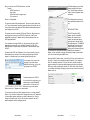
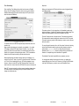
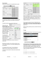
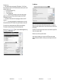
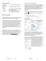
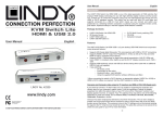
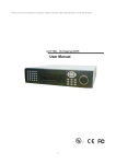
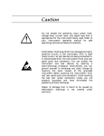
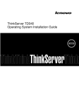
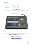
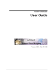
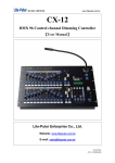
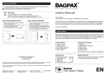
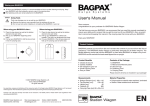
Contents:
UDP32S encoder
manual
Ø
Ø
Ø
Ø
Ø
Ø
Ø
Ø
Ø
Ø
Ø
Generates programmable UDP strings
32 inputs for 32 different strings
Quick & Easy Web-based configuration
DHCP, NTP, and HTTP
Two buffered RS232 outputs
Logs input triggers with timestamp
Strong extruded aluminum enclosure
Dual UDP destinations –
UDP strings can go to different ports
Flexible Time-based Event automation
One Year Limited Warranty
The UDP32S has 32 inputs – short an input to ground and the UDP32S generates
the corresponding (user-programmable) UDP string – the same string of characters
(full ascii support) is also sent out to both serial ports.
Configuration is super easy – the unit supports DHCP so you just plug it in and the
network configuration is automatic, or you can manually program the IP address
and other network particulars. The built-in webserver allows you to set up a text
string (up to 32 characters) for each of the 32 trigger inputs.
The UDP-32S has a built-in real-time clock, with configurable DST options and NTP
update capability. The clock is used for two major features: input logging, and timebased events.
The UDP32S has built-in 500+ event logging.
Three access levels grant full, limited, or read-only access to different users.
Coming soon – global delay setting – to fine-tune global UDP command delay to
match other higher latency data streams (video / audio for example).
Getting started
3
Finding your unit on the network
3
The web interface – setting unit IP address, UDP, serial, and logging
options
3-6
Setting the Real Time Clock
7
Setting up text strings
8
Using Automation
9-10
The logger
10-11
ADMIN functions
12
Specs and Warranty information
13
Appendix A – Alternate Network Setup / no DHCP
14
Appendix B – ASCII character table
15
Appendix C – Using your UDP32s in an XDS network
16
UDP32S User Manual
UDP32S Manual
Page |2
When you removed your UDP32S from the box, you found.
Contents:
UDP32S encoder unit
Power supply
D37male connector for trigger inputs
This user manual
The initial webpage you get to after
entering the password is shown
here. Note that there are five tabs
used for various configuration items
and actions.
Section 1: Getting Started:
The Configurations tab sets up the
basic operational parameters of the
unit.
The power connection is fairly straight-forward. There are two power jacks on the
unit. They are diode-steered, so power plugged into either jack will power the unit.
Using a second power supply (ideally fed from a different outlet/breaker) allows for
power redundancy into the unit.
The network connection is standard 10/100 base-T Ethernet. When powered up
and plugged into the network, your UDP32S will initially be in DHCP mode,
automatically acquiring an IP address and other network particulars from your
DHCP equipped network.
If your network doesn’t support DHCP, you will need to manually set up the IP
parameters by accessing the unit on its default IP address: 192.168.1.200.
Additional details on this procedure are in Appendix A, Alternate Network Setup /
no DHCP.
On networks with DHCP, the IP address of your unit can be found by using your
internet browser on a windows PC on the same physical and logical network
segment. In the address bar of your browser type udp32s and hit enter.
Your computer will try to resolve the
name and if your network allows
NetBIOS calls (most do), you’ll get the
login prompt for your UDP32S
NETWORK SETTINGS:
The DHCP-acquired, LAN IP
address, the units unique MAC
address (like a network serial
number), and the active http port
being used are in the upper right of
the configurations tab. The NetBIOS
Hostname can be changed, which
might be helpful if you have more
than one unit on the same LAN and
you want them to be accessible individually by NetBIOS name instead of IP
address, or if you want them to show up with meaningful usage or location data if
an IP scan is done showing the NetBIOS name.
Next is the Static IP address setting. Leave this 0.0.0.0 if you plan to keep the unit
on DHCP, or change it to your desired new static IP address. If you change the
Static IP to something other than 0.0.0.0 you’ll be able to manually change the
greyed-out settings for subnet mask, default gateway, and primary and secondary
DNS servers, if they are different for the static IP. DHCP will be turned off (when
you click Save at the bottom of the page) and you will need to browse to the new IP
address of the unit.
The default password is 12345678.
If you don’t get to the login screen, your
network may not work with NetBIOS
name resolution. In that case, an IP
scanner tool is your next best bet.
Please consult your IT department, or network admin.
The next step is to either record the IP address for future use, or assign a static IP
address. If you choose to assign a static IP address make sure your IT department
or network admin approves and gives you a valid IP address to use. Once you
change the IP address of the unit, your PC will need to be able to “see” the IP
address assigned to continue configuring the unit.
UDP32S Manual
Page |3
UDP32S Manual
Page |4
Behavior Settings:
Below the network settings are the behavior settings.
The configuration items control where UDP strings
are addressed to, the behavior of the serial ports,
and a few logging options.
The UDP destination IP addresses are set here.
You can have the device send your UDP strings
to more than one device (IP address) if desired.
Additionally, the IP port for each string is
separately settable on the Sequences tab.
The logfile primarily indicates what string was triggered/sent in the order they occur,
so the time/date stamp option is usually checked. If you are using multiple UDP32
units, adding the serial number to the log can be useful so it’s simple to distinguish
which unit the log is for. If you do not need to be reminded which encoder the log
event was generated by, leave this unchecked to conserve memory. The smaller
the footprint of the log file (fewer characters), the more log entries can be
maintained in it. Sequence number and sequence string are two labels that
indicate which string was triggered. The sequence number directly correlates to the
physical input- trigger pin on the d37 connector. The sequence string is the entire
text string sent out by the unit when triggered. The screenshot below shows the
logfile with all options turned on.
Key: Result, port, s/n,date, time, trigger #, sequence
Additional information on the
logger functions can be found
on Page 10.
The unit can “transmit UDP in the blind” if you uncheck the “Only transmit to established
connections” box.
Global Transmit Delay sets how many
milliseconds (10ms resolution – up to 2.55
seconds) the unit will pause before sending the UDP string. This feature is
sometimes used to match the audio propagation delay through an IP codec. This
setting does not affect serial output.
UDP Packets per trigger allows for sending the triggered string multiple times –
does not affect serial output.
Baud rate sets the speed of the serial ports. Rates of 300 baud to 57600 baud are
supported. The two serial ports are transmit-only, and are hard-coded for 8/N/1 (8
data bits, no parity bit, and one stop bit). Every string triggered/transmitted by the
UDP encoder is simultaneously transmitted on the serial ports. The two serial ports
transmit identical data at exactly the same time.
After any changes are made – you must click SAVE at the bottom of the page for
them to become active. Some settings (IP related) require rebooting the unit –
you’ll be prompted.
Global Input debounce refers to the time that must lapse between two triggers of
the same input before the second trigger will be considered valid. The initial trigger
is acted on immediately. If a second trigger occurs before the debounce period has
elapsed, the second trigger will be ignored. The default setting of 50 should
alleviate all “contact bounce” issues from old or “noisy” relay or switch contacts,
while allowing each trigger to be activated up to 10 times per second.
The next two settings determine what the serial ports transmit, in addition to all
strings that are triggered. “Display unit information on boot,” if checked, will send
include serial number version and IP address through the serial ports ONLY at
startup / reboot. “Display IP on change,” if checked, will transmit the unit’s IP
address through the serial ports any time it is changed through configuration
settings or DHCP.
The last four checkboxes determine how much data is included in the logfile.
UDP32S Manual
Page |5
UDP32S Manual
Page |6
Time / Date settings:
Sequences:
Click on the Date / Time Settings tab to set the time, time-zone, and Daylight
Savings Time (DST) settings of the built-in real-time clock, as well as enable or
disable automatic update of the minute and second by the NTP protocol (more
about this under the ADMIN tab)..
Setting up what gets sent via UDP (and serial) when an input is triggered is done
on the Sequences tab.
The header is optional – if text is entered here, it will immediately precede every
string that is triggered. If multiple UDP packets per trigger are enabled (page 5) the
header will also be repeated at the head of each instance of the string.
There are 32 sequence slots on the sequence tab. Each sequence (numbered 132) corresponds to the same input-trigger pin number on the unit’s D37 connector.
To program a sequence, just type in the characters you want to use, and click save
when you are done.
The real-time clock on the UDP32s keeps reasonably accurate time, within a few
seconds a day.
More accurate time-keeping may be required by your application – if so, enable
NTP update by setting the NTP update interval (in minutes). If you are using
primary NTP servers on the public internet, it is considered good form to set the
interval to 60 or greater to avoid overtaxing the resource. If NTP is unavailable or
disabled, the unit will keep time strictly by its internal real-time clock.
For non-printing ascii characters, click on the “Allow codes” check box for the string
and use the ascii decimal number for each non-printing character, enclosed in
pointy-brackets. Sequence01<13><10> is a string composed of the plain
alphanumeric text, Sequence01, followed by carriage return and line feed ascii
characters. A complete listing of ascii characters is in appendix B.
The destination IP port must be specified for every sequence you set up.
Manually setting the time and date can be done directly on the webpage, or by
using the “Sync with PC” button. Sync with PC will send the current PC time to the
unit. Click on “Save” immediately after sync. GMT offset is dependent on your
time-zone. Keep in mind that NTP uses GMT (Greenwich Mean Time) and will
reset the hour to an incorrect value if the GMT offset/ Time zone is not correctly set.
You can trigger the sending of a text string in three ways – by triggering the
corresponding input pin on the unit’s d37 connector, by clicking on the RUN button
to the right of the Sequence you want to send, or with Automation Events.
Since DST is not used universally, and the government sometimes changes when
DST starts and ends, the last settings allow you to enable or disable DST and
change when it starts and ends.
UDP32S Manual
Page |7
UDP32S Manual
Page |8
Events (Automation):
Automation events can trigger a string to be transmitted based on time and date.
You can create up to 10 automation events, Event status for defined events as well
as selection of which of the ten slots you want to modify is in the right half of the
window.
The left side of the window is where you create each automation event.
One-time events (as seen
above) are very simple – first
click on the first unused (greyedout) slot on the right side. Then,
on the left, specify the sequence
you want to trigger and the date
and time you want it to occur
(MM-DD-YY and HH:MM:SS in
24-hour format), then click
“Enable event,” and “Save.”
Sequence 1, starts September 1st, 2013, occurring every weekday at 1:58:50 AM
with no end date. Sequence 27 starting January 1st, 2014, occurring every hour of
every day at 58 minutes and 55 seconds past the hour, ending Jan 1st, 2015.
Sequence 31, active since June 20, 2013 occurring every day at exactly 12 noon,
expiring after 600 occurrences.
All three programmed automation events are green, indicating that they are not
expired or disabled. You can click on any slot on the right and the settings for that
slot (along with the status, next occurrence, and number of past occurrences) will
appear on the left.
Remember to enable any events that you want to occur and click “Save” when your
editing is done.
The Logger:
The onboard log is accessed by clicking on “view Onboard Log” button near the top
of the screen:
For recurring events, the
selections change depending on
the pattern and how often you
want an event to occur.
Recurring events can also be set
to stop occurring on a certain date, after a set number of occurrences, or to
continue “forever.”
Before defining a new automation event, be sure that you’ve clicked on an event
slot (on the right) that you want to use – the unit does not automatically advance to
the next inactive slot.
In the example above and right, sequence 1 will occur at the beginning of
September 2013 and will occur every weekday at 00:58:50 AM “forever.”
In the figure below, the status portion of the window shows three automation events
and their status.
A text file window will open up showing all log events up until the point you clicked
the View Onboard Log button. The log is arranged with newest data at the top and
oldest at the bottom chronologically. The onboard logger has enough memory for
about 500 verbose log messages. Reducing or increasing the amount of text in
each line of the log (optional settings on the Configurations tab) will correspondingly
change how many triggers can be stored in the log.
Sample log text.
GF,11000,000020,12-10-13,17:40:54.28,04,Sequence 04
GF,11000,000020,12-10-13,17:40:50.08,03,Sequence 03
GF,11000,000020,12-10-13,17:40:46.24,02,Sequence 02
GF,11000,000020,12-10-13,17:40:44.33,01,Sequence 01<13><10>
UDP32S Manual
Page |9
UDP32S Manual
P a g e | 10
Decoding the log:
GF = result codes for primary and secondary UDP destination. F=fail, G=Good
Since we didn’t set up the second UDP destination address, delivery to the second
destination failed to occur.
11000 = port set for the destination IP(s).
000020 = serial number of unit
12-10-13 = Date of logged trigger
15:40:54.28 = Time (down to the hundredth of a second) the sequence began
sending – this can be up to 2.55 seconds after the trigger occurred if Global
Transmit delay is set to 255.
04 = The sequence number (same as the input-trigger pin number on the D37
connector)
Sequence 04 = The text string programmed for the triggered sequence. Note that
the optional header text is NOT included in the log, just the sequence string itself.
The ADMIN tab:
The log text file can be downloaded from the UDP32s from the ADMIN tab.
The log can be cleared by clicking on the Clear Onboard Log button.
Here you can do more than the aforementioned log download. You can set up
different passwords for different levels of access: Admin (the default 12345678) can
do everything.
Right-click on the
up the Windows save-file dialog.
Controller can see all and trigger sequences from the web interface using the RUN
button on the sequences page.
button, then select Save Target As to bring
Reader can only view the log and tab contents.
Import or export of settings so you can clone one UDP32s to another, remote
restart, reloading factory defaults, and loading a new web image are all done from
this tab.
UDP32S Manual
P a g e | 11
UDP32S Manual
P a g e | 12
Specifications and Warranty
Power requirements
backup power
Network Interface
NTP
Environmental
Trigger inputs
APPENDIX A – Alternate Network Setup / no DHCP
9V to 15V AC or DC at 100mA max, supports
10/100 Base-T Ethernet, HTTP, UDP, DHCP,
32 to 110 degrees F < 90% (non-condensing) humidity
Not for use in wet locations.
D37F on unit. Male mating connector supplied.
Pins 1-32 are trigger inputs. 33-37 are ground.
If your network does not support DHCP, the UDP32S will need to be accessed on
its default IP address of 192.168.1.200. CHECK WITH YOUR IT STAFF BEFORE
PROCEEDING – THEY MAY PREFER TO HAVE YOU CONNECT TO THE
UDP32S WITH A CROSS_OVER CABLE FOR THIS PROCEDURE IF THE LIVE
NETWORK IN QUESTION USES THE SAME ADDRESS SPACE IN THESE
INSTRUCTIONS.
In Windows – access your Network and Sharing Center (right-click on your network
connections icon
if it is visible in the Task Bar, or find your network settings
under Control Panel).
Warranty and service information
Click on Local Area Connection Status
Warranty: Etherstuff products enjoy a 1 year limited warranty against manufacturing
defects. Damage caused by abuse will not be covered by this warranty.
Then click Properties.
Select Internet Protocol
Version 4 (TCP/IPv4) and
click Properties.
Disclaimer: The manufacturer reserves the right to make changes to this document
or the product it describes without notice. The manufacturer shall not be liable for
editorial or technical errors made herein. The manufacturer shall not be liable for
incidental or consequential damages resulting from the furnishing, performance, or
use of the product or this document. Manufacturer makes no warrantee of fitness
for any particular purpose. This product MAY NOT BE USED IN ANY
APPLICATION WHERE MALFUNCTION MIGHT POSE A RISK TO ANYONE OR
ANYTHING.
Service: Should your unit require service, contact our support specialists for
troubleshooting assistance and an RMA before sending the unit back to us. Include
your name, company name, contact information, unit serial number, and a brief
description of the problem and email to [email protected]. We try to
answer support and RMA requests within 8 business hours.
The next window that opens up will allow you to define the network address space
you want to communicate on. If your settings already have numeric values in them
and the “Use the following IP address” box is checked - Before malking any
changes write down all of the current settings.
Next set the IP address of your PC to 192.168.1.100
and the subnet mask to 255.255.255.0 and click OK.
You should now be able to browse to the UDP32s at
192.168.1.200 and configure its network settings for
your non-DHCP network. When you are done and
have saved the UDP32s configuration, change your
computer’s IP settings back to what they were
previously and click ok. When you close out of your
network settings you should be able to browse to the
UDP32s at the address you configured it for.
UDP32S Manual
P a g e | 13
UDP32S Manual
P a g e | 14
APPENDIX B – ASCII Character Table
APPENDIX C – Using your UDP32S in an XDS environment
Printable characters include the alphabet in lower and upper case, numbers 0-9,
and the following additional characters – ! @ # $ % ^ & * ( ) ` - _ = + { [ } ] | \ : ; ” ’ <
,>.?/
The UDP32S has been tested and verified by X-Digital Systems to properly
generate UDP or serial messages for cues and spot insertion triggers for
automation and regionalized events.
All printable characters can be entered into a string definition without using ASCII
codes, just use the character.
Relays
The non-printable (Control Code)
ASCII characters are entered using
their decimal code number, inside
pointy brackets <xx>. The Allow
Codes checkbox must be checked
for the UDP encoder to recognize
the bracketed numbers as ASCII
codes and send them accordingly.
A UDP32S string defined as below:
RELAY07<10><13>
(as long as Allow Codes checkbox
is checked) will produce a string
with the characters RELAY07
followed by the ASCII codes for
line feed and carriage return,
respectively.
To initiate a relay closures on an XDS Receiver, the entry on the Sequence line
(see page 7) will need to be configured exactly the same (i.e. case sensitivity and
use of spaces) as listed on the Relay Code on the Program Definition page of the
XDS NMS. Additionally, the entry will need to be preceded with a C: A properly
configured relay message will look like:
C:CueCode
The port value (next to the sequence string) is determined by your XDS
administrator. Please consult them for the proper value to enter in this field.
Spot Insertion Triggers
Spot Insertion Triggers functionally work the same as relays; however, there are
additional variables that must be included. A spot insertion trigger begins with a 1:
and utilizes the following format:
1:PgmCode:CueCode:ISCICode:Flag
The Program Code is listed on the Program Definition page of the XDS NMS. It is
case sensitive and can only contain 5 characters or less.
Cue Code is the ad specific message entered on the Insertion Instruction for a spot
insertion.
ISCI Code can be used for tracking purposes, although it is not necessary. It is
acceptable to simply input 0 (zero) for this field.
There are three choices for the Flag entry. F is the most common.
‘F’ when the cue identifies the first spot in a break set.
‘L’ when the cue identifies the last spot in a break set.
‘M’ when the cue identifies a mix between inserted and national spots.
For more information regarding the context of your UPD or serial messages, please
consult your XDS administrator.
UDP32S Manual
P a g e | 15
UDP32S Manual
P a g e | 16