1
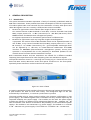
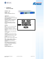
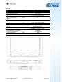
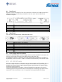
ES10 – La
ES10 – Xla
SSO 689A
Optical Transmitter 1550 nm
Operating Manual
Safety instructions
Attention:
Please read the instructions completely and
carefully
before putting into operation!
All operation steps should be carried out in the
prescribed sequence!
Improper putting into operation can cause serious
danger for persons or damage the devices.
INVISIBLE LASER RADIATION
DO NOT STARE INTO BEAM OR
VIEW DIRECTLY WITH OPTICAL
INSTRUMENTS
CLASS 3A LASER PRODUCT
MAXIMUM OUTPUT POWER:
50mW
WAVELENGTH: 1550nm
IEC 825-1; 1993
Funea Broadband Services bv
version: 11-02
product information
page 2 of 31
Warranty
All products manufactured by BKtel communications GmbH are guaranteed to be free from
defect in material and workmanship for a period of one (1) year from the date of shipment.
During the warranty period, BKtel communications GmbH will repair, or replace at its option , any
product or parts thereof of BKtel communications GmbH which have been sold by BKtel
communications GmbH or authorised representatives to the Buyer, where such products or parts
thereof, upon inspection by BKtel communications GmbH and in the sole opinion of BKtel
communications GmbH are determined to be defective in workmanship or material. BKtel
communications GmbH reserves the right to issue a credit note for any defective product or parts
thereof, as determined by BKtel communications GmbH, as an alternative to the repair or
replacement of such defective product or parts thereof. This warranty shall extend to all products
and parts thereof which have been proved defective through normal use, but this warranty shall
not cover any products or parts thereof that have been subjected to conditions exceeding the
applicable specifications or ratings for such products or parts thereof, or such products or parts
thereof which have been disassembled, modified or otherwise abused.
Buyers must notify BKtel communications GmbH in writing of any warranty claim not later than
30 days after the expiration of the warranty period. Any claims under this warranty must be made
by the Buyer, and no claim will be accepted from any third party. All claims for shortage of
products ordered, or for incorrect charges, must be presented to BKtel communications GmbH
within 10 days after shipment of products by BKtel communications GmbH.
Limitation
The remedies provided for above are the Buyer’s sole and exclusive remedies. BKtel
communications GmbH shall not be liable to a Buyer, or any other third parties, for installation
and removal costs, or for any other special, consequential or indirect damage, including without
limitation the loss of production or profit, arising from any cause whatever, even if BKtel
communications GmbH has been advised to the possibility of such damage or damages, or even if
such damage or damages is alleged to arise from negligent acts, omissions, or conduct of BKtel
communications GmbH or its employees. The liability of BKtel communications GmbH is expressly
limited to the replacement or correction of defective products or parts thereof, or to the issuance
of a credit note for the purchase price of such products or parts thereof. This warranty is in lieu of
all other warranties expressed or implied including, without limitation, any implied warranties or
merchantability or fitness for a particular purpose.
Repair Procedures
Defective products or parts thereof shall be returned to BKtel communications GmbH,
transportation pre-paid, at the address shown below, using the original packing carton or one
that will provide equal protection. All products or parts thereof which have been returned to
BKtel communications GmbH, but which are found to meet all previously applicable specifications
for such products or parts thereof, shall be subject to an examination charge of not less than $
250.00 U.S.. All products or parts thereof which are returned to BKtel communications GmbH, and
which are not accompanied by an itemised statement of defects shall be returned to the Buyer at
the Buyers expense, and no such evaluation of such product or part shall be carried out.
BKtel communications GmbH shall only accept returns for which an approved Return Material
Authorisation (RMA) has been issued.
Repairs are warranted for the remainder of the original warranty or 90 days, whichever is greater.
Claims for Shipping Damage
When the product is received by the Buyer, it should be immediately inspected for damage to the
product or shortages on the packing list. If the product is damaged, a claim should be filed with the
carrier. A quotation for estimated costs of repair can be obtained from BKtel communications GmbH.
Negotiation and settlement with the carrier must be accomplished by the Buyer.
BKtel communications GmbH, Benzstrasse 4, 41836 Hueckelhoven Baal, Germany
Phone: +49 (2433) 9122 0
Funea Broadband Services bv
version: 11-02
Fax:
+49 (2433) 9122 99
product information
Email:
[email protected]
page 3 of 31
TABLE OF CONTENTS
1
DOCUMENT STATUS
2
PARTS LIST
3
GENERAL DESCRIPTION
5
6
7
3.1
3.2
Introduction
Principle of Operation
7
8
4
TECHNICAL SPECIFICATIONS
11
4.1
4.2
4.2.1
4.2.2
4.2.3
4.2.4
4.3
4.4
4.5
4.5.1
4.5.2
4.5.3
4.6
Displays and Alarms
EMS / Service Interfaces
NMS server interface: Ethernet 10/100Mbps (ES10-XLa only)
Local Setup interface: RS232 (ES10-XLa only)
BK device bus interface: RS485 (ES10-XLa only)
BK device bus interface: RS485 (ES10-L only)
Front Panel
Rear Panel
Power supply and fan modules
100 – 240 VAC module
48 VDC module
24 VDC module
Labelling
15
15
15
15
15
16
17
17
17
17
18
19
19
5
OPERATING THE ES10
20
5.1
5.2
5.2.1
5.2.2
5.2.3
5.3
5.4
5.5
5.6
5.7
Power-Up Sequence
Applying an appropriate RF input signal
Mode: AGC-on, CW unmodulated carriers (factory setting)
Mode: AGC-on, modulated carriers (user adjustable)
Mode: AGC-off, (user adjustable)
ITU frequency adjustments in DWDM applications (ES10-XLa only)
Optical power on /off
SBS suppression setting (ES10-XLa only)
LED Display
Push button / LCD interface
20
20
20
23
23
23
24
24
24
25
6
7
MAINTENANCE
TROUBLESHOOTING
27
28
Funea Broadband Services bv
version: 11-02
product information
page 4 of 31
1
DOCUMENT STATUS
Document
Operating Manual ES10-La / XLa
Revision
00
01
02
03
04
Date
23.05.02
18.07.02
23.08.02
27.08.02
27.09.02
Responsible
Seidenberg
Seidenberg
Hensel
Seidenberg
Seidenberg
Remarks
Document created
84 channel PAL-D specs
Operation
Operation Instructions
05
04.10.02
Seidenberg
EMI specifications included
Funea Broadband Services bv
version: 11-02
Introduction of ES10 – La and
-70, -85 and –100 versions
product information
page 5 of 31
2
PARTS LIST
This Document contains the description for the following units
transmitter unit
power supply +
fan module
optical interface
modular external modulated 1550 nm optical transmitter basic unit
power supply + fan module 100 VAC ... 240 VAC
power supply + fan module 36 VDC ... 60 VDC
power supply + fan module 24 VDC
SC-APC optical connector, 8° angle (default)
SC-APC optical connector, 9° angle (option)
FC/APC optical connector, JDS-standard (default)
FC/APC optical connector, NTT-standard (option)
E2000 - 0.1 dB optical connector
HRL-10 optical connector
The ES10 is as an OEM product available with a customised front panel print.
Funea Broadband Services bv
version: 11-02
product information
page 6 of 31
3
3.1
GENERAL DESCRIPTION
Introduction
The optical transmitter BK-ES10 represents a family of externally modulated 1550 nm
DFB laser transmitters. These products have been developed to fulfil the requirements
of modern Hybrid Fiber Coax networks for the transmission of CATV, cable phone and
cable data signals. There are currently 2 different base versions available:
•
ES10-La for applications with moderate fiber length of about < 50 km
This version features a SBS threshold of 16.5 dBm, a narrow linewidth laser (0.65
MHz), output powers of 2 * 7 dBm (-70 version) or 2 * 8.5 dBm (-85 version) and a
RS485 interface for EMS (element management systems).
For highest requirements on transmission performance and features the
•
ES10-XLa for applications with very long fiber lengths exceeding 50 km
is proposed. This version offers a SBS threshold which can be adjusted between 13
and 19 dBm, a very narrow linewidth laser (0.3 MHz), output powers of > 2 * 8.5 (85 version) or > 2*10 dBm (-100 version), ITU – grid compatible wavelength which
can be adjusted by +/- 100 GHz, an 10/100 Ethernet webbrowser and SNMP
interface for EMS/NMS (element/network management systems). Future proof
operation is accomplished due to the possibility to download updates for the
network server firmware and the transmitter firmware.
Both transmitters ES10-La and XLa transmitter are offered for 5 different standard
frequency plans. Specifications for other frequency plans are available on request.
The optical transmitter comes in a 1 unit high 19“ housing. Fig. 2.1 shows the view of an
ES10 with RFin socket, RFmonitor socket and optical connectors on the front panel.
Optionally these connectors can be located on the rear panel.
Figure 2.1: View of ES10
A Liquid Crystal Display (LCD) provides information about actual settings and properties.
6 push buttons are used to enter data locally. The background light of the LCD
automatically is switched on, in case that a push button is pressed.
The ES10 provides plug in power supply modules. The minimum configuration is one
power supply + fan module together with a redundant fan-only module. Optionally for
improved reliability two power supply + fan modules can be used. The power supply
modules are offered in 3 different input voltage specifications: 100 ... 240 VAC, 36 ... 60
VDC and 24 VDC. One feature of the ES10 is the possibility to use two different power
supply + fan modules in one transmitter: e.g. power supply + fan module no. 1 could be
a 100 ... 240 VAC unit, power supply + fan module no. 2 could be a 36 ... 60 VDC unit.
Funea Broadband Services bv
version: 11-02
product information
page 7 of 31
The optical interface can be ordered with different optical connectors as specified in the
parts list (pls. ref. to 2). It is also possible without the need of using special tools to
change the optical interface by replacing the optical connector interface plate by
another one as specified in the parts list.
For an EMS (element management system) or a NMS (network management system) an
Ethernet 10/100 MBps interface is available at the rear side of the ES10-XLa. This
Ethernet interface supports SNMP and Webbrowser protocols. The IP address for the
Webbrowser interface can be set using the push buttons at the front panel or the RS232
local set-up port at the rear side.
An additional RS485 (master) interface has been implemented at the ES10-XLa to poll
other equipment like EDFAs or optical switches which are connected to the local RS485
management bus.
The ES10-La offers a RS485 for EMS or NMS. An external level converter from RS485 to
RS232 can be offered on request to connect the ES10-La to standard PC-COM1 or -COM2
interfaces.
3.2
Principle of Operation
The transmitter is based on 5 functional blocks: RF-path, CW-DFB-Laserdiode, integrated
optical modulator, control electronics and power supply. The functional diagram is
given in fig. 2.2.
The RF input signal is fed into a preamplifier comprising an automatic gain control
circuitry. The AGC stabilises the output signal of the preamplifier to maintain a stable
RMS- (root-mean-square) optical modulation index (OMI) of the optical modulator.
Input level variations are compensated as long as the AGC circuit is working in its
nominal gain range (ref. to chapter 3).
The AGC can be adjusted turned off for a constant gain operation via the push buttons,
or the Ethernet interface in order to tailor the CNR/CSO/CTB performance to the used
frequency plan and the requirements of the customer by using a different input level.
The electrical RF-signal is fed via a highpass circuit to the input of a predistortion circuit
which is foreseen to linearize the squared sine wave transmission function of the
electrooptical modulator. The predistortion circuit is requested to minimise 3rd order
intermodulations (CTB = composite triple beat). The output signal of the predistortion
circuit is amplified to proper input level for the electrooptical modulator, to establish a
sufficient modulation depth of the optical output signal.
The central core of the transmitter is the electrooptical modulator working as a MachZehnder-interferometer. The light from the laserdiode is coupled to an optical strip
waveguide. An integrated optical splitter divides the light into two identical portions
which are phase modulated by an RF signal applied to the electrodes of the modulator.
The concept of the electrodes results in an push pull phase modulation of both
branches. Following the modulating section the signals of both arms are combined and
interfere. The interference of the phase modulated signals results in an amplitude
modulation of the output light signal which is available on both outputs of the
combiner.
The necessary CW input light for the modulator is produced by a DFB laserdiode
working with a wavelength between 1550 and 1560 nm. There are two control loops
for operating the laserdiode at constant optical output power as well as at constant
temperature by means of a thermoelectric cooler. The ES10-XLa has been designed for
DWDM applications and allows to change the operation frequency (wavelength) by +/100 GHz in steps of 50 GHz. The laserdiode drive current is measured to detect an
increase to 130% of the initial value which could be caused e.g. due to ageing of the
laserdiode. The temperature of the laserdiode is supervised by measuring the required
drive current for the thermoelectric cooler. At 90% of the available cooler drive current
Funea Broadband Services bv
version: 11-02
product information
page 8 of 31
and/or >130% of the initial laserdiode drive current a B-grade alarm which indicates a
warning is generated. At 100% cooler drive current the laserdiode drive current is
switched off to protect the laserdiode against irregular temperature conditions and an
A-grade alarm indicating a severe malfunction is generated. Both types of alarms are
causing the corresponding LED on the front plate of the optical transmitter to emit. In
case of a B-grade alarm the yellow LED is lighting since the unit is still working properly,
however close to its limits. In case of an A-grade alarm the red LED is emitting. The
messages to the network management system are of course more detailed. They include
the actual values of the currents and temperature as well as alarm flags.
To suppress the Stimulated Brillouin Scattering (SBS) the optical signal is broadened.
Two technologies are used:
•
Broadening the optical spectrum by modulating the laserdiode with a microwave
signal
•
Broadening the optical spectrum by driving a optical phase modulator with a
microwave signal
These circuits are mandatory to avoid stimulated brillouin scattering (SBS) in optical
fibers and allow to operate with optical amplifiers feeding at least +13 dBm of optical
power into standard single mode fibers (ref. to chapter 3.1). All microwave signals can
be adjusted in amplitude via the push-buttons on the front panel to optimise the SBS
and SPM (self phase modulation) performance for the XL-version of the transmitter
(ICS1 or higher).
The coupling of light from the laserdiode to the modulator is performed using a
polarisation maintaining optical fiber. The optical modulator provides two optical
outputs. The signal of one of these outputs is tapped and led to an InGaAs photodiode.
The electrical signal of this photodiode is evaluated for two reasons:
1) To supervise a proper working of the CW laserdiode. In case of optical output power
drop of 2 dB of nominal power an B-grade alarm (=warning alarm) is generated, in case
of optical output power 0 dBm an A-grade alarm (=urgent alarm) is generated.
2) A detector circuit measures CSO and CTB distortions to optimise the bias point of the
electrooptical modulator. For a proper operation of the detection circuit at least two TV
carriers with a frequency spacing of 24 MHz have to be present. Using this standard
software setting of the detection scheme all known European and Chinese frequency
plans are supported: CENELEC frequency plan, all regular 8 MHz spacing frequency
plans as well as the German 7/8 MHz frequency plan. Additionally it is possible to
change the standard software setting to work with regular 6 MHz frequency plans
(NTSC) or pure 7 MHz frequency plans via push-buttons on the front panel or via the
NMS interface.
The ES10XLa is equipped with 3 data interfaces at the rear side:
•
RS232 for a local set-up of the NMS Interface,
•
RS485 for polling other BKtel equipment like EDFAs or optical switches and
translating this information to the Ethernet interface,
•
Ethernet 10/100 MBps supporting SNMP and Webbrowser protocols for
interfacing to a EMS or NMS
The ES10XL is equipped with a RS485 interface for interfacing to a EMS or NMS.
Plug in power supply/fan modules for different input voltages are available for 100 ...
240 VAC, 36 ... 60 VDC and 24 VDC. Each module can be simply removed during
operation without disturbing the operation of the transmitter by removing 2 screws.
Funea Broadband Services bv
version: 11-02
product information
page 9 of 31
RS 232Interface
Ethernet Interface
Liquid crystal
display +
push buttons
RS485 Interface
Input
Monitor
RF - Input
RF - Monitor
Figure 2.2: Main functions of ES10-Xla
Funea Broadband Services bv
version: 11-02
product information
page 10 of 31
4
TECHNICAL
SPECIFICATIONS
ES10XLa – xxx
ES10La - xxx
Optical Transmitter 1550 nm
Application
Electrical to optical conversion of
multichannel CATV signals like AM-VSB,
FM and QAM signals
Enables the usage of optical amplifiers
(EDFAs) as boosters or repeaters in
order to realize large scale HFC
networks
Excellent performance in order to
realize links exceeding 100 km (XLVersion)
E th e rn e t
or
R S 485
LC D
u P
o p t. o u tp u t # 1
o p t. o u tp u t # 2
Features
Low noise, narrow linewidth CW-DFB
laser
ITU-Grid wavelength (XL-Version)
Wavelength adjustable +/- 100 GHz (XLVersion)
Electrooptical modulator with 2 optical
outputs
Automatic RF gain control: CW, video,
manual mode
> 2 * 10 dBm output power (XLa-100Version)
Adjustable SBS threshold up to 19 dBm
to increase transmission distance (XLVersion)
Frontpanel RF test point –20 dB
Dual, hot-plug-in power supply modules
for
100 .. 240 VAC, -48 VDC, +24 VDC
Web and SNMP Interface (XL-Version)
RS232/RS485 control interface (LVersion)
Built-inNetwork Element Controller to
poll slave devices like Bktel Optical
Switches and Bktel Optical Amplifiers
(XL-Version) via RS485
LC display
LED status indication
Very thin design, only 1 HU
Funea Broadband Services bv
version: 11-02
product information
R F in
R F m on.
page 11 of 31
ES10-XLa
Optical Properties
Wavelength
ITU-grid (CH23… CH33)
Wavelength adjustment range
[GHz]
+/- 100 in steps of 50
Optical power, ES10-XLa-85
[dBm]
2 x 8.5 min.
Optical power, ES10-XLa-100
[dBm]
2 x 10.0 min.
SBS-Suppression
[dBm]
Threshold adjustable between +13 and 16.5
(optional 19) dBm
Laser linewidth (typ.)
[MHz]
0.3
[MHz]
47 –1000
Electrical Properties
RF-Frequency Range
Flatness
[dB]
<±0.75 (47...860 MHz)
Version xxx
<±1.5 (860 MHz...1 GHz)
C42
B52
D59
D84
N77
Channel plan
CENELEC
42
PAL-B/G
PAL-D 59
PAL-D
84
NTSC 77
number of channels
TV / FM (-4dB) / QAM64 (-10dB)
42 / 0 / 0
52 / 36 /
46
59 / 0 / 0
[MHz]
5
5
5
5
4
CNR Tx/Rx
[dB]
55.5
53.5
54.0
52.5
53.5
CNR Link 1
[dB]
55.0
53.0
53.5
52.0
53.0
CNR Link 2
[dB]
53.0
51.0
52.5
50.5
52.0
CNR Link 3
[dB]
50.5
49.5
50.5
49.0
50.0
CSO Tx/Rx and Link 1
[dBc]
64
70
65
65
65
CSO Link 2
[dBc]
63
70
65
65
65
CSO Link 3 at output #1
[dB]
62
65
65
63
65
CTB
[dBc]
65
71
65
65
65
Noise bandwidth
Control interface
84 / 0 / 0 77 / 0 / 0
Ethernet 10/100 interface, Webbrowser and SNMP
Test Configurations
Booster
EDFA
1 Fiber
Length
In-Line
EDFA
2 Fiber
Length
RX
Tx/Rx
no
no
No
no
0 dBm
Link 1
no
35 km
No
no
0 dBm
Link 2
16 dBm
65 km
No
no
0 dBm
Link 3
13 dBm
52 km
13 dBm
52 km
0 dBm
st
nd
RX with 7 pA/√Hz input noise current density
EDFAs with 5dB noise figure
RF input level at 80 dBuV / TV channel
Funea Broadband Services bv
version: 11-02
product information
page 12 of 31
ES10-La
Optical Properties
Wavelength
1550.....1560
Optical power, ES10-La-70
[dBm]
2 x 7.0 min.
Optical power, ES10-La-85
[dBm]
2 x 8.5 min.
SBS-Suppression
[dBm]
Fixed threshold +16.5 dBm
Laser linewidth (typ.)
[MHz]
0.65
Electrical Properties
RF-Frequency Range
Flatness
[MHz]
47 –862
[dB]
<±0.75
Version xxx
C42
B52
D59
D84
N77
Channel plan
CENELEC
42
PAL-B/G
PAL-D 59
PAL-D 84
NTSC 77
number of channels
TV / FM (-4dB) / QAM64 (-10dB)
42 / 0 / 0
52 / 36 /
46
59 / 0 / 0
84 / 0 / 0
77 / 0 / 0
[MHz]
5
5
5
5
4
[dB]
55.5
53.5
54.0
52.5
53.5
54.0
52.5
53.0
51.5
52.5
Noise bandwidth
CNR Tx/Rx
CNR Link 1
CNR Link 2
[dB]
51.0
50.5
51.5
49.0
51.0
CNR Link 3
[dB]
48.5
48.0
49.0
46.5
48.5
CSO Tx/Rx and Link 1
[dBc]
64
70
65
65
65
CSO Link 2
[dBc]
63
70
65
65
65
CSO Link 3 at output #1
[dB]
62
65
65
63
65
CTB
[dBc]
65
71
65
65
65
Control interface
RS485 or RS232 via external level converter
Test Configurations
Booster
EDFA
1 Fiber
Length
In-Line
EDFA
2 Fiber
Length
RX
Tx/Rx
no
no
no
no
0 dBm
Link 1
no
35 km
no
no
0 dBm
Link 2
16 dBm
65 km
no
no
0 dBm
Link 3
13 dBm
52 km
13 dBm
52 km
0 dBm
st
nd
RX with 7 pA/√Hz input noise current density
EDFAs with 5 dB noise figure
RF input level at 80 dBuV / TV channel
Funea Broadband Services bv
version: 11-02
product information
page 13 of 31
General
Wavelength
Side mode suppression
Relative intensity noise
(opt. return loss < -40 dB)
Opt. Connector
Optical fiber
Nom. Input level per TV
channel
dynamic range of AGC
RF-connector/ impedance
return loss
Climatic Specification
Operation
Storage
EMI
Power Supply
Dual redundant, hot pluggable
(3 Versions are available)
Power Consumption
Enclosure
Weight
Funea Broadband Services bv
version: 11-02
[nm]
[dB]
[dBc/Hz]
[dBµV]
[dB]
[dB]
[W]
[kg]
1550 … 1560
>30
<-158
typ. <–160
any type of high return loss connectors
front or rear side mounted
standard singlemode 9/125 µm
80
+2 ... –4
IEC 169-2, 75 or F-female, 75
front or rear side mounted
> 20 (47 MHz) – 1,5 dB/oct., min. > 15
ETS 300 019, class 3.1
ETS 300 019, class 1.2
EN50083-2 (April 1996)
EN50083-2 /A1 (February 1998)
100...240 VAC
36...60 VDC
or 23.5...24.5 VDC
<=60
19” / 1 RU
9.7
product information
page 14 of 31
4.1
Displays and Alarms
Modul LED
Standard Operation
LED green
non urgent alarm (warning)
LED yellow
LED red
urgent alarm
OUT LED
4.2.1
loss of output power
LED green0
LED yellow
LED red
standby – operation
LED dark
nominal input power
input power out of nominal operation
loss of input power
IN LED
4.2
nominal output power
lack of output power
LED green
LED yellow
LED red
EMS / Service Interfaces
NMS server interface: Ethernet 10/100Mbps (ES10-XLa only)
The NMS server interface is the main NMS interface of the optical transmitter.
It supports HTTP and SNMP protocols.
See the document Bktel Device Management engl.pdf for more information about the
NMS server.
The NMS server firmware can be downloaded for future software upgrades via the
RS232 interface.
4.2.2
Local Setup interface: RS232 (ES10-XLa only)
Connector
Sub-D9 male
Configurations
115200 baud, 8 data, 1 stop, no parity
Interface
RS232
Pinning
Pin 1, 4, 6, 9: n.c.
Pin 2: RxD
Pin 3: TxD
Pin 7: RTS
Pin 8: CTS
Pin 5: Gnd
The local setup interface can be used to locally setup the NMS server's parameter, like IP
parameters and passwords by using the tool "NmsSetup.exe".
Additionally it must be used to software download the NMS server firmware in the case
that the NMS server crashes during software update when reprogramming application
flash software over Ethernet.
Note: The local setup process can only be executed when the device starts up. After
startup this interface has no meaning yet, but will be used for modem connections in
the future.
4.2.3
BK device bus interface: RS485 (ES10-XLa only)
The RS485 interface can be used to connect more devices to be managed by the
Ethernet NMS server interface together with the optical transmitter. The ES10XLa in
this case works as a network element controller, which polls all equipment that is
Funea Broadband Services bv
version: 11-02
product information
page 15 of 31
connected to the RS485 port. Information about the protocol can be obtain from the
document RS485 specifications.pdf.
4.2.4
BK device bus interface: RS485 (ES10-L only)
The RS485 interface can be used to manage the ES10L, that means to read data and to
change some settings. BKtel offers a WINDOWS based software tool to communicate
with the transmitter. Additionally, a RS485 to RS232 level converter can be offered. This
allows to run the software on any WINDOWS based PC and use the COM1 or COM2
ports to communicate with the ES10L via the RS485 interface.
Funea Broadband Services bv
version: 11-02
product information
page 16 of 31
4.3
Front Panel
Figure 4.1 shows an example of the front panel view of the ES10. The RF-input and the
optical connectors are optionally available on the rear panel. The handles can be
omitted on request.
Item #
1
2
3
4
5
6, 7
4.4
Function
RF-input (optionally available on rear side)
RF-monitor output
Status LED’s
Liquid Crystal Display
Push button field for local set-up of transmitter
Optical connectors (optionally available on rear side)
Rear Panel
The rear panel provides several field replaceable units:
4
Item #
4
1,2
4.5
4
Function
power supply + fan modules
RF-input (optional on front panel)
optical fiber outputs (optional on front panel)
RS485 interface (RJ-45 female)
RS232 interface (SUB-D9 male)
Ethernet interface (RJ-45 female)
2 green LED’s (Ethernet link & data)
Power supply and fan modules
There are 3 different types of power supply and fan modules available for the ES10. All
of them can be either mounted on the left hand or right hand side,
It is possible to replace or exchange all of the modules during operation. This offers a
big flexibility to the end user in order to customise the ES10 exactly to the actual needs.
4.5.1
100 – 240 VAC module
Figure 5.3.1 gives the view on the 100 – 240 VAC power supply and fan module. There is
a AC mains input. There is one LED informing about the status of the power supply
module. The power unit O.K. LED is lightening green provided that the power supply
module is working properly.
The power supply and fan modules my be exchanged during operation (hot plug-in
technology) with having neither harm to the equipment nor having any impact on the
operation of the transmitter in case of a properly working backup power supply.
Funea Broadband Services bv
version: 11-02
product information
page 17 of 31
Figure 5.3.1: 100 ... 240 VAC power supply and fan modules
4.5.2
48 VDC module
C€
+ -
DC-Line Input
36-78V DC
75W max, Fuse T2.0A
SV19" 1HE-48V
1910-0101 Ä01
007314
Figure 5.3.2 gives the view on the 48 VDC power supply and fan module. There is a 48
VDC cable terminal in order to connect the supply voltage. It is important to take care
of the right polarity of the DC supply voltage.
A fuse and a spare fuse are implemented inside the power supply and fan module and
maybe replaced if required. There is one LED informing about the status of the power
supply module. The power unit O.K. LED is lightening green provided that the power
supply module is working properly.
The power supply and fan modules my be exchanged during operation (hot plug-in
technology) with having neither harm to the equipment nor having any impact on the
operation of the transmitter in case of a properly working backup power supply.
Figure 5.3.2: 48 VDC power supply and fan modules
Funea Broadband Services bv
version: 11-02
product information
page 18 of 31
4.5.3
24 VDC module
Figure 5.3.3 gives the view on the 24 VDC power supply and fan module. There is a 24
VDC cable terminal in order to connect the supply voltage. It is important to take care
of the right polarity of the DC supply voltage.
A fuse and a spare fuse are implemented inside the power supply and fan module and
maybe replaced if required. There is one LED informing about the status of the power
supply module. The power unit O.K. LED is lightening green provided that the power
supply module is working properly.
The power supply and fan modules my be exchanged during operation (hot plug-in
technology) with having neither harm to the equipment nor having any impact on the
operation of the transmitter in case of a properly working backup power supply.
TBD, available in October 2002
Figure 5.3.3: 24 VDC power supply and fan modules
4.6
Labelling
The optical transmitter carries a label on the rear side of the top cover specifying the
transmitter type (-La, -XLa) the ordering number (e.g. 009618) the hardware and
software version (e.g.: ICS2) and the manufacturing code (e.g. 1812-0114). In case of
questions please specify all these information when communicating with BKtel or sales
representatives.
ES10XLa-19“
009618
ICS1
1812- 0114
Funea Broadband Services bv
version: 11-02
product information
page 19 of 31
5
OPERATING THE ES10
5.1
•
•
•
•
•
Power-Up Sequence
Be sure that the BK-ES10 is going to be put into operation under the specified
environmental conditions. Avoid temperature shocks after transportation of the BKES10 and allow sufficient time to accommodate with the environmental conditions
at the operating site.
If not already realised install the appropriate power supply + fan modules,
respectively fan-only modules.
Connect the BK-ES10 to one or two (in case of redundant power supplies)
appropriate power supply lines. If only one power supply line is connected to an
ES10 equipped with redundant power supplies, an alarm will be generated and
shown with a yellow brightening MODUL LED.
After start (with appropriate power line connections), the MODUL LED is lightening
green and the LCD illumination is on. Then the LCD illumination is switched off and
all front side LED’s are lightening yellow for a short time in order to enable a LED
test. Afterwards all LEDs should be lightening green and the microcontroller starts
to test the laser and optical modulator. During this test, which takes about 70
seconds, the optical output power on both outputs varies between zero power and
about twice the nominal power (Poutnom + 3 dB). Afterwards with no RF-input
signal applied, the output power may vary by about +/- 1 dB on both
outputs, since the CSO control loop, which fixes the bias point of the
modulator and consequently the output power, only works precisely with a
RF input signal applied.
After this procedure the LEDs should monitor the status of the transmitter.
5.2
Applying an appropriate RF input signal
With an appropriate input signal the transmitter starts to search for the optimum bias
point of the LiNbO3 modulator. After about 30 seconds, the optical output levels of
both outputs start to become stable.
A fiber optic cable with an appropriate, cleaned connector might be connected to one
of the optical outputs in order to feed a HFC network. Keep in mind that the BK-ES10 is
according to IEC 825 a laser class 1 product which requires adequate safety precautions
to avoid hazard to people working with the BK-ES10.
There are 3 AGC on/off RF modes which can be selected in order to operate the ES10.
5.2.1
Mode: AGC-on, CW unmodulated carriers (factory setting)
Most tests (CNR / CSO / CTB) are performed with unmodulated carriers using e.g. a
Matrix gebnerator or a CATV headend, where the modulation is switched off. These
tests should be performed with the “AGC-on, CW unmodulated carrier” mode. The
OMItotrms should be set to the factory setting (0 dBr).
This mode is also the recommended mode for standard operation with real picture
modulation. It should be understood, that for AM-VSB TV channels the carrier levels
with modulation decreases by about 4 dB, however, depending on the picture content.
This decrease in input level has to be compensated by the AGC for optimum signal
transmission.
For a proper operation an appropriate input signal has to be connected to the ES10. At
least 2 RF channels with a channel spacing of 24 MHz (software adjustable) are required
to obtain a stable performance of the BK-ES10.
The nominal channel load (factory settings) for the ES10xxx-yy family however is given
in the table below:
Funea Broadband Services bv
version: 11-02
product information
page 20 of 31
Model
yy
C42
B52
D59
D84
N77
# AM TV
channels
(0 dBr)
42
52
59
84
77
# FM
channels
(at –4 dBr)
0
36
0
0
0
# QAM64
channels
(-10 dBr)
0
46
0
0
0
TV channel
level
[dBµV]
80
80
80
80
80
Total rms
OMI
[%]
19.2
18.4
19.4
19.4
19.2
total level
[dBm]
-12.5
-10.8
-11.0
-9.5
-9.9
The ES10 has a built in RF power meter function, which monitors the total level at the
input of the transmitter as given in the right most column of the table beyond. This
level depends on the number of unmodulated and modulated AM-TV, FM-radio and
QAM channels.
The input monitor controls the INPUT LED. As long as the input level is within the AGC
range of the transmitter to obtain the specified total rms modulation index, the input
LED is lightening in green colour.
If the number of channels to be transmitted is differing from the specified number of
channels the total input power level can be calculated using the following expression:
Pintot/dBm = 10 log (n) + Uin/dBµV –108.7
where
•
•
•
Pintot is the total rms input power level
n is the number of channels
Uin is the input voltage per channel (nominal 80 dBµV) for unmodulated carriers.
If the input level voltage of all channels is 80 dBµV the diagram below can be used to
determine the total input power level.
Funea Broadband Services bv
version: 11-02
product information
page 21 of 31
Total rms input power for n unmodulated channels with 80 dBµV
total rms power in dBm
-10,00
-15,00
-20,00
-25,00
Example
1: The ES10Xla-PD84 is specified for 84 TV channels. The nominal input level
voltage per carrier is 80 dBµV which corresponds to an input level power of -28.7 dBm
for one unmodulated channel only. For 84 unmodulated channels the total input level
will be –9.5 dBm.
-30,00
The specified,
guaranteed AGC range of the ES10 is +3 / -6 dB. The recommended
0
30 77 ... 40
60
70
80 dBm90
standard input
level10range is20therefore
86 dBµV50per channel
or -12.5
... -3.5
channel count n
total input power.
In reality, however, the non-guaranteed AGC range, will be significantly larger, typically
about +5 / -8 dB allowing total input level powers of about –14.5 ... –1.5 dBm to be
accepted without input power alarms.
Example 2:
If the transmitter is only operated with 60 unmodulated channels, all with 80 dBµV, the
total input power level can be determined to be –11 dBm, therefore –1.5 dB below the
specified total rms input power. This level is still well within the AGC range of the
transmitter. If the modulation of the carriers is switched on, however, the power of
each modulated carrier drops by about 4 dB. In this case the total power also drops by 4
dB to –15 dBm.
This –15 dBm is even below the extended AGC range and an input level alarm will be
generated. In order to get back into the AGC range, an increase of the input level to at
least –9.5 dBm (unmodulated carriers) is recommended, which corresponds to 81.5 dBµV
in this example. It would even be beneficial to also compensate for the drop of the total
input power due to the AM modulation which in most cases is about 4 dB. In this case
an input level of 85.5 dBµV would be requested per carrier.
If the input power is lower or higher then required, the input LED lights yellow and a
warning is generated. If the input power is missing, the input LED lights red and an
alarm is generated.
The AGC always tries to maintain the requested optical modulation index. The
modulation index determines the amount of bit errors, which come up due to
overmodulation (clipping) of the transmitter.
The subsequent diagram shows the relationship between OMItotrms and the bit error
rate (BER) measured for QAM64 transmission. Obviously, OMItotrms should be below
about 20% in order to obtain BERs better than 10-6.
Funea Broadband Services bv
version: 11-02
product information
page 22 of 31
100
The BER also depends on the mix of AM, FM and QAM channels. If the QAM load is very
small compared to the AM and FM load the OMItotrms might be chosen about 1 dB
higher while still obtaining the BER as given in the diagram below.
1.00E+00
1.00E-02
1.00E-04
1.00E-06
1.00E-08
1.00E-10
15.0
17.5
20.0
22.5
25.0
OMItotrms in %
direct
modulated
externally modulated
The ES10 is typically factory adjusted to achieve a BER of 10-9 with most frequency plans
using the built in AGC function.
Experienced users are free to change the factory preadusted OMItotrms by up to +3 / -3
dB in steps of 0.2 dB and/or to use the ES10 in non-AGC mode. This gives the flexibility
to optimize the total system CNR or CSO/CTB performance.
5.2.2
Mode: AGC-on, modulated carriers (user adjustable)
There is an alternative AGC mode available for measurement purposes only: AGC-on for
modulated carriers. This mode is only required when measuring CXMA (cross
modulation distortions) in HFC networks and should not be used in normal operations
of HFC networks.
In CXMA measurements, with AGC on the RF signal is increased by about 3 dB, due to
the typical 100% duty cycle in cross modulation measurements. This leads, however, to
rather poor CXMA values measured with AGC-on. In order to compensate for the
increased gain in CXMA measurement, the AGC-on mode for modulated carriers has
been implemented. Compared to the AGC-on mode for unmodulated CW carriers, the
gain is decreased by about 3 dB for measurement purposes only.
5.2.3
Mode: AGC-off, (user adjustable)
In this mode, which is for experienced users only, the user has the flexibility to change
the gain of the internal RF amplifier by +3 / -6 dB according to his own requirements.
The OMItotrms is measured for the applied input signal and selected gain and can be
monitored on the LCD or via the Ethernet interface.
This mode should only be used with great care since the automatic protection against
overmodulation as given in the AGC-on mode is lost.
5.3
ITU frequency adjustments in DWDM applications (ES10-XLa only)
The ES10 offers to tune the optical frequency (respectively wavelength) of the
transmitter by +/-100 GHz in steps of 50 GHz in order to enable DWDM applications.
The tuning can be perfomed via the buttons on the front panel or via the Ethernet
interface.
Funea Broadband Services bv
version: 11-02
product information
page 23 of 31
5.4
Optical power on /off
The transmitter can be configured as a back-up transmitter with optical output power
off. This allows to turn on the transmitter within less than 10 seconds in situations
where a fast switching to a redundant transmitter is requested.
The optical power on/off switching can be performed via the buttons on the front panel
or via the Ethernet interface.
5.5
SBS suppression setting (ES10-XLa only)
The ES10 enables to change the SBS suppression of the transmitter.
SBS (Stimulated Brillouin Scattering) is a well known problem in long distance, high
power transmission. For extremely coherent optical light, SBS occurs already at optical
powers of around +6 dBm (4 mW) in standard single mode fibers. With electronic
measures the coherency of the light can be degraded which increases the SBS threshold,
that means that optical power which leads to strongly perturbing SBS effects, which
destroy the CNR and CSO performance especially in the lower transmission frequency
band.
If the SBS threshold is increased, another problem SPM (self phase modulation) comes
up, which degrades the CSO performance in the higher frequency band. SPM depends
on the total dispersion which is present in the transmission system.
SBS and SPM are both nonlinear effects in optical fibers and depend on
• the launched optical power
• the fiber properties (especially fiber loss and mode field diameter)
• the link properties (number of splices and total splice loss)
Both effects are worse with
• higher optical power
• lower mode field fiber diameter
• higher quality, lower loss fiber
• fewer, lower loss splices
Bktel tests the SBS and SPM performance of the ES10 with a standard IEC rec. G652 fiber
and worst case conditions: link containing no splices and providing a fiber loss of only
0.19 dB/km.
For this test arrangement the SBS suppression is specified keeping in mind the SPM
problems.
SBS suppressions between 13 and 16.5 dBm are recommended for fiber links with
lengths of 65 km or more.
It is recommended to use the high SBS threshold settings (> 16.5 dBm) for distances
below 65 km, and the lower SBS thresholds for longer distances.
The SBS threshold can be selected in 0.5 dB steps between 13.0 and 19.0 dBm in order to
optimize the SBS performance for the individual application and link characteristics.
5.6
LED Display
The ES10 has a LED display (3 LED’s for MODUL, INPUT and OUTPUT) and a LCD in
combination with 6 menue buttons on the front panel for read and set parameters:
For normal operation all LED’s should light green. In case of warnings and alarms the
responsible LED’s turn into yellow or red and the LCD shows furter explanations.
Modul status
Normal operation:
MODUL LED green
Non urgent alarms:
MODUL LED yellow
• fan 1 or fan 2 failure
• Power supply 1 or power supply 2 failure
• Laser cooler current >90 %. In this case the temperature of the transmitter is too
high. Improve thermal heat flow in order to decrease the operating
temperature.
• Laser bias current >130%. The laser has degraded.
Funea Broadband Services bv
version: 11-02
product information
page 24 of 31
In case of a fan or power supply failure the power supply/fan unit has to be replaced by
the customer. BKtel offers fans as regular spare parts.
Urgent alarms: MODUL LED red
• Laser cooler current =100 %. In this case the temperature of the transmitter is
too high. Improve thermal heat flow in order to decrease the operating
temperature.
In case of an urgent alarm the transmitter is switched off internally and can only be
started again with a power on reset, by disconnecting the power supply or via the
NMS system.
INPUT status
Normal operation:
INPUT LED green
Non urgent alarm:
INPUT LED yellow
RF-input low or high
• In AGC mode: AGC is out of range
• In Manual Mode: OMI total rms is out of range
Urgent alarm: INPUT LED red
• RF-input is missing.
OUTPUT status
Normal operation:
OUTPUT LED green
Non urgent alarm:
OUTPUT LED yellow
• The output power drops below +5dBm (below+1dBm for the “M” Version) .
The transmitter is still working but with reduced performance. It has to be sent
to BKtel for maintenance.
Urgent alarm: OUTPUT LED red
• The output power drops below -4 dBm
The transmitter is not working any longer. It has to be sent to BKtel for
maintenance.
5.7
Push button / LCD interface
Security items
When changing a parameter using the LCD interface in unlogged state, you have to
enter a four digit numeric keycode to login. The LCD login times out after 5 minutes
with no key pressed.
The factory default keycode is 1111.
This keycode can be changed within the NMS server lcd menu or within the "server
admistration" web-page.
NOTE: Changing the keycode to 0000 disables the code and the parameters can be
changed without entering a code.
Keys default usage
ESC key
The ESC key is used mainly to cancel operations or to switch back a menu
level.
ENTER key The ENTER key is used mainly to execute operations or to enter into a new
menu level.
The ▼▲ Cursor keys are used to select a menu entry or to toggle between possible
parameters.
The ◄► Cursor keys are used to select the to be changed letter in a number or a string
or to scroll in text screens.
Menu structure
Press ENTER at the Root-Screen to get a menu that contains the "NMS Server" menu
entry first, followed by a list of aliasnames of all detected RS485 bus BK devices.
Please note that if the NMS Server does not run standalone but embedded into a BK
device, then the BK device, where the server is embedded in, is treated like one (of
many) RS485 bus devices.
Funea Broadband Services bv
version: 11-02
product information
page 25 of 31
Root-Screen
NMS Server (ES10-Xla only)
This menu contains all NMS
Server specifics
Device No.1 (Device's aliasname is shown)
This menu contains all items that
are specific to the device with the
shown aliasname
… (if further devices are communicating with the NMS server)
Device No. # (Device's aliasname is shown)
NMS Server menu(s) (ES10-XLa only)
NMS Server
IP Settings
Keycode
Properties
Date & Time
Reset Server
Rescan RS485
Logout
NOTE: Dont forget to Save
Settings after a change
Save the changed IP parameters
The server gets reset after saving
the new data
Change or show the IP address
Change or show the netmask
Set or show the default router
Set or show DHCP usage
NMS Server->IP Settings
Save Settings
IP address
Netmask
Default router
DHCP
Optical transmitter device menu(s)
Alarms / Warnings / Infos
Settings
AGC Mode
OMI, total rms
Show device's alarm, warning or
info messages
Change or show the AGC mode
Change the OMI total rms for AGC
mode, related to the nominal OMI
total rms
Change RF Gain for Manual mode,
related to the nominal gain for
nominal OMI total rms and
nominal RF-Input power
Change or show the SBS
Suppression (ES10-XLa only)
Change or show the Channel
Distance for the CSO-control loop
Change or show the lasers ITU
wavelength (ES10-XLa only)
Change or show the Standby mode
RF Gain
SBS Suppression
Channel Distance
ITU Frequency
Standby
Funea Broadband Services bv
version: 11-02
Set the IP parameters of the server
Change the LCD keycode
Show server properties like
software- and hardware releases
Adjust the server's real time clock
Software reset the server
(Re)Search for BK devices on the
bus
Logout from LCD and return to
Root-Screen
product information
page 26 of 31
Parameters
Output power
RF Input power, total rms
RF Input power, nominal
RF Gain(only AGC mode)
OMI total rms(only Manual mode)
Laser Current
Shows the optical Output power
Shows the el. total rms input
power
If the el. input power is out of
range for the selected OMI- or
Gain-settings, a input warning
will be generated and the
showed value is not valid.
Shows the nominal el. total rms
input power for specified
operation
Shows in AGC mode the actual
Gain of preamplifier related to
nominal.
If the el. input power is out of
range for the required OMI
setting, a input warning will be
generated and the showed
value is not valid.
Shows for Manual mode the OMI
total rms related to nominal.
If the el. input power or the
selected gain is out of range
for a measurable OMI value, a
input warning will be
generated and the showed
value is not valid.
Shows the Laser Current related
to BOL
Cooler Current
Shows the Cooler Current related
to maximum
Module Temperature
Shows the internal temperature
For actualization of values just go back to the OVTX menu and enter again
Voltages
Show the device's internal voltages
Properties
Show device's properties like
software- and hardware releases
and dates
Miscellaneous
Generateing a reset or a reset to
default settings
Aliasname
Change device's aliasname
6
•
•
•
•
•
MAINTENANCE
Clean connector ends with a lint free tissue and alcohol before every mating.
Loose screws fixing the optical connector plate
Remove the connector from the connector bulkhead.
Clean the connector ends with a lint-free tissue and alcohol.
Reinstall the connector into the bulkhead ensuring that the cables/fiber´s are not
stressed.
Funea Broadband Services bv
version: 11-02
product information
page 27 of 31
•
7
Caution: Do not extend the connector by more than 1 cm from the body of
the ES10.
TROUBLESHOOTING
To avoid problems with the BK-ES10 and 1550 nm transmission there are some general
rules which are important to follow.
• Use carefully cleaned angled connectors like SC/APC, FC/APC, E2000 and similar ones
only for the whole transmission system between optical transmitter and receiver. A
mix of angled and non angled connectors will result in high insertion loss, and a
degradation of the CSO and CNR performance.
• Avoid bending losses of fiber optic cables. Since optical transmission on 1550 nm
significantly more sensitive to bending losses it is very important to avoid narrow
curvatures
• Use a proper levelled, flat RF-input signal. The flatness of the input signal (e.g. ± 1
dB) will directly result in the same variation of CNR, CSO and CTB (in this example: ±
1 dB).
• Be careful to understand all non-linearity’s in optical fibers with 1550 nm
transmission, long distances and high optical powers. CNR and CSO can easily
degraded due to self phase modulation and Brillouin scattering. In doubts check the
performance of the link by using an optical attenuator instead of using optical fiber
to see whether the performance is limited due to impacts from the fiber.
• In case of technical questions please ask our sales representative.
• Note: Since the transmitter is working internally with very high optical
power and microwave signals it is not admitted to open the transmitter for
personal safety and EMC reasons. Do not open the transmitter! In case of
other than fan/power supply failures the transmitter has to be sent to
BKtel for maintenance!
Funea Broadband Services bv
version: 11-02
product information
page 28 of 31