1
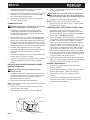
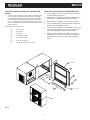
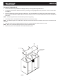
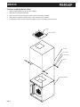
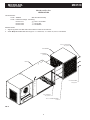
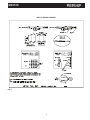
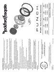
MICRO-AIR AIR CLEANER
INSTALLATION AND OPERATION MANUAL
MX3510
Includes Installation, Operation, and Service Instructions
CAUTION
Read complete instructions before operating.
Please file for future reference.
MICRO AIR
CLEAN AIR SYSTEMS
MX3510
®
MODEL MX 3510 SPECIFICATIONS
ELECTRICAL CONNECTIONS
Input volts:
1.
120/208-230/460/575v, 60Hz
Max current: 20 Amps (at 120V, 1 1⁄2 HP, single phase)
5.2 Amps (at 208-230V, 1 1⁄2 HP, 3 phase)
2.6 Amps (at 460V, 1 1⁄2 HP, 3 phase)
6.8 Amps (at 208-230V 2 HP, 3 phase)
3.4 Amps (at 460V, 2 HP,3 phase)
9.6 Amps (at 208-230V, 3 HP, 3 phase)
4.8 Amps (at 460V,3 HP, 3 phase)
3.9 Amps (at 575V, 3 HP,3 phase)
Motor:
! CAUTION: Be sure that the designated circuit breaker
is off until all wiring has been completed.
NOTE: It is recommended that a properly sized motor starter /
protector be used in the supply circuit for 208-240V/460V/575V
units. 120V units have thermally protected motors with on/off
switches.
1 1⁄2 HP TEFC
2 HP TEFC
3 HP TEFC
Dimensions: 26” h X 26”w X 69”l
2.
Make electrical connections as shown in wiring diagram to
the wires protruding form the conduit on the side of the unit.
3.
Check blower for proper rotation direction. Blower should
rotate clockwise when viewed from the pulley end. If the
blower rotates backwards, interchange two of the motor
supply connections.
4.
Check current draw of motor. Do not exceed Amps
specified.
Shipping Wt: 300lbs
Actual Wt:
Conduit electrical connections should be made by a
qualified electrician, and must comply with local electrical
codes.
268lb*
* Add 35lbs. per charcoal module as option
PACKAGE CONTENTS
PRE-OPERATION CHECKLIST
1 Ea. MX3510 Unit
1 Ea. Owners Manual
4 Ea. 5/16” X 18” Eye Bolt
4 Ea. 5/16” Hex Nut
Before placing unit in service, check the following items:
•
Check blower drive belt for proper tension. (Belt should
deflect approximately 3⁄4” when firm pressure is applied
midway between the pulleys.)
PRE-OPERATING INSTRUCTIONS
1.
After removing the cardboard packing and plastic wrap
from the unit, lay the unit down in a horizontal position.
•
Check that motor, blower, and drive pulleys are mounted
securely.
2.
Unbolt the skid from the unit. Discard skid and hardware.
•
Make sure that both corners of every pocket in the filter bag
is supported by the filter support rods and that filter support
rods are fully engaged in their support brackets.
•
Air flow direction arrows on the pre-filters must point toward
the blower.
•
Make sure that all access panels, removed during
installation, are replaced and the filter access door is
closed.
HANGING INSTRUCTIONS
1.
Remove the hanger kit from the owners Manual envelope
which contains four (4) threaded eyebolts and hex nuts.
2.
Thread a nut onto each eyebolt and thread an eyebolt into
each of the four (4) threaded holes in the cabinet. Tighten
nuts against the cabinet. The unit is now ready to be hung
in an appropriate location.
Unit is now ready to be placed in service.
NOTE: If hanging MX 3510 upside down is required, remove
the four (4) 5/16” hex bolts from the bottom of cabinet and
relocate to top four corners. Then place the four (4) eye bolts
into bottom panel of cabinet.
2.
AIR FLOW ADJUSTMENT
The MX 3510 is equipped with variable diameter pulleys on
the motor and blower to allow the air flow to be adjusted to the
installation requirements. The pulleys are set for maximum air
flow at the factory. The air flow rate can be reduced as follows:
Once eye bolts are secured, the MX 3510 is ready to be
hung in an appropriate location. (See FIG. 1)
! CAUTION: Use strong braided wire or chain to support
the aircleaner. Hang from structural supports.
NOTE: If a unit is to be installed on brackets against a wall,
use brackets strong enough to hold the unit. Install brackets
securely into the wall.
1.
Remove motor compartment access cover. Be careful to
avoid tearing gasket material between door and cabinet.
2.
Remove belt.
3.
Loosen pulley adjustment set screw on motor pulley and
screw adjustable shive out away from fixed shive. Tighten
set screw onto flat of fixed screw (See FIG. 2).
INCREASE
DIAMETER
NOTE: CHAIN LINK OR CABLE. SHOULD
HANG VERTICALLY. 15° IS RECOMMENDED
MAX. ANGLE FROM VERTICAL.
DECREASE
DIAMETER
SET SCREW TO
SET DESIRED O.D.
FIXED SHIVE
EYE-BOLTS &
HEX NUTS ARE
SUPPLIED.
FIG. 1
2
FIG. 2
ADJUSTABLE SHIVE - ROTATE BY 1/2 TURN INCREMENTS
TO TIGHTEN SET SCREW AGAINST FLATS.
MX3510
MICRO AIR
CLEAN AIR SYSTEMS
4.
Adjusting the motor pulley may require a size larger or
smaller belt, depending on the application.
5.
Replace belt and check belt tension. Proper tension should
be between 1⁄2” and 3⁄4” deflection when belt is squeezed
with normal pressure between fingers.
6.
5.
®
Using 15⁄16” hex bolts and washers re-secure motor/blower
module with filter module.
! CAUTION: Due to relocation of internal components,
some wiring may be loose. Be sure to retain wires so
they will not become loose in air stream of blower inlet.
Replace motor compartment access cover. Recheck for
correct current draw of motor.
6.
Reinstall motor access door and exhaust grille.
NOTE: Care is required to protect blower outlet gasket.
CHANGING FILTERS
7.
! CAUTION: Always make sure that the unit is turned off
Reconnect input power and turn unit on. Check for proper
air flow and blower rotations
before changing filters or servicing the unit.
PRESSURE SWITCH ADJUSTMENT INSTRUCTIONS
1.
The MX3510 is equipped with a filter change light or
optional Magnehelic Gauge. If the differential pressure
has been set properly, the light or gauge signals the need
for examination of the filters.
1.
The pressure switch which turns the light on with a
differential pressure increase, should be wired to poles L1
(red) and L2 (blue) at the time of installation with 208/230/
460 volt source. (See Wiring Diagram.)
2.
When the light comes on, or gauge reads high differential
pressure, turn the unit off and remove the pre-filter only.
Replace with a new pre-filter, making sure that the air flow
directional arrow is pointed toward the outlet end. Turn the
unit back on. If the filter change light is off, or gauge reads
low differential pressure, then the unit is operating properly.
2.
3.
If the filter change light fails to go out, or the gauge
continues to read high differential pressure after replacing
the pre-filter, then the media filter also needs to be
replaced.
4.
To install a new bag filter, turn the unit off. Remove the filter
from the channel and insert a new filter.
The pressure switch is preset at the factory to indicate (light
on) dirty filters, but may need readjustment due to a desire
for earlier or later filter changes, a different combination
of filters, or because the set point shifted during shipping.
The pressure switch is also orientation sensitive. To
readjust the switch, remove the hole plug in the side of the
unit for access to the adjustment screw. Make sure filters
and pre-filters are installed in unit. Turn the unit on and
place a piece of cardboard over the intake covering about
80 to 85% of the intake area. With a standard screwdriver,
turn the adjustment screw clockwise until the light goes off,
or counterclockwise until the light comes on.
5.
Start the unit. The filter change light should be off, or gauge
reads low differential pressure and the unit operating
properly.
3.
For more time between filter changes (less air flow), cover
slightly more of the opening, and for less time between filter
changes (more air flow), cover less of the opening.
GENERAL MAINTENANCE
INSTRUCTIONS FOR SIDE DISCHARGE BLOWER
EXHAUST ON MX 3510
! CAUTION: Read instructions completely before
making changes.
1.
2.
The MX3510 moto/blower module can be rotated so that
exhaust air exits from the side of the unit. Before rotating
motor/blower module be sure that all input power is
disconnected and unit is turned off.
Remove motor access door and exhaust grille.
NOTE: Care is required when removing the panel to protect the
blower outlet gasket.
3.
Remove 15⁄16” hex bolts and washers that secure motor/
blower module to filter module.
4.
Rotate motor/blower module 90° as shown in FIG. 3.
MOTOR ACCESS
DOOR
FILTER MODULE
FILTER DOOR
FIG. 3
BLOWER MODULE
3
1.
Occasionally check the condition of the drive belt for
tightness and wear.
2.
Check the blower bearings for unusual war and the blower
wheel for debris and dirt. Clean when necessary.
3.
Check the wiring for loose connections or cracked
insulation.
4.
No lubrication is required for the motor because it is a
permanent pre-lube design. Excessive dirt and or oil
should be removed periodically.
MICRO AIR
CLEAN AIR SYSTEMS
MX3510
®
UNITS WITH HEPA OR CHARCOAL OPTIONS FOR
MX3510
1.
HEPA OR CHARCOAL AS SECOND MAIN FILTER
On units with optional HEPA or charcoal filters, an adjustable filter
track kit is used to complete the seal of these filters to the filter
stop (See FIG. 4 & 5). If the unit was ordered with either a HEPA
or charcoal filter, this adjustable filter track kit was included with
the unit. If a HEPA or charcoal filter is ordered as an after-market
item, the adjustable filer track kit should be ordered as well. Order
Part No. 38036-01.
Each filter track kit is supplied with:
j
k
l
m
n
o
p
1pc. Filter track
2pc. Supports
1pc. Handle
1.
Place supports k in cabinet at a dimension of 13 1⁄4” and
secure with self tapping screw.
2.
Place track j in cabinet so it rests upon supports and 1⁄2”
diameter pin is located behind brackets on supports.
3.
Place handle l on supports so that it rests in notches.
4.
Lock 1⁄2” diameter rods on handle and track in place with
brackets m and self tapping screws.
5.
Place handle stop bracket n at a dimension of 15 1⁄2” and
secure with self tapping screws. This is to keep handle
from rotating past 90° and allowing filter to loosen.
6.
Place horizontal supports o in 2 places. One piece at
a dimension of 5” on bottom of cabinet and one piece at
a dimension of 10” on rear of cabinet with self tapping
screws.
4pc. Retaining brackets
1pc. Door stop bracket
3pc. Horizontal support
16pc. #8-32 self tapping hex screws.
6
2
TYP. 2 PLCS.
1
3
13”
10”
5
5”
6
RCM
FIG. 4
4
4
TYP. 4 PLCS.
MX3510
MICRO AIR
CLEAN AIR SYSTEMS
®
HEPA OR CHARCOAL AS FIRST AND SECOND MAIN FILTERS
1.
Place supports k in cabinet at a dimension of 24 15⁄16” and secure with self tapping screws.
2.
Place track j in cabinet so it rests upon supports and 1⁄2” diameter pin is located behind brackets on supports.
3.
Place handle l on supports so that it rests in notches.
4.
Lock 1⁄2” diameter rods on handle and track in place with brackets m and self tapping screws.
5.
Place handle stop bracket n at dimension of 27” and secure with self tapping screws. This is to keep handle from rotating
past 90° and allowing filter to loosen.
6.
Place Horizontal supports o 1pc. on rear of cabinet at a dimension of 9”, o 1pc. on bottom of cabinet at 5” and o 1pc. on
bottom of cabinet at 12 3⁄4” and secure with self tapping screws.
2
TYP. 2 PLCS.
1
6
3
9”
5
24 5/8”
12 3/4”
5”
4
6
RCM
FIG. 5
5
TYP. 4 PLCS.
MICRO AIR
CLEAN AIR SYSTEMS
MX3510
®
FILLING OF RCM MODULES
1.
Remove bulk charcoal or purasorb from shipping carton by removing plastic bags within carton.
2.
set module on level surface. Remove fill cover by removing six 10-32 phillip head screws, that secure cover. Set cover aside
(See FIG. 6).
3.
Open the plastic bag by removing the tape, holding close. Pour the material from the plastic bag into the module through the
slots. It may be necessary to slightly shake the module to assure an even fill. Excess material may be saved by resealing the
plastic bag.
NOTE: Slow pouring will minimize dust that will be present during pouring.
4.
After filling module, discard plastic bag and reinstall fill cover removed in step 2.
NOTE: The MX3510 requires two modules when used as a second main filter and four modules when used as a first and second
main filter.
5.
With Filter track in place and handle pulled out away from cabinet load RCM / HEPA modules into track.
NOTE: Make sure modules are seated properly into track and stacked evenly.
6.
With filters in place rotate handle 90° and lock filter modules in place.
FILL COVER
POUR MATERIAL
INTO SLOTS
FIG. 6
6
MX3510
MICRO AIR
CLEAN AIR SYSTEMS
OPTIONAL SILENCER INSTALLATION
1.
Remove Exhaust Grille from unit as shown in FIG. 7.
2.
Slide Silencer over Blower Assembly.
3.
Align holes from Silencer with those located on sides of the Blower Assembly.
4.
Attach Silencer to Blower Assembly using 3⁄8” bolt, lockwasher, & flat washer.
5.
Center Exhaust Grille over hole in Silencer & attach using 8-32 self tapping machine screws.
8-32 SMS
EXHAUST GRILLE
SILENCER
FLAT WASHER
LOCK WASHER
3/8” BOLT
BLOWER ASSEMBLY
FIG. 7
7
®
MICRO AIR
CLEAN AIR SYSTEMS
MX3510
®
Wrap Around Pre-filter
INSTALLATION
This Kit Includes:
1 Each 38086-01
WAP Pre-filter Assembly
1 Each Hardware Package - Containing:
15 ”
6 Each P114
⁄16 -18 X 0.75 Hex Bolt
15 ”
6 Each P222
⁄16 -18 Hex Nut
6 Each P233
15
⁄16” Flat Washer
INSTALLATION:
1.
Align six (6) holes from WAP with holes located on bottom of Air Filter Unit.
2.
Attach Wrap Around Pre-filter with six (6) ea. 15⁄16”-18 hex bolt, 15⁄16”-18 hex nut, and 15⁄16” flat washer.
5/16”X.75” HEX BOLTS
TYP. (6) PLCS.
WAP ASSEMBLY
FILTER MEDIA
(3 SIDES)
MX3510
5/16” FLAT WASHER
TYP. (6) PLCS.
5/16”-18 HEX NUT
TYP. (6) PLCS.
1/8” X 1/4” ADHESIVE BACKED
FOAM
FIG. 8
8
MX3510
MICRO AIR
CLEAN AIR SYSTEMS
MX3510 WIRING DIAGRAM
FIG. 9
9
®
MICRO AIR
CLEAN AIR SYSTEMS
MX3510
®
MX3510 PARTS LIST
5
14
10
13
4
6
2
12
3
9
1
11
8
7
ITEM
PART NO.
1.
P1977
2.
38010-01
3.
DESCRIPTION
ITEM
PART NO.
10.
P3545
1 1/2 HP, 115V, 1 Phase Motor
ITEM
PART NO.
12.
P1710
Blower Access Panel
P3546
4.95” Blower Pulley
1 1/2 HP, 208-230/460V, 3 Phase Motor
P1974
P1429
Light (120V)
5.93” Blower Pulley
P1966
2 HP, 208-230/460V, 3 Phase Motor
P1711
P1481
6.93” Blower Pulley
Light (208-230V, 460V, 575V)
P3495
3 HP, 208-230/460V, 3 Phase Motor
P3218
4.
P3505
7.93” Blower Pulley
Pressure Switch
P2813
3 HP, 575V, 3 Phase Motor
P3183
5.
38072-01
9.95” Blower Pulley
P1495
42” Belt
P3540
6.
P1372
12.00” Blower Pulley
Latch (2 ea, required)
P3207
43” Belt
13.
P3498
7.
Blower (Standard)
38011-02
Motor Access Panel
P3182
44” Belt
14.
P3214
Filter Gasket (Specify Length)
8.
38043-01
Filter Door
P3198
45” Belt
NOT SHOWN
38059-01
SCM W/ 3 - 8” Collars
9.
P2105
1 1/2 HP, 5/8” Shaft, Motor Pulley
P3213
46” Belt
NOT SHOWN
38059-02
SCM W/ 2 - 10” Collars
P3578
2 HP, 5/8” Shaft, Motor Pulley
P3195
47” Belt
NOT SHOWN
38059-03
SCM W/ 1 - 16” Collar
P3579
2 HP, 7/8” Shaft, Motor Pulley
P3548
48” Belt
NOT SHOWN
P2250
P2140
3 HP, 7/8” Shaft, Motor Pulley
P3550
49” Belt
NOT SHOWN
38086-01
Wrap Around Pre-Filter
P3549
52” Belt
NOT SHOWN
38050-01
Silencer
NOT SHOWN
38036-01
Filter Track
Grille
Cabinet Weldment
11.
DESCRIPTION
10
DESCRIPTION
Magnahelic Gauge
MX3510
MICRO AIR
NOTES:
11
CLEAN AIR SYSTEMS
®
MICRO AIR
CLEAN AIR SYSTEMS
MX3510
®
TROUBLESHOOTING CHART
! CAUTION:
Before disassembling the unit or doing any inspection of the parts, make certain that the power has been cut
off and the blower has come to a complete stop. Never run the unit with the access door open or removed.
Problem
Unit Fails to Start
Possible Cause
Dead power line
Blown fuse
Loose wire in terminal box
Burned out motor
Remedy
Check the Circuit and Switch
Replace Fuse
Reconnect Wire
Replace Motor
Unit Runs Slowly or
Inadequate Capture Velocity
Wired for wrong voltage
or improper rotation
Dirty filters
Check input voltage
Check wiring diagram
Service filters
(See Changing Filters Section)
Reach into hood and
Remove obstruction
Adjust or change pulleys
Obstruction in hose/arm
assembly
Pulleys set for static
Vibration
Loose mounting bolts
Foreign objects in blower
Dirty disposable filters
Obstruction in hose/arm
assembly
Mist Coming from Exhaust
P1411
P1586
P1799
P1439
P2179
P1455
P1456
P1460
33740-01
33740-02
38086-01
Dirty disposable filters or torn filters
air bypass around filters
REPLACEMENT FILTER LIST
Tighten bolts
Remove access door and
remove objects
Service filters
Reach into hood and
remove obstruction
Replace filters
Check for proper seal against
picture frame and seals on door
& back wall.
24” X 24” X 4“
Pleated Pre-Filter
P1585
24” X 24” X 2”
24” X 24” X 2”
96% Washable Pre-Filter
P1475
24” X 24” X 2”
24” X 24” X 2”
Baffle Oil Impinger
P1461
24” X 24” X 2”
NOTE: 2” Pre-Filters must be used in combinations to fill 4” channel.
24” X 24” X 32”
55% Bag Filter
P1442
24” X 24” X 32”
24” X 24” X 32”
95% Oil Mist Bag with Loops
P2104
24” X 24” X 32”
24” X 24” X 12”
95% DOP HEPA
P2101
24” X 24” X 12”
24” X 24” X 12”
Disposable Charcoal Filter
24” X 24” X 15”
Short 95% Bag (For use with HEPA or Charcoal Filters)
70% Washable Pre-Filter
Mesh Oil Impinger
Pleated Pre-Filter
95% Bag Filter
Duo Cube Bag
99.97% DOP HEPA
Refillable Charcoal Module
Refillable Purasorb Module
Wrap Around Pre-Filter Module
AIR CLEANERS
Litho in U.S.A.
Products of Metal_Fab. Inc.
P.O. Box 1138 • Wichtia, Ks 67201
(316) 943-2351 • FAX (316) 943-2717
12
© 2003 Metal-Fab, Inc.
Form No. L1469 03/03
7166