1
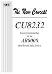
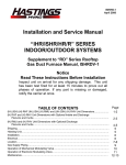
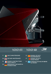
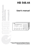
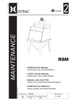
Technical Information
FR - FC - FCO - FCR
Models100÷800
FR - FC - FCO - FCR 100÷800
Fan coil units series
FAN COIL UNITS
SERIES FR - FC - FCO - FCR
Models 100-200-300-400-600-800
Technical details
This manual is in three sections:
- SECTION A - GENERAL INFORMATION
Contains descriptions and technical details of the equipment.
- SECTION B - INSTALLATION DETAILS FOR THE INSTALLER
Contains all the instructions and notes necessary for installing equipment.
- SECTION C - USER INSTRUCTION AND MAINTENANCE MANUAL
This section is for the user's use and contains all the necessary information for the correct usage and
periodic checks on the equipment.
Important notes for using the manual:
1 - To ensure correct and safe use of the appliance, the planner, installer, user and maintenance
technician respectively must scrupulously observe everything contained in this manual. The
manual must be held for reference and must be kept with the appliance for the length of its working
life, including in the case of its transfer to a third party.
2 - The word WARNING! indicates information of great importance which must be strictly observed.
Non- compliance with this instruction could result in damage to the appliance and/or danger in using
it. Paragraphs written in bold contain important information, advice or instructions which must be
carefully considered.
3 - Accorroni S.r.l. is not responsible for any damage caused by the improper use of the appliance, by
any use different from the one designated or by any incomplete or approximate conformation to the
instructions in this manual.
4 - The technical data, physical appearance, components and accessories shown in this manual may
be subject to change. Accorroni S.r.l. reserves the right to make any changes at any time that it
considers necessary for improving the quality of the product.
5 - References to laws, norms and technical regulations in the manual are for information purposes
only and are valid at the date of printing shown on the last page. Accorroni S.r.l. has no responsibility
to third parties arising out of implementation of new provisions or changes to existing ones.
6 - Accorroni S.r.l. is responsible for ensuring that the product conforms to the production laws,
regulations and norms in force at the time of putting the product on the market. Knowledge and
observance of the laws and regulations appropriate to the plant design, installation, use and
maintenance of the appliance are the exclusive responsibility of the planner, installer and user
respectively.
INDEX
SECTION A - GENERAL INFORMATION
1.
1.1
1.2
1.3
1.4
1.5
1.6
page
PRINCIPAL CHARACTERISTICS ......................................................................................... 3
Appliance classification ........................................................................................................... 3
EC conformity ......................................................................................................................... 3
Functional description ............................................................................................................. 3
Technical characteristics ........................................................................................................ 3
Pack contents ......................................................................................................................... 4
Optional accessories .............................................................................................................. 4
1.7
1.8
1.9
1.10
1.11
1.12
Measurements ........................................................................................................................ 6
Components ........................................................................................................................... 8
Technical data tables ............................................................................................................ 13
Standard 3 row battery heat output diagrams ....................................................................... 14
Standard 3 row battery charge loss for water at 10°C diagrams .......................................... 17
Electrical Diagrams .............................................................................................................. 20
SECTION B - INSTALLATION INSTRUCTIONS
2.
WARNINGS .........................................................................................................................
2.1 Installer qualifications ............................................................................................................
2.2 Preliminary information .........................................................................................................
2.3 Transport and handling .........................................................................................................
2.4 Data control ..........................................................................................................................
2.5 Instruction use.......................................................................................................................
3.
INSTALLATION ....................................................................................................................
3.1 Positioning ............................................................................................................................
3.2 Installation procedures ..........................................................................................................
4.
STARTING UP .....................................................................................................................
4.1 Checks ..................................................................................................................................
4.2 Starting up .............................................................................................................................
5.
REPLACING COMPONENTS .............................................................................................
5.1 Fan group ..............................................................................................................................
5.2 Heat exchanger .....................................................................................................................
22
22
22
22
22
22
23
23
23
25
25
25
26
26
26
SECTION C - USER INSTRUCTION AND MAINTENANCE MANUAL
6.
WARNINGS .........................................................................................................................
6.1 Instructions and guarantee ....................................................................................................
6.2 Recommendations - improper use .......................................................................................
7.
STARTING UP .....................................................................................................................
7.1 Checks ..................................................................................................................................
7.2 Turning on .............................................................................................................................
7.3 Turning off .............................................................................................................................
8.
MAINTENANCE ...................................................................................................................
8.1 Normal user maintenance .....................................................................................................
8.2 Regular checks .....................................................................................................................
8.3 Trouble-shooting ...................................................................................................................
27
27
27
28
28
28
28
28
28
29
29
APPENDICES
EC conformity declaration ..................................................................................................... 30
pag. 2
SECTION A - GENERAL INFORMATION
1. PRINCIPAL CHARACTERISTICS
1.4 ASSEMBLY CHARACTERISTICS
1.1 APPLIANCE CLASSIFICATION
1.4.1 Available versions
The F-FR-FC-FCR fan heaters are defined as
"air treatment terminals for winter and summer
air conditioning".
1.2 EC CONFORMITY - CERTIFICATION
The EC symbol guarantees that the appliance
conforms to EEC machinery directive EEC/98/
37, low tension directive EEC/73/23,
electromagnetic directive EEC/89/336 and any
subsequent amendments. The appliances have
the Eurovent certificates and the symbol
guarantees conformity to the data declared.
1.3 FUNCTIONAL DESCRIPTION
The fan heaters consist essentially of a system
of heat exchange between the liquid circulating
inside the exchanger (hot or cold water) and the
air flow controlled by a fan system. The outside
air is taken in by the fans and sent out to the heat
exchanger which heats the air in winter or cools
it in summer. During the summer cycle,
depending on the heat-hygrometric conditions of
the outside air, water condensation is formed
and collected in the appropriate container so that
it can be disposed of.
The treated air is emitted through the appliance
grille or through the outlet units built in to the plant.
The appliances come as standard with fittings
for 2 pipes. For 4-pipe plants with two independent
circuits, there is an optional supplementary heat
exchange system. The fan heater has a remote
control (supplied separately). A choice can be
made from various available versions.
The fan heaters are available in 6 different sizes
and in the following versions:
FR
- Vertical with casing
For wall installation, under windows or in
any other free space or position which offers
technical or functional advantages.
FC - Horizontal with casing
For direct ceiling installation in all situations
where there is not enough free wall space.
FCO - Vertical built in
Supplied without any casing for invisible
installation in custom made panels and
connection to intake and output grilles and
outlets.
FCR - Horizontal built in
As above, supplied without casing for
invisible installation in panelling or dropped
ceiling.
For the F and FR versions, there is also a G
variation with frontal air intake grille complete
with filter.
1.4.2 Component characteristics
The support frame is made in zinc plate of an
appropriate thickness and comes with fixings
already in place for attaching the appliance to a
wall or ceiling with hooks and brackets as well as
mountings for the various components and
accessories. Internal surfaces are insulated
with closed-cell fireproof material.
The heat exchange system is for a 2-pipe plant
and consists of 3 rows of copper pipes with
continuous aluminium fins. The aluminium fin
pack is welded to the pipe surface by mechanical
expansion of the pipes themselves. The frame
is in stainless steel and the collectors in brass
alloy come with female attaching flanges of G 1/
2" and manual air bleed valves of G1/8". The
fan coil unit come as standard with plumbing
attachments on the left side.
The fan system consists of one (sizes 100 and
200) or two centrifugal double-aspiration fans.
They have a high air capacity and low noise level
with blades and screws in plastic. The system
is electronically balanced before and after being
mounted in the unit.
pag. 3
The single-phase 230 V electric motors have a
permanently installed capacitor and heat
protection is incorporated. Use of the
autotransformer means that 6 speeds can be
accessed. Three are standard and can be
selected from the control panel.
The motor is directly coupled to the fan(s) and
mounted on a flexible support and the system is
assembled to include a tray for collection of
condensation. Electrical connection with the
control panel is by rapid polarised insert.
The air filter is made of synthetic fibre and
mounted on a metal frame with a mesh net on
both sides. It can be extracted using the
unblocking flanges and a tool. In the FC and FCR
versions with casing, the air filter is supplied on
request.
The cover (F and FR versions) is made of zinc
plate and pre-painted in colour RAL 9002. It is
protected by transparent cling film to prevent
damage during transportation and installation. G
version are also available with a cover complete
with frontal intake grille in plastic and air filter.
The air output grille comes in modular form in
heat-resistant plastic in colour RAL 7032. The
right and left terminals include the site for the
control panel (F version) and the necessary
access flaps which have an exclusive trip closing
mechanism. In locations where access to the
control panel is not allowed (public places,
schools etc.) the access points can be closed
using the appropriate screw with head cover.
The F version fan heaters come as standard
with space for the control panel on the right
side.
The control panel is not included in the standard
fan heater pack because there are various different
models both for mounting on the appliance and
for remote mounting on a wall:
- Basic control panel 1
consists of an on-off switch for starting and
turning off the fan heater, a manual 3-speed
selector and an 'on' indicator light.
- Basic control panel 2
consists of a manual selector for OFF/
SUMMER/WINTER, a 3-speed manual selector
and an 'on' indicator light.
The control panel is set up for connection of a
thermostat (supplied separately) which means
that in the heating mode the fan is activated
only when the temperature of the water in the
heat exchanger exceeds a pre-set limit.
pag. 4
- Electronic thermostat 1
consists of an on-off switch for starting and
turning off the fan heater, a 3-speed manual
selector, and 'on' indicator light and a manual
SUMMER/WINTER selector.
The thermostat ensures automatic accurate
temperature control in heating and conditioning
plants with 2 pipes. The thermostat regulator
switch enables temperatures of from 5°C to
35°C to be programmed. The fan heater goes
off automatically when the desired temperature is reached.
- Electronic thermostat 2
consists of a manual OFF/SUMMER/WINTER
switch, a 3-speed manual selector and an 'on'
indicator light.
The thermostat includes all the functions of
electronic thermostat 1 and in addition can be
used with a 2-electrovalve control in 4-pipe
plants or 1 electrical resistance electrovalve
in 2-pipe plants. A minimum temperature
reading can also be included using an
appropriate connection (for use in winter
cycle).
- Microprocessor thermostat
Includes all the functions of the electronic
thermostats and in addition has automatic fan
speed selection and summer/winter switch. A
2 electrovalve control is possible in 4-pipe
plants and 1 electrical resistance electrovalve
in 2-pipe plants. A minimum temperature
reading can also be included (for winter use)
and a device for activating the energy saving
function.
1.5 PACK CONTENTS
The fan heaters are supplied as standard in
recyclable cardboard packaging with expanded
polystyrene or pre-shaped cardboard protective
covering.
The pack contains this manual of technical
installation procedures, use and maintenance
as well as plastic fittings and screws for fixing
the filters in versions F-FR with covers.
1.6 OPTIONAL ACCESSORIES
As well as the contents listed above, the following
optional extras can be supplied:
- Basic control panel 1 (with bracket for mounting
on the appliance or on the wall).
- Basic control panel 2 (with bracket for mounting
on the appliance or on the wall).
- Electronic thermostat 1 (with bracket for
mounting on the appliance or on the wall).
- 90° air intake system for FC - FCR versions
with casing.
- Electronic thermostat 2 (with bracket for
mounting on the appliance or on the wall).
- 90° air output system for FC - FCR versions
with casing.
- Microprocessor thermostat (with bracket for
mounting on the appliance or on the wall).
- Direct air output system for FC -FCR versions
with casing.
- Mechanical thermostat for base control panel 2.
- Frontal air intake panel for FCR horizontal
version with casing.
- Mechanical thermostat for control panel with
electronic thermostat 1.
- Minimum temperature gauge for control panel
with electronic thermostat 2.
- Lower air intake panel for FCR horizontal
version with casing.
- Lower/back air intake closure panel.
- Minimum temperature gauge for control panel
with microprocessor thermostat.
- Aluminium air intake grille with filter for FC FCR versions with casing.
- 1 row supplementary battery for heating.
- Aluminium air output grille with fixed slats for
FC - FCR versions with casing.
- Auxiliary condensation collection tray for use
with F - FC vertical versions.
- Pair of foot supports for F version with cover.
- Frontal grille support for F-FR versions with
cover.
pag. 5
- Air filter for the built in versions FC - FCR.
- Valve kit for 3 row standard battery only, complete with pipes and fittings.
1.7 SIZE AND MASS
1/2” G entry
144
45
93
274
477
562
360
1/2” G exit
150
220
172
48
C
A
D
B
562
VERTICAL FR VERSION WITH COVER
A
477
D
45
144
220
172 48
274
B
1/2” G exit
1/2” G entry
Fig. 1
HORIZONTAL FC VERSION WITH COVER
Mod.
100
200
300
400
600
800
A
760
870
980
1.090
1.310
1.310
B
440
550
660
770
990
990
C
460
570
680
790
1.010
1.010
D
644
754
864
974
1.194
1.194
pag. 6
1.7 SIZE AND MASS
1/2” G entry
144
45
274
477
525
1/2” G exit
220
142
A
B
VERTICAL FC VERSION WITH CASING
A+60
525
24
477
A
220
118
144
45
274
B
1/2” G exit
1/2” G entry
HORIZONTAL FCR VERSION WITH CASING
Fig. 2
Mod.
100
200
300
400
600
800
A
480
590
700
810
1.030
1.030
B
440
550
660
770
990
990
pag. 7
pag. 8
Fig. 3
1.8 DETAILED VIEW - Vertical FR version with cover
modd. 100-200
pag. 9
Fig. 4
1.8 DETAILED VIEW - Horizontal FC version with cover
modd. 100-200
pag. 10
Fig. 5
1.8 DETAILED VIEW - Vertical FCO version with casing
modd. 100-200
pag. 11
Fig. 6
1.8 DETAILED VIEW - Horizontal FCR version with casing
modd. 100-200
Components
Vertical FR version with cover (fig. 3)
01 cover with grille
02 variation G with frontal air intake grille
03 3 row heat exchange system
04 complete fan system
05 autotransformer
06 standard air filter
07 frontal air intake filter or support
08 fan motor
09 fan casing + fan
10 220mm grille element
11 right front intake grille terminal
12 left front intake grille terminal
13 right grille terminal
14 left grille terminal
15 right flap
16 left flap
17 330mm grille element
Components
Vertical FCO version with casing (fig. 5)
03 3 row heat exchange system
04 complete fan system
05 autotransformer
08 fan motor
09 fan casing + fan
Components
Horizontal FC version with cover (fig. 4)
01 cover with grille
02 variation G with frontal intake grille
03 3 row heat exchange system
04 complete fan system
05 autotransformer
06 standard air filter
07 frontal air intake filter or support
08 fan motor
09 fan casing + fan
10 220mm grille element
11 right front intake grille terminal
12 left front intake grille terminal
13 right grille terminal
14 left grille terminal
15 right flap
16 left flap
17 330mm grille element
Components
Vertical FCR version with casing (fig. 6)
03 3 row heat exchange system
04 complete fan system
05 autotransformer
08 fan motor
09 fan casing + fan
pag. 12
1.9 TECHNICAL DATA TABLE
Heat potential
Unit of mes.
100
200
300
400
600
800
max.
2.830
4.130
5.640
7.050
9.770
12.330
med.
2.530
3.680
5.140
6.290
8.860
11.230
min.
2.220
3.210
4.670
5.230
7.480
10.580
l/h
243
355
485
606
825
1.060
kPa
1,50
3,00
7,30
11,45
23,50
33,00
max.
1.620
2.200
3.370
4.050
5.900
6.060
med.
1.450
1.830
3.070
3.640
5.270
5.610
min.
1.270
1.680
2.790
3.240
4.620
5.090
max.
1,03
2,27
6,45
8,90
22,25
26,50
max.
1.860
2.420
3.380
4.100
5.930
6.530
med.
1.710
2.240
3.160
3.800
5.510
6.270
min.
1.540
2.060
2.970
3.490
4.630
6.070
l/h
160
208
291
352
516
559
kPa
4,50
7,60
16,00
26,50
46,00
51,00
max.
1.150
1.630
2.730
3.110
4.660
5.140
med.
1.030
1.380
2.410
2.880
4.230
4.740
min.
880
1.270
2.190
2.630
3.870
4.360
max.
930
1.320
2.220
2.550
3.640
4.150
med.
830
1.110
1.940
2.180
3.220
3.670
min.
700
995
1.720
1.970
2.850
3.340
l/h
192
275
460
552
790
868
kPa
1,22
2,70
7,65
10,55
26,45
31,00
max.
210
340
450
560
760
1.000
m 3/h med.
180
280
400
485
630
890
min.
150
240
340
434
540
780
W
(incom ing w ater 70°C)
Max water capacity
Max charge loss water 70 °C
Heat potential
(E)
(incom ing w ater 50°C)
Max charge loss water 50 °C (E)
Heat potential for
supplementary 1 row battery
W
kPa
W
1 row battery water capacity
Max charge loss water 1 row battery
Total cooling potential
(E)
Sensitive cooling potential
W
Max cooling water capacity
Max charge loss cooling water (E)
Air capacity
W
(E)
n°
Number of fans
Noise levels
Noise potential
(E)
1
2
max.
30,6
39,5
40,7
42,3
44,7
50,0
dB (A) med.
27,7
34,9
37,4
39,4
41,8
48,1
min.
22,9
31,9
34,2
36,7
37,1
45,5
max.
39,1
48,0
49,2
50,8
53,2
58,5
dB (A) med.
36,2
43,4
45,9
47,9
50,3
56,6
min.
31,4
40,4
42,7
45,2
45,6
54,0
Electric power
230 V / 1 / 50 Hz
W
34
45
58
77
104
123
Max current absorption
A
0,15
0,20
0,25
0,34
0,46
0,59
W eight
kg
17,0
19,0
22,0
24,6
28,8
30,2
Max motor potential
(E)
(E) = Eurovent certified. Data refer to the following working conditions:
Summer cooling: outside air temperature: 27 °C b .s., 19 °C b .u.
W ater temperature: intak e 7 °C, outgoing 12 °C at max speed
W inter heating: outside air temperature: 20 °C
W ater temperature: intak e 70 °C, ∆ T 10 °C at max speed
(with intak e water at 50 °C the same water capacity as for cooling at max speed)
pag. 13
1.10 3 row standard battery potential heat output diagrams
Rese
iche
- M od.
Heatterm
output
- Mod.
100100
Le
del grafico
alla speed.
massima
conoscere
rese
Therese
heattemiche
output figures
in thecorrispondono
graph are for max.
Tovelocità.
calculatePer
output
at otherle
speeds,
alle
altrethe
velocità
moltiplicare
i valori
per i seguenti coefficienti:
multiply
values
by the following
coefficients:
V med 0,87
V min 0,77
4,5
70
Heattermica
output (Kw)
Resa
(kW)
4,0
60
3,5
3,0
50
2,5
40
2,0
30
1,5
20
1,0
0,5
0
100
200
300
400
500
600
700
800
Portata
acqua (l/h)
Water capacity
water – -TTairaria
∆ T = T ingoing
acqua entrante
Heatterm
output
- Mod.
200 200
Rese
iche
- M od.
Le rese
del grafico
allaspeed.
massima
conoscere
le rese
The
heattemiche
output figures
in the corrispondono
graph are for max.
To velocità.
calculatePer
output
at other speeds,
alle altrethe
velocità
i valori
per i seguenti coefficienti:
multiply
valuesmoltiplicare
by the following
coefficients:
V med 0,88
V min 0,79
6,5
70
Resa
(kW)
Heattermica
output (Kw)
5,5
60
4,5
50
3,5
40
2,5
30
1,5
20
0,5
100
200
300
400
500
600
Water
capacity
Portata
acqua (l/h)
(l/h)
water – -TTairaria
∆ T = T ingoing
acqua entrante
pag. 14
700
800
900
1.10 3 row standard battery heat potential diagrams
Heattermiche
output - Mod.
300 300
Rese
- M od.
Le
del grafico
alla massima
conoscere
rese
Therese
heattemiche
output figures
in thecorrispondono
graph are for max.
speed. Tovelocità.
calculatePer
output
at otherlespeeds,
alle
altre
velocità
moltiplicare
i
valori
per
i
seguenti
coefficienti:
multiply the values by the following coefficients:
V med 0,92
V min 0,82
9,0
70
Heattermica
output (Kw)
Resa
(kW)
8,0
7,0
60
6,0
50
5,0
40
4,0
30
3,0
20
2,0
1,0
100
200
300
400
500
600
700
800
900
Water
capacity
Portata
acqua (l/h)
(l/h)
water – -TTairaria
∆ T = TT ingoing
acqua entrante
Heatterm
output
- Mod.
400400
Rese
iche
- M od.
The
heattemiche
output figures
in thecorrispondono
graph are for max.
speed. Tovelocità.
calculatePer
output
at otherlespeeds,
Le rese
del grafico
alla massima
conoscere
rese
multiply
valuesmoltiplicare
by the following
coefficients:
alle altrethe
velocità
i valori
per i seguenti coefficienti:
V med 0,91
V min 0,83
11,0
10,0
70
Resa
(kW)
Heattermica
output (Kw)
9,0
60
8,0
50
7,0
6,0
40
5,0
30
4,0
20
3,0
2,0
200
300
400
500
600
700
Water capacity
(l/h)
Portata
acqua (l/h)
ingoingentrante
water –- T
T airaria
∆ T = TT acqua
pag. 15
800
900
1000
1.10 3 row standard battery heat potential diagrams
Rese
iche
- M 600
od. 600
Heat term
output
- Mod.
Le rese
del grafico
alla speed.
massima
conoscere
rese
The
heattemiche
output figures
in thecorrispondono
graph are for max.
Tovelocità.
calculatePer
output
at otherle
speeds,
alle altrethe
velocità
i valori
per i seguenti coefficienti:
multiply
valuesmoltiplicare
by the following
coefficients:
V med 0,88
V min 0,78
Resa
(kW)
Heattermica
output (Kw)
16,0
14,0
70
12,0
60
10,0
50
8,0
40
6,0
30
4,0
20
2,0
350
450
550
650
750
850
950
1050
Water capacity
(l/h)
Portata
acqua (l/h)
∆ T = T acqua
ingoingentrante
water –-TTair
aria
Rese
iche
- M od.
Heat term
output
- Mod.
800 800
The
heattemiche
output figures
in thecorrispondono
graph are for max.
Tovelocità.
calculatePer
output
at otherle
speeds,
Le rese
del grafico
alla speed.
massima
conoscere
rese
multiply
valuesmoltiplicare
by the following
coefficients:
alle altrethe
velocità
i valori
per i seguenti coefficienti:
V med 0,93
V min 0,86
16,0
70
Resa
(kW)
Heattermica
output (Kw)
14,0
60
12,0
50
10,0
40
8,0
30
6,0
20
4,0
2,0
400
500
600
700
800
Water capacity
(l/h)
Portata
acqua (l/h)
∆ T = TT acqua
ingoingentrante
water –- TT air
aria
pag. 16
900
1000
1100
1.11 Diagrams for standard 3 row battery
charge loss for 10°C water
To calculate charge loss at different
temperatures, multiply by coefficient K
°C
40
50
60
70
80
K
0,88
0,86
0,84
0,82
0,8
FR-FC-FCO-FCR 100
1,7
1,6
1,5
1,4
1,3
∆P [kPa]
1,2
1,1
1
0,9
0,8
0,7
0,6
0,5
0,4
0,3
80
90
100
110
120
130
140
150
160
170
180
190
200
210
220
230
Portata [kg/h]
Capacity
(kg/h)
FR-FC-FCO-FCR 200
3,4
3,2
3
2,8
2,6
∆P [kPa]
2,4
2,2
2
1,8
1,6
1,4
1,2
1
0,8
0,6
120 130 140 150 160 170 180 190 200 210 220 230 240 250 260 270 280 290 300
Portata [kg/h]
Capacity
(kg/h)
pag. 17
1.11 Diagrams for standard 3 row battery
charge loss for 10°C water
To calculate charge loss at different
temperatures, multiply by coefficient K
°C
40
50
60
70
80
K
0,88
0,86
0,84
0,82
0,8
FR-FC-FCO-FCR 300
9
8,5
8
7,5
7
∆P [kPa]
6,5
6
5,5
5
4,5
4
3,5
3
2,5
2
1,5
200
220
240
260
280
300
320
340
360
380
400
420
440
460
480
500
Capacity
(kg/h)
Portata [kg/h]
FR-FC-FCO-FCR 400
14
13
12
11
∆P [kPa]
10
9
8
7
6
5
4
3
2
240 260 280 300 320 340 360 380 400 420 440 460 480 500 520 540 560 580 600
Portata [kg/h]
Capacity
(kg/h)
pag. 18
1.11 Diagrams for standard 3 row battery
charge loss for 10°C water
To calculate charge loss at different
temperatures, multiply by coefficient K
°C
40
50
60
70
80
K
0,88
0,86
0,84
0,82
0,8
FR-FC-FCO-FCR 600
30
28
26
24
∆P [kPa]
22
20
18
16
14
12
10
8
6
4
300
350
400
450
500
550
600
650
700
750
800
850
Portata
Capacity[kg/h]
(kg/h)
FR-FC-FCO-FCR 800
40
38
36
34
32
∆P [kPa]
30
28
26
24
22
20
18
16
14
12
10
500
550
600
650
700
750
800
Portata [kg/h]
Capacity
(kg/h)
pag. 19
850
900
950
1000
1.12 ELECTRICAL LAYOUT
MICROPROCESSOR
THERMOSTAT
BASIC CONTROL PANEL 1
Check
probe
Fan
Environment
probe
See table
for connections
summer/
winter
Hot water
valve
Cold water
valve
BASIC CONTROL
PANEL 2
See table
for connections
OFF
Fan
EST.
INV.
Fan
See table
for connections
COLOURS CODES
ar
az
b
g/v
CODES
gi
A = Autotransformer
gr
C = Control panel
m
M = Terminal board
n
Mv = Fan motor
r
Tc = Thermostat
ro
__ = Standard connections
v
--- = Connections to be made vi
=
=
=
=
=
=
=
=
=
=
=
=
orange
blue
white
yellow/green
yellow
grey
brown
black
pink
red
green
purple
Connections autotransformer terminal board
wire colours Max
speed
Min
modelli
1
2
3
4
5
6
100
Variation for connecting 800 motor
Fig. 7
v
gi
gi
r
300
v
gi
r
400
v
gi
r
600
v
gi
r
200
v
r
WARNING!
Install a sectioning device with contact opening of
at least 3 mm on the appliance and protect the
electrical wiring with 2A - 250 V fuses.
pag. 20
1.12 ELECTRICAL LAYOUT
ELETRONIC THERMOSTAT 1
ON / OFF
Fan
See table
for connections
Summer/Winter
ELETRONIC THERMOSTAT 2
CODES
A = Autotransformer
C = Control panel
M = Terminal board
Mv = Fan motor
Tc = Thermostat
__
= Standard connections
--- = Connections to be made
COLOURS CODES
ar
az
b
g/v
gi
gr
m
n
r
ro
v
vi
= orange
= blue
= white
= yellow/green
= yellow
= grey
= brown
= black
= pink
= red
= green
= purple
Connecting autotransformer terminal board
wire colours Max
speed
Min
modelli
1
2
3
4
5
6
Water thermostat
Outside air thermostat
100
WINTER
OFF
SUMMER
v
gi
gi
r
300
v
gi
r
400
v
gi
r
600
v
gi
r
200
Outside
air gauge
Fan
v
r
Trip
gauge
800 motor variation connection
See table
for connections
Hot water
valve
Cold water
valve
WARNING!
Install a sectioning device with contact opening
of at least 3 mm on the appliance and protect
the electrical wiring with 2A - 250 V fuses.
Fig. 8
pag. 21
SECTION B - TECHNICAL NOTES FOR THE INSTALLER
2. ATTENTION
2.1 2.1 INSTALLER QUALIFICATIONS
WARNING! Both the plumbing and electrical
parts of the installation must be carried out
by specialists, qualified under the terms of
law 46/'90, who can correctly perform the
operations specified in this manual.
2.2 PRELIMINARY INFORMATION
Before starting installation, ensure that the options
chosen and any plans made conform to the current
rules and regulations regarding heat generators
and/or cooling systems for use in the plant.
As examples, the following are some of the
present provisions:
- a technical report must be compiled with regard
to the provisions in force for energy savings in
new buildings. Art. 28 of law 9 of January 1991,
no. 10.
- a plan must be produced for plants in public
buildings using combustible gas with a heat
potential >35 kW (30,000 kcal/h) or for air
conditioning plants with cooling potential>
40,000 frig/h (46.5 kW).
- There must be a check on the installation in
relation to the electrical wiring of locales
according to EIC norms of electrical safety (for
example in places where there is a bath or
shower).
The relevant technical regulations and
legislation are:
- Law 5 March 1990, no. 46 "regulations for
safety of plants", published in G.U. no. 59 of 12/
3/90.
- D.P.R. 6/12/91 no. 447 "Regulating
implementation of law 5 of March 1990, no.
46, with respect to safety of plants", published
in G.U. no. 38 of 15/2/92.
- Regulation UNI-CTI 10344, '93 edition, "Heating
in buildings - energy use calculations".
To ensure conformity with all the above, use
a qualified central heating engineer who can
guarantee correct compliance and execution
of all necessary operations.
2.3 TRANSPORT AND HANDLING
The fan heater comes in a standard cardboard
pack with internal expanded polystyrene or
cardboard protective packing. The pack may be
moved manually or by forklift, taking care to
respect the signs on the cardboard box with their
appropriate symbols.
Where there are multiple packs on pallets, move
with a forklift which is designed for the weight and
size of the pack and do not force or distort the
box. Respect safety regulations while moving
the load.
Place the packs vertically on top of each other up
to the maximum number shown on the packs.
WARNING! Maximum weight for one person
alone to lift is 30 kg.
On taking delivery, ensure that there has been no
visible damage to the pack and/or to the appliance
during transport. Where there is any damage,
make an immediate formal complaint to the
transporter. Do not install appliances damaged
during transport.
Any storage premises must have stable flooring,
must not be damp and must be free from air
pollution (in warehouses prepare flooring
using pallets to support the packs in a dry,
sheltered place). Keep the packs in places
where no-one, even accidentally, can walk on
them or use them to put things on.
2.4 DATA CHECK
Check that the fan heater and its technical
characteristics conform with what was in the
plan or other specifications. The appliance
identification data is on a label in the back of the
unit on the right side of the frame.
2.5 USE OF INSTRUCTIONS
WARNING! When installing or working on
the appliance, follow all the instructions in
this manual. Any changes in connections
and/or any failure to respect the instructions
will immediately nullify the guarantee and
any manufacturer's responsibility.
pag. 22
for horizontal versions FR - FCR (fig. 9).
When using appropriate accessories (for
example, feet or supports) follow the
instructions for mounting them.
3. INSTALLATION
3.1 POSITIONING NOTES
WARNING! The appliances are not designed
for use in industrial processes and/or
installation in places where corrosive or
explosive products are used.
Before proceeding with installation, make sure
that the following conditions apply in the area
where the fan heater is to be installed:
a) that there is a single-phase 230 Volts - 50Hz
electricity supply and that the plumbing
connections correspond to the standard
connections on the left side of the fan heater;
b)that condensation waste pipes can be fitted
efficiently with an adequate slope (minimum
1%) to join up with a siphon connection to the
waste disposal system in the building;
c) that the position allows for the correct
dispersion of air and that air flow is not
obstructed by any obstacles like sills,
furniture, curtains and, on the other hand, that
the air flow does not cause disturbance to
any people present;
d)that the position of the appliance permits
access for maintenance as well as to the
bleed valves attached to the side. Respect
the distances shown in fig. 9. When
installing versions with casing, put in a
removable panel for access to the fan
heater and for its eventual removal.
e)vertical installation units F - FC must be
placed at a height of about 10 cm from the
floor, so that air is collected correctly by the
fan heater. There must be the same distance
between the wall and the back of the appliance
f) when installing horizontally, make sure
that the support surface is of a material
and capacity suitable for supporting the
weight of the appliance. Ensure that the
fixing devices are suitable for keeping
the fan heater stable for a long time.
3.2 INSTALLATION PROCEDURES
WARNING! Put on protective gloves and
clothing before installing the fan heater
(some parts, like the slat system of the heat
exchanger battery, can be sharp). Use
appropriate tools to avoid accidents during
installation.
Take the fan heater out of the packaging,
extracting it from the top of the side shown on
the box and taking off the polystyrene and
cardboard protection.
For units with covers, take away the filter and
take apart the cover (see fig. 10) unscrewing
the two screws (A) under the side doors of the
grille (the right door, standard position for the
control panel, can be opened by pushing and
releasing in the spot where "PUSH" is written,
while the left is fixed with a screw (B). Undo the
two screws (C) which fix the cover to the side
frame supports at the bottom back of the cover
itself.
Lift the cover carefully until the two flanges on
the lower edge free the cover from the sides of
the frame. Put the cover in a safe place or in the
MINIMUM DISTANCES FOR MAINTENANCE - POSITIONING
10 cm
min. 25 cm
Side for plumbing
connections
min. 15 cm
control panel
side
10 cm
VIEW FROM ABOVE
Fig. 9
pag. 23
TAKING THE COVER APART - MODELS FR - FC
A
traces of water may be found under the fan
heater and/or in the room.
Put the plugs in the holes, leaving the screws
loose.
B
It is advisable for two people to lift and
position the fan heater in order to avoid
any possible damage to the wall or to the
appliance.
Lift the fan heater, placing the 4 fixing points on
the screws and screw into place. Turn the
screws sufficiently to ensure safe mounting.
3.2.2 Plumbing connections
C
When connecting entry and exit points it is
advisable to protect and insulate the pipes and
any valves with anti-condensation insulation to
avoid dripping during cooling cycles.
Fig. 10
packaging until the installation is complete.
Ensure that the plumbing and electrical
connections are compatible with those on the
fan heater and with any accessories which are
to be installed.
3.2.1 Mounting the fan heater
Once the position for the appliance has been
established, mark the four holes to be used for
fixing the unit (fig.11). Use plugs (not supplied)
suitable for the type of support surface (solid
brick, cavity wall, panels etc.).
WARNING! To ensure correct drainage of
condensation into the tray, position the
holes and screws in such a way that the fan
heater is slightly inclined towards the
condensation discharge (about 4mm per
metre is advisable). If this is not done,
The attachments on the exchanger are female
1/2" GAS fillets with external hexagon for a size
26 spanner and are shown in fig.12, with
indications of available space.
Make the connections using spanners and
wrenches but without forcing the pipe
attachment.
Once the pipes have been filled, bleed the air
out by using the bleed valves on the collectors,
using a flat screwdriver or a size 8 hexagonal
spanner on the one in the highest position in
the circuit. Close the bleed valves and check
carefully that there have been no losses at the
various junctions.
Connect the condensation disposal to the
appropriate rubber joint (internal diameter
20mm) for vertical units FR - FC or to the
MOUNTING THE APPLIANCE
A
A fixings interaxes
93
360
150
model
mm
100
460
200
570
300
680
400
790
600
1.010
800
1.010
Fig. 11
pag. 24
SPACES FOR PLUMBING ATTACHMENTS (FR -FC)
70
3.2.3 Electricity connection
WARNING! Turn off the power before
connecting to the electricity supply and complete the plumbing connections first and
ensure they are secure.
70
1/2” G entry
Ensure that the electricity supply is 230V - 50Hz
monophase and that there is an earth cable.
The electricity supply, where a fan heater is
mounted, should be protected and controlled
by an adequate load (minimum 3 mm. Contact
opening) omnipolar switch and a 2A - 250V
fuse.
1/2” G exit
182
Condensation disposal
F version
Space for
pipes
Fig. 12
corresponding copper joint (external diameter
19mm) for horizontal FR- FCR units, ensuring
that the joints are sealed with suitable tape.
For vertical versions F - FC, if the
supplementary condensation tray is used,
connect the disposal to the junction at the
bottom of the tray itself.
Pour water slowly into the condensation tray
and ensure that it runs out correctly towards
the disposal without leaving traces or dripping.
Check that there are no cracks in the
condensation disposal pipes or incorrect
sloping.
The fan heaters come without control panels
as there are various types to choose from.
Carry out the mounting operations for the
specific control panel according to the model
chosen and the type of installation (on the
side of the appliance or remote on a wall).
After mounting the control panel, connect the
electricity cable to the appropriate live, neutral
and earth terminals on the fan heater, inserting
the cable through the cable grip and cutting the
wires so that the yellow/green earth wire is
slightly longer than the other two. This precaution
means that if the wires are accidentally
detached, the earth wire is the last to come out
of the terminal (fig. 13).
4. STARTING UP
4.1 CHECKS
4.1.1 Before starting up the fan heater, ensure
that all current rules and regulations have been
followed both with regard to heat generators and
to cooling systems, as well as those applying to
plants, including the fan heaters themselves.
CONNECTING THE ELECTRICITY SUPPLY
Brown
Grey
Blue
4.1.2 Ensure that the monophase 230 V ~ 50 Hz
electricity supply and the earth cable are
connected to the appropriate terminals in the
appliance.
4.1.3 Ensure that water is circulating correctly
and bleed air using the appropriate bleed valves
situated on the collectors of the heat exchange
system.
4.2 SWITCHING ON
Yellow/Green
Brown
Fig. 13
(references to control panel functions are as in
fig. 14).
a) Preparing the fan heater;
- version 1 controls:
put switch (A) in the "ON" position.
If there is one(in the electronic or 2 - pipe
microprocessor thermostats), put the
pag. 25
summer/winter switch (B) in the position
appropriate for the cycle in course (towards
the top = summer, towards the bottom =
winter).
- Version 2 controls:
Put switch (B) in the position appropriate for
= summer,
=
the cycle in course (
winter).
b) If there is one (in the electronic or
microprocessor thermostats), turn the room
temperature thermostat (C) to the required
temperature.
c) Check that the fan is working properly on all
three speeds by using switch (D) and taking
into account any other checking instruments,
for example the trip thermostat.
d) In FR - FC versions take the transparent
film off the cover. Put the cover back on by
inserting the lower flanges on the attachments
on the frame, adjusting the positions and
fixing it with the two screws placed at the
bottom of the grille flaps. Tighten the two
screws which fix the cover to the side frame
brackets at the bottom back of the cover itself
(fig. 10) Put the air filter in position and fix it
with the plastic filter grips which come with
their screws in a bag in the pack.
5. COMPONENT REPLACEMENT
Before inserting the new fan system, check the
state of the internal surface of the heat exchange
system and if necessary clean it.
Put the new fan system in place and repeat the
above operations in reverse.
5.2 HEAT EXCHANGE SYSTEM
Gain access to the interior of the fan heater by
removing the filter, cover and any panelling in the
case of installation in casing.
In horizontal versions FR - FCR, detach the
condensation disposal joint from the tray and take
off the tray itself by undoing the four screws which
fix it to the framework.
Close the locks on the hydraulic attachments or in
some way separate the fan heater from the rest of
the system. Disconnect the hydraulic attachments
from the heat exchanger using spanners or
wrenches and loosen the four screws which fix it
to the framework at the sides. Loosen as much as
possible the four screws which hold the fan system
too, so that the exchanger can be extracted without
damaging the insulation material.
Gently push open the sides of the framework and
extract the exchanger, rotating it so that the pinions
connecting it to the framework also come out.
To insert and connect the new exchanger, repeat
the above operations in reverse.
To replace any of the components listed
below, consult an authorised Technical
Service Centre. For safety and quality
reasons, use only the original manufacturer's
replacement parts.
WARNING! All of the following operations
must be carried out with the fan heater
switched off and disconnected from the
electricity supply.
5.1 FAN SYSTEM
Get access to the fan system by removing the
filter, cover and any panels where the heater is
installed in a casing. For vertical versions F -FC
take the rubber condensation disposal joint off
from under the tray.
Disconnect the electrical wiring terminals from the
electric motor (see electrical diagrams figs. 7-8)
Loosen the four screws which fix the system to
the appliance framework at the sides.
Take out the fan system carefully holding the tray
and taking care not to damage the insulating
material on the side of the framework.
pag. 26
SECTION C - USER INSTRUCTION
AND MAINTENANCE MANUAL
6.2 RECOMMENDATIONS - IMPROPER USE
appliance
- do not leave objects, containers or glasses
containing liquid on the air outlet grille
- do not cover the heater with curtains or
any objects which could partially obstruct
the intake and/or outlet of air
- do not put clothes, cloths or anything to dry
on the heater grille. As well as obstructing
the passage of air, any dripping inside the
appliance could cause electric shock.
WARNING! To ensure correct and safe use
of the fan heater:
- do not use the heater for any purpose
other than that for which it was designed
- do not lean on, jump over or sit on the
- do not remove the cover, the plastic grille
or the panels of the appliance. Inside them
are moving parts under electrical tension
and/or at very high temperatures. Do not
put your hands or other objects near to
6. ATTENTION
6.1 INSTRUCTIONS AND GUARANTEE
For any future reference or consultation,
this manual should be kept along with the
certificate of guarantee. Do not remove for
any reason whatsoever, the identifying label inside
the appliance as the references written on it are
necessary in the case of any repairs.
Version 1
CONTROL PANEL - OPTIONS AVAILABLE
E
A
D
Basic control
Version 1
Version 2
B
E
A
Basic control
Version 2
D
E
C
A
B
D
C
Microprocessor thermostat
Electronic thermostat
Version 1
E
D
B
E
B
D
Electronic thermostat
Version 2
pag. 27
C
Fig. 14
those parts.
- do not remove the filter without first
disconnecting the electricity supply and
allowing the internal parts to cool.
- in places where it is advisable to block
access to the control panel (public places,
schools etc.), the flaps in version F (vertical
with cover) can be blocked using the screws
and screw covers provided.
7. STARTING UP
- Version 1 controls
Turn switch (A) to "OFF"
- Version 2 controls
Turn switch (B) to "OFF"
7.3.2 To turn off the heater for a prolonged period:
a) Stop the heat generator or cooling system in
the plant according to the specific instructions.
b) According to the control panel version in use,
turn switch (A) or (B) to the "OFF" position.
c) Disconnect the electric supply from the heater
switch.
7.1 CHECKS
Before starting up the fan heater, make sure the
installer has fully completed all the necessary
installation procedures.
7.2 SWITCHING ON
7.2.1 (references to control panel functions refer
to fig. 14)
a) check that the electricity supply is properly
connected and proceed as follows:
- Version 1 controls
Turn switch (A) to the "ON" position.
If there is one (on the electronic or
microprocessor thermostats) put the
summer/winter switch (B) in the positions
suitable for the cycle in course (pointing up
= summer, down = winter).
- Version 2 controls
Turn switch (B) to the position suitable for
the cycle in course (
= summer,
=
winter).
b) If there is one (on the electronic or
microprocessor thermostats), turn the air temperature thermostat (C) to the temperature
required. The indicator light (E) will show the
function according to the characteristics of
the different control panels.
c) Select the fan speed using (D). If there is a trip
thermostat (optional extra), the fan will start
up only if the internal water temperature in the
exchanger is higher than a pre-determined
level. In this case, wait until the system is
ready.
e) Consult the specific instructions for the actual
control panel in use to see any additional
characteristics and likewise for any optional
accessories which have been installed.
7.3 SWITCHING OFF
7.3.1 7.3.1 When turning off the fan heater, it is
not necessary to touch the temperature control
if there is one, but to proceed as follows:
d) When the system is not used during periods
when there are low outside temperatures,
ensure there is no risk of pipes freezing up by
consulting the installer.
8. MAINTENANCE
8.1
NORMAL MAINTENANCE
PROCEDURES FOR THE USER
WARNING! Any procedure which is not
explicitly mentioned in this chapter should
be carried out by specialised personnel.
8.1.1 Cleaning external parts
The external parts of the heater should be cleaned
at least every two months, always after
disconnecting the electricity supply. Use a damp
cloth and remove any dust from the air outlet with
a brush. WARNING! Do not use water sprays
to clean the appliance.
Check that the fan is working well and that air is
coming out of the air outlet grille correctly.
8.1.2 Cleaning the filter
The air filter should be cleaned before every
operational season, or, if the fan heater is in a
dusty environment, at least once a month.
WARNING! Always disconnect the heater
from the electricity supply and allow the fan
motor to cool before proceeding to remove
the filter.
The following instructions relate to F - FR versions
with covers. For encased versions with their
appropriate panelling, refer to the system used
by the planner and/or installer.
Loosen and extract the filter by turning the fixing
screws on the plastic filter holders and turning
them outwards.
Clean the filter, preferably with compressed air,
by blowing in the opposite direction from the
intake, or use a vacuum cleaner. If necessary,
pag. 28
wash the filter under running water and wait for it
to dry completely before re-insertion.
If the filter material starts to show signs of wear
after a few periodic cleanings, it should be
replaced to ensure fully effective functioning. Do
not throw the old filter away carelessly, but
dispose of it in an appropriate rubbish
container.
8.3 POSSIBLE PROBLEMS
Any repair operations should be carried out
by qualified personnel.
In the case of breakdown, contact the nearest
Service Centre. The name can be obtained
directly from Accorroni S.r.l - Numero Verde 800017089.
Re-insert the filter ensuring that it is correctly
fixed using the holders.
Before seeking assistance, ensure that:
WARNING! Never use the fan heater without
the filter in place as moving parts or parts
under tension and/or at high temperature
would be accessible, especially to children!
There would also be less protection against
dust both for the fan and for the heat
exchanger with a resulting loss of efficiency
in the appliance.
b) the heat generator, cooling system and
regulatory controls in the plant are all working
normally;
8.2
PERIODIC CHECKS ON THE FAN
HEATER
a) the electricity supply is correctly connected;
c) any controls on the appliance (air temperature thermostat, trip thermostat, etc.) are
working normally;
d) there are no obstructions to either air intake or
outlet flow.
In order to reduce possible problems to the
minimum and to keep the fan heater in perfect
working order, thus ensuring maximum efficiency
at the lowest costs, it is advisable to have a
general check carried out by a specialist at
the start of every season of functioning. This
check should include cleaning the heat exchange
system, the fan, the filter and the condensation
tray. The latter should be thoroughly cleaned to
avoid formation of mould or other bacteria where
there is stagnant water.
pag. 29
DECLARATION OF CONFORMITY
Manufacturer:
ACCORRONI S.r.l.
Address:
60027 Osimo (AN) - Via Pignocco, 25
Tel. 071/723991 - Fax 071/7133153
Appliances:
Fan Heaters - units for temperature control
Series/Types:
FR - FC - FCO - FCR
Models:
100 - 200 - 300 - 400 - 600 - 800
With reference to the above appliances, Accorroni S.r.l.
DECLARES
that these products
- conform to the 98/37EEC directive regarding machinery
- and also conform to the following directives: EEC/89/336 for electromagnetic compatibility,
EEC73/23 for low tension and any amendments to them as in directive EEC93/68.
Osimo, January 2000
ACCORRONI S.r.l.
Legal representative
Leoni Luciano
pag. 30
pag. 31
Fan coil units series FR - FC - FCO - FCR - Technical details
Cod. 26209501 IT - Rev. 1 - 07/04/03