1
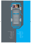
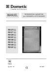
CAUTION!
Provide a 16 A fuse to protect on−board 12 V
circuit.
In order to ensure that the 12V power supply is
shut off when stopping the engine (otherwise the
battery would discharge within a few hours),
perform the power supply to the heating element
(connection A/B in wiring diagram) in a way to
have the 12V supply only live while the vehicle
ignition is switched on.
The connection C/D (interior light, electronics,
cable black / violet) must be permanently provi−
ded by a 12V DC power supply to be protected
by a 2A fuse.
CAUTION!
If the appliance is installed in a caravan
the respective leads for the 12V+ and
12V- connections A/B and C/D must not
be connected to each other on the caravan-side .
1.10.3 Terminal strip
Connections :
on the appliance
-
+
D+ S+ -
A = Ground heating element DC
B = Positive connection, heating element DC
C = Ground electronics
D = Positive connection, electronics
+
D+ = Alternator signal
S+ = AES input signal from solar charge
regulator
A B
C D
on the vehicle
Fig. E31
For MES and AES it is compulsory to provide a permanent 12V DC supply at the terminals C/D (permanent voltage supply for functional electronics).
1.10.4 D+ and solar connection (only for AES models)
D+ − connection :
In >Automatic Mode< the AES electronic
system automatically selects the most efficient
energy supply. In automatic mode the electronic
system uses the D+ signal (dynamo +) of the
alternator to detect 12V DC. 12V DC operation
is selected only while the engine is running in
order to prevent battery discharge.
on the appliance
D+ S+
on the vehicle
Fig. E32
16