1
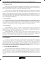
Digital Audio Products 4.24C 24 Bit Digital Crossover and System Processor Operating Manual A S H LY A U D I O I N C . 8 4 7 H o l t R o a d Webster, N Y 1 4 5 8 0 - 9 1 0 3 P h o n e : ( 5 8 5 ) 8 7 2 - 0 0 1 0 Toll-Fre e : ( 8 0 0 ) 8 2 8 - 6 3 0 8 F a x : ( 5 8 5 ) 8 7 2 - 0 7 3 9 w w w. a s h l y. c o m Operating Manual - PROTEA SYSTEM II 4.24C Crossover / System Processor Table Of Contents 2 1 INTRODUCTION . . . . . . . . . . . . . . . . . . . . . . . . . . . . . . . . . . . . . . . . . . . . . . . . . 4 1.1 Audio Features . . . . . . . . . . . . . . . . . . . . . . . . . . . . . . . . . . . . . . . . . . . . . . . . . . 4 1.2 User Interface . . . . . . . . . . . . . . . . . . . . . . . . . . . . . . . . . . . . . . . . . . . . . . . . . . . 4 2 UNPACKING . . . . . . . . . . . . . . . . . . . . . . . . . . . . . . . . . . . . . . . . . . . . . . . . . . . . . . 4 3 AC POWER REQUIREMENTS . . . . . . . . . . . . . . . . . . . . . . . . . . . . . . . . . . . . . 4 4 FRONT PANEL CONTROL FEATURES . . . . . . . . . . . . . . . . . . . . . . . . . . . . 5 4.1 Function Keys and Data Wheel . . . . . . . . . . . . . . . . . . . . . . . . . . . . . . . . . . . . . 5 4.2 Presets . . . . . . . . . . . . . . . . . . . . . . . . . . . . . . . . . . . . . . . . . . . . . . . . . . . . . . . . . 5 4.3 Input Select . . . . . . . . . . . . . . . . . . . . . . . . . . . . . . . . . . . . . . . . . . . . . . . . . . . . . 5 4.4 Output Select . . . . . . . . . . . . . . . . . . . . . . . . . . . . . . . . . . . . . . . . . . . . . . . . . . . . 5 4.5 LED Indicators . . . . . . . . . . . . . . . . . . . . . . . . . . . . . . . . . . . . . . . . . . . . . . . . . . 5 4.6 Audio Functions . . . . . . . . . . . . . . . . . . . . . . . . . . . . . . . . . . . . . . . . . . . . . . . . . 6 4.6a Gain . . . . . . . . . . . . . . . . . . . . . . . . . . . . . . . . . . . . . . . . . . . . . . . . . . . . . . . 6 4.6b EQ . . . . . . . . . . . . . . . . . . . . . . . . . . . . . . . . . . . . . . . . . . . . . . . . . . . . . . . . . 6 4.6c Delay. . . . . . . . . . . . . . . . . . . . . . . . . . . . . . . . . . . . . . . . . . . . . . . . . . . . . . . 7 4.6d Crossover . . . . . . . . . . . . . . . . . . . . . . . . . . . . . . . . . . . . . . . . . . . . . . . . . . . 8 4.6e Limit . . . . . . . . . . . . . . . . . . . . . . . . . . . . . . . . . . . . . . . . . . . . . . . . . . . . . . 10 4.7 Other Functions . . . . . . . . . . . . . . . . . . . . . . . . . . . . . . . . . . . . . . . . . . . . . . . . . 10 4.7a Recall . . . . . . . . . . . . . . . . . . . . . . . . . . . . . . . . . . . . . . . . . . . . . . . . . . . . . 10 4.7b Save . . . . . . . . . . . . . . . . . . . . . . . . . . . . . . . . . . . . . . . . . . . . . . . . . . . . . . 11 4.7c Copy . . . . . . . . . . . . . . . . . . . . . . . . . . . . . . . . . . . . . . . . . . . . . . . . . . . . . . 11 4.7d Mute . . . . . . . . . . . . . . . . . . . . . . . . . . . . . . . . . . . . . . . . . . . . . . . . . . . . . . 11 4.7e Utilities . . . . . . . . . . . . . . . . . . . . . . . . . . . . . . . . . . . . . . . . . . . . . . . . . . . . 11 4.7f Factory Reset . . . . . . . . . . . . . . . . . . . . . . . . . . . . . . . . . . . . . . . . . . . . . . . 12 5 INTERCONNECT FEATURES . . . . . . . . . . . . . . . . . . . . . . . . . . . . . . . . . . . . . 5.1 Audio Connections . . . . . . . . . . . . . . . . . . . . . . . . . . . . . . . . . . . . . . . . . . . . . . 5.2 MIDI Connection . . . . . . . . . . . . . . . . . . . . . . . . . . . . . . . . . . . . . . . . . . . . . . . 5.3 RS-232 Data Connections . . . . . . . . . . . . . . . . . . . . . . . . . . . . . . . . . . . . . . . . 12 12 13 13 Operating Manual - PROTEA SYSTEM II 4.24C Crossover / System Processor 6 PROTEA SYSTEM SOFTWARE . . . . . . . . . . . . . . . . . . . . . . . . . . . . . . . . . . . 6.1 How to Get Protea System Software . . . . . . . . . . . . . . . . . . . . . . . . . . . . . . . . 6.2 Installing Protea System Software. . . . . . . . . . . . . . . . . . . . . . . . . . . . . . . . . . 6.3 Connecting the 4.24C to a Computer . . . . . . . . . . . . . . . . . . . . . . . . . . . . . . . 14 14 14 14 7 TROUBLESHOOTING . . . . . . . . . . . . . . . . . . . . . . . . . . . . . . . . . . . . . . . . . . . . 15 7.1 Audio Troubleshooting Tips . . . . . . . . . . . . . . . . . . . . . . . . . . . . . . . . . . . . . . . 15 7.2 RS-232/MIDI Troubleshooting Tips . . . . . . . . . . . . . . . . . . . . . . . . . . . . . . . . 15 8 SPECIFICATIONS . . . . . . . . . . . . . . . . . . . . . . . . . . . . . . . . . . . . . . . . . . . . . . . . 16 9 DIMENSIONS . . . . . . . . . . . . . . . . . . . . . . . . . . . . . . . . . . . . . . . . . . . . . . . . . . . . 17 10 WARRANTY INFORMATION . . . . . . . . . . . . . . . . . . . . . . . . . . . . . . . . . . . . . 17 11 INSTALLATION RECORD . . . . . . . . . . . . . . . . . . . . . . . . . . . . . . . . . . . . . . . . 18 12 BLOCK DIAGRAM . . . . . . . . . . . . . . . . . . . . . . . . . . . . . . . . . . . . . . . . . . . . . . . 20 The lightning flash with arrowhead symbol, within an equilateral triangle, is intended to alert the user to the presence of uninsulated "dangerous volt age" within the product's enclosure that may be of sufficient magnitude to constitute a risk of electric shock to persons. CAUTION RISK OF ELECTRIC SHOCK DO NOT OPEN The exclamation point within an eqilateral triangle is intended to alert the user to the presence of import ant operating and maintenance instructions in the literature accompanying the device. TO REDUCE THE RISK OF ELECTRIC SHOCK, DO NOT REMOVE COVER. NO USER SERVICEABLE PARTS INSIDE. REFER SERVICING TO QUALIFIED SERVICE PERSONNEL. TO REDUCE THE RISK OF FIRE OR ELECTRICAL SHOCK, DO NOT EXPOSE THIS APPlIANCE TO RAIN OR MOISTURE. TO REDUCE THE RISK OF FIRE, REPLACE ONLY WITH SAME TYPE FUSE. REFER REPLACEMENT TO QUALIFIED SERVICE PERSONNEL. WARNING: THIS APPARATUS MUST BE EARTHED 3 Operating Manual - PROTEA SYSTEM II 4.24C Crossover / System Processor 1. INTRODUCTION Thank you for your purchase of this Ashly Protea 4.24C Digital Crossover/System Processor. The Protea SYSTEM II series builds on the tradition of quality and value which has earned Ashly its place as a market leader in crossovers, equalization, and signal processing. Your new 4.24C is a four input/eight output digital signal processor capable of precise control of a broad range of audio functions. The front panel interface allows quick access to all control parameters by offering dedicated function buttons, eliminating the need for hidden sub-menus. For even faster set-ups and stronger visualization of Input/Output routing, EQ, and Filter curves, an RS232 PC port is provided for use with Windows™ Protea System Software. Full control is also available via MIDI input and output jacks. 1.1 AUDIO FEATURES The Protea 4.24C utilizes state of the art DSP technologies, beginning with 24 bit, 48kHz delta-sigma A/D converters with 128x oversampling. Digital processing includes Gain, Polarity Invert, Parametric EQ, Shelving Filters, Time Delay, Crossover Functions, Compression, Limiting, and Signal Routing, all taking place in twin 120MHz Motorola DSP56362 high performance DSP processors. D/A conversion uses 24 bit delta-sigma converters with 128x oversampling. All inputs and outputs are precision balanced and RF protected using XLR connectors. 1.2 USER INTERFACE Front Panel Interface: A backlit 2 x 20 character LCD displays channel and function settings. Dedicated buttons provide access to all audio functions and system tools. The display indicates the current preset number, then subsequently shows the selected input or output and its active control parameters. Five segment LED arrays on each input and output provide audio level information and mute status. Protea System Software: The computer interface uses Ashly PROTEA SYSTEM SOFTWARE for Windows, which allows complete PC control of the 4.24C through an RS-232 serial port. Protea system software is supplied with each unit, or can be downloaded at no cost from the Ashly web site. Advantages of using the software include greater preset capacity, and a very intuitive visual representation of the audio routing and control process. 2. UNPACKING As a part of our system of quality control, every Ashly product is carefully inspected before leaving the factory to ensure flawless appearance. After unpacking, please inspect for any physical damage. Save the shipping carton and all packing materials, as they were carefully designed to minimize the possibility of transportation damage should the unit again require packing and shipping. In the event that damage has occurred, immediately notify your dealer so that a written claim to cover the damages can be initiated. The right to any claim against a public carrier can be forfeited if the carrier is not notified promptly and if the shipping carton and packing materials are not available for inspection by the carrier. Save all packing materials until the claim has been settled. 3. AC POWER REQUIREMENTS Note: The AC power switch for model 4.24C is on the back panel. The Protea 4.24C uses a universal input power supply which will accept any line voltage in the range of 80VAC to 260VAC, 50-60Hz, and is exceptionally resistant to voltage dips, or "brown outs". A standard IEC-320 grounded AC inlet is provided on the rear panel to accept the detachable power cord. Never remove the AC earth ground connection to the 4.24C. In the event of fuse failure, refer the product to a qualified service technician for fuse replacement, replacing only with the same type and rating fuse. 4 Operating Manual - PROTEA SYSTEM II 4.24C Crossover / System Processor 4. FRONT PANEL CONTROL FEATURES 4.1 Function Keys and Data Wheel System Processor 24 Bit Digital Crossover To the right of the LCD display Esc are two unlabeled function keys and a rotary data wheel. All audio and sysPreset 01 tem parameters are edited using these 4 x 2-way Crossover three controls. Each of the two lines of text on the LCD display correspond to a dedicated function key, so that various tasks on both lines may be selected using their respective keys. The selected task is highlighted by a flashing underscore beneath the word or number, and the parameter is then adjusted up or down with the data wheel. The Esc key will exit any activity and return to the top level showing the preset number and name. 4.2 Presets The 4.24C is organized into 30 programmable presets, each completely defining the configuration of all four inputs and eight outputs along with their respective audio components. There are ten repeating preset configurations pre-loaded into the 4.24C which are simply starting points for common applications, and all can be modified, renamed, and saved to suit the end user. Please Note: In addition to the 30 preset numbers, a constantly refreshed Working Preset is used to take a "snapshot" of all current settings should the unit be turned off before changes can be saved. When the 4.24C is first powered up, the last working preset is loaded, displaying the number and name last used before the unit was turned off. Any modifications made to that preset before saving it will remain in the working preset until either the modified preset is saved, or a fresh preset is recalled to the 4.24C. When modifications to an existing preset are made without saving, the display adds the text modified after the preset number. 4.3 Input Select There are four audio inputs to the 4.24C, and each input is processed independently and may be routed to one or several outputs. Select an input to edit its Gain, EQ, and Delay settings, or to mute it. Signal routing occurs in the output section. Clip +10 0 -10 -20/ Mute 4.4 Output Select A There are eight outputs to the 4.24C, and each output can obtain its source from any input, several combinations of inputs, or no input (off). Select an output channel to edit its Source, Gain, Polarity, EQ, Delay, Crossover, or Limiter functions. B C Input Select D 4.5 LED Indicators Each input and output has a five segment LED array for audio level display, ranging from -20 through clipping. The -20 LED is two-color, also serving as the Mute indicator by turning red. The meter scale is factory set so that 0 on the meter is 0dBu (0.775Vrms), however it can be easily changed to VU scale (0 = +4dBu, or 1.228Vrms) within the Util menu. Clip Gain Recall EQ Save Delay Copy Xover M ute Limit Util Lim 0 -10 -20/ Mute 1 2 3 4 5 Output Select 6 7 8 5 Operating Manual - PROTEA SYSTEM II 4.24C Crossover / System Processor Input Gain LCD Display 4.6 Audio Functions 4.6a Gain Input and Output Gain are separately adjustable from -40dB to +12dB in 0.1dB increments. The output gain menu also provides for selection of input source(s) for a given output channel, as well as polarity of the outgoing signal. Input signal sources are A, B, C, D, A+B, C+D, all four inputs combined, or no input (Off). Keep in mind that two signals which share significant content, such as a stereo source, will be up to 6dB louder when combined. Input Gain Channel A-D Level -40 to +12 Output Gain LCD Display Output Gain Channel 1-8 Level -40 to +20 4.6b EQ The Protea 4.24C EQ section offers full parametric EQ as well as 1st and 2nd order shelving filters on inputs and outputs. Each input channel has six selectable EQ filters, while each output channel has four selectable EQ filters. In all cases, each filter is selectable between parametric (PEQ), 1st order Low Shelf (LS1), 2nd order Low Shelf (LS2), 1st order High Shelf (HS1), and 2nd order High Shelf (HS2). GAIN 1 0.0dB Source:A Pol:Normal Signal Source A,B,C,D A+B,C+D,All Output Polarity EQ LCD Display 6 Input Fltrs 4 Outpt Fltrs Ch. A-D EQ Ch. 1-8 EQ EQ +/Level Shelving EQ filters: 1st order filters use a gentle 6dB per octave slope, while 2nd order filters use a 12dB per octave slope for more a pronounced boost or cut. All shelving filters have a boost/cut range of +/15dB. Low shelving filters have a frequency range from 19.7Hz through 2kHz, and the high shelving filters range from 3.886kHz through 21.9kHz. Shelving filters are most useful as broad tone controls to boost or cut the high end or low end of an audio signal's frequency content. Because they affect a wider spectrum of audio, they are not as suitable for feedback control as parametric filters. 6 GAIN A 0.0dB EQ 1 Filtr:1-PEQ 0.0dB 1000Hz 1.00o Parametric Low Shelf-1st Low Shelf-2nd High Shelf-1st High Shelf-2nd Parametric Bandwidth PEQ, LS, HS Frequency 1st Order Filter 2nd Order Filter Low Shelf High Shelf +20dB +10dB 0dB -10dB -20dB -30dB 20Hz 200Hz 2KHz 4. 24C Shelving Filters 20KHz Operating Manual - PROTEA SYSTEM II 4.24C Crossover / System Processor Parametric EQ (PEQ) uses peak filters with the ability to control boost or cut, frequency center, and bandwidth. Think of one band of parametric EQ as a single graphic equalizer fader except that the frequency is variable, not fixed, and that the bandwidth, or how "wide" the filter affects the frequency spectrum at the center frequency, is completely variable. The smaller the bandwidth, the less the audio signal on either side of the frequency center is boost or cut, whereas a larger "wider" bandwidth produces an audible change to the overall tone of a signal. Parametric filters are best used to hunt down and eliminate problem feedback frequencies, add or remove a characteristic "hot spot" from microphones, or clean up room resonance situations. It is well worth the time getting proficient with parametric EQ filters, as they offer the best solution to many EQ problems. N arrow (Low) B andwidth W ide (High) Bandwidth +20dB +10dB 0dB -10dB -20dB -30dB 20Hz 200Hz 2KHz 20KHz 4. 24C Parametric Filters Protea 4.24C parametric filters have a boost/cut range of +15dB to -30dB. There is more cut than boost because one of the more common uses for parametric filters is to dramatically cut, or "notch out", very narrow frequencies (low bandwidth) in order to eliminate system feedback problems. Every instance of a parametric EQ filter has a center frequency selected. The factory default is 1kHz, but each filter's center frequency is adjustable from 19.7Hz to 21.9kHz in 1/24 octave steps. Carefully sweeping a narrow bandwidth filter through a problem feedback area, with just a slight boost, is a quick way to find the exact frequency causing trouble. Once the offensive frequency has been found, cut the filters level, and then the bandwidth is adjusted as narrow as possible while still eliminating the feedback problem. Bandwidth is adjustable from about 1/64 octave to four octaves, and the lower the bandwidth, the less audible the filter action will be. Finding the problem frequency is relatively easy, but finding the best combination of cut and bandwidth takes a little practice. Again, it is well worth the time becoming comfortable with the notching procedure, so that problems can be quickly addressed with a sufficient but minimal amount of correction. The EQ functions on all four inputs and eight outputs are switched in or out on an individual channel basis. In other words, each input or output has one "switch" for all of its EQ filters. If certain filters are not going to be used within a channel, simply leave the gain for that filter at 0.0dB, and the filter will have no effect. For an excellent interactive display of the way parametric and shelving filters work, experiment with the 4.24C EQ section of Protea System Software. The software works whether a unit is connected or not, so it is an invaluable teaching tool as well as an audio setup tool for Protea products. The program is shipped with 4.24C units, but is also available on the Ashly web site. 4.6c Delay Delay LCD Display In large installations or out- Ch. A-D Delay Delay Ch. 1-8 Delay door venues there are often many Time (ms) DELAY 1 0.00ms speaker clusters in various locations Distance Distance 0.00m 0.00ft to get the best coverage possible. In Meters In Feet Since sound travels relatively slow through air (1130 ft/s at 20ºC), multiple loudspeaker locations can create a situation where the original audio signal, simultaneously leaving all loudspeakers, arrives at a single point in the venue at several different times. Needless to say this causes problems, and what may be crystal clear sound directly in front of any one loudspeaker can be a jumbled mess in the farther reaches 7 Operating Manual - PROTEA SYSTEM II 4.24C Crossover / System Processor Input (Long) Time Delay For Remote Speakers Speaker on M ain Stage Secondary Speaker 200 ft from M ain Stage Sam e sound arrives at two different times. Fix by delaying secondary speakers 177m S. of the venue with direct line-of-sound to multiple loudspeakers. The solution is to delay the audio signal to the loudspeakers located beyond the main stage area, so that sound comes out of the distant loudspeakers at the exact time that sound from the main stage loudspeakers arrives. Within the Protea 4.24C, up to 682 milliseconds of time delay are available on each input channel, allowing secondary loudspeaker clusters to be time aligned with the primary speakers up to 771 feet (235m) away from the main stage area. Output channels have time delay as Output (Short) Time Delay well, but much less than the inputs. This is For Driver Alignment because output delay is best used to align discrete drivers within a speaker cabinet or clusExam ple: 12 Inches ter, normally quite close together. For example, a typical three way speaker cluster would have High - No Delay low end, midrange, and high frequency drivers all located near one another. The different drivM idrang e Delay ers for each frequency band are not necessar12 Inches = 0. 9mS ily the same physical depth with respect to the front of the loudspeaker cluster, so there exLow Delay ists the problem of same signals (at the cross8 Inches = 0. 6m S over points) arriving at the cluster "front" at different times, creating undesirable wave interaction and frequency cancellation. The soExam ple: 8 Inches lution, again, is to slightly delay the signal to the drivers closest to the cluster front. Using the location of the driver diaphragm farthest back as a reference point, measure the distance to other drivers in the cluster, and set the output delay for each accordingly, with the driver diaphragm closest to the front getting the longest delay and the driver at the very back getting no output delay. Note: Although delay in the 4.24C is adjusted only by time, the corresponding distance in both feet and meters is always shown as well. 4.6d Crossover (Xover) Crossover functions on the Protea 4.24C are available only on the Crossover LCD Display eight output channels. Every Crossover HPF and LPF channel's crossover consists of a high Select Channel 1-8 pass filter (HPF) and a low pass filter CROSSOVER 1 HPF (LPF), along with the frequencies and HPF or LPF Slope and 19.7Hz 24dB-Lnkwtz filter types used. Each output's crossFrequency Response over section is essentially a bandpass filter, making it necessary for the user to map out ahead of time which outputs will be used for the various frequency bands, and set the overlapping filter frequencies and types accordingly. Note: The HPF determines the lower frequendy limit of the signal, while the LPF determines the upper frequency limit. The frequency range for the high pass filter (HPF) is from 19.7Hz to 21.9kHz, with an option to turn the filter off at the low end of the frequency selection. The low pass filter (LPF) offers the same frequency range, with the "off" option at the high end of the frequency selection. There are eleven types of filters available in the crossover section, each suited to a specific preference or purpose. The slope of each filter type is defined by the first characters in the filter type, 12dB, 18dB, 24dB, or 48dB per octave. The steeper the slope, the more abruptly the "edges" of the pass band will drop off. There is no best filter 8 Operating Manual - PROTEA SYSTEM II 4.24C Crossover / System Processor slope for every application, so experiment to see which one sounds most pleasing in a specific system. Ashly factory default presets use all 24dB/octave Linkwitz-Riley filters in the crossover section, but of course they can be changed to suit the application. Crossover illustration from Protea System Software, showing two way crossover at 1KHz. In addition to the frequency and slope, crossover filters can be selected as having Butterworth, Bessel, or Linkwitz-Riley response. These refer to the shape of a filter's slope at the cut-off frequency, affecting the way two adjacent pass bands interact at the crossover point. 24db/octave Linkwitz-Riley filters produce a flat transition through the crossover region, assuming both overlapping filters are set to the same frequency, slope, and response type. 24dB/ oct Linkwitz-Riley filters are the industry standard, the easiest to use, and the filter type recommended by Ashly. Other filter types are available, but may require polarity switching or other adjustments for proper results. The following paragraphs offer a summary of the three filter types as used in the 4.24C crossovers. Butterworth Butterworth filters individually are always -3dB at the displayed crossover frequency and are used because they have a "maximally flat" passband and sharpest transition to the stopband. When a Butterworth HPF and LPF of the same crossover frequency are summed, the combined response is always +3dB. With 12dB per octave Butterworth crossover filters, one of the outputs must be inverted or else the combined response will result in a large notch at the crossover frequency. Bessel These filters, as implemented on the 4.24C, are always -3dB at the displayed crossover frequency. Bessel filters are used because they have a maximally flat group delay. Stated another way, Bessel filters have the most linear phase response. When a Bessel HPF and LPF of the same crossover frequency are summed, the combined response is +3dB for 12dB/oct, 18dB/oct, and 48dB/oct Bessel filters, and -2dB for 24dB/oct Bessel filters. One of the outputs must be inverted when using either 12dB/oct or 18dB/oct Bessel crossover filters or else the combined response will have a large notch. Linkwitz-Riley The 12 dB/oct, 24dB/oct and 48dB/oct Linkwitz-Riley filters individually are always -6dB at the displayed crossover frequency, however the 18dB/oct Linkwitz filters individually are always -3dB at the displayed crossover frequency. The reason for this is that Linkwitz-Riley filters are defined in terms of performance criterion on the summing of two adjacent crossover HPF and LPF filters, rather than defined in terms of the pole-zero characteristics of individual filters. The 18dB/oct Linkwitz-Riley individually are 18dB/oct Butterworth filters in that they have Butterworth pole-zero characteristics and also satisfy the criterion for Linkwitz-Riley filters. When a Linkwitz-Riley HPF and LPF of the same displayed crossover frequency are summed, the combined response is always flat. With 12dB/oct Linkwitz-Riley crossover filters, one of the outputs must be inverted or else the combined response will have a large notch at the crossover frequency. 9 Operating Manual - PROTEA SYSTEM II 4.24C Crossover / System Processor 4.6e Limit A full function compressor/ limiter is included on each output channel. A limiter is commonly used to prevent transient audio signal spikes from damaging loudspeakers, manage analog and digital recording levels, optimize broadcast levels, or "thicken" the sound of an audio source (compression). The adjustable parameters include Limiter In/Out, Limiter Threshold, Ratio, Attack Time, and Release Time. Lim iter LCD Display Limiter Channel 1-8 Limiter Ratio LIMITER 1 INF:1 A05ms Threshold -20 to +20 0dBu R100ms Release Time (ms) Attack Time (ms) The 4.24C limiter threshold range is from -20dBu to +20dBu. This setting determines the signal level above which gain reduction begins, and is indicated by the yellow LED (Lim) in the output meter section. Increases in audio level above the threshold will be reduced according to the ratio settings. The ratio control determines the amount of gain reduction above limiter threshold. Ratio ranges from a gentle 1.2:1 to a brick-wall INF:1. To illustrate how the ratio control works, imagine a commonly used loudspeaker protection ratio of 10:1, which means that for every input signal increase of 10 dB above threshold, the output level will only increase by 1dB. The higher the ratio, the more pronounced the audio effect, so use the lowest ratio possible to sufficiently address the problem. Attack (A__ms) and Release (R__ms) settings adjust the time it takes the limiter to engage and then disengage when the signal increases above threshold and then subsequently falls back below threshold. Attack time is adjustable from 0.5ms through 50ms, while release time ranges from 10ms through 1s. A very fast attack time can sound unnatural, while a very long attack time can miss some of the initial transient. Similarly, a very short release time can make the audio sound uneven, while a very long release time can create "pumping", or "breathing" characteristics depending on the kind of signal. Experiment to find the best solution for a given application. 4.7 Other Functions The Protea 4.24C has a full complement of non-audio functions within a single keystroke to navigate around the product quickly. Recall, Save, Copy, Mute, and a Utilities menu complete the user friendly interface Protea products are known for. 4.7a Recall Recall Save Copy M ute There are 30 stored presets which can be recalled on the 4.24C. Note: A preset recall will overwrite the working settings, so make sure the current configuration is saved before continuing or it will be lost. Remember, an unsaved working preset shows (modified) on the preset name screen. Press Esc to see the preset name screen. The 4.24C always loads the working preset on power-up, so as to preserve any changes should the power be inadvertently turned off prior to saving. Util 1 2 Ashly has included ten preset templates as starting points for common 4.24C configurations, and these preset templates repeat as they scroll through the 30 presets. To recall a new preset, press the recall button once, select the desired preset number, and press recall again. At this point the LCD display prompts the user to mute the outputs or not, and selecting Yes or No will load the new preset and mute all outputs if so desired. A new preset may have dramatically different settings capable of damaging sound system components, so be careful not to recall the wrong preset while the system is on. To be safe, always select "Yes" to mute all outputs. 10 Operating Manual - PROTEA SYSTEM II 4.24C Crossover / System Processor 4.7b Save Once the 4.24C has been adjusted to suit the application, the changes can be permanently saved to memory*. To save a new configuration or save changes to an existing preset template, begin the process by pressing the Save button once. The LCD display prompts for the new (or same) preset number, and after selecting the desired number press Save again. At this point the name of the preset can be changed by selecting any one of the 20 text characters and scrolling through the list of 89 available ASCII characters for each. Pressing the Save button again permanently stores the working preset to the new preset location. *Note: performing a Factory Reset will erase all user presets and replace them with the ten original Ashly preset templates. User defined presets can be stored off-line as files using Protea System Software, or together as a MIDI dump. 4.7c Copy The Copy function is used to quickly transfer all settings from a currently selected input or output to another input or output channel. An example of how this might be used is with stage monitors. Let's say there are eight monitor mixes on stage, and they all use the same type of floor wedge. The first monitor could be set up with Gain, EQ, and Limiting, then those settings could be quickly copied to the remaining seven monitors, providing a consistent starting point for each mix. To copy, first select the input/output to copy from, then press the Copy button, then press the input/output to copy to, pressing the Copy button a second time to complete the action. 4.7d Mute The Protea 4.24C allows the user to mute both inputs and outputs. When muted, an input or output's red Mute LED is lit. When an input or output is selected, pressing the Mute button will toggle its mute function. To quickly mute all outputs, escape out to the top level preset display, then press the Mute button, pressing it a second time to confirm. Additionally, when recalling a new preset number to the 4.24C, the LCD display prompts the user to mute all outputs, as a new preset can introduce dramatic changes to the system configuration. 4.7e Util The Protea 4.24C utilities include a security section for password protected lockout, a dBu/VU meter preference select, MIDI channel select, and MIDI dump. Security There are four security modes in the 4.24C. Off (default), Preset Lock, Parameter Lock, and Full Lockout offer varying degrees of protection to the 4.24C system. 1.) 2.) 3.) 4.) Utilities LCD Display LED Meter dBu/VU Scale UTIL Secur:Off(none) Ref:dBu Midi:01 Dump Off (none) PresetLock ParamLock Full-Lock MIDI Dump MIDI Channel Off (none) allows full access to all controls. Preset Lock allows full access while disabling the save function. Parameter Lock allows the user to recall different presets, but allows no changes other than mute. Full Lockout allows absolutely no local changes, but allows viewing of current settings. To access the security menu, first press the Util button, then select the Security display line on the LCD. Use the data wheel to select from the four security levels. If the unit is brand new and has never had a security code, or has had a factory reset, a four digit code must first be entered before changing security status. Use the output select 11 Operating Manual - PROTEA SYSTEM II 4.24C Crossover / System Processor buttons 1-8 (recommended) or the data wheel (0-9) to enter a new code, then press Enter on the LCD. The LCD then prompts the user to either change the code to a new four digit number, or change the Security status to one of the other three options. The only way to fully remove a security code once it has been entered is with a factory reset. This is done by turning the power on while pressing Esc and Recall together, returning all settings, including user defined presets, to their original factory settings. Note: In the event the four digit security code is forgotten, turn the 4.24C on while pressing both the Esc and Util buttons. dBu/VU Meter Select The input and output meter scale is factory set so that a green LED flashing at 0 indicates a signal level of 0dBu, or 0.775Vrms. To change this to a VU scale, where 0VU = +4dBu (1.228Vrms), select the <Ref:> option in the Util menu to VU. MIDI Channel Select To broadcast program changes to the 4.24C from a MIDI controller, it must first have a MIDI channel (1-16) assigned in the Util menu. Standard MIDI program change messages (0-29) may be used to recall presets (1-30) already saved within the 4.24C. Other function messages are system exclusive. A comprehensive PDF document detailing complete MIDI implementation of Protea products is available on the Ashly Web Site. MIDI Dump To quickly download all 30 presets on a 4.24C to another 4.24C using MIDI, or save to a PC using RS-232 and Protea System Software, select Dump from the Util menu, turn the data wheel to view the format choices, then select the desired format to transmit the data. Only the presets are saved, not the security and preference items found in the utilities menu. 4.7f Factory Reset To clear all preset names, reset all controls to their original factory settings, and delete the password from memory, Factory Reset may be performed by simultaneously pressing and holding Esc and Recall while switching power on. Caution: doing this will erase all user-defined presets! 5. INTERCONNECT FEATURES 5.1 Audio Connections All Protea audio connections use three pin XLR jacks, with pin 2 (+), pin 3 (-), and pin 1(G). Inputs and outputs are electronically precision balanced. If an unbalanced signal is fed to an input, the signal should be on the (+) connection (pin 2) and pin 3 must be tied to ground, or significant signal loss will result. In other words, never float pin 2 or pin 3. It is strongly recommended that balanced signals be used whenever possible. Outputs Inputs 12 PUSH PUSH PUSH PUSH A B C D 1 2 3 4 Operating Manual - PROTEA SYSTEM II 4.24C Crossover / System Processor A Note About Input Signal Levels: There are no analog gain trim adjustments on the Protea 4.24C, therefore all the processing (including gain) is done in the digital domain. As a consequence of this design philosophy, it is important to feed the Protea processor with the proper nominal signal level to achieve good signal to noise performance as well as headroom before clipping. The Protea 4.24C is designed to clip at signal levels above +20dBu = 7.75Vrms which places the noise floor lower than -90dBu. The optimum input signal level which should be fed into the Protea processor is 0dBu = .775Vrms. This input level will allow 20dB of headroom while giving a nominal signal that is >90dB above the noise floor. 5.2 MIDI Connections MIDI Pin-Out The Protea family of products include five additional audio processors, the 4.24G Graphic Equalizer/Processor, 2.24S and 4.24S Graphic Equalizer slaves, and 2.24P and 4.24P Parametric Equalizer Slaves. For simultaneous system control of several Protea products which include the 4.24C, it is necessary to use MIDI cables to communicate program changes from the 4.24C to or from other Protea products. The most common instance of Protea MIDI control would be the use of Protea System Software, where a PC connects to one Protea product (through the RS-232 jack) and that unit connects to other Protea units via its Data In and Data Out jacks. 3 5 4 2 1 Pin # Func tion 1 2 3 4 5 NC Out & Thru - G round, In - N C NC Data +5V Data Signal MIDI channel assignment within the 4.24C is done in the Util menu, and should match the MIDI channel selected within the crossover section of Protea System Software. Note: If the 4.24C is connected to the PC (RS-232 Dataport) and looped to another unit(s) via both MIDI jacks (Data In/Out), then the RS-232 switch on the back panel must be pushed in. If the 4.24C is any other part of the MIDI chain, or stands alone, the RS-232 switch on the back panel should be left out. 5.3 RS-232 Data Connections D-Sub 9 Pin Fem ale RS-232 Pin-Out Protea System Software for Windows communicates to the Protea 4.24C via the front panel RS-232 Dataport, using the computer's serial port (usually COM 1-4). COM port assignment is done in the software under the COMMUNICATIONS menu, and the 4.24C uses a D-Sub 9 pin female RS-232 connector, fully compatible with a PC serial COM port. The 4.24C also has an RS-232 mode switch on the back panel which is normally left out. The only time to push in the RS-232 mode switch is when a PC is connected to the front panel RS-232 Dataport, and other units are looped into the back panel Data In and Data Out jacks. AC Ashly Audio Inc. Made In USA 4. 24C 5 6 7 8 5 4 9 3 8 2 7 1 6 Pin # RS-23 2 DCE Name 1 2 3 4 5 6 7 8 9 Not C onnected Transm itted Data Received Data Data Terminal Ready (tied to pin 6 ) Ground Data Set Ready (tied to pin 4) Not C onnected Not C onnected Not C onnected 1/4A Max On D igital A udio Products Data In Data Out 80-240VAC 50-60Hz 20W CAUTION Risk of Electric Shock. Do Not Open RS-2 32 Standard Mode Multiple Slave Mode (1st Unit Only) 13 Operating Manual - PROTEA SYSTEM II 4.24C Crossover / System Processor 6. PROTEA SYSTEM SOFTWARE Protea System Software version 3.1 - Crossover Section for 4.24C control. Ashly offers a powerful software control interface for the PC Windows environment, including separate control sections for the 4.24C crossover/processor, 4.24G graphic EQ (and slaves), the two parametric EQ slaves (2.24P and 4.24P), and the VCM-88, a high performance eight channel remote level controller. 6.1 How to get Protea System Software Protea System Software is shipped free with each Protea 4.24C, or disks can be purchased directly from Ashly for a nominal fee. Additionally, Protea System Software can be downloaded from the Ashly web site at no charge. 6.2 Installing Protea System Software The installation program is the same whether from the web site or from a disk, and is called <Pssinstl.exe>. There is currently no version available for Mac™ computers. To install Protea System Software, double-click on <Pssinstl.exe> and follow the installation instructions. 6.3 Connecting the 4.24C to a computer *** Before attempting computer control, EXACT settings must be made to hardware switches and User Preferences on ALL Protea units involved. Within the 4.24C itself, the MIDI channel (Util menu) and the RS-232 switch (back panel) need to be properly set. The Protea System Software MIDI channel assignment for the crossover must match that of the 4.24C, and the correct COM port must be set for the 9 pin Dsub serial port connector on the PC. If other Protea products are used in the MIDI loop, check their quick reference guide or owner's manual to verify all settings and connector types. RS-232 will run reliably to 1300 feet using high quality cable, while MIDI will run up to 500 feet with quality cable. 14 Operating Manual - PROTEA SYSTEM II 4.24C Crossover / System Processor 7. TROUBLESHOOTING 7.1 - Audio Troubleshooting Tips No power - Is the detachable AC cord fully plugged in? Is the rear panel power switch on? Controls don't work - check the Security Level. If set to Full Lockout, then Protea unit is "view only". Change security settings in Util menu. No sound - Check to see if the input or output is muted. Is the input or output Gain turned down? Check the selected audio source(s) for each output, making sure there is signal applied to the designated input(s). If the crossover is used, make sure the high pass filter (HPF) is set to a lower frequency than the low pass filter (LPF). Clip light stays on - Is the input signal level too high? Check to see that the nominal input level is 0dBu, allowing 20dB of input headroom. Are input or output gain settings too high? Check to see if an EQ filter has too much boost. Distorted sound but no Clip LED- Check individual EQ filters to see if there is excessive boost. Muffled sound - If expecting full range audio on an output, make sure the crossover settings are not inadvertently set so as to limit the pass band. Excessive Noise - An input signal level or an input gain setting that is too low could require the loss to be made up for at the output gain stage, producing more noise than a properly set up gain structure. Do not use the 4.24C for dramatic increases in level, but rather optimize the signal source for a nominal 0dBu output. Forgot the password - See section 4.7e 7.2 RS-232/MIDI Troubleshooting Tips 1. Test all data cables. Use standard MIDI cables and RS232 data cables with all conductors wired straight through. Monitor cables and Null Modem cables use non-standard wiring schemes, they will not work with a Protea. See section 5.2 and 5.3 if using custom wiring. 2. Use a valid PC serial port. You must use a serial port that is not opened to any other application, such as a mouse, modem, or another program. To verify that the port exists look in: Control Panel - System - Device Manager - Ports. While you're there, make sure that the port has no warnings or conflicts. There is no need to change the port settings because Protea System Software will do this automatically. Finally, you must select the valid port in Protea System Software. This is done under the Communications heading - Com Port Assignment. 3. Make sure that the RS-232 mode switch, located on the back of 4.24C, is in the "out" position. There is just one exception to this rule: the RS-232 mode switch gets pushed in only when both the RS232 Dataport is connected to a PC, and the 4.24C is part of several Protea products in a MIDI chain. 4. Make sure the MIDI channel selected within the 4.24C (Util menu) matches the MIDI channel chosen for the crossover section of Protea System Software, and make sure that no other devices use that MIDI channel. 15 Operating Manual - PROTEA SYSTEM II 4.24C Crossover / System Processor 8. SPECIFICATIONS Input . . . . . . . . . . . . . . . . . . . . . . . . . . . . . Active Balanced, 18KΩ Max. Input Level . . . . . . . . . . . . . . . . . . +20dBu Input Gain Range . . . . . . . . . . . . . . . . . . -40dB to +12dB Output . . . . . . . . . . . . . . . . . . . . . . . . . . . . Active Balanced, 112Ω Max. Output Level . . . . . . . . . . . . . . . . . +20dBu Output Gain Range . . . . . . . . . . . . . . . . -40dB to +12dB EQ EQ Filter Types . . . . . . . . . . . . . . . . . . . . Shelving Filter Boost/Cut Range . . . . . Shelving Filter Frequency Range . . . . Parametric Filter Boost/Cut Range . . Parametric Filter Frequency Range . . Parametric Filter Bandwidth . . . . . . . . 1st or 2nd Order High or Low Shelf, Parametric ±15dB Low Shelf 19.7Hz to 2kHz, High Shelf 3.8kHz to 21.9kHz +15dB/-30dB 19.7Hz to 21.9kHz, 1/24 Octave Steps Four Octaves to 1/64 Octave Delay Input Delay . . . . . . . . . . . . . . . . . . . . . . . 0-682 milliseconds Output Delay . . . . . . . . . . . . . . . . . . . . . . 0-21.3 milliseconds Crossover HPF and LPF Frequency Range . . . . . 19.7Hz to 21.9kHz, Off Available Filter Types . . . . . . . . . . . . . . 12dB/Oct Butterworth, 12dB/Oct Bessel, 12dB/Oct Linkwitz-Riley 18dB/Oct Bessel, 18dB/Oct Linkwitz-Riley 24dB/Oct Butterworth, 24dB/Oct Bessel, 24dB/Oct Linkwitz-Riley 48dB/Oct Butterworth, 48dB/Oct Bessel, 48dB/Oct Linkwitz-Riley Limiter Threshold Range . . . . . . . . . . . . . . . . . . . -20dBu to +20 dBu Ratio Range . . . . . . . . . . . . . . . . . . . . . . . 1.2:1 to INF:1 Attack Time Range . . . . . . . . . . . . . . . . . 0.5ms to 50ms Release Time Range . . . . . . . . . . . . . . . . 10ms to 1 Second Frequency Response . . . . . . . . . . . . . . . . THD . . . . . . . . . . . . . . . . . . . . . . . . . . . . . . Dynamic Range . . . . . . . . . . . . . . . . . . . . Audio Sampling Rate . . . . . . . . . . . . . . . Propagation Delay . . . . . . . . . . . . . . . . . Signal LEDs & Clip . . . . . . . . . . . . . . . . 20Hz to 20KHz, ±0.25dB <0.01% @ 1KHz, +20dBu >110dB 20Hz - 20KHz unweighted 48KHz 1.46mS Inputs: -20/Mute, -10, 0, +10, Clip (dBu or VU) Outputs: -20/Mute, -10, 0, Limit Threshold, Clip (dBu or VU) RS232 Cable Distance . . . . . . . . . . . . . . Up to 1300 ft (using high qualtiy cable) MIDI Cable Distance . . . . . . . . . . . . . . . Up to 500 ft (using high quality cable) AC Requirements . . . . . . . . . . . . . . . . . . Universal Power Supply, 80-260VAC, 50/60Hz, 30W max Environmental . . . . . . . . . . . . . . . . . . . . . 40°F - 120°F (4°C-49°C) Non-condensing 4.24C Weight . . . . . . . . . . . . . . . . . . . . . . 9 Lbs 16 Operating Manual - PROTEA SYSTEM II 4.24C Crossover / System Processor 9. DIMENSIONS 1. 75" 1. 50" 0. 0 0" 0. 25" 18. 75" 19. 00" 4. 24C Crossover 0. 25" 0. 0 0" 6. 00" 10. WARRANTY INFORMATION The unit you have just purchased is protected by a limited five-year warranty . To establish the warranty, be sure to read completely, fill out and return the warranty card that came with your product. Fill out the information below for your records. Model Number _____________ Serial Number ________________ Dealer __________________________ Date of Purchase ___________ Dealer’s Address _______________________________________________ Dealer’s Phone _____________ Salesperson ____________________________________________________ 17 Operating Manual - PROTEA SYSTEM II 4.24C Crossover / System Processor 11. PROTEA 4.24C INSTALLATION RECORD Installation _________________________ Installed by _________________ Date _____________________________ Venue Contact ______________________ Phone No. __________________ Address __________________________ Description of System ______________________________________________________________________________ _________________________________________________________________________________________________ _________________________________________________________________________________________________ _________________________________________________________________________________________________ 4.24C Preset Information: __________________________ Preset No. ________ Preset Name _________________ Input A: Input EQ Input Gain ___________________________________ EQ Filter no. 1 Filter Type ______________ EQ Filter no. 2 Filter Type ______________ EQ Filter no. 3 Filter Type ______________ EQ Filter no. 4 Filter Type ______________ EQ Filter no. 5 Filter Type ______________ EQ Filter no. 6 Filter Type ______________ Input Delay ___________________________________________________ Frequency __________ Boost/Cut ________ Bandwidth(PEQ) _________ Frequency __________ Boost/Cut ________ Bandwidth(PEQ) _________ Frequency __________ Boost/Cut ________ Bandwidth(PEQ) _________ Frequency __________ Boost/Cut ________ Bandwidth(PEQ) _________ Frequency __________ Boost/Cut ________ Bandwidth(PEQ) _________ Frequency __________ Boost/Cut ________ Bandwidth(PEQ) _________ Input B: Input EQ Input Gain ___________________________________ EQ Filter no. 1 Filter Type ______________ EQ Filter no. 2 Filter Type ______________ EQ Filter no. 3 Filter Type ______________ EQ Filter no. 4 Filter Type ______________ EQ Filter no. 5 Filter Type ______________ EQ Filter no. 6 Filter Type ______________ Input Delay ___________________________________________________ Frequency __________ Boost/Cut ________ Bandwidth(PEQ) _________ Frequency __________ Boost/Cut ________ Bandwidth(PEQ) _________ Frequency __________ Boost/Cut ________ Bandwidth(PEQ) _________ Frequency __________ Boost/Cut ________ Bandwidth(PEQ) _________ Frequency __________ Boost/Cut ________ Bandwidth(PEQ) _________ Frequency __________ Boost/Cut ________ Bandwidth(PEQ) _________ Input C: Input EQ Input Gain ___________________________________ EQ Filter no. 1 Filter Type ______________ EQ Filter no. 2 Filter Type ______________ EQ Filter no. 3 Filter Type ______________ EQ Filter no. 4 Filter Type ______________ EQ Filter no. 5 Filter Type ______________ EQ Filter no. 6 Filter Type ______________ Input Delay ___________________________________________________ Frequency __________ Boost/Cut ________ Bandwidth(PEQ) _________ Frequency __________ Boost/Cut ________ Bandwidth(PEQ) _________ Frequency __________ Boost/Cut ________ Bandwidth(PEQ) _________ Frequency __________ Boost/Cut ________ Bandwidth(PEQ) _________ Frequency __________ Boost/Cut ________ Bandwidth(PEQ) _________ Frequency __________ Boost/Cut ________ Bandwidth(PEQ) _________ Input D: Input EQ Input Gain ___________________________________ EQ Filter no. 1 Filter Type ______________ EQ Filter no. 2 Filter Type ______________ EQ Filter no. 3 Filter Type ______________ EQ Filter no. 4 Filter Type ______________ EQ Filter no. 5 Filter Type ______________ EQ Filter no. 6 Filter Type ______________ Input Delay ___________________________________________________ Frequency __________ Boost/Cut ________ Bandwidth(PEQ) _________ Frequency __________ Boost/Cut ________ Bandwidth(PEQ) _________ Frequency __________ Boost/Cut ________ Bandwidth(PEQ) _________ Frequency __________ Boost/Cut ________ Bandwidth(PEQ) _________ Frequency __________ Boost/Cut ________ Bandwidth(PEQ) _________ Frequency __________ Boost/Cut ________ Bandwidth(PEQ) _________ Output 1: Output EQ Source ______________ EQ Filter no. 1 EQ Filter no. 2 EQ Filter no. 3 EQ Filter no. 4 Crossover HPF Frequency ____________ Limiter Threshold ___________________ Output Gain _____________ Filter Type ______________ Filter Type ______________ Filter Type ______________ Filter Type ______________ Filter Type ______________ Ratio ___________________ Polarity ____________ Output Delay ______________________________ Frequency __________ Boost/Cut ________ Bandwidth(PEQ) _________ Frequency __________ Boost/Cut ________ Bandwidth(PEQ) _________ Frequency __________ Boost/Cut ________ Bandwidth(PEQ) _________ Frequency __________ Boost/Cut ________ Bandwidth(PEQ) _________ Crossover LPF Frequency ______________ Filter Type ______________ Attack Time _________________ Release Time _____________________ Output 2: Output EQ Output Gain _____________ Filter Type ______________ Filter Type ______________ Filter Type ______________ Filter Type ______________ Filter Type ______________ Ratio ___________________ Polarity ____________ Output Delay ______________________________ Frequency __________ Boost/Cut ________ Bandwidth(PEQ) _________ Frequency __________ Boost/Cut ________ Bandwidth(PEQ) _________ Frequency __________ Boost/Cut ________ Bandwidth(PEQ) _________ Frequency __________ Boost/Cut ________ Bandwidth(PEQ) _________ Crossover LPF Frequency ______________ Filter Type ______________ Attack Time _________________ Release Time _____________________ Source ______________ EQ Filter no. 1 EQ Filter no. 2 EQ Filter no. 3 EQ Filter no. 4 Crossover HPF Frequency ____________ Limiter Threshold ___________________ 18 Operating Manual - PROTEA SYSTEM II 4.24C Crossover / System Processor Output 3: Output EQ Source ______________ EQ Filter no. 1 EQ Filter no. 2 EQ Filter no. 3 EQ Filter no. 4 Crossover HPF Frequency ____________ Limiter Threshold ___________________ Output Gain _____________ Filter Type ______________ Filter Type ______________ Filter Type ______________ Filter Type ______________ Filter Type ______________ Ratio ___________________ Polarity ____________ Output Delay ______________________________ Frequency __________ Boost/Cut ________ Bandwidth(PEQ) _________ Frequency __________ Boost/Cut ________ Bandwidth(PEQ) _________ Frequency __________ Boost/Cut ________ Bandwidth(PEQ) _________ Frequency __________ Boost/Cut ________ Bandwidth(PEQ) _________ Crossover LPF Frequency ______________ Filter Type ______________ Attack Time _________________ Release Time _____________________ Output 4: Output EQ Source ______________ EQ Filter no. 1 EQ Filter no. 2 EQ Filter no. 3 EQ Filter no. 4 Crossover HPF Frequency ____________ Limiter Threshold ___________________ Output Gain _____________ Filter Type ______________ Filter Type ______________ Filter Type ______________ Filter Type ______________ Filter Type ______________ Ratio ___________________ Polarity ____________ Output Delay ______________________________ Frequency __________ Boost/Cut ________ Bandwidth(PEQ) _________ Frequency __________ Boost/Cut ________ Bandwidth(PEQ) _________ Frequency __________ Boost/Cut ________ Bandwidth(PEQ) _________ Frequency __________ Boost/Cut ________ Bandwidth(PEQ) _________ Crossover LPF Frequency ______________ Filter Type ______________ Attack Time _________________ Release Time _____________________ Output 5: Output EQ Source ______________ EQ Filter no. 1 EQ Filter no. 2 EQ Filter no. 3 EQ Filter no. 4 Crossover HPF Frequency ____________ Limiter Threshold ___________________ Output Gain _____________ Filter Type ______________ Filter Type ______________ Filter Type ______________ Filter Type ______________ Filter Type ______________ Ratio ___________________ Polarity ____________ Output Delay ______________________________ Frequency __________ Boost/Cut ________ Bandwidth(PEQ) _________ Frequency __________ Boost/Cut ________ Bandwidth(PEQ) _________ Frequency __________ Boost/Cut ________ Bandwidth(PEQ) _________ Frequency __________ Boost/Cut ________ Bandwidth(PEQ) _________ Crossover LPF Frequency ______________ Filter Type ______________ Attack Time _________________ Release Time _____________________ Output 6: Output EQ Source ______________ EQ Filter no. 1 EQ Filter no. 2 EQ Filter no. 3 EQ Filter no. 4 Crossover HPF Frequency ____________ Limiter Threshold ___________________ Output Gain _____________ Filter Type ______________ Filter Type ______________ Filter Type ______________ Filter Type ______________ Filter Type ______________ Ratio ___________________ Polarity ____________ Output Delay ______________________________ Frequency __________ Boost/Cut ________ Bandwidth(PEQ) _________ Frequency __________ Boost/Cut ________ Bandwidth(PEQ) _________ Frequency __________ Boost/Cut ________ Bandwidth(PEQ) _________ Frequency __________ Boost/Cut ________ Bandwidth(PEQ) _________ Crossover LPF Frequency ______________ Filter Type ______________ Attack Time _________________ Release Time _____________________ Output 7: Output EQ Source ______________ EQ Filter no. 1 EQ Filter no. 2 EQ Filter no. 3 EQ Filter no. 4 Crossover HPF Frequency ____________ Limiter Threshold ___________________ Output Gain _____________ Filter Type ______________ Filter Type ______________ Filter Type ______________ Filter Type ______________ Filter Type ______________ Ratio ___________________ Polarity ____________ Output Delay ______________________________ Frequency __________ Boost/Cut ________ Bandwidth(PEQ) _________ Frequency __________ Boost/Cut ________ Bandwidth(PEQ) _________ Frequency __________ Boost/Cut ________ Bandwidth(PEQ) _________ Frequency __________ Boost/Cut ________ Bandwidth(PEQ) _________ Crossover LPF Frequency ______________ Filter Type ______________ Attack Time _________________ Release Time _____________________ Output 8: Output EQ Output Gain _____________ Filter Type ______________ Filter Type ______________ Filter Type ______________ Filter Type ______________ Filter Type ______________ Ratio ___________________ Polarity ____________ Output Delay ______________________________ Frequency __________ Boost/Cut ________ Bandwidth(PEQ) _________ Frequency __________ Boost/Cut ________ Bandwidth(PEQ) _________ Frequency __________ Boost/Cut ________ Bandwidth(PEQ) _________ Frequency __________ Boost/Cut ________ Bandwidth(PEQ) _________ Crossover LPF Frequency ______________ Filter Type ______________ Attack Time _________________ Release Time _____________________ Source ______________ EQ Filter no. 1 EQ Filter no. 2 EQ Filter no. 3 EQ Filter no. 4 Crossover HPF Frequency ____________ Limiter Threshold ___________________ Utility Settings: Security On/Off _________________ Password __________________ dBu/VU Meter Scale ____________ MIDI Channel Assigned ___________ Protea System Software Filename* ____________________________________________________________________________________________ *Protea System Software can print out the complete settings of the currently loaded preset. Upload 4.24C presets to a PC using MIDI Dump via RS-232. 19 Operating Manual - PROTEA SYSTEM II 4.24C Crossover / System Processor A/D A Mute Delay Gain EQ B Mute Delay Gain EQ C Mute Delay Gain EQ D Mute Delay Gain EQ Inputs Input Meter LEDs A/D Select a Source fo r Each Output - A - B - C - D - A+B - C+D - ALL - NON E - HpfLpf EQ Delay Gain Limiter Mute HpfLpf EQ Delay Gain Limiter Mute HpfLpf EQ Delay Gain Limiter Mute HpfLpf EQ Delay Gain Limiter Mute HpfLpf EQ Delay Gain Limiter Mute HpfLpf EQ Delay Gain Limiter Mute HpfLpf EQ Delay Gain Limiter Mute HpfLpf EQ Delay Gain Limiter Mute Protea 4. 24C Block Diagram Input Channels A - D Input Mute Input Delay 0-682ms Input Gain -40 to +12dB Input Clip Indicator Input EQ 6 Bands of Parametric, 1st Order LS, 2nd Order LS 1st Order HS, or 2nd Order HS Output Channels 1 - 8 Output Source -A-B-C-D- A+B - C+D - All - None - Xover HPF/LPF 12dB BWorth 12dB Bessel 12 dB Linkwitz 18dB Bessel 18dB Bworth 24dB Bworth 24dB Bessel 24dB Linkwitz 48dB Bworth 48dB Bessel 48dB Linkwitz Output EQ Output Delay 4 Bands of 0-21ms Parametric, 1st Order LS, 2nd Order LS 1st Order HS, or 2nd Order HS 1 2 3 4 5 6 7 8 Outputs Output Clip Indicator Limiter Threshold LED Output Meter LEDs Output Gain/ Phase Invert Output Limiter D/A Output Mute -40 to +12dB A S H LY A U D I O I N C . 8 4 7 H o l t R o a d Webster, N Y 1 4 5 8 0 - 9 1 0 3 Phone: (585) 872-0010 Fax: (585) 872-0739 Toll Fre e ( 8 0 0 ) 8 2 8 - 6 3 0 8 w w w. a s h l y. c o m 20 0 3 b y A s h l y A u d i o Co r p o r a t i o n . A l l r i g h t s re s e rv e d w o r l d w i d e . 20 PROTEA 4.24C R-2 Printed in USA 5/03